Embed Size (px)
Citation preview

AD2000 iQ
V1 Apr 15

Contents
Overview
Safety Instructions
Before Installation
Installation
Operation
Maintenance
iQ System Display
Troubleshooting
Replacement Parts
System Specifications
1 01
2
02
03
01
02
3 01
4 01
02
03
5
04
01
02
03
6 01
02
7 01
02
03
04
05
8 01
9 01
10 01
Overview of your iQ extraction system (front)
Overview of your iQ extraction system (back)
Overview of LCD display
Important safety notes
Safety labels
Unpacking and unit placement
Fume capture methods
Connecting to power supply
Optional added features
Optional added features (cont’d)
Turning extractor On / changing display units
Setting the airflow
Airflow auto adjust (first installation only)
Cleaning the unit / Pre filter replacement
Combined filter replacement
iQ Display features / Visual alarms
Visual alarms (cont’d)
USB Connectivity / USB Upload
USB Download
Information collected by USB
Fault indication/ Error codes
Consumable spares / Filter disposal
AD2000 iQ Specifications

Overview
1 01
Combined Filter
Pre Filter
Company
Branding
USB Port Located under the top panel
Door Latches
Lockable Castors
LCD Display &
Controls
Combined Filter
Lever
Removable Front
Panel

Overview
1 02
Air Inlets
Exhaust Outlet
Main Isolation Switch
Mains Cable Inlet
Signal Cable Inlet
Over-current Trips
Motor Cooling &
Access Panel
Air Outlets (Vent to Outside)
Air Outlets (Vent to Inside) *
Access Panel
*Air outlets can be configured from a spigot exit or via the large grid shown at the bottom of the AD2000 iQ System.

Real time pre filter condition
Real time Combined filter condition
Internal unit temperature 0C / 0F
Motor run hours/ Alarm window
Target airflow set point
Actual airflow in CFM or m3/h
Motor status icon
Ove
rview
1
03
Up/Down Buttons
Enter Button
LCD Display
Standby button Company Branding
Safety Instructions
Important safety notes
Concerning symbols used on the extraction unit and referred
to within this manual.
Danger
Refers to an immediately impending danger. If the danger is
not avoided, it could result in death or severe (crippling)
injury. Please consult the manual when this symbol is
displayed.
Warning
Refers to a possibly dangerous situation. If not avoided it
could result in death or severe injury. Please consult the
manual when this symbol is displayed.
Caution
Refers to a possibly harmful situation. If not avoided,
damage could be caused to the product or something in its
environment.
Important (Refer to manual)
Refers to handling tip and other particularly useful
information. This does not signify a dangerous or harmful
situation. Refer to manual when this symbol is displayed.
Electrical Safety
The AD 2000 iQ system has been designed to meet the
safety requirements of the Low Voltage Directive
2006/95/EC (previously numbered 73/23/EEC)
Warning
When working with the pump/motor housing open, Live
230/115 volt mains components are accessible. Ensure that
the rules and regulations for work on live components are
always observed.
Important
To reduce the risk of fire, electric shock or injury:
1. Always isolate the system from the mains power supply
before removing the pump/motor access panel.
2. Use only as described in this manual.
3. Connect the system to a properly grounded outlet.
Dangers to eyes, breathing and skin
Once used, the filters within the AD 2000 iQ system may
contain a mixture of particulates, some of which may be
sub-micron size. When the used filters are moved it may
agitate some of this particulate, which could get into the
breathing zone and eyes of the operative. Additionally,
depending on the materials being lasered, the particulate
may be an irritant to the skin.
This unit should not be used on processes with sparks of
flammable materials or with explosive dusts and gases,
without implementation of additional precautions.
Caution: When changing used filters always wear a mask,
safety shoes, goggles and gloves.
Carbon selection
Please note that the media within the gas filter fitted in the
AD 2000 iQ is capable of adsorbing a wide range of organic
compounds. However, it is the responsibility of the user to
ensure it is suitable for the particular application it is being
used on.
BOFA Technical Service
If a problem arises with your AD 2000 iQ system, or if it
displays a fault code, please refer to the troubleshooting
guide section 8 of this manual. If the problem is still not
resolved, please:
Visit our website at www.bofa.co.uk for on-line help.
Or contact the helpline on +44 (0) 1202 699444,
Mon-Fri, 9am-5pm.
Email: [email protected]
Serial Number
For future reference, fill in your iQ system details in the
space provided. The serial number is on the rating label
located on the side/rear of the unit.
Serial Number:
2 01

Safety Instructions
Warning and Information labels
The following listing details labels used on your AD2000 iQ
unit.
Goggles, Gloves & Mask Label
Location: Front face of both filters
Meaning: Goggles, Gloves and Masks should be worn while
handling used filters.
Do Not Cover Label
Location: Rear lower access panel and Left side of unit
below sensor port.
Meaning: Do not cover any louvers or holes adjacent to the
label.
Electrical Danger
Location: Rear upper & lower access Panels and internal
motor access panel.
Meaning: Removal of panels with this label attached will
allow access to potentially live components.
Warning Label
Location: Top left front door panel.
Meaning: Power should be isolated before the panel with
this label attached is opened/ removed.
Serial Number & Information Labels
Location: Top right on the right hand side panel.
Meaning: These labels contain a variety of information
about the extraction unit, including:
Company name, Address & Contact number
Extractor model
Unit serial number
Operating voltage range
Maximum current load
Operating frequency
Year of Manufacture
Relevant approval markings/ logos
PLEASE NOTE: If the equipment is used in a manner not
specified by the manufacturer, the protection provided by
the equipment maybe compromised.
Fire Risk Warning
In the very rare event that a burning ember or spark is drawn
into the fume extraction unit, it may be possible that the
filters will ignite.Whilst any resultant fire would typically be
retained within the fume extraction unit, the damage to the
extractor could be significant.
It is therefore essential to minimise the possibility of this
occurring by undertaking an appropriate Risk assessment to
determine:-
a). Whether additional fire protection equipment should be
installed.
b). Appropriate maintenance procedures to prevent the risk
of build-up of debris which could potentially combust.
This unit should not be used on processes where sparks
could occur, with explosive dusts and gases, or with
particulates which can be pyrophoric (can spontaneously
ignite), without implementation of additional precautions
It is essential that nozzles or other extraction/ fume capture
devices and hoses/pipework are cleaned regularly to prevent
the build-up of potentially ignitable debris
02
2 02

Before installation
Inner transit packaging removal & unit placement
Before installation, check the extraction unit for damage.
All packaging must be removed before the unit is connected
to the power supply.
Please read all instructions in this manual before using
this extractor.
1. Move the unit to the location where it is going to be
installed and remove the outer packaging. This unit
should be installed in a well-ventilated area.
2. Open the front door and remove the transit foam
from the centre of the unit.
Caution
Due to the weight of the extractor suitable lifting equipment
should be used and with regard to appropriate safety
precautions. (See Appendix for product weight details)
Ensure that 500 mm space is available around any vented
panels on the extractor to ensure adequate airflow.
3. With the unit in position lock the 2 front castors.
Caution
Do not block or cover the cooling vents on the unit,
as this severely restricts airflow and may cause
damage to the unit.
Caution
Under no circumstances should the exhaust outlet/s be
covered as this will restrict the airflow and cause
overheating.
4. Check the filters are located in their correct position
before closing the door and securing the door latches.
3 01
Installation
The AD2000 iQ has been designed to remove and filter
fume containing potentially hazardous particulate and
gases generated during manufacturing processes. Such
hazardous substances are captured within a multistage
filtration system after which the cleaned air is returned to
the workplace.
Fume Capture Methods
The fume is normally captured by 1 of 3 methods.
Flexible arm/ Nozzle
Enclosures
Cabinets
General Guidelines for a successful installation
Keep duct run length to a minimum
Avoid sharp bends / turns in the ductwork
Avoid multiple bends / turns in the ductwork
Use a larger diameter duct where able
Position the capture device as close as possible to
the marking point. (if used on high speed lines,
position the capture device slightly downstream)
Flexible Arm & Nozzle Extraction
The stay put arm should be mounted as close as possible to
the marking point using the horseshoe clips. Unscrew the
push fit connector from the other side of the flexible hose.
Cut the flexible hose to suit the distance back to the
extractor connection and push onto the extractor inlet.
Purge air should be kept to a minimum, where possible, to
prevent the fume being blown away from the nozzle.
High speed bottling lines may need bigger scoops or nozzles
both sides of the bottles because of the turbulence caused
by the speed of the bottles.
Moving products
For applications where the product to be marked is moving
past the stationary laser head the capture nozzle should be
positioned as close as possible to the marking area on the
side the product is moving towards.
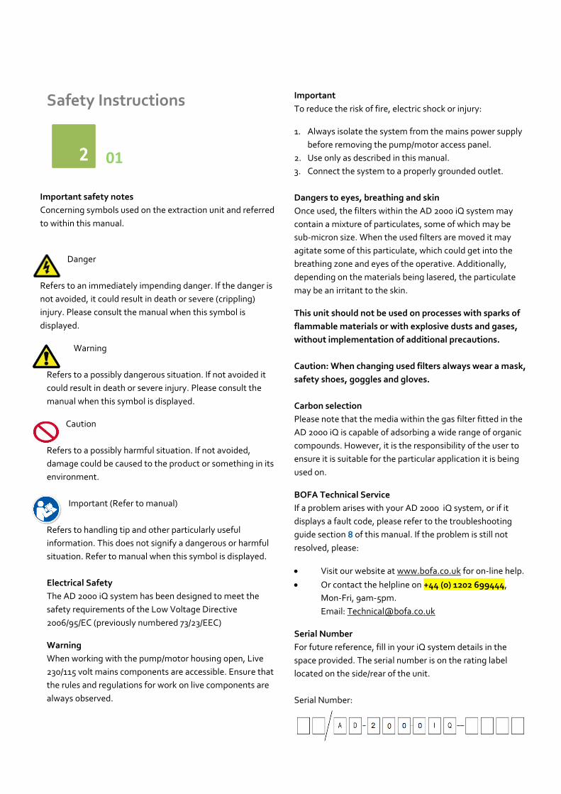
Enclosures
The extraction hose and nozzle can be attached to the
enclosure surrounding the marking zone provided that the
extraction point is within 50-75mm of the marking point.
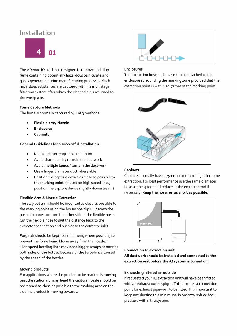
Cabinets
Cabinets normally have a 75mm 0r 100mm spigot for fume
extraction. For best performance use the same diameter
hose as the spigot and reduce at the extractor end if
necessary. Keep the hose run as short as possible.
Connection to extraction unit
All ductwork should be installed and connected to the
extraction unit before the iQ system is turned on.
Exhausting filtered air outside
If requested your iQ extraction unit will have been fitted
with an exhaust outlet spigot. This provides a connection
point for exhaust pipework to be fitted. It is important to
keep any ducting to a minimum, in order to reduce back
pressure within the system.
4 01
Installation
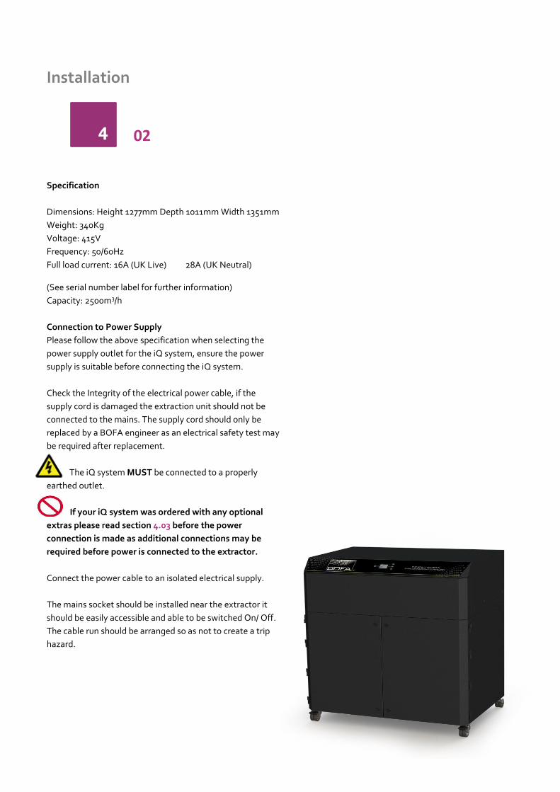
Specification
Dimensions: Height 1277mm Depth 1011mm Width 1351mm
Weight: 340Kg
Voltage: 415V
Frequency: 50/60Hz
Full load current: 16A (UK Live) 28A (UK Neutral)
(See serial number label for further information)
Capacity: 2500m3/h
Connection to Power Supply
Please follow the above specification when selecting the
power supply outlet for the iQ system, ensure the power
supply is suitable before connecting the iQ system.
Check the Integrity of the electrical power cable, if the
supply cord is damaged the extraction unit should not be
connected to the mains. The supply cord should only be
replaced by a BOFA engineer as an electrical safety test may
be required after replacement.
The iQ system MUST be connected to a properly
earthed outlet.
If your iQ system was ordered with any optional
extras please read section 4.03 before the power
connection is made as additional connections may be
required before power is connected to the extractor.
Connect the power cable to an isolated electrical supply.
The mains socket should be installed near the extractor it
should be easily accessible and able to be switched On/ Off.
The cable run should be arranged so as not to create a trip
hazard.
4 02

Installation
Optional added features
The AD 2000 iQ can be configured to suit customer
specification. These optional extras would be discussed,
arranged and installed prior to delivery.
(If unsure what features your iQ system is equipped with
please contact the seller with the unit serial number,
(Refer to section 2 for location) who will be able to advise
what specification has been supplied.
Remote Stop/Start feature
Enables the extraction unit to be remotely turned On / Off
via an external signal.
This feature can be configured in 3 ways
DC Voltage input – Range 12-24VDC
Volt free input – Open / Closed contacts
Override – Stop / Start feature switched off
Note: Care must be taken to ensure that the system is
correctly wired in order for the extraction unit to function
correctly.
DC Voltage input
This configuration requires the Black & Red cores of the
signal cable (Refer to section 1 for location) to be connected
to a known and tested DC power supply, in order to start the
extractor.
The operating voltage for this signal is between 12 &
24VDC. Only voltages within this range should be
connected. Voltages connected outside of this range may
cause irreversible damage to the internal control PCB.
Red cable = V+
Black cable = V-
When the extractor is provided with the correct DC voltage
the motor will start and maintain the set flow rate (Refer to
section 5 for how to set the flow) when the DC voltage is
removed the motor will slow down and come to a stop.
The extractor will need to be turned on and be out of
standby mode (See section 5 for turning the extractor on) in
order for this feature to operate.
Volt free input
This configuration requires the Black & Red cores of the
signal cable (see section 1 for location) to be connected
together, in order to start the extractor.
When the 2 cables are connected together the motor will
start and maintain the set flow rate (see section 5 for how to
set the flow)
when the 2 cables are disconnected the motor will slow
down and come to a stop.
The extractor will need to be turned on and be out of
standby mode (See section 5 for turning the extractor on) in
order for this feature to operate.
Override
Enables the extractor to operate fully with or without either
DC voltage input or the Volt free input.
The override feature can be toggled On / Off by a switch
mounted on the internal motor access panel (see below for
switch location)
Switch in “On” position
In this position the extractor will require a start signal (either
Voltage input or Volt free, depending on the requested
specification) to enable the motor within the extraction unit.
Switch in “Off” position
In this position the extractor motor will run without the
requirement for an external start signal. This feature is
useful for engineers carrying out works/ tests on the
extractor without the need for the laser / auxiliary signal
being present.
4 03

Installation
Filter Blocked / System Fail Signal
With this option the iQ system will output a signal to alert
the user when the extractor has failed or when the filters are
blocked.
This feature will not directly stop the extractor from running
correctly, but if fitted this feature should be terminated
correctly before power is applied to the iQ system.
Connection specification
This signal is available via the Green and White cores of the
signal cable. The iQ system will provide a volt free Open /
Closed signal that can be connected to an external interface,
beacon or warning device following the specification below.
Maximum input voltage: 24V AC
Maximum current load: 3A @ AC
OR
Maximum input voltage: 24V DC
Maximum input load: 3A @ DC
Filter Signal Configurations
There are 3 ways this signal can be configured, as detailed
below.
Combined signal (standard specification)
Separated signal
Reversed separated signal
Combined signal
With this configuration the Filter blocked & System fail
signals will be linked together to give a combined single
output.
When the filters become blocked or the iQ system develops
a fault (Refer to section 8 for Troubleshooting & Error
codes) the connection between the Green & White cables
will become “Open”
When the extraction system is running normally the
connection between the Green & White cables will become
“Closed”
Separated Signal
With this configuration the Filter blocked & System fail
signals will be separated to give 2 individual signals.
When the filters become blocked the connection between
the Green & White cables will become “Open”
If the iQ system develops a fault (Refer to section 8 for
Troubleshooting & Error codes) the connection between the
Blue & Yellow cables will become “Open”
When the extraction system is running normally the
connection between the (Green / White) & (Blue / Yellow)
cables will become “Closed”
Reversed Separated Signal
With this configuration the cable function will remain the
same as the Separated signal option, but the signal given
will be reversed.
For blocked filters the connection between the cable cores
will be “Closed”
For iQ system faults the connection between the cable cores
will be “Closed”
For system OK the connection between the cable cores will
be “Open”
4 04

Operation
Turning extraction unit On
There are 2 stages to powering up your iQ extraction unit.
Firstly the main isolation switch must be switched to the
“On” position (Refer to section 1 for switch location).This
will place the extraction unit in Standby mode, indicated by
the front panel power button glowing Red.
To start the extraction unit press the front panel power
button (refer to section 1 for switch location) the button will
change from Red to Green indicating the extraction unit is
now fully On.
It is recommended that the rear isolation switch is left in the
On position and the front standby switch is used to toggle
the extractor On / Off.
Changing the display units
The Airflow and temperature readings can be displayed in 2
ways.
1. Temperature displayed as oC
Airflow displayed as m3/h
OR
2. Temperature displayed as oF
Airflow displayed as CFM
The display value can be changed by pressing the “Enter”
button once.
5 01

Operation
Setting the desired airflow
The iQ system features automatic flow control. This enables
the user to set the required airflow rate, then over time as
the filters begin to block the motor will automatically begin
to increase in speed to compensate for any loss in
performance caused by the added restriction of the partially
blocked filters.
The extractor and all pipe work must be fully
installed and connected before the airflow is set.
To set the airflow
(The airflow can be set between 500-2500m3/h)
1. Press and hold the “Enter” (middle) button (Refer
to section 1 for button location) for 3 seconds, or
until all 3 button lights flash green.
2. Release the Enter button, the iQ system is now in
set mode. Press either the Up or Down button to
adjust the airflow accordingly.
Real time airflow is displayed on the LCD screen,
Refer to section 1 for Display information)
3. Once you have your desired airflow, leave the
controls, after around 10seconds the flashing
buttons will illuminate constantly to confirm the
airflow is stored.
The set airflow will now be maintained throughout the life
of the filters. When the extraction unit can no longer
maintain the set airflow an alarm will be given and the
display will indicate which filter should be changed.
1)
2)
3)
5 02

Operation
Airflow Auto Adjust (first installation only)
When first setting the airflow on your new extraction unit
the iQ will detect if the desired airflow is achievable with the
installation that has been connected to the extraction unit.
If the installation is causing too much restriction for the
desired airflow to be reached, the Auto Adjust feature will
be activated. The procedure events are listed below.
1) The 3 buttons will begin flashing Red along with the
airflow setting on the LCD screen.
2) The airflow setting on the screen will drop to display the
highest airflow that can be achieve.
3) The airflow will stabilise and the buttons will turn green to
show the airflow has set.
5 03

Maintenance
Maintenance UK
It is a legal requirement, under regulation 9 of the COSHH
regulations that all local exhaust ventilation systems are
thoroughly examined and tested at least once every 14
months (typically carried out annually). The approved code
of practice recommends that a visual check should be
carried out at least once a week.
COSHH requires the annual inspection and testing to be
carried out by a competent person and specifies that
documentation results are recorded in a log.
Contact the seller for more information about inspection
and certification.
Maintenance General
User maintenance is limited to cleaning the unit and filter
replacement, only the manufacturers trained maintenance
technicians are authorised to carry out component testing
and replacement. Unauthorised work or the use of
unauthorised replacement filters may result in a potentially
dangerous situation and/or damage to the extractor unit
and will invalidate the manufacturer’s warranty.
Cleaning the unit
The stainless steel units should be cleaned with a
proprietary stainless steel cleaner, in accordance with the
manufacturer’s user instructions
The powder coat finished units can be cleaned with a damp
cloth and non-aggressive detergent, do not use an abrasive
cleaning product as this will damage the finish.
The cooling inlets and outlets should be cleaned once a year
to prevent build-up of dust and overheating of the unit.
Replacing Filters
The iQ system constantly monitors the condition of the
individual filters. As the filters block the LCD display will
show the relevant filter symbol filling up. (see section 1 for
LCD details) Each filter symbol fills up in 5% increments,
when the filter icon is filled that particular filter will need
replacing.
Pre Filter blocking Combined Filter Blocking
A log of the changes should be maintained by the user.
The filters require attention when the display shows the
filter blocked icon/ filter output signal (if fitted) or when the
extractor no longer removes fume efficiently.
All filters are tested to EN1822. A certificate of conformity
for each filter is available on request.
It is recommended that a spare set of filters are kept on site
to avoid prolonged unit unavailability. Part numbers for
replacement filters can be found on the filters fitted in your
system. Alternatively, refer to the spare parts table in this
manual.
To prevent overheating, units should not be run with a
blocked filter condition, or with dust obstruction of Inlets /
Outlets.
75% filter blocked indication
When the filters become 75% blocked the buttons on the
front of the extraction unit will turn from Green to Amber
and if fitted the iQ system will output a signal to indicate
this. At this time it is recommended spare filters are
available as a change may be needed shortly.
6 01
TIM
E

Maintenance
Pre Filter Replacement
The Pre filters need to be replaced when the display flashes
between the 2 images shown below, at this point the
buttons will glow Red and if fitted the filter blocked signal
will be given. Both pre filters should be replaced.
To remove and replace the Pre filters follow the procedure
detailed below. (Both Pre filters must be changed
together)
1. Isolate the electrical supply to the extractor
2. Undo the catches on the front of the unit and open
one of the front doors.
3. The Pre filter is the lower of the 2 filters (refer to
section 1 for filter location) using the handle on the
front of the filter, pull it out of the unit.
4. Once removed it is recommend that the used filters
are bagged and sealed.
5. Slide the new filter into position making sure it is
pushed all the way in and is located correctly on the
spigot in the back of the unit.
6. Close the door and fasten the 2 latches.
7. Repeat for the other pre filter in the compartment
next to this one.
Combined Filter Replacement
The Combined filters need to be replaced when the display
flashes between the 2 images shown below, at this point the
buttons will glow Red and if fitted the filter blocked signal
will be given. Both combined filters should be replaced.
To remove and replace the Combined filters follow the
procedure detailed below. (Both Combined filters must be
changed together)
1. Isolate the electrical supply to the extractor
2. Undo the catches on the front of the unit and open
the door.
3. The Combined filter is the higher of the 2 filters
(refer to section 1 for filter location) rotate the lever
below the filter through 180o to lower the
combined filter.
4. Using the handle on the front of the filter, pull it out
of the unit being careful to support it as it comes
free as it is heavy.
5. Once removed it is recommend that the used filters
are bagged and sealed.
6. Slide the new filter into position making sure it is
pushed in all the way.
7. Rotate the lever back through 1800 to raise the
filter into position.
8. Close the door and fasten the 2 latches
9. Reconnect the power supply
10. Repeat for the other combined filter in the
compartment next to this one.
Both filters MUST be fitted when the extractor is in use, if
the combined filter is not installed correctly the iQ
system will not allow the motor to start.
6 02

. iQ System Display
iQ Display Features
The iQ display has the ability to display all the faults
associated with your extraction unit. The image below
shows an example of some of the fault icons that may
appear in the alarm window of the LCD display.
Visual Alarms on the iQ system
The iQ system can visually display a wide range of alarms on
its LCD panel. The visual displays, meanings and solutions
are detailed below. All alarms will trigger the system alarm
interface output signal and the inbuilt audible buzzer, if
fitted/ activated.
Over Temperature Alarm
If the iQ system detects an internal temperature greater
than 60oC then it will automatically shut down the extractor
to prevent damage to components within the extractor.
Once the internal temperature has dropped by 50C the
extraction unit will be able to restart.
To restart the extractor after an over temperature alarm the
unit needs to be placed in Standby mode then powered on
again.
Hose blocked alarm
The iQ system features a 2 stage Hose blocked alarm.
Partial hose blockage
Full hose blockage
Partial hose blocked alarm
This alarm will become active when the iQ system detects a
part blockage in the installation. The iQ system interprets a
partial blockage as a vacuum spike within the ductwork but
is only a partial blockage as the extractor is still able to
maintain its set airflow.
During this time it is normal to hear the motor increase in
speed. The blockage will need to remain in the ductwork for
over 5 seconds before the alarm is given.
Full hose blockage
This alarm will become active when the iQ system detects a
full blockage in the installation. The iQ system interprets a
full blockage as a vacuum spike within the ductwork and is
considered a full blocked as the extractor cannot maintain
the set airflow with the blockage present.
During this time it is normal to hear the motor increase in
speed. The blockage will need to remain in the ductwork for
over 5 seconds before the alarm is given.
To remove the blockage, isolate the extraction unit from the
mains, remove the flexible hose, locate and remove the
blockage then reattach the hose as previously installed.
7 01

iQ System Display
Heat Detection Shut off
The AD2000 iQ system has two internally mounted thermal
trips, one in each filter compartment. These detect the
temperature in the filter compartments. If the temperature
rises above 55oC then the extraction unit will automatically
shut down the motor and display the symbol below.
If this symbol is displayed the unit should be totally isolated
from the mains supply and the unit should be fully inspected
for evidence of the temperature rise. (Including inside the
Pre filters)
Once the unit is safe to turn back on and the internal
temperature has dropped below 50oC the thermal trips can
be reset. To do this follow the procedure below.
1. Isolate the supply from the extractor
2. Open the front door & remove the Combined Filter
3. Locate the circular cut out in the shelf, at the front of the
unit.
4. Inside the cut out there is a small red button that can
now be pressed back in.
5. Re-fit the Combined Filter, close the front door and re
connect the mains supply.
Gas Filter monitoring (VOC Sensing)
If the VOC (Volatile Organic Compound) sensing option has
been fitted to your iQ system then this will be constantly
monitoring the exhaust gas of the extraction unit.
If the VOC level in the exhaust exceeds the PPM (Parts per
million) level pre-set at BOFA then the Gas alarm will be
triggered and display the Gas icon as shown below.
Removing the Gas alarm warning
The VOC option is a perfect way to monitor how the carbon
section of the combined filter is performing. Once the
carbon within the filter is saturated the VOC sensor will
alarm. At this point the extractor should be isolated from
the mains and a new combined filter fitted. Once a new
filter is installed the alarm will clear.
Run Safe Feature
To ensure personnel protection and avoid damage to the
unit the iQ system will automatically shut down 5 seconds
after no combined filter is detected. If no combined filter is
fitted the motor will stop and the display will appear as
below.
To resolve this, isolate the extractor fit the combined filter
(see section 6.02) and turn the extractor on.
02
7

iQ System Display
USB Connectivity
The iQ system is equipped with a USB drive, that operates
as a 2 way device, as detailed below.
Duplicating iQ settings
Download iQ Data
Duplicating iQ settings (USB Upload)
This USB upload feature has been designed for customers
that have multiple extractors and specific set of parameters
that they wish to duplicate across their iQ extraction units.
The Procedure for duplicating extractor settings is detailed
below.
1. Obtain the memory stick file from the seller (if
specification has been pre-arranged with the seller)
Or download original settings from your master iQ unit)
(Max capacity USB Stick 4GB)
2. Download this file to a blank memory stick
3. Place the iQ system in standby mode (Front power
button glowing Red)
4. Insert the memory stick into the USB slot
5. The LCD display will show “upload” press the button
corresponding to this
6. The display will show a progress complete bar and when
finished a completion “Tick”
7. The USB stick can now be removed from the unit and
the extractor turned back On
If the USB upload procedure fails the screen
will display the symbol shown adjacent.
7 03

iQ System Display
Download iQ Data (USB Download)
With this feature the customer is able to download all stored
data within the iQ system, this information can then be used
to keep records of how your iQ system is performing, this is
also very beneficial for the technical team when diagnosing
issues with the extraction system. The following list shows
the information available within the event log.
Downloading iQ Data
To download the information from the iQ system please
follow the procedure below.
1. Obtain a memory stick (Max capacity USB Stick
4GB)
2. Place the iQ system in standby mode (Front power
button glowing Red)
3. Insert the memory stick into the USB slot
4. The LCD display will show “download” press the
button corresponding to this
5. The display will show a progress complete bar and
when finished a completion “Tick”
6. The USB stick can now be removed from the unit
and the extractor turned back On
If the USB upload procedure fails the screen
will display the symbol shown adjacent.
7 04

iQ System Display
The iQ system will take a snapshot of the system
performance every 15 minutes or if a system adjustment is
made or an alarm is triggered.
Some of the information captured is listed below..
Date
Time
Airflow
Airflow Set point
Pre filter % blocked
Combined filter % blocked
Inlet % (installation restriction)
Motor output
Internal Temperature
Hours run
Alarms
Faults
Date & Time
The date and time will be set as part of the testing stage
with the manufacturer and set to GMT.
Airflow
This column shows the real time airflow through the
extractor.
Airflow set point
Shows the target airflow that has been set by the user, this
will record every time an adjustment is made.
Pre filter % blocked
The display on the extractor will show the pre filter blocking
in 5% increments, but with this downloadable file the pre
filter blockage is shown as an exact percentage of its full
capacity.
Combined filter % blockage
The display on the extractor will show the combined filter
blocking in 5% increments, but with this downloadable file
the combined filter blockage is shown as an exact
percentage of its full capacity.
Inlet % (installation restriction)
Shows the percentage of the iQ system capacity that is
taken up by the installation (pipe work) this value would also
rise if the inlet or pipe work becomes blocked.
Motor output
Shows the percentage the motor is being run at to achieve
the airflow set by the user. This value will increase as the
filters begin to block.
Internal temperature
Shows the internal temperature of the extraction unit, the
sensor is mounted to the main PCB when this sensor
reaches 60oC it will shut down the extractor and a log will be
recorded.
Hours Run
This is a simple hours run counter that will begin from the
first time the extraction is switched on by the user. The
hours run counter will only be activated when the motor is
running.
Alarms
When the iQ system has an issue that requires the user to
act upon this is classed as an alarm, when this occurs a code
will appear in this column, the main alarm codes are listed
below.
Code Meaning
1 Door Open
4 VOC alarm
16 Over temperature
32 Inlet partially blocked
64 Inlet fully blocked
128 No combined filter fitted
512 Motor failure
2048 System 100% blocked
4096 Combined filter blocked
8192 Pre filter blocked
16777216 System 75% blocked
Faults
This column will display a code if a fault with the iQ system
is detected, for analysis of any faults in this column please
contact the BOFA helpline.
7 05

Troubleshooting
Fault Indication
The iQ system intelligently monitors the whole extraction
unit. In the unlikely event of a problem with the extraction
unit please read this section of the manual before
contacting the helpline.
This section contains details on all faults the iQ system is
able to display, these faults are detailed below.
Independent Motor Failure Detection
If the extraction unit develops a fault relating to one of the
motors then the motor icon on the display will stop rotating
and flash the airflow will read O m3/h. The alarm window will
display the motor icon and indicate which motor has caused
the failure. (example below shows a motor 1 failure).
If the above symbol is displayed power should be isolated
from the extractor and arrangements should be made to
replace the motor.
Internal Power Supply
The extractor is fitted with an internal transformer that
outputs 12V DC providing the iQ system with power.
If the buttons on the front panel are not illuminated or
operational this would indicate a problem with the internal
power supply (provided the main isolation switch is in the
ON position and voltage is proven at this point)
If the power supply has failed, arrangements should be
made to replace the transformer.
Error Codes on the iQ display
The iQ system is able to self-diagnose problems relating
directly to the monitoring system. Faults are displayed as a
number in the error window within the display.
In the event of an error code being displayed please contact
your local representative or BOFA who will be able to
diagnose the fault and advise on the most efficient solution.
USB diagnosis
For a “Real time” event log of any faults with your iQ system
please see section 7.04 & 7.05 to download a full analysis of
the extraction system.
01
8

Replacement Parts
Consumable Spares
The iQ extraction system contains a pre filter and a
combined filter. These should be replaced when instructed
to do so by the iQ system (see section 6 for replacing the
filters)
To maintain performance it is important that the filters are
replaced with identical BOFA filters. To re-order please refer
to the Filter number printed on the filter installed in your
extraction unit.
Maintenance Protocol
The iQ data logging function enables the retrieval of filter
change intervals. Users may also wish to record changes on
the table below.
Unit Serial Number:
Left Pre filter Left Combined filter
Date Engineer Date Engineer
Right Pre filter Right Combined filter
Date Engineer Date Engineer
Filter disposal
The Pre and Combined filters are manufactured from non-
toxic materials. Filters are not re-usable, cleaning used
filters is not recommended. The method of disposal of the
used filters depends on the material deposited on them.
For your guidance
Deposit EWC Listing*
Comment
Non Hazardous
15 02 03 Can be disposed of as non-hazardous waste.
Hazardous 15 02 02M The type of hazard needs to be identified and the associated risks defined. The thresholds for these risks can then be compared with the amount of material in the filters to see if they fall into the hazardous category, if so, the filters will need to be disposed of in line with the local/national regulations.
*European Waste Catalogue
01
9

System Specifications
Unit: AD 2000 IQ
Capacity: 2500m3/h (1470.5cfm)
Weight: 340Kg (749.5lbs)
Motor: Centrifugal Fan
Electrical supply: 415v 3Ph
Hertz: 50/60Hz
Full Load Current : 16A per phase (UK Live)
28A (UK Neutral)
Noise Level: Below 77dB (A)
(at typical operating speed)
Size:
Metric (mm)
Imperial (inches)
Height 1277 50.3
Depth 1011 39.8
Width 1351 53.2
Filters:
Filter Type
Quantity Surface area Efficiency
Pre filter 2 60m2 95% @ 0.9micron
Combined filter
2 15m2 99.997% @ 0.3micron
Combined Filter (Gas section)
Filter Type
Quantity Carbon type Amount
Combined filter ( Gas )
2 Activated carbon
68kgs
Environmental operating range:
Temperature: +5oC to + 40oC
Humidity: Max 80% RH up to 31oC
Max 50% RH at 40oC
10 01
Contact Information
BOFA Headquarters
21-22 Balena Close
Creekmoor industrial Estate
Poole
Dorset
BH17 7DX
UK
Phone: +44 (0) 1202 699444
BOFA Americas
303 S.Madison Street
Staunton
Illnois
62088
USA
Phone: 001 (618) 205-5007