Embed Size (px)
Citation preview
UNCLASSI FI ED
AD 266 120
1WMED SERVICES TECHNICAL INFORMATION AGENCYARUNGTON HALL STATIONARLINGTON 12, VIRGINIA
UNCLASSIFIED
NOTICE: When government or other drawings, speci-fications or other data are used for any purposeother than in connection with a definitely relatedgovernment procurement operation, the U. S.Government thereby incurs no responsibility, nor anyobligation whatsoever; and the fact that the Govern-ment may have formulated, furnished, or in any waysupplied the said drawings) specificationso or otherdata is not to be regarded by implication or other-wise as in any manner licensing the holder or anyother person or corporation, or conveying any rightsor permission to manufacture, use or sell anypatented invention that may in any way be relatedtheretco.
AF/SSD-TR-61-8 R-3135
NITROGEN TETROXIDE HANDLING MANUAL
ROCKETMYNEA DIVISION OF NORTH AMERICAN AVIATION, INC.
6633 CANOGA AVENUE, CANOGA PARK, CALIFORNIA
CONTRACT AF33 (616)-6939
PROJECT No. 3148
TASK No. 30196
SEPTEMBER 1961
ROCKET TEST ANNEX
SPACE SYSTEMS DIVISION
AIR FORCE SYSTEMS COMMAND
UNITED STATES AIR FORCE
EDWARDS AIR FORCE BASE, CALIFORNIA
AF/SSD-TR-61-8 R--13135
NITROGEN TETROXIDE HANDLING MANUAL
RocketdyneA Division of North American Aviation, Inc.6633 Canoga Avenue, Canoga Park, California
Contract AF33(616)-6939Project No. 3148
Task No. 30196
September 1961
ROCKET TEST ANNEXSPACE SYSTEMS DIVISION
AIR FORCE SYSTEMS COMMANDUIJTED STATES AiR FORCE
FD14AR/DS Ait FORCE WASE, CALIFO!iNIA
FOREWORD
This manual is one of the four propellant handling manuals prepared under
Contract AF33(616)-6939, SupplPment 1, PN 3148, TN 30196. The admini-
strative and technical direction of this effort was provided by Messrs.
F. S. Forbes, T. Marshall, and J. H. Smith of the AFFTC, Edwards Air Force
Bas'e, Califlornia. The manuals were prepared by the Analysis and Equipment
Group of the Rocketdyne Engineering Department.
The propellant handling manuals were titled and identified as follows:
AF/SSD-TR-61-7 Hydrazine Handling Manual
AF/SSD-TR-61-8 Nitrogen Tetroxide Handling Manual
AF/SSD-TR-61-9 Chlorine Trifluoride Handling Manual
AF/SSD-TR-61-10 Pentaborane Handling Manual
A group of four design-criteria manuals were also prepared under Con-
tract AF33(616)-6939, Supplement 1, PN 3148, TN 30196. These manuals
were titled and identified as follows:
AF/SSD-TR-61-6 Mechanical System Design-Criteria Manualfor Hydrazine
AF/SSD-TR-61-5 Mechanical System Design-Cri teria Manualfor Nitrogen Tetroxide
AF/SSD-TR-61-4 Mechanical System Design-Criteria Manualfor Chlorine Trifluoride
AF/SSD-TR-61-3 Mechanical System Design-Criteria Manualfor Pentaborane
iii
CONTENTS
Foreword. ... . .. .. . . .. .
Abstract. .. ... .... . . .. . iv
Introduction ............... . .. .. . . ........ ....... 1
1.0 General Description ..................... . .. .... . 3
2.0 Properties ......................... . .. . ..... . 4
2.1 General Properties ........... . . . ....... 4
2.1.1 Appearance ...................... . ... 4
2.1.2 Odor ................. . . ....... .. 4
2.1.3 Chemical Composition .... .. 4
2.1.4 Chemical Activity ........ . . .. . ........ 5
2.2 Physicochemical Properties ......... . .. . ........ 6
3.0 Materials ............ . . . .. .. . ........ ....... 9
3.1 Materials Compatibility ........... . .. . . ....... 9
3.1.1 Compatible Materials ........ . . .. . ...... 9
3.1.2 Materials for Limited Service I..... 10
3.1.3 Incompatible Materials ....... . ........ 11
3.2 Preparation of Materials ........ . . ...... .. 11
3.2.1 Degreasing ............. . . ......... 12
3.2.2 Descaling .............. . ........... 13
3.2.3 Passivation .................. . . ..... 14
3.2.4 Handling ............ . ....... ...... 15
4.0 Hazards .................... . . .......... .. 16
4.1 Toxicity ..................... . . ..... .. 16
4.2 Physiological Effects ................ . . . . 17
4.3 Fire and Explnsive Hazards.. ....... . . . 18
5.0 Hazard Reduction ................ . . ..... .. .. 19
5.1 Spill Prevention . . . . ". . . . ............ 19
5.1.1 System Integrity .. 19
5.1.2 Trained Personnel ...................... 20
5.2 Fire Prevention ...................... .. . 21
V
6.0 Hazard Control . . ............................ 22
6.1 Spill Control. ..... . ............... 22
6.2 Fire Control. ..... ................. 24
7.0 Safety Equipment ................ ...... .... 25
7.1 Facility Safety Equipment ............... .... 25
7.2 Personal Safety Equipment. . ...... . . .. 26
8.0 Decontamination ................ ....... 27
8.1 Area Decontamination ... ........ ..... .. 27
8.2 Equipment Decontamination ..... 27
9.0 Transportation . . ............................ 29
10.0 Storage .................................... 36
11.0 Handling ................. ..... ............. 38
11.1 Handling of Shipping Containers ......... ...... 38
11.2 Transfer of Nitrogen Tetroxide. .... . . . .. 38
11.2.1 Transfer From Single-Opening Containers 40
11.2.2 Transfer From Double-Opening Containers 45
11.2.2.1 Pressurization Unloading 45
11.2.2.2 Transfer Pump Unloading .... 50
11.3 Venting ................... . .... 56
1I.'j Disposal.............. ..... 56
v'i

ILLUSTRATIONS
1. Specific Gravity of Nitrogen Tetroxide . . . . . . . . . 7
2. Vapor Pressure of Nitrogen Tetroxide . . . . . . . . . 8
3. Details and Dimensions of 13-lb-Capacity Nitrogen
Tetroxide Cylinder . . . . . . . . . . . . . . 31
4. Details and Dimensions of 125-lb-Capacity Nitrogen
Tetroxide Cylinder . . . . . . . . . . . . . . . 32
5. Details and Dimensions of 10-lb-Capacity Nitrogen
Tetroxide Cylinder . . . . . . . . . . . . 33
6. Details and Dimensions of 156-lb-Capacity Nitrogen
Tetroxide Cylinder a . . . . . . . . . . . . 34
7. Details and Dimensions of 2,000-lb-Capacity Nitrogen
Tetroxide Cylinder . . . . . . a . . . . . . . . 35
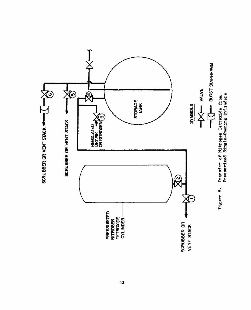
8. Transfer of Nitrogen Tetroxide from Pressurized
Single-Opening Cylinders . . . . . . a a a a . * 42
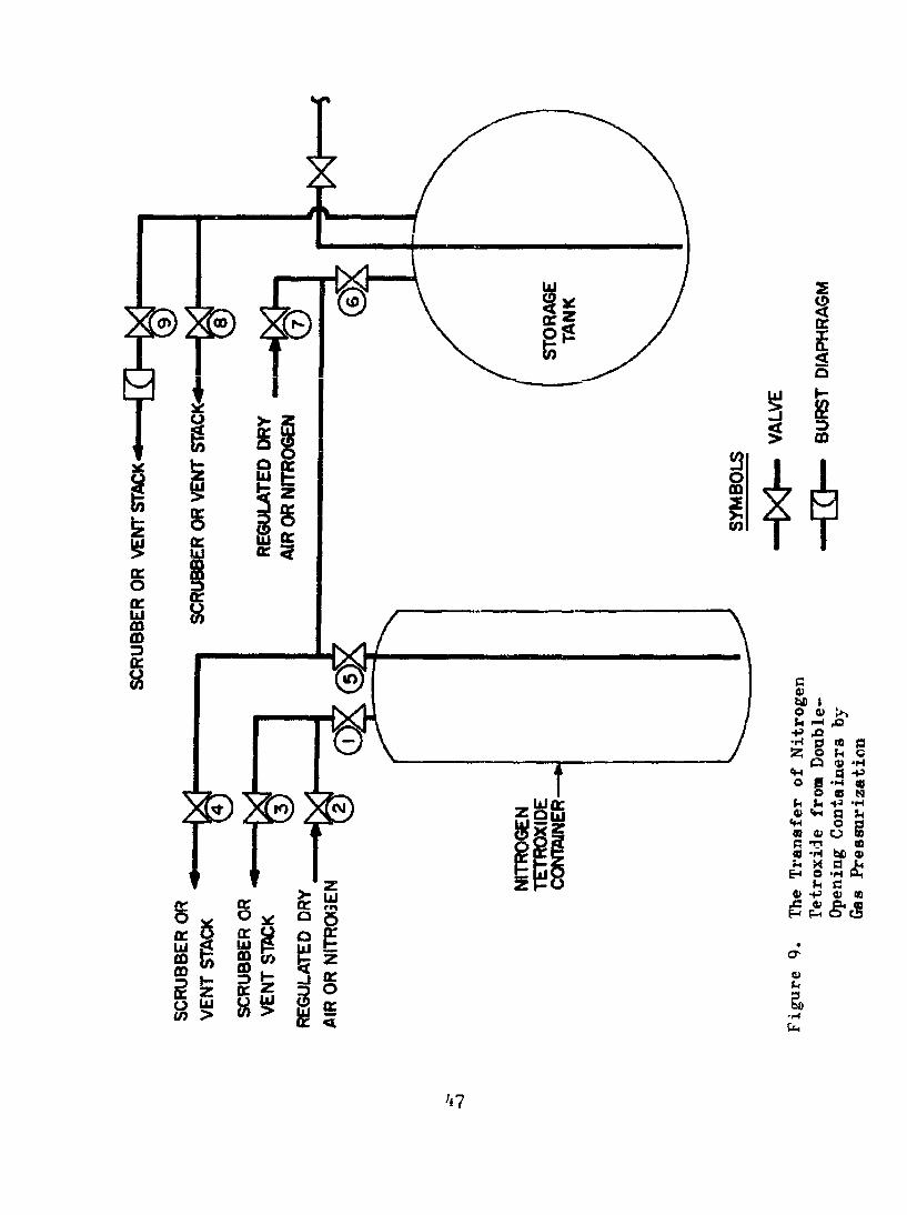
9. The Transfer of Nitrogen Tetroxide from Double-
Opening Containers by Gas Pressurizetion .. .a a .. . 47
10. The Transfer of Nitrogen Tetroxide from Double-
Opening Containers Using a Pump .a a. 52
TABLES
i. Applicable Quantity-Distance Values for Nitrogen
Tetroxide . .. . . . . . . . . . .a .a . 37
vii
INTRODUCTION
This manual presents directly usable information for the safe handling of
nitrogen tetroxide. The material presented is that evolved from both
applicable experience and a thorough evaluation of the available literature,
especially that originating from the propellant manufacturer.
The need of reliable information for the safe handling of high-energy pro-
pellants is self-evident. Although pertinent literature abounds, the ap-
plication of the published handling techniques to actual situations cannot
be successfully realized in most cases. This frustrating situation can be
attributed to the fact that most propellant handling information is obtained
as a byproduct of hardware development programs. This manual represents one
of the first concerted research efforts to formulate saxe propellant hand-
ling techniques.
The material covered in this manual is that which is considered essential
for the safe handling of the propellant. This material is presented in a
very simple and direct manner to make it usable to all personnel involved
in propellant handling operations. In addition, the techniques included
are expected to provide additional background to the designer of storage
and handling systems for nitrogen tetroxide.
The safety practices in the manual are based on the principle that the
prevention of hazardous situations is the most important consideration
for the safe handling of high-energy propellants. However, it is acknowl-
edged that a completely hazard-frpe facility cannot be ultimately realized;
therefore, serious cunsideration is also given to the control of any haz-
ardous situation that may arise.
This manual consists of eleven sections, each section dealing with a sTpe-
cific subject such as properties of the propellant, materials of construc-
tion, handling procedures, and others. This arrangement allows the user
to obtain specific informal.ion expeditiously.
2
1.0 GENETAL DESCRIPTI ON
Nitrogen tetroxide (N2 0.), also known as dinitrogen tetroxide,
NTO, nitrogen peroxide, or liquid dioxide, has a characteristic
reddish-brown color which is caused by the presence of nitrogen
dioxide (NO2 ) in varying amounts, depending upon the temperature
and pressure. This propellant can be harmful when inhaled as a
vapor and can cause serious burns when the liquid comes in contact
with any part of the body, internally or externally. Since nitro-
gen tetroxide is a very reactive oxidizer, it can cause fires with
many combustible materials.
As a storable liquid oxidizer, nitrogen tetroxide offers for liq-
uid-fueled rockets the readiness approaching that of solid propel-
lant rockets. Its oxygen content, about 70 percent by weight,
gives nitrogen tetroxide a performance approaching that of liquid
oxygen. Under similar operating conditions, the theoretical spe-
cific impulse of the nitrogen tetroxide-hydrazine combination is
292 seconds and that of the liquid oxygen-hydrazine combination is
313 seconds.
"Nitrogen dtroxide boils at approximately 70 F. As a result, re-
frigeration is not required to keep it in the liquid state in con-
ventional moderate-pressure vessels. When stored and transferred
in clean, airtight, moisture-free systems, and handled by trained,
conscientious personnel, nitrogen tetroxide need present no seri-
ous storage or handling problem.
'3
2.0 PROPERTIES
2.1 General Properties
Because the nitrogen tetroxide propellant exists as a mixture
of nitrogen tetroxide (N2 04) and nitrogen dioxide (NO2 ) in equi-
librium, the properties presented below pertain, for the most
part, to mixtures of the tetroxide and the dioxide. However, the
properties are reproducible since the chemical equilibrium between
the two oxides is established almost instantaneously.
2.1.1 Appearance
Nitrogen tetroxide has a characteristic reddish-brown color in
both liquid and gaseous phase. In the solid state, nitrogen
tetroxide is colorless.
2.1.2 Odor
Nitrogen tetroxide has an irritating, unpleasant, acid-like odor.
2.1.3 Chemical Composition
The composition of nitrogen tetroxide established by Military
Specification MIL-P-26539, expressed in percentage by weight, is
as follows:
N20 assay 99.5 min.
H20 equivalent 0.1 max.
C1 as NOC1 0.06 max.
Nonvolatile (ash) 0.01 max.
If
2.1.4 Chemical Activity
Nitrogen tetroxide is a very reactive, toxic oxidizer. It is in-
sensitive to mechanical shock, heat, or detonation. Although it
is nonflammable with air, it can support combustion of ordinary
combustible materials.
In oxidation reactions, nitrogen tetroxide resembles ozone and
hydrogen peroxide. It is hypergolic with high-energy fuels such
as hydrazine and unsymmetrical dimethyihydrazine at atmospheric
pressures.
Several nitrogen tetroxide reactions are of considerable import-
ance to the propellant handler since they constitute the basis
for propellant neutralization, disposal, and decontamination op-
erations. Some of the typical reactions are as follows:
1. Reaction with water. Nitrogen tetroxide reacts with
water to form nitric acid as follows:
N204 + 1120"--,HNO3 + HN0 9
The nitrous acid undergoes decomposition:
3HN1209 --* HN0 + 2N0 + H2 0
2. Reaction with sodium carbonate and sodium hydroxide.
The nitrogen tetroxide reaction with sodium carbonate
and sodium hydroxide follows the following equations,
respectiveiy:
N20 4 + Na 2 CO3 -* Na NO3 + Na NO2 + C02
N2 0 4 + 2NaOHi1aý Na NO3 + Na NO. + 1t20
5
2.2 Physicochemical Proerties
Molecular Weight 92.016
Boiling Point 70.07 F
Freezing Point 11.84 F
Specific Gravity 1.447 at 68 F
Density 90.34 lb/ft' at 68 F
12.08 lb/gal at 68 F
Gas Specific Gravity 3.40 (air=l) at 70 F and 1 atm
Vapor Pressure 5.1 psia at 32 F
14.7 psia at 70 F
35.3 psia at 1.04 F
Viscosity 2.84 x 10"4 lb/ft-sec at 68 F
Heat of Formation, liquid -12,240 fLtu/lb-mol at 77 F
Heat of Fusion 68.5 Btu/lb at 11.8 F
Heat of Vaporization 178 Btu/lb at 70.07 F
Heat Capacity 0.367 Btu/lb-F at 62 F
The specific gravity and vapor pressure of liquid nitrogen
tetroxide as a function of temperature are presented in Fig. 1
and 2, respectively.
6
1.50 .J
1.49
"[48-- --
- - - _ - --
1.47
1.46
t.45 - 1
1 .4444
1 .43
COMMERCIAL GRADE1.42
"1.41
1. 40PURIFIED GRADE
1.39
1.38
1.37
1.36
1.35 -
1.3 4 - - - -
0 10 20 30 40 50 60 70 80 90 100 10 120 130TEMPERATURE, F
Fig-ure 1. Specific Gravity of Nitrogen Tetroxide
7
IO0.0 ... .... r .-
&QO500 ,
4Q0 -- _ _ - - - -
30.0 -. -
10.0 -,
9..0-ao• -
6.0 -
5.0 -
4.0/ -
3.0- -. -.
2.0
10 20 30 40 50 60 70 80 90 100 110 120 130 40 50TEMPERATURE, F
Figure 2. Vapor Pressure of Nitrogen Tetroxide
3.0 MkTERIALS
3.1 Materials Compatibility
Nitrogen tetroxide is compatible with a wide spectrum of materi-
als of construction. However, considerable care must be exercised
in selecting suitable materials due to the reactivity of the pro-
pellant and the need to prevent leaks and spills. In addition,
the compatibility of several materials of construction with nitro-
gen tetroxide depends upon the amount of water contamination pres-
ent in the propellant.
Nitrogen tetroxide reacts with water to form nitric acid which is
more corrosive to most materials of construction than nitrogen
tetroxide itself. Therefore, all. nitrogen tetroxide systems and
components must be absolutely dry.
3.1.1 Compatible Materials
The following materials and lubricants have been found to be com-
patible with nitrogen tetroxide:
Aluminum Alloy No. 1100
Aluminum Alloy No. 5052
Aluminum Alloy No. 6061
Aluminum Alloy No. 6066
Aluminum Alloy No. 356
Aluminum Alloy No. B356
Aluminum Alloy Tens 50
Stainless Steel AISI 300 Series
Stainless Steel AISI 400 Series
Stainless Steel AM-350
9
Stainless Steel AM-355
Stainless Steel 17-4 P11
Stainless Steel 17-7 PH
Iron-Base Superalloy A-286
Iron-Base Superalloy 16-25-6
Inconel-X
Chromium Plating
Teflon
Teflon filled with asbestos or glass
Teflon-fiberglass (LNP)
Viton A
Viton B
NA2-205-2 (Alochlor-1254 Monsanto)
Graphite (dry)
Molycote Z (binderless)
3.1.2 Materials for Limited SArvice
The following materials have been found to be satisfactory for
limited service in nitrogen tetroxide:
Mild Steels
Fluoro-Silicone Rubber (LS-53 Series)
Polyethylene
Keroseal
Saran
NOTE: Since these materials are attacked by nitrogen tetroxide
under some expected conditions or time duration, their use
is not recommended.
I(1
3.1.3 Incomatible hterials
The following materials and lubricants have been found to be in-
compatible with nitrogen tetroxide and must not be used:
Aluminum Alloy No. 2024 Johns-Mansville Packing No. 60
K-Monel Johns Mansville Packing No. 76
Brass Kel-F Elastomer
Bronze Mylar
Silver Buna-N
Copper Hypal on
Titanium Dow Corning Lubricant No. 55
Zinc (MIL-G-4343)
Cadmium Oxylube
Nickel ?rL-L-6086
Micarta DC 11
MIL-L-25336
3.2 Preparation of Materials
All components of a nitrogen tetroxide transfer and/or storage
system must be properly prepared prior to installation. Prepar-
ation procedures consist of rendering the components chemically
inert to the propellant.
Itews such as valves, pumps, etc., cannot be cleaned in the
assembled state since solvents may damage nonmetallic components
or residues may be trapped in inaccessible areas. Consequently,
the cleaning of these items must be done before the component
parts are assembled.
ii

The preparation of materials generally eonsists of dagreas'iio-
descaling, passivating, and drying. The cleaning solutions uti-
lized on these operations shall be applied by immersing, spraying,
wiping, circulating, or iq any other manner as long as the sur-
faces to be cleaned are completely wetted in the solutions. Any
component which can trap or retain liquids shall be drained or
emptied between applications of different cleaning solutions.
All solutions shall be made with distilled, deionized, or clean
tap water and all chemicals shall be of chemically pure grade or
better. The water shall be filtered through a 40-micron nominal-
size filter.
3.2.1 Degreasina
Components fabricated of stainless steel, aluminum, and aluminum
alloys can be degreased by cold-flushing or vapor degreasing with
trichloroethylene, or by flushing with a mild alkaline solution
containing from 5 to 7 oz of Turco #4090* (or equivvlent) per gal-
lon of water at 140 to 160 F. The application of the mild alka-
line solution shall be followed by a thorough water rinse.
Nonmetallic components, such as 0-rings, gaskets, etc., shall be
degreased by immersion or scrubbing with the mild alkaline solu-
tion described above, followed by a thorough water rinse.
Items which are not to be cleaned any further, such as nonmetal-
lic components or simple components fabricated of machined alumi-
num stock, shall be dried by flushing with dry, hydrocarbon-free,
filtered nitrogen gas, or by heating in an oven tit. 140 to 160 F.
"lurco #4090 is furnished by Turco Products, Inc., 6135 So. Cerj-
tral Avenue, Los Angeles, California.
12
3.2.2 Descaling
Newly fabricated or reworked components which have scale result-
ing from welding or heat treatment, or impurities resulting from
casting or forging, shall be descaled. Descaling solutions should
not be used after precision machining unless the finished surfaces
are protected.
The descaling of stainless steel components is accomplished as
follows :
1. Etch at room temperature for a period of no longer than 60
minutes with an aqueous solution containing from 3 to 5
weight percent technical grade hydrofluoric acid and from
15 to 20 weight percent technical grade nitric acid.
2. Rinse thoroughly with water to remove all traces of the
scaling solution.
NOTE: If the components are to be immediately passivated after
descaling, they need not be dried. Otherwise, the compon-
ents may be dried by purging with dry, hydrocarbon-free,
filtered nitrogen gas or by heating in an oven at 140 to
160 F.
The descaling procedure for components fabricated of aluminum or
aluminum alloys is as follows:
1. Clean with Turco Smut-Go* solution (1 lb/gallon of water),
or an approved equivalent cleaner, until the surfaces are
visibly clean and shiny.
4Turco Smut-Go is a chromic acid cleaner furnished by the Turco Products,Inc., 6135 So. Central Avenue, Los Angeles, California
13
2. Rinse with water to remove all traces of the acid solution.
If the components are to be immediately passivated after de-
scaling, they need not be dried. Otherwise, the components
may be dried by purging with dry, hydrocarbon-free, filtered
nitrogen gas or by heating in an oven at 140 to 160 F.
3.2.3 Paskivation
The passivation procedure for components fabricated of stainless
steel is as follows:
1. Immerse for a minimum period of 30 minutes, at room tempera-
ture, in an aqueous solution containing from 45 to 55 percent
(by weight) technical grade nitric acid.
2. Rinse with water to remove all traces of the passivating
solution.
3. Dry by purging with dry, hydrocarbon-free, filtered nitrogen
gas or by heating in an oven at 140 to 160 F.
NOTE: Acid passivation of components having highly polished or
lapped surfaces may be omitted if the finished surfaces
cannot be conveniently protected from the acid solution.
Components fabricated of aluminum or aluminum alloys can be pas-
sivated as follows:
1. Immerse for a minimum period of one hour, at room temperature,
in an aqueous solution containing aLvit 45 percent (by weight)
technical grade nitric acid.
2. Rinse thoroughly with water to remove all traces of nitric
acid.
14
3. Dry by purging with dry, hydrocarbon-free, filtered nitrogen
gas or by heating in an oven at 140 to 160 F.
3.2.4 Handling
Items that have been prepared for nitrogen tetroxide service shall
be handled, stored, or packaged in such a manner as to prevent re-
contamination. Large components such as valves, piping sections,
tanks, etc., should have all openings capped with clean compatible
materials. Small items can be sealed in clean plastic bags.
15
4.0 HAZARDS
4.1 Toxicity
Nitrogen tetroxide, like other oxides of nitrogen, is very
toxic and inhalation of even dilute concentrations should be
avoided. Exposure of the skin to liquid or vapor nitrogen
tetroxide is also to be avoided. In 1960, a maximum allowable
concentration (MAC) of 5 ppm (designated as "nitrogen dioxide")
in air for an eight-hour day continuous exposure, was adopted
by the American Conference of Governmental Industrial Hygien-
ists. From recent experience, it appears that exposures of
50 to 75 ppm can be tolerated for short periods of time.
Nitrogen tetroxide vapor, at ambient temperatures, have a char-
acteristici reddish-brown color, which in good light, becomes ap-
parent at about 50 ppm. It should be noted that the propellant
vapor cannot be seen at safe concentrations.
Nitrogen oxides are particularly treacherous in that they have a
mild odor and produce no strong immediate irritation; however,
they produce a very strong delayed action several hours later.
If an individual is exposed to strong concentrations, he should
hold is breath, if possible, until fresh air is reached. If un-
able to do this, breathing should be as shallow as possible. The
exposed individual should be placed in the care of an authorized
physician as soon as possible. In the meantime, first-aid treat-
ment can be administered as directed by the local medical author-
ity. For this purpose, it is recommended that at least one person
permanently assigned to the storage area be properly trained in
first-aid techniques. These techniques must be established only
by the responsible medical authority.
16

4.2 Physiological Effects
Precise proof is lacking that nitrogen oxides, as such, are irri-
tant nr toxic; hnwever, in the atmosphere or in living bodies they
form compounds which are irritant and intoxicant. Every milligram
of nitrous gases entering the body, yields through chemical reac-
tion, more than a milligram of nitrous and nitric acids. Before
these acids are neutralized, pulmonary irritation may occur lead-
ing to upper respiratory tract and pulmonary edema, laryngitis,
bronchitis, and pneumonitis. In humans, the occurrence of this
characteristic edema may not be detectable immediately, but it is
usually delayed for 6 or more hours. Later, the patient may com-
plain of dizziness, headache and weakness; this may be followed
by difficult breathing. Should the patient recover from this
edematous condition, he would be susceptible to bacterial invasiotn
of the lungs and consequent pneumonitis.
Any person who has or may have inhaled a considerable quantity of
nitrogen tetroxide vapor should be kept under hospitalization or
medical observation for a period of 24 hours since the person may
be developing symptoms without being aware of it.
The effect of liquid nitrogen tetroxide spillage on the skin is
similar to that caused by a 6 5-percent nitric acid solution. The
gas, which is less corrosive for the same contact time, causes a
stinging sensation similar to that of nitric acid fumes. The re-
action is local however, and generally there will not be suffici-
ent penetration of the body to produce toxic effects.
17

If a person has suffered skin or eye exposure to liquid or vapor-
ized nitrogen tetroxide, the exposure areas should be washed im-
mediately with copious quantities of water for at least 15 minutes.
The affected individual should be placed in the care of an author-
ized physician as soon as possible.
4.3 Fire and Explosive Hazards
Although nitrogen tetroxide is very reactive chemically as an oxi-
dizer, it is insensitive to mechanical shock, external heat, and
detonation. The hazard associated with nitrogen tetroxide lies
not in its flammability or explosiveness, but in its high reac-
tivity and ability to support combustion and form explosive mix-
tures with combustible substances. As a result, storage and use
areas should be kept free of all litter, rubbish, solvents, and
other combustibles.
18
5.0 HAZARD REDUCTION
Spills of nitrogen tetroxide present a hazard from both intoxi-
cation and fire as described in the HAZARDS section. For this
reason, it is necessary to prevent propellant spills whenever
possible and to control the spills and fires safely when they
occur.
5.1 Spill Prevention
The prevention of nitrogen tetroxide spills is one of the most
important considerations for the safe handling of the propellant.
Spills are the main cause of personnel intoxication and facility
damage. Effective spill reduction is accomplished by the use of
properly designed equipment and thoroughly trained personnel.
5.1.1 System Integrity
The integrity of the storage and transfer system cannot be over-
emphasized. The system shall be reliable, flexible, and easy to
operate and maintain. Some of the design criteria that shall be
incorporated on the system are as follows:
1. Only materials of construction which are definitely known to
be compatible with the oxidizer shall be employed
2. The number of mechanical joints shall be reduced to a minimum,
thus reducing the probability of propellant leakage
3. The system shall be designed to withstand the maximum operat-
ing pressure safely
4. The transfer lines shall be free of liquid traps
5. An inert-gas system must be provided to purge the transfer
lines without the necessity of dumping the residual propel-
lant or disconnecting any system joints
19
6. The system components must be reliable, compatible with the
oxidizer, and properly serviced
7. The nitrogen tetroxide vents shall be ducted together and
connected to a vapor scrubber or a high vent stack
8. Sufficient control equipment must be provided in order to
isolate portions of the system during emergencies or compon-
ents replacement
The continual observation of an operational system for possible
malfunctions can prevent serious propellant spills. The leakage
of nitrogen tetroxide vapors becomes obvious b-cause of the red-
dish-brown color of the oxidizer and the tainted surface surround-
ing the leaking area. Thus, if a small leakage is noted, correct-
ive action must be taken as soon as possible.
5.1.2 Trained Personnel
Properly trained personnel are required to handle nitrogen tetrox-
ide safely. Operating personnel shall be thoroughly familiar with
the following:
1. The properties of nitrogen tetroxide
2. Operation of the transfer and storage system
3. Toxicity and physiological effects of the propellant
4. Operation and use of the safety equipment
5. Fire and spill prevention tecimiques
6. Fire and spill control measures
7. Disposal and decontamination techniques
8. Local operating procedures and regulations
20
NOTE: No person should be allowed to handle nitrogen tetroxide
unless he is thoroughly familiar with the aforementioned
items and he is also confident that the propellant can be
handled safely with the equipment and facilities available
to him.
5.2 Fire Prevention
Nitrogen tetroxide, although not flammable nor explosive in air,
is a highly reactive oxidizer agent and should not be permitted
to come into contact with organic or combustible materials. To
prevent fires in case of propellant spillage, the storage and
handling areas shall be kept free of litter, rubbish, solvents,
and other combustibles.
21
6.0 HZATW CONTROL
In case of nitrogen tetroxide spillage or fire, all personnel
shall report to their predesignated safe areas or emergency op-
erating posts. Immediate evaluation of the hazardous situation
is necessary so that appropriate control action can be initiated
in the shortest possible time.
The time period between the inception of the hazardous situation
and initiation of control action shall be reduced to a minimum.
This can be accomplished through proper planning, training, and
organization. The following items shall be considered in the ad-
ministration of the storage and handling areas:
1. Safe areas and evacuation routes shall be pre-established
2. Only authorized personnel shall be allowed to enter these
areas
3. At least two operating personnel shall wear protective cloth-
ing and equipment during propellant handling operations
4. Periodic drills shall be performed to ensure personnel pro-
ficiency during emergency operations
6.1 Spill Control
A propellant spill can be most efficiently controlled by perform-
ing the following steps chronologically:
1. Stop the propellant handling operations
2. Isolate, by closing the necessary valves, the propellant
tanks from the transfer lines
3. Locate the source of spill
22
4. Isolate the affected components by closing the necessary
valves
5. Dispose of the spilled propellant
The performance of the first four Rntep listed above should be
automatic and can be performed in a very short time.
The disposition of the spilled propellant should not be too diffi-
cult, especially when propellant handling is performed only during
satisfactory weather conditions and the first four steps listed
above are quickly executed. The disposition method depends
greatly on the quantity of propellant spilled, prevailing weather
conditions, location of storage and/or handling area, etc. There-
fore, the discussion presented herein will be limited to general
criteria which will be applicable to most situations.
If the quantity of spilled propellant is small and the vapor is
diffused rapidly and safely, the propellant can be allowed to vap-
orize until depletion. The spilled propellant can also be disposed
of by deluging the spill area with copious quantities of water.
The water not only reacts with the tetroxide to form nitric acid,
but also increases the rate of propellant vaporization. However,
if the quantity of spilled propellant is small and a properly de-
signed water fog system is used, the amount of tetroxide vapor
leaving the spill area is reduced significantly.
The control techniques applicable to large nitrogen tetroxide
spills are dependent upon the maximum tolerable propellant vapor-
ization rates. A minimum rate is experienced when the spilled
propellant is allowed to vaporize until depletion. However. a
23

large amount of vLp;)r is still generated over a relatively long
period of time. Deluging the spill area with copious quantities
of water would deplete the propellant in a very short period of
time; however, the propellant vaporization rate is drastically
increased. A wattr fog system would have little effect in reduc--
ing the amount of tetroxide vapor leaving the spill area.
After the spill is controlled, the entire area must be thoroughly
decontaminated. Decontamination techniques are presented in an-
other section of this document.
6.2 Fire Control
The criteria presented for spill control is equally effective
for controlling fires. In this instance, however, the fire con-
stitutes an additional hazard. The heat generated by the fire
can damage mechanical and electrical components and weaken struc-
tural members, The water deluge technique is especially effect-
ive under these conditions since it not only controls the spill
but also reduces the temperature of the materials exposed to the
fire.
24

7.0 SAFETY EQUIPMT
The toxicity and chemical reactivity of nitrogen tetroxide dic-
tate that appropriate safety equipment must be provided for the
protection of the storage and handling areas and operating per-
sonnel. Although it is recognized that the type of personal
safety equipment depends upon several factors such as facility
design and personnel assigned tasks, it is suggested that only
one type of safety equipment be specified and enforced. This
criteria reduces the misunderstanding among operating personnel
as to what degree of protection is required for a specific job
assignment and prevents "short-cut" methods which are difficult
to spot-check and which can result in serious accidents.
7.1 Facility Safety Equipment
Facility safety equipment shall consist of personnel emergency
showers, eye baths, water deluge system (preferably of the fog
type), fire blankets, portable fire extinguishers, first-aid
kits, and fire hoses. This equipment shall be strategically lo-
cated and easily accessible.
All operating personnel shall be thoroughly familiar with the
location and operation of each piece of safety equipment. The
operation of the safety equipment must be verified periodically.
The installation of a nitrogen tetroxide vapor detector is recom-
mended in poorly ventilated facilities. This is necessary because
the color of nitrogen tetroxide becomes apparent at 50 ppm, whereas
the maximum allowable concentration (MAC) is only 5 ppm.
25
7.2 Personal Safety Equipment
Personnel handling nitrogen tetroxide should wear fully protect-
ive equipment. If the operations are performed remotely, it is
still recommended that at least two operating personnel be fully
dressed to facilitate proper spill and fire control.
The following permnnel protective equipment, or its equivalent,
is recommended:
1. Flameproof coveralls
2. Suit, Gra-Lite
3. Gloves, polyethylene impregnated
4. Hood, Gra-Lite
5. Boots, Gra-Lite
6. Respirator, self-contained or air-line connected
The above equipment must be maintained clean and in good operat-
ing order. A contaminated suit, for example, can become a defi-
nite safety hazard.
NOTE: The above equipment recommendation is based
only on its proven compatibility character-
ietics and commercial availability. However,
the equipment is heavy, uncomfortable, and
bulky. A need for more appropriate personal
safety equipment definitely exists.
26
8.0 DECONTAMINATION
Decontamination involves the removal of nitric acid from the
handling and storage areas following a propellant spill and the
deactivation of facility equipment exposed previously to nitro-
gen tetroxide. On both occasions, decontamination procedures are
employed to protect personnel and equipment. Personnel performing
decontamination operations shall wear the fully protective equip-
ment described in the SAFETY EQUIPMENT section.
8.1 Area Decontamination
The primary contaminant remaining from a propellant spill is the
nitric acid formed from the reaction of the nitrogen tetroxide
with water. Because this acid is extremely corrosive, it must be
removed; this can be effected by washing the area with copious
quantities of water. The drained water becomes, in turn, contami-
nated with the acid and must be disposed of as stipulated by local
regulations.
The removal of nitric acid can be effected also by washing the
contaminated area with a soda ash-water solution or other mild
alkali solution. The removal of the acid, in this case, is based
on reacting the acid with a chemical yielding soluble salts and
water as reaction products. The treated areas must be rinsed sub-
sequently with water to remove the excess of alkali solution,
which can also he corrosive. The drained solution must be dis-
posed of according to local regulations.
8.2 Equipment Decontamination
The removal of a component from a nitrogen tetroxide system must
be preceded by a thorough gas purge to remove any residual
27
propellant. If the removed component is to be reused without ser-
vice or modification, no further decuntamination operations are
required. Otherwise, the removed component is purged thoroughly
with water and dried by purging it with gaseous nitrogen.
All components removed from a nitrogen tetroxide system must be
labeled clearly, describing the extent of decontamination and op-
erational status.
28
9.0 TRANSPORTATION
Shipment of nitrogen tetroxide in quantities of up to 10,000 gal-
lons has been authorized by the Interstate Commerce Commission
(ICC). The propellant is classified by the ICC as a "Class A,
Poisonous Gas," and as such is subject to those regulations estab-
lished for this group. In transit, cylinders must be affixed with
a poison gas label (white) as specified in the regulations. Truck
and rail cars containing nitrogen tetroxide must be identified with
"Poison Gas" placards in letters at least 3 inches high on a con-
trasting background. As a poison, it is not acceptable for rail
express shipment. Interconnecting cylinders by any means while
in transit is strictly prohibited. Safety relief devices which
would allow release of vapor to the atmosphere are prohibited.
The cylinder fittings are encased in gas-tight protective caps to
prevent leakage and damage.
The following containers have been ICC approved and are currently
being used by the propellant manufacturer:
1. Cylinders (high-pressure seamless steel)
ICC-3D480 10 lb net and 156 lb net
ICC-3A2015 13 lb net
ICC-3A1800 125 lb net
2. Cylinders (forged steel, welded)
ICC-106A500-X 2000 lb net
3. Tank cars (single unit cars)
TCC-103A00-W l•000 gal
90
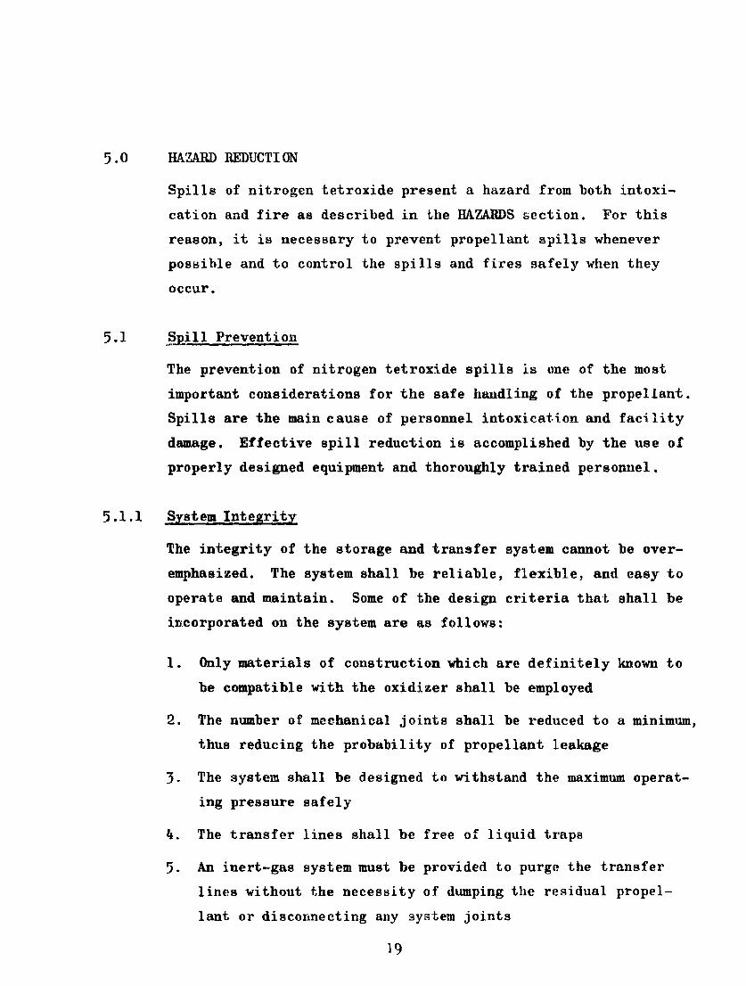
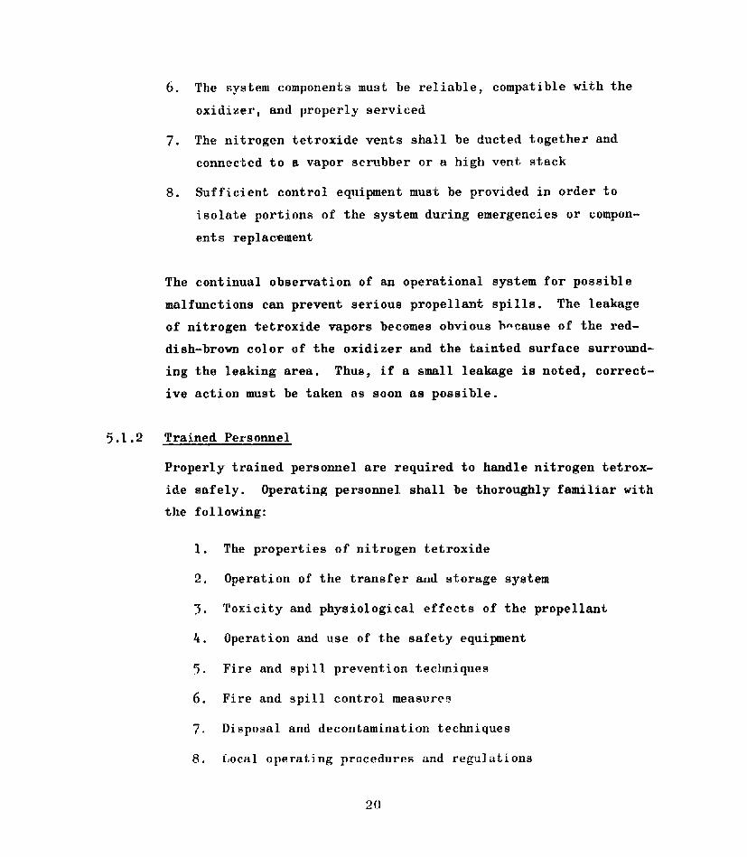
Details and dimensions of the 13-lb and 125-lb-capacity nitrogen
tetroxide cylinders are shown in Fig. 3 and 4, respectively.
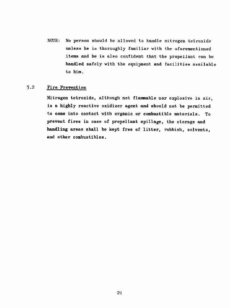
These cylinders are closed by a screwed plug. The 10-, 156-, and
2000-lb cylinders are equipped with stainless-steel valves; the
details and dimensions are shown in Fig. 5, 6, and 7, respectively.
30
GAJ SERVICE Me- 60f SOUARE
- 4Z
CYLINDER SPECIFICATION ICC-3A2015
TARE WEIGHT (APPROX.) 18 L.BS.
Figure 3. Details and Dimensiona of 13 - lbCapacityv Nitrogen Tetroxide Cylinder
31
CAP N IW1
GASKET W ..... ES Q U A R E O ., I ". g - "P j. 0 x IF$ 0D x isTHICK
PLU._G ,,,. . .M w No 60
9',
OUTSIOE DIA.
01CYLINDER I
I--A
CYLINDER SPECIFICATION ICC-3AI800
TARE WEIGHT (APPROX.) 127 LBS.
Figure 14. it ile.i a n4 nimensions -.f 125 - lbCapacity Nitrogen Tel trxide C]i Inder
32
I:
CAP_ _. -:
"I DiOx 2I OD. xT THICK
GASKET - JM SERVICE Na.6O
1i"STAINLESS STEELVALVE
---- 403SS BODY-304SS STEIM
CYNR ' DIP PIPE 19f" LONG
VIPS' 304 STAINLESS
"Y S..STEEL
* IP
SECTION A-A
VALVE DETAIL
CYLINDER SPECIFICATION ICC- 3D480
TARE WEIGHT (APPROX.) 31 LBS.
Figure 5. Details and Dimensions of 10 - lb
Capacity Nitrogen Tetroxide Cylinder
33
CAP
I~l-D 21" 0D. 'THICKGASKET J M SERVICE We 60
1 4 STAINLESS STEEL* I VALVE
403 SS BODY-304SS STEM
DIP PIPE 46V~LONG"IPS - 304 STAINLESS
STEEL
CYLINDER O" --.
*NPT 11KIATE
DIP
VALVE DETAIL I
CYLINDER SPECIFICATION ICC-3D480TARE WEIGHT (APPROX) 205 LBS.
Figure 6. Details and Dimpnmiona of 16 - lbCapacity Nitrogen Tetroxide Cylinder
34
UA-4'ka
UIBLBRIG iaisj1nOTo
z -4
4. ..- q-4.,.
Zw
r2. 4 r
00eiJ
0N
I-,
35

i0.0 STORAGE
Nitrogen tetroxide can be stored for periods of several years
without adverse effects to the container and propellant. Such
extended storage can be obtained only in clean, moisture-free,
closed systems. The ICC-approved containers in which the propel-
lant is transported can be used for temporary storage. Facility
storage and use tanks should be fabricated of stainless steel be-
cause the possibility of moisture contamination is to be expected.
Nitrogen tetroxide is classified by the I f. Air Force General
Safety Procedures for Chemical Guided Missiles Propellants, as a
"Group 11, Class A, Poisonous Substance," thus placing it in the
same category as liquid fluorine. This document, T.O. 11C-1-6,
dated 1956, is the present authority for establishing quantity-
distance relationships for the storing of most of today's liquid
rocket propellants. The quantity-distance values presently estab-
lished for nitrogen tetroxide "Poison Hazard" are presented in
Table 1.
Nitrogen tetroxide cylinders must be located and positioned so
that they are secured against rolling or being inadvertently
tipped over. This can be accomplished by placing them in cradles.
Cylinders of capacity less than 2000 lb nf nitrogen tetroxide can
be placed vertically and secured with chains. Individual cylinder
support is preferred.
When tank cars are used to store the propellant, the brakes must
be set and the wheels chocked.
36
$4
S 0 0 Q C
$40~0 0 0 0 0 40-+q r-4~$ 0 0 04 0l 0 0
.00 bb0 l ~ '' ~ L ~ ()-
ON 04
o bb1
0 Nk
rO 4bb0 bJd u 0 0 0 0 0.N0.4 % 0 i uf ý 00 0 0N ~~
E4~~~~ý 0-P-4 in 'I Cl - C
E-4 +))$4 4):3 Q,0 m
0~ Q.0.r.-4 I' 1C 0 0 tC' 0 0 0to .0) - f4 Cl Cl - C1ý
$4 0 )0
+2
0 ~~ Cb.) 4-
rd~~ > 0pt4-1 A 0 0f' 0 LA., %.i 0
0 k C 0
* L$4~~-4 --4$
0*0 0 0 0 0
0.- 01 0 0 0 0+- 0 > 00e12.-4 LA -4 0 C c
z P64 .- 4 h-4 44 0
37 0
11.0 HANDLING
Nitrogen tetroxide handling operations, as described herein, in-
cludes the unloading of shipping containers, loading of storage
tanks, venting, and disposal operations. Personnel performing
these functions must wear the fully protective equipment described
in the SAFETY EQUIPMENT section. Another activity closely associ-
ated with the above operations is the handling of the shipping
containers. The shipping containers can be handled safely with-
out the need of fully protective equipment.
11.1 Handling of Shipping Containers
The shipping containers must be handled gently and carefully.
They must not be dropped, tumbled, dragged, or allowed to bump
into other containers, walls, or projections. The containers'
protective caps must be installed at all times during handling
operations.
The containers may be transferred by means of truck, crane, fork-
lift, or any other piece of equipment capable of handling them
safely. While in transfer, the containers must be firmly secured.
Storage of the shipping contaiters should be restricted to those
areas specifically allocated for this purpose. The condition of
each container (full, empty, contaminated, etc.) should be markod
clearly.
11.2 Transfer of Nitrogen Tetroxide
Nitrogen tetroxide can be transferred using several methods. The
propellant can be discharged by its own vapor pressure, or by pres-
surizing the container with dry nitrogen or air, or by connecting
38

a transfer pump in the discharge line. Although these transfer
methods have been used in the past, the discharge of the propel-
lant appears to be most reliably performed by pressurizing the
container with dry nitrogen.
The propellant transfer system must be chemically compatible and
in good operating order.
In preparing for a transfer operation, all personnel not directly
concerned with the operation shall evacuate the hazard area. Ap-
propriate warning lights and signs should be displayed to keep out
unauthorized personnel. Personnel performing the transfer opera-
tion shall wear the fully protective equipment described in the
SAFETY EQJIPMENT section. If the operations are performed re-
motely, at least two operating personnel should be fully dressed
to facilitate proper spill and fire control. Sufficient safety
equipment should be available for all personnel allowed to remain
in the hazard area. Supervisory and emergency support personnel
shall be notified prior to executing any hazardous operation in
the storage area.
The propellant transfer procedures are dependent upon numerous
factors such as transfer system design, type of propellant con-
tainer, training of operating personnel, prevailing weather con-
ditions, etc. Establishing proper operating procedures for each
specific situation in a single document is practically impossible.
Therefore. the procedures presented below are general in nature.
The transfer system schematics presented are not finalized designs;
they are provided only to facilitate the explanation of typical
procedures.
39
11.2.1 Transfer From Single-Opening Containers
The 13- and 125-lb-capacity nitrogen tetroxide cylinders (Fig. 3
and 1) are single-opening containers. The opening is sealed by
means of a screwed plug which in turn is protected by a gas-tight
cap. These cylinders should be avoided whenever possible since
they present additional propellant transfer complexity.
The propellant can be transferred from these cylinders by pre-
pressurizing the cylinders with dry nitrogen or air prior to the
transfer or by allowing the propellant to flow under its own vapor
pressure. The vapor pressure transfer technique is inefficient,
and in some cases impossible, unless the collecting tank is cooled.
Therefore, the prepressurization technique is recommended for
most transfer operations involving single-opening cylinders.
Tn initiate the propellant transfer operation, the cylinder open-
ing plug must be replaced with a shutoff valve. This can be ac-
complished by the following procedures:
1. Secure the cylinder in the upright position,
2. Chill the cylinder and its contents with iced water to
a temperature below 50 F,
3. After cooling, remove the protective cap and plug and
install a compatible stainless-steel valve in the cyl-
inder threaded opening. Use a compatible thread-lubri-
cating compound on the valve thread. (Teflon tapes is
highly recommended as a lubricant and sealant for pipe
threads.)
!40
The prepressurization of the cylinder with dry nitrogen or air
can be accomplished as follows:
1. Connect a regulated dry-nitrogen or air-pressure source
to the shutoff valve of tile cylinder.
2. Regulate the pressure supply to the desired value. The
regulated pressure level determines the rate of propel-
lant transfer; a value ranging from 50 to 100 psig is
usually adequate. The pressure should never exceed 10
psig less than the cylinder design pressure.
3. Open the pressure supply shutoff valve.
4. Slowly open the cylinder shutoff valve.
5. When the cylinder pressure equalizes the regulated source
pressure, close the pressure supply and cylinder shutoff
valves. Two basic techniques can be used to determine
when pressure equalization is attained: first, the
noise generated by the gas flow through the pressurizing
line ceases; and second, the regulated pressure gage regis-
ters the regulated pressure value prior to gas flow.
6. Bleed the trapped gas between the two shutoff valves by
opening tile transfer line bleed valve.
7. Disconnect the pressurizing line from the cylinder shutoff
valve.
8. Cap the opened connections to prevent contamination.
The transfer of liquid nitrogen tetroxide from the pressurized
cylinder to the storage tank (Fig. 8) can be performed as follows;
41
4r
zr Z -
0 t013)
ww> N be
+2 cla: .,4.r4
1. Turn the cylinder upside down and place it in a trans-
fer cradle. The cylinder must be properly secured and
care must be exercised to prevent damage to the cylinder
shutoff valve.
2. Connect the cylinder shutoff valve to the propellant
transfer system as shown in Fig. 8.
3. Close all system valves except valve No. 6 which must be
maintained open. The purpose of valve No. 6 is to pre-
vent the continuous escape of nitrogen tetroxide in case
of burst-diaphragm failure and to facilitate the removal
of the burst diaphragm whenever required.
4. Purge the propellant transfer line to remove trapped
water vapor. This is accomplished by opening valves
No. 3 and 1. When the purge operation is completed
(about 3 minutes), close valves No. 3 and 1.
5. Open valve No. 2 slowly and check for leaks. If a leak
develops, close the valve, open valve No. 1, and take
the necessary action to stop the leak. (Valve No. 1 must
be closed and valve No.2 opened before proceeding with
Step 6.)
6. Open valve No. 4.
7. After valves No. 2 and 4 have been opened, the propellantflows from th. cylinder into the storage tank until the
liquid in the cylinder is depleted or the pressure in
the two containers equalizes. If the pressure in the two
containers equalizes, close valve No. 4, and open, momen-
tarily, valve No. 5 to depressurize the storage tank. The
flow can be resumed by reopening valve No. 4.
43
8. When the desired quantity or all of the available propel-
lant has been transferred, close valves No. 2 and 4.
NOTE: There are several devices which can be used
to detect the completion of the propellant transfer
operation. Combinations of two or more devices are
usually required to provide the desired flexibility
of the transfer system. Some of these devices are:
a. A flowmeter installed in the transfer line
b. A scale or other weight-sensing device at-
tached to the container being unloaded
c. A calibrated level indicator mounted on the
storage tank
9. Purge the transfer line thoroughly by opening valves
No. 1 and 3. When the purging operation is completed
(about 3 to 5 minutes), close valves No. 3 and 1.
10. Depressurize the storage tank by opening valve No. 5
momentarily.
11. Disconnect the cylinder shutoff valve from the transfer
system and cap the opened components.
12. Turn the cylinder to the upright position and place it in
the iced-water bath and allow it to cool.
13. Open the cylinder shutoff valve.
14. Remove the shutoff valve and install the cylinder plug
and prutective cap.
15. Decontaminate the shutoff valve (refer to the DECONTAMI-
NATION section) and store it for future use.
44
16. The cylinder must be marked adequately and disposed of
according to operating procedures.
17. Notify all personnel concerned that the transfer oper-
ation is completed and the area is clear.
11.2.2 Transfer From Double-Opening Containers
The 10-, 156-, and 2000-lb-capacity nitrogen tetroxide cylinders,
as well as the truck and tank car vessels, are double-opening
containers; in addition, they are fitted with shutoff valves.
During transfer operations, one opening can be used to pressur-
ize or vent the container and the other opening to discharge the
propellant.
The propellant can be discharged from the shipping containers
either by pressurizing the container with dry nitrogen or air,
or by connecting a transfer pump in the discharge line. The
pressurization technique is more reliable since no rotating ma-
chinery is employed on the transfer operation. Both transfer
techniques are discussed in detail below.
11.2.2.1 Pressurization Unloading
As mentioned previously, the transfer of liquid nitrogen tetrox-
ide from shipping containers can be performed reliably by pres-
surizing the containers with dry nitrogen or air. The following
procedure is basically applicable to the transfer of the propel-
lant from double-opening containers into a storage tank using
gas pressurization:
1. Position and secure the container.
(a) The 10- and 156-lb cylinders are placed in the up-
right position.
45
(b) Tho 2000-lb cylinder is placed in a hori-
zontal position with the shutoff valves
aligned with the vertical centerline axis.
(c) The truck or tank car is placed on a level
position with the brakes locked and the
wheels chocked.
2. Connect the container shutoff valves to the trans-
fer system as shown in Fig. 9. The different con-
tainers are connected as follows:
(a) 10- and 156-lb cylinders. The shutoff valve
marked G (gas) is connected to the regulated
pressure supply; the valve marked L (liquid)
is connected to the transfer line.
(W) 2000-lb cylinder. The upper shutoff valve is
conhected to the regulated pressure supply;
the lover valve is connected to the transfer
line.
(c) Tank car. Connect the transfer line to either
of the two valves located along the longitudi-
nal axis of the tank; the regulated pressure
line is connected to either of the two valves
located 90 degrees apart from the liquid dis-
charge valves. The transfer valves are located
on top of the tank car.
3. Ensure that all the system valves are closed except
valve No. 9 which must be maintained open. The pur-
pose of valve No. 9 is to prevent the continuous es-
cape of nitrogen tetroxide in case of burst-diaphragm
46
we
02Z OD
0i R
w
cc
0 ()
14,
=) -i4
54 4 -P~"
t le
1$RZ 9 $4
zz
brW
'E-7
failure and to facilitate the replacement of the
burst diaphragm whenever required.
4. Set the dry-nitrogen or air regulator to the desired
pressure level. This pressure level determines the
propellant discharge flow. A value ranging from 50
to 100 psig is usually adequate. The pressure should
never exceed 10 psig less than the container design
pressure.
NOTE: The nitrogen tetroxide tank cars are equipped
with flow-check valves which limit the flow of the pro-
pellant to about 5 to 6 gpm. To operate within this
flow limit, the tank car pressure should be maintained
at about 20 to 30 psig.
5. Purge the propellant lines to remove trapped water vapor.
This can be accomplished as follows:
(a) Open valves No. 4 and 7,and purge for about 3
minutes.
(b) Close valves No. 7 and 4.
(c) Open valves No. 3 and 2, and purge for about
3 minutes.
(d) Close valves No. 2 and 3.
6. Open valve No. 5 and check for leaks. If a leak devel-
ops, close the valve, open valve No. 4, and take the
action necessary to stop the leak. (Valve No.4 must be
closed and valve No. 5 opened before proceeding with
Step 7.)
7. Open valve No. 6.
48
8. Establish the propellant flow by pressurizing the
nitrogen tetroxide container. This is accomplished
by opening valves No. 1 and 2. A propellant flow is
experienced until the liquid in the shipping container
is depleted or the pressure in the two containers equa-
lizes. If the pressure in the two containers equalizes,
close valves No. 2 and 6, and open valve No. 8 momen-
tarily. The flow can be resumed by reopening valves
No. 6 and 2.
9. When the desired quantity or all of the available pro-
pellant has been transferred, close valves No. 2 and 5.
NOTE: There are several devices which can be used to
detect the completion of the propellant transfer oper-
ation. Combinations of two or more devices are usually
required to provide the desired transfer system flexi-
bility. Some of these devices are:
a. A flowmeter installed in the transfer line
b. A scale or other weight-sensing device attached
to the container being unloaded
c. A calibrated level indicator mounted on the
storage container
10. Depressurize the shipping container by opening valve
No. 3. When the container is depressurized, close valves
No. 1 and 3.
11. Close valve No. 6 and purge the transfer li a by opening
valves No. 4 and 7. When the transfer line i 'operly
purged (usually from 3 tn 5 minutes at a purge pressure
level of about 50 psig), close valves No. 7 and 4.
"f9

12. Depressurize the storage container by opening valve
No. 8 for a short period of time.
13. Disconnect the shipping container shutoff valves from
the transfer system and cap the opened components.
14. Mark and dispose of the shipping container according to
operating procedures.
15. Notify all personnel concerned that the transfer oper-
ation is completed and the area clear.
11.2.2.2 Transfer Pump Unloading
As mentioned previously, pump unloading is an alternate
method of transferring nitrogen tetroxide from the shipping
containers into storage tanks. This technique is highly ap-
plicable when large quantities of the propellant must be
transferred in a relatively short period of time.
The following procedure is basically applicable to the trans-
fer of nitrogen tetroxide from double-opening shipping con-
tainers into a storage tank by means of a transfer pump.
I. Position and secure the shipping container
(a) The 10- and 156-lb cylinders are placed in the
upright position.
(b) The 2000-lb cylinder is placed in a horizontal
position with the shutoff valves aligned with
the vertical centerline axis.
(c) The truck or tank car i½ plccl :r a level
position with the brakes locked and the wheels
chocked.
50
2. Connect the container shutoff valves to the transfer sys.-
tem as showm in Fig. 10. The different containers are
connected as follows:
(a) 10- and 156-lb cylinders. The shut-off valve marked
G (gas) is connected to the vapor return line; the
valve marked L (liquid) is connected to the transfer
line.
(b) 2000-lb cylinder. The upper shutoff valve is con-
nected to the vapor return line; the lower valve is
connected to the transfer line.
(c) Tank car. Connect the transfer line to either of
the two valves located along the longitudinal axis
of the tank; the vapor return line is connected to
either of the two valves located 90 degrees apart
from the liquid discharge valves. The transfer
valves are located on top of the tank car.
3. Ensure that all system valves are closed except valves
No. 11 and 7, which must be opened. The purpose of valve
No. 11 is to prevent the continuous escape of nitrogen
tetroxide in case of burst-diaphragm failure and to facil-
itate the removal of the burst diaphragm whenever required.
Valve No. 7 prevents pump damage due to overpressures re-
sulting from the possible expansion of trapped propellant
in the pump.
4. Set the dry nitrogen or air regulator to the desired
pressure level. A value ranging from 20 to 30 psig
should be adequate.
5I

LL0.
a:co o wLiL
mcj 0
In~ 0LZOJ
CLC
0 ir
cr3
5. Purge the propellant lines to remove trapped water
vapor; this can be accomplished as follows:
(a) Close valve Ncr. 7
(b) Open valves No. 3, 5, and 6, and purge for
about 3 minutes
(c) Clo3e valves No. 6, 5, and 3
(d) Open valves No. 2, 8, and 6, and purge for
about 3 minutes
(e) Close valves No. 6, 8, and 2
(f) Open valve No. 7
6. Pressurize the nitrogen tetroxide container in order
to permit-tah-proper priming of the transfer pump, if
required. This is accomplished as low:
(a) Close valve No. 7
(b) Open valves No. 1, 8, and 6
(c) When the gas flow stops, close valves No. 6, 8,
and 1
(d) Open valve No. 7
7. Open valve No. 4 and check for leaks. If a leak de-
velops, close the valve, open valve No. 3, and take
the necessary action to stop the leak. (Valve No. 3
must be closed and valve No. 4 opened before proceed-
ing with Step 8)
53

8. Open valve No. 5 and check for leaks. If a leak de-
velops, close valves No. 5 and 7, open valves No. 8
and 2, and take the necessary action to stop the leak.
(Valves No. 2 and 8 must be closed, and valves No. 5
and 7 opened before proceeding with Step 9.)
9. Open valve No. 1.
10. Start the transfer pump and open shutoff valve No. 9.
A closed-looped pump transfer operation is thus
established.
11. When the desired quantity or all of the available
propellant has been transferred, stop the transfer
pump and close valve No. 7.
NOTE: There are several devices which can be used to
detect the completion of the propellant transfer op-
eration. Combinations of two or more devices are
usually required to provide the desired transfer sys-
tem flexibility. Some of these devices are:
(a) A flowmeter installed in the transfer line
(b) A scale or other weight-sensing device attached
to the container being unloaded
(c) A calibrated level indicator mounted on the
storage tank
12. Close valve No. 9 and depressurize the shipping con-
tainer by opening valve No. 2. When the container is
depressurized, close valve No. 2.
13. Depressurize the storage tank by opening valve No. 10
for a short period of time.
94

14. Purge the propellant transfer line as follows:
(a) Open valve No. 6 for about 2 to 3 minutes or
until the gas flow stops
(b) Close valve No. 6
(c) Close valve No. 4
(d) Open valves No. 3 and 6, and purge the line
for about 5 to 5 minutes
(e) Close valves No. 6, 5, and 3
15. Depressurize the shipping container by opening valve
No. 2. When the container is depressurized, close
valves No. 1 and 2.
16. Purge the vapor return line as follows:
(a) Open valves No. 2, 8, and 6, and purge for
about 2 to 5 minutes
(b) Close valves No. 6, 8, and 2
17. Open valve No. 7.
18. Disconnect the shipping container shutoff valves
from the transfer system and cap the opened com-
ponents.
19. Mark and dispose of the shipping container according
to operating procedures.
20, Notify all personnel concerned that the transfer op-
eration is completed and the area clear.
55
11.3 Venting
The depressurization of nitrogen tetroxide containers occurs
quite frequently. In this operation, a considerable amoupt of
nitrogen tetroxide vapor is released which must be handled
safely. Two basic methods are generally used for handling the
propellant vapor. Theae methods are:
1. The transfer system vent lines are connected to a scrubber
system which removes the propellant vapor from the vented
gases. Many types of scrubbers and solutions for absorbing
the propellant vapors can be'used.
2. The transfer system vent lines are connected to a vent stack
which discharges the vented gases at least 50 feet above the
highest working point in the area. In some cases, a dry
nitrogen or air purge is installed in the vent stack to di-
lute the nitrogen tetroxidp vapors before being discharged
into the atmosphere.
Nitrogen tetroxide containers should be vented only under con-
trolled conditions. These conditions are dependent upon area
location, weather conditions, etc.
1. Disposal
Disposal invulves the controlled release of nitrogen tetroxide
from a shipping or storage container into a system capable of
disposing of the propellant safely. Military regulations, at
the present time, limit the disposal of nitrogen tetroxide and
other propellants in its classification to a maximum of 1000 lb
for any one disposal operation.
56
The following items are essential for the proper selection and
operation of the nitrogen tetroxide disposal urea:
1. The disposal area shall be isolated in accordance with the
quantity-distance tables presented in the STORAGE section.
2. The disposal area shall be clear of trees, weeds, brush,
and other combustibles.
3. The area must be provided with adequate facility safety
equipment (see SAFETY EQUIPMENT section).
4. One person shall never be allowed to work in the disposal
area alone.
5. The personal safety equipment, which was described in the
SAFETY EQUIPMEN section, must be worn during disposal
operations.
6. All personnel not participating in the disposal operation
shall evacuate the area.
7. Disposal operations shall be conducted only under controlled
conditions. These conditions are dependent upon area loca-
tion, weather conditions, etc.
The following methods are usually employed for disposing of
nitrogen tetroxide:
1. The slow release of the liquid or vaporized propellant
through a high vent stack. The vent stack outlet should be
at least 50 feet above the disposal area. A dry nitrogen
or air purge may be installed in the stack to dilute the
propellant vapor before being exhausted into the atmosphere.
57
2. The controlled burning of nitrogen tetroxide by the use of
a fuel such as alcohol or kerosene-. This is accomplished
by placing a quantity of fuel approximately equal to the
quantity of nitrogen tetroxide to be disposed of into a burn
basin and then igniting the fuel. The nitrogen tetroxide is
then sprayed over the burning fuel surface and the discharge
flow adjusted until a very small amount of nitrogen tetrox-
ide vapor can be seen dispersing into the atmosphere. For
this operation, the nitrogen tetroxide supply tank should be
located at least 50 feet from the burn basin.
58

-94 -P -P' .r4 -P -P 2V "a' cc 0 Nxvc PC4 0om c
0 0r-4 -( 0W)r C,- 024.4 0X 2 44 -4 I014vkp *l mN o~-q I1m k4U)
ai) tm o (D 4V )N 0W (L) *rtw0 0 , 0ICD $ P04~ 4).0 5 P,. -+- Ocr k4 0
0 0, OJ 0 0,0 -4' 0 x r .4 -+ aZ0 0 001 . Q
CC . Z* o'Qt
* 4 4 14 4I-4 . . - 4 P~-4
00 P.,0 002014-.
A do H4 k0 QJ-W I 10-43 bo W 4a bt0wmbtr-1 1
o Ar. ; 0 Ar - -0 0) >,ý 'o C4
g3 " 0gH 4 r40 0'
Q : A-4 'W d CIA
14000 1 N - 1S3 E- cr% ~--q "a ca&mE-' 0 W~ P" MON\..4 V 0E-4
1 ~ ~ --. z-V4 do 00 ~4-4.r40 -4.r'.% C3.4 O 0 'O. 2
1400 %.Q %0 OF_% -O 4cwP0 2Z> r- tNw 0 Va r-~I4r~ +'A 16. 02QQP
ca0caZ w 0P.. 4 Z ý Hk-.r4 4 +o F. r 4 14 $.4 4r U4 % t -%-P
-t;.aCO WI) --1 93 C4 4)Q 13,- rL
*~r- moM- ;4~
*)-q4- Pe4C. -H 0*4
0- 02 H 0 %4 0
M oto 0 2~4 Wrto 0 UC
a P4cu '. V a 3 04 e04. 01D r-q a c ~ .0 , 0
14-taO F- 00 L.4 . 3 '0 C m. Ar 1:3rI 4 020*-ta P-4C 4 -
4 1.O0 14 4q+& - 4 o$
2 a)) V. O 4;1-'0i 44)ý ? 3* k P. HP 0, I d)0. f4r
4) 0 wC ;0 0 JlC
M4 UO PO 01 44jl )
0 02 r-4 0 r- 0)4 0 .2 0
00--1 4M m0 - -02
O 1.40) P 0~E rIfC 02 LOGq1k $a *0r 0 - .1.4 -4
0 O -' N) *0 $2 A'-. 4 C) 0 E-P.0' v q V a-0 P 4 0E OC -P Q. 00 r-4 * ciO) 0
0. . J) rlW% 0.04 WV 0 C V - l 0 w.N0 t4l-, t-PmVH 0 -40 0 -4 A 4
E- 0 (7% - ~02 *H 0 (ý Nltan.m-4' 2* ;-- -- fl r- 00 r -. 4 )
>P0 .e-
m-4- w Z +- 1-40c04- --N 020 0 1;

z1 z
a0 a0 0 4P4 Q
,4-M 004 -0014 0)0 N0 00 14
a) $3 w 0 00 w 0 o 00 4 0v-4-1 WCl- em k-r 0C00. r 0
o- 14 0 0 '0 ;-01 go E+r
0)U-4J ,4J1 cc
0U -P0 000- ca *0 0 beW s Q)00-4-ri rH o04a0M4 O -4r1 r-4 'i
k 0 -H -W-r-4 00 HOW~~~9 c;40 1400 4 0)0040
o ~I +~' ,~ 0) 0 0 ' P 000 0 0P0-- rp-4 -P a Q0) 0 .P to -. 'r--I +'tP1Or-H(D 09 PC S4 r0) ..O. .0
P4 0 0 , 014 -mo m a00 am,'cm 141400)) 00410 c .
00 ~ ~ p ;04 ma P w IV:30 0V a Cro 0O- 00
4 ) 4 w 0 - - o .0' r aP ' 3 P- IZ P 0 0
Rl Aa, g., l
a 110. 0 - 0 toP0V0 , F41 -P to10 a I S4) b
'c-r N-~ 0 Z mP0 - 40
0934P 0 0~ a~ P 00s 0) .00 4000 1 V iCto1PC" " A)- 0 4 C a 14 0 0 4) cc1
000N00 -P d) 4-- s
r4
) 0i- -p r r- A00001 4 0) -0-+a 4C0 3 0 4 0 V ýw 0) 4 2 00 O 0 .00 -0*-14q))0c
V000-w k 044 4 - 4 W- Oi4 14w1o40)n4o0-0. 0 0 00- -P 4 og-4P4
000 0 - +-4 cr00 be ; vci4 CPmP-O 3r 0-r4 4 0-P 04 a
AV 1414 V4 a- 00 1 00.0 0 0)02 0 - Ch CM Cc0- ;
0,0 wic 0) 0 00 c1 00 Jý ;q0P
-;I0 ODC0 . 4 4a 4) 0 0.0 k v
+2 Qb&m0 -P0 to 00 + C00 -w 0 g3 - 00 0 -4 0 00
54- M 0 -P4 0-4 dtODr-4 4)40-PM 00~0 0) 04 V4 Q90
14 w) d -4t M 0 V . 0D r a d r~ 4 A - I, - P 0D Lgl- PJ-'OD 0) 0-; 4 o i n 0 w0 O 0. r ( ' 0
V0 400 0-W0 O M 14 $40 W 4)4014g1g 00 0) 40
Z-- 1.--I )0 -H 0 m O0.- V t)-4J Og -9 -4.0i0 -'iJ-


![SGX-SSD: A Policy-based Versioning SSD with Intel SGX · Existing Solution: Versioning SSD[BVSSD, Systor12], [Project Almanac, Eurosys19] §Versioning SSD implements versioning system](https://img.pdfslide.us/doc/110x75/60ae19522c0a8f54c27ad581/sgx-ssd-a-policy-based-versioning-ssd-with-intel-sgx-existing-solution-versioning.jpg)

![SSD - ESOS LAB€¦ · SSD . 1 SSD Block Diagram 3.2 SSD NAND HDD . . SSD FTL . FTL NAND out-of-place update address mapping . Gabage Collection, Wear-leveling . 4. 4.1 SSD . Disksim[8]](https://img.pdfslide.us/doc/110x75/5ea6b67696cb1838a26c1ab1/ssd-esos-ssd-1-ssd-block-diagram-32-ssd-nand-hdd-ssd-ftl-ftl-nand-out-of-place.jpg)