Embed Size (px)
Citation preview
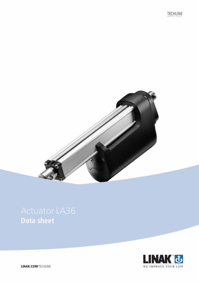
Actuator LA36Data sheet
LINAK.COM/TECHLINE
This TECHLINE® actuator comes with IC - Integrated controller.
For more information on our IC options, please see: www.linak.com/techline
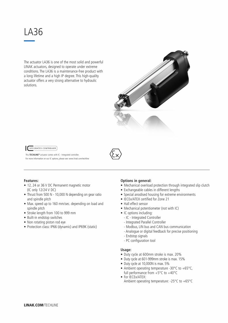
The actuator LA36 is one of the most solid and powerful LINAK actuators, designed to operate under extreme conditions. The LA36 is a maintenance-free product with a long lifetime and a high IP degree. This high-quality actuator offers a very strong alternative to hydraulic solutions.
Features:• 12, 24 or 36 V DC Permanent magnetic motor (IC only 12/24 V DC)• Thrust from 500 N - 10,000 N depending on gear ratio and spindle pitch• Max. speed up to 160 mm/sec. depending on load and spindle pitch• Stroke length from 100 to 999 mm• Built-in endstop switches• Non rotating piston rod eye• Protection class: IP66 (dynamic) and IP69K (static)
Options in general:• Mechanical overload protection through integrated slip clutch• Exchangeable cables in different lengths• Special anodised housing for extreme environments• IECEx/ATEX certified for Zone 21• Hall effect sensor• Mechanical potentiometer (not with IC)• IC options including: - IC - Integrated Controller - Integrated Parallel Controller - Modbus, LIN bus and CAN bus communication - Analogue or digital feedback for precise positioning - Endstop signals - PC configuration tool
Usage:• Duty cycle at 600mm stroke is max. 20%• Duty cycle at 601-999mm stroke is max. 15%• Duty cycle at 10,000N is max. 5%• Ambient operating temperature -30°C to +65°C, full performance from +5°C to +40°C• For IECEx/ATEX: Ambient operating temperature: -25°C to +65°C
LINAK.COM/TECHLINE
LA36
Page 3 of 40
Chapter 1
Specifications ........................................................................................................................................................ 3
Technical specifications.......................................................................................................................................... 4
LA36 Load versus Stroke Length ............................................................................................................................. 5
Stroke and built-in tolerances ................................................................................................................................. 5
LA36 Dimensions .................................................................................................................................................. 6
Built-in dimensions ................................................................................................................................................. 7
LA36 Piston Rod Eyes .......................................................................................................................................... 8-9
LA36 Back fixtures ......................................................................................................................................... 10-11
LA36 Back fixture orientation .............................................................................................................................. 12
Manual hand crank .............................................................................................................................................. 13
Cable dimensions ............................................................................................................................................13-14
Y-cable dimensions ...................................................................................................................................... 13
Power cable dimensions ............................................................................................................................... 14
Signal cable dimensions ............................................................................................................................... 14
Speed and current curves................................................................................................................................ 15-17
Chapter 2
I/O specifications:
Actuator without feedback .......................................................................................................................... 18
Actuator with:
Endstop signal output .............................................................................................................................. 18
Endstop signals and relative positioning - Dual Hall .................................................................................... 19
Endstop signals and relative positioning -Single Hall .................................................................................... 20
Endstop signals and absolute positioning - Analogue feedback ..................................................................... 21
Endstop signals and absolute positioning - Mechanical potentiometer feedback ............................................ 22
Endstop signals and absolute positioning - PWM......................................................................................... 23
IC Basic ................................................................................................................................................... 24
IC Advanced - with BusLink ................................................................................................................. 25-26
Parallel ..................................................................................................................................................... 27
CAN bus .................................................................................................................................................. 28
IC options overview .........................................................................................................................................................29
Feedback configurations available for IC Basic, IC Advanced and Parallel .................................................................... 30
Actuator configurations available for IC Basic, IC Advanced and Parallel ..................................................................... 31
System combination possibilities for LA36 IC Advanced ......................................................................................... 32
Chapter 3
Environmental tests - Climatic .......................................................................................................................... 33-34
Environmental tests - Mechanical ........................................................................................................................... 35
Environmental tests - Electrical ............................................................................................................................... 36
Contents
Page 4 of 40
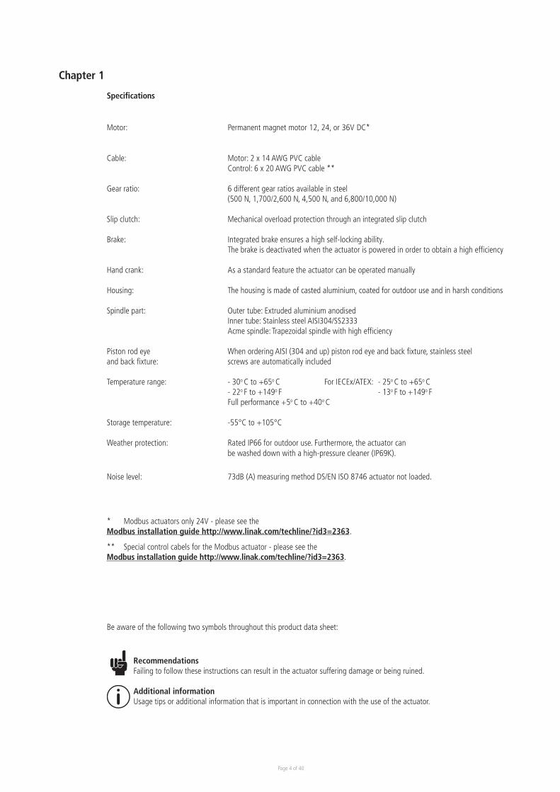
Motor: Permanent magnet motor 12, 24, or 36V DC*
Cable: Motor: 2 x 14 AWG PVC cable Control: 6 x 20 AWG PVC cable **
Gear ratio: 6 different gear ratios available in steel (500 N, 1,700/2,600 N, 4,500 N, and 6,800/10,000 N)
Slip clutch: Mechanical overload protection through an integrated slip clutch
Brake: Integrated brake ensures a high self-locking ability. The brake is deactivated when the actuator is powered in order to obtain a high efficiency
Hand crank: As a standard feature the actuator can be operated manually
Housing: The housing is made of casted aluminium, coated for outdoor use and in harsh conditions
Spindle part: Outer tube: Extruded aluminium anodised Inner tube: Stainless steel AISI304/SS2333 Acme spindle: Trapezoidal spindle with high efficiency
Piston rod eye When ordering AISI (304 and up) piston rod eye and back fixture, stainless steel and back fixture: screws are automatically included
Temperature range: - 30o C to +65o C For IECEx/ATEX: - 25o C to +65o C - 22o F to +149o F - 13o F to +149o F Full performance +5o C to +40o C
Storage temperature: -55°C to +105°C
Weather protection: Rated IP66 for outdoor use. Furthermore, the actuator can be washed down with a high-pressure cleaner (IP69K).
Noise level: 73dB (A) measuring method DS/EN ISO 8746 actuator not loaded.
* Modbus actuators only 24V - please see the Modbus installation guide http://www.linak.com/techline/?id3=2363.
** Special control cabels for the Modbus actuator - please see the Modbus installation guide http://www.linak.com/techline/?id3=2363.
Be aware of the following two symbols throughout this product data sheet:
RecommendationsFailing to follow these instructions can result in the actuator suffering damage or being ruined.
Additional informationUsage tips or additional information that is important in connection with the use of the actuator.
Chapter 1
Specifications
Page 5 of 40
Order number Push max.(N)
Pull max.(N)
*Self-lock min. (N)
Push
*Self-lock min. (N) Pull
Pitch (mm/spindle rev.)
*Typical speed (mm/s)Load
Standard stroke lengths (mm)
In steps of 50 mm
*Typical amp. (A)
12 V
No Full No load Full load
36080xxxxxxAxxxxHxxxxxxxxxxx 10000 10000 13000 13000 8 11 7 100 - 999** 4.5 22
36120xxxxxxAxxxxFxxxxxxxxxxx 2600 2600 3400 3400 12 40.7 30.6 100 - 999 4.5 21
36120xxxxxxAxxxxGxxxxxxxxxxx 4500 4500 5800 5800 12 23.1 17.8 100 - 999** 4.5 20.7
36120xxxxxxAxxxxHxxxxxxxxxxx 6800 6800 8800 8800 12 15.5 11.9 100 - 999** 4.5 21
36200xxxxxxAxxxxFxxxxxxxxxxx 1700 1700 2200 2200 20 68 52 100 - 999 4.5 22
36200xxxxxxAxxxxExxxxxxxxxxx 500*** 500*** 1000 1000 20 160 135 100 - 999 4.5 20
Technical specifications
LA36 with 24V motor
Order number Push max.(N)
Pull max.(N)
*Self-lockmin. (N)
Push
*Self-lockmin. (N) Pull
Pitch (mm/spindle rev.)
*Typical speed (mm/s)Load
Standard stroke lengths (mm)
In steps of 50 mm
*Typical amp.(A)
24 V
No Full No load Full load
36080xxxxxxBxxxxHxxxxxxxxxxx 10000 10000 13000 13000 8 11 7 100 - 999** 2.4 10.4
36120xxxxxxBxxxxFxxxxxxxxxxx 2600 2600 3400 3400 12 41 32.3 100 - 999 2.4 10.4
36120xxxxxxBxxxxGxxxxxxxxxxx 4500 4500 5800 5800 12 23.3 18.9 100 - 999** 2.4 10.2
36120xxxxxxBxxxxHxxxxxxxxxxx 6800 6800 8800 8800 12 15.7 12.7 100 - 999** 2.4 10.3
36200xxxxxxBxxxxFxxxxxxxxxxx 1700 1700 2200 2200 20 68 52 100 - 999 2.4 10.3
36200xxxxxxBxxxxExxxxxxxxxxx 500*** 500*** 1000 1000 20 160 135 100 - 999 2.4 10.0
LA36 with 36V motor
Order number Push max.(N)
Pull max.(N)
*Self-lockmin. (N)
Push
*Self-lockmin. (N) Pull
Pitch (mm/spindle rev.)
*Typical speed (mm/s)Load
Standard stroke lengths (mm)
In steps of 50 mm
*Typical amp.(A)
36 V
No Full No load Full load
36080xxxxxxCxxxxHxxxxxxxxxxx 10000 10000 13000 13000 8 11 7 100 - 999** 2.0 8.0
36120xxxxxxCxxxxFxxxxxxxxxxx 2600 2600 3400 3400 12 41 33.5 100 - 999 2.0 8.0
36120xxxxxxCxxxxGxxxxxxxxxxx 4500 4500 5800 5800 12 23.3 19.1 100 - 999** 2.0 8.0
36120xxxxxxCxxxxHxxxxxxxxxxx 6800 6800 8800 8800 12 15.7 12.8 100 - 999** 2.0 8.0
36200xxxxxxCxxxxFxxxxxxxxxxx 1700 1700 2200 2200 20 68 52 100 - 999 2.0 8.0
36200xxxxxxCxxxxExxxxxxxxxxx 500*** 500*** 1000 1000 20 160 135 100 - 999 2.0 8.0
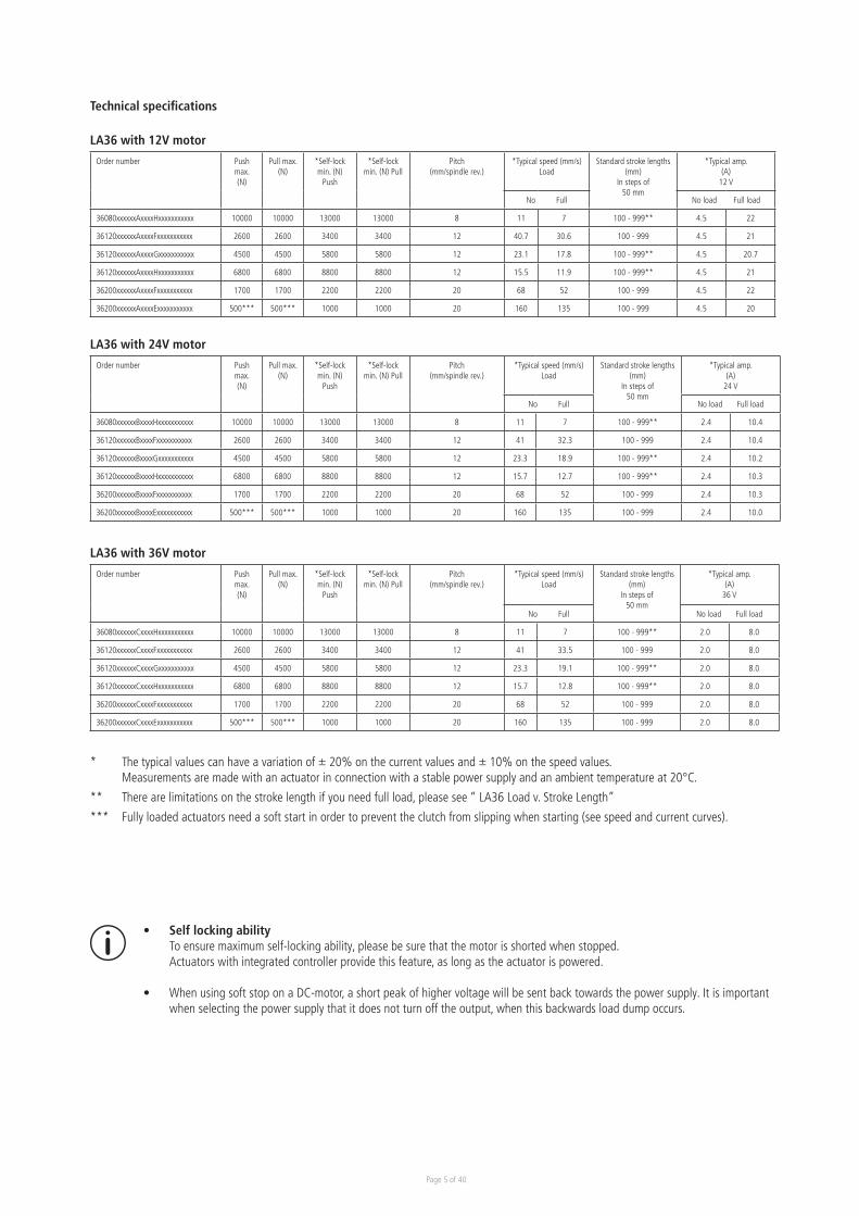
* The typical values can have a variation of ± 20% on the current values and ± 10% on the speed values. Measurements are made with an actuator in connection with a stable power supply and an ambient temperature at 20°C.
** There are limitations on the stroke length if you need full load, please see “ LA36 Load v. Stroke Length”
*** Fully loaded actuators need a soft start in order to prevent the clutch from slipping when starting (see speed and current curves).
LA36 with 12V motor
• Self locking ability To ensure maximum self-locking ability, please be sure that the motor is shorted when stopped. Actuators with integrated controller provide this feature, as long as the actuator is powered.
• When using soft stop on a DC-motor, a short peak of higher voltage will be sent back towards the power supply. It is important when selecting the power supply that it does not turn off the output, when this backwards load dump occurs.
Page 6 of 40
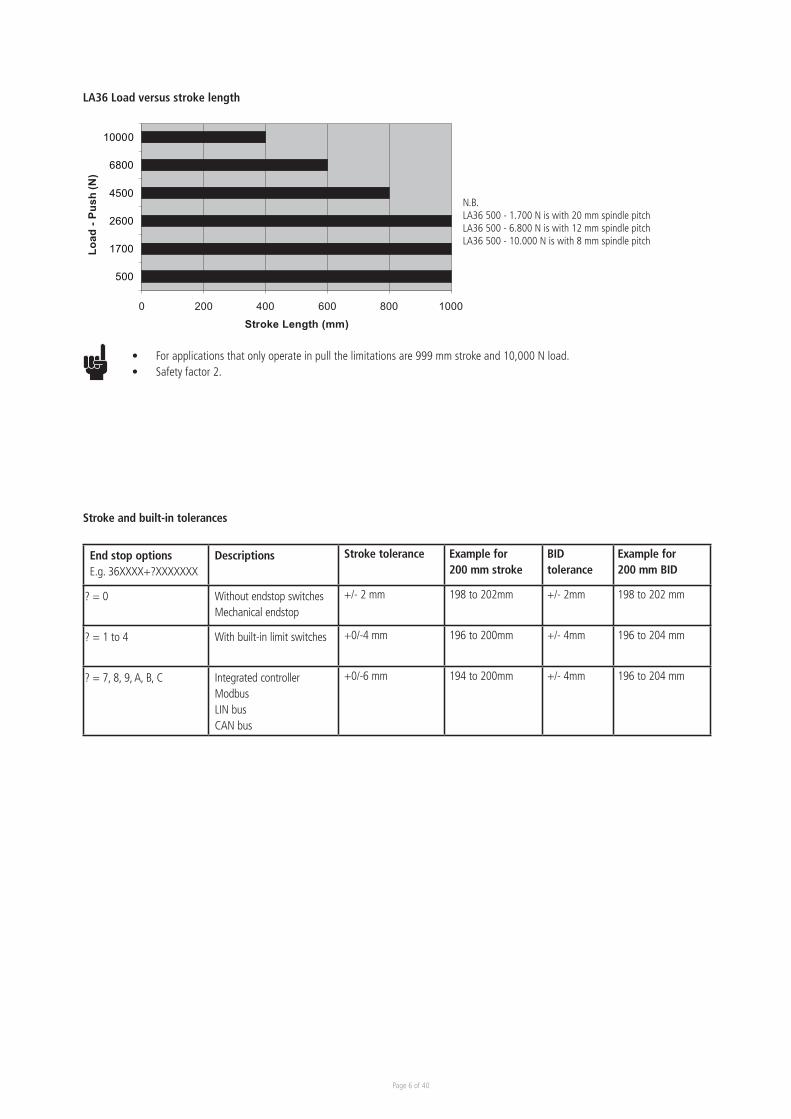
LA36 Load versus stroke length
0 200 400 600 800 1000
500
1700
2600
4500
6800
10000
Load
-Pus
h(N
)
Stroke Length (mm)
N.B. LA36 500 - 1.700 N is with 20 mm spindle pitchLA36 500 - 6.800 N is with 12 mm spindle pitchLA36 500 - 10.000 N is with 8 mm spindle pitch
• For applications that only operate in pull the limitations are 999 mm stroke and 10,000 N load.• Safety factor 2.
Stroke and built-in tolerances
End stop optionsE.g. 36XXXX+?XXXXXXX
Descriptions Stroke tolerance Example for 200 mm stroke
BID tolerance
Example for 200 mm BID
? = 0 Without endstop switchesMechanical endstop
+/- 2 mm 198 to 202mm +/- 2mm 198 to 202 mm
? = 1 to 4 With built-in limit switches +0/-4 mm 196 to 200mm +/- 4mm 196 to 204 mm
? = 7, 8, 9, A, B, C Integrated controllerModbusLIN busCAN bus
+0/-6 mm 194 to 200mm +/- 4mm 196 to 204 mm
Page 7 of 40
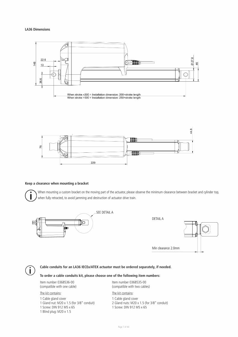
LA36 Dimensions
When STROKE >300 = Built-in dimension: 250+STROKE LENGTHWhen STROKE <300 = Built-in dimension: 200+STROKE LENGTH
_
Cable conduits for an LA36 IECEx/ATEX actuator must be ordered separately, if needed.
To order a cable conduits kit, please choose one of the following item numbers:
Item number 0368536-00 Item number 0368535-00 (compatible with one cable) (compatible with two cables)
The kit contains: The kit contains:
1 Cable gland cover 1 Cable gland cover1 Gland nut: M20 x 1.5 (for 3/8” conduit) 2 Gland nuts: M20 x 1.5 (for 3/8” conduit)1 Screw: DIN 912 M5 x 65 1 Screw: DIN 912 M5 x 651 Blind plug: M20 x 1.5
Keep a clearance when mounting a bracket
A
B
C
D
1 2 3 4 5 6
E
F
7 8
1 2 3 4
A
B
C
D
E
General Surface Character:
Name:
Updated:Producer:
General Tolerance:
Material:
Type:
No.:
Created by:
Approved by:
Modified by:
Product:
Color:
No. Of check dimensions (#):Format: Sheet: Scale: Volume:
Confidential: Property of LINAK A/S GROUP HEADQUARTER, DK-6430 NORDBORG, DENMARK Phone +45 73 15 15 15 ; FAX +45 74 45 80 48. Not to be handed over to, copied or used by third party.
WE IMPROVE YOUR LIFE
2D State:
3D State:
Min. clearence 2.0mm
Min. clearence 2.0mm
0362113-ALA36 Custom bracket - Clearance-
Concept/Iteration 2- Concept/Iteration 2-
- 2130530 mm³1:51/1A32018-06-13- Jannie Sølyst Jansen - Jannie Sølyst Jansen---
SEE DETAIL A
SEE DETAIL B
A
B
C
D
1 2 3 4 5 6
E
F
7 8
1 2 3 4
A
B
C
D
E
General Surface Character:
Name:
Updated:Producer:
General Tolerance:
Material:
Type:
No.:
Created by:
Approved by:
Modified by:
Product:
Color:
No. Of check dimensions (#):Format: Sheet: Scale: Volume:
Confidential: Property of LINAK A/S GROUP HEADQUARTER, DK-6430 NORDBORG, DENMARK Phone +45 73 15 15 15 ; FAX +45 74 45 80 48. Not to be handed over to, copied or used by third party.
WE IMPROVE YOUR LIFE
2D State:
3D State:
Min. clearence 2.0mm
Min. clearence 2.0mm
0362113-ALA36 Custom bracket - Clearance-
Concept/Iteration 2- Concept/Iteration 2-
- 2130530 mm³1:51/1A32018-06-13- Jannie Sølyst Jansen - Jannie Sølyst Jansen---
SEE DETAIL A
SEE DETAIL B
When mounting a custom bracket on the moving part of the actuator, please observe the minimum clearance between bracket and cylinder top,
when fully retracted, to avoid jamming and destruction of actuator drive train.
SEE DETAIL A
DETAIL A
Min clearance 2.0mm
Page 8 of 40
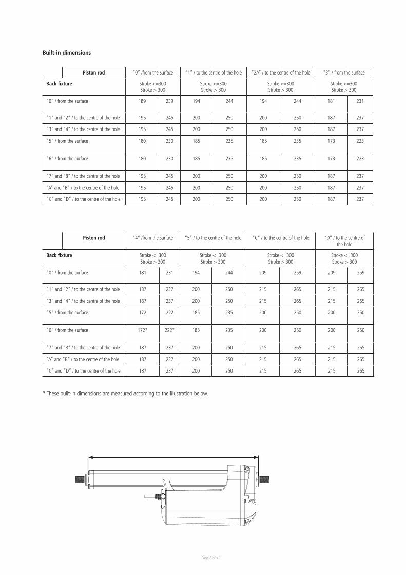
Built-in dimensions
* These built-in dimensions are measured according to the illustration below.
Piston rod “0” /from the surface “1” / to the centre of the hole “2A” / to the centre of the hole “3” / from the surface
Back fixture Stroke <=300 Stroke > 300
Stroke <=300 Stroke > 300
Stroke <=300 Stroke > 300
Stroke <=300 Stroke > 300
“0” / from the surface 189 239 194 244 194 244 181 231
“1” and “2” / to the centre of the hole 195 245 200 250 200 250 187 237
“3” and “4” / to the centre of the hole 195 245 200 250 200 250 187 237
“5” / from the surface 180 230 185 235 185 235 173 223
“6” / from the surface 180 230 185 235 185 235 173 223
“7” and “8” / to the centre of the hole 195 245 200 250 200 250 187 237
“A” and “B” / to the centre of the hole 195 245 200 250 200 250 187 237
“C” and “D” / to the centre of the hole 195 245 200 250 200 250 187 237
Piston rod “4” /from the surface “5” / to the centre of the hole “C” / to the centre of the hole “D” / to the centre of the hole
Back fixture Stroke <=300 Stroke > 300
Stroke <=300 Stroke > 300
Stroke <=300 Stroke > 300
Stroke <=300 Stroke > 300
“0” / from the surface 181 231 194 244 209 259 209 259
“1” and “2” / to the centre of the hole 187 237 200 250 215 265 215 265
“3” and “4” / to the centre of the hole 187 237 200 250 215 265 215 265
“5” / from the surface 172 222 185 235 200 250 200 250
“6” / from the surface 172* 222* 185 235 200 250 200 250
“7” and “8” / to the centre of the hole 187 237 200 250 215 265 215 265
“A” and “B” / to the centre of the hole 187 237 200 250 215 265 215 265
“C” and “D” / to the centre of the hole 187 237 200 250 215 265 215 265
Page 9 of 40
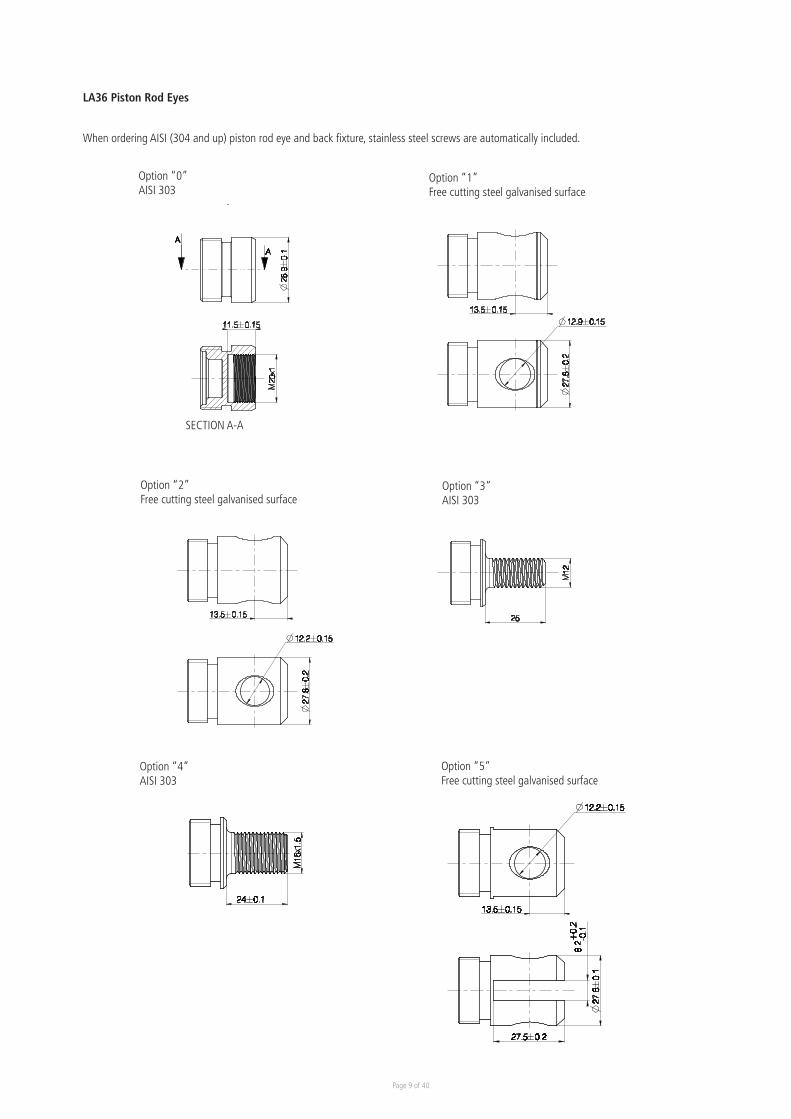
LA36 Piston Rod Eyes
When ordering AISI (304 and up) piston rod eye and back fixture, stainless steel screws are automatically included.
Option “0”AISI 303
Option “1”Free cutting steel galvanised surface
SECTION A-A
Option “2”Free cutting steel galvanised surface
Option “3”AISI 303
Option “4”AISI 303
Option “5”Free cutting steel galvanised surface
Page 10 of 40
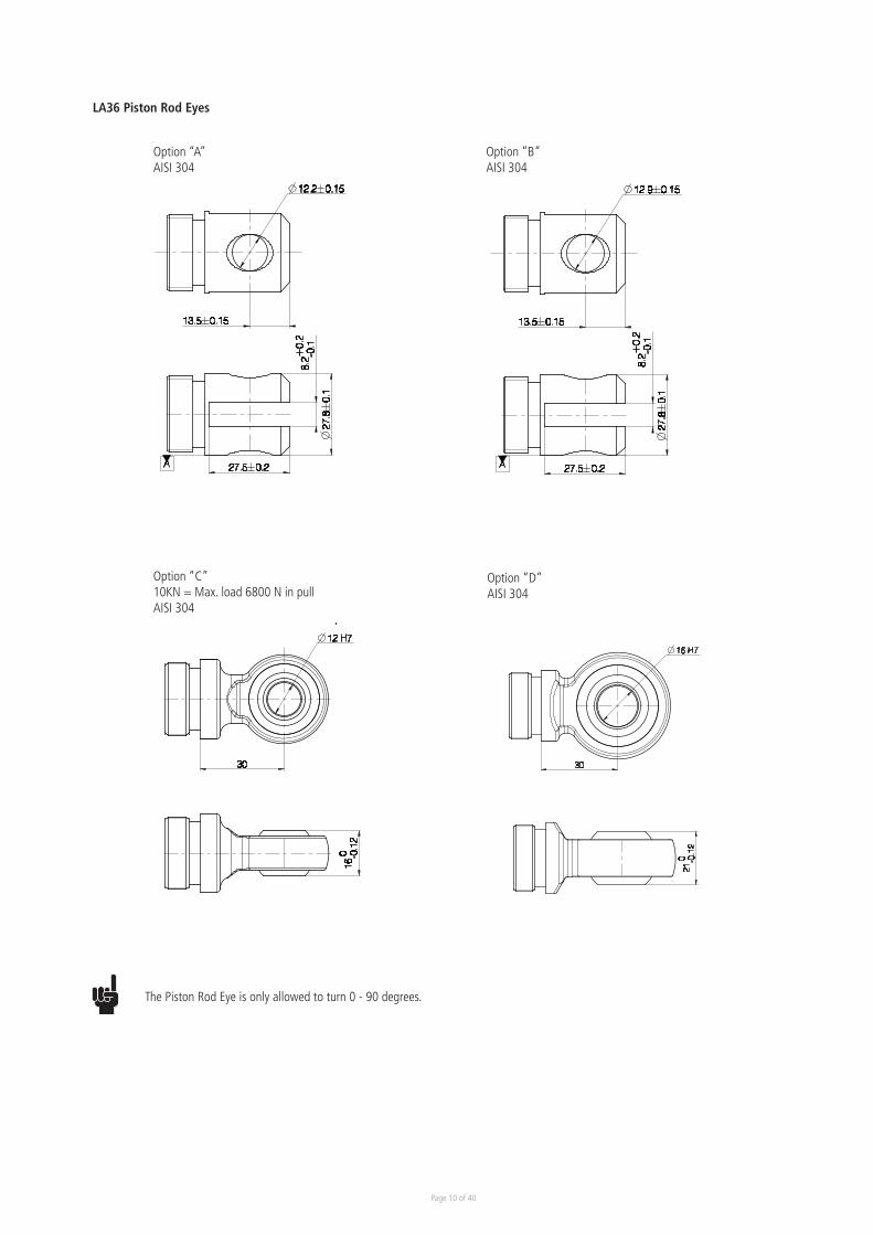
LA36 Piston Rod Eyes
Option “A”AISI 304
Option “B”AISI 304
Option “D”AISI 304
Option “C”10KN = Max. load 6800 N in pullAISI 304
The Piston Rod Eye is only allowed to turn 0 - 90 degrees.
Page 11 of 40
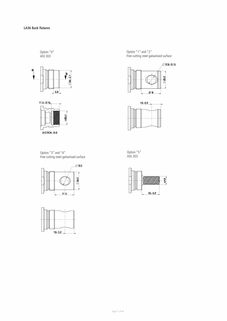
LA36 Back fixtures
Option “0”AISI 303
Option “1” and “2”Free cutting steel galvanised surface
Option “5”AISI 303
Option “3” and “4”Free cutting steel galvanised surface
Page 12 of 40
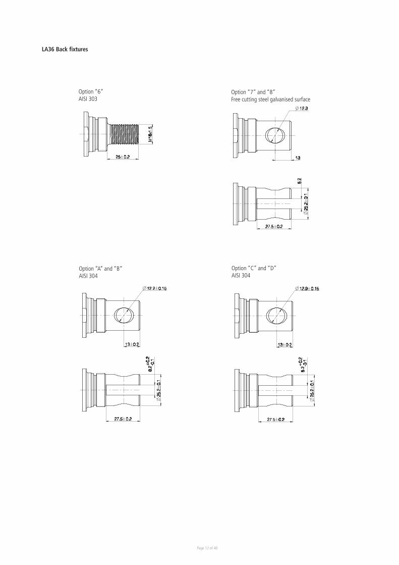
LA36 Back fixtures
Option “7” and “8”Free cutting steel galvanised surface
Option “6”AISI 303
Option “A” and “B”AISI 304
Option “C” and “D”AISI 304
Page 13 of 40
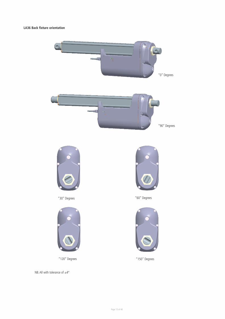
LA36 Back fixture orientation
“60” Degrees
“120” Degrees “150” Degrees
“30” Degrees
NB. All with tolerance of ±4°
“0” Degrees
“90” Degrees
Page 14 of 40
Cable dimensions
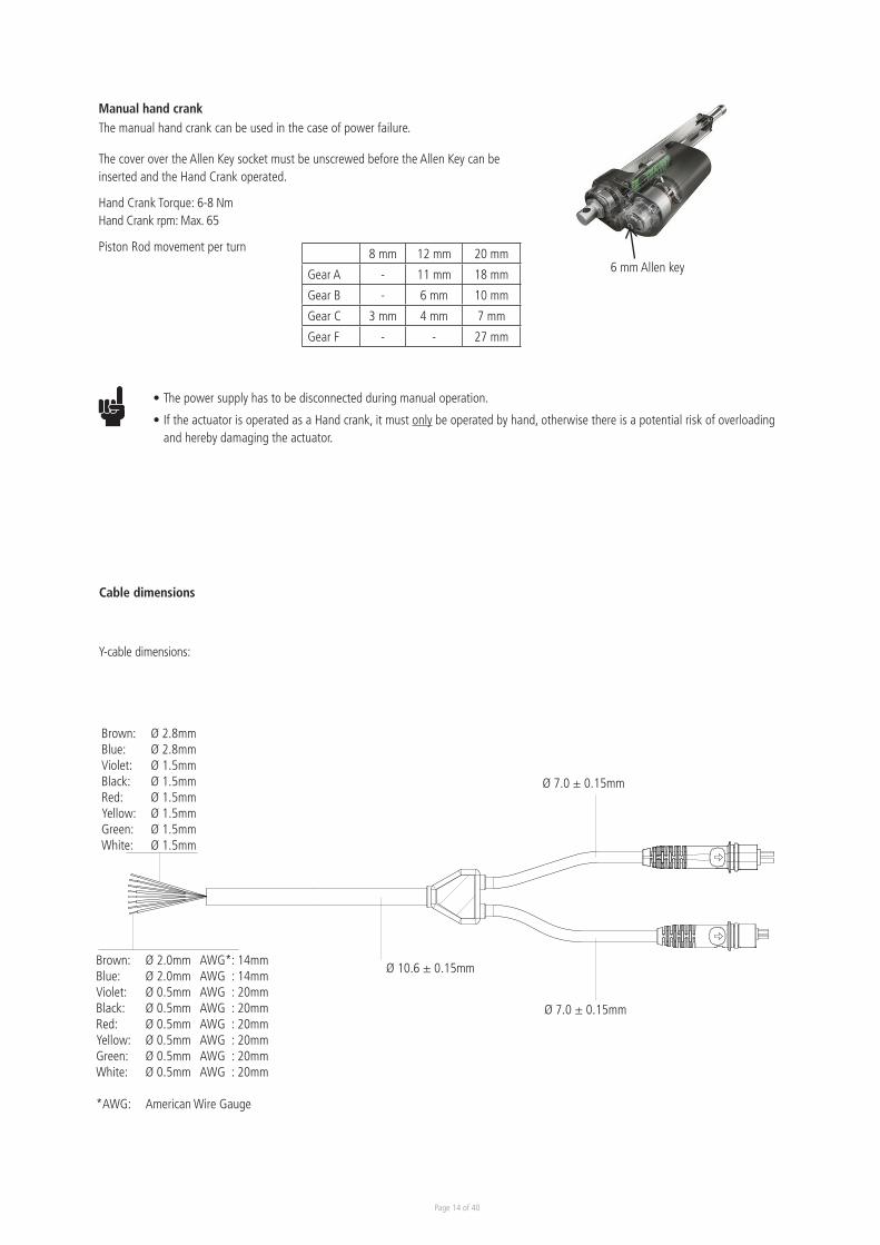
Y-cable dimensions:
Brown: Ø 2.8mmBlue: Ø 2.8mmViolet: Ø 1.5mmBlack: Ø 1.5mmRed: Ø 1.5mmYellow: Ø 1.5mmGreen: Ø 1.5mmWhite: Ø 1.5mm
Brown: Ø 2.0mm AWG*: 14mmBlue: Ø 2.0mm AWG : 14mmViolet: Ø 0.5mm AWG : 20mmBlack: Ø 0.5mm AWG : 20mmRed: Ø 0.5mm AWG : 20mmYellow: Ø 0.5mm AWG : 20mmGreen: Ø 0.5mm AWG : 20mmWhite: Ø 0.5mm AWG : 20mm
*AWG: American Wire Gauge
Ø 10.6 ± 0.15mm
Ø 7.0 ± 0.15mm
Ø 7.0 ± 0.15mm
The cover over the Allen Key socket must be unscrewed before the Allen Key can be inserted and the Hand Crank operated.
Hand Crank Torque: 6-8 NmHand Crank rpm: Max. 65
Piston Rod movement per turn
The manual hand crank can be used in the case of power failure.
6 mm Allen key
Manual hand crank
• The power supply has to be disconnected during manual operation.
• If the actuator is operated as a Hand crank, it must only be operated by hand, otherwise there is a potential risk of overloading and hereby damaging the actuator.
8 mm 12 mm 20 mm
Gear A - 11 mm 18 mm
Gear B - 6 mm 10 mm
Gear C 3 mm 4 mm 7 mm
Gear F - - 27 mm
Page 15 of 40
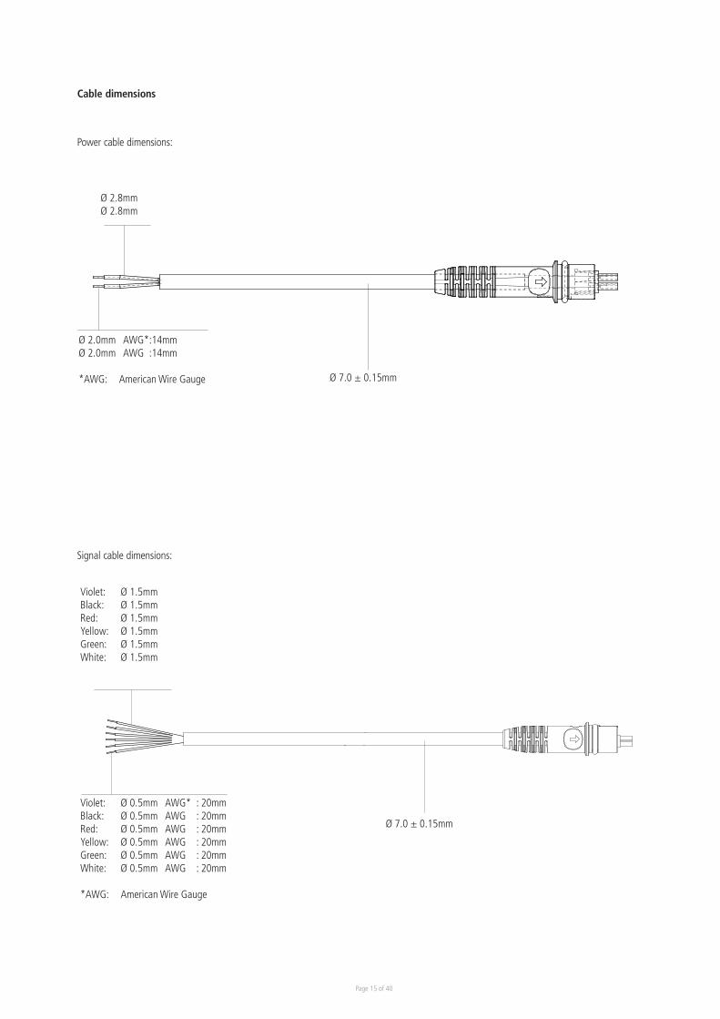
Power cable dimensions:
Signal cable dimensions:
Ø 2.8mmØ 2.8mm
Ø 2.0mm AWG*:14mmØ 2.0mm AWG :14mm
*AWG: American Wire Gauge Ø 7.0 ± 0.15mm
Violet: Ø 1.5mmBlack: Ø 1.5mmRed: Ø 1.5mmYellow: Ø 1.5mmGreen: Ø 1.5mmWhite: Ø 1.5mm
Violet: Ø 0.5mm AWG* : 20mmBlack: Ø 0.5mm AWG : 20mmRed: Ø 0.5mm AWG : 20mmYellow: Ø 0.5mm AWG : 20mmGreen: Ø 0.5mm AWG : 20mmWhite: Ø 0.5mm AWG : 20mm
*AWG: American Wire Gauge
Ø 7.0 ± 0.15mm
Cable dimensions
Page 16 of 40
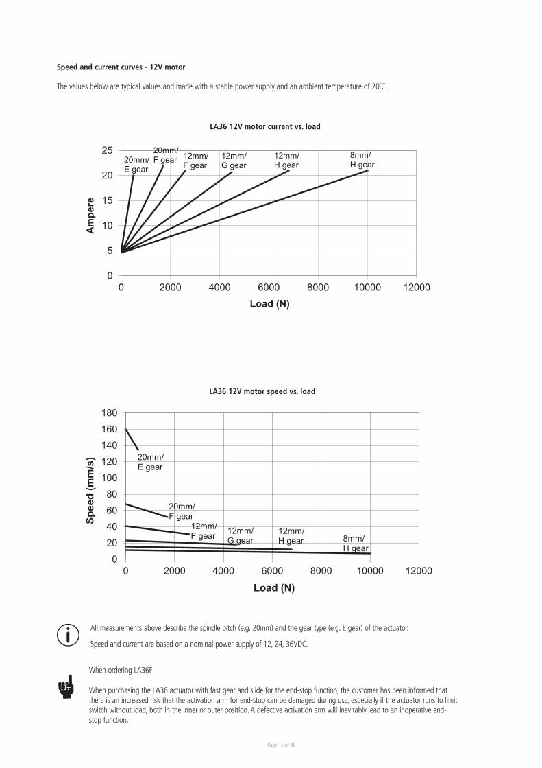
Speed and current curves - 12V motor
The values below are typical values and made with a stable power supply and an ambient temperature of 20˚C.
All measurements above describe the spindle pitch (e.g. 20mm) and the gear type (e.g. E gear) of the actuator.
Speed and current are based on a nominal power supply of 12, 24, 36VDC.
0
5
10
15
20
25
0 2000 4000 6000 8000 10000 12000
Ampe
re
Load (N)
LA36 12V motor current vs. load
8mm/H gear
12mm/G gear
12mm/ H gear
20mm/F gear 12mm/
F gear20mm/E gear
LA36 12V motor current vs. load
020406080
100120140160180
0 2000 4000 6000 8000 10000 12000
Spee
d (m
m/s
)
Load (N)
LA36 12V motor speed vs. load
12mm/F gear 12mm/
G gear12mm/H gear
20mm/F gear
20mm/E gear
8mm/H gear
LA36 12V motor speed vs. load
When ordering LA36F
When purchasing the LA36 actuator with fast gear and slide for the end-stop function, the customer has been informed that there is an increased risk that the activation arm for end-stop can be damaged during use, especially if the actuator runs to limit switch without load, both in the inner or outer position. A defective activation arm will inevitably lead to an inoperative end-stop function.
Page 17 of 40
0
2
4
6
8
10
12
0 2000 4000 6000 8000 10000
Ampe
re
Load (N)
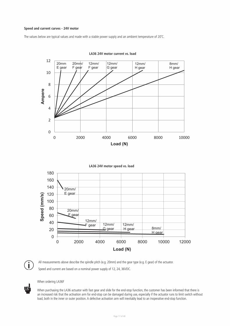
LA36 24V motor current vs. load
8mm/H gear
12mm/H gear
12mm/G gear
12mm/F gear
20mm/F gear
20mmE gear
LA36 24V motor current vs. load
020406080
100120140160180
0 2000 4000 6000 8000 10000 12000
Spee
d (m
m/s
)
Load (N)
LA36 24V motor speed vs. load
12mm/F gear 12mm/
G gear12mm/H gear
20mm/F gear
20mm/E gear
8mm/H gear
LA36 24V motor speed vs. load
All measurements above describe the spindle pitch (e.g. 20mm) and the gear type (e.g. E gear) of the actuator.
Speed and current are based on a nominal power supply of 12, 24, 36VDC.
Speed and current curves - 24V motor
The values below are typical values and made with a stable power supply and an ambient temperature of 20˚C.
When ordering LA36F
When purchasing the LA36 actuator with fast gear and slide for the end-stop function, the customer has been informed that there is an increased risk that the activation arm for end-stop can be damaged during use, especially if the actuator runs to limit switch without load, both in the inner or outer position. A defective activation arm will inevitably lead to an inoperative end-stop function.
Page 18 of 40
0
2
4
6
8
10
0 2000 4000 6000 8000 10000
Ampe
re
Load (N)
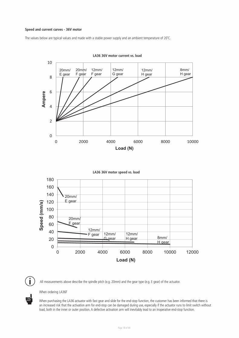
LA36 36V motor current vs. load
8mm/H gear
12mm/H gear
12mm/G gear
12mm/F gear
20mm/F gear
20mm/E gear
LA36 36V motor current vs. load
020406080
100120140160180
0 2000 4000 6000 8000 10000 12000
Spee
d (m
m/s
)
Load (N)
LA36 36V motor speed vs. load
12mm/F gear 12mm/
G gear12mm/H gear
20mm/F gear
20mm/E gear
8mm/H gear
LA36 36V motor speed vs. load
All measurements above describe the spindle pitch (e.g. 20mm) and the gear type (e.g. E gear) of the actuator.
Speed and current curves - 36V motor
The values below are typical values and made with a stable power supply and an ambient temperature of 20˚C.
When ordering LA36F
When purchasing the LA36 actuator with fast gear and slide for the end-stop function, the customer has been informed that there is an increased risk that the activation arm for end-stop can be damaged during use, especially if the actuator runs to limit switch without load, both in the inner or outer position. A defective activation arm will inevitably lead to an inoperative end-stop function.

Page 19 of 40
I/O specifications: Actuator without feedback
Input/Output Specification Comments
Description Permanent magnetic DC motor.
Brown 12, 24 or 36VDC (+/-)
12V ± 20%24V ± 10%36V ± 10%
Under normal conditions: 12V, max. 26A depending on load24V, max. 13A depending on load36V, max. 10A depending on load
To extend actuator:Connect Brown to positive
To retract actuator:Connect Brown to negative
Blue To extend actuator:Connect Blue to negative
To retract actuator:Connect Blue to positive
Red Not to be connected
Black Not to be connected
Green Not to be connected
Yellow Not to be connected
Violet Not to be connected
White Not to be connected
I/O specifications: Actuator with endstop signal output
Input/Output Specification Comments
Description The actuator can be equipped with electronically con-trolled endstop signals out.
Brown 12, 24 or 36VDC (+/-)
12V ± 20%24V ± 10%36V ± 10%
Under normal conditions: 12V, max. 26A depending on load24V, max. 13A depending on load36V, max. 10A depending on load
To extend actuator:Connect Brown to positive
To retract actuator:Connect Brown to negative
Blue To extend actuator:Connect Blue to negative
To retract actuator:Connect Blue to positive
Red Signal power supply (+)12-24VDC Current consumption:
Max. 40mA, also when the actuator is not runningBlack Signal power supply GND (-)
Green Endstop signal out Output voltage min. VIN - 2V Source current max. 100mANOT potential freeYellow Endstop signal in
Violet Not to be connected
White Not to be connected
INOUT
Chapter 2
Page 20 of 40
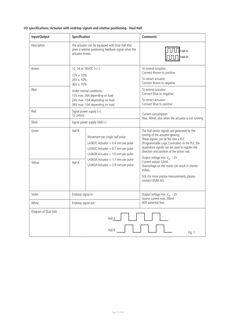
I/O specifications: Actuator with endstop signals and relative positioning - Dual Hall
Input/Output Specification Comments
Description The actuator can be equipped with Dual Hall that gives a relative positioning feedback signal when the actuator moves.
Brown 12, 24 or 36VDC (+/-)
12V ± 20%24V ± 10%36V ± 10%
Under normal conditions: 12V, max. 26A depending on load24V, max. 13A depending on load36V, max. 10A depending on load
To extend actuator:Connect Brown to positive
To retract actuator:Connect Brown to negative
Blue To extend actuator:Connect Blue to negative
To retract actuator:Connect Blue to positive
Red Signal power supply (+)12-24VDC Current consumption:
Max. 40mA, also when the actuator is not runningBlack Signal power supply GND (-)
Green Hall B
Movement per single hall pulse:
LA362C Actuator = 0.4 mm per pulse
LA363C Actuator = 0.7 mm per pulse
LA363B Actuator = 1.0 mm per pulse
LA363A Actuator = 1.7 mm per pulse
LA365A Actuator = 2.9 mm per pulse
The Hall sensor signals are generated by the turning of the actuator gearing. These signals can be fed into a PLC (Programmable Logic Controller). In the PLC the quadrature signals can be used to register the direction and position of the piston rod.
Output voltage min. VIN - 2VCurrent output 12mA Overvoltage on the motor can result in shorter pulses.
N.B. For more precise measurements, please contact LINAK A/S.
Yellow Hall A
Violet Endstop signal in Output voltage min. VIN - 2V Source current max. 30mANOT potential freeWhite Endstop signal out
Diagram of Dual Hall:
Fig. 1Hall B
Hall A
Page 21 of 40
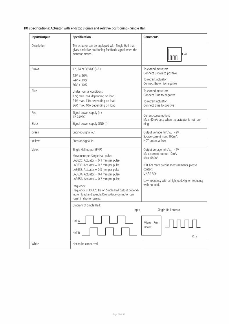
I/O specifications: Actuator with endstop signals and relative positioning - Single Hall
Input/Output Specification Comments
Description The actuator can be equipped with Single Hall that gives a relative positioning feedback signal when the actuator moves.
Brown 12, 24 or 36VDC (+/-)
12V ± 20%24V ± 10%36V ± 10%
Under normal conditions: 12V, max. 26A depending on load24V, max. 13A depending on load36V, max. 10A depending on load
To extend actuator:Connect Brown to positive
To retract actuator:Connect Brown to negative
Blue To extend actuator:Connect Blue to negative
To retract actuator:Connect Blue to positive
Red Signal power supply (+)12-24VDC
Current consumption:Max. 40mA, also when the actuator is not run-ningBlack Signal power supply GND (-)
Green Endstop signal out Output voltage min. VIN - 2V Source current max. 100mANOT potential freeYellow Endstop signal in
Violet Single Hall output (PNP)
Movement per Single Hall pulse:LA362C: Actuator = 0.1 mm per pulseLA363C: Actuator = 0.2 mm per pulseLA363B: Actuator = 0.3 mm per pulseLA363A: Actuator = 0.4 mm per pulseLA365A: Actuator = 0.7 mm per pulse
Frequency: Frequency is 30-125 Hz on Single Hall output depend-ing on load and spindle.Overvoltage on motor can result in shorter pulses.
Output voltage min. VIN - 2V Max. current output: 12mAMax. 680nF
N.B. For more precise measurements, please contact LINAK A/S.
Low frequency with a high load.Higher frequency with no load.
Diagram of Single Hall:
White Not to be connected
Fig. 2
Micro - Pro-cessor
Input Single Hall output
Hall B
Hall A
Page 22 of 40
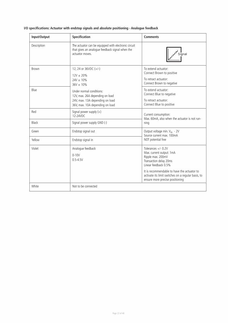
I/O specifications: Actuator with endstop signals and absolute positioning - Analogue feedback
Input/Output Specification Comments
Description The actuator can be equipped with electronic circuit that gives an analogue feedback signal when the actuator moves.
Brown 12, 24 or 36VDC (+/-)
12V ± 20%24V ± 10%36V ± 10%
Under normal conditions: 12V, max. 26A depending on load24V, max. 13A depending on load36V, max. 10A depending on load
To extend actuator:Connect Brown to positive
To retract actuator:Connect Brown to negative
Blue To extend actuator:Connect Blue to negative
To retract actuator:Connect Blue to positive
Red Signal power supply (+)12-24VDC
Current consumption:Max. 60mA, also when the actuator is not run-ningBlack Signal power supply GND (-)
Green Endstop signal out Output voltage min. VIN - 2V Source current max. 100mANOT potential freeYellow Endstop signal in
Violet Analogue feedback
0-10V 0.5-4.5V
Tolerances +/- 0.2VMax. current output: 1mARipple max. 200mVTransaction delay 20msLinear feedback 0.5%
It is recommendable to have the actuator to activate its limit switches on a regular basis, to ensure more precise positioning
White Not to be connected
Page 23 of 40
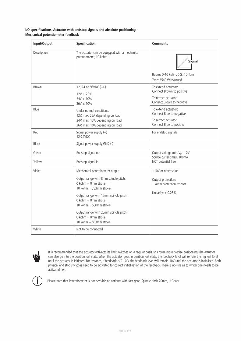
I/O specifications: Actuator with endstop signals and absolute positioning - Mechanical potentiometer feedback
Input/Output Specification Comments
Description The actuator can be equipped with a mechanical potentiometer, 10 kohm.
Bourns 0-10 kohm, 5%, 10-Turn
Type: 3540 Wirewound
Brown 12, 24 or 36VDC (+/-)
12V ± 20%24V ± 10%36V ± 10%
Under normal conditions: 12V, max. 26A depending on load24V, max. 13A depending on load36V, max. 10A depending on load
To extend actuator:Connect Brown to positive
To retract actuator:Connect Brown to negative
Blue To extend actuator:Connect Blue to negative
To retract actuator:Connect Blue to positive
Red Signal power supply (+)12-24VDC
For endstop signals
Black Signal power supply GND (-)
Green Endstop signal out Output voltage min. VIN - 2V Source current max. 100mANOT potential freeYellow Endstop signal in
Violet Mechanical potentiometer output
Output range with 8mm spindle pitch: 0 kohm = 0mm stroke10 kohm = 333mm stroke
Output range with 12mm spindle pitch: 0 kohm = 0mm stroke10 kohm = 500mm stroke
Output range with 20mm spindle pitch: 0 kohm = 0mm stroke10 kohm = 833mm stroke
+10V or other value
Output protection: 1 kohm protection resistor
Linearity: ± 0.25%
White Not to be connected
Please note that Potentiometer is not possible on variants with fast gear (Spindle pitch 20mm, H Gear).
It is recommended that the actuator activates its limit switches on a regular basis, to ensure more precise positioning. The actuator can also go into the position lost state. When the actuator goes in position lost state, the feedback level will remain the highest level until the actuator is initiated. For instance, if feedback is 0-10 V, the feedback level will remain 10V until the actuator is initialised. Both physical end stop switches need to be activated for correct initialisation of the feedback. There is no rule as to which one needs to be activated first.
Page 24 of 40
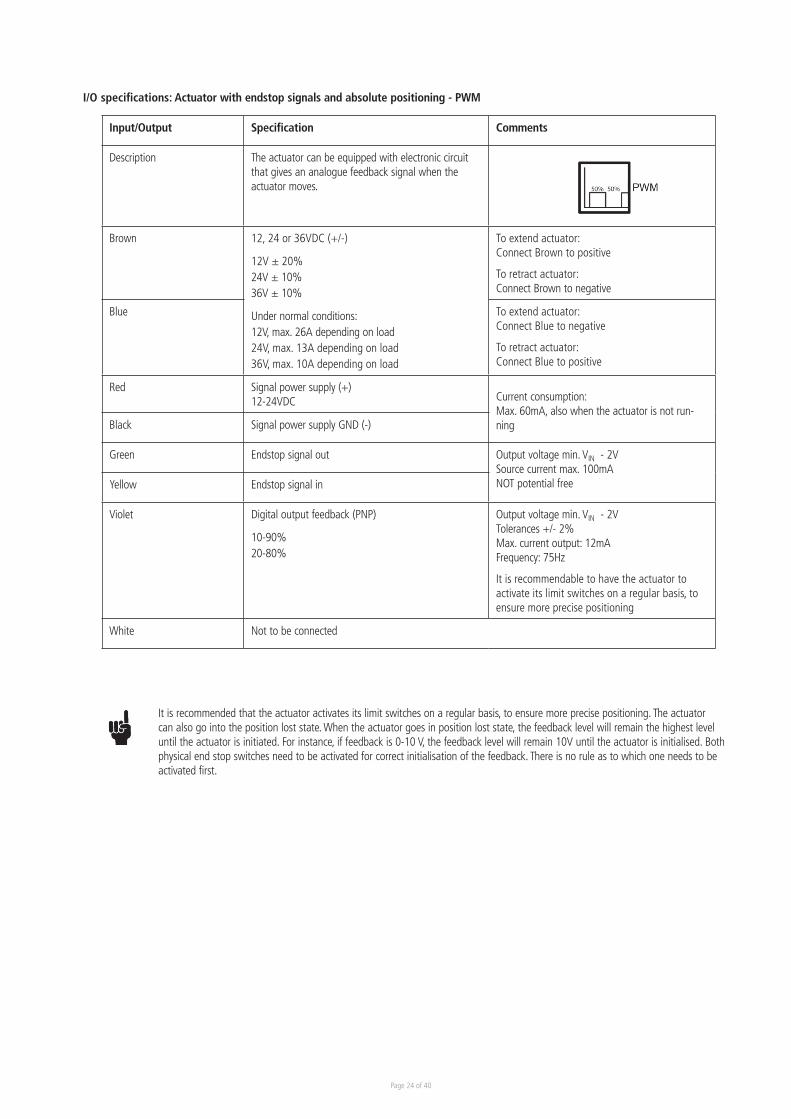
I/O specifications: Actuator with endstop signals and absolute positioning - PWM
Input/Output Specification Comments
Description The actuator can be equipped with electronic circuit that gives an analogue feedback signal when the actuator moves.
Brown 12, 24 or 36VDC (+/-)
12V ± 20%24V ± 10%36V ± 10%
Under normal conditions: 12V, max. 26A depending on load24V, max. 13A depending on load36V, max. 10A depending on load
To extend actuator:Connect Brown to positive
To retract actuator:Connect Brown to negative
Blue To extend actuator:Connect Blue to negative
To retract actuator:Connect Blue to positive
Red Signal power supply (+)12-24VDC
Current consumption:Max. 60mA, also when the actuator is not run-ningBlack Signal power supply GND (-)
Green Endstop signal out Output voltage min. VIN - 2V Source current max. 100mANOT potential freeYellow Endstop signal in
Violet Digital output feedback (PNP)
10-90% 20-80%
Output voltage min. VIN - 2VTolerances +/- 2%Max. current output: 12mAFrequency: 75Hz
It is recommendable to have the actuator to activate its limit switches on a regular basis, to ensure more precise positioning
White Not to be connected
It is recommended that the actuator activates its limit switches on a regular basis, to ensure more precise positioning. The actuator can also go into the position lost state. When the actuator goes in position lost state, the feedback level will remain the highest level until the actuator is initiated. For instance, if feedback is 0-10 V, the feedback level will remain 10V until the actuator is initialised. Both physical end stop switches need to be activated for correct initialisation of the feedback. There is no rule as to which one needs to be activated first.
Page 25 of 40
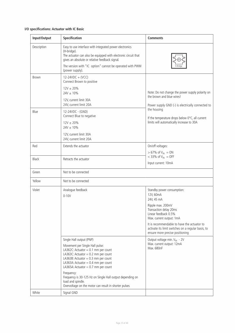
I/O specifications: Actuator with IC Basic
Input/Output Specification Comments
Description Easy to use interface with integrated power electronics (H-bridge).The actuator can also be equipped with electronic circuit that gives an absolute or relative feedback signal.
The version with “IC option” cannot be operated with PWM (power supply).
Brown 12-24VDC + (VCC) Connect Brown to positive
12V ± 20%24V ± 10%
12V, current limit 30A24V, current limit 20A
Note: Do not change the power supply polarity on the brown and blue wires!
Power supply GND (-) is electrically connected to the housing
If the temperature drops below 0°C, all current limits will automatically increase to 30A
Blue 12-24VDC - (GND) Connect Blue to negative
12V ± 20%24V ± 10%
12V, current limit 30A24V, current limit 20A
Red Extends the actuator On/off voltages:
> 67% of VIN = ON< 33% of VIN = OFF
Input current: 10mABlack Retracts the actuator
Green Not to be connected
Yellow Not to be connected
Violet Analogue feedback
0-10V
Standby power consumption: 12V, 60mA24V, 45 mA
Ripple max. 200mVTransaction delay 20msLinear feedback 0.5%Max. current output: 1mA
It is recommendable to have the actuator to activate its limit switches on a regular basis, to ensure more precise positioning
Single Hall output (PNP)
Movement per Single Hall pulse:LA362C: Actuator = 0.1 mm per countLA363C: Actuator = 0.2 mm per countLA363B: Actuator = 0.3 mm per countLA363A: Actuator = 0.4 mm per countLA365A: Actuator = 0.7 mm per count
Frequency: Frequency is 30-125 Hz on Single Hall output depending on load and spindle. Overvoltage on the motor can result in shorter pulses
Output voltage min. VIN - 2V Max. current output: 12mAMax. 680nF
White Signal GND
M
H-Bridge
Page 26 of 40
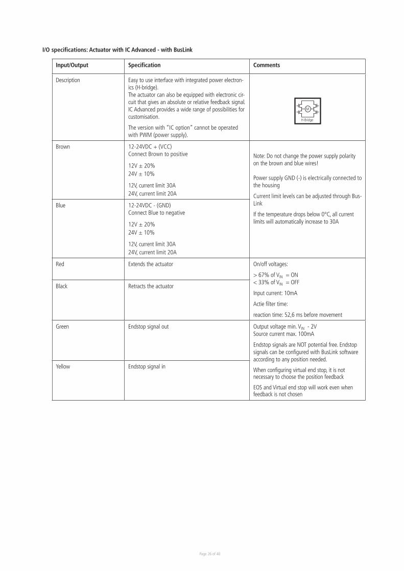
I/O specifications: Actuator with IC Advanced - with BusLink
Input/Output Specification Comments
Description Easy to use interface with integrated power electron-ics (H-bridge).The actuator can also be equipped with electronic cir-cuit that gives an absolute or relative feedback signal.IC Advanced provides a wide range of possibilities for customisation.
The version with “IC option” cannot be operated with PWM (power supply).
Brown 12-24VDC + (VCC) Connect Brown to positive
12V ± 20%24V ± 10%
12V, current limit 30A24V, current limit 20A
Note: Do not change the power supply polarity on the brown and blue wires!
Power supply GND (-) is electrically connected to the housing
Current limit levels can be adjusted through Bus-Link
If the temperature drops below 0°C, all current limits will automatically increase to 30A
Blue 12-24VDC - (GND) Connect Blue to negative
12V ± 20%24V ± 10%
12V, current limit 30A24V, current limit 20A
Red Extends the actuator On/off voltages:
> 67% of VIN = ON< 33% of VIN = OFF
Input current: 10mA
Actie filter time:
reaction time: 52,6 ms before movement
Black Retracts the actuator
Green Endstop signal out Output voltage min. VIN - 2V Source current max. 100mA
Endstop signals are NOT potential free. Endstop signals can be configured with BusLink software according to any position needed.
When configuring virtual end stop, it is not necessary to choose the position feedback
EOS and Virtual end stop will work even when feedback is not chosen
Yellow Endstop signal in
M
H-Bridge
Page 27 of 40
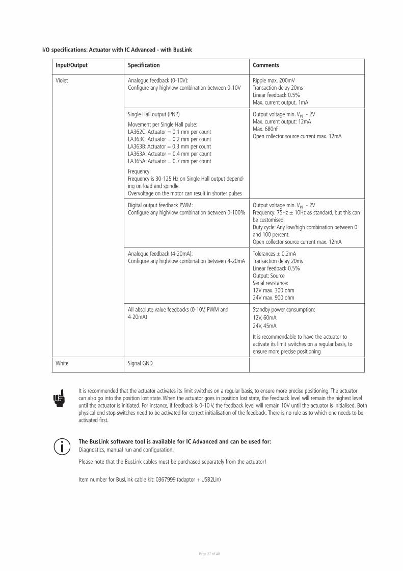
I/O specifications: Actuator with IC Advanced - with BusLink
Input/Output Specification Comments
Violet Analogue feedback (0-10V):Configure any high/low combination between 0-10V
Ripple max. 200mVTransaction delay 20msLinear feedback 0.5%Max. current output. 1mA
Single Hall output (PNP)
Movement per Single Hall pulse:LA362C: Actuator = 0.1 mm per countLA363C: Actuator = 0.2 mm per countLA363B: Actuator = 0.3 mm per countLA363A: Actuator = 0.4 mm per countLA365A: Actuator = 0.7 mm per count
Frequency: Frequency is 30-125 Hz on Single Hall output depend-ing on load and spindle. Overvoltage on the motor can result in shorter pulses
Output voltage min. VIN - 2VMax. current output: 12mAMax. 680nFOpen collector source current max. 12mA
Digital output feedback PWM: Configure any high/low combination between 0-100%
Output voltage min. VIN - 2VFrequency: 75Hz ± 10Hz as standard, but this can be customised. Duty cycle: Any low/high combination between 0 and 100 percent. Open collector source current max. 12mA
Analogue feedback (4-20mA): Configure any high/low combination between 4-20mA
Tolerances ± 0.2mATransaction delay 20ms Linear feedback 0.5%Output: SourceSerial resistance:12V max. 300 ohm24V max. 900 ohm
All absolute value feedbacks (0-10V, PWM and 4-20mA)
Standby power consumption: 12V, 60mA 24V, 45mA
It is recommendable to have the actuator to activate its limit switches on a regular basis, to ensure more precise positioning
White Signal GND
The BusLink software tool is available for IC Advanced and can be used for: Diagnostics, manual run and configuration.
Please note that the BusLink cables must be purchased separately from the actuator!
Item number for BusLink cable kit: 0367999 (adaptor + USB2Lin)
It is recommended that the actuator activates its limit switches on a regular basis, to ensure more precise positioning. The actuator can also go into the position lost state. When the actuator goes in position lost state, the feedback level will remain the highest level until the actuator is initiated. For instance, if feedback is 0-10 V, the feedback level will remain 10V until the actuator is initialised. Both physical end stop switches need to be activated for correct initialisation of the feedback. There is no rule as to which one needs to be activated first.
Page 28 of 40
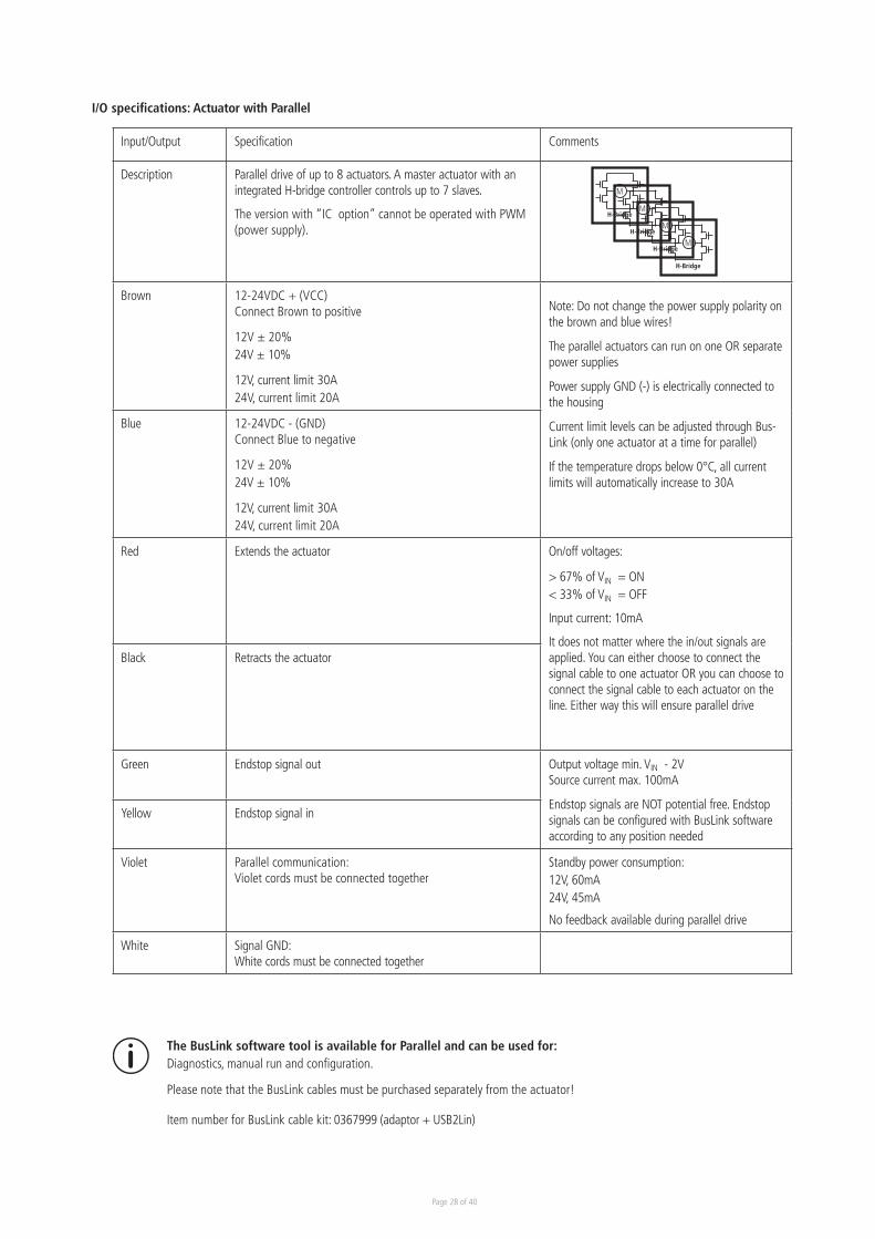
I/O specifications: Actuator with Parallel
Input/Output Specification Comments
Description Parallel drive of up to 8 actuators. A master actuator with an integrated H-bridge controller controls up to 7 slaves.
The version with “IC option” cannot be operated with PWM (power supply).
Brown 12-24VDC + (VCC) Connect Brown to positive
12V ± 20%24V ± 10%
12V, current limit 30A24V, current limit 20A
Note: Do not change the power supply polarity on the brown and blue wires!
The parallel actuators can run on one OR separate power supplies
Power supply GND (-) is electrically connected to the housing
Current limit levels can be adjusted through Bus-Link (only one actuator at a time for parallel)
If the temperature drops below 0°C, all current limits will automatically increase to 30A
Blue 12-24VDC - (GND) Connect Blue to negative
12V ± 20%24V ± 10%
12V, current limit 30A24V, current limit 20A
Red Extends the actuator On/off voltages:
> 67% of VIN = ON< 33% of VIN = OFF
Input current: 10mA
It does not matter where the in/out signals are applied. You can either choose to connect the signal cable to one actuator OR you can choose to connect the signal cable to each actuator on the line. Either way this will ensure parallel drive
Black Retracts the actuator
Green Endstop signal out Output voltage min. VIN - 2VSource current max. 100mA
Endstop signals are NOT potential free. Endstop signals can be configured with BusLink software according to any position needed
Yellow Endstop signal in
Violet Parallel communication: Violet cords must be connected together
Standby power consumption: 12V, 60mA 24V, 45mA
No feedback available during parallel drive
White Signal GND: White cords must be connected together
M
H-BridgeM
H-BridgeM
H-BridgeM
H-Bridge
The BusLink software tool is available for Parallel and can be used for: Diagnostics, manual run and configuration.
Please note that the BusLink cables must be purchased separately from the actuator!
Item number for BusLink cable kit: 0367999 (adaptor + USB2Lin)
Page 29 of 40
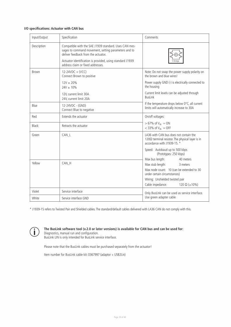
I/O specifications: Actuator with CAN bus
Input/Output Specification Comments
Description Compatible with the SAE J1939 standard. Uses CAN mes-sages to command movement, setting parameters and to deliver feedback from the actuator.
Actuator identification is provided, using standard J1939 address claim or fixed addresses.
Brown 12-24VDC + (VCC) Connect Brown to positive
12V ± 20%24V ± 10%
12V, current limit 30A24V, current limit 20A
Note: Do not swap the power supply polarity on the brown and blue wires!
Power supply GND (-) is electrically connected to the housing
Current limit levels can be adjusted through BusLink
If the temperature drops below 0°C, all current limits will automatically increase to 30A
Blue 12-24VDC - (GND) Connect Blue to negative
Red Extends the actuator On/off voltages:
> 67% of VIN = ON< 33% of VIN = OFF
Black Retracts the actuator
Green CAN_L LA36 with CAN bus does not contain the 120Ω terminal resistor. The physical layer is in accordance with J1939-15. *
Speed: Autobaud up to 500 kbps (Prototypes: 250 kbps)
Max bus length: 40 meters
Max stub length: 3 meters
Max node count: 10 (can be extended to 30 under certain circumstances)
Wiring: Unshielded twisted pair
Cable impedance: 120 Ω (±10%)
Yellow CAN_H
Violet Service interface Only BusLink can be used as service interface. Use green adapter cableWhite Service interface GND
M
H-Bridge
The BusLink software tool (v.2.0 or later versions) is available for CAN bus and can be used for: Diagnostics, manual run and configuration.BusLink LIN is only intended for BusLink service interface.
Please note that the BusLink cables must be purchased separately from the actuator!
Item number for BusLink cable kit: 0367997 (adaptor + USB2Lin)
* J1939-15 refers to Twisted Pair and Shielded cables. The standard/default cables delivered with LA36 CAN do not comply with this.
Page 30 of 40
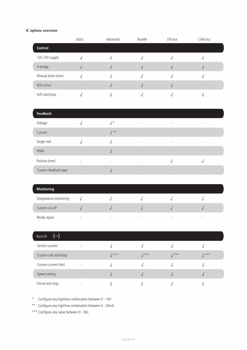
Control
12V, 24V supply √ √ √ √ √
Basic Advanced Parallel LIN bus CAN bus
H-bridge √ √ √ √ √
Manual drive in/out √ √ √ √ √
EOS in/out - √ √ √ -
Soft start/stop √ √ √ √ √
Feedback
Voltage √ √ * - - -
Current - √ ** - - -
Single Hall √ √ - - -
PWM - √ - - -
Position (mm) - - - √ √
Custom feedback type - √ - - -
Monitoring
Temperature monitoring √ √ √ √ √
Current cut-off √ √ √ √ √
Ready signal - - - - -
BusLink
Service counter - √ √ √ √
Custom soft start/stop - √ *** √ *** √ *** √ ***
Custom current limit - √ √ √ √
Speed setting - √ √ √ √
Virtual end stop - √ √ √ √
* Configure any high/low combination between 0 - 10V
*** Configure any value between 0 - 30s
** Configure any high/low combination between 4 - 20mA
IC options overview
Page 31 of 40
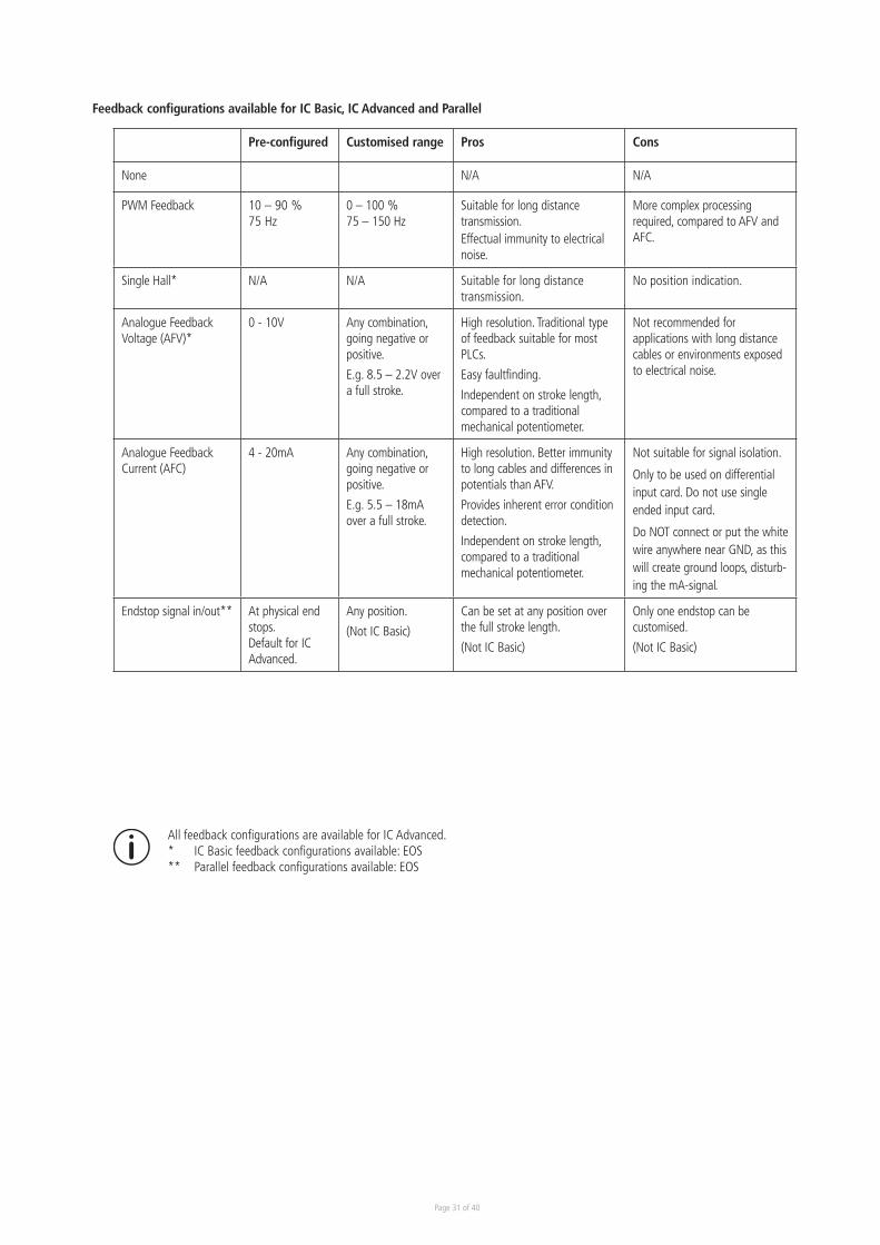
Feedback configurations available for IC Basic, IC Advanced and Parallel
Pre-configured Customised range Pros Cons
None N/A N/A
PWM Feedback 10 – 90 % 75 Hz
0 – 100 %75 – 150 Hz
Suitable for long distance transmission.Effectual immunity to electrical noise.
More complex processing required, compared to AFV and AFC.
Single Hall* N/A N/A Suitable for long distance transmission.
No position indication.
Analogue FeedbackVoltage (AFV)*
0 - 10V Any combination, going negative or positive.
E.g. 8.5 – 2.2V over a full stroke.
High resolution. Traditional type of feedback suitable for most PLCs.
Easy faultfinding.
Independent on stroke length, compared to a traditional mechanical potentiometer.
Not recommended for applications with long distance cables or environments exposed to electrical noise.
Analogue FeedbackCurrent (AFC)
4 - 20mA Any combination, going negative or positive.
E.g. 5.5 – 18mA over a full stroke.
High resolution. Better immunity to long cables and differences in potentials than AFV.
Provides inherent error condition detection.
Independent on stroke length, compared to a traditional mechanical potentiometer.
Not suitable for signal isolation.
Only to be used on differential input card. Do not use single ended input card.
Do NOT connect or put the white wire anywhere near GND, as this will create ground loops, disturb-ing the mA-signal.
Endstop signal in/out** At physical end stops.Default for IC Advanced.
Any position.
(Not IC Basic)
Can be set at any position over the full stroke length.
(Not IC Basic)
Only one endstop can be customised.
(Not IC Basic)
All feedback configurations are available for IC Advanced.* IC Basic feedback configurations available: EOS** Parallel feedback configurations available: EOS
Page 32 of 40
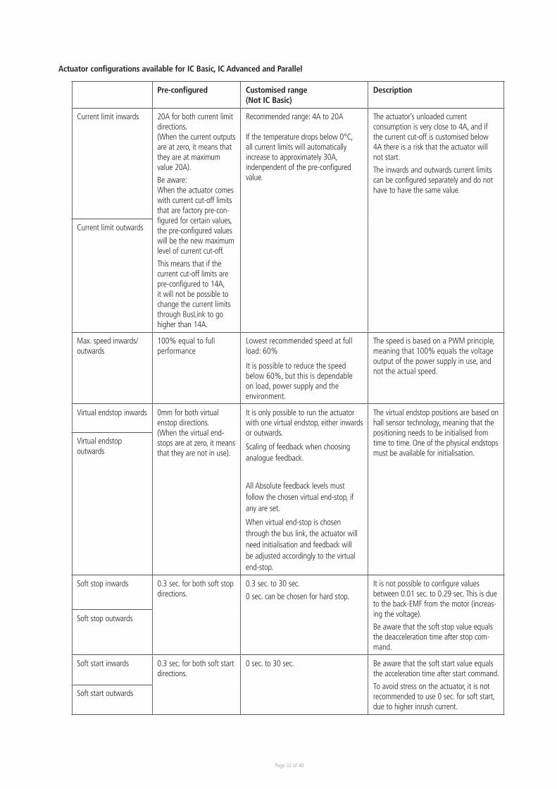
Actuator configurations available for IC Basic, IC Advanced and Parallel
Pre-configured Customised range(Not IC Basic)
Description
Current limit inwards 20A for both current limit directions.(When the current outputs are at zero, it means that they are at maximum value 20A).
Be aware:When the actuator comes with current cut-off limits that are factory pre-con-figured for certain values, the pre-configured values will be the new maximum level of current cut-off.
This means that if the current cut-off limits are pre-configured to 14A, it will not be possible to change the current limits through BusLink to go higher than 14A.
Recommended range: 4A to 20A
If the temperature drops below 0°C, all current limits will automatically increase to approximately 30A, indenpendent of the pre-configured value.
The actuator’s unloaded current consumption is very close to 4A, and if the current cut-off is customised below 4A there is a risk that the actuator will not start.
The inwards and outwards current limits can be configured separately and do not have to have the same value.
Current limit outwards
Max. speed inwards/outwards
100% equal to full performance
Lowest recommended speed at full load: 60%
It is possible to reduce the speed below 60%, but this is dependable on load, power supply and the environment.
The speed is based on a PWM principle, meaning that 100% equals the voltage output of the power supply in use, and not the actual speed.
Virtual endstop inwards 0mm for both virtual enstop directions.(When the virtual end-stops are at zero, it means that they are not in use).
It is only possible to run the actuator with one virtual endstop, either inwards or outwards.
Scaling of feedback when choosing analogue feedback.
All Absolute feedback levels must follow the chosen virtual end-stop, if any are set.
When virtual end-stop is chosen through the bus link, the actuator will need initialisation and feedback will be adjusted accordingly to the virtual end-stop.
The virtual endstop positions are based on hall sensor technology, meaning that the positioning needs to be initialised from time to time. One of the physical endstops must be available for initialisation.
Virtual endstop outwards
Soft stop inwards 0.3 sec. for both soft stop directions.
0.3 sec. to 30 sec.
0 sec. can be chosen for hard stop.
It is not possible to configure values between 0.01 sec. to 0.29 sec. This is due to the back-EMF from the motor (increas-ing the voltage).
Be aware that the soft stop value equals the deacceleration time after stop com-mand.
Soft stop outwards
Soft start inwards 0.3 sec. for both soft start directions.
0 sec. to 30 sec. Be aware that the soft start value equals the acceleration time after start command.
To avoid stress on the actuator, it is not recommended to use 0 sec. for soft start, due to higher inrush current.
Soft start outwards
Page 33 of 40
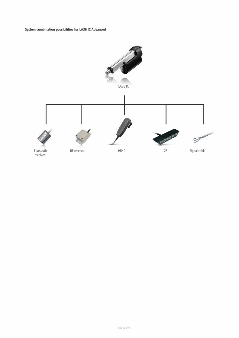
System combination possibilities for LA36 IC Advanced
LA36 IC
Bluetooth receiver
RF receiver HB40 DP Signal cable
Page 34 of 40
Chapter 3
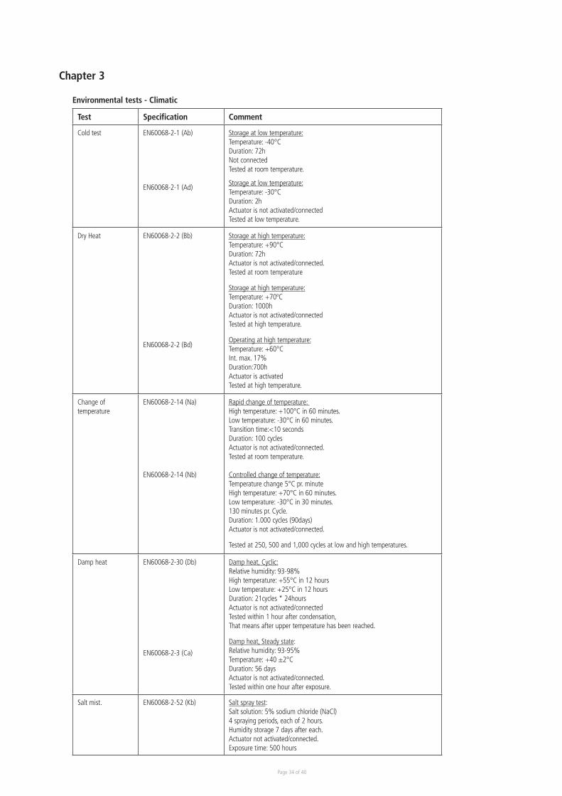
Environmental tests - Climatic
Test Specification Comment
Cold test EN60068-2-1 (Ab)
EN60068-2-1 (Ad)
Storage at low temperature:Temperature: -40°CDuration: 72hNot connectedTested at room temperature.
Storage at low temperature:Temperature: -30°CDuration: 2hActuator is not activated/connectedTested at low temperature.
Dry Heat EN60068-2-2 (Bb)
EN60068-2-2 (Bd)
Storage at high temperature:Temperature: +90°CDuration: 72hActuator is not activated/connected.Tested at room temperature
Storage at high temperature:Temperature: +70ºCDuration: 1000hActuator is not activated/connectedTested at high temperature.
Operating at high temperature:Temperature: +60°CInt. max. 17%Duration:700hActuator is activatedTested at high temperature.
Change of temperature
EN60068-2-14 (Na)
EN60068-2-14 (Nb)
Rapid change of temperature: High temperature: +100°C in 60 minutes.Low temperature: -30°C in 60 minutes.Transition time:<10 secondsDuration: 100 cyclesActuator is not activated/connected.Tested at room temperature.
Controlled change of temperature:Temperature change 5°C pr. minuteHigh temperature: +70°C in 60 minutes.Low temperature: -30°C in 30 minutes.130 minutes pr. Cycle. Duration: 1.000 cycles (90days)Actuator is not activated/connected.
Tested at 250, 500 and 1,000 cycles at low and high temperatures.
Damp heat EN60068-2-30 (Db)
EN60068-2-3 (Ca)
Damp heat, Cyclic:Relative humidity: 93-98%High temperature: +55°C in 12 hours Low temperature: +25°C in 12 hoursDuration: 21cycles * 24hoursActuator is not activated/connectedTested within 1 hour after condensation,That means after upper temperature has been reached.
Damp heat, Steady state:Relative humidity: 93-95%Temperature: +40 ±2°CDuration: 56 daysActuator is not activated/connected.Tested within one hour after exposure.
Salt mist. EN60068-2-52 (Kb) Salt spray test: Salt solution: 5% sodium chloride (NaCl)4 spraying periods, each of 2 hours.Humidity storage 7 days after each.Actuator not activated/connected.Exposure time: 500 hours
Page 35 of 40
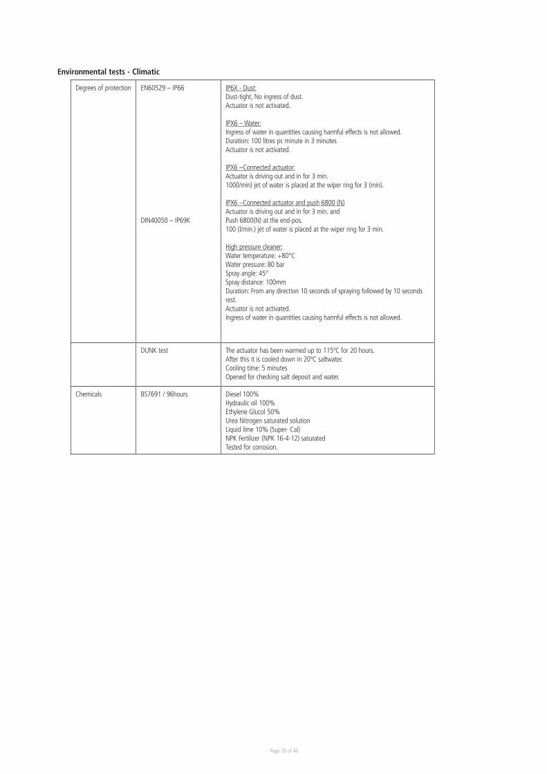
Degrees of protection EN60529 – IP66
DIN40050 – IP69K
IP6X - Dust:Dust-tight, No ingress of dust.Actuator is not activated.
IPX6 – Water:Ingress of water in quantities causing harmful effects is not allowed.Duration: 100 litres pr. minute in 3 minutesActuator is not activated.
IPX6 –Connected actuator:Actuator is driving out and in for 3 min. 100(l/min) jet of water is placed at the wiper ring for 3 (min).
IPX6 –Connected actuator and push 6800 (N)Actuator is driving out and in for 3 min. andPush 6800(N) at the end-pos.100 (l/min.) jet of water is placed at the wiper ring for 3 min.
High pressure cleaner:Water temperature: +80°CWater pressure: 80 barSpray angle: 45°Spray distance: 100mmDuration: From any direction 10 seconds of spraying followed by 10 seconds rest.Actuator is not activated.Ingress of water in quantities causing harmful effects is not allowed.
DUNK test The actuator has been warmed up to 115ºC for 20 hours.After this it is cooled down in 20ºC saltwater. Cooling time: 5 minutesOpened for checking salt deposit and water.
Chemicals BS7691 / 96hours Diesel 100%Hydraulic oil 100%Ethylene Glucol 50%Urea Nitrogen saturated solutionLiquid lime 10% (Super- Cal)NPK Fertilizer (NPK 16-4-12) saturatedTested for corrosion.
Environmental tests - Climatic
Page 36 of 40
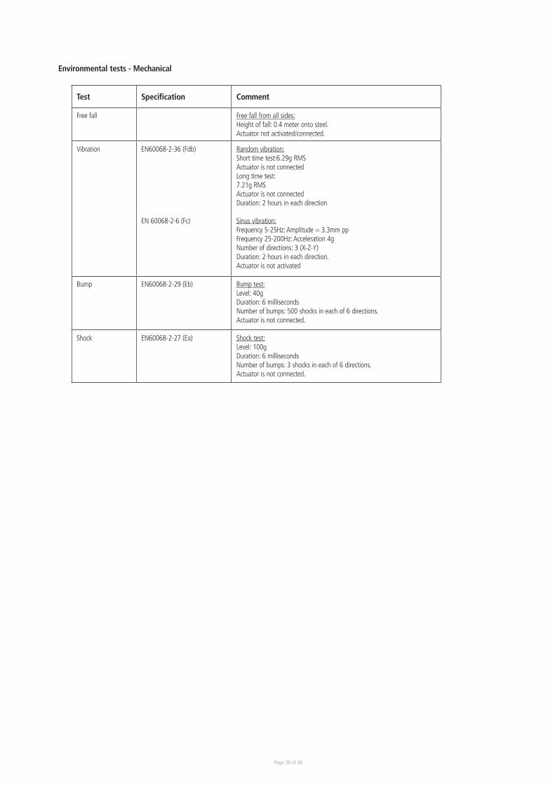
Test Specification Comment
Free fall Free fall from all sides:Height of fall: 0.4 meter onto steel.Actuator not activated/connected.
Vibration EN60068-2-36 (Fdb)
EN 60068-2-6 (Fc)
Random vibration: Short time test:6.29g RMSActuator is not connectedLong time test:7.21g RMSActuator is not connectedDuration: 2 hours in each direction
Sinus vibration:Frequency 5-25Hz: Amplitude = 3.3mm ppFrequency 25-200Hz: Acceleration 4gNumber of directions: 3 (X-Z-Y)Duration: 2 hours in each direction.Actuator is not activated
Bump EN60068-2-29 (Eb) Bump test:Level: 40gDuration: 6 millisecondsNumber of bumps: 500 shocks in each of 6 directions.Actuator is not connected.
Shock EN60068-2-27 (Ea) Shock test:Level: 100gDuration: 6 millisecondsNumber of bumps: 3 shocks in each of 6 directions.Actuator is not connected.
Environmental tests - Mechanical
Page 37 of 40
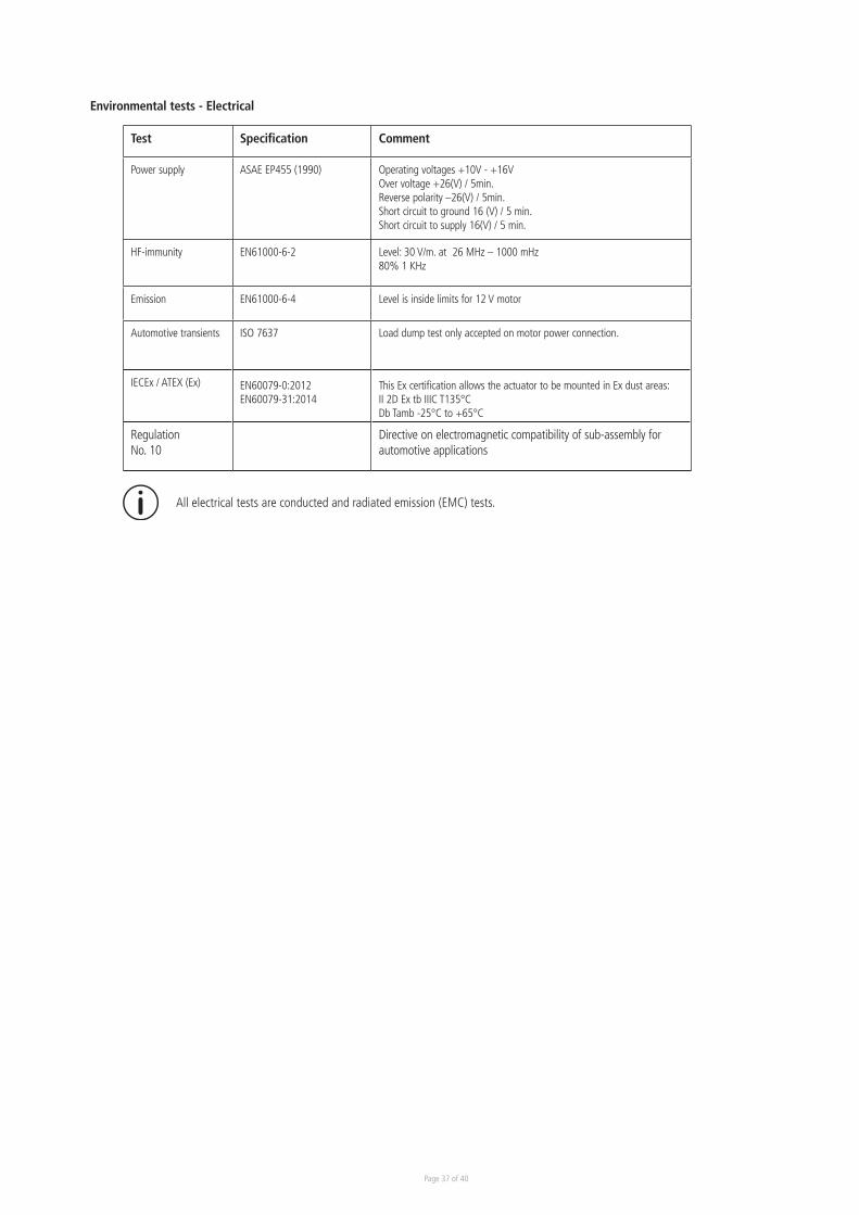
Environmental tests - Electrical
Test Specification Comment
Power supply ASAE EP455 (1990) Operating voltages +10V - +16VOver voltage +26(V) / 5min.Reverse polarity –26(V) / 5min.Short circuit to ground 16 (V) / 5 min.Short circuit to supply 16(V) / 5 min.
HF-immunity EN61000-6-2 Level: 30 V/m. at 26 MHz – 1000 mHz80% 1 KHz
Emission EN61000-6-4 Level is inside limits for 12 V motor
Automotive transients ISO 7637 Load dump test only accepted on motor power connection.
IECEx / ATEX (Ex) EN60079-0:2012EN60079-31:2014
This Ex certification allows the actuator to be mounted in Ex dust areas:II 2D Ex tb IIIC T135°C Db Tamb -25°C to +65°C
Regulation No. 10
Directive on electromagnetic compatibility of sub-assembly for automotive applications
All electrical tests are conducted and radiated emission (EMC) tests.

Page 38 of 40

Page 39 of 40

Copy
right
© L
INAK
201
8.07
. M
A M
9-02
-148
-AC
. Cha
pter
5.1
2
Terms of useThe user is responsible for determining the suitability of LINAK products for specific application. LINAK takes great care in providing accurate and up-to-date information on its products. However, due to continuous development in order to improve its products, LINAK products are subject to frequent modifications and changes without prior notice. Therefore, LINAK cannot guarantee the correct and actual status of said information on its products. While LINAK uses its best efforts to fulfil orders, LINAK cannot, for the same reasons as mentioned above, guarantee the availability of any particular product. Therefore, LINAK reserves the right to discontinue the sale of any product displayed on its website or listed in its catalogues or other written material drawn up by LINAK.All sales are subject to the Standard Terms of Sale and Delivery for LINAK. For a copy hereof, please contact LINAK.
F O R M O U N T I N G I N S T R U C T I O N S A N D G U I D A N C E I N U S A G E , P L E A S E S E E T H E R E L E V A N T U S E R ’ S M A N U A L S