Embed Size (px)
Citation preview

Keep this manual nearby for future reference.
MODEL:BE10
Side mounted motor axis
S E R I E S
ACTUATOR INSTRUCTION MANUAL ACTUATOR INSTRUCTION MANUAL

Introduction
Before using the ROIBOT BA–III series, read through and completely understand this instruction manual to assure
correct use.
For general information for the ROIBOT Arm BAIII Series, refer to CA25 Instruction Manual (Basic Part).
CAUTION
1. The contents of this manual are subject to change without prior notice.
2. The contents of this manual are subject to change without prior notice to effect improvements.
3. All efforts have been made to assure the contents of this manual. If you have any questions, or find any
mistakes, however, please contact Toshiba Machine.
4. Toshiba Machine will not be held responsible for any effects caused by using this equipment, regardless of Item
3 above.
5. This equipment does not have an explosion-proof structure. Take utmost care of the operating environment.
Contents Chapter 1 Safety ........................................................................................................................................................... 1 ■1.1 Cautions for safety ........................................................................................................................................... 1 ■1.2 For your safe operation .................................................................................................................................... 5 ■1.3 Warranty .......................................................................................................................................................... 8
Chapter 2 Shipment List............................................................................................................................................. 10 ■2.1 Shipment list .................................................................................................................................................. 10
Chapter 3 Axis Specifications ................................................................................................................................... 11 ■3.1 Axis type and names of individual parts ........................................................................................................ 11 ■3.2 Single axis specification ................................................................................................................................ 12
Chapter 4 Installing Actuator (Axis) .......................................................................................................................... 16 ■4.1 Installing Actuator (Axis) .............................................................................................................................. 17 ■4.2 Robot type for each Axis ................................................................................................................................ 17 ■4.3 Parameter values ............................................................................................................................................ 18
Chapter 5 Maintenance .............................................................................................................................................. 20 ■5.1 Precautions for inspection and maintenance work ........................................................................................... 20 ■5.2 Inspection before starting the work ................................................................................................................ 21 ■5.3 Periodic inspection ......................................................................................................................................... 21 ■5.4 Greasing ......................................................................................................................................................... 22 ■5.5 Cleaning ......................................................................................................................................................... 23 ■5.6 Motor and belt replacement procedure ........................................................................................................... 23 ■5.7 Changing side mounted motor direction ........................................................................................................ 26 ■5.8 Origin position adjustment ............................................................................................................................. 27 ■5.9 Replacement of ball screw ............................................................................................................................. 28 ■5.10 Replacement of linear guide ........................................................................................................................ 28
Chapter 6 Spare Parts ................................................................................................................................................. 29 ■6.1 Maintenance ................................................................................................................................................... 29

1
Overview • This manual describes the axis type expression method, specifications and motor replacement procedures, etc.,
according to the type of axis.
• For the installation, see the instruction manual (installation of actuator) provided separately.
Chapter 1 Safety
■1.1 Cautions for safety
● Before the installation, programming, operation, maintenance and inspection of the equipment, be sure to
read through this manual so that you can use the ROIBOT with safety.
● After you have read this manual, keep it nearby for future reference.
This manual contain the important information to prevent injury to the operators and persons nearby, to prevent
damage to assets and to assure correct use of the equipment.
Make sure that you have well understood the following details (indications and symbols) before reading this manual.
Always observe the information that is noted.
: If you have neglected this instruction and caused a handling error, death or serious injury
may occur.
: If you have neglected this instruction and caused a handling error, human injury or
property damage (damages to houses, household goods and domestic animals) may
occur.
: This gives a brief description of the major points of operation procedures, precautions
and method for effective use of the machine.
Be sure to observe the instructions for ensuring
operation safety of the ROIBOT.
CAUTION
WARNING
CAUTION

2
WARNING
• Install the safety fences to prevent anyone from entering the working envelope of the robot.
When the door is attached to the safety fence, the robot should be stopped at emergency at the same time that the door has opened.
• Connect the EMERGENCY STOP pushbutton switch to the emergency stop input terminal of the controller and mount the same switch at an easy-to-operate place in an emergency.
The EMEGENCY STOP switch must not be reset automatically and cannot be reset negligently by any person.
• Wiring should be done safely and completely according to the Electrical Installations Technical Requirements and Interior Wiring Requirements of Japan.
Incorrect wiring will result in an electric shock or a fire.
• The equipment MUST NOT be repaired or modified without prior written permission from the manufacturer.
Otherwise, an accident or damage will be caused.
• Before the maintenance and inspection, be sure to turn off the controller main power switch. Take all necessary measures to prevent anyone other than the worker engaged in adjustment of the robot from negligently turning the power on. (Lock the switch and put a tag showing "DO NOT turn the power on.") Also, DO NOT touch the controller interior three (3) minutes after the power is turned off.
Otherwise, you may get an electric shock due to residual voltage of the capacitor.
• DO NOT touch the motor, heat sink and cement resistor in the controller.
They are too hot and you may get burnt. Before performing inspection, take enough time to cool them off.
• DO NOT pour water on the equipment interior or exterior, or drain water from it. Otherwise, you may get an electric shock, or the equipment will be damaged.
When the equipment has contaminated, wipe it off with a hard squeezed cloth. DO NOT use a thinner, benzine or other organic solvent.
• DO NOT throw away metals, combustibles or other contaminant into the opening of this equipment.
A fire or an electric shock will be caused.
• DO NOT put your finger or hand on the movable part or opening of the equipment.
Otherwise, you may get injured.
• When using the actuator in other than the horizontal state, be sure to select the actuator with brake.
Otherwise, the slider will drop at power OFF, and you will be injured.

3
WARNING
• As the equipment is heavy, make sure of its weight and gravity center position and disconnect the cables when carrying the equipment.
Also, DO NOT carry the equipment with the slider. Otherwise, the slider will move and you will get injured.
• DO NOT use this equipment for the living body as a massaging machine.
Otherwise, you will be injured due to incorrect teaching or mis-operation.
• This equipment has not a sealed structure. During use, grease of the ball screw or wear of the belt may scatter from the opening of the equipment.
When using this equipment for food and chemical applications, take appropriate measures against entry of them.
• Enter the robot type and initialize the memory correctly.
Otherwise, the robot may move unexpectedly and you will be injured.
• DO NOT use this equipment in an atmosphere of inflammable gas or an atmosphere inducing an explosion.
As this equipment is not explosion-proof, it may explode in the worst occasion.
• DO NOT damage, break, process, forcibly bend, stretch, place a heavy object on or pinch the cables (power cable, controller cable).
Otherwise, an electric shock or a fire will be caused.
• Should an abnormality such as smoke or nasty smell occur, turn the power off immediately and stop using the equipment.
If the equipment is used continuously, an electric shock or a fire will be caused.
When using the side mounted motor axis in the vertical condition, be sure to check for the belt on a regular basis. Replace the belt every 3,000-hour operation.
If the belt whose service life already ended is used continuously, it may be broken or the slider may
drop, and you will be injured.

4
CAUTION
• DO NOT place the equipment at a place where the ambient temperature exceeds 40°C, or where the temperature changes sharply, causing condensing, or where it is exposed to direct sunlight.
Additionally, if the equipment is installed at a narrow place, the ambient temperature rises due to heat generation in the controller itself or external device, which will result in malfunction or mis-operation of the equipment.
• DO NOT use the equipment at a place where an impact or vibration is involved. Also, DO NOT use the equipment in an atmosphere where conductive dust, corrosive gas or oil mist generates.
Otherwise, a fire, electric shock, malfunction or mis-operation will be caused.
• DO NOT use the equipment at a place where too much dust or dirt exists.
If the equipment is used at such a place, it may malfunction because this equipment is not dust-proof.
• DO NOT use repair parts other than those designated by the manufacturer.
Otherwise, the equipment cannot be operated to its full capacity and will cause malfunction.
• Mount the robot on a highly rigid frame.
If rigidity of the frame is not enough, vibration (or resonance) may be caused during the robot operation, adversely affecting the operation.
5
■1.2 For your safe operation
When you use the ROIBOT BE Series, be sure to take the measures in conformity to the following instruction:
This machine is an industrial robot in conformance to the provisions of Paragraph 31of Article 36 of the Ordinance on
Industrial Safety and Hygiene. Necessary cautions are specified in the "Selection", "Installation", "Use", "Periodic
Inspection, etc." and "Education" of the "Technical Guideline on Safety Standards for Use of Industrial Robot"
conforming to the Article 28 of the Industrial Safety and Health Law. You are requested to read them carefully and
to observe the instructions. The following introduces some of them.
■1.2.1 Safety measures
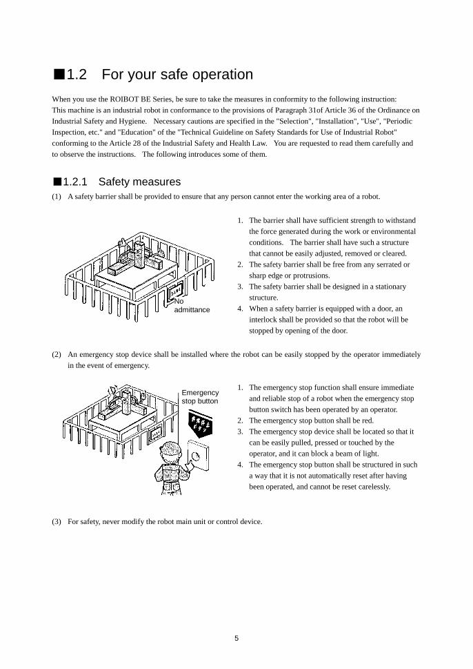
(1) A safety barrier shall be provided to ensure that any person cannot enter the working area of a robot.
1. The barrier shall have sufficient strength to withstand
the force generated during the work or environmental
conditions. The barrier shall have such a structure
that cannot be easily adjusted, removed or cleared.
2. The safety barrier shall be free from any serrated or
sharp edge or protrusions.
3. The safety barrier shall be designed in a stationary
structure.
4. When a safety barrier is equipped with a door, an
interlock shall be provided so that the robot will be
stopped by opening of the door.
(2) An emergency stop device shall be installed where the robot can be easily stopped by the operator immediately
in the event of emergency.
1. The emergency stop function shall ensure immediate
and reliable stop of a robot when the emergency stop
button switch has been operated by an operator.
2. The emergency stop button shall be red.
3. The emergency stop device shall be located so that it
can be easily pulled, pressed or touched by the
operator, and it can block a beam of light.
4. The emergency stop button shall be structured in such
a way that it is not automatically reset after having
been operated, and cannot be reset carelessly.
(3) For safety, never modify the robot main unit or control device.
No admittance
Emergency stop button

6
■1.2.2 Precautions for installation
Observe the following instructions when installing a robot:
(1) The robot shall be laid out to ensure the work space required for robot teaching, maintenance and inspection.
(2) The robot controller, other controllers and stationary operation panel shall be installed outside the movable range
and where the operator can watch the robot operations.
(3) The pressure gauge, hydraulic pressure gauge and other instruments shall be installed in clearly visible positions.
(4) The electric wiring and hydraulic/pneumatic piping shall be provided with protective covers if they may be
damaged.
(5) To ensure effective operation of the emergency stop device in the event of emergency, emergency stop device
switches shall be installed on locations other than the operation panel, as required.
■1.2.3 Precautions for use
Observe the following instructions when using a robot:
[Work within the movable range]
(1) Work provisions
Determine provisions for the following items and perform the work in conformity to them:
1. Root operation methods and procedures required in the work such as startup method and switch handling
method.
2. Speed of robot main unit in teaching.
3. Signaling method for work adjustment among more than one operator.
4. Action to be taken by the operator for each problem.
5. Procedures for confirming the release of the emergency and safety when restarting the robot operation after
the robot operation has been stopped due to the operation of the emergency stop device.
6. Measures to protect against the hazard due to unexpected operation of the robot described below (in addition
to the above items), or the hazard caused by a robot operation error.
- Indication on the operation panel.
- Measures to ensure safety of the operator working within the movable range.
- Working position and posture.
- Prevention of operation error due to noise.
- Signaling method for work adjustment with operators of related devices.
- Error type and evaluation procedure.
7. The work provisions shall meet the requirements of the robot type, installation site and work.
8. The work provisions shall be prepared by consultation with the related operators, manufacturer's engineers
and industrial safety consultant.
(2) Indication on the operation panel
To ensure that the start switch and selector switch will not be carelessly operated by a person other than the
personnel in charge of this work, the switch shall be provided with an easy-to-read indication to show that the
work is in progress. Alternatively, the operation panel cover shall be provided with locking or other means.
(3) Measures to ensure the operation safety of the personnel working within the movable range
Any one of the following measures or other measures on the equal or higher level shall be taken so that you can
stop the robot operation immediately in the event of an error when working within the movable range:

7
1. An adequately authorized supervisor shall be assigned outside the movable range and where the robot
operations can be observed. This supervisor shall be exclusively in charge of the supervision and shall be
responsible for the following:
- The supervisor shall cause the emergency stop device to be operated immediately in the event of an error.
- The supervisor shall ensure that a person other than the personnel in charge of this work is kept outside the
movable range.
2. The emergency stop device switch shall be placed under the control of the person working within the
movable range.
3. A portable operation panel having a structure capable of on/off operation of the power source, oil hydraulic
or pneumatic source shall be used in the work.
(4) Inspection prior to start of the work such as teaching
Prior to start of the work such as teaching, the following items shall be inspected. If any error is detected,
immediately repair the trouble or take other required action.
1. Check if the covering or sheathing of the external power source is damaged or not. (This check must be
made after the power has been turned off).
2. Check if the operation of the robot proper is faulty.
3. Check for the functions of the braking device and emergency stop device.
4. Check if there is any leakage of air or oil from the piping.
(5) Cleaning of working tools
When such working tools as a painting nozzle are mounted on the robot proper, and these working tools must be
cleaned, it is preferred that these tools should be automatically cleaned so that the number of machines entering
the movable range can be minimized.
(6) Release of residual pressure
Before disassembling the pneumatic components or replacing their parts, release the residual pressure in the
drive cylinder.
(7) Operation check
Perform the verification operation without entering the movable range, wherever possible.
(8) Illuminance
The illuminance required for operation safety shall be maintained.
[For automatic operation]
(1) Action before startup
Before starting the robot, check for the following items in advance and determine a signaling method for work
adjustment among related operators.
1. Make sure that there is no person within the movable range.
2. The movable operation panel and tools shall be located at specified positions.
3. There shall be no error indication for the robot or related devices.
(2) Action for automatic operation and in the event of an error
1. Make sure that there is an indication to show that the automatic operation is now in progress, after the robot
has been started.
2. When a problem has occurred to the robot or related device and you have to enter the movable range to take
emergency measures, stop the robot operation, for example, by operating the emergency stop device before
entering the movable range. At the same time, carry a safety plug with you, and ensure that the start switch
is provided with the indication to show that the work is now in progress. Take measures so that any other
person than the operator in charge of the emergency measures cannot operate the robot.

8
Warning label for actuator
Part number: 55620157
WARNING
• Before the installation, programming, operation, maintenance and inspection of the equipment, be sure to read through this manual so that you can use the ROIBOT with safety.
• Install the safety fences to prevent anyone from entering the working envelope of the robot.
• DO NOT put your finger or hand on the movable part or opening of the equipment. Otherwise, you may get injured.
• When using the actuator in other than the horizontal state, be sure to select the actuator with brake. Otherwise, the slider will drop at power OFF, and you will be injured.
■1.3 Warranty
■1.3.1 Warranty period
This product is warranted for one of the following periods whichever comes first.
(1) For 24 months after shipment from our factory.
(2) For 18 months after installation at the customer's factory.
(3) For 4000 hours of operation.
■1.3.2 Details of warranty
(1) This product is warranted. The scope of the warrant includes the specifications and functions described in the
Specification, catalog and Instruction Manual. We are not responsible for any secondary or incidental damages
caused by the trouble of this product.
(2) We will repair, on a free-of-charge basis, the trouble caused in the handling or use of the product within the
warranty period of this product as described in the Instruction Manual attached to this product. Alternatively,
such trouble will be repaired after the product has been returned to our factory. If the problem is solved by a
dispatch of service personnel to meet the convenience of the customer, we may claim payment from your
company regarding the transportation expenses, lodging expenses or other expenditures not directly related to
the repair of the product.
For the safety instructions which seem especially important, relevant warning label is attached to the equipment.
When the label attached to the equipment has peeled off or the characters are defaced and unreadable, please procure it from our sales agent in your territory by specifying the part number, and attach it to the original place.
Requesting your cooperation

9
■1.3.3 Exemption from responsibility
The following cases shall be excluded from the scope of warrant.
(1) The trouble and damage caused by the use of the product according to a method not described in the Instruction
Manual, or by a careless error in use.
(2) Problems caused by chronological changes or wear by use (such as natural fading of paints, deterioration of the
consumable parts *1
).
(3) Problems caused by sensory phenomena (e.g. generated noise without affecting the function).
(4) Modification or disassembling not authorized by our company.
(5) Troubles or damages caused by inadequate maintenance and inspection or improper repair.
(6) Troubles or damages caused by natural disaster, fire and other external factors.
(7) Internal data such as programs and points created or modified by the customer.
(8) Problems caused when this product purchased in Japan is brought to an overseas country.
*1: Consumable parts are defined as the parts maintenance replacement parts (spare parts) described in the
Instruction Manual of each product, and the parts (e.g. backup battery) that must be replaced on a periodic basis.
■1.3.4 Precautions
(1) When you have used the product beyond the specifications of the product, we cannot warrant the basic
performances of the product.
(2) Should you fail to observe the instructions given in "WARNING" and "CAUTION" described in the Instruction
Manual, we are not responsible for any personal injury, damages or trouble that may occur.
(3) Please note that the "WARNING" and "CAUTION" described in the Instruction Manual, and other descriptions
are within the scope assumed by our company.
(4) The numerical values given as technical data are theoretical values as a guideline showing the durability and
others. They shall not be construed as indicating warranty. Note that these values are subject to change
according to the conditions of use.

10
Chapter 2 Shipment List
■2.1 Shipment list When the axis proper is shipped, it is composed of the following parts:
(1) Actuator(axis)
(2) Number of oval bolts attached (M6×30)
The above-mentioned axs-1 will be provided with the bolts in the number shown in the right-hand Table.
(3) Actuator Instruction Manual (this Manual)
Axis stroke (mm) Attached quantity
100~200 12
250~600 16
650~1000 20
1050~1250 26

11
Chapter 3 Axis Specifications
■3.1 Axis type and names of individual parts
■Type of axis
The following shows the axis type:
BE10E-UR-M20N-40
■ Names of individual parts
Axis stroke
10 100 mm
15 150 mm
20 200 mm
: :
A0 1000 mm
A5 1050 mm
: :
C0 1200 mm
C5 1250 mm
Series name
Frame No. 10 Size S
Type of motor
E 100 W Absolute
Slider type
S Short slider
M Medium slider
Ball screw lead 20 20 mm
10 10 mm
05 5 mm
Brake
N Without brake
B With brake
Motor set direction
UR Right side mounted axis
UL Left side mounted axis
UU Right side mounted axis
Motor cover
End block
Slider
Belt cover
Frame
Frame cover

12
■3.2 Single axis specification
■ Specifications
Type of axis BE10-U--
Motor AC 100-watt servo motor absolute
Drive method Ball screw 15 Lead 20 mm
Lead 10 mm Lead 5 mm
Guide method Linear guide (Single rail)
Medium slider bearing block ... 2 pieces
Short slider bearing block ... 1 piece
Maximum payload
mass (Note 1) Ball screw lead Horizontal
Vertical
- Regeneration
unit used
20 mm 20 kg 3 kg 5 kg
10 mm 40 kg 8 kg 12 kg
5 mm 80 kg 15 kg 22 kg
Maximum speed
(Note 2)
Ball screw lead 20 mm 1200 mm/s
Ball screw lead 10 mm 600 mm/s
Ball screw lead 5 mm 300 mm/s
Static permissible
moment (Note 3)
Medium slider MR:59 Nm MP:59 Nm MY:54 Nm
Short slider MR:49 Nm MP:14 Nm MY:13 Nm
Repeated positioning accuracy ±0.01 mm
Resolution 0.01 mm
Rated thrust Ball screw lead 20 mm 100 N
Ball screw lead 10 mm 200 N
Ball screw lead 5 mm 400 N
(Note 1) This indicates the value when the acceleration/deceleration time is 0.36 s or more.
(Note 2) The maximum speed will be as follows, depending on the axis stroke.
Stroke range Maximum speed
Lead 20 mm Lead 10 mm Lead 5 mm
650 mm or less 1200 mm/s 600 mm/s 300 mm/s
700~750 mm 1000 mm/s 500 mm/s 250 mm/s
800~850 mm 800 mm/s 400 mm/s 200 mm/s
900~1050 mm 600 mm/s 300 mm/s 150 mm/s
1100~1250 mm 400 mm/s 200 mm/s
(Note 3)
MR: Rolling Moment
MP: Pitching Moment
MY: Yawing Moment
MP
MY
MR
13
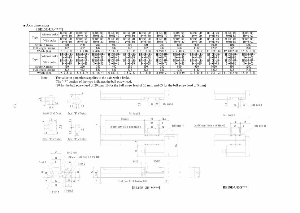
■ Axis dimensions
[BE10E-UR-****]
Note: The value in parenthesis applies to the axis with a brake.
The "**" portion of the type indicates the ball screw lead.
(20 for the ball screw lead of 20 mm, 10 for the ball screw lead of 10 mm, and 05 for the ball screw lead of 5 mm)
Type Without brake
BE10E-UR- M**N-10
BE10E-UR- M**N-20
BE10E-UR- M**N-30
BE10E-UR- M**N-40
BE10E-UR- M**N-50
BE10E-UR- M**N-60
BE10E-UR- M**N-70
BE10E-UR- M**N-80
BE10E-UR- M**N-90
BE10E-UR- M**N-A0
BE10E-UR- M**N-B0
BE10E-UR- M**N-C0
With brake BE10E-UR- M**B-10
BE10E-UR- M**B-20
BE10E-UR- M**B-30
BE10E-UR- M**B-40
BE10E-UR- M**B-50
BE10E-UR- M**B-60
BE10E-UR- M**B-70
BE10E-UR- M**B-80
BE10E-UR- M**B-90
BE10E-UR- M**B-A0
BE10E-UR- M**B-B0
BE10E-UR- M**B-C0
Stroke X (mm) 100 200 300 400 500 600 700 800 900 1000 1100 1200 Full length L(mm) 332 432 532 632 732 832 932 1032 1132 1232 1332 1432
Weight (kg) 5.0(5.3) 5.7(6.0) 6.4(6.7) 7.1(7.4) 7.8(8.1) 8.5(8.8) 9.2(9.5) 9.9(10.2) 10.6(10.9) 11.3(11.6) 12.0(12.3) 12.7(13.0)
Type Without brake
BE10E-UR- S**N-15
BE10E-UR- S**N-25
BE10E-UR- S**N-35
BE10E-UR- S**N-45
BE10E-UR- S**N-55
BE10E-UR- S**N-65
BE10E-UR- S**N-75
BE10E-UR- S**N-85
BE10E-UR- S**N-95
BE10E-UR- S**N-A5
BE10E-UR- S**N-B5
BE10E-UR- S**N-C5
With brake BE10E-UR- S**B-15
BE10E-UR- S**B-25
BE10E-UR- S**B-35
BE10E-UR- S**B-45
BE10E-UR- S**B-55
BE10E-UR- S**B-65
BE10E-UR- S**B-75
BE10E-UR- S**B-85
BE10E-UR- S**B-95
BE10E-UR- S**B-A5
BE10E-UR- S**B-B5
BE10E-UR- S**B-C5
Stroke X (mm) 150 250 350 450 550 650 750 850 950 1050 1150 1250 Full length L(mm) 332 432 532 632 732 832 932 1032 1132 1232 1332 1432
Weight (kg) 4.7(5.0) 5.4(5.7) 6.1(6.4) 6.8(7.1) 7.5(7.8) 8.2(8.5) 8.9(9.2) 9.6(9.9) 10.3(10.6) 11.0(11.3) 11.7(12.0) 12.4(12.7)
[BE10E-UR-M***] [BE10E-UR-S***]

14
[BE10E-UL-****]
Note: The value in parenthesis applies to the axis with a brake.
The "**" portion of the type indicates the ball screw lead. (20 for the ball screw lead of 20 mm, 10 for the ball screw lead of 10 mm, and 05 for the ball screw lead of 5 mm)
Type Without brake
BE10E-UL- M**N-20
BE10E-UL- M**N-30
BE10E-UL- M**N-40
BE10E-UL- M**N-50
BE10E-UL- M**N-60
BE10E-UL- M**N-70
BE10E-UL- M**N-80
BE10E-UL- M**N-90
BE10E-UL- M**N-A0
BE10E-UL- M**N-B0
BE10E-UR- M**N-C0
With brake BE10E-UL- M**B-20
BE10E-UL- M**B-30
BE10E-UL- M**B-40
BE10E-UL- M**B-50
BE10E-UL- M**B-60
BE10E-UL- M**B-70
BE10E-UL- M**B-80
BE10E-UL- M**B-90
BE10E-UL- M**B-A0
BE10E-UL- M**B-B0
BE10E-UR- M**B-C0
Stroke X (mm) 200 300 400 500 600 700 800 900 1000 1100 1200 Full length L(mm) 432 532 632 732 832 932 1032 1132 1232 1332 1432
Weight (kg) 5.7(6.0) 6.4(6.7) 7.1(7.4) 7.8(8.1) 8.5(8.8) 9.2(9.5) 9.9(10.2) 10.6(10.9) 11.3(11.6) 12.0(12.3) 12.7(13.0)
Type Without brake
BE10E-UL- S**N-25
BE10E-UL- S**N-35
BE10E-UL- S**N-45
BE10E-UL- S**N-55
BE10E-UL- S**N-65
BE10E-UL- S**N-75
BE10E-UL- S**N-85
BE10E-UL- S**N-95
BE10E-UL- S**N-A5
BE10E-UL- S**N-B5
BE10E-UR- S**N-C5
With brake BE10E-UL- S**B-25
BE10E-UL- S**B-35
BE10E-UL- S**B-45
BE10E-UL- S**B-55
BE10E-UL- S**B-65
BE10E-UL- S**B-75
BE10E-UL- S**B-85
BE10E-UL- S**B-95
BE10E-UL- S**B-A5
BE10E-UL- S**B-B5
BE10E-UR- S**B-C5
Stroke X (mm) 250 350 450 550 650 750 850 950 1050 1150 1250 Full length L(mm) 432 532 632 732 832 932 1032 1132 1232 1332 1432
Weight (kg) 5.4(5.7) 6.1(6.4) 6.8(7.1) 7.5(7.8) 8.2(8.5) 8.9(9.2) 9.6(9.9) 10.3(10.6) 11.0(11.3) 11.7(12.0) 12.4(12.7)
[BE10E-UL-M***] [BE10E-UL-S***]

15
[BE10E-UU-****]
Note: The value in parenthesis applies to the axis with a brake.
The "**" portion of the type indicates the ball screw lead. (20 for the ball screw lead of 20 mm, 10 for the ball screw lead of 10 mm, and 05 for the ball screw lead of 5 mm)
Type Without brake
BE10E-UU- M**N-10
BE10E-UU- M**N-20
BE10E-UU- M**N-30
BE10E-UU- M**N-40
BE10E-UU- M**N-50
BE10E-UU- M**N-60
BE10E-UU- M**N-70
BE10E-UU- M**N-80
BE10E-UU- M**N-90
BE10E-UU- M**N-A0
BE10E-UU- M**N-B0
BE10E-UU- M**N-C0
With brake BE10E-UU- M**B-10
BE10E-UU- M**B-20
BE10E-UU- M**B-30
BE10E-UU- M**B-40
BE10E-UU- M**B-50
BE10E-UU- M**B-60
BE10E-UU- M**B-70
BE10E-UU- M**B-80
BE10E-UU- M**B-90
BE10E-UU- M**B-A0
BE10E-UU- M**B-B0
BE10E-UU- M**B-C0
Stroke X (mm) 100 200 300 400 500 600 700 800 900 1000 1100 1200 Full length L(mm) 332 432 532 632 732 832 932 1032 1132 1232 1332 1432
Weight (kg) 5.0(5.3) 5.7(6.0) 6.4(6.7) 7.1(7.4) 7.8(8.1) 8.5(8.8) 9.2(9.5) 9.9(10.2) 10.6(10.9) 11.3(11.6) 12.0(12.3) 12.7(13.0)
Type Without brake
BE10E-UU- S**N-15
BE10E-UU- S**N-25
BE10E-UU- S**N-35
BE10E-UU- S**N-45
BE10E-UU- S**N-55
BE10E-UU- S**N-65
BE10E-UU- S**N-75
BE10E-UU- S**N-85
BE10E-UU- S**N-95
BE10E-UU- S**N-A5
BE10E-UU- S**N-B5
BE10E-UU- S**N-C5
With brake BE10E-UU- S**B-15
BE10E-UU- S**B-25
BE10E-UU- S**B-35
BE10E-UU- S**B-45
BE10E-UU- S**B-55
BE10E-UU- S**B-65
BE10E-UU- S**B-75
BE10E-UU- S**B-85
BE10E-UU- S**B-95
BE10E-UU- S**B-A5
BE10E-UU- S**B-B5
BE10E-UU- S**B-C5
Stroke X (mm) 150 250 350 450 550 650 750 850 950 1050 1150 1250 Full length L(mm) 332 432 532 632 732 832 932 1032 1132 1232 1332 1432
Weight (kg) 4.7(5.0) 5.4(5.7) 6.1(6.4) 6.8(7.1) 7.5(7.8) 8.2(8.5) 8.9(9.2) 9.6(9.9) 10.3(10.6) 11.0(11.3) 11.7(12.0) 12.4(12.7)
[BE10E-UU-M***] [BE10E-UU-S***]

16
Chapter 4 Installing Actuator (Axis)
This chapter describes the basic installation procedures for the axis and peripheral equipment.
Installation shall comply with the instructions of this Chapter. If the installation procedure is incorrect, robot
performance cannot be achieved. Not only that, the service life may be seriously reduced.
Precautions for installation
Environment of installation site
(1) The ambient environment for operation shall comply with the following requirements:
Ambient temperature Working temperature: 0C to 40C
Transportation and storage temperature: -10C to 50C
Relative humidity: 30 to 90%RH without dew condensation
Altitude: 1000 m or less
Vibration 0.98 m/s2 or less
Dust: Free from conductive dust or dirt
Gas: Free from flammable or corrosive gas
Magnetic field: Free from a nearby device that may generate magnetic field
Radiation: Not in the radiation controlled area
Others: Without greasy fume
(2) This product is not designed as an explosion proof structure. Do not use it in a dusty place. Further, take
sufficient care of the environment since it is not explosion-proof.
(3) Do not use it in a place with an organic solvent or white kerosene..
Of guide or ball screw grease is melted. It may cause malfunction.
Precautions in installation
(1) Do not allow the product to fall down or be collided with other object during the transportation.
(2) Install the product where maintenance and inspection are easier.
(3) Install the controller within the range where it can be reached from the robot proper by a standard cable.
(4) Installation
Install the product on a horizontal installation base.
The installation base shall have the length that allows only the frame portion to be mounted.
The installation base shall be made of a steel plate having a thickness of 9 mm or more where the plate has a
machined surface with flatness of 0.2 or less. Install this product on this base to correct the bend and twist of
the axis frame and to reinforce the axis frame.
Install the oval bolts (installation bolts) of the axis at a pitch of approximately 150 mm.
CAUTION

17
■4.1 Installing Actuator (Axis)
Installation shall comply with the following procedures:
(1) Setting the oval bolt
From the axis end face, insert the oval bolt in the T-groove of the frame installation surface.
(2) Mounting on the installation base
Drill installation holes on the installation base of the carriage at a pitch of approximately 150 mm, and mount the
product with oval bolts.
The T-grooves (for M4 nut) on the side and top of the frame are used to install the CN box
and optical parts. Never use these T-grooves to mount the axis.
The nut tightening torque shall be 5.3 N-m.
■4.2 Robot type for each Axis
The robot type is indicated by the 6-digit numerals specified for each robot type.
If this setting is made, various parameter values suited to the axis to be used can be automatically set. The input
procedure is given in Section 4.2 of the CA25 Instruction Manual (Basic Part).
When used as a slider traveling type axis (in normal use)
Lead (mm) Type of axis Robot type
BE10E
20 BE10E-U-20- 601030
10 BE10F- U-10- 601050
5 BE10F- U-05- 601070
●When you have used the origin change sensor (optional) and set the home position to the side
reverse to the normal side, input the robot type prior to change. After that, change the "Setting the
motor rotating direction" in paragraph 2 of Section 13.4.5 described in the CA25 Instruction
Manual (Basic Part) (Change it from 1 to 0).
CAUTION

18
■4.3 Parameter values
The parameters of this product are available in two types -- parameter 1 and parameter 2 -- depending on the
frequency of use. The relationship between each parameter and the robot type is illustrated below:
Setting the robot type allows the parameters on the circled portion on the left to be automatically changed.
■4.3.1 Values of parameter 1 for each robot type
This parameter has a higher frequency of use.
Side mounted motor axis (slider movable type)
Automatic
setting
Robot type
Parameter
601030 601050 601070
(Lead 20) (Lead 10) (Lead 5)
Software limit value (upper limit) 0000.00 0000.00 0000.00
Software limit value (lower limit) 0000.00 0000.00 0000.00
○ Servo gain
Position/Speed
Position 26 26 26
Speed 33 33 33
Pass area 200
Origin offset value 0000.00 0000.00 0000.00
Sequence of Return to Origin 1 (Note) 1 (Note) 1 (Note)
JOG speed L (Low speed) 010 010 010
H (High speed) 050 050 050
JOG inching movement 00.01 00.01 00.01
(Note) The Sequence of Return to Origin varies according to the combination format, installation conditions and
others. The customer is requested to set it in conformity to your operation conditions.
The initial value is common at "1" for all robot types. Thus, if there is no change, simultaneous origin
return of all axes can be achieved.

19
■4.3.2 Values of parameter 2 for each robot type
Side mounted motor axis (slider movable type)
Automatic
setting Robot type
Parameter
601030 601050 601070
(Lead 20) (Lead 10) (Lead 5)
Axis display X X X
In position data value 00.05 00.05 00.05
Overflow data value 20000 20000 20000
○ Feed forward data value 02000 02000 02000
○ Direction of motor rotation 0 0 0
○ Maximum speed 1200 600 300
○ Return to
origin speed
(L) Low speed 002.0 002.0 002.0
(M) Medium speed 020.0 020.0 020.0
(H) High speed 100.0 100.0 100.0
○ Return to origin method 0 0 0
○ Origin sensor logic 1 1 1
High speed return to origin position 0020.00 0020.00 0020.00
○ Lead 20.000 10.000 05.000
○ Encoder division number 32768 32768 32768
○ Encoder pulse multiplier 4 4 4
Encoder type (Note) a a a
Task and axis combination [1] [0] [0] [0]
Task order of priority [1] [1] [1] [1]
Task coordinate table 999 999 999 999
Task step number 5000 0000 0000 0000
(Note) The encoder type cannot be set in this robot type since setting for each axis is not available.
See Section 13.4.17 of the CA25 Instruction Manual (Basic Part).

20
Chapter 5 Maintenance
■5.1 Precautions for inspection and maintenance work
(1) Precautions for inspection and maintenance work
Observe the following instructions at the time of inspection and maintenance:
1. The robot shall be inspected and maintained by the personnel having a sufficient level of skill and experience.
If such personnel are not available, contact the manufacturer and request implementation of the relevant
work or education of the person in charge.
2. Use adequate illumination.
3. The start switch of the stationary operation panel or some other similar portion shall be provided with a
notice board to indicate that the inspection and maintenance work is currently in progress.
Before entering the fence and enclosure, lock the open power switch to turn off power completely. If the
access of the fence or enclosure is provided with a safety plug, be sure to carry the related plug with you.
4. If you have to enter the fence and enclosure for inspection and inspection of the control circuit, turn off the
drive power source.
5. If you have to operate the industrial robot in the inspection and maintenance work within the guard fence and
enclosure, you are recommended to take the following measures:
- Two persons should be engaged in the work in cooperation with each other. This means that role
assignment should be made in such a way that one person supervises the work of the other person during
the work.
- It is required to select such a speed that contact with the robot can be avoided in the event of a possible
operation error of the robot. Determine the speed suited for the relevant work.
- Take care of the robot operation during the work. Press the emergency stop button immediately when an
unexpected operation has been detected.
6. Before starting disassembly of the pressure gauge or replacement of the parts, release the residual pressure of
the cylinder.
7. Before starting disassembly of the hydraulic and pneumatic systems or replacement of parts, take a sufficient
care to avoid deposition or mixture of foreign substances such as dust.
(2) Action to be taken subsequent to inspection and maintenance work
1. After termination of the inspection or maintenance work, the inspection or maintenance worker shall carry
the tools back to the original position.
2. After termination of the maintenance work, be sure to perform a test run to verify the result. The test run
shall be performed from outside the fence and enclosure in principle.
3. After action of item 2 has been taken, the inspection or maintenance worker shall report termination of the
inspection or maintenance work to his superior.

21
■5.2 Inspection before starting the work
(1) Before starting your work with the robot, make sure of the following:
1. Brake device function
2. Emergency stop device function
3. Contact preventive equipment and robot interlock function
4. Related devices/robot interlocking function
5. Possible damage of the external wiring and piping
6. Error of supply voltage and hydraulic and pneumatic pressures
7. Operation error
8. Abnormal noise and vibration
9. Contact preventive equipment state
(2) This inspection shall be conducted outside the movable range wherever possible.
■5.3 Periodic inspection
Giving consideration to the robot installation site, frequency of use and durability of the parts, determine the
inspection standards including the inspection item, inspection procedure, evaluation criteria and implementation
period for the following items. Start inspection in conformity to these standards.
1. Looseness of major parts
2. Lubrication and other possible errors of the movable parts
3. Power transmission component trouble
4. Hydraulic and pneumatic system error
5. Electric system error
6. Operation failure detecting function error
7. Encoder error
8. Servo system error
■5.3.1 Timing belt inspection
Inspect the timing belt at intervals of approximately 500 hours.
Check the belt for deterioration, fatigue and scratches. Replace it if any problem has been detected. For
the replacement procedure, see the Instruction Manual for Shaft.
If you want to use the brake motor shuttling shaft in the vertical position (as a Z-axis), observe the following
instructions:
1. Be sure to replace the belt before operation for 3000 hours.
2. The service life of the belt heavily depends on the working environment and conditions. If any trouble
has been found out during the inspection, replace the belt immediately.
If the belt used in the vertical position is broken, a serious accident may occur.
Enforce belt replacement in good time.
CAUTION

22
■5.4 Greasing
(1) Greasing positions
The linear guide and ball screw of this product are provided with an oilless seal. To prevent a possible accident,
check for the greasing conditions and damages on a periodic basis. If insufficient lubrication has been found
out, supply grease according to the following steps. If any trouble such as a breakdown has been detected and
repair work is required, contact the Service Divisions shown at the end of this Manual, and request repair to be
made.
Greasing position Type of grease
(manufacturer)
Inspection and
greasing intervals Volume of grease
Ball screw
Albania Grease S2
(Shell) Every 6 months
A thin layer of grease applied on the
ball screw shaft
Linear guide A thin layer of grease applied on the
linear guide rail
Resin on slider Fill the groove.
(2) Inspection and greasing steps
1. Turn off the power and remove the power plug.
2. Remove the frame cover of the axis.
3. Inspect the linear guide and ball screw. If insufficient greasing has been found out, supply grease to the
above-mentioned greasing positions.
4. Slowly move the slider manually or in the jog mode (at a speed of about 50 mm per second or less) five or
more reciprocations and make sure that grease has been supplied into the ball nut and linear guide block.
5. Wipe off the overfilled or discolored grease.
6. Mount the frame cover again.
Linear guide
Ball screw
Resin on slider
Only the axis with a
stoke exceeding
600mm)

23
■5.5 Cleaning
Clean the robot proper.
Clean the robot proper in conformity to the following steps:
1. Turn off the power switch and remove the power plug.
2. Use waste cloth or such to remove the dust and dirt from the frame and covers etc.
3. Remove the frame cover and clean the dust and dirt from the frame cover. After removing it, supply grease
according to the greasing step
4. Mount the frame cover back.
■5.6 Motor and belt replacement procedure Replace the motor and belt according to the following steps.
(1) Remove the motor cover and belt cover and belt cover plate.
Turn OFF power before starting the work.
(2) Loosen the bolt on motor plate mounting screw.
Remove the belt from the axis.
(3) If the only belt exchange of implementation, please proceed to step (4).
Remove the motor, please attach a new motor in the same position.
(Mount it so that the motor lead wire will be located on the axis side.)
(4) Connect the axis and controller on a temporary basis. Please then connect the teaching pendant.
CAUTION
Belt cover
Motor cover
Motor cover plate
Belt cover plate
Motor plate
Motor prate mounting screw

24
(5) Connect the teaching pendant to the controller and return the axis to the origin.
Before starting the return to the origin, set the servo gains to "0" for both the position and
speed.
For the setting procedures, see Sections 13.3.3 and 13.3.4 of the CA25 Instruction Manual
(Basic Part).
Motor will rotate. Please do not touch absolutely pulley portion toothed.
(6) The motor rotates. Taking care not to touch the rotating part, move the slider close to the origin. If the
origin sensor has detected the slider, the motor starts the stop operation at the time of return to the origin
(7) After the motor has stopped (return to origin has been completed), move the slider so that the distance from
the motor block is 7 mm.
(8) Turn off the controller. And ball screw pulley, position of the motor pulley is, multiply the belt so as not to
shift. Please tighten the motor plate mounting screw while pulling the motor plate at about 59N (6kgf) then.
Before tightening the coupling fixing bolt, be sure to turn OFF the controller power.
(9) Turn ON the power again, and set the servo gain back to the original level. After that, make sure of the
return to origin.
(10) After that, turn OFF power and remove the controller cable.
CAUTION
CAUTION
Motor block Slider
CAUTION
Motor plate
Motor prate mounting screw
Pull
25
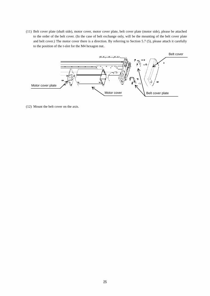
(11) Belt cover plate (shaft side), motor cover, motor cover plate, belt cover plate (motor side), please be attached
to the order of the belt cover. (In the case of belt exchange only, will be the mounting of the belt cover plate
and belt cover.) The motor cover there is a direction. By referring to Section 5.7 (5), please attach it carefully
to the position of the t-slot for the M4 hexagon nut..
(12) Mount the belt cover on the axis.
Belt cover
Motor cover
Motor cover plate
Belt cover plate

26
■5.7 Changing side mounted motor direction
Changing side mounted motor direction (left, right, bottom) If you want to change the, please change according to the
following figure.
In addition, parts of the motor mounting is common. Parts for motor mounting direction changes, does not need.
(1) Please remove the covers. (Section 5.6 (1) see)
(2) Please remove the belt. (Section 5.6 (2) see)
(3) Remove the motor plate mounting bolts, and mounting the motor plate in a predetermined folding direction,
please temporarily tighten the same bolt.
(4) Please temporarily connect the controller cable. Please adjust the origin. Then, please do the mounting of the
belt as well the "Section 5.6 (4)~(10)".
(5) Please attach the covers. (Section 5.6 (11) see)
Please note the direction of attaching the motor cover.
Note) Please note the motor cover mounting hole positions.
(Please so as not to damage the belt tightening the screws.)
BE10E-UR
BE10E-UU
E10E-UL
BE10E-UR/UL BE10E-UR/U
T-slot for M4 hexagon nut
Use the lower hole of the
three holes.
Use the center hole of the
three holes.

27
■5.8 Origin position adjustment
Adjust the origin according to the following procedure:
(1) When the origin sensor is ON (Note), slider positions shall have the following relationship at the origin.
Sensor installation
reference position
Origin sensor
ON position
Reference origin
position
Applicable axis A B C
BE10E-U-S10 (20) 33mm 12mm 7mm
BE10E-U-S05 31mm 10mm 7mm
BE10E-U-M10 (20) 58.5mm 12mm 7mm
BE10E-U-M05 56.5mm 10mm 7mm
(Note) A reed switch of B-contact specification is used as the origin sensor. Accordingly, the state is OFF in
electrical terms. In this Manual, however, this is represented as "ON" for the sake of easier
understanding.
The negative overrun position (-) indicates the position where the slider has hit the motor block damper
and cannot move toward the motor any further. Normally, the position about 5 mm shifted toward the
motor from the reference origin is the negative overrun position.
The origin sensor must be turned "ON" even if the slider is located at the negative overrun
position.
When the sensor has been turned OFF at the negative overrun position, the return to origin
will be disabled from this position.
(2) The origin is found in either one of two ends of the axis. It should be noted that, when the tip end of the axis is
assumed as the origin, the origin change sensor (optional) must be used.
If the origin must be changed close to the center of the stroke for the convenience of the customer, be sure to
provide a stopper at the overrun dimension of about 5 mm from the origin stop position.
The distance from the origin sensor ON position to the origin stop position should be set at 5 mm (for a ball
screw lead of 10 mm or 20 mm) and 3 mm (for a ball screw lead of 5 mm).
CAUTION
B
C
A
Slider
Motor block
Damper
Sensor (reed switch)
Belt Pulley Pulley
Sensor installation reference position

28
[Slide position checking procedure when origin sensor is turned ON]
Turn OFF the controller power, and move the slider 50 to 100 mm from the origin. After that, turn ON the
power and return the axis to the origin. (In case of the axis with a brake, turn ON the power. After that, use
the jog mode for this operation.)
The origin sensor ON position is where the slider speed changes (from intermediate to low speed) during
return to the origin.
In this case, the slider does not stop until the return to origin is completed (detection of Z phase). (It does not
stop at the origin sensor ON position.
When it must be stopped at the origin sensor ON position and accurate verification is necessary, take the
following steps:
1. Change the origin return system from the Z-phase detection system to the sensor detection system.
For this change, use the teaching pendant to change "7 Origin return system" in parameter 2 from 0 to 1.
(See Section 13.4.11 of the CA25 Instruction Manual (Basic Part).
2. Turn OFF the controller power and move the slider 50 to 100 mm from the origin. Then turn ON the power
and return the axis to the origin. (When the axis is provided with a brake, use the jog mode to perform this
step after turning ON the power.)
3. The origin sensor ON position is where the slider has stopped after completion of return to the origin.
(In the sensor detection system, the origin is where the sensor has turned ON.)
After verification, be sure to reset the origin return system back to the Z-phase detection
system.
Only for the axis without brake, the origin sensor ON position can be verified by the following method in addition
to the above-mentioned method.
1. Connect the teaching pendant and set the servo free. After that, display the origin sensor monitor screen.
2. Slowly move the axis slider manually to the origin return position from close to the center of the stroke.
Find the position where the origin sensor of the monitor screen of the teaching pendant is turned on.
(See Section 14.2 of the CA25 Instruction Manual (Basic Part).
[Movement of origin sensor]
Compare the slider origin sensor ON position with the dimension B of Section 5.7. Move the origin sensor
position by the difference in dimension.
■5.9 Replacement of ball screw
If the replacement of ball screw needs to be replaced, contact our sales office closest to your company.
It must not be replaced by the customer.
This replacement is performed for each axis. It should be noted that this replacement cannot be made inside the
device or in the combined state.
■5.10 Replacement of linear guide
Replace the linear guide in the same procedure as the ball screw. Contact our sales office.
CAUTION

29
Chapter 6 Spare Parts
■6.1 Maintenance
When a trouble has occurred to the robot proper and you have found it out at an earlier stage, you cannot repair it if
you have no repair parts. Accordingly, you are recommended to keep spare parts on hand.
No. Parts name Remarks
1 AC servo motor with pulley
(encoder: absolute) For side mounted motor axis (100W)
2 AC servo motor with brake and pulley
(encoder: absolute) For side mounted motor t axis with brake (100 W)

Electronic Equipment Sales Group, Control Systems Division
2068-3, Ooka, Numazu-shi, Shizuoka-ken 410-8510, Japan
TEL: [81]-(0)55-926-5032 FAX: [81]-(0)55-925-6527
755 Greenleaf Avenue, EIK Grove Village, IL 60007, U.S.A. TEL:[1]-847-593-1616 FAX:[1]-847-593-0897
127/28 Panjathanee Tower, 23th Floor, Nothree Road, Khwaeng
Chong Nonthree, Khet Yannawa, Bangkok 10120, THAILAND
TEL: [66]-(0)2-681-0158 FAX: [66]-(0)2-681-0162
Unit 2, Bridge Gate Centre,
Martinfield, Welwyn Garden City, Herts AL7 1JG UK
TEL: [44]-(0)1707-290370 FAX: [44]-(0)1707-376662
URL: http://www.toshiba-machine.co.jp/seiji/prod/sr
http://www.tmrobotics.com
http://www.tmrobotics.co.uk
Q3295E 03
Jun. 2017
HEAD OFFICE