Embed Size (px)
Citation preview
8/6/2019 Actuator 1
http://slidepdf.com/reader/full/actuator-1 1/7
ACTUATORS - SERVOS
WiringControl
Current, Torque
Gears
VelocityEfficiency, Noise
Voltage Regulation
Digital vs Analog ServosHitec vs Futaba
Click to learn how to modify a servo for continuous rotation.
Click to learn how to waterproof a servo for continuous rotation.
What is a Servo?
Servos are DC motors with built in gearing and feedback control loop circuitry. And no
motor drivers required!
Synopsis
Servos are extremely popular with robot, RC plane, and RC boat builders. Most servo motors
can rotate about 90 to 180 degrees. Some rotate through a full 360 degrees or more. Howeverservos are unable to continually rotate, meaning they can't be used for driving wheels (unless
modified), but their precision positioning makes them ideal for robot arms and legs, rack and
pinion steering, and sensor scanners to name a few. Since servos are fully self contained, thevelocity and angle control loops are very easy to impliment, while prices remain very
affordable. To use a servo, simply connect the black wire to ground, the red to a 4.8-6V
source, and the yellow/white wire to a signal generator (such as from your microcontroller ).
Vary the square wave pulse width from 1-2ms and your servo is now position/velocitycontrolled.
Learn how to mount wheels onto servos.
Learn how to mount servos onto a robot chassis.
Servo Wiring
All servos have three wires:
Black or Brown is for ground.
Red is for power (~4.8-6V).Yellow, Orange, or White is the signal wire (3-5V).
Servo Voltage (Red and Black/Brown wires)
Servos can operate under a range of voltages. Typical operation is from 4.8V to 6V. There area few micro sized servos that can operate at less, and now a few Hitec servos that operate at
much more. The reason for this standard range is because most microcontrollers and RC
receivers operate near this voltage. So what voltage should you operate at? Well, unless you
8/6/2019 Actuator 1
http://slidepdf.com/reader/full/actuator-1 2/7
have a battery voltage/current/power limitation, you should operate at 6V. This is simply
because DC motors have higher torque at higher voltages.
Signal Wire (Yellow/Orange/White wire) While the black and red wires provide power to the motor, the signal wire is what you use to
command the servo. The general concept is to simply send an ordinary logic square wave to
your servo at a specific wave length, and your servo goes to a particular angle (or velocity if your servo is modified). The wavelength directly maps to servo angle.
So how do you apply this square wave to your servo? If your robot is remote controlled, your
RC receiver will apply the proper square wave for you. If however your robot is running from
a microcontroller , you must:
bring high a digital port
wait between 1-2ms bring low the same digital port
cycle a few dozen times per second
Note, if you are running multiple servos simultaneously, you can just put a few of these program blocks in sequential order. You can run as many servos as you have of digital ports.
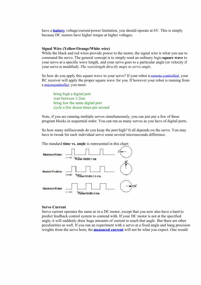
So how many milliseconds do you keep the port high? It all depends on the servo. You may
have to tweak for each individual servo some several microseconds difference.
The standard time vs. angle is represented in this chart:
Servo Current Servo current operates the same as in a DC motor, except that you now also have a hard to
predict feedback control system to contend with. If your DC motor is not at the specified
angle, it will suddenly draw huge amounts of current to reach that angle. But there are other peculiarities as well. If you run an experiment with a servo at a fixed angle and hang precision
weights from the servo horn, the measured current will not be what you expect. One would
8/6/2019 Actuator 1
http://slidepdf.com/reader/full/actuator-1 3/7
think that the current would increase at some fixed rate as the weights increased linearly.
Instead you will get unpredictable curves and multiple rates.
In conclusion, servo current draw is very unpredictable.
Stall Torque, Stall Current, Current Drain Since servos contain DC motors, please read my DC motor tutorial to learn about servo stall
characteristics.
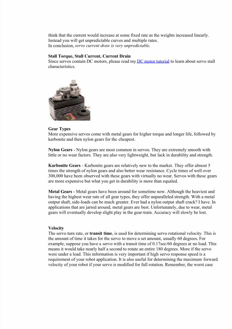
Gear Types More expensive servos come with metal gears for higher torque and longer life, followed by
karbonite and then nylon gears for the cheapest.
Nylon Gears - Nylon gears are most common in servos. They are extremely smooth with
little or no wear factors. They are also very lightweight, but lack in durability and strength.
Karbonite Gears - Karbonite gears are relatively new to the market. They offer almost 5
times the strength of nylon gears and also better wear resistance. Cycle times of well over 300,000 have been observed with these gears with virtually no wear. Servos with these gears
are more expensive but what you get in durability is more than equaled.
Metal Gears - Metal gears have been around for sometime now. Although the heaviest and
having the highest wear rate of all gear types, they offer unparalleled strength. With a metal
output shaft, side-loads can be much greater. Ever had a nylon output shaft crack? I have. In
applications that are jarred around, metal gears are best. Unfortunately, due to wear, metalgears will eventually develop slight play in the gear-train. Accuracy will slowly be lost.
Velocity
The servo turn rate, or transit time, is used for determining servo rotational velocity. This isthe amount of time it takes for the servo to move a set amount, usually 60 degrees. For
example, suppose you have a servo with a transit time of 0.17sec/60 degrees at no load. This
means it would take nearly half a second to rotate an entire 180 degrees. More if the servowere under a load. This information is very important if high servo response speed is a
requirement of your robot application. It is also useful for determining the maximum forward
velocity of your robot if your servo is modified for full rotation. Remember, the worst case
8/6/2019 Actuator 1
http://slidepdf.com/reader/full/actuator-1 4/7
turning time is when the servo is at the minimum rotation angle and is then commanded to go
to maximum rotation angle, all while under load. This can take several seconds on a very high
torque servo.
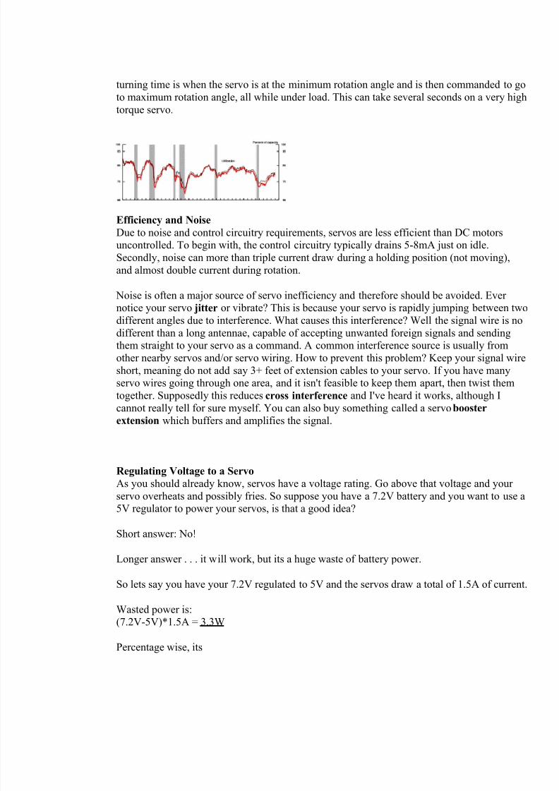
Efficiency and Noise
Due to noise and control circuitry requirements, servos are less efficient than DC motorsuncontrolled. To begin with, the control circuitry typically drains 5-8mA just on idle.
Secondly, noise can more than triple current draw during a holding position (not moving),
and almost double current during rotation.
Noise is often a major source of servo inefficiency and therefore should be avoided. Ever notice your servo jitter or vibrate? This is because your servo is rapidly jumping between two
different angles due to interference. What causes this interference? Well the signal wire is no
different than a long antennae, capable of accepting unwanted foreign signals and sendingthem straight to your servo as a command. A common interference source is usually from
other nearby servos and/or servo wiring. How to prevent this problem? Keep your signal wire
short, meaning do not add say 3+ feet of extension cables to your servo. If you have manyservo wires going through one area, and it isn't feasible to keep them apart, then twist them
together. Supposedly this reduces cross interference and I've heard it works, although I
cannot really tell for sure myself. You can also buy something called a servo booster
extension which buffers and amplifies the signal.
Regulating Voltage to a Servo
As you should already know, servos have a voltage rating. Go above that voltage and your
servo overheats and possibly fries. So suppose you have a 7.2V battery and you want to use a5V regulator to power your servos, is that a good idea?
Short answer: No!
Longer answer . . . it will work, but its a huge waste of battery power.
So lets say you have your 7.2V regulated to 5V and the servos draw a total of 1.5A of current
Wasted power is:(7.2V-5V)*1.5A = 3.3W
Percentage wise, its
8/6/2019 Actuator 1
http://slidepdf.com/reader/full/actuator-1 5/7
(7.2V-5V)/7.2V = 30.6%
Thats the battery energy percentage wasted to thermal heat - almost 1/3rd!!!
Speaking of heat, your voltage regulator probably has thermal shutdown, meaning that if itoverheats it will throttle down current to your servos - meaning your servos will have lower
torque and lower speed. If your voltage regulator doesn't have thermal shutdown, it will justfry instead (not a good thing).
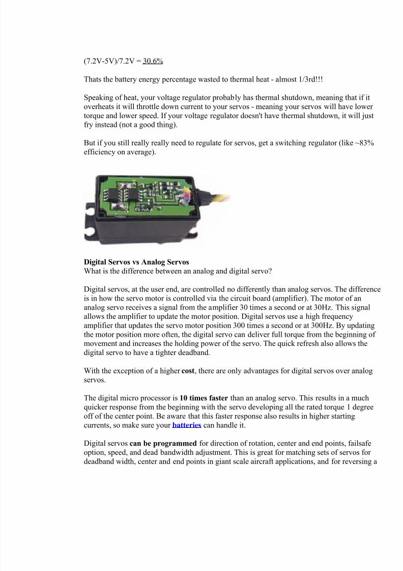
But if you still really really need to regulate for servos, get a switching regulator (like ~83%
efficiency on average).
Digital Servos vs Analog Servos What is the difference between an analog and digital servo?
Digital servos, at the user end, are controlled no differently than analog servos. The difference
is in how the servo motor is controlled via the circuit board (amplifier). The motor of ananalog servo receives a signal from the amplifier 30 times a second or at 30Hz. This signalallows the amplifier to update the motor position. Digital servos use a high frequency
amplifier that updates the servo motor position 300 times a second or at 300Hz. By updating
the motor position more often, the digital servo can deliver full torque from the beginning of movement and increases the holding power of the servo. The quick refresh also allows the
digital servo to have a tighter deadband.
With the exception of a higher cost, there are only advantages for digital servos over analog
servos.
The digital micro processor is 10 times faster than an analog servo. This results in a muchquicker response from the beginning with the servo developing all the rated torque 1 degree
off of the center point. Be aware that this faster response also results in higher starting
currents, so make sure your batteries can handle it.
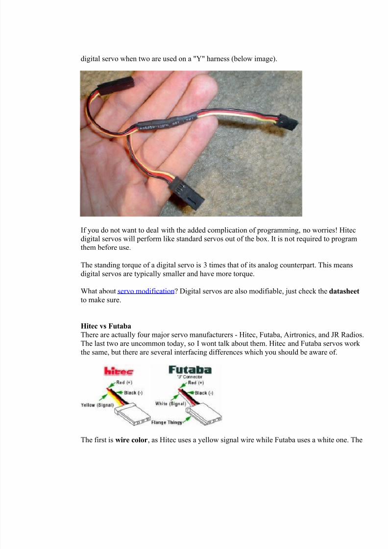
Digital servos can be programmed for direction of rotation, center and end points, failsafe
option, speed, and dead bandwidth adjustment. This is great for matching sets of servos for
deadband width, center and end points in giant scale aircraft applications, and for reversing a
8/6/2019 Actuator 1
http://slidepdf.com/reader/full/actuator-1 6/7
digital servo when two are used on a "Y" harness (below image).
If you do not want to deal with the added complication of programming, no worries! Hitecdigital servos will perform like standard servos out of the box. It is not required to program
them before use.
The standing torque of a digital servo is 3 times that of its analog counterpart. This means
digital servos are typically smaller and have more torque.
What about servo modification? Digital servos are also modifiable, just check the datasheetto make sure.
Hitec vs Futaba There are actually four major servo manufacturers - Hitec, Futaba, Airtronics, and JR Radios.
The last two are uncommon today, so I wont talk about them. Hitec and Futaba servos work
the same, but there are several interfacing differences which you should be aware of.
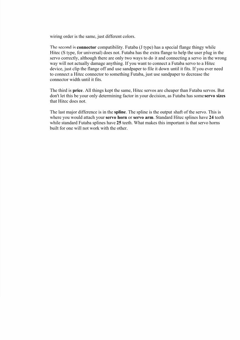
The first is wire color, as Hitec uses a yellow signal wire while Futaba uses a white one. The
8/6/2019 Actuator 1
http://slidepdf.com/reader/full/actuator-1 7/7
wiring order is the same, just different colors.
The second is connector compatibility. Futaba (J type) has a special flange thingy while
Hitec (S type, for universal) does not. Futaba has the extra flange to help the user plug in the
servo correctly, although there are only two ways to do it and connecting a servo in the wrongway will not actually damage anything. If you want to connect a Futaba servo to a Hitec
device, just clip the flange off and use sandpaper to file it down until it fits. If you ever need
to connect a Hitec connector to something Futaba, just use sandpaper to decrease theconnector width until it fits.
The third is price. All things kept the same, Hitec servos are cheaper than Futaba servos. But
don't let this be your only determining factor in your decision, as Futaba has some servo sizes
that Hitec does not.
The last major difference is in the spline. The spline is the output shaft of the servo. This is
where you would attach your servo horn or servo arm. Standard Hitec splines have 24 teethwhile standard Futaba splines have 25 teeth. What makes this important is that servo horns
built for one will not work with the other.