Embed Size (px)
Citation preview
1
flowserve.com
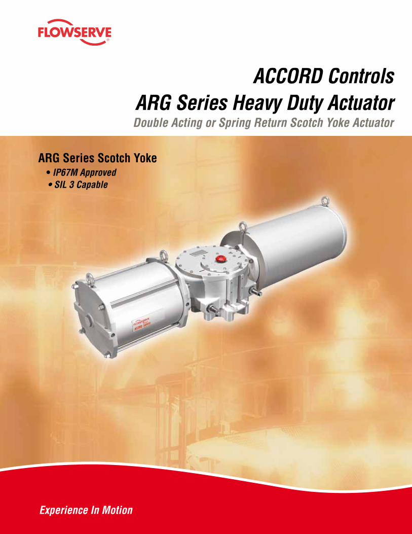
ACCORD ControlsARG Series Heavy Duty ActuatorDouble Acting or Spring Return Scotch Yoke Actuator
®
ARG Series Scotch Yoke • IP67M Approved • SIL 3 Capable
2
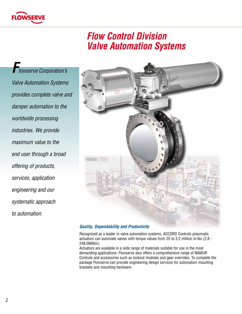
Flow Control DivisionValve Automation Systems
Flowserve Corporation’s
Valve Automation Systems
provides complete valve and
damper automation to the
worldwide processing
industries. We provide
maximum value to the
end user through a broad
offering of products,
services, application
engineering and our
systematic approach
to automation.
Quality, Dependability and Productivity
Recognized as a leader in valve automation systems, ACCORD Controls pneumatic actuators can automate valves with torque values from 25 to 2.2 million in-lbs (2.8 - 248,566Nm). Actuators are available in a wide range of materials suitable for use in the most demanding applications. Flowserve also offers a comprehensive range of NAMUR Controls and accessories such as lockout modules and gear overrides. To complete the package Flowserve can provide engineering design services for automation mounting brackets and mounting hardware.

3
flowserve.com
Sales and service facilities
are strategically located in
industrial centers throughout
the world.
To Access Literature Online Every item in this catalog has a brochure containing a great deal of technical product detail. It’s easy to find… it’s free… and you do not need a password.
Do This:➊ Go to www.flowserve.com
➋ Click in the box that says “Literature”
➌ Enter keyword or literature number
➍ Click on “Search"
The most recent version of each product bulletin will be available on this site.
Once you have the PDF, you can: • read it • print it • download it • even e-mail it
AutoSize 4.0
Use AutoSize 4.0 to:
• Ensure accurate actuator sizing
• Simplify and save time sizing actuators
• Create project files and data sheets
• Perform engineering calculations
AutoSize 4.0Automation sizing and selection softwarehttp://www.flowserve.com
While reasonable attempts have been made to ensure the accuracy of the output from this program. Flowserve disclaims responsibility for the use of this program including but not limited to the
4
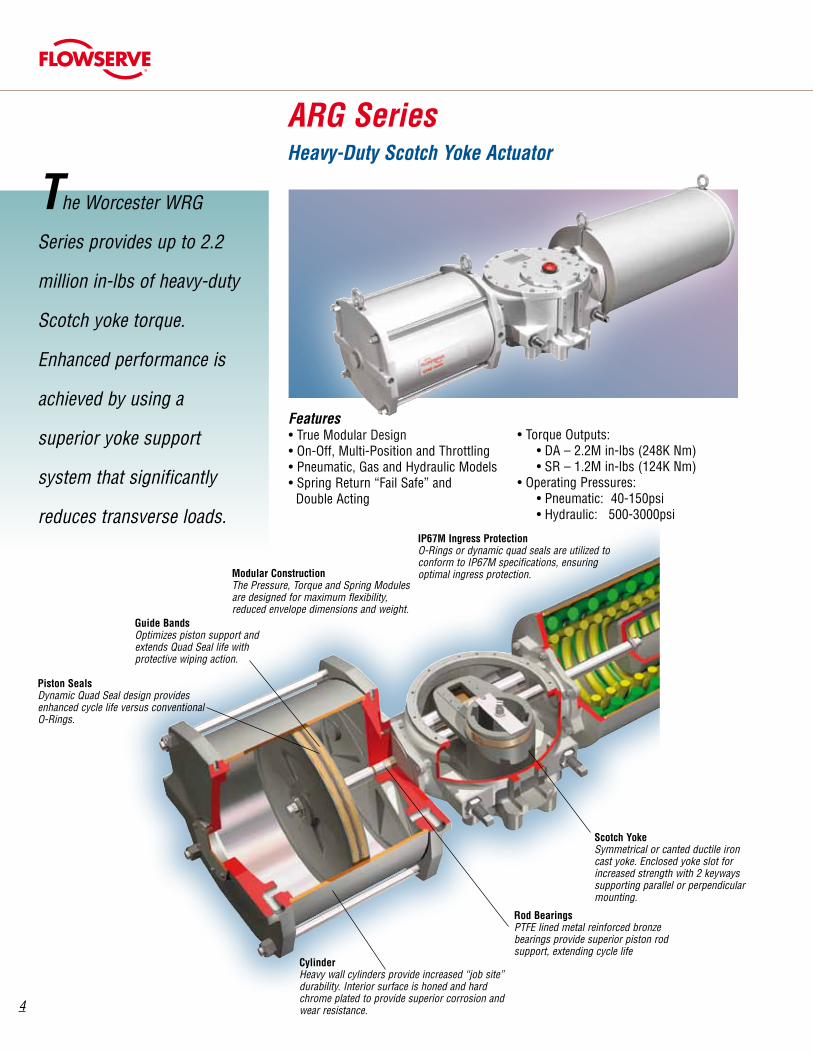
Piston SealsDynamic Quad Seal design provides enhanced cycle life versus conventional O-Rings.
Scotch YokeSymmetrical or canted ductile iron cast yoke. Enclosed yoke slot for increased strength with 2 keyways supporting parallel or perpendicular mounting.
Rod BearingsPTFE lined metal reinforced bronze bearings provide superior piston rod support, extending cycle life
CylinderHeavy wall cylinders provide increased “job site” durability. Interior surface is honed and hard chrome plated to provide superior corrosion and wear resistance.
Guide BandsOptimizes piston support and extends Quad Seal life with protective wiping action.
The Worcester WRG
Series provides up to 2.2
million in-lbs of heavy-duty
Scotch yoke torque.
Enhanced performance is
achieved by using a
superior yoke support
system that significantly
reduces transverse loads.
Features• True Modular Design• On-Off, Multi-Position and Throttling• Pneumatic, Gas and Hydraulic Models• Spring Return “Fail Safe” and Double Acting
ARG SeriesHeavy-Duty Scotch Yoke Actuator
IP67M Ingress ProtectionO-Rings or dynamic quad seals are utilized to conform to IP67M specifications, ensuring optimal ingress protection.Modular Construction
The Pressure, Torque and Spring Modules are designed for maximum flexibility, reduced envelope dimensions and weight.
• Torque Outputs: • DA – 2.2M in-lbs (248K Nm) • SR – 1.2M in-lbs (124K Nm)• Operating Pressures: • Pneumatic: 40-150psi • Hydraulic: 500-3000psi
5
flowserve.com
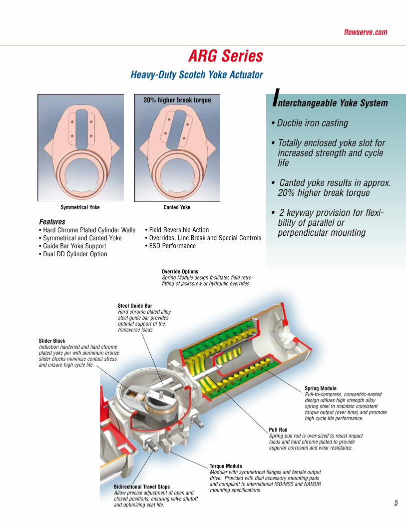
Pull RodSpring pull rod is over-sized to resist impact loads and hard chrome plated to provide superior corrosion and wear resistance.
Spring ModulePull-to-compress, concentric-nested design utilizes high strength alloy spring steel to maintain consistent torque output (over time) and promote high cycle life performance.
ARG SeriesHeavy-Duty Scotch Yoke Actuator
Override OptionsSpring Module design facilitates field retro-fitting of jackscrew or hydraulic overrides
Bidirectional Travel StopsAllow precise adjustment of open and closed positions, ensuring valve shutoff and optimizing seat life.
Torque ModuleModular with symmetrical flanges and female output drive. Provided with dual accessory mounting pads and compliant to international ISO/MSS and NAMUR mounting specifications
Features• Hard Chrome Plated Cylinder Walls• Symmetrical and Canted Yoke• Guide Bar Yoke Support• Dual DD Cylinder Option
Steel Guide BarHard chrome plated alloy steel guide bar provides optimal support of the transverse loads.
Interchangeable Yoke System
• Ductile iron casting
• Totally enclosed yoke slot for increased strength and cycle life
• Canted yoke results in approx. 20% higher break torque
• 2 keyway provision for flexi-bility of parallel or perpendicular mounting
Symmetrical Yoke Canted Yoke
Slider BlockInduction hardened and hard chrome plated yoke pin with aluminum bronze slider blocks minimize contact stress and ensure high cycle life.
20% higher break torque
• Field Reversible Action• Overrides, Line Break and Special Controls• ESD Performance

6
Modular Construction
ARG SeriesHeavy-Duty Scotch Yoke Actuator
DA Endplate
DD Double Acting Dual Cylinder
DA Direct Drive Jackscrew
DA Bevel Gear Jackscrew
DA Hydraulic Override
SR Spring Module
SR Direct Drive Jackscrew
SR Bevel Gear Jackscrew
SR Hydraulic Override
SR with DirectDrive Jackscrew
DA with HydraulicOverride Cylinder
Pneumatic Pressure Module
Hydraulic Pressure Module
• Double Acting or Spring Return (FCW or FCCW)
• Pneumatic or Hydraulic Pressure Modules
• Torque Module with symmetrical or canted yokes
• Override Options – Direct Drive Jackscrew, Bevel Gear Jackscrew or Hydraulic Override
Accessories

7
flowserve.com
Actuator Dimensions, mm (inch)Series A B C D E F I J K L M N X Y Q S P
ARG1 141(5.55)
310(12.20)
498(19.61)
18,5(0.73)
264(10.39)
55(2.17)
99(3.90)
129(5.08)
610,5(24.04)
1090(42.91)
902(35.51)
282(11.10)
68(2.68)
50(1.97)
9(0.35)
60(2.36)
30(1.18)
ARG2 162(6.38)
368(14.49)
586(23.07)
20(0.79)
322(12.68)
65(2.56)
116(4.57)
144(5.67)
712(28.03)
1278(50.31)
1060(41.73)
324(12.76)
68(2.68)
50(1.97)
8(0.31)
60(2.36)
30(1.18)
ARG3 175(6.98)
444(17.48)
706(27.80)
23(0.91)
380(14.96)
75(2.95)
111(4.37)
151(5.94)
817(32.17)
1500(59.06)
1238(48.74)
350(13.78)
95(3.74)
50(1.97)
15(0.59)
110(4.33)
45(1.77)
ARG4 243(9.57)
565(22.24)
868(34.17)
23(0.91)
467(18.39)
91(3.58)
145(5.71)
175(6.89)
1074(42.28)
1919(75.55)
1616(63.62)
486(19.13)
95(3.74)
70(2.76)
0(0.00)
110(4.33)
55(2.17)
ARG5 312(12.28)
716(28.19)
1008(39.69)
26(1.02)
568(22.36)
145(5.71)
175,5(6.91)
189,5(7.46)
1366(53.78)
2348(92.44)
2056(80.94)
624(24.57)
95(3.74)
70(2.76)
15.5(0.61)
110(4.33)
55(2.17)
ARG6 394(15.51)
756(29.76)
1640(64.57)
28(1.10)
600(23.62)
185(7.28)
208(8.19)
218(8.58)
1572(61.89)
3184(125.35)
2300(90.55)
788(31.02)
95(3.74)
70(2.76)
25.5(1.00)
110(4.33)
55(2.17)
ARG7 500(19.69)
810(31.89)
2030(79.92)
50(1.97)
615(24.21)
220(8.66)
265(10.43)
310(12.20)
1860(73.23)
3840(151.18)
2620(103.18)
1000(39.37)
266(10.47)
150(5.91)
11.5(0.45)
260(10.24)
130(5.12)
ARG8 665(26.18)
860(33.86)
2600(102.36)
55(2.17)
680(26.77)
280(11.02)
306(12.05)
360(14.17)
2245(88.39)
4790(188.58)
3050(120.08)
133052.36)
266(10.47)
200(7.87)
21(0.83)
260(10.24)
130(5.12)
Cylinder Size 5" 6" 7" 8" 9" 10" 12" 14" 16' 18" 20" 22" 24" 28" 32" 36" 40"
G 178(7.01)
178(7.01)
196(7.72)
222(8.74)
248(9.76)
274(10.79)
324(12.76)
375(14.76)
438(17.24)
486(19.13)
532(20.94)
588(23.15)
648(25.51)
865(34.06)
967(38.07)
1069(42.09)
1170(46.06)
Z Dimension "Z" upon Request
Port Size NPT 3/8˝ 3/8˝ 3/8˝ 3/8˝ 3/8˝ 1/2˝ 3/4˝ 3/4˝ 3/4˝ 1˝ 1˝ 1˝ 1˝ 1½˝ 1½˝ 1½˝ 2˝
Dimensions F
Side View
Double Acting Dual CylinderDouble Acting Single Cylinder
NPT Air Ports
NPT Air Ports
Spring Return
L
N
A A
BC
G E
J
I
G
MN
A AB
G
B
K
BA A
N
D
Y QG
ZX
PS
"H" TAP X "V" DEPTH
Back view bolt pitchfor accessory mountings
I
8
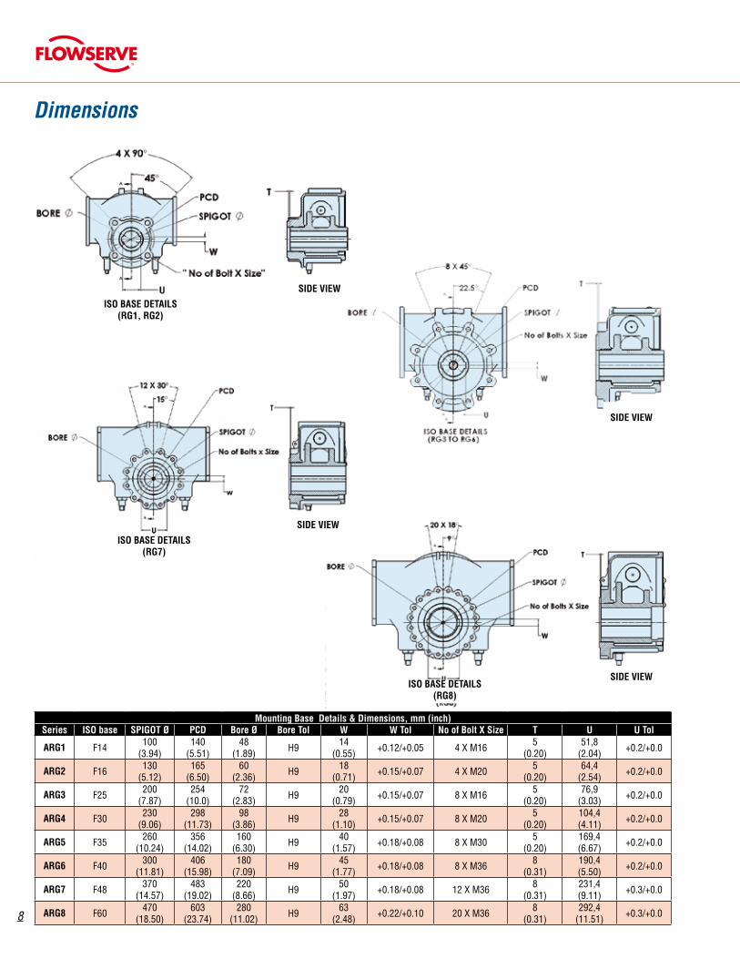
Mounting Base Details & Dimensions, mm (inch) Series ISO base SPIGOT Ø PCD Bore Ø Bore Tol W W Tol No of Bolt X Size T U U Tol
ARG1 F14 100(3.94)
140(5.51)
48(1.89) H9 14
(0.55) +0.12/+0.05 4 X M16 5(0.20)
51,8(2.04) +0.2/+0.0
ARG2 F16 130(5.12)
165(6.50)
60(2.36) H9 18
(0.71) +0.15/+0.07 4 X M20 5(0.20)
64,4(2.54) +0.2/+0.0
ARG3 F25 200(7.87)
254(10.0)
72(2.83) H9 20
(0.79) +0.15/+0.07 8 X M16 5(0.20)
76,9(3.03) +0.2/+0.0
ARG4 F30 230(9.06)
298(11.73)
98(3.86) H9 28
(1.10) +0.15/+0.07 8 X M20 5(0.20)
104,4(4.11) +0.2/+0.0
ARG5 F35 260(10.24)
356(14.02)
160(6.30) H9 40
(1.57) +0.18/+0.08 8 X M30 5(0.20)
169,4(6.67) +0.2/+0.0
ARG6 F40 300(11.81)
406(15.98)
180(7.09) H9 45
(1.77) +0.18/+0.08 8 X M36 8(0.31)
190,4(5.50) +0.2/+0.0
ARG7 F48 370(14.57)
483(19.02)
220(8.66) H9 50
(1.97) +0.18/+0.08 12 X M36 8(0.31)
231,4(9.11) +0.3/+0.0
ARG8 F60 470(18.50)
603(23.74)
280(11.02) H9 63
(2.48) +0.22/+0.10 20 X M36 8(0.31)
292,4(11.51) +0.3/+0.0
ISO BASE DETAILS(RG1, RG2)
ISO BASE DETAILS(RG3 to RG6)
ISO BASE DETAILS(RG7)
ISO BASE DETAILS(RG8)
SIDE VIEW
SIDE VIEW
SIDE VIEW
SIDE VIEW
Dimensions
9
flowserve.com
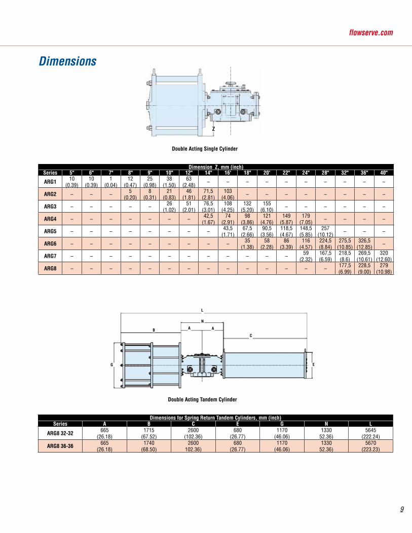
Dimension Z, mm (inch)Series 5" 6" 7" 8" 9" 10" 12" 14" 16' 18" 20' 22" 24" 28" 32" 36" 40"
ARG1 10(0.39)
10(0.39)
1(0.04)
12(0.47)
25(0.98)
38(1.50)
63(2.48) – – – – – – – – – –
ARG2 – – – 5(0.20)
8(0.31)
21(0.83)
46(1.81)
71,5(2.81)
103(4.06) – – – – – – – –
ARG3 – – – – – 26(1.02)
51(2.01)
76,5(3.01)
108(4.25)
132(5.20)
155(6.10) – – – – – –
ARG4 – – – – – – – 42,5(1.67)
74(2.91)
98(3,86)
121(4.76)
149(5.87)
179(7.05) – – – –
ARG5 – – – – – – – – 43,5(1.71)
67,5(2.66)
90,5(3.56)
118,5(4.67)
148,5(5.85)
257(10.12) – – –
ARG6 – – – – – – – – – 35(1.38)
58(2.28)
86(3.39)
116(4.57)
224,5(8.84)
275,5(10.85)
326,5(12.85) –
ARG7 – – – – – – – – – – – – 59(2.32)
167,5(6.59)
218,5(8.6)
269,5(10.61)
320(12.60)
ARG8 – – – – – – – – – – – – – – 177,5(6.99)
228,5(9.00)
279(10.98)
Z
Dimensions for Spring Return Tandem Cylinders, mm (inch)Series A B C E G N L
ARG8 32-32 665(26.18)
1715(67.52)
2600(102.36)
680(26.77)
1170(46.06)
133052.36)
5645(222.24)
ARG8 36-36 665(26.18)
1740(68.50)
2600102.36)
680(26.77)
1170(46.06)
133052.36)
5670(223.23)
B
N
C
A
G E
L
A
Dimensions
Double Acting Single Cylinder
Double Acting Tandem Cylinder
10
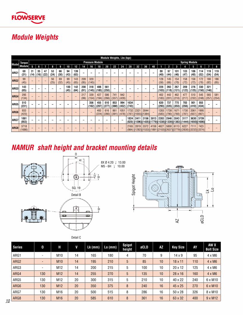
Module Weights, Lbs (kgs)
ModelTorque Module
Pressure Module Spring Module
5 6 7 8 9 10 12 14 16 18 20 22 24 28 32 36 40 1 2 3 4 5 6 7 8
ARG1 68(31)
31(14)
35(16)
47(22)
53(24)
66(30)
94(43)
139(63) – – – – – – – – – – 88
(40)97
(44)101(46)
103(47)
106(48)
114(52)
119(54)
119(54)
ARG2 99(45) – – – 56
(25)69
(32)99
(45)143(65)
209(95)
320(145) – – – – – – – – 128
(58)145(66)
154(70)
158(72)
158(72)
172(78)
180(82)
186(85)
ARG3 143(65) – – – – – 100
(45)142(64)
200(91)
318(145)
406(185)
561(255) – – – – – – 226
(103)260
(118)267
(121)269
(122)276
(125)330
(150)321
(146) –
ARG4 295(134) – – – – – – – 217
(99)339
(154)427
(194)586
(266)741
(337)942
(428) – – – – 402(183)
442(201)
462(210)
477(217)
510(232)
545(248)
565(257)
581(254)
ARG5 510(231) – – – – – – – – 356
(162)455
(207)610
(277)853
(388)994
(452)1634(743) – – – 639
(290)737
(335)770
(350)783
(356)901
(410)955
(434) – –
ARG6 933(423) – – – – – – – – – 493
(224)616
(280)861
(391)1051(478)
1732(787)
2321(1055)
3044(1384) – 1283
(583)1738(790)
1671(760)
1730(787)
2061(937)
1995(907) – –
ARG7 1881(853) – – – – – – – – – – – – – 1824
(829)2411
(1096)3156
(1435)3913
(1779)2283
(1038)2946
(1339)3043
(1383)3177
(1444)3630
(1650)3709
(1686) – –
ARG8 3718(1686) – – – – – – – – – – – – – 2165
(984)2819
(1282)3372
(1533)4159(1891
4627(2103)
5800(2637)
6113(2779)
6227(2830)
7111(3232)
7423(3374) – –
Module Weights
Series O H V Lk (mm) Lo (mm)Spigotheight
øCLD AZ Key Size AYAW X
Bolt Size
ARG1 - M10 14 165 180 4 70 9 14 x 9 95 4 x M6
ARG2 - M10 14 195 210 5 85 10 18 x 11 110 4 x M6
ARG3 - M12 14 200 215 5 100 10 20 x 12 125 4 x M6
ARG4 130 M12 14 255 270 5 135 10 28 x 16 160 4 x M6
ARG5 130 M12 20 300 315 5 210 10 40 x 22 240 6 x M10
ARG6 130 M12 20 350 375 8 240 16 45 x 25 270 6 x M10
ARG7 130 M16 20 500 515 8 286 16 50 x 28 326 8 x M10
ARG8 130 M16 20 585 610 8 361 16 63 x 32 400 9 x M12
Detail B
Detail C
SQ. 19
8X Ø 4.20 ↓ 13.00M5 - 6H ↓ 10.00
O80
40
15 30
30
NAMUR shaft height and bracket mounting details
Module Weights, Lbs (kgs)
ModelTorque Module
Pressure Module Spring Module
5 6 7 8 9 10 12 14 16 18 20 22 24 28 32 36 40 1 2 3 4 5 6 7 8
68(31)
31(14)
35(16)
47(22)
53(24)
66(30)
94(43)
139(63) – – – – – – – – – – 88
(40)97
(44)101(46)
103(47)
106(48)
114(52)
119(54)
119(54)
ARG2 99(45) – – – 56
(25)69
(32)99
(45)143(65)
209(95)
320(145) – – – – – – – – 128
(58)145(66)
154(70)
158(72)
158(72)
172(78)
180(82)
186(85)
143(65) – – – – – 100
(45)142(64)
200(91)
318(145)
406(185)
561(255) – – – – – – 226
(103)260
(118)267
(121)269
(122)276
(125)330
(150)321
(146) –
ARG4 295(134) – – – – – – – 217
(99)339
(154)427
(194)586
(266)741
(337)942
(428) – – – – 402(183)
442(201)
462(210)
477(217)
510(232)
545(248)
565(257)
581(254)
510(231) – – – – – – – – 356
(162)455
(207)610
(277)853
(388)994
(452)1634(743) – – – 639
(290)737
(335)770
(350)783
(356)901
(410)955
(434) – –
ARG6 933(423) – – – – – – – – – 493
(224)616
(280)861
(391)1051(478)
1732(787)
2321(1055)
3044(1384) – 1283
(583)1738(790)
1671(760)
1730(787)
2061(937)
1995(907) – –
1881(853) – – – – – – – – – – – – – 1824
(829)2411
(1096)3156
(1435)3913
(1779)2283
(1038)2946
(1339)3043
(1383)3177
(1444)3630
(1650)3709
(1686) – –
ARG8 3718(1686) – – – – – – – – – – – – – 2165
(984)2819
(1282)3372
(1533)4159(1891
4627(2103)
5800(2637)
6113(2779)
6227(2830)
7111(3232)
7423(3374) – –
Spig
ot H
eigh
t
AZ
Lk Lo
øCLD
11
flowserve.com
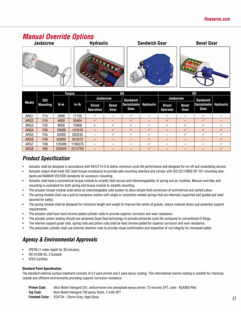
Product Specification• Actuator shall be designed in accordance with EN15714-3 to define minimum cycle life performance and designed for on-off and modulating service. • Actuator output shall meet ISO rated torque compliance to provide safe mounting interface and comply with ISO 5211/MSS SP-101 mounting stan-
dards and NAMUR VDI/VDE standards for accessory mounting. • Actuator shall have a symmetrical torque module to simplify field service and interchangeability of spring and air modules. Manual overrides and
mounting is consistent for both spring and torque module to simplify mounting. • The actuator torque module shall utilize an interchangeable yoke system to allow simple field conversion of symmetrical and canted yokes. • The spring module shall use a pull-to-compress motion with single or concentric-nested springs that are internally supported and guided and weld
secured for safety.• The spring module shall be designed for minimum length and weight to improve the center of gravity, reduce material stress and assembly support
requirements.• The actuator shall have hard chrome plated cylinder walls to provide superior corrosion and wear resistance. • The actuator piston sealing should use advanced Quad Seal technology to provide enhanced cycle life compared to conventional O-Rings.• The internal support guide rods, spring rods and piston rods shall be hard chrome plated for superior corrosion and wear resistance. • The pneumatic cylinder shall use external retention rods to provide visual confirmation and inspection of rod integrity for increased safety.
Agency & Environmental Approvals
• IP67M (1 meter depth for 30 minutes)• IEC 61508 SIL 3 Suitable• ATEX Certified
Standard Paint SpecificationThe standard external surface treatment consists of a 2 pack primer and 2 pack epoxy coating. This international marine coating is suitable for chemical, coastal and offshore environments providing superior corrosion resistance.
Primer Coat: Akzo Nobel Intergard 251, anticorrosive zinc phosphate epoxy primer, 75 microns DFT, color: KGA902-Red. Top Coat: Akzo Nobel Intergard 740 epoxy finish, 2 mills DFT Finished Color: ECK724 – Storm Grey, High Gloss
Manual Override Options
ModelISO
Mounting
Torque DA SR
N-m in-lb
Jackscrew Sandwich Declutchable
GearHydraulic
Jackscrew SandwichDeclutchable
GearHydraulicDirect
OperationBevelGear
DirectOperator
BevelGear
ARG1 F14 2000 17702 – – – –ARG2 F16 4000 35404 – – – –ARG3 F25 8000 70808
ARG4 F30 16000 141616 – –
ARG5 F35 32000 283232 – –
ARG6 F40 63000 557613 – – – – – –
ARG7 F48 125000 1106375 – – – – – –
ARG8 F60 250000 2212750 – – – – – –
Jackscrew Hydraulic Sandwich Gear Bevel Gear
12 FCD ACENBR0005-04 12/10 Printed in U.S.A. © Flowserve Corporation
Flowserve Corporation has established industry leadership in the design and manufacture of its products. When properly selected this Flowserve product is designed to perform its intended function safely during its useful life. However, the purchaser or user of Flowserve products should be aware that Flowserve products might be used in numerous applications under a wide variety of industrial service conditions. Although Flowserve can (and often does) provide general guidelines, it cannot provide specific data and warnings for all possible applications. The purchaser/user must therefore assume the ultimate responsibility for the proper sizing and selection, installation, operation, and maintenance of Flowserve products. The purchaser/user should read and understand the Installation Operation Maintenance (IOM) instructions included with the product, and train its employees and contractors in the safe use of Flowserve products in connection with the specific application.
While the information and specifications contained in this literature are believed to be accurate they are supplied for informative purposes only and should not be considered certified or as a guarantee of satisfactory results by reliance thereon. Nothing contained herein is to be construed as a warranty or guarantee, expressed or implied, regarding any matter with respect to this product. Because Flowserve is continually improving and upgrading its product design, the specifications, dimensions and information contained herein are subject to change without notice. Should any question arise concerning these provisions, the purchaser/user should contact Flowserve Corporation at any one of its worldwide operations or offices.
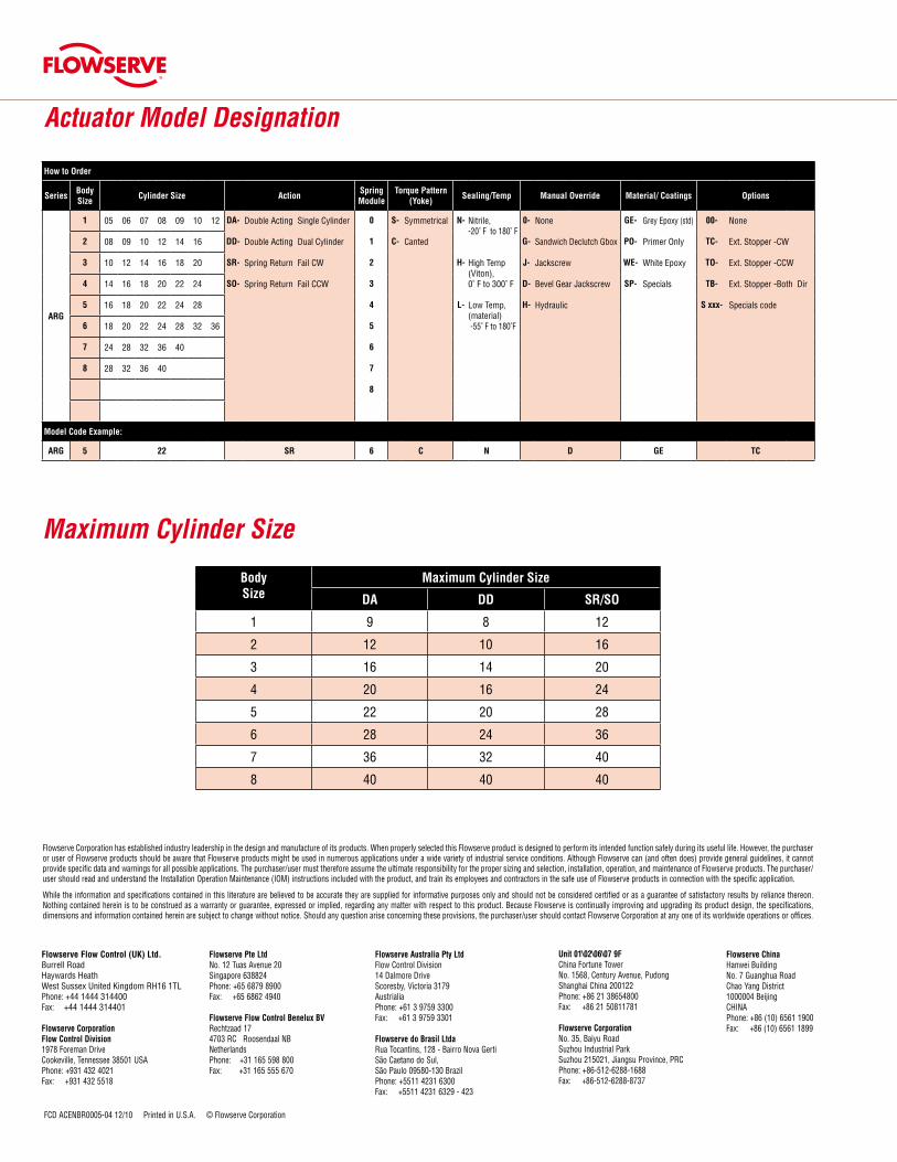
BodySize
Maximum Cylinder Size
DA DD SR/SO
1 9 8 12
2 12 10 16
3 16 14 20
4 20 16 24
5 22 20 28
6 28 24 36
7 36 32 40
8 40 40 40
Maximum Cylinder Size
Actuator Model Designation
How to Order
SeriesBody Size
Cylinder Size ActionSpring Module
Torque Pattern (Yoke)
Sealing/Temp Manual Override Material/ Coatings Options
ARG
1 05 06 07 08 09 10 12 DA- Double Acting Single Cylinder 0 S- Symmetrical N- Nitrile, -20˚ F to 180˚ F
0- None GE- Grey Epoxy (std) 00- None
2 08 09 10 12 14 16 DD- Double Acting Dual Cylinder 1 C- Canted G- Sandwich Declutch Gbox PO- Primer Only TC- Ext. Stopper -CW
3 10 12 14 16 18 20 SR- Spring Return Fail CW 2 H- High Temp (Viton), 0˚ F to 300˚ F
J- Jackscrew WE- White Epoxy TO- Ext. Stopper -CCW
4 14 16 18 20 22 24 SO- Spring Return Fail CCW 3 D- Bevel Gear Jackscrew SP- Specials TB- Ext. Stopper -Both Dir
5 16 18 20 22 24 28 4 L- Low Temp,(material) -55˚ F to 180˚F
H- Hydraulic S xxx- Specials code
6 18 20 22 24 28 32 36 5
7 24 28 32 36 40 6
8 28 32 36 40 7
8
Model Code Example:
ARG 5 22 SR 6 C N D GE TC
Flowserve Flow Control (UK) Ltd. Burrell Road Haywards HeathWest Sussex United Kingdom RH16 1TLPhone: +44 1444 314400Fax: +44 1444 314401
Flowserve CorporationFlow Control Division1978 Foreman DriveCookeville, Tennessee 38501 USAPhone: +931 432 4021Fax: +931 432 5518
Flowserve Pte LtdNo. 12 Tuas Avenue 20Singapore 638824Phone: +65 6879 8900Fax: +65 6862 4940
Flowserve Flow Control Benelux BVRechtzaad 174703 RC Roosendaal NBNetherlandsPhone: +31 165 598 800Fax: +31 165 555 670
Flowserve Australia Pty LtdFlow Control Division14 Dalmore DriveScoresby, Victoria 3179AustrialiaPhone: +61 3 9759 3300Fax: +61 3 9759 3301
Flowserve do Brasil LtdaRua Tocantins, 128 - Bairro Nova GertiSão Caetano do Sul,São Paulo 09580-130 BrazilPhone: +5511 4231 6300Fax: +5511 4231 6329 - 423
Unit 01\02\06\07 9FChina Fortune TowerNo. 1568, Century Avenue, PudongShanghai China 200122Phone: +86 21 38654800Fax: +86 21 50811781
Flowserve CorporationNo. 35, Baiyu RoadSuzhou Industrial ParkSuzhou 215021, Jiangsu Province, PRCPhone: +86-512-6288-1688Fax: +86-512-6288-8737
Flowserve ChinaHanwei BuildingNo. 7 Guanghua RoadChao Yang District1000004 BeijingCHINAPhone: +86 (10) 6561 1900Fax: +86 (10) 6561 1899