Embed Size (px)
Citation preview

IETTI-225 – Introduction to Programmable Devices (Semester 4 EXPERIMENTS)
NAME: Last update 20 March 2022
Activity # Due by session #12 Score01 Experiment Memory-based AWG02 Assessment Design and build loaded voltage divider circuit03 Assessment Design and build RC filter network
Activity # Due by session #24 Score04 Experiment Wired telemetry system05 Assessment Capture and manually interpret a serial data frame06 Assessment Troubleshoot wired telemetry system
Activity # Due by session #36 Score07 Experiment Radio telemetry system08 Assessment Build and test a custom inductor09 Assessment Troubleshoot radio telemetry system
Activity # Due by session #48 Score10 Experiment Switch-mode power conversion system11 Assessment Design and build a transistor amplifier with specified voltage gain12 Assessment Troubleshoot power conversion system
Activity # Due by the last day Score13 Experiment SCADA system14 Assessment Troubleshoot combinational logic controlled motor (simulation)15 Assessment Troubleshoot SCADA system
16 Lab clean-up Clean and organize the entire lab room
1

Essential information about this course:
• This is a laboratory course, but the experiments are multi-concept systems rather than single-concept
experiments.
• These experimental systems follow concepts taught in that semester’s theory course, which means thetheory course outline and source texts are essential resources for you here.
• Half of your course grade comes from the number of attempts necessary to correctly complete eachdemonstration. Clarifying questions are welcome, but all results presented to the instructor will beassessed just like answers submitted on an exam.
• Half of your course grade comes from the number of attempts necessary to correctly complete eachassessment activity (e.g. skills demonstrations and circuit troubleshooting). Just like the experiments,each assessment activity must be eventually completed correctly to pass the course.
• You should budget a minimum of 12 hours per week for this course. The lab is yours to use during allopen-school hours. Do not let the lack of fixed hours for this course lead to procrastination – manage
your time wisely!
• Successful students (1) review relevant theory before planning experimental systems, (2) read systemrequirements carefully, (3) set reasonable goals, and (4) prioritize hands-on lab time.
EET Program Learning Outcomes
(1) COMMUNICATION and TEAMWORK – Accurately communicate ideas across a variety of media(oral, written, graphical) to both technical and non-technical audiences; Function effectively as a member ofa technical team.
(2) SELF-MANAGEMENT – Arrive on time and prepared; Work diligently until the job is done; Budgetresources appropriately to achieve objectives.
(3) SAFE WORK HABITS – Comply with relevant national, state, local, and college safety regulationswhen designing, prototyping, building, and testing systems.
(4) ANALYSIS and DIAGNOSIS – Select and apply appropriate principles and techniques for bothqualitative and quantitative circuit analysis; Devise and execute appropriate tests to evaluate electronicsystem performance; Identify root causes of electronic system malfunctions.
(5) PROBLEM-SOLVING – Devise and implement solutions for technical problems appropriate to thediscipline.
(6) DOCUMENTATION – Interpret and create technical documents (e.g. electronic schematic diagrams,block diagrams, graphs, reports) relevant to the discipline.
(7) INDEPENDENT LEARNING – Select and research information sources to learn new principles,technologies, and/or techniques.
file eet_outcomes
2

Values
This educational program exists for one purpose: to empower you with a comprehensive set of knowledge,skills, and habits to unlock opportunities in your chosen profession. The following values articulate personalattitudes guaranteed to fulfill this purpose, and the principles upon which this program is designed. Theyembody what I like to call a strong learning ethic, similar to a strong work ethic but applied to the learningprocess rather than a job.
Ownership – you are the sole proprietor of your education, of your career, and to a great extent yourquality of life. No one can force you to learn, make you have a great career, or grant you a fulfilling life –these accomplishments are possible only when you accept responsibility for them.
Responsibility – ensuring the desired outcome, not just attempting to achieve the outcome. Responsibilityis how we secure rights and privileges.
Initiative – independently recognizing needs and taking responsibility to meet them.
Integrity – living in a consistently principled manner, communicating clearly and honestly, applying yourbest effort, and never trying to advance at the expense of others. Integrity is the key to trust, and trust isthe glue that binds all relationships personal, professional, and societal.
Perspective – prioritizing your attention and actions to the things we will all care about for years to come.Never letting short-term concerns eclipse the long-term.
Humility – no one is perfect, and there is always something new to learn. Making mistakes is a symptomof living, and for this reason we need to be gracious to ourselves and to others.
Safety – assessing hazards and avoiding unnecessary risk to yourself and to others.
Competence – your ability to consistently and independently apply knowledge and skill to the solution ofpractical problems. Competence includes the ability to verify the appropriateness of your solutions and theability to communicate so that others understand how and why your solutions work.
Diligence – exercising self-discipline and persistence in learning, accepting the fact there is no easy way toabsorb complex knowledge, master new skills, or overcome limiting habits. Diligence in work means the jobis not done until it is done correctly: all objectives achieved, all documentation complete, and all root-causesof problems identified and corrected.
Community – your actions impact other peoples’ lives, for good or for ill. Conduct yourself not just foryour own interests, but also for the best interests of those whose lives you affect.
Respect is the acknowledgment of others’ intrinsic capabilities, responsibilities, and worth. Everyone hassomething valuable to contribute, and everyone deserves to fully own their lives.
file eet_values
3

Course description
This course teaches the application of electronic principles learned in IETTI-223 (Advanced ElectronicsII) by way of project design and construction, skill demonstrations, and troubleshooting faulted projects.Mastery standards applied to all experimental and diagnostic steps guarantee attainment of learningoutcomes.
Course learning outcomes
• Design, construct, document, and test complex electronic systems based on general specificationsand high-level design ideas developed in partnership with the instructor, these systems incorporatingprogrammable memory, serial data communication networks, RF, power conversion circuits, andfeedback control loops. (Addresses Program Learning Outcomes 1, 2, 3, 4, 5, 6, 7)
• Troubleshoot faulted wired telemetry systems, wireless telemetry systems, power conversion circuits,and feedback control systems from measurements taken at test points with circuit components andconnections hidden from view. (Addresses Program Learning Outcomes 4, 6)
• Articulate diagnostic reasoning while troubleshooting these same circuits. (Addresses Program LearningOutcomes 1, 3)
4

Required Tools, Supplies, and Software
Listed by IETTI course number and course type (Thy = theory, Exp = Experiments, Prj = Projects).
Semester 1 = IETTI-101 (Theory), 103 (Experiments), and 102 (Projects)Semester 2 = IETTI-104 (Theory), 112 (Experiments), and 105 (Projects)Semester 3 = IETTI-222 (Theory), 221 (Experiments), and 220 (Projects)Semester 4 = IETTI-223 (Theory), 225 (Experiments), and 106 (Projects)
Tool, Supply, or Software Thy Exp Prj Thy Exp Prj Thy Exp Prj Thy Exp Prjinstallation 101 103 102 104 112 105 222 221 220 223 225 106
$25 scientific calculator X X X X X X X X X X X XComplex number math functions X X
$300 personal computer X X X X X X X X X X X Xany OS, not tablet
$10 USB “flash” drive X X X X X X X X X X X X$50-$100 digital multimeter X X X X X X X X
$400 optional upgrade: Fluke 87-V + + + + + +$300 optional upgrade: Simpson 260 + + + + + +
$150 USB-based oscilloscope X X X X X X X Xe.g. Picoscope model 2204A
Camera (mobile phone okay) X X X X X X X X$10 solderless breadboard X X X X X X X X$25 grounding wrist strap X X X X X X X X
$10 jeweler’s screwdriver set X X X X X X X X$10 wire strippers, 18-24 AWG X X X X X X X X
$10 needle-nose pliers X X X X X X X X$20 diagonal wire cutters X X X X X X X X
$10 alligator-clip jumper wires X X X X X X X X(package of at least ten)
$15 batteries: 6 Volt and 9 Volt X X X X X X X X$15 illuminated jeweler’s loupe X X X X X X X X
$10 safety glasses X X X X X$25-$100 soldering iron (pencil-tip), X X X X X
30 Watts or less$15 tube/spool of rosin-core solder X X X X X
$0 software: schematic editor X X X X X X X X$0 software: Notepad++ text editor X X X X$0 software: NGSPICE circuit sim. X X X X
$0 software: WSL X X X X(Windows Subsystem for Linux)$0 software: tshoot fault sim. X X X X
$15 microcontroller development kit X X X Xand IDE software
$0 software: PCB layout editor X X$0 software: packet-sniffing software X X X
5

Required Tools, Supplies, and Software
Scientific calculator – at minimum your calculator must perform trigonometric functions (sine, cosine,tangent, etc.), offer multiple memory registers, and display values in both scientific and “engineering”notations. I recommend the Texas Instruments model TI-36X Pro because it easily performs complex-number arithmetic necessary for AC circuit analysis and is inexpensive.
Personal computer – all course materials are available in electronic format and are free (most are alsoopen-source), making a portable computer extremely useful. The school provides personal computers foron-campus use, but having your own will enable you to work outside of school. Any operating system, anysize hard drive, any amount of RAM memory, and any screen size is appropriate. Useful features worthhigher cost include an RJ-45 Ethernet port and an EIA/TIA-232 (9-pin) serial port.
Multimeter – this is your first and most important electronic test instrument. At minimum it mustmeasure DC and AC voltage, DC and AC current (milliAmpere range), resistance, and “diode check”voltage drop. Useful features worth higher cost include microAmpere current measurement, true-RMS ACmeasurement (for second-semester courses and above), frequency measurement, capacitance measurement,and minimum/maximum value capture. Cost is a strong function of accuracy, frequency range, and safety(“Category” ratings for over-voltage exposure). The Fluke model 87-V is an excellent professional-gradechoice for digital multimeters, and the Simpson 260 is an excellent professional-grade choice for analogmultimeters. Note that Fluke offers a 25% educational discount for students.
Oscilloscope – once too expensive for student purchase, entry-level USB-based oscilloscopes now costless than a textbook. Pico Technology is an excellent brand, and their model 2204A comes with high-quality probes as well. Plugged into your personal computer using a USB cable, the Picoscope turns yourcomputer’s monitor into a high-resolution oscilloscope display. Features include two measurement channels,10 MHz bandwidth, built-in arbitrary waveform generator (AWG), ± 100 Volt over-voltage protection,digital “cursors” for precise interpretation of amplitude and frequency, meter-style measurement capability,Fast Fourier Transform algorithm for frequency-domain measurement, export ability to several graphicimage formats as well as comma-separated variable (.csv) files, and serial communications signal decoding.Together with your multimeter, solderless breadboard and Development Board (which you will construct inthe IETTI-102 Project course and is yours to keep) this forms a complete electronics laboratory for doingexperiments and projects outside of school.
Soldering – the equipment you purchase for soldering need not be expensive, if you purchase the rightsolder. For electronics work you must use rosin-core solder. Kester is an excellent brand, and you shouldavoid cheap imported solders. For lead-based solder, a 63% tin and 37% lead alloy (Sn63/Pb37) works verywell. A one-pound roll is likely more solder than you will need in these courses, so I recommend buying justa small tube or small roll. I recommend a fine-tipped soldering iron (15 Watts continuous power, althoughsome with adjustable temperature controls may have higher power ratings to get up to soldering temperaturemore quickly) and a solder diameter 0.031 inches or smaller for doing fine printed-circuit board work. Also,keep the tip of your soldering iron clean by wiping it against a damp sponge or paper towel when hot, andnot leaving it hot any longer than necessary. Hakko, X-tronic, and Lonove are all recommended brands.
Microcontroller – these courses are not brand- or model-specific, but the Texas Instruments MSP430 seriesis highly recommended for their powerful features, modern design, and programmability in multiple languages(assembly, C, C++, and Sketch). I particularly recommend the model MSP-EXP430G2ET “LaunchPad”development board (MSP430G2553IN20 microcontroller chip) with Code Composer Studio for the IDEsoftware. A hobbyist-grade microcontroller such as the popular Arduino and Parallax BASIC Stamp arepermissible only in first-year courses, but not in second-year courses.
6

Required Tools, Supplies, and Software
All software required for these courses is free, and some of it is open-source.
Schematic editor – this is used to draft schematic diagrams for circuits. A good one is TinyCAD, but thereare also web-based CAD tools such as circuitlab.com that are very effective and easy to use.
Text editor – this is used to create plain-text files, kind of like a word processor but lacking formattingfeatures such as typeface, font size, etc. It is absolutely necessary for writing code of any kind. Notepad++
is a very good editor, but others work well too.
NGSPICE – this is a modern adaptation of the venerable SPICE circuit simulator which uses a text-coded“netlist” rather than a visual schematic diagram to describe circuits. Very powerful, and with decadesof netlist examples from earlier versions of SPICE to use as references. The installer lacks sophistication,being nothing more than a compressed (zip) file that you unpack. Once installed, you should instruct yourcomputer’s operating system to automatically associate any files ending in the extension .cir with theNGSPICE executable file ngspice.exe so that all of your netlist files will appear with the NGSPICE iconand will automatically load into NGSPICE when double-clicked.
WSL – Windows Subsystem for Linux is a “virtual machine” Linux operating system that runs within theWindows operating system, giving you a command-line user environment mimicking that of a Unix operatingsystem. It is a free application from Microsoft, with instructions available from Microsoft on how to install.I recommend installing the “Debian” distribution of WSL. Once installed, you will issue these commands inthe following order to install all the necessary programming tools:• sudo apt update
• sudo apt install build-essential
• sudo apt install indent
• sudo apt install python3
tshoot – this is a specialized circuit-simulator program that inserts faults into circuits and tests your abilityto locate them. The download consists of a single “tar” archive file which you must unpack and compileusing the following two commands within a Unix-type operating system or within WSL. The fourth commandlisted below starts and runs the application:• mkdir tshoot ; mv -v *.tar tshoot ; cd tshoot
• tar xvf *.tar
• make
• ./tshoot
IDE software – an “Integrated Development Environment” is a software package used to write code, andfor our purposes this would be code meant to run in a microcontroller. For the Texas Instruments MSP430series, the main IDE is called Code Composer Studio, and it supports programming in assembly language,C, and C++. A third-party add-on to Code Composer Studio called Energia supports programming in theSketch language, identical to that used by the popular Arduino microcontroller series.
PCB layout editor – this is specialized drafting software intended for creating graphic files to be sent toprinted circuit board (PCB) manufacturers so you can order your own custom PCBs. PCB Artist is free andexceptionally easy to use, but only exports files to the manufacturer Advanced Circuits. Free PCB layouteditors capable of exporting “Gerber” format files which are universally accepted by PCB manufacturersinclude EasyEDA, KiCAD (very powerful but hard to learn), and pcb. Of these I recommend EasyEDA forbeginners, or PCB Artist if you don’t mind being locked into one manufacturing option.
Packet-sniffing software – this is specialized software for monitoring network communications. Anexcellent (and free) option is Wireshark.
file eet_tools
7

Grading standards for Experiment courses
Your grade for this course is based on percentage scores (in every calculation rounded down to whole-numbered values), with each category weighted as follows:
• Experiment scores = 50% (Note: all Experiments are mastery-based, which means they must beeventually completed at 100% competence in order to pass the course)
• Assessment scores = 50% (Note: all Assessments are mastery-based, which means they must beeventually completed at 100% competence in order to pass the course)
Please note the importance of completing all Experiments and all Assessments on or before their respectivedeadline dates. If any Experiment or Assessment is incomplete by the end of the school day of the deadlinedate, it will receive a 0% score. If any Experiment or Assessment is incomplete by the end of the last dayof the course, you will earn a failing grade (F) for the course. All Experiments and Assessments must becomplete by the end of the last day of the course to receive a passing grade for the course.
Carefully follow the instructions associated with each experiment! If there is a prescribed order, youmust follow this order of steps or else you will receive a 0% score for that experiment. The same is true ifyou plagiarize any part of it (i.e. present someone else’s work as your own). For every experiment there willbe multiple demonstrations, explanations, and/or challenges you must complete in the instructor’s presence,and these are all mastery-based which means they all must be completed with 100% competence. Multipleopportunities are given to master each, with a point deduction levied for every re-try. You are welcome andencouraged at any time to seek clarification from the instructor so that you understand what is being askedof you, but you are solely responsible for doing the work and solving the problems. This is similar to thepolicy during written exams in a Theory course: the instructor will happily clarify expectations, but willnot solve the problems for you nor confirm if an answer is correct prior to scoring it.
Electronic submissions of Experiments and Assessments are acceptable for full credit. The standards are justas high for electronic submissions as for face-to-face demonstrations. For Experiments, video documentationof you completing all objectives in their proper order will count as full credit. For Assessments your workmust either be videorecorded in one seamless take or performed on a live video stream so the instructor isable to ensure you are doing the work yourself with no aid.
This course is based on experiments and hands-on assessments, and does not have scheduled meeting timesas is the case with instructor-facilitated theory sessions. However, your punctual and consistent attendanceis important for your success, as these activities require significant time-on-task to complete.
If you must be late or absent, it is imperative that you contact your instructor as well as any classmates youmay be coordinating with so plans may be adjusted. It is still your responsibility to meet all deadlines.
A failing (F) grade will be earned for the entire course if any experiment or assessment is not completed onor before the deadline date, or for any of the following behaviors: false testimony (lying), cheating on anyassignment or assessment, plagiarism (presenting another’s work as your own), willful violation of a safetypolicy, theft, harassment, sabotage, destruction of property, or intoxication. These behaviors are groundsfor immediate termination in this career, and as such will not be tolerated here.
file eet_grading_e
8

01 Experiment
NAME: DUE DATE:
Design and build an experimental arbitrary waveform generator using a nonvolatile memory IC to storenumerical values describing the instantaneous amplitudes of a waveform at multiple points throughout itsperiod. A counter will drive the address lines of the memory IC, and with the stored digital data driving adigital-to-analog converter to produce the waveform.
Block diagram:
Counter ROM DACClockArbitrary waveform
output
Instructor consultation – Discuss general plan, components available, safety considerations, etc.Document this in the “engineering notebook” document, and be sure to record all data here, even frommistakes!
Stand-alone demonstrations (may be completed in any order; −5% per re-try, each):
Instructor certifies – Demonstrate and record a functioning clock pulse circuit suitable for driving thecounter.
Instructor certifies – Demonstrate a functioning counter circuit suitable for driving the memory IC.
Instructor certifies – Interpret timing diagrams given in memory IC datasheet for both read and writeoperations.
Instructor certifies – Demonstrate writing data to the memory IC and reading data from it.
Instructor certifies – Demonstrate and record a functioning DAC circuit.
Complete system demonstration (must be completed last, in a single session; −10% per re-try):
Instructor certifies
• Output waveform exhibits the desired wave-shape• Variable-frequency adjustment• Expected harmonic content on the output (i.e. only significant harmonics present are those appropriate
to the desired waveshape)• Engineering notebook document containing recorded data and notes• Schematic diagram challenge
file we_3002
9

02 Assessment
NAME: DUE DATE:
Design, build, and demonstrate a voltage divider network to energized a load with a specified outputvoltage from a voltage source of random value (e.g. a primary-cell battery). You will be allowed to measurethe voltage of the random source before beginning your circuit design.
This exercise tests your ability to properly design and build a loaded voltage divider circuit, use amultimeter to measure both voltage and current, and properly organize all electrical connections.
+−Vsrc
R1
R2 RloadIbleed
The following components and materials will be available to you: lengths of hook-up wire ; assortmentof resistors ; potentiometers ; and a fixed voltage source provided by the instructor. You must provideyour own tools, digital multimeter (DMM), and solderless breadboard or terminal blocks as well as a copyof this page for your instructor to mark design criteria.
Source voltage (measured after instructor chooses source): Volts
Load resistance (instructor chooses): Ohms
Load voltage (instructor chooses): Volts
Bleed current (instructor chooses): Amperes
The measured bleed current and load voltage should deviate from the instructor-specified value by nomore than the greatest tolerance of any of the resistors.
SEQUENCE: (1) Instructor chooses criteria; (2) You build and test your circuit (using a multimeter)without any power sources at all; (3) Instructor observes circuit energizing for the very first time; (4) Youprove to the instructor that the circuit fulfills its intended function, using test equipment as necessary.
Quantitative results must fall within the tolerance of your circuit’s components to be considered correct.For students working remotely rather than in-person, the entire exercise will take place via videoconferenceto permit instructor observation from start to finish.
Circuit design assessments are mastery-based, meaning every one must be competently completed inorder to pass the course, and you will be given multiple opportunities to re-try if you do not pass on thefirst attempt. Each re-try requires new criteria (e.g. different circuit, different design parameters). Scoringis based on the number of attempts necessary to successfully design, build, and demonstrate a circuit (e.g.1 attempt = 100% ; 2 attempts = 80% ; 3 attempts = 60% ; 4 attempts = 40% ; 5 attempts = 20% ; 6 ormore attempts = 0%). Failing to follow instructions counts as an unsuccessful attempt and will require are-try.
file we_1112
10

03 Assessment
NAME: DUE DATE:
Design, build, and demonstrate a filter network with a specified “pass” characteristic and cutofffrequency.
This exercise tests your ability to design a simple filter network per specification, combine resistors toform a desired equivalent resistance, operate an oscilloscope, operate a signal generator, and test a filternetwork for proper function.
The following components and materials will be available to you: a signal generator with variablevoltage and frequency ; an oscilloscope with probe ; an assortment of non-polarized capacitors ; anassortment of fixed resistors ; and lengths of hook-up wire. You must provide your own tools and asolderless breadboard or terminal blocks as well as a copy of this page for your instructor to mark designcriteria.
Filter characteristic (instructor chooses) = Low-pass High-pass
Cutoff frequency (instructor chooses) = Hz
Your live testing must show the filter’s behavior below, at, and above the specified cutoff frequency. Itis strongly recommended that you design your filter circuit such that all component impedance values liebetween 1 kΩ and 100 kΩ at the cutoff frequency, to avoid measurement errors as well as excessive signalgenerator loading. If your design’s resistance value is not the same as any standard resistor size, you mustuse some combination of fixed resistors to achieve that necessary resistance (i.e. no potentiometers allowedin the real circuit).
SEQUENCE: (1) Instructor chooses criteria; (2) You build and test your circuit (using a multimeter)without any power sources at all; (3) Instructor observes circuit energizing for the very first time; (4) Youprove to the instructor that the circuit fulfills its intended function, using test equipment as necessary.
Quantitative results must fall within the tolerance of your circuit’s components to be considered correct.For students working remotely rather than in-person, the entire exercise will take place via videoconferenceto permit instructor observation from start to finish.
Circuit design assessments are mastery-based, meaning every one must be competently completed inorder to pass the course, and you will be given multiple opportunities to re-try if you do not pass on thefirst attempt. Each re-try requires new criteria (e.g. different circuit, different design parameters). Scoringis based on the number of attempts necessary to successfully design, build, and demonstrate a circuit (e.g.1 attempt = 100% ; 2 attempts = 80% ; 3 attempts = 60% ; 4 attempts = 40% ; 5 attempts = 20% ; 6 ormore attempts = 0%). Failing to follow instructions counts as an unsuccessful attempt and will require are-try.
file we_1111
11

04 Experiment
NAME: DUE DATE:
Design and build an experimental telemetry system sensing at least one channel of analog data andcommunicating that data in serial fashion to a visual display via a cable. A wide variety of stimuli maybe considered for this system so long as its value may be independently verified by test equipment. Amicrocontroller with analog input and serial output capability may serve as the “ADC” and “Serial datatransmitter” function blocks in one unit.
Block diagram:
Analogsensor
Stimulus Scalingcircuit ADC transmitter
cableSerial data Serial datareceiver
Visual datadisplay
long
Instructor consultation – Discuss general plan, components available, safety considerations, etc.Document this in the “engineering notebook” document, and be sure to record all data here, even frommistakes!
Stand-alone demonstrations (may be completed in any order; −5% per re-try, each):
Instructor certifies – Demonstrate and record sensor producing an analog signal in proportion to theintended stimulus.
Instructor certifies – Demonstrate and record scaling circuit properly conditioning the analog sensor’ssignal to a form suitable for the analog-to-digital converter (ADC).
Instructor certifies – Demonstrate and record serial data being transmitted and received via the full-length cable, with communication parameters (e.g. bit rate, parity, device address, etc.) configured properly.
Instructor certifies – Demonstrate and record serial data being visually displayed in a form suitable forcustomer use.
Complete system demonstration (must be completed last, in a single session; −10% per re-try):
Instructor certifies
• Analog stimulus is accurately sensed and reported in practical units of measurement on the visualdisplay, the accuracy of that displayed data judged by comparison with a measuring instrument sensingthe same stimulus
• System provides for calibration adjustment if the reported data is in error• Engineering notebook document containing recorded data and notes• Schematic diagram challenge
file we_3004
12

05 Assessment
NAME: DUE DATE:
Using no instrument or tool other than a digital oscilloscope, properly interpret an RS-232 or RS-485 serial data frame arbitrarily chosen and transmitted by the instructor over a wired cable. You mayreference any schematic diagrams for the serial data system, including pin assignments on connectors,terminal assignments on devices, cable wire colors, etc. The instructor will randomly (and secretly) setthe transmitted bit rate, the number of data bits, and the ASCII character to be transmitted (from fourpossible characters that you choose). Only the parity type (even/odd/none) will be declared to you at thestart of the assessment.
This exercise tests your ability to configure and use a digital oscilloscope to capture a transient serialdata waveform, properly interpret voltage levels as bit states, and properly interpret the various portions ofthe data frame (e.g. start bit, preamble, data payload, error-checking bit(s), etc.)
The following components and materials will be available to you: digital oscilloscope with probes,9-pin serial cable, and a personal computer with a 9-pin serial port and terminal emulator softwareinstalled. You must provide your own tools, a reference for ASCII codes, and a copy of this page.
Data bits (instructor chooses) = bits
Parity type (instructor chooses) = Odd Even None
Stop bits (instructor chooses) = bits
Correct interpretation of data payload =
Correct interpretation of bit rate =
SEQUENCE: (1) Instructor identifies which system you will perform your challenge on; (2) You configureand connect the necessary test equipment to that system with no power applied; (3) Instructor energizescircuit for the very first time; (4) You perform your tests/measurements for the instructor to compare againstthe standard.
Quantitative results must fall within the tolerance of your circuit’s components to be considered correct.For students working remotely rather than in-person, the entire exercise will take place via videoconferenceto permit instructor observation from start to finish.
Circuit design assessments are mastery-based, meaning every one must be competently completed inorder to pass the course, and you will be given multiple opportunities to re-try if you do not pass on thefirst attempt. Each re-try requires new criteria (e.g. different circuit, different design parameters). Scoringis based on the number of attempts necessary to successfully design, build, and demonstrate a circuit (e.g.1 attempt = 100% ; 2 attempts = 80% ; 3 attempts = 60% ; 4 attempts = 40% ; 5 attempts = 20% ; 6 ormore attempts = 0%). Failing to follow instructions counts as an unsuccessful attempt and will require are-try.
file we_1117
13

06 Assessment
NAME: DUE DATE:
Troubleshoot a fault within a wired telemetry system. This system shall be constructed in such a mannerthat all circuit components and simulated faults at both ends of the cable must be hidden from view (e.g.covering them up with boxes or towels) but test points will be available for contact with instrument probes. Aschematic diagram showing the system and its test points will be allowed for use during the troubleshootingexercise.
The measured stimulus must be adjustable while the fault is hidden from view, and there must be a testinstrument showing the true value of this stimulus to compare against the value reported by the telemetrysystem. Possible faults include:
• Any cable failed open• Any cable failed shorted• Any component failed open• Any component failed shorted• Any component value altered• Serial communication parameter set incorrectly
First, you will demonstrate that the system functions properly. Then the instructor will either set up orsupervise other students setting up a random fault in that system (hidden from view) while you are out ofthe room. You will then have a limited amount of time to independently perform measurements and othertests while under the continuous observation of the instructor. A successful troubleshooting exercise consistsof both correctly identifying the location and nature of the fault, as well as logically defending the necessityof each diagnostic step. Incorrect fault identification, unnecessary steps, and/or incorrect defense of any stepwill result in a failed attempt. Your only access to the faulted circuit will be via the test points, and onlyone unpowered test will be permitted.
If you must work remotely rather than in-person, the faulted system must be at the instructor’s locationwhile you request measurements and other diagnostic tests of the instructor via teleconferencing system (e.g.videoconference, telephone, text messaging).
Troubleshooting is mastery-based, meaning every one must be competently completed in order to passthe course, and you will be given multiple opportunities to re-try if you do not pass on the first attempt.Each re-try begins with another randomized fault on the same circuit. Scoring is based on the number ofattempts necessary to successfully troubleshoot a circuit (e.g. 1 attempt = 100% ; 2 attempts = 80% ; 3attempts = 60% ; 4 attempts = 40% ; 5 attempts = 20% ; 6 or more attempts = 0%).
file we_1019
14

07 Experiment
NAME: DUE DATE:
Design and build an experimental telemetry system sensing at least one channel of analog data andcommunicating that data in serial fashion to a visual display via radio, with all electronics on the transmittingend powered by a single battery. You are encouraged to use the same analog sensor and conditioning circuitryfrom the previous experimental system (wired telemetry), adding the radio transceivers and antennas to makea new system.
Block diagram:
Analogsensor
Stimulus Scalingcircuit ADC transmitter
Serial datatransmitterDigital radio Antenna
Digital radio Antenna
open space
receiverSerial datareceiver
Visual datadisplay
Battery power Voltageregulator(s)
Instructor consultation – Discuss general plan, components available, safety considerations, etc.Document this in the “engineering notebook” document, and be sure to record all data here, even frommistakes!
Stand-alone demonstrations (may be completed in any order; −5% per re-try, each):
Instructor certifies – Demonstrate and record serial data being transmitted and received across a cable(i.e. no radio), with communication parameters (e.g. bit rate, parity, device address, etc.) configuredproperly.
Instructor certifies – Demonstrate and record serial data being transmitted and received via the digitalradio transceiver modules, with communication parameters (e.g. bit rate, parity, device address, etc.)configured properly.
Instructor certifies – Demonstrate and record the testing of a custom antenna you build for thetransmitter, and another you build for the receiver, both tests conducted using a vector network analyzer.
Instructor certifies – Demonstrate and record battery-sourced power supply maintaining proper voltageswhile simultaneously powering “dummy” resistor loads to simulate each block on the transmitter side (e.g.sensor, scaling circuit, ADC, etc.).
Complete system demonstration (must be completed last, in a single session; −10% per re-try):
Instructor certifies
• Analog stimulus is accurately sensed and reported in practical units of measurement on the visualdisplay, the accuracy of that displayed data judged by comparison with a measuring instrument sensingthe same stimulus
• All power for the transmitting side supplied by a single battery• System provides for calibration adjustment if the reported data is in error• Engineering notebook document containing recorded data and notes• Schematic diagram challenge
file we_3005
15

08 Assessment
NAME: DUE DATE:
Build and test an inductor with an arbitrary inductance value specified by the instructor. Enamel-coated magnet wire will be available to you, as well as an assortment of powdered-iron toroidal cores youmay use for winding the inductor. In all likelihood you will not be able to exactly match the instructor’s“target” inductance value because you will need to build your inductor with a whole number of turns. Forthis reason you will be asked to calculate the expected (achievable) inductance for the whole-number-valueof turns that will come closest to that target value.
This exercise tests your ability to accurately predict the number of wire turns necessary to create aspecific amount of inductance given available core sizes and materials, properly wind wire around a suitablecore, and properly use test equipment to measure inductance. You may reference datasheets for any availablemagnetic cores stocked in the lab.
The following components and materials will be available to you: vector network analyzer (VNA),oscilloscope, signal generator, toroidal cores, and enamel-coated magnet wire. You must provideyour own tools, a digital multimeter (DMM), and a solderless breadboard or terminal blocks as well as acopy of this page for your instructor to mark design criteria.
Target inductance (instructor chooses) = H
Achievable inductance (you predict) = H
SEQUENCE: (1) Instructor chooses criteria; (2) You build and test your circuit (using a multimeter)without any power sources at all; (3) Instructor observes circuit energizing for the very first time; (4) Youprove to the instructor that the circuit fulfills its intended function, using test equipment as necessary.
Quantitative results must fall within the tolerance of your circuit’s components to be considered correct.For students working remotely rather than in-person, the entire exercise will take place via videoconferenceto permit instructor observation from start to finish.
Circuit design assessments are mastery-based, meaning every one must be competently completed inorder to pass the course, and you will be given multiple opportunities to re-try if you do not pass on thefirst attempt. Each re-try requires new criteria (e.g. different circuit, different design parameters). Scoringis based on the number of attempts necessary to successfully design, build, and demonstrate a circuit (e.g.1 attempt = 100% ; 2 attempts = 80% ; 3 attempts = 60% ; 4 attempts = 40% ; 5 attempts = 20% ; 6 ormore attempts = 0%). Failing to follow instructions counts as an unsuccessful attempt and will require are-try.
file we_1122
16

09 Assessment
NAME: DUE DATE:
Troubleshoot a fault within a radio telemetry system. This system shall be constructed in such a mannerthat all circuit components and simulated faults at both ends of the radio link must be hidden from view(e.g. covering them up with boxes or towels) but test points will be available for contact with instrumentprobes. A schematic diagram showing the system and its test points will be allowed for use during thetroubleshooting exercise.
The measured stimulus must be adjustable while the fault is hidden from view, and there must be a testinstrument showing the true value of this stimulus to compare against the value reported by the telemetrysystem. Possible faults include:
• Any cable failed open• Any cable failed shorted• Any component failed open• Any component failed shorted• Any component value altered• Serial communication parameter set incorrectly• Digital radio parameter set incorrectly
First, you will demonstrate that the system functions properly. Then the instructor will either set up orsupervise other students setting up a random fault in that system (hidden from view) while you are out ofthe room. You will then have a limited amount of time to independently perform measurements and othertests while under the continuous observation of the instructor. A successful troubleshooting exercise consistsof both correctly identifying the location and nature of the fault, as well as logically defending the necessityof each diagnostic step. Incorrect fault identification, unnecessary steps, and/or incorrect defense of any stepwill result in a failed attempt. Your only access to the faulted circuit will be via the test points, and onlyone unpowered test will be permitted.
If you must work remotely rather than in-person, the faulted system must be at the instructor’s locationwhile you request measurements and other diagnostic tests of the instructor via teleconferencing system (e.g.videoconference, telephone, text messaging).
Troubleshooting is mastery-based, meaning every one must be competently completed in order to passthe course, and you will be given multiple opportunities to re-try if you do not pass on the first attempt.Each re-try begins with another randomized fault on the same circuit. Scoring is based on the number ofattempts necessary to successfully troubleshoot a circuit (e.g. 1 attempt = 100% ; 2 attempts = 80% ; 3attempts = 60% ; 4 attempts = 40% ; 5 attempts = 20% ; 6 or more attempts = 0%).
file we_1023
17

10 Experiment
NAME: DUE DATE:
Design and build an experimental switch-mode power conversion system. This may take the form of aDC-DC power converter, a DC-AC power inverter, a charge pump, or even a battery-management systemutilizing transistor switching. You are welcome to use a switch-mode regulator IC in your design, butthe selection, layout, and connection of all other components in the system (e.g. inductors, transformers,capacitors, diodes, transistors) must be your own doing.
Instructor consultation – Discuss general plan, identify source(s) and load(s), maximum allowable noise,components available, safety considerations, etc. Document this in the “engineering notebook” document,and be sure to record all data here, even from mistakes!
Stand-alone demonstrations (may be completed in any order; −5% per re-try, each):
Instructor certifies – Demonstrate and record measurement of fundamental component parameters (e.g.inductance of inductors, capacitance of capacitors) using appropriate test equipment.
Instructor certifies – Demonstrate and record measurement of parasitic component parameters (e.g.resistance of inductors, resistance of capacitance) using appropriate test equipment.
Instructor certifies – Demonstrate and record power converter appropriately converting input power tooutput power (e.g. from DC to AC, stepping voltage/current up/down, etc.).
Instructor certifies – Demonstrate and record energy efficiency at three different load levels.
Instructor certifies – Demonstrate use of near-field probes to detect electric and magnetic emissionsfrom your converter circuit.
Instructor certifies – Demonstrate and record filtering of electrical noise from your converter circuit,either noise conducted toward the source, or noise conducted toward the load.
Complete system demonstration (must be completed last, in a single session; −10% per re-try):
Instructor certifies
• Circuit fulfills basic power-conversion function(s); e.g. DC-AC, voltage/current transformation, etc.• Converter output voltage/current is appropriate for the load• Electrical noise mitigated at or below maximum allowable rating• Engineering notebook document containing recorded data and notes• Schematic diagram challenge
file we_3011
18

11 Assessment
NAME: DUE DATE:
Design, build, and demonstrate a discrete transistor amplifier circuit exhibiting a pre-specified voltagegain.
This exercise tests your ability to properly design and build a transistor amplifier circuit, selectcomponents necessary to achieve a specified voltage gain, use a signal generator to properly stimulate theamplifier, use an oscilloscope to measure signal voltage and from those measurements infer voltage gain, andproperly organize all electrical connections.
The following components and materials will be available to you: assortment of resistors ;potentiometers ; capacitors ; batteries ; and discrete transistors. You must provide your own tools,a digital multimeter (DMM), a computer with C compiler software installed, and your Development Boardas well as a copy of this page for your instructor to mark design criteria.
DC voltage gain (instructor chooses) = (unitless)
When demonstrating voltage gain, you are free to choose whatever levels of test signal voltage youwish. The amplifier should operate in Class-A mode (i.e. no visible distortion), and the exhibited gainshould not deviate from the instructor-chosen specification more than ±10% based on component valuesselected/adjusted prior to power-up.
SEQUENCE: (1) Instructor chooses criteria; (2) You build and test your circuit (using a multimeter)without any power sources at all; (3) Instructor observes circuit energizing for the very first time; (4) Youprove to the instructor that the circuit fulfills its intended function, using test equipment as necessary.
Quantitative results must fall within the tolerance of your circuit’s components to be considered correct.For students working remotely rather than in-person, the entire exercise will take place via videoconferenceto permit instructor observation from start to finish.
Circuit design assessments are mastery-based, meaning every one must be competently completed inorder to pass the course, and you will be given multiple opportunities to re-try if you do not pass on thefirst attempt. Each re-try requires new criteria (e.g. different circuit, different design parameters). Scoringis based on the number of attempts necessary to successfully design, build, and demonstrate a circuit (e.g.1 attempt = 100% ; 2 attempts = 80% ; 3 attempts = 60% ; 4 attempts = 40% ; 5 attempts = 20% ; 6 ormore attempts = 0%). Failing to follow instructions counts as an unsuccessful attempt and will require are-try.
file we_1123
19

12 Assessment
NAME: DUE DATE:
Troubleshoot a fault within a switch-mode power conversion system. A complete schematic diagram forthe system will be allowed for use during the troubleshooting exercise.
• Any cable failed open• Any cable failed shorted• Any component failed open• Any component failed shorted• Any component value altered
First, you will demonstrate that the system functions properly. Then the instructor will either set up orsupervise other students setting up a random fault in that system (hidden from view) while you are out ofthe room. You will then have a limited amount of time to independently perform measurements and othertests while under the continuous observation of the instructor. A successful troubleshooting exercise consistsof both correctly identifying the location and nature of the fault, as well as logically defending the necessityof each diagnostic step. Incorrect fault identification, unnecessary steps, and/or incorrect defense of any stepwill result in a failed attempt. Your only access to the faulted circuit will be via the test points, and onlyone unpowered test will be permitted.
If you must work remotely rather than in-person, the faulted system must be at the instructor’s locationwhile you request measurements and other diagnostic tests of the instructor via teleconferencing system (e.g.videoconference, telephone, text messaging).
Troubleshooting is mastery-based, meaning every one must be competently completed in order to passthe course, and you will be given multiple opportunities to re-try if you do not pass on the first attempt.Each re-try begins with another randomized fault on the same circuit. Scoring is based on the number ofattempts necessary to successfully troubleshoot a circuit (e.g. 1 attempt = 100% ; 2 attempts = 80% ; 3attempts = 60% ; 4 attempts = 40% ; 5 attempts = 20% ; 6 or more attempts = 0%).
file we_1025
20

13 Experiment
NAME: DUE DATE:
Design and build a Supervisory Control and Data Acquisition system with at least one input channelof analog data, one input channel of discrete (on/off) data, one output channel of discrete (on/off) data,and using a personal computer of some form with a graphical user interface (GUI) for displaying this data,communicating all data over some form of digital serial network (e.g. RS-485, Ethernet, digital radio). YourSCADA system must perform some practical function (i.e. not just a set of indicator lamps). Examplesinclude remote start/stop control and speed indication for an electric motor, remote trip/close control andline current indication for a circuit breaker, etc.
Block diagram:
Physicalsystem I/O moduleAin
Din
Doutnetwork
Computer
Keyboard Mouse(etc.)
Visualdisplay
Instructor consultation – Discuss general plan, components available, safety considerations, etc.Document this in the “engineering notebook” document, and be sure to record all data here, even frommistakes!
Stand-alone demonstrations (may be completed in any order; −5% per re-try, each):
Instructor certifies – Demonstrate and record graphic user interface (GUI) of your own making displayingdiscrete (true/false) data generated within a custom program. GUI display options include an HTML webpage viewed on a personal computer with HTML code refreshed by your own program, a character-cell styleterminal display using a library such as ncurses, etc. Pre-existing software or manufactured HMI hardwareis not allowed.
Instructor certifies – Demonstrate and record your graphic user interface (GUI) displaying analog-suitable (e.g. floating-point or fixed-point integer) data generated within a custom program.
Instructor certifies – Demonstrate your graphic user interface (GUI) responding to user input at thekeyboard, mouse, etc.
Instructor certifies – Demonstrate duplex communication between the I/O module(s) and the GUIcomputer via the digital network.
Complete system demonstration (must be completed last, in a single session; −10% per re-try):
Instructor certifies
• Analog stimulus is accurately sensed and displayed on GUI• Discrete stimulus is reliably indicated on GUI• Discrete control functions reliably from user input at the GUI computer• Engineering notebook document containing recorded data and notes• Schematic diagram challenge
file we_3010
21

14 Assessment
NAME: DUE DATE:
Troubleshoot a computer-simulated fault within a motor control circuit using TTL combinational logic.The schematic diagram for this circuit as simulated in the tshoot troubleshooting simulator software isshown below:
TP0
TP1
TP2
TP3
TP4
TP5
TP6
V1+−
S1
Nominal component values:
V1 = _______ Volts +/- _____ %
Motor
Relay
R1(coil resistance)
Circuit #009
S2
TP0
TP7
VCC
TP8
R1 = _______ Ohms +/- ____ %
U1
U2
U3
Q1
V2 (VCC) = _______ Volts +/- _____ %
The tshoot software randomly selects the fault and the circuit component values for you, after whichyou will have a limited amount of time to perform measurements and other tests. The software tracks eachdiagnostic step you take, the amount of time you needed to take each step, and assigns a “cost” to each stepbased on its complexity and risk. A successful troubleshooting exercise consists of both correctly identifyingthe location and nature of the fault, as well as logically defending the necessity of each diagnostic step.Incorrect fault identification, unnecessary steps, and/or incorrect defense of any step will result in a failedattempt. “Par” scores exists for the number of steps taken, time, and cost of correctly diagnosing the fault.You must achieve at par or better.
For students working remotely rather than in-person, the entire exercise will take place viavideoconference to permit instructor observation from start to finish.
Troubleshooting is mastery-based, meaning every one must be competently completed in order to passthe course, and you will be given multiple opportunities to re-try if you do not pass on the first attempt.Each re-try begins with another randomized fault on the same circuit. Scoring is based on the number ofattempts necessary to successfully troubleshoot a circuit (e.g. 1 attempt = 100% ; 2 attempts = 80% ; 3attempts = 60% ; 4 attempts = 40% ; 5 attempts = 20% ; 6 or more attempts = 0%). You are encouragedto practice using the tshoot software, being free and readily available for your use.
file we_1024
22

15 Assessment
NAME: DUE DATE:
Troubleshoot a fault within a SCADA system. A complete schematic diagram for the system will beallowed for use during the troubleshooting exercise.
• Any cable failed open• Any cable failed shorted• Any component failed open• Any component failed shorted• Any component value altered• Any network configuration parameter altered• Any fault in the physical system being monitored and controlled• Any line of code altered
First, you will demonstrate that the system functions properly. Then the instructor will either set up orsupervise other students setting up a random fault in that system (hidden from view) while you are out ofthe room. You will then have a limited amount of time to independently perform measurements and othertests while under the continuous observation of the instructor. A successful troubleshooting exercise consistsof both correctly identifying the location and nature of the fault, as well as logically defending the necessityof each diagnostic step. Incorrect fault identification, unnecessary steps, and/or incorrect defense of any stepwill result in a failed attempt. Your only access to the faulted circuit will be via the test points, and onlyone unpowered test will be permitted.
If you must work remotely rather than in-person, the faulted system must be at the instructor’s locationwhile you request measurements and other diagnostic tests of the instructor via teleconferencing system (e.g.videoconference, telephone, text messaging).
Troubleshooting is mastery-based, meaning every one must be competently completed in order to passthe course, and you will be given multiple opportunities to re-try if you do not pass on the first attempt.Each re-try begins with another randomized fault on the same circuit. Scoring is based on the number ofattempts necessary to successfully troubleshoot a circuit (e.g. 1 attempt = 100% ; 2 attempts = 80% ; 3attempts = 60% ; 4 attempts = 40% ; 5 attempts = 20% ; 6 or more attempts = 0%).
file we_1022
23

16 Lab clean-up
NAME:
This list represents all of the major work-items that must be done at every semester’s end to preparethe lab space for the upcoming semester. Each student will have at least one task assigned to them.
Non-technical tasks
© Thoroughly clean whiteboard(s)
© Clean floor of all debris
© Clean all workbench surfaces
© Organize all cables, cords, test leads neatly into their storage locations
© Clean all electrical panel and test equipment surfaces
© Note any depleted bins (electronic components, threaded fasteners, cables, etc.)→ Report to instructor for re-ordering in preparation for next semester
Technical tasks
© Check fastener storage bins to ensure no fasteners are misplaced
© Check digital IC storage bins to ensure no ICs are misplaced
© Check resistor storage bins to ensure no resistors are misplaced
© Check inductor/transformer storage bins to ensure no inductors or transformers are misplaced
© Check capacitor storage bins to ensure no capacitors are misplaced
© Test oscilloscopes for basic functionality (e.g. all channels functional, all vertical sensitivity settingsfunctional, all timebase settings functional, triggering functions properly)
© Test signal generators for basic functionality (e.g. all waveshapes functional, magnitude adjustmentfunctional, frequency adjustment(s) functional)
© Test power supplies for basic functionality (e.g. voltage adjustments functional, current limits functional,voltage/current meters functional)
© Test benchtop multimeters for basic functionality (e.g. all voltage ranges functional, all current rangesfunctional, overcurrent fuse good)
© Test and clean all soldering stations (e.g. clean/replace sponge pads, check tips for wear, ensure correcttemperature settings and that the tip solders well)
© Test permanently-installed demonstration projects for basic functionality (read instructions on each!)and secure for break
© Test renewable energy power grid (e.g. all circuit breakers trip and close, no fuses blown) and securefor break
file we_2000
24
General Circuit Design Tips
When designing and constructing circuits for experimental and prototyping purposes, the following tips arerecommended for success:
• Sketch a schematic diagram before constructing anything. You need to have a clearunderstanding of what it is you intend to build before you begin building, in order to avoid majorerrors and hazards, and planning your build in schematic form is an excellent way to do that. Having aclear diagram in hand also aids others who you might wish to help you if things don’t work as planned.
• Build and test in stages. If you try to build the entire system before testing it, you will very likelyencounter multiple errors which will be more time-consuming to diagnose than if you took the time tobuild and test each portion of your circuit before building and testing the next portion.
• Choose resistor values between 1,000 and 100,000 Ohms unless there is some compelling designrationale for using a smaller or larger values. Reactance values within AC circuits should also fall withinthese same limits. Circuits built with low-value resistors tend to dissipate a lot of power when energizedby constant-voltage sources, while circuits built with high-value resistors tend to exhibit “signal sag”when connected to loads and/or test equipment.
• Use decoupling capacitors connected in parallel with the DC power pins of every integrated circuit,to stabilize DC voltage for reliable operation. This is especially critical for high-speed digital circuitsand sensitive analog circuits, where variations in DC supply voltage may compromise signal integrity.1 µF ceramic capacitors work well for this purpose, and should be located as close to each IC’s powersupply terminals as possible.
• Diversify your learning experience by using different types of test equipment (e.g. DMMs,VOMs, oscilloscopes), different types of construction techniques (e.g. solderless breadboards, solderedconnections, terminal blocks), and different types of power sources. Remember, the reason you are inthis course is to learn, not just to complete assignments!
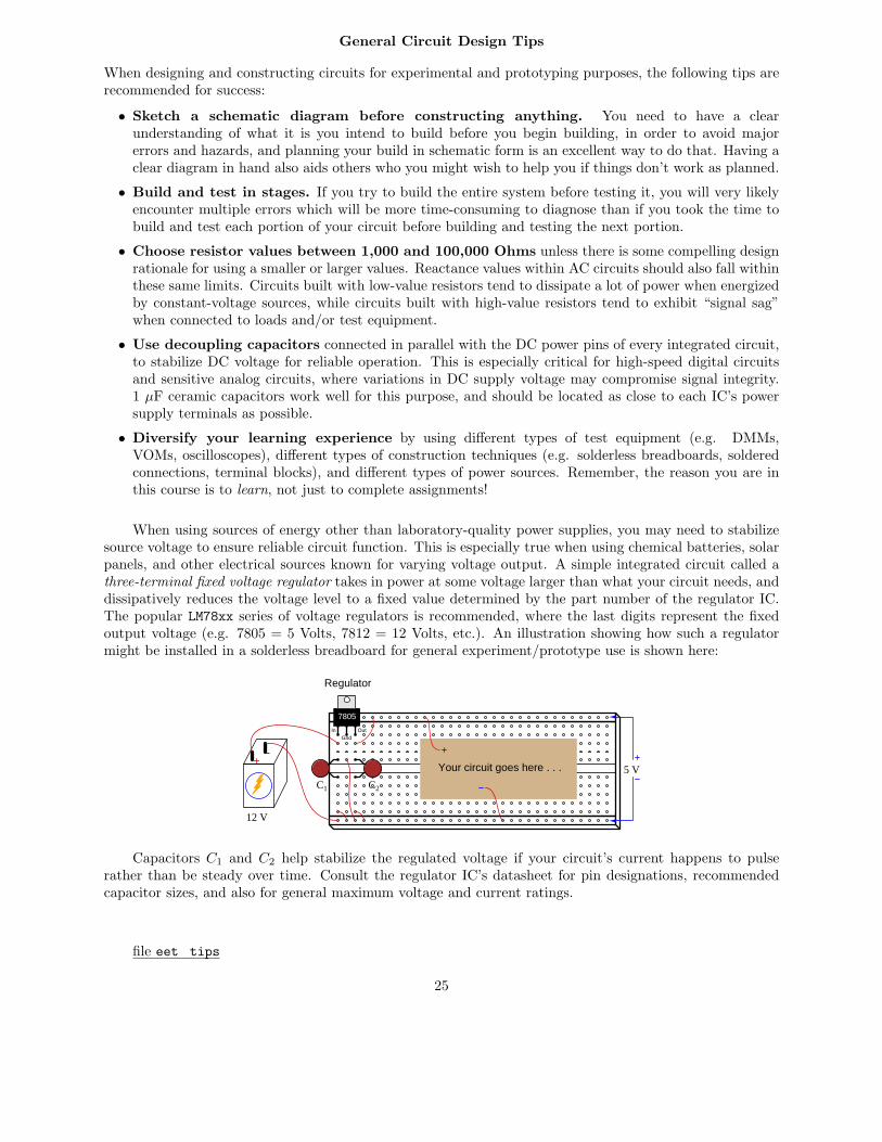
When using sources of energy other than laboratory-quality power supplies, you may need to stabilizesource voltage to ensure reliable circuit function. This is especially true when using chemical batteries, solarpanels, and other electrical sources known for varying voltage output. A simple integrated circuit called athree-terminal fixed voltage regulator takes in power at some voltage larger than what your circuit needs, anddissipatively reduces the voltage level to a fixed value determined by the part number of the regulator IC.The popular LM78xx series of voltage regulators is recommended, where the last digits represent the fixedoutput voltage (e.g. 7805 = 5 Volts, 7812 = 12 Volts, etc.). An illustration showing how such a regulatormight be installed in a solderless breadboard for general experiment/prototype use is shown here:
7805
+-
12 V
5 V
Regulator
C1 C2
InGnd
Out
Your circuit goes here . . .
Capacitors C1 and C2 help stabilize the regulated voltage if your circuit’s current happens to pulserather than be steady over time. Consult the regulator IC’s datasheet for pin designations, recommendedcapacitor sizes, and also for general maximum voltage and current ratings.
file eet_tips
25

General Troubleshooting Advice
All electronic circuit faults fall into at least one of these categories:
• Connection fault – the components are not properly connected together.
• Design flaw – the circuit cannot work because something about it is incorrectly designed.
• Lack of power/signal or poor quality – the power and/or signal source is “dead” or “noisy”
• Component fault – one or more components is faulty.
• Test equipment – either the test equipment itself is faulty, or is not being used appropriately.
Of these categories, the one causing more problems for students initially learning about circuits than allthe others is the first: connection fault. This is because the ability to translate an idea and/or a schematicdiagram into a physical circuit is a skill requiring time to develop. Many such problems may be avoided by(1) drawing a complete schematic of what you intend to build before you build it, (2) marking that schematicto show which connections have been made and which are left to make, and (3) using an ohmmeter (notyour eyes!) to verify that every pair of points which should be connected are connected and that no pointswhich should be electrically distinct from each other are in fact electrically common.
Troubleshooting strategies
• Verify the symptom(s) – Always check to see that the symptom(s) match what you’ve been told byothers. Even if the symptoms were correctly reported, you may notice additional (unreported) symptomshelpful in identifying the fault.
• Verify good power quality – Is the source voltage within specifications, and relatively free of “ripple”and other noise?
• Check signals at component terminals – Use an oscilloscope or multimeter to check for propersignals at each of the component pins, to see if each one matches your expectations. An importantcheck, especially for integrated circuits, is whether the measured output signal(s) are appropriate forthe measured input signal(s).
• Simply the system – If possible, re-configure the circuit to be as simple as possible, because complexitymakes faults harder to find.
• Swap identical components – If particular a component is suspected of being faulty, and you areable to swap another (identical) component for it, do so to see whether or not the problem moves withthe old component. If so, that component is to blame; if not, the problem lies elsewhere.
• Always look for Root Cause(s) – don’t declare success simply by finding the proximate (i.e. themost direct) cause, but continue your search to find what design flaw, circumstance, or other distalcause led to it.
file eet_troubleshooting
26