Embed Size (px)
Citation preview
Instruction manual
Address: Phone: + 41 44 776 33 66
Im Grindel 6 Fax: + 41 44 776 33 65
CH-8932 Mettmenstetten E-Mail: [email protected]
Switzerland Internet: www.tablestable.com
ACTIVE VIBRATION ISOLATION
Im Grindel 6 Phone : +41 44 776 33 66 CH-8932 Mettmenstetten Fax: +41 44 776 33 65 Switzerland E-Mail: [email protected]
2
Table of Contents
Notes on Equipment Safety ........................................................................................................ 3
Safety Instructions ...................................................................................................................... 3
Cleaning the outside of the System ............................................................................................ 3
Accessories ................................................................................................................................ 4
General ...................................................................................................................................... 4
Optimum Support Surface .......................................................................................................... 6
Test of Support Surface ............................................................................................................. 6
First Time Installation ................................................................................................................. 6
Auto-Levelling ............................................................................................................................ 6
Adjustable Foot .......................................................................................................................... 7
Operation ................................................................................................................................... 7
Display Overview ....................................................................................................................... 8
Observing Mode ......................................................................................................................... 9
Function Menu ........................................................................................................................... 9
Locking System for Transport................................................................................................... 10
Isolation Mode .......................................................................................................................... 10
BNC Output Jack ..................................................................................................................... 10
Remote Output ......................................................................................................................... 10
Specifications TS-150 LP and TS-140 LP ................................................................................ 11
Transmissibility ......................................................................................................................... 12
Sales Offices ............................................................................................................................ 13
Service Order ........................................................................................................................... 14
Im Grindel 6 Phone : +41 44 776 33 66 CH-8932 Mettmenstetten Fax: +41 44 776 33 65 Switzerland E-Mail: [email protected]
3
Notes on Equipment Safety The vibration isolation systems TS-150 LP and TS-140 LP have been designed, manu-
factured and tested to conform to the safety regulations for measurement- and control-equipment DIN EN 61010-1:2001 (IEC 61010-1 second edition 2001-02) and satisfy the relevant requirements of EEC Directive 73/23. The systems conform to EEC Directive 89/336 (electro-magnetic compatibility). The operator should read this manual which contains important warnings and information.
Safety Instructions The system may only be plugged into a socket with separate ground. Do not disconnect
this ground, either at the socket, or by using an ungrounded extension cable. Before switching on this apparatus make sure that it is connected to the correct mains
voltage. Do not remove any cover or allow any metal objects to enter any openings in the unit.
Disconnect from mains before removing any covers. Refer servicing to qualified personnel.
Do not use in potentially explosive surroundings.
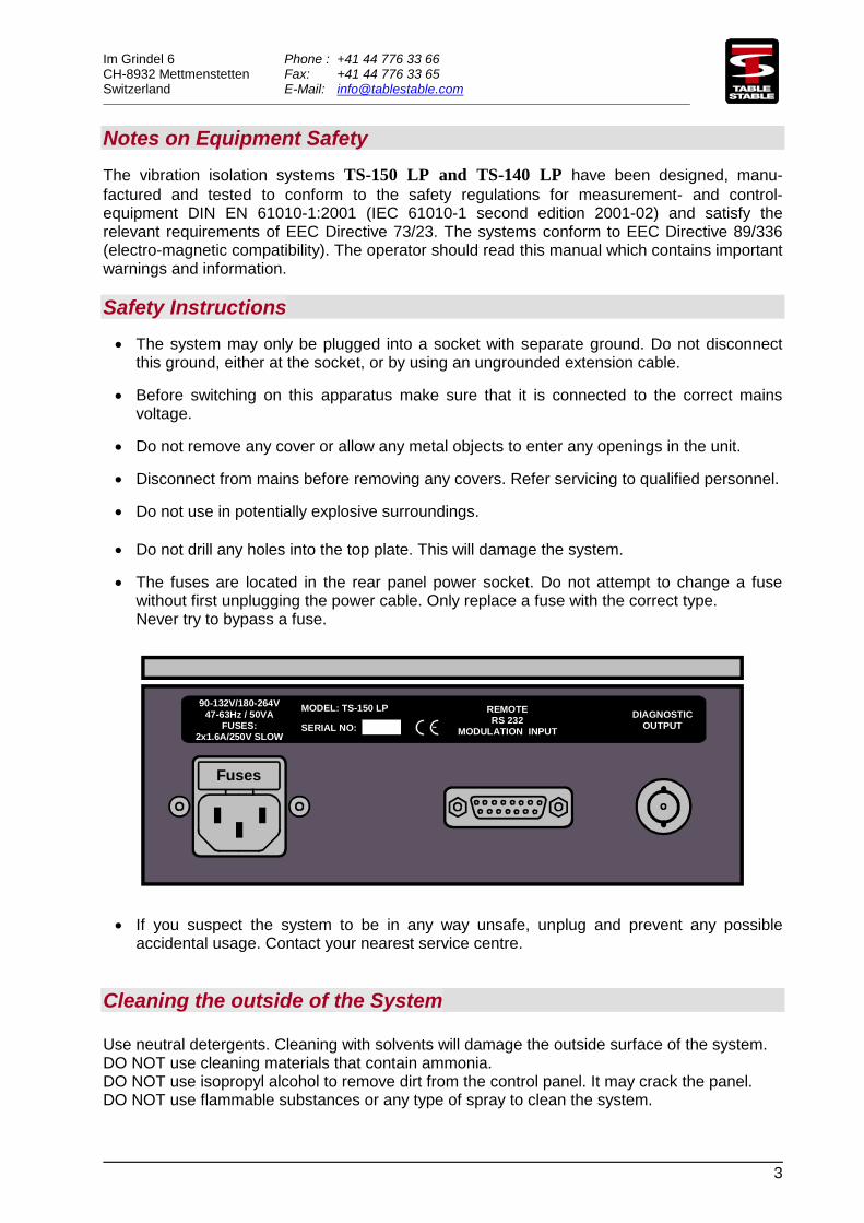
Do not drill any holes into the top plate. This will damage the system. The fuses are located in the rear panel power socket. Do not attempt to change a fuse
without first unplugging the power cable. Only replace a fuse with the correct type. Never try to bypass a fuse.
MODEL: TS-150 LP
SERIAL NO:
90-132V/180-264V
47-63Hz / 50VAFUSES:
2x1.6A/250V SLOW
REMOTERS 232
MODULATION INPUT
DIAGNOSTICOUTPUT
Fuses
If you suspect the system to be in any way unsafe, unplug and prevent any possible accidental usage. Contact your nearest service centre.
Cleaning the outside of the System Use neutral detergents. Cleaning with solvents will damage the outside surface of the system. DO NOT use cleaning materials that contain ammonia. DO NOT use isopropyl alcohol to remove dirt from the control panel. It may crack the panel. DO NOT use flammable substances or any type of spray to clean the system.

Im Grindel 6 Phone : +41 44 776 33 66 CH-8932 Mettmenstetten Fax: +41 44 776 33 65 Switzerland E-Mail: [email protected]
4
Accessories 1 Power Cable 1 Manual 1 Remote Control Box (optional)
General
The TS-150 LP and TS-140 LP are compact dynamic antivibration systems, which offer
isolation against all six translational and rotational vibration modes. These moderately priced dynamic vibration isolation systems achieve in a very small volume better isolation than is possible with the biggest and most expensive passive systems. Inertial feedback using piezoelectric force motors provides not only isolation from building vibrations, but also isolation from vibration sources placed on the system itself. This means, for example, that a delicate microscope isolated by the system will remain at rest despite forces being applied via the operator's hands. The inherent stiffness of the systems, some 200 - 500 times greater than that of a 1 Hz resonance passive isolator, imparts excellent directional and positional stability. The characteristics of an active isolation system are typified by the virtual lack of any low frequency resonance, a resonance which plagues all passive isolation systems. The TS-150 LP is a complete active isolation system measuring 450 x 400 x 78,5 mm and
which can support a maximum load of 150kg. The TS-140 LP measures 500 x 600 x 84 mm,
can support a maximum load of 140kg, but has otherwise identical properties. The systems have been designed to offer excellent isolation even at frequencies as low as 2-3Hz, where many buildings show large horizontal amplitudes due to oscillation about the vertical axis. Isolation begins at about 0.7 Hz, increasing rapidly to at least 40dB beyond about10 Hz. These systems are extremely convenient to use. Load compensation (auto-levelling) is performed automatically on switching on the power. If the load is changed whilst the system is isolating, it automatically readjusts and then returns to the isolation mode. Furthermore, at the push of a button the system locks itself for shipping. Apart from a single adjustable foot to allow for unevenness in the support surface, there are no manual adjustments to be made. All the control circuitry, including the power supply, is built into the unit. Power consumption is less than 10 W. The unit has a universal input and may be connected to any AC power point from 90 to 120VAC, or 200 to 240VAC The design has been optimized to achieve best possible isolation for delicate instruments such as the Scanning Probe Microscopes (AFM, STM), Scanning Electron Microscopes, Interferometers and other high resolution instruments, allowing the ultimate performance to be achieved from these instruments. The tables have also proved to be extremely successful for supporting sensitive experiments, such as patch clamp, micro injection or the troughs for liquids used in measurements on Langmuir-Blodgett films.
Im Grindel 6 Phone : +41 44 776 33 66 CH-8932 Mettmenstetten Fax: +41 44 776 33 65 Switzerland E-Mail: [email protected]
5
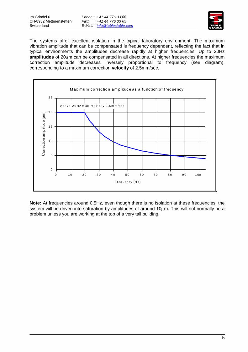
The systems offer excellent isolation in the typical laboratory environment. The maximum vibration amplitude that can be compensated is frequency dependent, reflecting the fact that in typical environments the amplitudes decrease rapidly at higher frequencies. Up to 20Hz
amplitudes of 20m can be compensated in all directions. At higher frequencies the maximum correction amplitude decreases inversely proportional to frequency (see diagram),
corresponding to a maximum correction velocity of 2.5mm/sec.
3 0 4 0 5 0 6 0 7 0 8 0 1 00
5
0
1 0
2 5
Corr
ectio
n a
mp
litu
de [
µm
]
Fr eq ue ncy [H z]
0 2 0
A bo ve 2 0 H z m ax . v e lo c ity 2 .5 m m /sec
M ax im um co rrection am p litude as a funct ion o f f requency
2 0
1 5
1 0
9 0
Note: At frequencies around 0.5Hz, even though there is no isolation at these frequencies, the
system will be driven into saturation by amplitudes of around 10m. This will not normally be a problem unless you are working at the top of a very tall building.
Im Grindel 6 Phone : +41 44 776 33 66 CH-8932 Mettmenstetten Fax: +41 44 776 33 65 Switzerland E-Mail: [email protected]
6
Optimum Support Surface To obtain the optimum performance from the system it must be supported on a surface which is as rigid as possible. The best possible performance is obtained with the system sitting directly on the floor. However for most applications this will not be practical, and some support structure will be required to bring the system to a convenient operating height. Most simple table structures will be rigid enough vertically, but will leave much to be desired horizontally. The addition of diagonal struts between the table legs can improve the situation dramatically. It is good to bear in mind that any support structure will follow the building vibrations exactly up to some certain cut off frequency at which point the structure goes into resonance and amplifies the vibration amplitudes. A typical structure may have its lowest horizontal resonance frequencies around 40-60 Hz. It is an unfortunate fact of life that the amplitudes of the vertical vibrations of the building (dominantly bending modes of the floor) are largest in the centre of the floor, where for convenience most experiments are situated! Since the system is quite small, a possible location may be on a shelf attached to a building pillar. Good braces will be required to support the shelf. This location has the advantage that the vertical vibrations of the building will be very much reduced.
Test of Support Surface Although the systems will operate on virtually any support surface, a soft support structure resonantly amplifies certain building vibration frequencies and these will therefore be less effectively isolated. You can obtain an idea for the suitability of your support structure by observing the diagnostic signal while pushing on the support. The isolation should be disabled for this test. If the support is rigid the signals should hardly respond to a push on the support in any direction. Now try tapping the support to excite its internal resonances. Generally the support will react more strongly to a horizontal tap than to a vertical one. A very resonant support will show long lived resonances and the isolation will be seriously affected at these frequencies. A better support will show well damped resonances.
First Time Installation For shipping the system has been locked to prevent damage. It will automatically be unlocked when power is applied to the system. Sometimes equipment can get very cold during shipping. We recommend that if the system is cold you allow 2-3 hours for it to reach room temperature before connecting the power, otherwise a malfunction may arise due to condensation.
Auto-Levelling When operating the system for the first time, place on a suitable rigid support surface and switch on the power. If the system has been locked for transport the motors will run rapidly for a few seconds until the system is floating.
Im Grindel 6 Phone : +41 44 776 33 66 CH-8932 Mettmenstetten Fax: +41 44 776 33 65 Switzerland E-Mail: [email protected]
7
Adjustable Foot
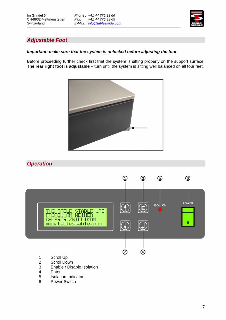
Important: make sure that the system is unlocked before adjusting the foot Before proceeding further check first that the system is sitting properly on the support surface.
The rear right foot is adjustable – turn until the system is sitting well balanced on all four feet.
Operation 1 Scroll Up
2 Scroll Down 3 Enable / Disable Isolation
4 Enter 5 Isolation Indicator 6 Power Switch
EPOWER
ISOL. ON
0
1 3 5 6
42
Im Grindel 6 Phone : +41 44 776 33 66 CH-8932 Mettmenstetten Fax: +41 44 776 33 65 Switzerland E-Mail: [email protected]
8
Display Overview
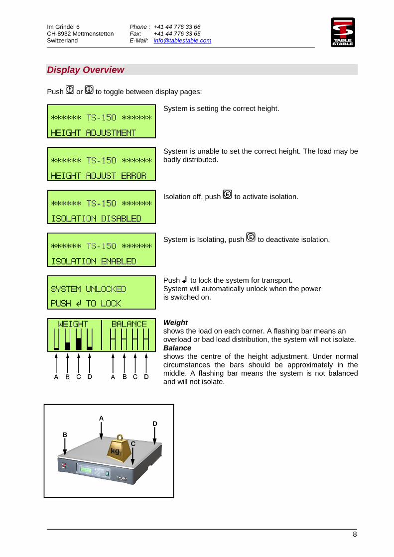
Push or to toggle between display pages:
System is setting the correct height.
System is unable to set the correct height. The load may be badly distributed.
Isolation off, push E to activate isolation.
System is Isolating, push E to deactivate isolation.
Push to lock the system for transport. System will automatically unlock when the power is switched on.
Weight shows the load on each corner. A flashing bar means an overload or bad load distribution, the system will not isolate.
Balance shows the centre of the height adjustment. Under normal circumstances the bars should be approximately in the middle. A flashing bar means the system is not balanced and will not isolate.
A
B
C
D
Im Grindel 6 Phone : +41 44 776 33 66 CH-8932 Mettmenstetten Fax: +41 44 776 33 65 Switzerland E-Mail: [email protected]
9
Time Base N (0-4)
Observing Mode
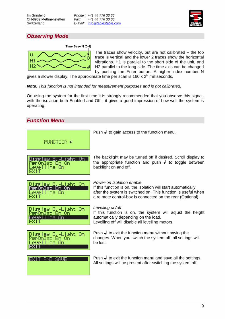
The traces show velocity, but are not calibrated – the top trace is vertical and the lower 2 traces show the horizontal vibrations. H1 is parallel to the short side of the unit, and H2 parallel to the long side. The time axis can be changed by pushing the Enter button. A higher index number N
gives a slower display. The approximate time per scan is 160 x 2N milliseconds.
Note: This function is not intended for measurement purposes and is not calibrated. On using the system for the first time it is strongly recommended that you observe this signal, with the isolation both Enabled and Off - it gives a good impression of how well the system is operating.
Function Menu
Push to gain access to the function menu.
The backlight may be turned off if desired. Scroll display to
the appropriate function and push to toggle between backlight on and off.
Power-on Isolation enable If this function is on, the isolation will start automatically after the system is switched on. This function is useful when a re mote control-box is connected on the rear (Optional).
Levelling on/off If this function is on, the system will adjust the height automatically depending on the load. Levelling off will disable all levelling motors.
Push to exit the function menu without saving the changes. When you switch the system off, all settings will be lost.
Push to exit the function menu and save all the settings. All settings will be present after switching the system off.
Im Grindel 6 Phone : +41 44 776 33 66 CH-8932 Mettmenstetten Fax: +41 44 776 33 65 Switzerland E-Mail: [email protected]
10
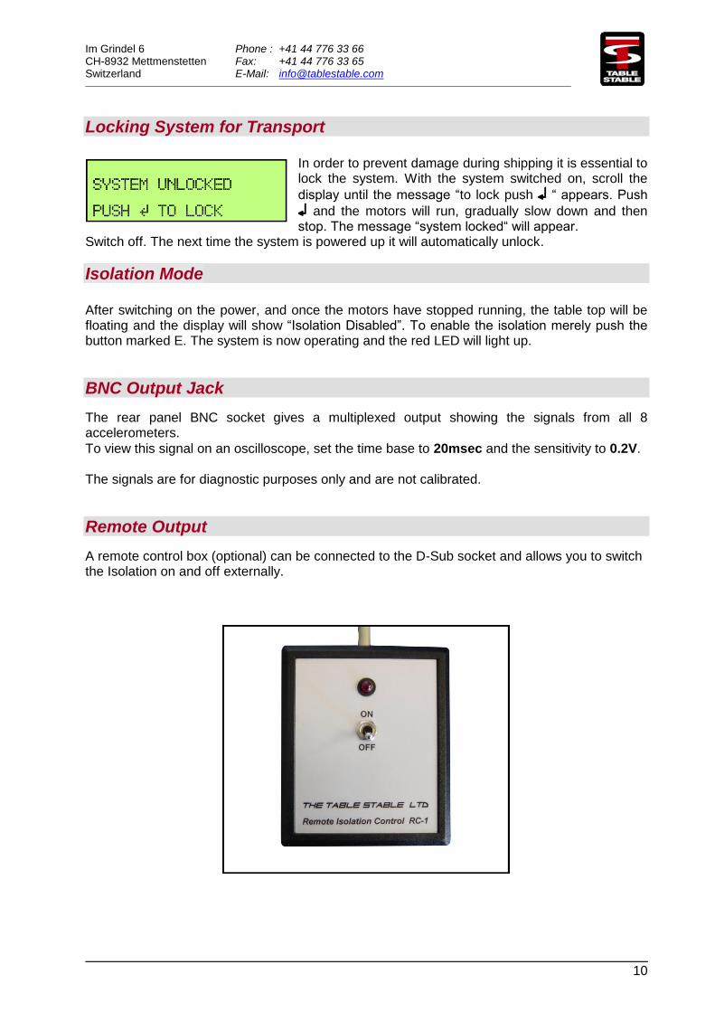
Locking System for Transport
In order to prevent damage during shipping it is essential to lock the system. With the system switched on, scroll the
display until the message “to lock push “ appears. Push
and the motors will run, gradually slow down and then stop. The message “system locked“ will appear.
Switch off. The next time the system is powered up it will automatically unlock.
Isolation Mode After switching on the power, and once the motors have stopped running, the table top will be floating and the display will show “Isolation Disabled”. To enable the isolation merely push the button marked E. The system is now operating and the red LED will light up.
BNC Output Jack The rear panel BNC socket gives a multiplexed output showing the signals from all 8 accelerometers.
To view this signal on an oscilloscope, set the time base to 20msec and the sensitivity to 0.2V. The signals are for diagnostic purposes only and are not calibrated.
Remote Output A remote control box (optional) can be connected to the D-Sub socket and allows you to switch the Isolation on and off externally.
Im Grindel 6 Phone : +41 44 776 33 66 CH-8932 Mettmenstetten Fax: +41 44 776 33 65 Switzerland E-Mail: [email protected]
11
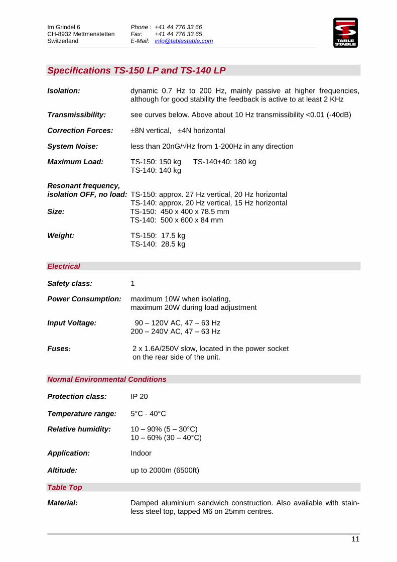
Specifications TS-150 LP and TS-140 LP
Isolation: dynamic 0.7 Hz to 200 Hz, mainly passive at higher frequencies, although for good stability the feedback is active to at least 2 KHz
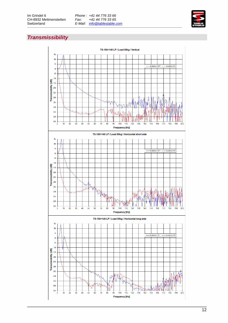
Transmissibility: see curves below. Above about 10 Hz transmissibility <0.01 (-40dB)
Correction Forces: 8N vertical, 4N horizontal
System Noise: less than 20nG/Hz from 1-200Hz in any direction
Maximum Load: TS-150: 150 kg TS-140+40: 180 kg TS-140: 140 kg
Resonant frequency,
isolation OFF, no load: TS-150: approx. 27 Hz vertical, 20 Hz horizontal TS-140: approx. 20 Hz vertical, 15 Hz horizontal
Size: TS-150: 450 x 400 x 78.5 mm TS-140: 500 x 600 x 84 mm
Weight: TS-150: 17.5 kg TS-140: 28.5 kg
Electrical
Safety class: 1
Power Consumption: maximum 10W when isolating, maximum 20W during load adjustment
Input Voltage: 90 – 120V AC, 47 – 63 Hz 200 – 240V AC, 47 – 63 Hz
Fuses: 2 x 1.6A/250V slow, located in the power socket on the rear side of the unit.
Normal Environmental Conditions
Protection class: IP 20
Temperature range: 5°C - 40°C
Relative humidity: 10 – 90% (5 – 30°C) 10 – 60% (30 – 40°C)
Application: Indoor
Altitude: up to 2000m (6500ft)
Table Top
Material: Damped aluminium sandwich construction. Also available with stain-less steel top, tapped M6 on 25mm centres.
Im Grindel 6 Phone : +41 44 776 33 66 CH-8932 Mettmenstetten Fax: +41 44 776 33 65 Switzerland E-Mail: [email protected]
12
Transmissibility
Im Grindel 6 Phone : +41 44 776 33 66 CH-8932 Mettmenstetten Fax: +41 44 776 33 65 Switzerland E-Mail: [email protected]
13
Sales Offices
Geographical Europe,
near and middle East,
Africa, India:
Derendingerstrasse 40, 72072 Tübingen
Germany Phone: +49-7071-54-99 863 Fax: +49-7071-54-98-821
e-mail: [email protected] Internet: www.hwlscientific.com
Americas, Australia,
New Zealand:
23042 Alcalde Drive, Suite E
Laguna Hills, Ca 92653
USA Phone: 949-363-2905 Fax: 949-340-9751
e-mail: [email protected] Internet: www.herzan.com
Asia:
18/F, Yokohama Creation
Square Bldg.,5-1, Sakaecho, Kanagawa-Ku
Yokohama Kanagawa 221-0052
Japan Phone: +81-45-450-2211 FAX: +81-45-450-2221
e-mail: [email protected] Internet: www.herz-f.co.jp
ASEAN countries and China
(including Hong Kong)
83 Bukit Drive, #05-07
Singapore 587849 Phone: +65 96181 268
e-mail: [email protected] Internet: www.octalab.com
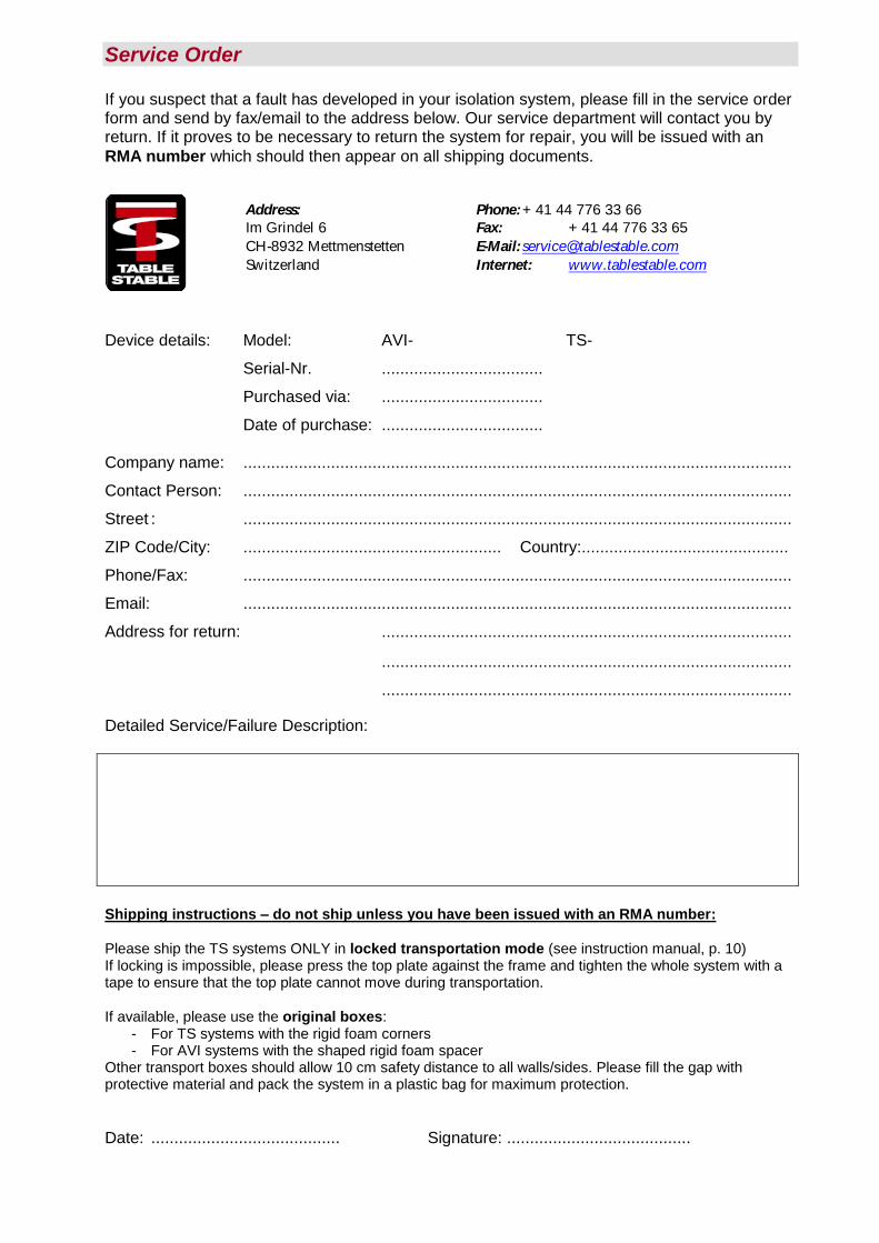
Service Order If you suspect that a fault has developed in your isolation system, please fill in the service order form and send by fax/email to the address below. Our service department will contact you by return. If it proves to be necessary to return the system for repair, you will be issued with an
RMA number which should then appear on all shipping documents.
Address: Phone: + 41 44 776 33 66
Im Grindel 6 Fax: + 41 44 776 33 65
CH-8932 Mettmenstetten E-Mail: [email protected]
Switzerland Internet: www.tablestable.com
Device details: Model: AVI- TS- Serial-Nr. ................................... Purchased via: ................................... Date of purchase: ................................... Company name: ....................................................................................................................... Contact Person: ....................................................................................................................... Street : ....................................................................................................................... ZIP Code/City: ........................................................ Country:............................................. Phone/Fax: ....................................................................................................................... Email: ....................................................................................................................... Address for return: ......................................................................................... ......................................................................................... ......................................................................................... Detailed Service/Failure Description:
Shipping instructions – do not ship unless you have been issued with an RMA number:
Please ship the TS systems ONLY in locked transportation mode (see instruction manual, p. 10) If locking is impossible, please press the top plate against the frame and tighten the whole system with a tape to ensure that the top plate cannot move during transportation.
If available, please use the original boxes: - For TS systems with the rigid foam corners - For AVI systems with the shaped rigid foam spacer
Other transport boxes should allow 10 cm safety distance to all walls/sides. Please fill the gap with protective material and pack the system in a plastic bag for maximum protection.
Date: ......................................... Signature: ........................................


![Ii-Key/HER-2/neu(776–790) hybrid peptides induce more eVective … · 2020. 3. 19. · tant HER-2/neu(776–790) MHC class II epitope [16, 41, 44, 46] in a novel strategy to enhance](https://img.pdfslide.us/doc/110x75/613c46a54c23507cb635472d/ii-keyher-2neu776a790-hybrid-peptides-induce-more-evective-2020-3-19.jpg)