Embed Size (px)
Citation preview
2005 USENIX Annual Technical Conference USENIX Association 135
Active Internet Traffic Filtering:Real-Time Response to Denial-of-Service Attacks
Katerina Argyraki David R. CheritonDistributed Systems Group
Stanford University{argyraki, cheriton}@dsg.stanford.edu
Abstract
This paper describes Active Internet Traffic Filtering(AITF), a mechanism for blocking highly distributeddenial-of-service (DDoS) attacks. These attacks are anacute contemporary problem, with few practical solu-tions available today; we describe in this paper the rea-sons why no effective DDoS filtering mechanism hasbeen deployed yet. We show that the current Internet’srouters have sufficient filtering resources to thwart suchattacks, with the condition that attack traffic be blockedclose to its sources; AITF leverages this observation. Ourresults demonstrate that AITF can block a million-flowattack within seconds, while it requires only tens of thou-sands of wire-speed filters per participating router — anamount easily accommodated by today’s routers. AITFcan be deployed incrementally and yields benefits evento the very first adopters.
1 IntroductionWe have recently witnessed a dramatic increase in thefrequency and ferocity of distributed denial-of-service(DDoS) attacks. In December 2003, an attack keptSCO’s web site practically unreachable for more thana day [6]; in June 2004, another attack flooded Aka-mai’s name servers, disrupting access to its clients for2 hours, including the Google and Yahoo search en-gines [7]; a month later, an attack flooded DoubleClick’sname servers, disabling ad distribution to its 900 clientsfor 3 hours [8]. Considering that network downtime costshundreds of thousands of dollars per hour [19], such inci-dents can translate into millions of dollars of lost revenuefor the victim. Yet, the DDoS problem remains unsolved.
We recognize three (not all of them orthogonal) prob-lems that render DDoS traffic hard to filter:
Source address spoofing: An attack source often usesmultiple fake source IP addresses to send its traffic. Asa result, the victim can neither identify the attack sourcenor specify a filtering rule (e.g., “block all traffic with
source IP address S”) that selectively blocks its traffic.
Large number of attack sources: Each hardware routerhas only a limited number of filters that can block traf-fic without degrading the router’s performance (i.e., fil-ters operating at wire speed). The limitation comes fromcost and space. Wire-speed filters are typically stored inexpensive TCAM (Ternary Content Addressable Mem-ory), which they share with the router’s forwarding table.Some of the largest TCAM chips available today accom-modate 256K entries [4]. A sophisticated router linecardfits at most 1 TCAM chip [1], i.e., tens of thousands offilters per network interface. On the other hand, a large-scale attack can involve millions of attack sources [22].So, even if source address spoofing were completelyeliminated, i.e., even if the victim could identify each at-tack source and specify a filtering rule for it, the victim’sfirewall would not have enough filters to accommodateall the rules.
The straightforward solution to such a resource prob-lem is aggregation: Don’t install a separate filter for eachattack source; instead, identify the IP prefixes that covermost attack sources and block all traffic from these pre-fixes. Unfortunately, filter aggregation does not workin most DDoS scenarios: Attack sources are typicallyworm-infected populations, highly distributed across theInternet. As a result, blocking the prefixes that corre-spond to the attack sources results in blocking most In-ternet prefixes, thereby causing severe collateral damage.
Pushing filtering into the Internet core does not scale:If the victim’s firewall cannot block attack traffic by it-self, the straightforward solution is to push filtering ofattack traffic back into the Internet core: Identify the up-stream peering networks that forward attack traffic andsend them appropriate filtering requests. Unfortunately,this approach does not scale, because it introduces end-to-end filtering state into core routers. Consider a corerouter receiving filtering requests from 10 victims; eachvictim is under attack by a million sources. The corerouter can either block traffic from each attack sourceto each victim, or aggregate filtering rules and rate-limit
2005 USENIX Annual Technical Conference USENIX Association136
all traffic going to the victims. The former requires 10million filters; the latter requires only 10 filters, but sac-rifices most good traffic going to the victims.
Yet, there are enough filtering resources in the Inter-net to block such large-scale attacks. An attack comingfrom thousands of different networks involves thousandsof routers; assuming each router contributes a few thou-sand filters, there are millions of filters available to blockattack traffic. And the closer we get to the attack sources,the larger the amount of filtering resources available perattack source — it is the victim’s firewall and the Inter-net core that are the “filtering bottleneck”. Unfortunately,today, the victim has no access to these resources, sincethere is no way for a DDoS victim to identify routers lo-cated close to the attack sources and make them blockattack traffic.
In this paper, we present a DDoS filtering mecha-nism that overcomes these problems. Our source addressspoofing solution is a hardware-friendly variant of theIP route record (RR) technique [20]. Although differ-ent from traditional packet marking techniques [21, 14](which do not provide an explicit recorded route in eachpacket), our RR approach is not a radical departure fromthem, either. Our main contribution is Active Inter-net Traffic Filtering (AITF), a protocol that leveragesrecorded route information to block attack traffic.
An AITF-enabled receiver uses the routes recorded onincoming packets to identify the last point of trust oneach attack path and causes attack traffic to be blockedat that point, i.e., as close as possible to its sources.We provide a way to do this securely — AITF preventsabuse by malicious nodes seeking to disrupt other nodes’communications. We show that our approach can selec-tively block a million attack sources, yet requires onlytens of thousands of TCAM memory entries and a fewmegabytes of DRAM memory from each participatingrouter; these numbers correspond to the specifications ofreal products [4, 1]. We also provide an incremental de-ployment scenario, in which even early adopters receivea concrete benefit; this benefit is compounded by furtherdeployment.
The rest of the paper is organized as follows: Section2 describes route record and how a receiver can use itto identify distinct traffic flows. Section 3 describes theAITF protocol in detail, naively assuming that no sourceaddress spoofing occurs. We remove this assumptionin Section 4, where we describe how AITF deals withspoofing attacks. We estimate AITF performance in Sec-tion 5 and verify our estimates through simulation in Sec-tion 6. Section 7 analyzes deployment issues, Section 8discusses additional attacks and potential defenses, andSection 9 presents related work. Section 10 concludesthe paper.
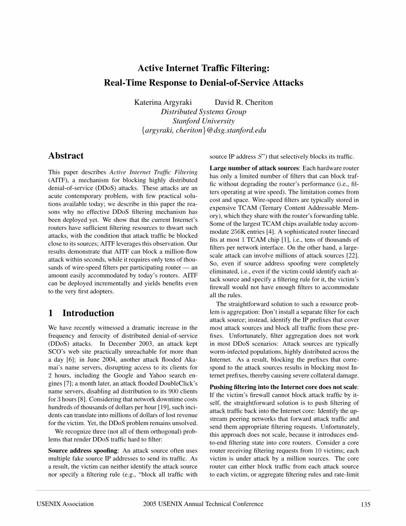
2 Limiting spoofing2.1 Route RecordA router that participates in a route record (RR) schemewrites its IP address on each packet it forwards. In ourapproach, only border routers participate in RR. As a re-sult, each packet carries the identities of a sub-list of theborder routers that forwarded it. For example, in Figure1, border routers Agw , X , Y , and Vgw are RR-enabled;each packet sent by host A to host V carries recordedroute {Agw X Y Vgw} upon reaching its destination.
Figure 1: Packets sent by host A to host V carry recordedroute {Agw X Y Vgw}.
We implement RR functionality as a “shim” protocolbetween the IP and transport layers, i.e, the RR header isintroduced as the beginning of the IP payload. We chosenot to use the traditional IP RR option, because of itsperformance overhead — traditional IP RR packets aretypically handled by routers off the fast path. The detailsof how each participating router adds its address to theRR header are described in the Appendix, Section A.1.
When a packet crosses an RR-enabled, “non-malicious” Internet area adjacent to its destination do-main, its recorded route includes an authentic (non-spoofed) suffix. Specifically, the last n components ofthe recorded route are authentic, when the last n borderrouters crossed by the packet are RR-enabled, and thereis no malicious node on the path that interconnects them.As we explain next, this enables a receiver to identify dis-tinct incoming traffic flows in the face of source addressspoofing.
2.2 Identifying Distinct FlowsWe define the recorded path of a packet as the sequenceof IP addresses that correspond to: the packet’s source,the list of border routers specified in the RR header, andthe packet’s destination. We define a flow as the setof all packets that share a common recorded path suf-fix. For example, in Figure 1, all packets with path{A Agw X Y Vgw V } constitute a distinct flow; all pack-ets with path {∗ Agw X Y Vgw V } also constitute a dis-
2005 USENIX Annual Technical Conference USENIX Association 137
tinct (aggregate) flow. We use F{P} to refer to flow F
with recorded path P .A DDoS victim feeds recorded paths into a local pol-
icy module, which classifies incoming traffic in distinctflows, decides which ones are undesired and forms filter-ing requests against them. The operation of the policymodule depends on the specific service run by the victimand is outside the scope of this paper. We call it a “pol-icy module”, because it determines a “defense policy”,i.e, which flows must be blocked. AITF (described in thenext section) is the mechanism that enforces the chosenpolicy.
It is up to the policy module to classify incoming traf-fic in multiple “flow levels”, in order to identify unde-sired flows in the face of source address and path spoof-ing. For example, consider that in Figure 1 attack sourceA is sending high-rate traffic to victim V . If networkANET prevents source address spoofing, V can easilyidentify F1{A Agw X Y Vgw V } as a high-rate flow and,thus, undesired. If A is able to spoof multiple source IPaddresses, V can only identify F2{∗ Agw X Y Vgw V }as the undesired flow.
Once the policy module identifies an undesired flow, itsends a filtering request to the local AITF process. AITFdoes not assume that the recorded path of an undesiredflow coincides with its real path. I.e., if the policy moduleidentifies F{∗ Agw X Y Vgw V } as an undesired flow,this only means that the victim does not want to receiveany more packets with this recorded path; it does not nec-essarily mean that these packets are indeed forwarded byAgw , X , and Y .
3 Basic AITF ProtocolWe start with an overview of the protocol (Section 3.1)and terminology (Section 3.2); we describe our algo-rithm incrementally, through Sections 3.3, 3.4, 3.5, and3.6; we discuss appropriate values for its parameters inSection 3.7. To simplify description, we naively assumethat no source address/path spoofing occurs — we re-move this assumption in the next section.
3.1 OverviewUpon identifying an undesired flow, the victim sends afiltering request to its gateway (Vgw in Figure 1). Thevictim’s gateway temporarily blocks the undesired flowand identifies the border router located closest to the at-tack source(s) — call it the attack gateway (Agw in Fig-ure 1). Then, the victim’s gateway initiates a “counter-connection” setup with the attack gateway, i.e., an agree-ment not to transmit certain packets — the opposite ofa TCP connection setup, which is an agreement to ex-change packets. As soon as the counter-connection setup
is completed, the victim’s gateway can remove its tem-porary filter. If the attack gateway does not cooperate,the victim’s gateway can escalate the filtering request tothe next border router closest to the attack gateway (Xin Figure 1). Escalation can continue recursively untila router along the attack path responds and a counter-connection setup is completed. If no router responds,attack traffic is blocked locally by the victim’s gateway.However, as we will see, AITF both assists and motivatesrouters close to the attack source(s) to help block attacktraffic.
3.2 TerminologyThe recorded path P of an undesired flow has form{A Agw ... Vgw V }, where
• A is the “attack source”, i.e., the node thought to begenerating the undesired traffic; if A = ∗, all trafficthrough Agw is undesired.
• Agw is the “attack gateway”, i.e., the border routerthought to be closest to A.
• Vgw is the “victim’s gateway”, i.e., the border routerclosest to the victim.
• V is the victim.
We assume that the only node affected by the attackis V ; e.g., if this is a flooding attack, the only part ofthe network that is congested is the tail-circuit from Vgw
to V . If Vgw were also affected, it itself would be the“victim”, and its closest upstream border router wouldbe the “victim’s gateway”.
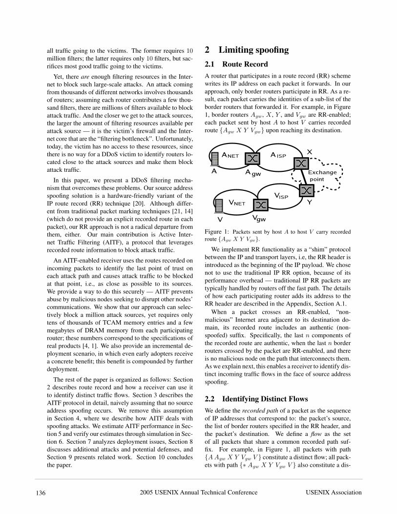
3.3 Blocking Close to the Attack SourceAs shown in Figure 2, AITF involves 4 entities:
1. The victim V sends a filtering request to Vgw , spec-ifying an undesired flow F .
2. The victim’s gateway Vgw :
(a) Installs a temporary filter to block F for Ttmp
seconds.
(b) Initiates a 3-way handshake with Agw .
(c) Removes its temporary filter, upon completionof the handshake.
3. The attack gateway Agw :
(a) Responds to the 3-way handshake.
(b) Installs a temporary filter to block F for Ttmp
seconds, upon completion of the handshake.
(c) Sends a filtering request to the attack sourceA, to stop F for Tlong � Ttmp minutes.
2005 USENIX Annual Technical Conference USENIX Association138
(d) Removes its temporary filter, if A complieswithin Ttmp seconds; otherwise, it discon-nects A.
4. The attack source A stops F for Tlong minutes orrisks disconnection.
All filtering requests are rate limited. I.e., the victim’sgateway accepts a limited rate of requests from each al-leged victim. Similarly, the attack gateway (i) accepts alimited rate of requests (handshake initializations) fromeach alleged victim gateway and (ii) sends a limited rateof requests to each alleged attack source.
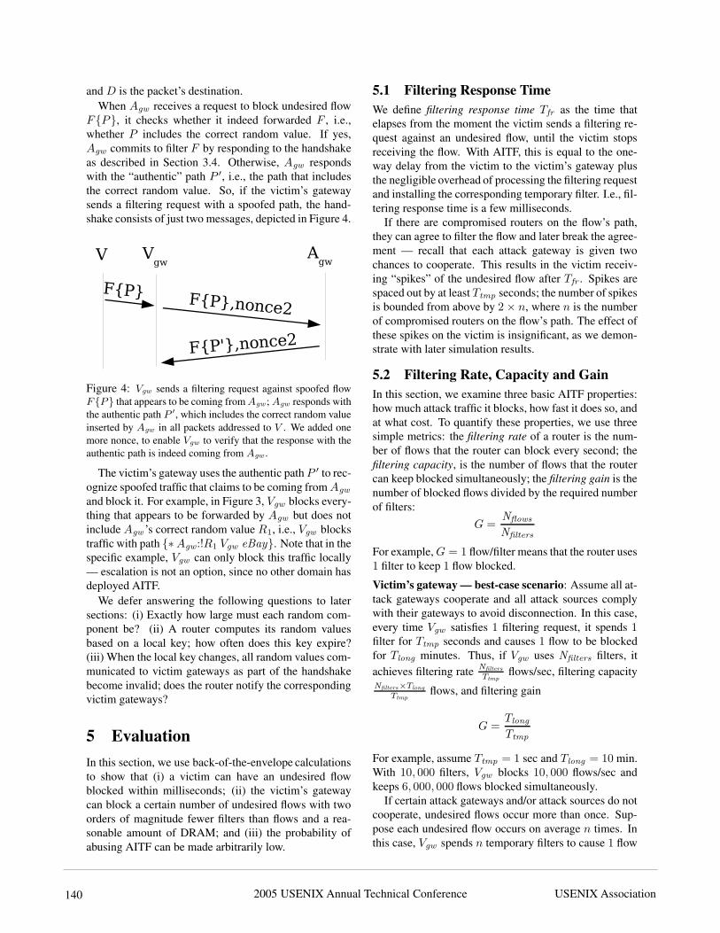
The reason for the temporary filter on the victim’sgateway is to immediately protect the victim until the at-tack gateway takes responsibility. The reason for directlycontacting the attack gateway is to avoid creating a filter-ing bottleneck in the Internet core. Finally, the reason forthe 3-way handshake is to enable the attack gateway toverify that the requester of the filter is indeed on the pathto the alleged victim; the handshake is further explainednext.
3.4 Securing Edge-to-edge CommunicationThe 3-way handshake is depicted in Figure 2: Vgw sendsto Agw a request to block F ; Agw sends to V a messagethat includes F and a nonce; Vgw intercepts the messageand sends it back to Agw .
Figure 2: AITF entities and message exchange.Vgw proves its location on the path to V by intercept-
ing the nonce sent to V . This prevents malicious nodeM , located off the path from Agw to Vgw , from causinga filter to be installed at Agw and block traffic to V . Bypicking a sufficiently large and properly random valuefor the nonce, it can be made arbitrarily difficult for M
to guess it (see Section 5.4).To avoid buffering state on incomplete 3-way hand-
shakes, Agw computes the nonce as follows:
nonce1 = hashkey(F )
where key is a local key and hash is a keyed hash func-tion. To verify the authenticity of a completion message,
Agw just hashes the flow included in the message andcompares the result to the nonce included in the message(similar to the TCP SYN-cookie technique [13]).
3.5 Identifying LiarsWith what we have described so far, there are two entitiesthat can lie: (i) An attack source can pause an undesiredflow (to avoid disconnection) and resume as soon as theattack gateway has removed its temporary filter. (ii) Anattack gateway can pause an undesired flow and resumeas soon as the victim’s gateway has removed its tempo-rary filter. To catch such liars, we introduce the shadowfiltering table.
Every time a gateway removes a temporary filter fromits TCAM, it creates a copy in DRAM that expires afterTlong . This “shadow filter” helps check whether the cor-responding undesired flow is released prematurely (be-fore Tlong ) by its source. For example, suppose attackgateway Agw has already told attack source A to blockF ; now suppose Agw receives a new filtering requestagainst F and installs a new temporary filter; if the newfilter catches F traffic, Agw checks its shadow filteringtable, finds out that a shadow filter for F already exists(i.e., A has already been told to stop once) and discon-nects A.
The victim’s gateway uses the same technique tocheck whether the attack gateway keeps the undesiredflow blocked for Tlong minutes. The only difference isthat the attack gateway has to be caught violating the fil-tering agreement twice to be classified as “lying” — thefirst time could be due to a lying attack source, so theattack gateway is given the benefit of the doubt once.
3.6 Dealing with Non-Cooperative Gate-ways
An attack gateway can deal with a non-cooperative at-tack source by disconnecting it. This is possible becausethe attack gateway is the border router providing Inter-net connectivity to the attack source. The victim’s gate-way can obviously not deal with a non-cooperative attackgateway the same way, since they belong to separate (noteven peering) administrative domains. To address this,we introduce escalation.
An attack gateway is classified as “non-cooperative”,if it does not respond to the handshake or responds,but is caught violating the filtering agreement twice. Inthat case, the victim’s gateway can “escalate” the filter-ing request to the border router that follows the non-cooperative attack gateway on the flow’s path. The newattack gateway is requested to block all traffic from thelast non-cooperative attack gateway to the victim. Forexample, in Figure 1, Vgw first contacts Agw asking it toblock all traffic from A to V . If Agw does not cooperate,
2005 USENIX Annual Technical Conference USENIX Association 139
Vgw can contact X asking it to block all traffic from Agw
to V . Simply said, an attack gateway either cooperatesand blocks traffic from its misbehaving client(s) to thevictim, or risks losing its connectivity to the victim over-all. This is a strong incentive to cooperate, especiallywhen the victim is a popular public-access site like eBayor Amazon.
There are cases in which escalation is good, and casesin which it is bad. E.g., if eBay is losing most of its goodtraffic to a severe flooding attack, it makes sense to blockaccess from non-cooperative attack gateways in order topreserve connectivity to the rest of the world. On theother hand, if eBay wants to get rid of a couple of an-noying AOL clients, it does not make sense to block theentire AOL, even if its gateway does not cooperate. De-ciding whether escalation is a good or a bad idea is theresponsibility of the policy module. The policy modulecommunicates its decision by declaring (or not) an unde-sired flow “escalatable”.
The victim’s gateway escalates a filtering request ifand only if (i) the corresponding flow is escalatable and(ii) local filter utilization has exceeded a pre-configuredthreshold. Otherwise, the undesired flow is blocked lo-cally for Tlong minutes.
A smart attack source can introduce multiple fakecomponents in the beginning of the RR header and makethe victim’s gateway escalate multiple times (as manyas the fake components), before it actually contacts anauthentic border router. To avoid such abuse, a DDoSvictim can simply ignore the first components of “suspi-ciously” long paths when classifying flows. For exam-ple, 95% of Internet domains are no more than 6 hopsapart [17]. So, a DDoS victim can consider only thelast 6 components of the RR header when classifyingflows. This limits the number of unsuccessful escalationattempts to 6 − n, where n is the number of RR/AITF-enabled, cooperative border routers on the attack path.However, this also sacrifices the traffic of good sourcescollocated with bad sources, in networks that are morethan 6 domains away from the victim. The policy mod-ule must decide whether keeping this traffic is worth theunsuccessful escalation attempts.
3.7 Filter Timeout ValuesThe goal of a temporary filter on the victim’s gatewayis to block an undesired flow until the correspondinghandshake is complete. Considering that Internet round-trip times range from 50 to 200 msec, a “safe” value isTtmp = 1 sec.
The choice of the long-term filter timeout Tlong in-volves the following trade-off: An attack source A istypically an “innocent” end-host compromised through aworm. A large Tlong of, say, 30 minutes guarantees that
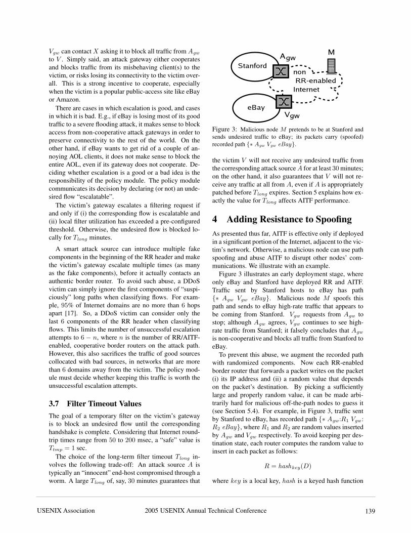
Figure 3: Malicious node M pretends to be at Stanford andsends undesired traffic to eBay; its packets carry (spoofed)recorded path {∗ Agw Vgw eBay}.
the victim V will not receive any undesired traffic fromthe corresponding attack source A for at least 30 minutes;on the other hand, it also guarantees that V will not re-ceive any traffic at all from A, even if A is appropriatelypatched before Tlong expires. Section 5 explains how ex-actly the value for Tlong affects AITF performance.
4 Adding Resistance to SpoofingAs presented thus far, AITF is effective only if deployedin a significant portion of the Internet, adjacent to the vic-tim’s network. Otherwise, a malicious node can use pathspoofing and abuse AITF to disrupt other nodes’ com-munications. We illustrate with an example.
Figure 3 illustrates an early deployment stage, whereonly eBay and Stanford have deployed RR and AITF.Traffic sent by Stanford hosts to eBay has path{∗ Agw Vgw eBay}. Malicious node M spoofs thispath and sends to eBay high-rate traffic that appears tobe coming from Stanford. Vgw requests from Agw tostop; although Agw agrees, Vgw continues to see high-rate traffic from Stanford; it falsely concludes that Agw
is non-cooperative and blocks all traffic from Stanford toeBay.
To prevent this abuse, we augment the recorded pathwith randomized components. Now each RR-enabledborder router that forwards a packet writes on the packet(i) its IP address and (ii) a random value that dependson the packet’s destination. By picking a sufficientlylarge and properly random value, it can be made arbi-trarily hard for malicious off-the-path nodes to guess it(see Section 5.4). For example, in Figure 3, traffic sentby Stanford to eBay, has recorded path {∗ Agw :R1 Vgw :R2 eBay}, where R1 and R2 are random values insertedby Agw and Vgw respectively. To avoid keeping per des-tination state, each router computes the random value toinsert in each packet as follows:
R = hashkey(D)
where key is a local key, hash is a keyed hash function
2005 USENIX Annual Technical Conference USENIX Association140
and D is the packet’s destination.When Agw receives a request to block undesired flow
F{P}, it checks whether it indeed forwarded F , i.e.,whether P includes the correct random value. If yes,Agw commits to filter F by responding to the handshakeas described in Section 3.4. Otherwise, Agw respondswith the “authentic” path P ′, i.e., the path that includesthe correct random value. So, if the victim’s gatewaysends a filtering request with a spoofed path, the hand-shake consists of just two messages, depicted in Figure 4.
Figure 4: Vgw sends a filtering request against spoofed flowF{P} that appears to be coming from Agw ; Agw responds withthe authentic path P ′, which includes the correct random valueinserted by Agw in all packets addressed to V . We added onemore nonce, to enable Vgw to verify that the response with theauthentic path is indeed coming from Agw .
The victim’s gateway uses the authentic path P ′ to rec-ognize spoofed traffic that claims to be coming from Agw
and block it. For example, in Figure 3, Vgw blocks every-thing that appears to be forwarded by Agw but does notinclude Agw ’s correct random value R1, i.e., Vgw blockstraffic with path {∗Agw:!R1 Vgw eBay}. Note that in thespecific example, Vgw can only block this traffic locally— escalation is not an option, since no other domain hasdeployed AITF.
We defer answering the following questions to latersections: (i) Exactly how large must each random com-ponent be? (ii) A router computes its random valuesbased on a local key; how often does this key expire?(iii) When the local key changes, all random values com-municated to victim gateways as part of the handshakebecome invalid; does the router notify the correspondingvictim gateways?
5 EvaluationIn this section, we use back-of-the-envelope calculationsto show that (i) a victim can have an undesired flowblocked within milliseconds; (ii) the victim’s gatewaycan block a certain number of undesired flows with twoorders of magnitude fewer filters than flows and a rea-sonable amount of DRAM; and (iii) the probability ofabusing AITF can be made arbitrarily low.
5.1 Filtering Response TimeWe define filtering response time Tfr as the time thatelapses from the moment the victim sends a filtering re-quest against an undesired flow, until the victim stopsreceiving the flow. With AITF, this is equal to the one-way delay from the victim to the victim’s gateway plusthe negligible overhead of processing the filtering requestand installing the corresponding temporary filter. I.e., fil-tering response time is a few milliseconds.
If there are compromised routers on the flow’s path,they can agree to filter the flow and later break the agree-ment — recall that each attack gateway is given twochances to cooperate. This results in the victim receiv-ing “spikes” of the undesired flow after Tfr . Spikes arespaced out by at least Ttmp seconds; the number of spikesis bounded from above by 2 × n, where n is the numberof compromised routers on the flow’s path. The effect ofthese spikes on the victim is insignificant, as we demon-strate with later simulation results.
5.2 Filtering Rate, Capacity and GainIn this section, we examine three basic AITF properties:how much attack traffic it blocks, how fast it does so, andat what cost. To quantify these properties, we use threesimple metrics: the filtering rate of a router is the num-ber of flows that the router can block every second; thefiltering capacity, is the number of flows that the routercan keep blocked simultaneously; the filtering gain is thenumber of blocked flows divided by the required numberof filters:
G =Nflows
Nfilters
For example, G = 1 flow/filter means that the router uses1 filter to keep 1 flow blocked.
Victim’s gateway — best-case scenario: Assume all at-tack gateways cooperate and all attack sources complywith their gateways to avoid disconnection. In this case,every time Vgw satisfies 1 filtering request, it spends 1filter for Ttmp seconds and causes 1 flow to be blockedfor Tlong minutes. Thus, if Vgw uses Nfilters filters, itachieves filtering rate Nfilters
Ttmpflows/sec, filtering capacity
Nfilters×Tlong
Ttmpflows, and filtering gain
G =Tlong
Ttmp
For example, assume Ttmp = 1 sec and Tlong = 10 min.With 10, 000 filters, Vgw blocks 10, 000 flows/sec andkeeps 6, 000, 000 flows blocked simultaneously.
If certain attack gateways and/or attack sources do notcooperate, undesired flows occur more than once. Sup-pose each undesired flow occurs on average n times. Inthis case, Vgw spends n temporary filters to cause 1 flow
2005 USENIX Annual Technical Conference USENIX Association 141
to be blocked for Tlong minutes. Thus, filtering rate, ca-pacity and gain drop by a factor of n. For example, ifall attack sources lie to their gateways, each undesiredflow occurs twice. Then, with 10, 000 filters, Vgw blocks5, 000 flows/sec and keeps 3, 000, 000 flows blocked si-multaneously.
Victim’s gateway — worst-case scenario: Now assumethat none of the attack gateways cooperates, filter utiliza-tion exceeds its threshold, Vgw escalates all filtering re-quests, and all escalation attempts fail. In this situation,Vgw blocks traffic from all attack gateways to the victimlocally, which means that with 1 filter, Vgw keeps 1 flowblocked. I.e., Vgw achieves filtering gain G = 1.
So, the maximum number of filters ever needed onVgw to protect a single victim equals the total numberof potential attack gateways. Note that this holds even ifall undesired flows are spoofed — Vgw ends up accept-ing one flow from each alleged attack gateway, so it stillneeds as many filters as there can be attack gateways.
Surprisingly, the number of potential attack gatewaysis only a few tens of thousands. According to BGP datafrom Route Views [3] (retrieved in February 2005), thereare currently 19, 230 Autonomous Systems (ASes); ofthese, roughly 90% correspond to edge domains, whilethe rest are Internet Service Providers (ISPs). We pro-cessed the data with Gao’s algorithm for inferring ASrelationships [15] to get the number of providers peredge domain. Assuming a separate border router percustomer-provider pair, there are only tens of thousandsof border routers that could act as attack gateways.
To summarize, there may be millions of attacksources, but there are only tens of thousands of edge do-mains to host them. A router cannot accommodate a mil-lion filters, but it does accommodate tens of thousands.So, if eBay is under attack, eBay’s gateway may be un-able to locally block each attack source individually, butit is able to locally block each edge domain individu-ally — i.e., each edge domain that does not cooperateto block its own misbehaving clients.
Attack gateway: Every time Agw completes a hand-shake, it spends 1 filter for Ttmp seconds and causes 1flow to be blocked. If the attack source complies (toavoid disconnection), the flow remains blocked for Tlong
minutes, as requested. So, with Nfilters filters, Agw
blocks Nfilters×Tlong
Ttmpflows, i.e., Agw achieves filtering gain
G =Tlong
Ttmp. For example, assume Ttmp = 1 sec and
Tlong = 10 min. Suppose Agw provides connectivity to64, 000 hosts (a class B network). With 256, 000 filters,Agw blocks 2, 400 flows from each one of its clients.
If an attack source does not comply, the correspondingflow recurs before Tlong minutes, Agw completes a sec-ond handshake and spends again a temporary filter forTtmp seconds. However, the attack source gets discon-
nected, which means that it does not come back online,unless it has been cleaned and patched. Thus, if attacksources do not comply, the filtering gain of the attackgateway actually increases, because infected hosts getdisconnected, and Agw does not have to filter their trafficagain.
5.3 DRAM RequirementsShadow memory: Both Vgw and Agw keep a shadowfilter for each flow that has been blocked. So, the maxi-mum number of used shadow filters equals the maximumnumber of flows simultaneously blocked (i.e., the filter-ing capacity). Each shadow entry has form {A Agw :R ... Vgw V }. Assuming R is 64 bits long (see Section5.4) and flows are classified/filtered based on the last 6components of their path, each shadow entry is 320 bitswide (2×32 bits for the IP source and destination, 6×32bits for the non-random RR path components, and 64 bitsfor R). So, to keep a million flows blocked, Vgw needsabout 40 MB of DRAM.
Note that DRAM is not the resource bottleneck; if itwere not for the limited number of wire-speed filters, 40GB of shadow memory would be enough to keep 1 bil-lion undesired flows blocked.
Long-term filters on attack source: An attack sourceis not necessarily a malicious or compromised node; it issimply the sender of a traffic flow deemed undesired byits recipient. An “innocent” host classified as an attacksource needs long-term filters to remember which re-ceivers do not want its traffic (and avoid disconnection).Specifically, to satisfy n requests/sec by its provider, thehost needs n×Tlong filters. However, as opposed to wire-speed filters on routers, software filters on end-hosts arenot a scarce resource.
Note that A does not risk disconnection for not satisfy-ing requests beyond the agreed rate — a correctly func-tioning provider does not overload a customer with filter-ing requests and then disconnect the customer for failingto satisfy them.
5.4 Probability of AbuseOne potential attack against AITF is to try to guess therandomized RR header. For example, consider the topol-ogy of Figure 3 and suppose a set of malicious nodes(like M ) spoof Stanford addresses and send high-ratetraffic to eBay. Vgw contacts Agw , gets the random valuerecorded by Agw on all packets to eBay, and blocks allspoofed traffic. However, by sending a sufficiently largenumber of messages to eBay, the malicious nodes cantry to guess the correct random value by brute force. Ifthey succeed, they can successfully pretend to be Stan-ford hosts and potentially cause all traffic from Stanfordto eBay to be classified as undesired and, thus, blocked.
2005 USENIX Annual Technical Conference USENIX Association142
To limit the probability of such abuse, Agw changesthe process by which it computes its random values ev-ery Tchange minutes. If the random value is N bits long,to guess it with probability p, the malicious nodes mustsend p × 2N messages. The amount of time it takes tosend that many messages to eBay is bounded from be-low by eBay’s maximum packet reception rate B. So,if the random value is N bits long, the malicious nodescan guess it during one Tchange interval with probabil-ity p =
Tchange×B
2N . The probability that the maliciousnodes guess one random value in Tguess minutes is theprobability that they guess the random value in any ofthe Tguess
Tchangeintervals:
Pguess = 1 − (1 −Tchange × B
2N)
TguessTchange
For example, if eBay is connected through a 1 Gbpslink, it receives up to 1.95 million packets/sec.1 SupposeTchange = 10 minutes and N = 64 bits. The probabil-ity that the malicious nodes guess one random value in amonth is 2.74 × 10⁻⁷.
Changing the process that computes the random valuecreates the following problem: Suppose Agw has com-municated random values to a number of victim gate-ways; the moment it changes the process, all communi-cated random values become invalid. To avoid this prob-lem, when Agw responds to a handshake, it communi-cates to the victim’s gateway, not only its current randomvalue, but also the next Tlong
Tchangerandom values and when
they will be valid. By choosing Tchange = Tlong , Agw
must pre-compute one random value.
We should note that the size of the random value can-not be chosen solely based on the desired probability ofabuse; it also affects the bandwidth overhead introducedby RR (because each RR-enabled border router adds arandom value to each forwarded packet). We discuss RRbandwidth overhead in the Appendix, Section A.4.
Another potential attack against AITF is to try to com-promise the 3-way handshake. For example, considerthe topology of Figure 1 and suppose a set of maliciousnodes pretend to be V ’s gateway and initiate 3-way hand-shakes with Agw , asking it to block all traffic to V . As-suming the malicious nodes are not on the path from Agw
to V , they do not see Agw ’s responses and the includednonce, necessary to complete the handshake. However,by sending a sufficiently large number of messages, theycan guess the correct nonce by brute force. Followingsimilar rational as above, the probability to guess onenonce in Tguess minutes depends on Agw ’s maximumpacket reception rate. For example, if Agw is connectedthrough a 10 Gbps link, it receives up to 19.5 millionpackets/sec. Suppose Tchange = 10 minutes and the
nonce size is 64 bits. The probability that the maliciousnodes guess one nonce in a month is 2.74 × 10⁻⁶. Fora 128-bit nonce, the probability becomes 1.3 × 10⁻²⁵.Note that, unlike the random value, the nonce is not in-cluded in every packet forwarded by Agw ; hence, the in-centive to keep it small is less relevant.
5.5 Good Traffic Lost to EscalationEscalation blocks all traffic from a non-cooperative at-tack gateway Agw to the victim; clearly, this can lead toloss of good traffic. The decision to escalate or not ismade by the victim, because the victim is the only onewho can quantify the value of Agw ’s good traffic versusthe damage caused by Agw ’s attack traffic. For example,suppose eBay is under attack by a million attack sources,all connected through AOL; at the same time, it is serv-ing 1, 000 legitimate AOL clients. If the AOL gatewaydoes not cooperate, only eBay can decide whether serv-ing the 1, 000 good AOL clients is worth sustaining the1, 000, 000 bad ones.
Whether a flow is “escalatable” or not depends on thepolicy module. Hence, we cannot compute a general es-timate of the percentage of good traffic lost to escala-tion. However, we do implement a simple policy modulein our simulation, and show how its decisions affect thevictim’s good traffic.
6 Simulation ResultsWe use real Internet routing table data to build a realisticsimulation topology. We simulate different attack scenar-ios, where multiple attack sources (up to a million) attacka single victim, connected through a 100 Mbps link; thevictim’s gateway uses up to 10, 000 filters to protect thevictim. For each scenario, we plot the bandwidth of theattack traffic that reaches the victim as well as the vic-tim’s goodput as a function of time, i.e., we show howfast attack traffic is blocked and how much of the vic-tim’s goodput is restored.
6.1 FrameworkWe built our simulator within the Dartmouth ScalableSimulation Framework (DaSSF) [2]. To create our topol-ogy, we downloaded Internet routing table data from theRoute Views project site [3]. We map each AS andeach edge network to a separate AITF domain — we de-rive AS topology and peering relationships by applyingGao’s algorithm for inferring inter-AS relationships [15]to the Route Views data; we derive edge network topol-ogy by roughly creating one edge network per advertisedclass A and class B prefix. Each AITF domain is repre-sented by one AITF router. AITF routers are intercon-nected through OC-192 (9.953 Gbps) and OC-48 (2.488Gbps) full-duplex links. End-hosts are connected to their
2005 USENIX Annual Technical Conference USENIX Association 143
0 20 40 60 80
100 120
0 1 2 3 4 5 6
Vic
tim’s
Ban
dwid
th
(Mbp
s)
Time (sec)
attack traffic
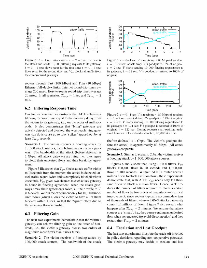
Figure 5: t = 1 sec: attack starts; t = 2 − 3 sec: V detectsthe attack and sends 10, 000 filtering requests to its gateway;t = 3 − 4 sec: flows recur for the first time; t = 4 − 5 sec:flows recur for the second time, and Vgw blocks all traffic fromthe compromised gateways.
routers through Fast (100 Mbps) and Thin (10 Mbps)Ethernet full-duplex links. Internet round-trip times av-erage 200 msec. Host-to-router round-trip times average20 msec. In all scenarios, Ttmp = 1 sec and Tlong = 2min.
6.2 Filtering Response TimeOur first experiment demonstrates that AITF achieves afiltering response time equal to the one-way delay fromthe victim to its gateway, i.e., on the order of millisec-onds. It also demonstrates that “lying” gateways arequickly detected and blocked; the worst each lying gate-way can do is cause up to two “spikes” spaced out by atleast Ttmp seconds.
Scenario 1: The victim receives a flooding attack by10, 000 attack sources, each behind its own attack gate-way. The bandwidth of the attack (before defense) is1 Gbps. All attack gateways are lying, i.e., they agreeto block their undesired flows and then break the agree-ment.
Figure 5 illustrates that Vgw blocks attack traffic withinmilliseconds from the moment the attack is detected; at-tack traffic recurs twice and is completely blocked within2 seconds. Vgw gives two chances to each attack gatewayto honor its filtering agreement; when the attack gate-ways break their agreements twice, all their traffic to V
is blocked. We run the experiment only for 10, 000 unde-sired flows (which allows the victim to have all of themblocked within 1 sec), so that the “spike” effect due tothe recurring flows is visible.
6.3 Filtering GainThe next two experiments demonstrate that the victim’sgateway can achieve filtering gain on the order of hun-dreds, i.e., the victim’s gateway blocks two orders ofmagnitude more flows than it uses filters.
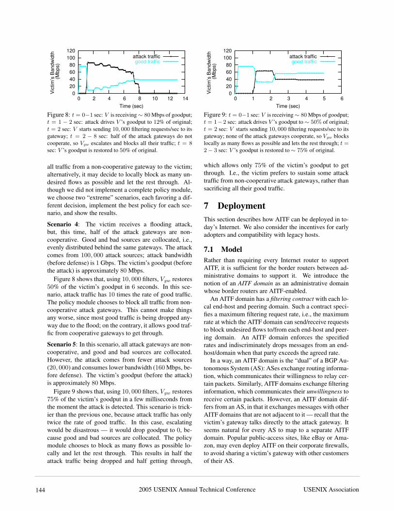
Scenario 2: The victim receives a flooding attack by100, 000 attack sources. The bandwidth of the attack
0 20 40 60 80
100 120
0 2 4 6 8 10 12 14
Vic
tim’s
Ban
dwid
th
(Mbp
s)
Time (sec)
attack trafficgood traffic
Figure 6: t = 0−1 sec: V is receiving ∼ 80 Mbps of goodput;t = 1 − 2 sec: attack drops V ’s goodput to 12% of original;t = 2 sec: V starts sending 10, 000 filtering requests/sec toits gateway; t = 12 sec: V ’s goodput is restored to 100% oforiginal.
0 20 40 60 80
100 120
0 50 100 150 200 250V
ictim
’s B
andw
idth
(M
bps)
Time (sec)
attack trafficgood traffic
Figure 7: t = 0−1 sec: V is receiving ∼ 80 Mbps of goodput;t = 1 − 2 sec: attack drives V ’s goodput to 12% of original;t = 2 sec: V starts sending 10, 000 filtering requests/sec toits gateway; t = 104 sec: V ’s goodput is restored to 100% oforiginal; t = 122 sec: filtering requests start expiring, unde-sired flows are released and re-blocked, 10, 000 at a time.
(before defense) is 1 Gbps. The victim’s goodput (be-fore the attack) is approximately 80 Mbps. All attackgateways cooperate.
Scenario 3: Similar to scenario 2, but the victim receivesa flooding attack by 1, 000, 000 attack sources.
Figures 6 and 7 show that, using 10, 000 filters, Vgw
blocks 100, 000 flows in 10 seconds and 1, 000, 000flows in 100 seconds. Without AITF, a router needs amillion filters to block a million flows; these experimentsdemonstrate that, with AITF, Vgw needs only ten thou-sand filters to block a million flows. Hence, AITF re-duces the number of filters required to block a certainnumber of flows by two orders of magnitude — a criticalimprovement, since routers typically accommodate tensof thousands of filters, whereas DDoS attacks can easilyconsist of millions of flows. Figure 7 also reveals whathappens after Tlong = 2 minutes. We assume that attacksources are “smart”, i.e., they pause sending an undesiredflow when so requested (to avoid disconnection) and theyrestart after Tlong = 2 minutes.
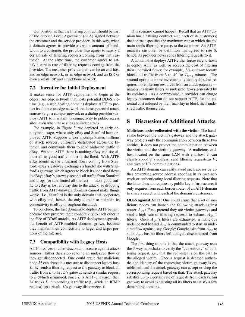
6.4 Escalation and Lost GoodputThe last two experiments illustrate the trade-off involvedin policy decisions regarding non-cooperative gateways.The victim’s gateway may decide to escalate and lose
2005 USENIX Annual Technical Conference USENIX Association144
0 20 40 60 80
100 120
0 2 4 6 8 10 12 14
Vic
tim’s
Ban
dwid
th
(Mbp
s)
Time (sec)
attack trafficgood traffic
Figure 8: t = 0−1 sec: V is receiving ∼ 80 Mbps of goodput;t = 1 − 2 sec: attack drives V ’s goodput to 12% of original;t = 2 sec: V starts sending 10, 000 filtering requests/sec to itsgateway; t = 2 − 8 sec: half of the attack gateways do notcooperate, so Vgw escalates and blocks all their traffic; t = 8
sec: V ’s goodput is restored to 50% of original.
all traffic from a non-cooperative gateway to the victim;alternatively, it may decide to locally block as many un-desired flows as possible and let the rest through. Al-though we did not implement a complete policy module,we choose two “extreme” scenarios, each favoring a dif-ferent decision, implement the best policy for each sce-nario, and show the results.
Scenario 4: The victim receives a flooding attack,but, this time, half of the attack gateways are non-cooperative. Good and bad sources are collocated, i.e.,evenly distributed behind the same gateways. The attackcomes from 100, 000 attack sources; attack bandwidth(before defense) is 1 Gbps. The victim’s goodput (beforethe attack) is approximately 80 Mbps.
Figure 8 shows that, using 10, 000 filters, Vgw restores50% of the victim’s goodput in 6 seconds. In this sce-nario, attack traffic has 10 times the rate of good traffic.The policy module chooses to block all traffic from non-cooperative attack gateways. This cannot make thingsany worse, since most good traffic is being dropped any-way due to the flood; on the contrary, it allows good traf-fic from cooperative gateways to get through.
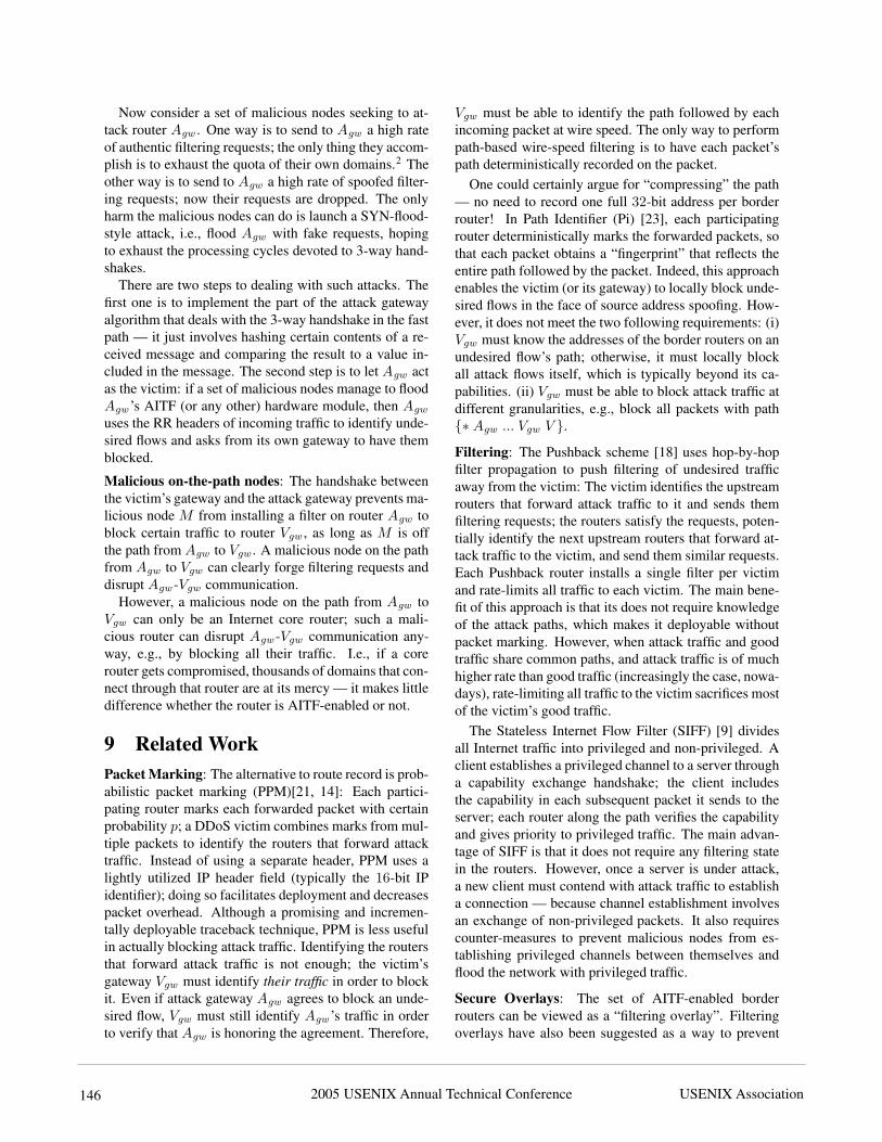
Scenario 5: In this scenario, all attack gateways are non-cooperative, and good and bad sources are collocated.However, the attack comes from fewer attack sources(20, 000) and consumes lower bandwidth (160 Mbps, be-fore defense). The victim’s goodput (before the attack)is approximately 80 Mbps.
Figure 9 shows that, using 10, 000 filters, Vgw restores75% of the victim’s goodput in a few milliseconds fromthe moment the attack is detected. This scenario is trick-ier than the previous one, because attack traffic has onlytwice the rate of good traffic. In this case, escalatingwould be disastrous — it would drop goodput to 0, be-cause good and bad sources are collocated. The policymodule chooses to block as many flows as possible lo-cally and let the rest through. This results in half theattack traffic being dropped and half getting through,
0 20 40 60 80
100 120
0 1 2 3 4 5 6
Vic
tim’s
Ban
dwid
th
(Mbp
s)
Time (sec)
attack trafficgood traffic
Figure 9: t = 0−1 sec: V is receiving ∼ 80 Mbps of goodput;t = 1−2 sec: attack drives V ’s goodput to ∼ 50% of original;t = 2 sec: V starts sending 10, 000 filtering requests/sec to itsgateway; none of the attack gateways cooperate, so Vgw blockslocally as many flows as possible and lets the rest through; t =
2 − 3 sec: V ’s goodput is restored to ∼ 75% of original.
which allows only 75% of the victim’s goodput to getthrough. I.e., the victim prefers to sustain some attacktraffic from non-cooperative attack gateways, rather thansacrificing all their good traffic.
7 DeploymentThis section describes how AITF can be deployed in to-day’s Internet. We also consider the incentives for earlyadopters and compatibility with legacy hosts.
7.1 ModelRather than requiring every Internet router to supportAITF, it is sufficient for the border routers between ad-ministrative domains to support it. We introduce thenotion of an AITF domain as an administrative domainwhose border routers are AITF-enabled.
An AITF domain has a filtering contract with each lo-cal end-host and peering domain. Such a contract speci-fies a maximum filtering request rate, i.e., the maximumrate at which the AITF domain can send/receive requeststo block undesired flows to/from each end-host and peer-ing domain. An AITF domain enforces the specifiedrates and indiscriminately drops messages from an end-host/domain when that party exceeds the agreed rate.
In a way, an AITF domain is the “dual” of a BGP Au-tonomous System (AS): ASes exchange routing informa-tion, which communicates their willingness to relay cer-tain packets. Similarly, AITF domains exchange filteringinformation, which communicates their unwillingness toreceive certain packets. However, an AITF domain dif-fers from an AS, in that it exchanges messages with otherAITF domains that are not adjacent to it — recall that thevictim’s gateway talks directly to the attack gateway. Itseems natural for every AS to map to a separate AITFdomain. Popular public-access sites, like eBay or Ama-zon, may even deploy AITF on their corporate firewalls,to avoid sharing a victim’s gateway with other customersof their AS.
2005 USENIX Annual Technical Conference USENIX Association 145
Our position is that the filtering contract should be partof the Service Level Agreement (SLA) signed betweenthe customer and the service provider. In this way, whena domain agrees to provide a certain amount of band-width to a customer, the provider also agrees to satisfy acertain rate of filtering requests coming from that cus-tomer. At the same time, the customer agrees to sat-isfy a certain rate of filtering requests coming from theprovider. The customer-provider pair can be an end-hostand an edge network, or an edge network and an ISP, oreven a small ISP and a backbone network.
7.2 Incentive for Initial DeploymentIt makes sense for AITF deployment to begin at theedges: An edge network that hosts potential DDoS vic-tims (e.g., a web hosting domain) deploys AITF to pro-tect its clients; an edge network that hosts potential attacksources (e.g., a campus network or a dialup provider) de-ploys AITF to maintain its connectivity to public-accesssites, even when these sites are under attack.
For example, in Figure 3, we depicted an early de-ployment stage, where only eBay and Stanford have de-ployed AITF. Suppose a worm compromises millionsof attack sources, uniformly distributed across the In-ternet, and commands them to send high-rate traffic toeBay. Without AITF, there is nothing eBay can do; al-most all its good traffic is lost in the flood. With AITF,eBay identifies the undesired flows coming from Stan-ford; eBay’s gateway exchanges a handshake with Stan-ford’s gateway, which agrees to block its undesired flowsto eBay; eBay’s gateway accepts all traffic from Stanfordand drops (or rate-limits) all the rest — most good traf-fic to eBay is lost anyway due to the attack, so droppingtraffic from AITF-unaware domains cannot make thingsworse. I.e., Stanford is the only domain that cooperateswith eBay and, hence, the only domain to maintain itsconnectivity to eBay throughout the attack.
To conclude, the first domains to deploy AITF benefit,because they preserve their connectivity to each other inthe face of DDoS attacks. As AITF deployment spreads,the benefit of AITF-enabled domains grows, becausethey maintain their connectivity to larger and larger por-tions of the Internet.
7.3 Compatibility with Legacy HostsAITF involves a rather draconian measure against attacksources: Either they stop sending an undesired flow orthey get disconnected. One could argue that maliciousnode M can abuse this measure to disconnect legacy hostL: M sends a filtering request to L’s gateway to block alltraffic from L to M ; L’s gateway sends a similar requestto L (which is ignored, since L is AITF-unaware); thenM tricks L into sending it traffic (e.g., sends an ICMPrequest); as a result, L’s gateway disconnects L.
This scenario cannot happen. Recall that an AITF do-main has a filtering contract with each of its customers;the contract specifies the maximum rate at which the do-main sends filtering requests to the customer. An AITF-unaware customer by definition has agreed to rate 0;hence, its provider never sends filtering requests to it.
A domain that deploys AITF either forces its end-hoststo deploy AITF as well, or accepts the cost of filteringtheir undesired flows; for example, L’s gateway locallyblocks all traffic from L to M for Tlong minutes. Thesecond option is more incrementally deployable, but re-quires more filtering resources from an attack gateway —namely, as many filters as undesired flows generated byits end-hosts. As a compromise, a provider can chargelegacy customers that do not support AITF, for the po-tential cost induced by their inability to block their unde-sired traffic themselves.
8 Discussion of Additional AttacksMalicious nodes collocated with the victim: The hand-shake between the victim’s gateway and the attack gate-way protects only the communication between these twoentities; it does not protect the communication betweenthe victim and the victim’s gateway. A malicious end-host located on the same LAN with end-host V canclearly spoof V ’s address, send filtering requests as V ,and disrupt V ’s communications.
An AITF domain can easily avoid such abuses by ei-ther preventing source address spoofing in its own net-work or authenticating local filtering requests. Note thatthe latter does not require any public key infrastructure; itonly requires from each border router of an AITF domainto share a secret with each of the domain’s customers.
DDoS against AITF: One could argue that a set of ma-licious nodes can launch the following attack againstrouter Agw : First, pretend they are victim gateways andsend a high rate of filtering requests to exhaust Agw ’sfilters. Once Agw ’s filters are exhausted, a maliciousnode located behind Agw is commanded to start an unde-sired flow against, say, Google; Google asks from Agw tostop, Agw has no filters left and gets disconnected fromGoogle.
The first thing to note is that the attack gateway usesthe 3-way handshake to verify the “authenticity” of a fil-tering request, i.e., that the requester is on the path tothe alleged victim. Once a request is deemed authen-tic, the identity of the requesting victim gateway is es-tablished, and the attack gateway can accept or drop thecorresponding request based on that. The attack gatewaysatisfies up to a certain rate of requests from each victimgateway to avoid exhausting all its filters to satisfy a fewdemanding domains.
2005 USENIX Annual Technical Conference USENIX Association146
Now consider a set of malicious nodes seeking to at-tack router Agw . One way is to send to Agw a high rateof authentic filtering requests; the only thing they accom-plish is to exhaust the quota of their own domains.2 Theother way is to send to Agw a high rate of spoofed filter-ing requests; now their requests are dropped. The onlyharm the malicious nodes can do is launch a SYN-flood-style attack, i.e., flood Agw with fake requests, hopingto exhaust the processing cycles devoted to 3-way hand-shakes.
There are two steps to dealing with such attacks. Thefirst one is to implement the part of the attack gatewayalgorithm that deals with the 3-way handshake in the fastpath — it just involves hashing certain contents of a re-ceived message and comparing the result to a value in-cluded in the message. The second step is to let Agw actas the victim: if a set of malicious nodes manage to floodAgw ’s AITF (or any other) hardware module, then Agw
uses the RR headers of incoming traffic to identify unde-sired flows and asks from its own gateway to have themblocked.
Malicious on-the-path nodes: The handshake betweenthe victim’s gateway and the attack gateway prevents ma-licious node M from installing a filter on router Agw toblock certain traffic to router Vgw , as long as M is offthe path from Agw to Vgw . A malicious node on the pathfrom Agw to Vgw can clearly forge filtering requests anddisrupt Agw -Vgw communication.
However, a malicious node on the path from Agw toVgw can only be an Internet core router; such a mali-cious router can disrupt Agw -Vgw communication any-way, e.g., by blocking all their traffic. I.e., if a corerouter gets compromised, thousands of domains that con-nect through that router are at its mercy — it makes littledifference whether the router is AITF-enabled or not.
9 Related WorkPacket Marking: The alternative to route record is prob-abilistic packet marking (PPM)[21, 14]: Each partici-pating router marks each forwarded packet with certainprobability p; a DDoS victim combines marks from mul-tiple packets to identify the routers that forward attacktraffic. Instead of using a separate header, PPM uses alightly utilized IP header field (typically the 16-bit IPidentifier); doing so facilitates deployment and decreasespacket overhead. Although a promising and incremen-tally deployable traceback technique, PPM is less usefulin actually blocking attack traffic. Identifying the routersthat forward attack traffic is not enough; the victim’sgateway Vgw must identify their traffic in order to blockit. Even if attack gateway Agw agrees to block an unde-sired flow, Vgw must still identify Agw ’s traffic in orderto verify that Agw is honoring the agreement. Therefore,
Vgw must be able to identify the path followed by eachincoming packet at wire speed. The only way to performpath-based wire-speed filtering is to have each packet’spath deterministically recorded on the packet.
One could certainly argue for “compressing” the path— no need to record one full 32-bit address per borderrouter! In Path Identifier (Pi) [23], each participatingrouter deterministically marks the forwarded packets, sothat each packet obtains a “fingerprint” that reflects theentire path followed by the packet. Indeed, this approachenables the victim (or its gateway) to locally block unde-sired flows in the face of source address spoofing. How-ever, it does not meet the two following requirements: (i)Vgw must know the addresses of the border routers on anundesired flow’s path; otherwise, it must locally blockall attack flows itself, which is typically beyond its ca-pabilities. (ii) Vgw must be able to block attack traffic atdifferent granularities, e.g., block all packets with path{∗ Agw ... Vgw V }.
Filtering: The Pushback scheme [18] uses hop-by-hopfilter propagation to push filtering of undesired trafficaway from the victim: The victim identifies the upstreamrouters that forward attack traffic to it and sends themfiltering requests; the routers satisfy the requests, poten-tially identify the next upstream routers that forward at-tack traffic to the victim, and send them similar requests.Each Pushback router installs a single filter per victimand rate-limits all traffic to each victim. The main bene-fit of this approach is that its does not require knowledgeof the attack paths, which makes it deployable withoutpacket marking. However, when attack traffic and goodtraffic share common paths, and attack traffic is of muchhigher rate than good traffic (increasingly the case, nowa-days), rate-limiting all traffic to the victim sacrifices mostof the victim’s good traffic.
The Stateless Internet Flow Filter (SIFF) [9] dividesall Internet traffic into privileged and non-privileged. Aclient establishes a privileged channel to a server througha capability exchange handshake; the client includesthe capability in each subsequent packet it sends to theserver; each router along the path verifies the capabilityand gives priority to privileged traffic. The main advan-tage of SIFF is that it does not require any filtering statein the routers. However, once a server is under attack,a new client must contend with attack traffic to establisha connection — because channel establishment involvesan exchange of non-privileged packets. It also requirescounter-measures to prevent malicious nodes from es-tablishing privileged channels between themselves andflood the network with privileged traffic.
Secure Overlays: The set of AITF-enabled borderrouters can be viewed as a “filtering overlay”. Filteringoverlays have also been suggested as a way to prevent
2005 USENIX Annual Technical Conference USENIX Association 147
DoS against critical applications (like Emergency Ser-vices) that are meant to be accessed only by authorizedusers [16, 12]. In that context, the overlay nodes per-form client authentication and relay traffic to a protectedserver, whose IP address is unknown outside the overlay.
10 Conclusion
We presented Active Internet Traffic Filtering (AITF),a mechanism for filtering highly distributed denial-of-service attacks. We showed that AITF can block a mil-lion undesired flows, while requiring only tens of thou-sands of wire-speed filters from each participating router— an amount easily accommodated by today’s routers.It also prevents abuse by malicious nodes seeking to dis-rupt other nodes’ communications.
More specifically, we showed the following:1. AITF offers filtering response time equal to the one-
way delay from the victim to the victim’s gateway. I.e.,a victim can have an undesired flow blocked within mil-liseconds.
2. AITF offers filtering gain on the order of hundredsof blocked flows per used filter. I.e., a router can blocktwo orders of magnitude more flows than it has wire-speed filters. For example, suppose eBay is receiving amillion undesired flows; with 10, 000 filters, eBay’s gate-way can have all flows blocked within 100 seconds. Inthe worst-case scenario, eBay’s gateway blocks all trafficfrom each domain that hosts attack sources and refusesto filter their traffic, which (in today’s Internet) requiresa few tens of thousands of filters.
3. A set of malicious nodes can practically not abuseAITF to disrupt communication from node A to node B,as long as they are not located on the path from A to B.This holds even during initial deployment, where mostInternet domains are AITF-unaware.
The idea behind AITF is that the Internet does haveenough filtering capacity to block large amounts of un-desired flows — it is just that this capacity is concen-trated close to the attack sources. AITF enables serviceproviders to “gain access” to this filtering capacity andcouple it with a reasonable amount of their own filteringresources, in order to protect their customers in the faceof increasingly distributed denial-of-service attacks.
11 Acknowledgments
We would like to thank Daniel Faria, Evan Greenberg,Dapeng Zhu, George Candea, Nagendra Modadugu,Costa Sapuntzakis, Tassos Argyros and our shepherd,Mema Roussopoulos, for their constructive feedback.
A Appendix: Route RecordA.1 Header UpdateThe RR header consists of three fields: the path is a list of(initially empty) slots; the size is the total number of slotsin the path; the pointer points to the first empty slot in thepath. The first RR-enabled border router on a packet’spath (i) inserts an RR header in the packet; (ii) writes itsown IP address and random value in the first slot; and(iii) sets the pointer to point to the second slot. Eachsubsequent RR-enabled border router that ingresses thepacket into a new AS (i) reads the pointer; (ii) writes itsown IP address and random value in the indicated slot;and (iii) increments the pointer to point to the next slot.If there is no room left in the RR header, the router dropsthe packet.
A.2 Hardware SupportEach RR-enabled border router updates the RR headersof forwarded packets as described in Section A.1. RR-header update requires (i) computing a keyed hash func-tion on the packet’s destination, (ii) reading and modify-ing the RR pointer, and (iii) writing the router’s addressand random value on the indicated slot. So, althoughthe RR header has a variable length, its update requiresreading/modifying a 4-bit pointer and a 96-bit path com-ponent (assuming 64-bit random values). Computing a64-bit hash (like HMAC-SHA1) per forwarded packetcan be easily done today at wire-speed [11].
As mentioned in Section A.1, RR headers are not in-serted by end-hosts; they are inserted by the first bor-der router on each packet’s path — call it the packet’s“gateway”. So, when an edge network deploys RR, it up-grades its border routers to support RR-header insertion.A border router determines the required RR header sizefor each packet, by looking up the AS path length to thepacket’s destination domain as communicated throughBGP. If the real AS path turns out to be longer thanthe communicated AS path, the packet gets dropped; thepacket’s gateway receives an ICMP message, increasesthe RR header size and retransmits the packet — i.e., ASpath length discovery is similar to MTU discovery usingthe “Don’t Fragment” IP-header flag. Once a router dis-covers the real AS path length to a destination domain, itcaches its value to avoid future retransmissions.
RR-header insertion is similar to packet encapsulation,a well-studied operation, for which multiple hardwareimplementations already exist. Note that, as stated inSection 7.2, RR/AITF deployment starts at the edges;i.e., it is edge routers that insert RR headers, not corerouters connected to Internet backbones. Edge routersare connected at best through OC-48 (2.488 Gbps) links;the Cisco 10000 Series OC-48c linecard already supportsencapsulation.
2005 USENIX Annual Technical Conference USENIX Association148
A.3 Compatibility with Legacy HostsBefore inserting an RR header in an outgoing packet, thepacket’s gateway must make sure that the receiving do-main has deployed RR; otherwise, the receiver will notrecognize the RR header and drop the packet. Hence,each packet gateway keeps track of the destination ASesto which it forwards packets, and asks them whether theycare to receive RR headers.
To avoid introducing latency, a packet gateway for-wards packets without inserting RR headers and startsdoing so as soon as it concludes that the destination do-main is RR-enabled. To avoid querying the destinationdomain on each packet, it periodically queries poten-tial destination domains (e.g., once per hour) and cachestheir response. Note that the number of potential des-tination domains can be no bigger than the number ofInternet ASes — 19, 230 for the current Internet.
A.4 Bandwidth OverheadRR bandwidth overhead depends on the average numberof ASes per packet path. Although we do not know thisnumber, we can approximate it with the average numberof AS-level hops between Internet ASes, which is closeto 4 [17, 10]. Assuming an average of 4 ASes per Internetpath and 64-bit random values, route record introduceson average 49 extra bytes per packet. For an averagepacket size of 500 bytes [5], this leads to 10% bandwidthoverhead.
Bandwidth overhead can be reduced to 5% by usingthe following twist: Instead of each router adding a ran-dom value to the recorded path, only one router does so;the first border router that forwards the packet into anRR-unaware domain. For example, consider the topol-ogy in Figure 1; suppose only ANET , AISP and VNET
have deployed AITF. If a packet is sent from A to V ,the only router that adds a random value to the packet’sheader is X . This reduces bandwidth overhead, at thecost of restricting the routing of filtering requests: If V
sends a filtering request against A’s traffic, that requestmust be routed through X , so that X verifies the authen-ticity of the recorded path.
Notes1To make our analysis conservative, we assume that eBay responds
to all the messages sent by the malicious nodes. In reality, if a setof nodes send such high-rate traffic to eBay, eBay will consider theirtraffic undesired and use AITF to have it blocked.
2An AITF-enabled border router can prevent its own clients frompretending to be victim gateways and exhausting its quota, simply bydropping all outgoing filtering requests — recall that no other node butthe border router itself is supposed to send filtering requests outside thelocal domain.
References[1] Access list configuration in Cisco’s Gigabit Ether-
net Interface. http://www.cisco.com/en/US/products/hw/switches/ps5304/prod_configuration_guides_list.html.
[2] Dartmouth scalable simulation framework.http://www.crhc.uiuc.edu/˜jasonliu/projects/ssf/.
[3] Route Views Archive. http://archive.routeviews.org/oix-route-views/.
[4] SiberCore SCT1842 Features. http://www.sibercore.com/products_siberCAM.htm#3.
[5] Sprint backbone data. http://ipmon.sprint.com/packstat/packetoverview.php.
[6] SCO Offline from Denial-of-Service Attack. http://www.caida.org/analysis/security/sco-dos/, December 2003.
[7] Attack downs Yahoo, Google. http://news.zdnet.co.uk/internet/security/0,39020375,39157748,00.htm, June 2004.
[8] DDoS Attack Knocks Out DoubleClick Ads.http://www.eweek.com/article2/0,1759,1628340,00.asp, July 2004.
[9] SIFF: A Stateless Internet Flow Filter to Mitigate DDoSFlooding Attacks. In IEEE Security and Privacy, May2004.
[10] BGP table data. http://bgp.potaroo.net/index-bgp.html, February 2005.
[11] Personal communication with Fusun Ertemalp, Distin-guished Engineer at Cisco Systems, February 2005.
[12] D. G. Andersen. Mayday: Distributed Filtering for Inter-net Services. In USITS, March 2003.
[13] D. J. Bernstein. SYN Cookies. http://cr.yp.to/syncookies.html, 1996.
[14] D. Dean, M. Franklin, and A. Stubblefield. An AlgebraicApproach to IP Traceback. NDSS, February 2001.
[15] L. Gao. On Inferring Autonomous System Relationshipsin the Internet. In Global Internet, November 2000.
[16] A. D. Keromytis, V. Misra, and D. Rubenstein. SecureOverlay Services. In ACM SIGCOMM, August 2002.
[17] D. Magoni and J. J. Pansiot. Analysis of the AutonomousSystem Network Topology. ACM CCR, 31(3):26–37, July2001.
[18] R. Mahajan, S. Bellovin, S. Floyd, J. Ioannidis, V. Paxson,and S. Schenker. Controlling High Bandwidth Aggregatesin the Network. ACM CCR, 32(3):62–73, July 2002.
[19] D. A. Patterson. A simple way to estimate the cost ofdowntime. In USENIX Systems Administration Confer-ence, November 2002.
[20] J. Postel. RFC 791 - Internet Protocol.[21] S. Savage, D. Wetherall, A. Karlin, and T. Anderson.
Practical Network Support for IP Traceback. In ACMSIGCOMM, August 2000.
[22] S. Staniford, V. Paxson, and N. Weaver. How to 0wn theInternet in Your Spare Time. In USENIX Security, August2002.
[23] A. Yaar, A. Perrig, and D. Song. Pi: A Path IdentificationMechanism to Defend against DDoS Attacks. In IEEESecurity and Privacy, May 2003.


![1894 IEEE/ACM TRANSACTIONS ON AUDIO, …azadproject.ir/.../01/High-Precision-Parallel-Graphic-Equalizer.pdfof the equalizer filters, or band filters, ... [31]–[33]. This paper](https://img.pdfslide.us/doc/110x75/5af8066c7f8b9aac248c940e/1894-ieeeacm-transactions-on-audio-the-equalizer-lters-or-band-lters.jpg)