Embed Size (px)
Citation preview
ACTIVE CORE TECHNOLOGY WITHIN THE NEWAC RESEARCH PROGRAM FOR CLEANER AND MORE EFFICIENT AERO ENGINES
S. Bock, W. Horn, G. Wilfert, J. Sieber MTU Aero Engines Dachauer Str. 665 80995 München
Germany
OVERVIEW
The continuous growth of air traffic and the heightened environmental consciousness put increasing pressure on the aero engine manufacturers to reduce fuel burn and emissions. As part of a roadmap to fulfill ambitious emission reduction targets as defined by ACARE, the NEWAC (New Aero Engine Core Concepts) program was established. Under NEWAC, four different core configurations are being investigated:
� Intercooled recuperative aero engine � Intercooled core � Active core � Flow controlled core
These configurations are complemented by the development of innovative combustor technologies.
Within NEWAC, critical components are being designed and manufactured in order to be validated in various rig and core tests
This paper presents the overall structure of NEWAC and focuses on the sub-project Active Core. In this sub-project, the emphasis lies on active systems in the core which will alter and improve current thermodynamic cycles.
Two approaches are presented, one using advanced cooling air cooling in order to save cooling air mass flow, and the other using active controls in the high pressure compressor to improve surge margin and efficiency.
This paper addresses problems associated with active cooling air cooling such as increased weight and HPT life requirements, the proposed solutions to overcome these known issues and the planned activities within NEWAC to verify these solutions.
In a similar manner, this paper discusses various active control technologies under consideration in the HPC such as air injection and active clearance control, and presents a strategy on how to select appropriate combinations of these technologies and compare them to passive alternatives.
In the final chapter, the paper describes the efforts undertaken to foster the close collaboration between industry and academic research and the steps planned within the NEWAC program to lead to more integration within the European research community
ABBREVIATIONS
AEROHEX Advanced Exhaust Gas Recuperator Tech-nology for Aero-Engine Applications
ACAC Active Cooling Air Cooling
ACARE Advisory Council of Aeronautic Research in Europe
ACC Active Clearance Control
ASC Active Surge Control
BPR Bypass Ratio
CFD Computational Fluid Dynamics
CLEAN Component Validator for Environmentally Friendly Aero-Engine
CO2 Carbon Dioxide
EEFAE Efficient and Environmentally Friendly Aero- Engine
EU European Union
HP High Pressure
HPC High Pressure Compressor
LDI Lean Direct Injection
LPP Lean Premixed Prevaporized
NEWAC New Aero Engine Core Concepts
NOx Nitrogen Oxides
OPR Overall Pressure Ratio
PERM Partial Evaporation and Rapid Mixing
SFC Specific Fuel Consumption
SP Sub-Project
SRA Strategic Research Agenda
TERA Technoeconomic and Environmental Risk Analysis
VITAL Environmentally Friendly Engine
1. INTRODUCTION
With the increasing amount of air traffic, the reduction of its negative environmental impacts is becoming ever more important. Over the last 40 years, aero engines have already improved tremendously in fuel consumption, noise and air pollutant emissions as well as reliability, but with increasing evidence for global warming and increasing air traffic density, even more improvement is needed.
Research for cleaner, more efficient aero engines was focused after the Vision 2020 report was published by ACARE Strategic Research Agenda (SRA) which defined ambitious goals in the areas of NOx, noise and CO2 reduction. In order to reach these goals, several research projects have been launched.
One major project, the EU integrated project VITAL [1], is focusing on technologies for low pressure system improvements to reduce CO2 and noise. To further reduce these emissions and also reduce the NOx production, however, complementary research has to be performed on the high pressure components and combustor technology in order to achieve the Vision 2020 objectives. This research is performed in the EU integrated program for NEW Aero engine Core concepts (NEWAC).
2. OVERVIEW OF THE ACTIVITIES WITHIN NEWAC
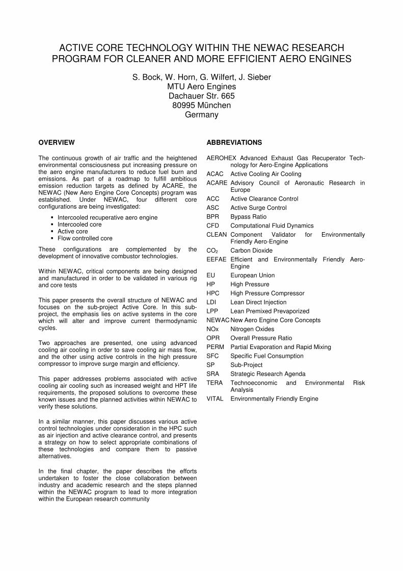
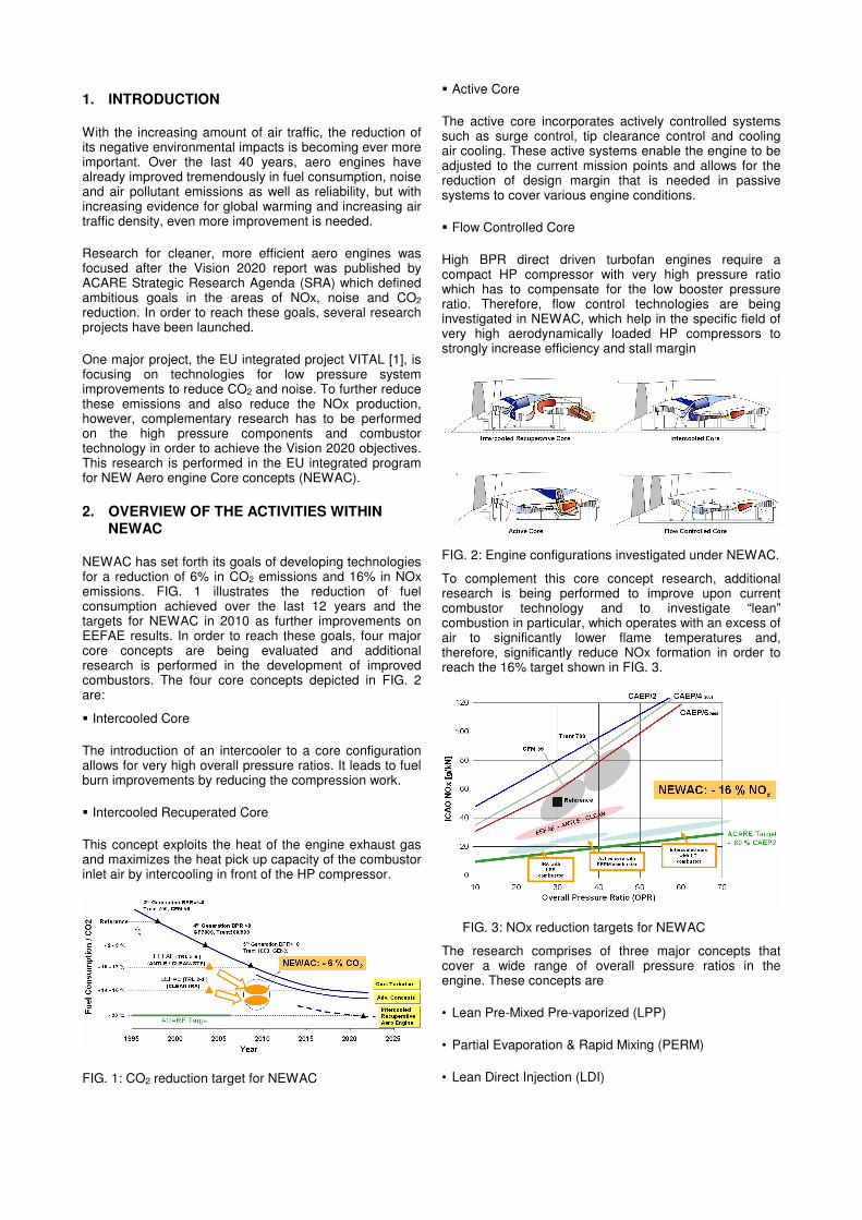
NEWAC has set forth its goals of developing technologies for a reduction of 6% in CO2 emissions and 16% in NOx emissions. FIG. 1 illustrates the reduction of fuel consumption achieved over the last 12 years and the targets for NEWAC in 2010 as further improvements on EEFAE results. In order to reach these goals, four major core concepts are being evaluated and additional research is performed in the development of improved combustors. The four core concepts depicted in FIG. 2 are:
� Intercooled Core
The introduction of an intercooler to a core configuration allows for very high overall pressure ratios. It leads to fuel burn improvements by reducing the compression work.
� Intercooled Recuperated Core
This concept exploits the heat of the engine exhaust gas and maximizes the heat pick up capacity of the combustor inlet air by intercooling in front of the HP compressor.
FIG. 1: CO2 reduction target for NEWAC
� Active Core
The active core incorporates actively controlled systems such as surge control, tip clearance control and cooling air cooling. These active systems enable the engine to be adjusted to the current mission points and allows for the reduction of design margin that is needed in passive systems to cover various engine conditions.
� Flow Controlled Core
High BPR direct driven turbofan engines require a compact HP compressor with very high pressure ratio which has to compensate for the low booster pressure ratio. Therefore, flow control technologies are being investigated in NEWAC, which help in the specific field of very high aerodynamically loaded HP compressors to strongly increase efficiency and stall margin
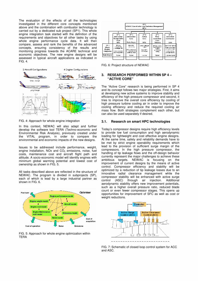
To complement this core concept research, additional research is being performed to improve upon current combustor technology and to investigate “lean” combustion in particular, which operates with an excess of air to significantly lower flame temperatures and, therefore, significantly reduce NOx formation in order to reach the 16% target shown in FIG. 3.
The research comprises of three major concepts that cover a wide range of overall pressure ratios in the engine. These concepts are
• Lean Pre-Mixed Pre-vaporized (LPP)
• Partial Evaporation & Rapid Mixing (PERM)
• Lean Direct Injection (LDI)
FIG. 2: Engine configurations investigated under NEWAC.
FIG. 3: NOx reduction targets for NEWAC
The evaluation of the effects of all the technologies investigated in the different core concepts mentioned above and the combination with combustor technology is carried out by a dedicated sub project (SP1). This whole engine integration task started with the definition of the requirements and objectives for all other tasks by using whole engine performance cycle data. It will then compare, assess and rank the benefits of the advanced concepts, ensuring consistency of the results and monitoring progress towards the ACARE technical and economic objectives. The new engine designs will be assessed in typical aircraft applications as indicated in FIG. 4.
In this context, NEWAC will also adapt and further develop the software tool TERA (Techno-economic and Environmental Risk Analysis), previously created under the VITAL program, in order to compare the environmental and economic impacts of the new designs.
Issues to be addressed include performance, weight, engine installation, NOx and CO2 emissions, noise, fuel costs, maintenance cost and aircraft flight path and altitude. A socio-economic model will identify engines with minimum global warming potential and lowest cost of ownership as shown in FIG. 5.
All tasks described above are reflected in the structure of NEWAC. The program is divided in subprojects (SP), each of which is lead by a large industrial partner as shown in FIG. 6.
3. RESEARCH PERFORMED WITHIN SP 4 – “ACTIVE CORE”
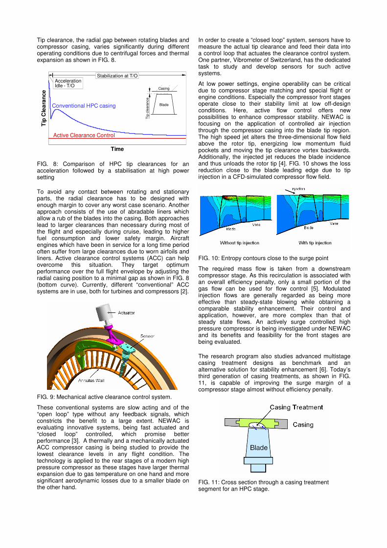
The “Active Core” research is being performed in SP 4 and its concept follows two major strategies. First, it aims at developing new active systems to improve stability and efficiency of the high pressure compressor and second, it tries to improve the overall core efficiency by cooling of high pressure turbine cooling air in order to improve the cooling efficiency and reduce the required cooling air mass flow. Both strategies complement each other, but can also be used separately if desired.
3.1. Research on smart HPC technologies
Today’s compressor designs require high efficiency levels to provide low fuel consumption and high aerodynamic loading for lightweight and cost effective engine designs. At the same time, safety and reliability demands have to be met by strict engine operability requirements which lead to the provision of sufficient surge margin of the compressors. In the high pressure compressor, the handling of tip leakage flows and the off-design behavior currently represent the major challenges to achieve these ambitious targets. NEWAC is focusing on the improvement of current designs by the means of active control. Compressor efficiency and stability will be optimized by a reduction of tip leakage losses due to an innovative radial clearance management while the compressor stability will be enhanced with active surge control (ASC) through air injection. Additional aerodynamic stability offers new improvement potentials, such as a higher overall pressure ratio, reduced blade count or even fewer compressor stages. This opens up opportunities for improvement of SFC as well as cost or weight reductions.
FIG. 4: Approach for whole engine integration
FIG. 5: Approach for whole engine optimization within TERA
FIG. 6: Project structure of NEWAC
FIG. 7: Schematic of closed loop control system for ACC and ASC.
Tip clearance, the radial gap between rotating blades and compressor casing, varies significantly during different operating conditions due to centrifugal forces and thermal expansion as shown in FIG. 8.
Time
Tip
Cle
ara
nce
Conventional HPC casing
Active Clearance Control
Stabilization at T/OAccelerationIdle - T/O
Tip
cle
ara
nce
Blade
Casing
FIG. 8: Comparison of HPC tip clearances for an acceleration followed by a stabilisation at high power setting
To avoid any contact between rotating and stationary parts, the radial clearance has to be designed with enough margin to cover any worst case scenario. Another approach consists of the use of abradable liners which allow a rub of the blades into the casing. Both approaches lead to larger clearances than necessary during most of the flight and especially during cruise, leading to higher fuel consumption and lower safety margin. Aircraft engines which have been in service for a long time period often suffer from large clearances due to worn airfoils and liners. Active clearance control systems (ACC) can help overcome this situation. They target optimum performance over the full flight envelope by adjusting the radial casing position to a minimal gap as shown in FIG. 8 (bottom curve). Currently, different “conventional” ACC systems are in use, both for turbines and compressors [2].
These conventional systems are slow acting and of the “open loop” type without any feedback signals, which constricts the benefit to a large extent. NEWAC is evaluating innovative systems, being fast actuated and “closed loop” controlled, which promise better performance [3]. A thermally and a mechanically actuated ACC compressor casing is being studied to provide the lowest clearance levels in any flight condition. The technology is applied to the rear stages of a modern high pressure compressor as these stages have larger thermal expansion due to gas temperature on one hand and more significant aerodynamic losses due to a smaller blade on the other hand.
In order to create a “closed loop” system, sensors have to measure the actual tip clearance and feed their data into a control loop that actuates the clearance control system. One partner, Vibrometer of Switzerland, has the dedicated task to study and develop sensors for such active systems.
At low power settings, engine operability can be critical due to compressor stage matching and special flight or engine conditions. Especially the compressor front stages operate close to their stability limit at low off-design conditions. Here, active flow control offers new possibilities to enhance compressor stability. NEWAC is focusing on the application of controlled air injection through the compressor casing into the blade tip region. The high speed jet alters the three-dimensional flow field above the rotor tip, energizing low momentum fluid pockets and moving the tip clearance vortex backwards. Additionally, the injected jet reduces the blade incidence and thus unloads the rotor tip [4]. FIG. 10 shows the loss reduction close to the blade leading edge due to tip injection in a CFD-simulated compressor flow field.
The required mass flow is taken from a downstream compressor stage. As this recirculation is associated with an overall efficiency penalty, only a small portion of the gas flow can be used for flow control [5]. Modulated injection flows are generally regarded as being more effective than steady-state blowing while obtaining a comparable stability enhancement. Their control and application, however, are more complex than that of steady state flows. An actively surge controlled high pressure compressor is being investigated under NEWAC and its benefits and feasibility for the front stages are being evaluated.
The research program also studies advanced multistage casing treatment designs as benchmark and an alternative solution for stability enhancement [6]. Today’s third generation of casing treatments, as shown in FIG. 11, is capable of improving the surge margin of a compressor stage almost without efficiency penalty.
FIG. 9: Mechanical active clearance control system.
FIG. 10: Entropy contours close to the surge point
FIG. 11: Cross section through a casing treatment segment for an HPC stage.
The aerodynamic design and prediction is a challenging task, however, as the related flow mechanisms are highly complex and the calculation of aerodynamic stability requires the use of unsteady CFD codes over several stages. In addition to the goal of significant stability enhancement, the design point efficiency will be improved as well by lowering the tip clearance sensitivity of the rear stages. Besides the impact on aerodynamics, design issues like producibility, weight and cost will be addressed.
The smart compressor technology eliminates the need to design for worst case requirements and enables an engine optimization to standard flight missions. Active control offers the possibility of adapting the core engine to each operating condition and, therefore, allows an optimization of component and cycle behavior. The compressor can be designed for better efficiency, higher power density, lower size and weight. Finally, efficiency and safety penalties due to deterioration can be compensated, to a certain degree, by adjusting the core to actual conditions.
All these benefits will be assessed and quantified under NEWAC and weighed against the drawbacks of each individual technology, including weight, cost or complexity. This overall evaluation will be performed in various models on component, module and whole engine level. This task will be closely related to the work performed in SP 1.
3.2. Research on active cooling air cooling
Modern jet engines with their high turbine entry temperatures require effective cooling in order not to exceed the limits of the used materials. In today’s engines, the total cooling air consumption is in the order of 25% which represents a significant portion of the total air flow. While some of this air still participates in the thermodynamic cycle, it still causes a deterioration of the overall engine performance.
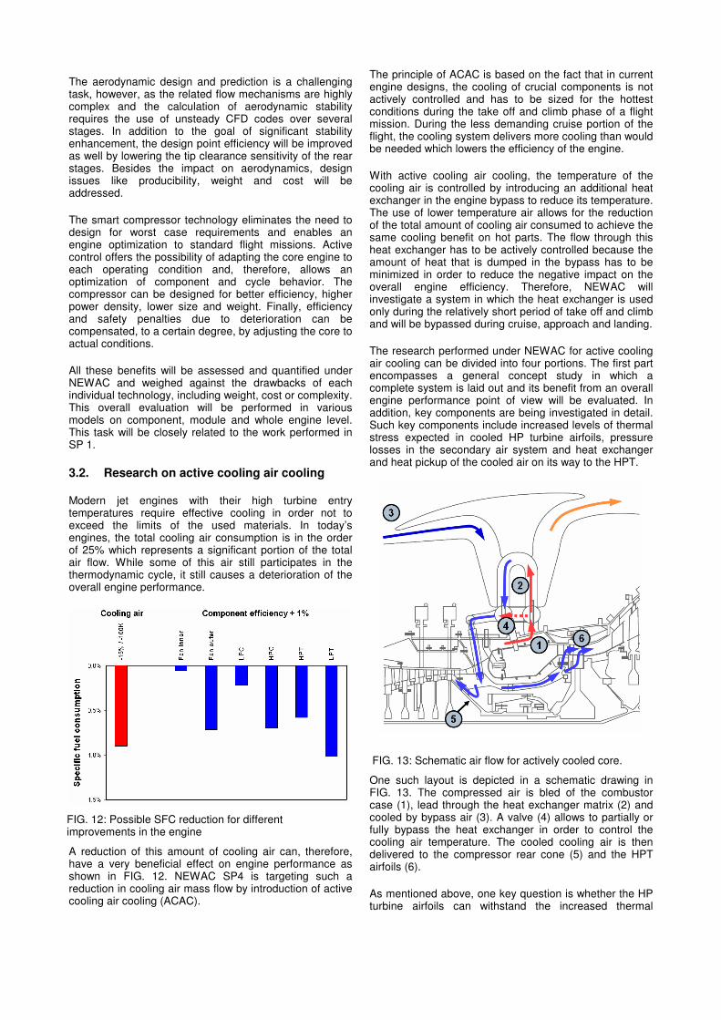
A reduction of this amount of cooling air can, therefore, have a very beneficial effect on engine performance as shown in FIG. 12. NEWAC SP4 is targeting such a reduction in cooling air mass flow by introduction of active cooling air cooling (ACAC).
The principle of ACAC is based on the fact that in current engine designs, the cooling of crucial components is not actively controlled and has to be sized for the hottest conditions during the take off and climb phase of a flight mission. During the less demanding cruise portion of the flight, the cooling system delivers more cooling than would be needed which lowers the efficiency of the engine.
With active cooling air cooling, the temperature of the cooling air is controlled by introducing an additional heat exchanger in the engine bypass to reduce its temperature. The use of lower temperature air allows for the reduction of the total amount of cooling air consumed to achieve the same cooling benefit on hot parts. The flow through this heat exchanger has to be actively controlled because the amount of heat that is dumped in the bypass has to be minimized in order to reduce the negative impact on the overall engine efficiency. Therefore, NEWAC will investigate a system in which the heat exchanger is used only during the relatively short period of take off and climb and will be bypassed during cruise, approach and landing.
The research performed under NEWAC for active cooling air cooling can be divided into four portions. The first part encompasses a general concept study in which a complete system is laid out and its benefit from an overall engine performance point of view will be evaluated. In addition, key components are being investigated in detail. Such key components include increased levels of thermal stress expected in cooled HP turbine airfoils, pressure losses in the secondary air system and heat exchanger and heat pickup of the cooled air on its way to the HPT.
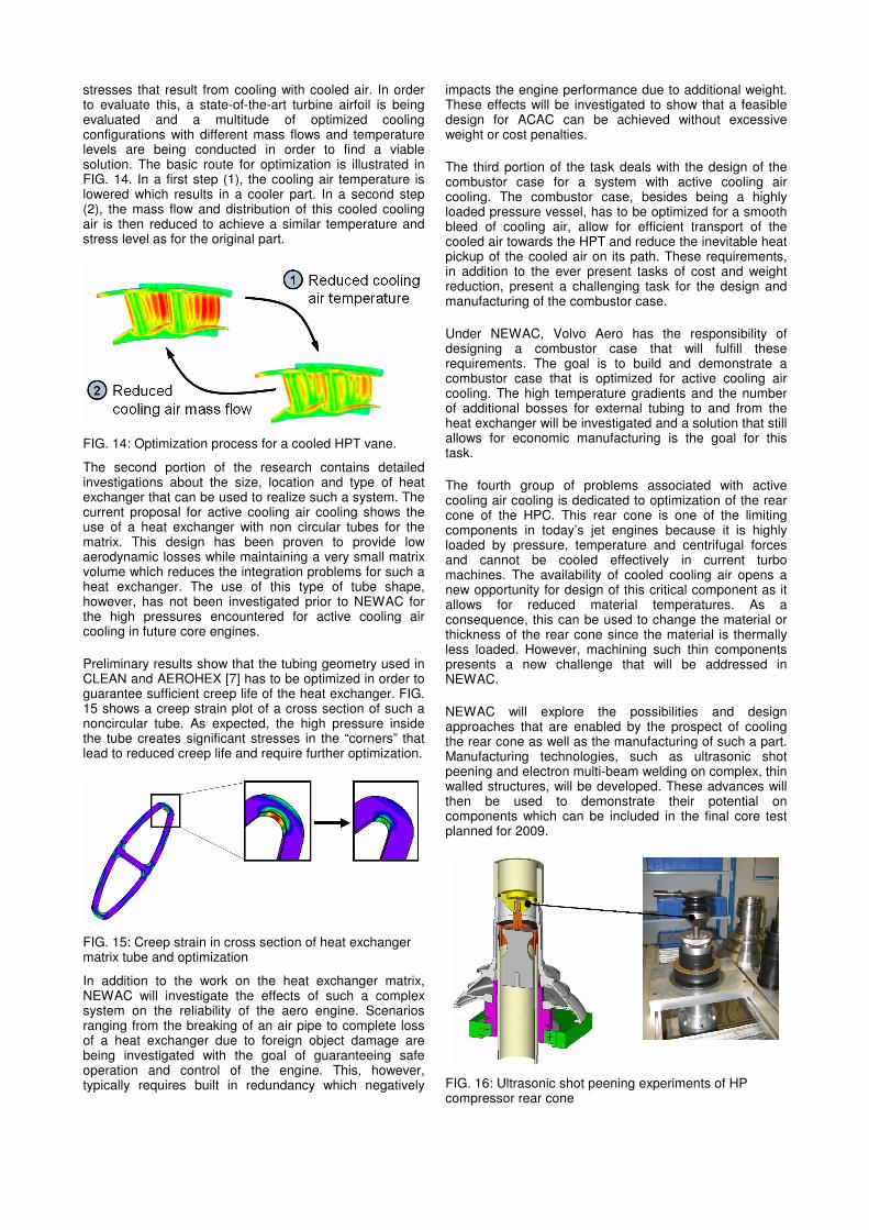
One such layout is depicted in a schematic drawing in FIG. 13. The compressed air is bled of the combustor case (1), lead through the heat exchanger matrix (2) and cooled by bypass air (3). A valve (4) allows to partially or fully bypass the heat exchanger in order to control the cooling air temperature. The cooled cooling air is then delivered to the compressor rear cone (5) and the HPT airfoils (6).
As mentioned above, one key question is whether the HP turbine airfoils can withstand the increased thermal
FIG. 12: Possible SFC reduction for different improvements in the engine
FIG. 13: Schematic air flow for actively cooled core.
stresses that result from cooling with cooled air. In order to evaluate this, a state-of-the-art turbine airfoil is being evaluated and a multitude of optimized cooling configurations with different mass flows and temperature levels are being conducted in order to find a viable solution. The basic route for optimization is illustrated in FIG. 14. In a first step (1), the cooling air temperature is lowered which results in a cooler part. In a second step (2), the mass flow and distribution of this cooled cooling air is then reduced to achieve a similar temperature and stress level as for the original part.
The second portion of the research contains detailed investigations about the size, location and type of heat exchanger that can be used to realize such a system. The current proposal for active cooling air cooling shows the use of a heat exchanger with non circular tubes for the matrix. This design has been proven to provide low aerodynamic losses while maintaining a very small matrix volume which reduces the integration problems for such a heat exchanger. The use of this type of tube shape, however, has not been investigated prior to NEWAC for the high pressures encountered for active cooling air cooling in future core engines.
Preliminary results show that the tubing geometry used in CLEAN and AEROHEX [7] has to be optimized in order to guarantee sufficient creep life of the heat exchanger. FIG. 15 shows a creep strain plot of a cross section of such a noncircular tube. As expected, the high pressure inside the tube creates significant stresses in the “corners” that lead to reduced creep life and require further optimization.
In addition to the work on the heat exchanger matrix, NEWAC will investigate the effects of such a complex system on the reliability of the aero engine. Scenarios ranging from the breaking of an air pipe to complete loss of a heat exchanger due to foreign object damage are being investigated with the goal of guaranteeing safe operation and control of the engine. This, however, typically requires built in redundancy which negatively
impacts the engine performance due to additional weight. These effects will be investigated to show that a feasible design for ACAC can be achieved without excessive weight or cost penalties.
The third portion of the task deals with the design of the combustor case for a system with active cooling air cooling. The combustor case, besides being a highly loaded pressure vessel, has to be optimized for a smooth bleed of cooling air, allow for efficient transport of the cooled air towards the HPT and reduce the inevitable heat pickup of the cooled air on its path. These requirements, in addition to the ever present tasks of cost and weight reduction, present a challenging task for the design and manufacturing of the combustor case.
Under NEWAC, Volvo Aero has the responsibility of designing a combustor case that will fulfill these requirements. The goal is to build and demonstrate a combustor case that is optimized for active cooling air cooling. The high temperature gradients and the number of additional bosses for external tubing to and from the heat exchanger will be investigated and a solution that still allows for economic manufacturing is the goal for this task.
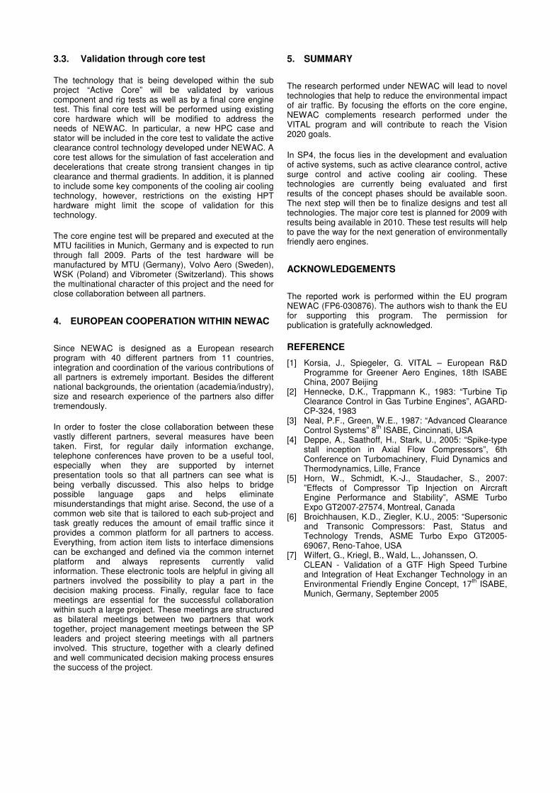
The fourth group of problems associated with active cooling air cooling is dedicated to optimization of the rear cone of the HPC. This rear cone is one of the limiting components in today’s jet engines because it is highly loaded by pressure, temperature and centrifugal forces and cannot be cooled effectively in current turbo machines. The availability of cooled cooling air opens a new opportunity for design of this critical component as it allows for reduced material temperatures. As a consequence, this can be used to change the material or thickness of the rear cone since the material is thermally less loaded. However, machining such thin components presents a new challenge that will be addressed in NEWAC.
NEWAC will explore the possibilities and design approaches that are enabled by the prospect of cooling the rear cone as well as the manufacturing of such a part. Manufacturing technologies, such as ultrasonic shot peening and electron multi-beam welding on complex, thin walled structures, will be developed. These advances will then be used to demonstrate their potential on components which can be included in the final core test planned for 2009.
FIG. 14: Optimization process for a cooled HPT vane.
FIG. 15: Creep strain in cross section of heat exchanger matrix tube and optimization
FIG. 16: Ultrasonic shot peening experiments of HP compressor rear cone
3.3. Validation through core test
The technology that is being developed within the sub project “Active Core” will be validated by various component and rig tests as well as by a final core engine test. This final core test will be performed using existing core hardware which will be modified to address the needs of NEWAC. In particular, a new HPC case and stator will be included in the core test to validate the active clearance control technology developed under NEWAC. A core test allows for the simulation of fast acceleration and decelerations that create strong transient changes in tip clearance and thermal gradients. In addition, it is planned to include some key components of the cooling air cooling technology, however, restrictions on the existing HPT hardware might limit the scope of validation for this technology.
The core engine test will be prepared and executed at the MTU facilities in Munich, Germany and is expected to run through fall 2009. Parts of the test hardware will be manufactured by MTU (Germany), Volvo Aero (Sweden), WSK (Poland) and Vibrometer (Switzerland). This shows the multinational character of this project and the need for close collaboration between all partners.
4. EUROPEAN COOPERATION WITHIN NEWAC
Since NEWAC is designed as a European research program with 40 different partners from 11 countries, integration and coordination of the various contributions of all partners is extremely important. Besides the different national backgrounds, the orientation (academia/industry), size and research experience of the partners also differ tremendously.
In order to foster the close collaboration between these vastly different partners, several measures have been taken. First, for regular daily information exchange, telephone conferences have proven to be a useful tool, especially when they are supported by internet presentation tools so that all partners can see what is being verbally discussed. This also helps to bridge possible language gaps and helps eliminate misunderstandings that might arise. Second, the use of a common web site that is tailored to each sub-project and task greatly reduces the amount of email traffic since it provides a common platform for all partners to access. Everything, from action item lists to interface dimensions can be exchanged and defined via the common internet platform and always represents currently valid information. These electronic tools are helpful in giving all partners involved the possibility to play a part in the decision making process. Finally, regular face to face meetings are essential for the successful collaboration within such a large project. These meetings are structured as bilateral meetings between two partners that work together, project management meetings between the SP leaders and project steering meetings with all partners involved. This structure, together with a clearly defined and well communicated decision making process ensures the success of the project.
5. SUMMARY
The research performed under NEWAC will lead to novel technologies that help to reduce the environmental impact of air traffic. By focusing the efforts on the core engine, NEWAC complements research performed under the VITAL program and will contribute to reach the Vision 2020 goals.
In SP4, the focus lies in the development and evaluation of active systems, such as active clearance control, active surge control and active cooling air cooling. These technologies are currently being evaluated and first results of the concept phases should be available soon. The next step will then be to finalize designs and test all technologies. The major core test is planned for 2009 with results being available in 2010. These test results will help to pave the way for the next generation of environmentally friendly aero engines.
ACKNOWLEDGEMENTS
The reported work is performed within the EU program NEWAC (FP6-030876). The authors wish to thank the EU for supporting this program. The permission for publication is gratefully acknowledged.
REFERENCE
[1] Korsia, J., Spiegeler, G. VITAL – European R&D Programme for Greener Aero Engines, 18th ISABE China, 2007 Beijing
[2] Hennecke, D.K., Trappmann K., 1983: “Turbine Tip Clearance Control in Gas Turbine Engines”, AGARD-CP-324, 1983
[3] Neal, P.F., Green, W.E., 1987: “Advanced Clearance Control Systems” 8
th ISABE, Cincinnati, USA
[4] Deppe, A., Saathoff, H., Stark, U., 2005: “Spike-type stall inception in Axial Flow Compressors”, 6th Conference on Turbomachinery, Fluid Dynamics and Thermodynamics, Lille, France
[5] Horn, W., Schmidt, K.-J., Staudacher, S., 2007: ”Effects of Compressor Tip Injection on Aircraft Engine Performance and Stability”, ASME Turbo Expo GT2007-27574, Montreal, Canada
[6] Broichhausen, K.D., Ziegler, K.U., 2005: “Supersonic and Transonic Compressors: Past, Status and Technology Trends, ASME Turbo Expo GT2005-69067, Reno-Tahoe, USA
[7] Wilfert, G., Kriegl, B., Wald, L., Johanssen, O. CLEAN - Validation of a GTF High Speed Turbine and Integration of Heat Exchanger Technology in an Environmental Friendly Engine Concept, 17
th ISABE,
Munich, Germany, September 2005