Embed Size (px)
Citation preview
Activation of a Mobile Robot through a Brain Computer Interface
Alexandre O. G. Barbosa, David R. Achanccaray, and Marco A. Meggiolaro
Abstract - This work presents the development of a brain
computer interface as an alternative communication channel to be used in Robotics. It encompasses the implementation of an electroencephalograph (EEG), as well as the development of all computational methods and necessary techniques to identify mental activities. The developed brain computer interface (BCI) is applied to activate the movements of a 120lb mobile robot, associating four different mental activities to robot commands. The interface is based on EEG signal analyses, which extract features that can be classified as specific mental activities. First, a signal preprocessing is performed from the EEG data, filtering noise, using a spatial filter to increase the scalp signal resolution, and extracting relevant features. Then, different classifier models are proposed, evaluated and compared. At last, two implementations of the developed classifiers are proposed to improve the rate of successful commands to the mobile robot. In one of the implementations, a 91% average hit rate is obtained, with only 1.25% wrong commands after 400 attempts to control the mobile robot.
I. INTRODUCTION he development of interfaces between humans and machines has been an expanding field in the last decades. It includes several interfaces using voice,
vision, haptics, electromyography, electroencephalography (EEG), and combinations among them as a communication support [1]. A system that analyzes brainwaves to derive information about the subjects’ mental state is called a Brain Computer Interface (BCI) [2].
People who are partially or totally paralyzed (e.g., by amyotrophic lateral sclerosis (ALS) or brainstem stroke) or have other severe motor disabilities can find a BCI as an alternative communication channel [3]. BCI systems are used to operate a number of brain-actuated applications that augment people’s communication capabilities, provide new forms of education and entertainment, and also enable the operation of physical devices [2].
There are two types of BCI’s: invasive, which are based on signals recorded from electrodes implanted over the brain cortex (requiring surgery), and non-invasive, based on the analysis of EEG phenomena associated with various aspects of brain function [1].
Manuscript received September 15, 2009. This work was supported in
part by the Fundação de Amparo à Pesquisa do Estado do Rio de Janeiro (FAPERJ) and Coordenação de Aperfeiçoamento de Pessoal de Nível Superior (CAPES).
A. O. G. Barbosa is an M.Sc. Student from the Pontifical Catholic University of Rio de Janeiro, Brazil ([email protected]).
D. R. Achanccaray is a Ph.D. Student from the Pontifical Catholic University of Rio de Janeiro, Brazil ([email protected]).
M. A. Meggiolaro is a Professor from the Pontifical Catholic University of Rio de Janeiro, Brazil ([email protected]).
Birbaumer [4] measured slow cortical potentials (SCP) over the vertex (top of the scalp). SCP are shifts in the depolarization level of the upper cortical dendrites, which indicate the overall preparatory excitation level of a cortical network. Other groups looked at local variations of the EEG rhythms. The most used of such rhythms are related to the imagination of movements, recorded from the central region of the scalp overlying the sensorimotor and pre-sensorimotor cortex. In this respect, there are two main paradigms. Pfurtscheller’s team [5-6] worked with event-related desynchronization (ERD) computed at fixed time intervals after the subject is commanded to imagine specific movements of the limbs. Alternatively, Wolpaw [7] and coworkers analyzed continuous changes in the amplitudes of the mu (8-12 Hz) or beta (13-28 Hz) rhythms.
Finally, in addition to motor-related rhythms, Anderson [8] and Millán [9] analyzed continuous variations of EEG rhythms, but not only over the sensorimotor cortex and in specific frequency bands. The reason is that a number of neurocognitive studies have found that different mental activities (such as imagination of movements, arithmetic operations, or language) activate local cortical areas at different extents. The insights gathered from these studies guide the placement of electrodes to get more relevant signals for the different tasks to be recognized.
BCI applications include control of the elements in a computer-rendered environment such as cursor positioning [1,3] or visiting of a virtual apartment [10], spelling software [11], and command of an external device such as a robot [12] or prosthesis [13]. Recent applications in Robotics are the control of a wheelchair [14-16] and the control of the Khepera mobile robot [17].
In this work, a non-invasive BCI based on EEG analysis is proposed to control a mobile robot. Control is provided through four specific mental activities: imaginary movements of feet, tongue, left arm, and right arm. These activities are correlated with 4 robot movements, respectively: stop, move forward, turn left and turn right. The interface classifies the user’s mental activity, sending the corresponding command to activate the mobile robot. Note that the user does not need to be able to perform such feet, tongue or arm movements, just imagining them is enough to activate the robot.
This paper is organized in seven sections. Section 2 describes the implementation of the electroencephalograph used in this work. Section 3 presents how signals have been preprocessed, followed by Section 4, where classifier models are proposed. Section 5 shows experiments to evaluate the classifiers, while Section 6 shows the application to the mobile robot. Finally, Section 7 discusses the conclusions of this work.
T
2010 IEEE International Conference on Robotics and AutomationAnchorage Convention DistrictMay 3-8, 2010, Anchorage, Alaska, USA
978-1-4244-5040-4/10/$26.00 ©2010 IEEE 4815
II. IMPLEMENTATION OF AN ELECTROENCEPHALOGRAPH An electroencephalograph is a device that records the
brain activity through electrodes placed on the scalp. EEG has an invaluable support to the diagnostic of diseases of the central nervous system (CNS) that compromise the structure of the neurons; i.e., the study of epilepsy, featuring unusual excitability of the neurons [18].
An 8-channel electroencephalograph has been especially developed for this work, consisting of a protection circuit, an instrumental amplifier, a right-leg driver, an amplification circuit, and an analog-digital converter, described next.
A. Protection Circuit The protection circuit is connected to the electrodes. It is
the first stop for the EEG signal entering the system. This initial stage suppresses any RF signals captured by the electrode cables, while limiting the input voltage [19].
B. Instrumental Amplification An instrumental amplifier controls the differential input,
determining the common-mode rejection ratio (CMRR). It is also intended to remove noise from the input signals [19].
C. Right-Leg Driver The Right Leg Driver is used to raise the common-mode
rejection ratio of the instrumentation amplifier [19].
D. Amplification Circuit The amplification circuit is achieved in two stages: first,
two high-pass first order filters are included between the amplifications, with a cutoff frequency of 0.16Hz to remove DC-voltage offsets. Then, a second amplification stage is applied, using a low-pass third order Bessel filter, with a cutoff frequency of 59Hz. This second stage helps to filter power line noises, while keeping the frequencies of interest, which are between 4 and 30Hz. The total gain of the amplifier is about 8000.
E. Analog-Digital Converter The analog-digital (A/D) converter is needed to digitalize
the signals for the subsequent processing in a computer.
Two versions of the EEG have been developed. In the first EEG, shown in Fig. 1, the digitalization is carried out through the data acquisition system CompactDAQ from National Instruments [20], while the other circuits were implemented in especially designed electronic boards.
Fig. 1. First version of the developed electroencephalograph.
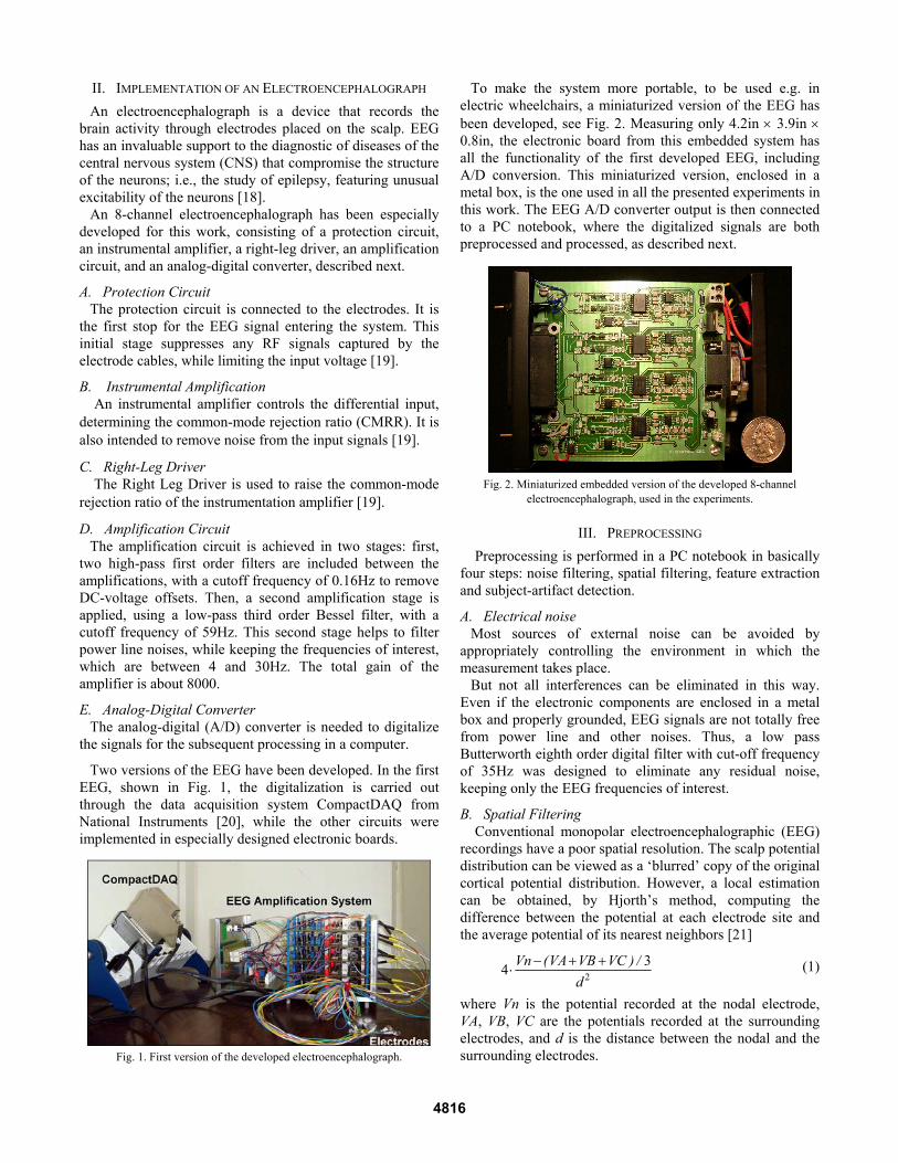
To make the system more portable, to be used e.g. in electric wheelchairs, a miniaturized version of the EEG has been developed, see Fig. 2. Measuring only 4.2in × 3.9in × 0.8in, the electronic board from this embedded system has all the functionality of the first developed EEG, including A/D conversion. This miniaturized version, enclosed in a metal box, is the one used in all the presented experiments in this work. The EEG A/D converter output is then connected to a PC notebook, where the digitalized signals are both preprocessed and processed, as described next.
Fig. 2. Miniaturized embedded version of the developed 8-channel
electroencephalograph, used in the experiments.
III. PREPROCESSING Preprocessing is performed in a PC notebook in basically
four steps: noise filtering, spatial filtering, feature extraction and subject-artifact detection.
A. Electrical noise Most sources of external noise can be avoided by
appropriately controlling the environment in which the measurement takes place.
But not all interferences can be eliminated in this way. Even if the electronic components are enclosed in a metal box and properly grounded, EEG signals are not totally free from power line and other noises. Thus, a low pass Butterworth eighth order digital filter with cut-off frequency of 35Hz was designed to eliminate any residual noise, keeping only the EEG frequencies of interest.
B. Spatial Filtering Conventional monopolar electroencephalographic (EEG) recordings have a poor spatial resolution. The scalp potential distribution can be viewed as a ‘blurred’ copy of the original cortical potential distribution. However, a local estimation can be obtained, by Hjorth’s method, computing the difference between the potential at each electrode site and the average potential of its nearest neighbors [21]
234 Vn (VA VB VC ) /
d− + +
⋅ (1)
where Vn is the potential recorded at the nodal electrode, VA, VB, VC are the potentials recorded at the surrounding electrodes, and d is the distance between the nodal and the surrounding electrodes.
4816

C. Feature extraction Due to brain specialization, electrodes placed on the
frontal (located near the pre-motor cortex area), center (at the motor cortex area) and parietal locations are chosen to acquire EEG signals. They correspond to F3, Fz, F4, C3, Cz, C4, P3 and P4 locations, according to the International System 10-20 of Electrode Placement, shown in Fig. 3.
Fig. 3. Electrode positions from the International System 10-20.
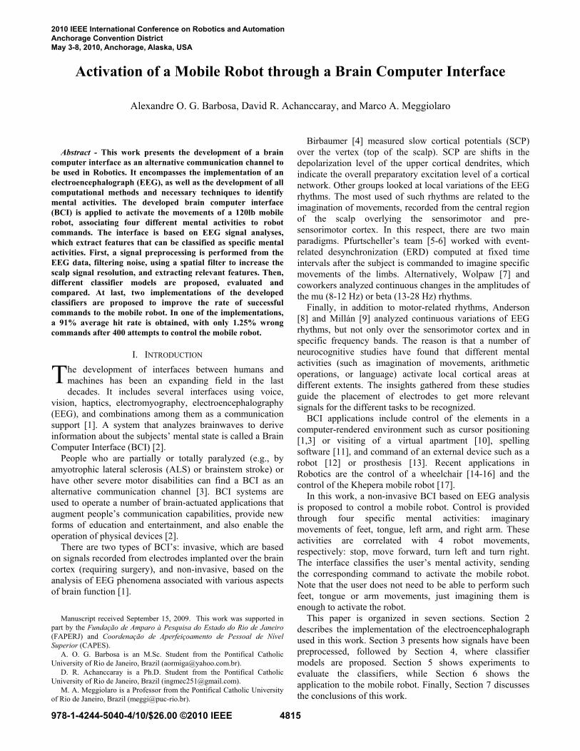
EEG signals from each one of the 8 channels are decomposed through a Discrete Wavelet Transform (DWT) until achieving the frequency range of the brainwaves. The DWT is applied in seven levels, shown in Fig. 4, to approximately represent the four principal frequency ranges of the brainwaves [22]:
• Delta Band [0 – 4 Hz]: (n). • Theta Band [4 – 8 Hz]: (o). • Alpha Band [8 – 13 Hz]: (m). • Beta Band [13 – 30 Hz]: (k).
Fig. 4. DWT decomposition of the frequency range.
The chosen sample rate is 1 kHz, so the decomposition of frequency ranges begins in the range between 0 and 500 Hz.
Most mental tasks related to imagery movements show higher activity in the alpha and beta bands [3], therefore these frequencies are chosen to be processed.
A Multi Layer Perceptron Neural Network is designed to evaluate the relevance of some extracted features from the selected levels from the DWT decomposition. In this work, a series of 10 datasets composed each by 700 EEG samples from the same subject is used for training, validation and further tests. Each sample is acquired within a period of 1
second, including information from 8 electrodes (channels). The user is asked to carry out 175 trials of each of the four imaginary movements: left arm, right arm, tongue and feet, totaling 700 samples. From this dataset, 400 trials are used for training, 100 for training validation, and 200 for testing.
A few features such as mean, zero-crossing and energy from different levels of the DWT are combined as feature vector inputs for the MLP neural network. The feature vector was chosen as the one that led to the highest number of correct classifications from the experiments.
The chosen feature vector VF is composed by the energies of the “m” (Alpha Band), “k” (Beta Band) and “h” (whole EEG spectrum) levels from the DWT decomposition. The energy E is defined as
2
1
n
DWT ,ii
VE
n==
∑ (2)
where n is the length of the VDWT vector from the DWT decomposition from each chosen band from each of the 8 channels, and VDWT,i is the ith element of this vector.
Since there are 3 bands per each of the 8 channels, the chosen feature vector VF has 24 elements, corresponding to a mental task trial acquired during a period of 1 second.
D. Artifact Detection The presence of eye movements, eye blinks and muscular
artifacts in EEG signals can be easily detected from simple observation. As a matter of fact, each type of artifact has characteristics in time and frequency that make it distinguishable from regular EEG signals [1].
The spectral content of ocular artifacts is mainly concentrated in the Theta Band (4 – 8Hz), with relatively high amplitudes. They are more prominent at frontal pole electrodes, i.e., Fp1 and Fp2 [23]. Artifacts can be considered as singular events in the time-frequency plane that appear randomly in EEG signals. Thus, due to their characteristics, they can be statistically detected in a dataset.
In this work, only ocular artifacts are detected and removed from the training dataset. Detection is made computing the mean of the energy signal from the front electrodes (F3, F4 and Fz) at the “h” level from the DWT. Experiments showed that artifacts can be detected as the ones which are larger than 3 times the dataset deviation. Also, a third order Butterworth digital high-pass filter, with a 4Hz cut-off frequency, is designed to attenuate ocular artifacts during the application.
IV. PROCESSING Once EEG signals have been preprocessed in the
computer to generate feature vectors, they are classified (in the same computer) as one of the four chosen mental tasks: imaginary movement of the right arm (Right Movement, RM), left arm (Left Movement, LM), tongue (Up Movement, UM, which will be associated to the robot moving forward) and feet (Down Movement, DM, associated to stopping the robot). These mental tasks were chosen due to their accentuated characteristics in brain
4817

activity, making them easy to correlate to a desired mobile robot action. In this work, classifiers based on artificial neural networks are used.
In a previous work from the authors, Achanccaray [24] compared a Probabilistic Neural Network (PNN) and a Multilayer Perceptron Neural Network (MLP). The proposed method ended up using a PNN based on the DWT decomposition in the Delta Band, but with modest results.
The methods proposed by co-author Barbosa in [25] showed a very good performance in preliminary tests, however the number of experiments was not statistically significant – a very limited number of tests had been performed to validate the proposed methodology.
In this work, an extensive experimental program consisting of 10 sets of 700 mental activities each is performed to properly evaluate the hit rate statistics. Four classification methods are considered and evaluated: the PNN Delta Band method from [24], and three novel methods based on improvements of the models presented in [25]: one ensemble of MLP models, one modular multi-net system, and one hierarchical model, described next.
A. PNN Delta Band Method (PNN-DB) Achanccaray [24] concluded that, by reducing the number
of elements from the feature vector, the training and application of the neural network would become easier. Therefore, the processing time would be reduced too, which is an important requirement for applications in real time. In addition, a Probabilistic Neural Network was chosen as classifier, due to its fast training – PNN is usually faster than the MLP, while exhibiting none of its training pathologies such as paralysis or local minima problems [22].
To reduce the number of elements from feature vectors, only electrodes on motor and pre-motor cortex area were processed, namely (P3, P4, Pz, F3, F4 and Fz), and the signal feature was chosen as the mean of the DWT decomposition in Delta Band.
The original dataset used by Achanccaray in [24] was composed of 100 trials from each mental activity: 80 for training and 20 for tests. After preliminary tests, it was found that the features extracted from electrodes C4 and Fz did not affect this classification method. Therefore, these electrodes were removed, reducing the feature vector dimension to four.
However, the dimension reduction and feature extraction were based on a very limited dataset. More extensive experiments with this method, presented in the next section, suggest that improved models are needed. Three methods are proposed in this work, using the preprocessing and feature extraction from section III, described as follows.
B. Ensemble of MLP Neural Networks with Driven Pattern Replication (MLP-DPR)
An ensemble of MLP artificial neural networks (Fig. 5) is proposed as a classifier for this problem, due to its well-known performance for generalization [25]. This ensemble is composed by four different MLP neural networks, where each one classifies better one of the four patterns RM, LM, UM and DM.
Fig. 5. Ensemble model.
Driven pattern replication in training dataset is used to create different neural networks. Networks specialized in each pattern are trained with their respective training feature vectors replicated four times, in addition to the other pattern feature vectors. Therefore, the same feature vector is applied to each neural network. The final classification is obtained combining the outputs of each member by their mean value, selecting then the higher average output.
C. Modular Multi-Net System (MMN) In this system, four neural networks are used, see Fig. 6.
Each network classifies feature vectors as belonging or not to its respective pattern.
Fig. 6. Modular multi-net system.
When more than one neural network classifies a feature vector as belonging to its respective pattern, the classification is obtained as the one with higher output value. In order to simplify the algorithm, a grade attributed to each pattern is calculated as the ratio between the two outputs of the neural networks (“belongs to group” output divided by the “does not belong to group” output).
D. Hierarchical Model (HM) The hierarchical model has been proposed after
evaluating the classification performance of the modular multi-net system (MMN). By analyzing the resulting confusion matrix of the MMN (Table I), it is verified that the majority of missed classification is between the UM and DM patterns.
TABLE I CONFUSION MATRIX OF THE MODULAR MULTI-NET SYSTEM
DM UM RM LM DM 27 13 4 6
UM 10 22 9 9
RM 2 2 40 6
LM 6 6 11 27
4818

Therefore, a hierarchical structure is modeled, as shown in Fig. 7. It is composed of three classifiers in the first step, trained to recognize pattern as belonging or not belonging to RM, LM, and {UM or DM}. In the second step, another MLP neural network is used, to identify between UM and DM patterns when {UM or DM} has been pre-classified by its respective subsystem in the first step.
Fig. 7. Hierarchical model.
The same feature vector is applied to all classifiers. The final system response depends on the first step classifiers. If the first step subsystem trained to identify {UM or DM} provides the highest output level among all subsystems, then the hierarchical system response is given by the second step MLP network classification (maximum value between the UM and DM outputs). Otherwise, the final response is provided by the first step subsystem with the highest output value. As a result, the new resulting confusion matrix (Table II) shows better results than the MMN model, increasing the classification hit rate. In the next section, the classifier models are experimentally evaluated and compared.
TABLE II CONFUSION MATRIX OF THE HIERARCHICAL MODEL
DM UM RM LM DM 28 12 4 6
UM 5 27 9 9
RM 2 2 40 6
LM 6 5 9 30
V. CLASSIFIER EXPERIMENTS The four classification methods described in the previous
section are evaluated with and without discarding ocular artifacts from the training dataset. The evaluation uses 2.000 mental activities, from the 200 test data from each of the 10 sets previously mentioned, obtained from a single user.
Table III shows the hit rates of correct classifications for the 10 datasets with and without ocular artifact detection. It is seen that the preprocessing for ocular artifacts, present due to blinking or reading instructions on the test computer, does not lead to significant improvements in the hit rates.
TABLE III AVERAGE HIT RATES OF CORRECT CLASSIFICATIONS
Discarding Ocular Artifacts
Without Artifact Detection
PNN-DB 36% 36% MLP-DPR 60% 59%
MMN 61% 59% HM 65% 63%
As seen in Table III, the PNN-DB method results in a low average 36% hit rate. This low performance may be explained by the choice of the Delta Band, which is commonly related to deep sleep [26], and possibly due to having discarded relevant electrodes such as C4 and Fz.
The other 3 methods present better hit rates, around 60%. However, such hit rates may still be insufficient for several brain-machine tasks. Therefore, it is not a good idea to use a single trial to be classified and converted into some robot action. Two different implementations of the proposed methods are considered to link the user and a robot, using multiple trials (and without the need to detect artifacts). Both implementations use consecutive trials of one second each, which are recorded, processed and combined to result in the final classification, as described next.
A. Threshold implementation with MMN In the threshold implementation, the modular multi-net
(MMN) system is used, because it has a similar performance to MLP-DPR and HM, while providing a grade estimated in the same way to the four patterns (the HM, e.g., uses different networks, in addition to its division into two steps). Grades attributed to each output – corresponding to the four patterns RM, LM, UM and DM – are added to their respective grades in the next trial, until a threshold is reached by one pattern, when it is chosen and converted into a robot action. In this work, the highest grade at each trial is set as 3, and the threshold is defined as 5 (therefore, at least 2 trials are needed to reach the threshold). If more than one pattern reaches the threshold at the same trial or if no pattern reaches the defined threshold within, e.g., 15 trials, then the command is classified as ‘unclear’ and no action is taken.
The threshold value is defined by user, correlated to his/her ability to concentrate on the imaginary movements. During the first time using the interface, it is natural that the user needs to define a higher threshold value to end up evaluating each command during a larger number of trials. When the user increases his/her ability to generate correct patterns, it is possible to decrease the threshold value, and thus the time required to obtain the resulting command.
B. Statistical implementation with HM As in the threshold implementation, the statistical
implementation requires more than one trial to give an answer. But, instead of using the modular multi-net (MMN) system, the hierarchical model (HM) is used.
In this implementation, each trial is classified using the HM. For m different patterns, the occurrence of each one is evaluated after a pre-defined minimum number of trials (e.g. a minimum of m+1 trials). If a certain pattern reaches a rate of occurrence of at least 2/m, then it is chosen and converted into a robot action. In this work, 4 patterns are considered, RM, LM, UM and DM, therefore m = 4. As a result, the rate of occurrence of each pattern after m+1 = 5 or more trials is evaluated after each trial, until one of the rates reaches at least 2/m = 50%. The number of trials is limited to the heuristic value 3⋅(m+1) = 15 in this implementation, after which the command is classified as ‘unclear’ and no action is taken. Both implementations are evaluated next.
4819

VI. APPLICATION TO A MOBILE ROBOT To validate the proposed methodologies, the developed
BCI is applied to a 2-wheeled 120lb mobile robot. The chosen mobile robot, named “Touro” (seen in Fig. 8 without its top cover), was already available in the Robotics Laboratory from the PUC-Rio University. It was already programmed to follow radio-frequency (RF) commands, therefore no further development was necessary. In addition, such system is analogous to an electrical wheelchair, one of the possible applications of the BCI: it is driven by only two active wheels using differential drive, and it has enough traction to carry an adult.
Fig. 8. Experimental system: 1- Electrodes; 2- Computer; 3- EEG System in
metal enclosure; 4-PCTx link; 5- RF Transmitter; 6- Mobile Robot.
The BCI commands are translated to four different movements: turn 30 degrees to the right (RM), turn 30 degrees to the left (LM), move forward 500mm (UM), and stop (DM). Note that any values other than 30 degrees and 500mm could be used.
The communication with the robot is made through a PCTx module [27], which receives values from an USB connection and translates it into commands to a Futaba 75MHz RF transmitter that activates the robot.
The PC portion of the application is implemented under the MATLAB® environment, including data acquisition from the EEG A/D converter, preprocessing, processing, and sending the commands to the PCTx module. The PC used in the experiment is a 2.2GHz Core 2 Duo notebook.
The system calibration is performed in two steps. In the first step, the user needs to carry out mental activities asked
by the software, to calibrate it. First, the user is asked to trial (without any body movement) an imaginary movement of his/her feet for eleven seconds (a short beep starts the count and a long beep indicates the end of the acquisition), from which only the last ten seconds are recorded. Then, after a five second pause, the next mental activity (in this case the imaginary movement of his/her tongue) is recorded in the same way, and so on for the left and right arm activities.
Note that the five second pauses between recordings are important for the user to relax and get ready for the next step. Also, discarding the first second of each recording is important for an efficient calibration, to guarantee no auditory artifacts are present due to the short beep that signals the start of each count. This process is repeated until 700 trials are recorded (400 are used for training), taking about 20 minutes for 1-second trials and 5-second pauses.
In the second step of the calibration, the obtained dataset is used to train the classifier. The training of 4 neural networks takes less than 30 seconds in the used notebook.
After the training, the system is ready to continuously identify mental activities to control the mobile robot. Each trial takes less than 30ms to be computed, which is insignificant if compared to the 1s duration of each trial. Most of these 30ms are spent on input and output interfacing, not on the methodology calculations.
Both threshold and statistical implementations are evaluated by asking the user to perform 100 times each mental activity, while looking at the mobile robot. Then, the number of successful, unclear (when no mental task is chosen within the limit number of trials) and wrong commands are stored.
Table IV shows the results for the mobile robot activation task after 400 attempts. Both implementations result in a very high rate of successful commands, near 90%, with a slightly better performance for the statistical implementation. The greatest advantage of the statistical implementation over the threshold is related with the wrong commands, only 1.25% instead of 6.75%. In the statistical implementation, most of the non-successful commands are classified as unclear, which does not translate into any action to the robot, usually a better outcome than sending a wrong command.
TABLE IV PERCENTAGES OF SUCCESSFUL, UNCLEAR AND WRONG COMMANDS FROM
THE IMPLEMENTATIONS USING MMN AND HM Successful
Commands Unclear
Commands Wrong
Commands MMN Threshold implementation 88.75% 4.5% 6.75%
HM Statistical implementation 91.0% 7.75% 1.25%
As explained before, the number of trials to identify a command is not fixed, it depends on the user’s ability to reach the threshold value (in the threshold implementation) or to obtain a high rate of a certain classification (in the statistical implementation). So, the time required to perform a robot action is not fixed. Here, the 400 attempts involved about 2.000 trials for either implementation, thus each command took an average of 2.000/400 = 5 trials of 1
4820

second each, resulting in 5 seconds. Further tests are currently being conducted using trials shorter than 1 second, resulting in about 2 seconds for each command with similar hit rates as the ones shown in Table IV.
VII. CONCLUSIONS A synchronous operant conditioning BCI was developed,
operating with four mental activities for the activation of a mobile robot. The BCI uses intuitive mental activities such as imaginary movement of the left arm to turn the robot left, without the need for imagining arithmetic operations or spinning solids. It was evaluated from 2.000 test trials without the mobile robot and 400 attempts with the robot. It was found that the features related to signal power in Alpha and Beta bands represent suitably the behavior of the EEG signals in the frequency-time domain during imaginary motor functions. The proposed methods not only resulted in a high rate of successful commands – about 90% for both threshold and statistical implementations – but also greatly decreased the number of wrong commands – as low as 1.25% for the statistical implementation – due to their concept of an ‘unclear’ command, when no action is taken. Each mobile robot command was identified in average after 5 trials, which could translate into 5 seconds or less depending on the chosen trial period. Further tests showed time intervals as low as 2 seconds between mobile robot commands with similar hit rates. Another advantage of both methodologies is that the system calibration for a given user takes only about 20 minutes.
Despite the higher number of wrong commands from the threshold implementation, this method could provide means in the future to generate combined commands, e.g. making the robot move forward-right while the user imagines the movement of both tongue and right arm. User independence must also be evaluated in future work, testing the proposed methods on different subjects.
The implemented BCI could easily evolve into an embedded Brain Machine Interface (BMI), which would offer portability and improved user-friendliness.
REFERENCES [1] G. N. Garcia, “Direct brain-computer communication through scalp
recorded EEG signals,” Doctor’s thesis, Department of Electricity, Ecole Polytechnique Fédérale de Lausanne, Switzerland, 2004.
[2] J. d. R. Millán, Brain-Computer Interfaces, Handbook of Brain Theory and Neural Networks, 2nd ed., Cambridge, MA, The MIT Press, 2002.
[3] J. R. Wolpaw, D. J. McFarland, T. M. Vaughan, “Brain Computer Interface Research at the Wadsworth Center,” IEEE Transactions on Neural Systems and Rehab. Eng., vol. 8, pp. 222–226, 2000.
[4] N. Birbaumer, “A spelling device for the paralyzed,” Nature, vol. 398, pp. 297–298, 1999.
[5] J. Kalcher, “Graz brain-computer interface II,” Med. & Biol. Eng. & Comput., vol. 34, pp.382–388. 1996.
[6] B. Obermaier, C. Neuper, C. Guger, G. Pfurtscheller, “Information Transfer Rate in a Five-Classes Brain Computer Interface,” IEEE Transactions on Neural Systems and Rehabilitation Engineering, vol. 9, no. 3, pp. 283–288, 2001.
[7] J. R. Wolpaw, D. J. McFarland, “Multichannel EEG-based brain-computer communication,” Electroenceph. Clin. Neurophysiol., vol. 90, pp.444–449, 1994.
[8] C. W. Anderson, “Effects of variations in neural network topology and output averaging on the discrimination of mental tasks from spontaneous EEG,” Journal of Intelligent Systems, vol. 7, pp. 165–190, 1997.
[9] J. d. R. Millán, Brain-Computer Interfaces, Handbook of Brain Theory and Neural Networks, Second edition, Cambridge, MA, The MIT Press, 2002.
[10] J. D. Bayliss, “Use of the Evoked Potential P3 Component for Control in a Virtual Apartment,” IEEE Transactions Rehabilitation Engineering, vol. 11, no. 2, pp. 113–116, 2003.
[11] B. Obermaier, G. Müller, G. Pfurtscheller, “‘Virtual Keyboard’ controlled by spontaneous EEG activity,” Proc. of the Int. Conference on Artificial Neural Networks, Heidelberg: Springer-Verlag, 2001.
[12] J. del R. Millán and J. Mourino, “Asynchronous BCI and local neural classifiers: an overview of the adaptive brain interface project,” IEEE Transactions on Neural Systems and Rehabilitation Engineering, vol. 11, no. 2, pp. 159–161, 2003.
[13] G. Pfurtscheller, C. Neuper, G. R. Muller, B. Obermaier, G. Krausz, A. Schlogl, R. Scherer, B. Graimann, C. Keinrath, D. Skliris, M. Wortz, G. Supp, C.Schrank, “Graz-bci: State of the Art and Clinical Applications,” IEEE Transactions on Neural Systems and Rehabilitation Engineering, vol. 11, no. 2, pp.177–180, 2003.
[14] B. Rebsamen , E. Burdet, C. Guan, C. L. Teo, Q. Zeng, M. Ang, C. Laugier, “Controlling a wheelchair using a BCI with low information transfer rate,” IEEE International Conference on Rehabilitation Robotics (ICORR), pp. 1003-1008, 2007.
[15] F. Galán, M. Nuttin, E. Lew, P. W. Ferrez, G. Vanacker, J. Philips and J. del R. Millán, “A Brain-Actuated Wheelchair: Asynchronous and Non-Invasive Brain-Computer Interfaces for Continuous Control of Robots,” Clinical Neurophysiology, vol. 119, pp. 2159–2169, 2008.
[16] I. Iturrate, J. Antelis, A. Kübler, J. Minguez, “A noninvasive brain-actuated wheelchair based on a P300 neurophysiological protocol and automated navigation,” IEEE Transactions on Robotics, vol. 99, pp. 1–14, 2009.
[17] J. d. R. Millán, F. Renkens, J. Mouriño, W. Gerstner, “Noninvasive Brain-Actuated Control of a Mobile Robot by Human EEG,” IEEE Transactions on Biomedical Engineering, vol. 51, no. 6, pp 1026-1033, 2004.
[18] A. R. Cotrina, “Sistemas de adquisición y procesamiento de las señales del cerebro,” B.Sc. Thesis, Departamento de Ingeniería Eléctrica y Electrónica, Universidad Nacional de Ingeniería, Lima, Peru, 2003.
[19] M. Benning, S. Boyd, A. Cochrane, D. Uddenberg, “The Experimental Portable EEG/EMG Amplifier,” ELEC 499A Report, University of Victoria, Faculty of Engineering, August 2003.
[20] National Instruments, “Build Your Own NI CompactDAQ System.” [Online]. Available: http://ohm.ni.com/advisors/compactdaq
[21] C. Tandonnet, B.Burle, T.Hasbroucq, F.Vidal, “Spatial enhancement of EEG traces by surface Laplacian estimation: comparison between local and global methods,” Clinical Neurophysiology, vol. 116, no. 1, pp. 18-24, 2005.
[22] P. Jahankhani, V. Kodogiannis, K. Revett, “EEG signal classification using wavelet feature extraction and neural networks,” IEEE John Vincent Atanasoff International Symposium on Modern Computing, pp. 120-124, 2006.
[23] M. Van de Velde, G. Van Erp, P. J. M. Cluitmans, “Detection of muscle artifact in the normal human awake EEG,” Electroencephalography and Clinical Neurophysiology, vol. 107, no. 2, pp. 149–158, 1998.
[24] D.R. Achanccaray, M.A. Meggiolaro, “Brain Computer Interface Based on Electroencephalographic Signal Processing,” XVI IEEE International Congress of Electrical, Electronic and Systems Engineering - INTERCON 2009, Arequipa, Peru, 2009.
[25] A.O.G. Barbosa, D.R. Achanccaray, M. Vellasco, M.A. Meggiolaro, R. Tanscheit, “Mental Tasks Classification for a Noninvasive BCI Application”, 19th International Conference on Artificial Neural Networks, ICANN'09, Limassol, Cyprus, 2009.
[26] F. Findji, P. Catani, C. Liard, “Topographical distribution of delta rhythms during sleep: Evolution with age,” Electroencephalography and Clinical Neurophysiology, vol. 51, no. 6, pp. 659–665, 1981.
[27] Endurance R/C, “PCTx – PC to Transmitter Interface.” [Online]. Available: http://www.endurance-rc.com/pctx.html
4821