Embed Size (px)
Citation preview
COST is supported by the
EU Framework Programme Horizon2020
Action TU1208 Civil Engineering Applications of Ground Penetrating Radar
Development and testing of a new lightweight radar system for tomographical reconstruction of circular structures
Sébastien Lambot, Jana Ježová (Belgium), Alessandro Fedeli, Matteo Pastorino, and Andrea Randazzo (Italy)
Final Conference
Warsaw, Poland25-27 September 2017
National Institute of Telecommunications
of Poland
COST is supported by the
EU Framework Programme Horizon2020
Introduction and motivation
System design:
Experimental results:
Conclusions
Talk Layout
Description of the radar system Antenna design and modeling
Sand box measurements Circular cylinder with
inclusion
COST is supported by the
EU Framework Programme Horizon2020
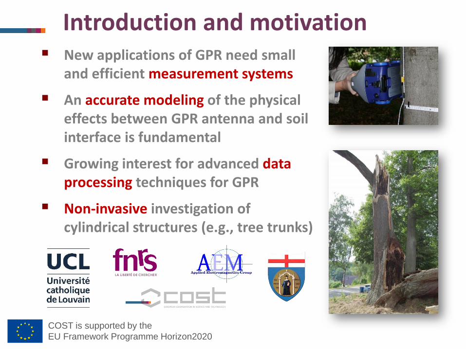
New applications of GPR need small and efficient measurement systems
An accurate modeling of the physical effects between GPR antenna and soil interface is fundamental
Growing interest for advanced data processing techniques for GPR
Non-invasive investigation of cylindrical structures (e.g., tree trunks)
Introduction and motivation
COST is supported by the
EU Framework Programme Horizon2020
Radar system design and antenna modeling
Description of the developedradar system and antenna
COST is supported by the
EU Framework Programme Horizon2020
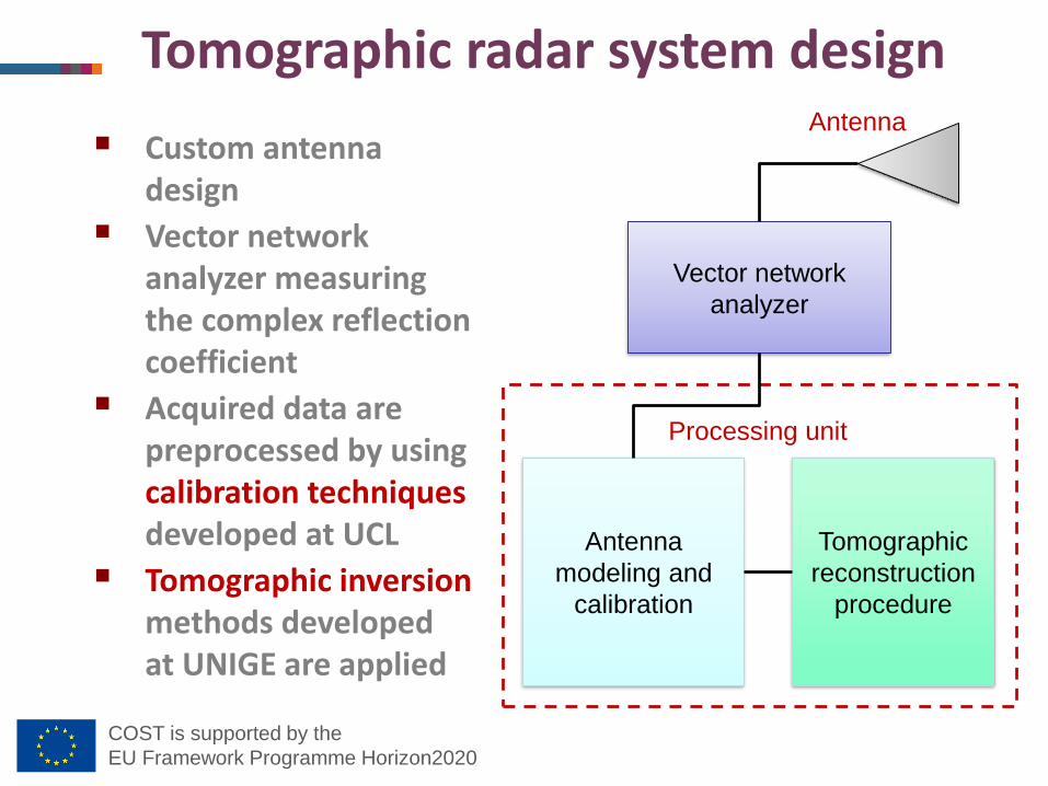
Custom antenna design
Vector network analyzer measuring the complex reflection coefficient
Acquired data are preprocessed by using calibration techniques developed at UCL
Tomographic inversion methods developed at UNIGE are applied
Tomographic radar system design
Vector network
analyzer
Antenna
modeling and
calibration
Tomographic
reconstruction
procedure
Antenna
Processing unit
COST is supported by the
EU Framework Programme Horizon2020
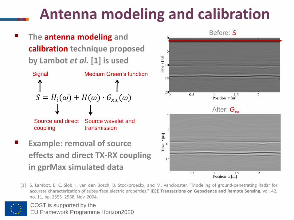
Antenna modeling and calibration
[1] S. Lambot, E. C. Slob, I. van den Bosch, B. Stockbroeckx, and M. Vanclooster, “Modeling of ground-penetrating Radar foraccurate characterization of subsurface electric properties,” IEEE Transactions on Geoscience and Remote Sensing, vol. 42,no. 11, pp. 2555–2568, Nov. 2004.
Before: S
After: Gxx
The antenna modeling and
calibration technique proposed
by Lambot et al. [1] is used
Example: removal of source
effects and direct TX-RX coupling
in gprMax simulated data
𝑆 = 𝐻𝑖(𝜔) + 𝐻(𝜔) ∙ 𝐺𝑥𝑥(𝜔)
Signal
Source and direct
coupling
Medium Green’s function
Source wavelet and
transmission
COST is supported by the
EU Framework Programme Horizon2020
Experimental results
Detection of cylindrical targets in sand box and in free space
COST is supported by the
EU Framework Programme Horizon2020
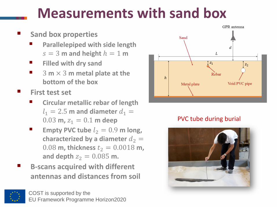
Measurements with sand box Sand box properties
Parallelepiped with side length 𝑠 = 3 m and height ℎ = 1 m
Filled with dry sand
3 m × 3 m metal plate at the bottom of the box
First test set
Circular metallic rebar of length 𝑙1 = 2.5 m and diameter 𝑑1 =0.03 m, 𝑧1 = 0.1 m deep
Empty PVC tube 𝑙2 = 0.9 m long, characterized by a diameter 𝑑2 =0.08 m, thickness 𝑡2 = 0.0018 m, and depth 𝑧2 = 0.085 m.
B-scans acquired with different antennas and distances from soil
PVC tube during burial
COST is supported by the
EU Framework Programme Horizon2020
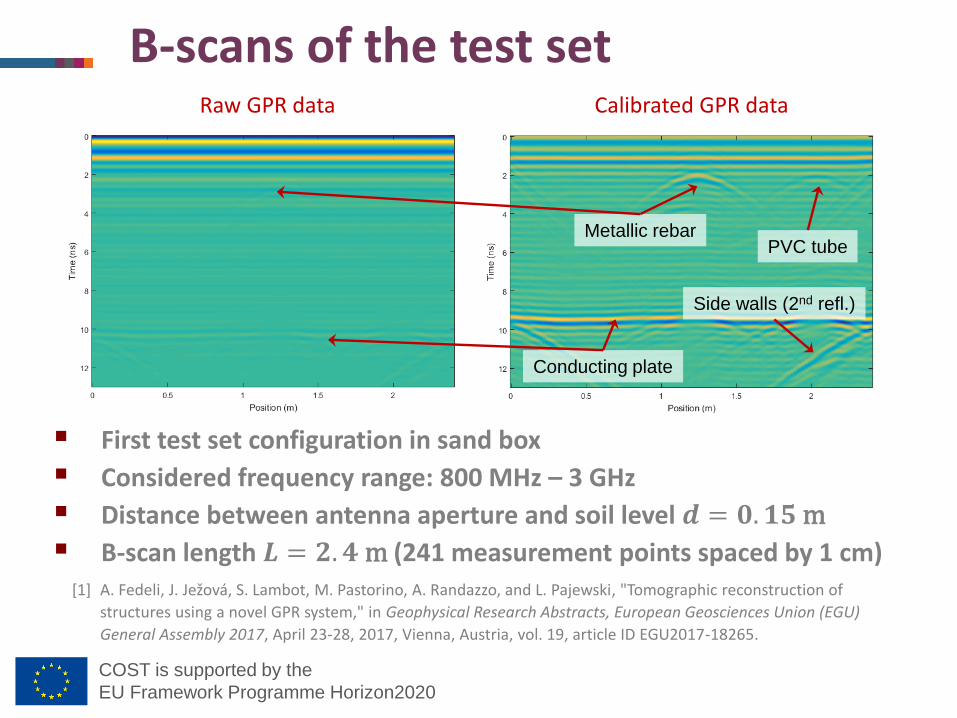
B-scans of the test set
First test set configuration in sand box
Considered frequency range: 800 MHz – 3 GHz
Distance between antenna aperture and soil level 𝒅 = 𝟎. 𝟏𝟓 m
B-scan length 𝑳 = 𝟐. 𝟒 m (241 measurement points spaced by 1 cm)
Metallic rebarPVC tube
Conducting plate
Side walls (2nd refl.)
Raw GPR data Calibrated GPR data
[1] A. Fedeli, J. Ježová, S. Lambot, M. Pastorino, A. Randazzo, and L. Pajewski, "Tomographic reconstruction of
structures using a novel GPR system," in Geophysical Research Abstracts, European Geosciences Union (EGU)
General Assembly 2017, April 23-28, 2017, Vienna, Austria, vol. 19, article ID EGU2017-18265.
COST is supported by the
EU Framework Programme Horizon2020
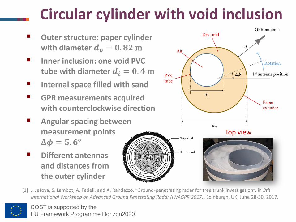
Outer structure: paper cylinder with diameter 𝒅𝒐 = 𝟎. 𝟖𝟐 m
Inner inclusion: one void PVC tube with diameter 𝒅𝒊 = 𝟎. 𝟒 m
Internal space filled with sand
GPR measurements acquired with counterclockwise direction
Angular spacing between measurement points 𝚫𝝓 = 𝟓. 𝟔°
Different antennasand distances from the outer cylinder
Circular cylinder with void inclusion
Top view
[1] J. Ježová, S. Lambot, A. Fedeli, and A. Randazzo, “Ground-penetrating radar for tree trunk investigation”, in 9th
International Workshop on Advanced Ground Penetrating Radar (IWAGPR 2017), Edinburgh, UK, June 28-30, 2017.
COST is supported by the
EU Framework Programme Horizon2020
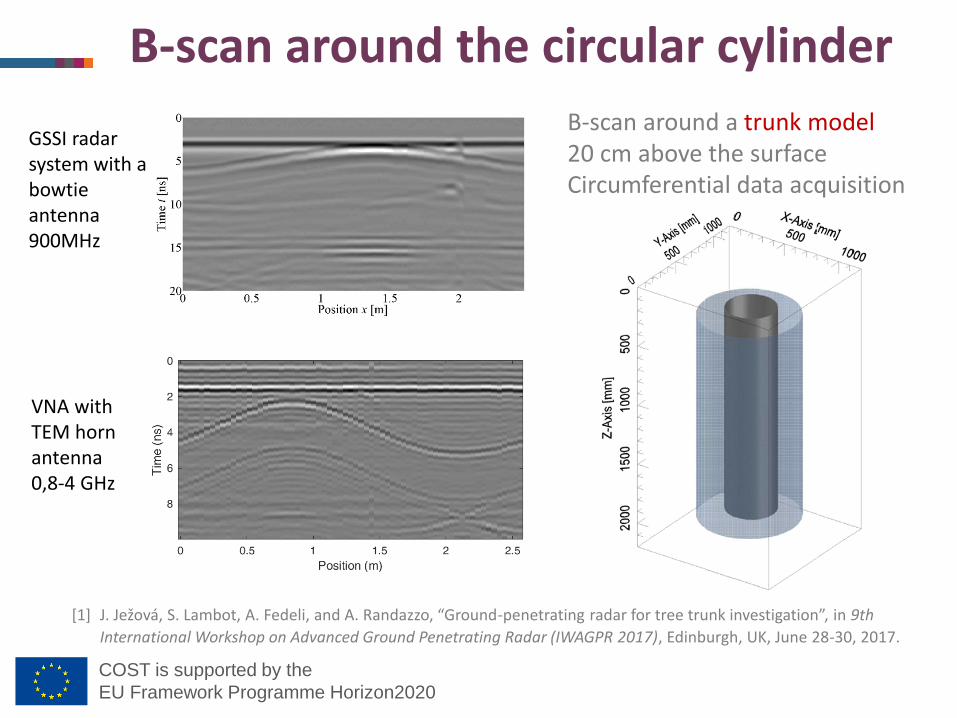
B-scan around the circular cylinder
B-scan around a trunk model20 cm above the surfaceCircumferential data acquisition
GSSI radar system with a bowtie antenna 900MHz
VNA with TEM horn antenna0,8-4 GHz
[1] J. Ježová, S. Lambot, A. Fedeli, and A. Randazzo, “Ground-penetrating radar for tree trunk investigation”, in 9th
International Workshop on Advanced Ground Penetrating Radar (IWAGPR 2017), Edinburgh, UK, June 28-30, 2017.
COST is supported by the
EU Framework Programme Horizon2020
Conclusions
Cooperation between the Georadar Research Centre at the Université catholique de Louvain and the Applied Electromagnetics Group at the University of Genoa
Experimental activities, testing different antennas and configurations of a new GPR system
Calibration of acquired data with an accurate model
Tomographic inversion
Further activities
Integration of more advanced antenna models
Full-waveform inversion


![EU Horizon2020 MSCA ITN ETN ACROSSING - ACROSSING | …ACROSSING] D1.1 - ESR... · EU Horizon2020 MSCA ITN ETN ACROSSING 01 January 2016 – 30 December 2019 Deliverable D1.1 Deliverable](https://img.pdfslide.us/doc/110x75/5ea38022152a3713a82fbed9/eu-horizon2020-msca-itn-etn-acrossing-acrossing-acrossing-d11-esr-eu.jpg)