Embed Size (px)
Citation preview
ANSYS ACT Workflow Designer (Beta)
ANSYS ACT Workflow Designer (Beta)
ii
Copyright and Trademark Information
© 2017 ANSYS, Inc. Unauthorized use, distribution or duplication is prohibited.
ANSYS, ANSYS Workbench, AUTODYN, CFX, FLUENT and any and all ANSYS, Inc. brand, product, service and feature names, logos and slogans are registered trademarks or trademarks of ANSYS, Inc. or its subsidiaries located in the United States or other countries. ICEM CFD is a trademark used by ANSYS, Inc. under license. CFX is a trademark of Sony Corporation in Japan. All other brand, product, service and feature names or trademarks are the property of their respective owners. FLEMlm and FLEXnet are trademarks of Flexera swoftware LLC.
Disclaimer Notice
THIS ANSYS SOFTWARE PRODUCT AND PROGRAM DOCUMENTATION INCLUDE TRADE SECRETS AND ARE CONFIDENTIAL AND PROPRIETARY PRODUCTS OF ANSYS, INC., ITS SUBSIDIARIES, OR LICENSORS. The software products and documentation are furnished by ANSYS, Inc., its subsidiaries, or affiliates under a software license agreement that contains provisions concerning non-disclosure, copying, length and nature of use, compliance with exporting laws, warranties, disclaimers, limitations of liability, and remedies, and other provisions. The software products and documentation may be used, disclosed, transferred, or copied only in accordance with the terms and conditions of that software license agreement.
ANSYS, Inc. and ANSYS Europe, Ltd. are UL registered ISO 9001: 2008 companies.
U.S. Government Rights
For U.S. Government users, except as specifically granted by the ANSYS, Inc. software license agreement, the use, duplication, or disclosure by the United States Government is subject to restrictions stated in the ANSYS, Inc. software license agreement and FAR 12.212 (for non-DOD licenses).
Third-Party Software
See the legal information in the product help files for the complete Legal Notice for ANSYS proprietary software and third-party software. If you are unable to access the Legal Notice, contact ANSYS, Inc.
Published in the U.S.A.
ANSYS ACT Workflow Designer (Beta)
iii
Contents
Beta Features ................................................................................................................................................ 1 Getting Started .............................................................................................................................................. 1 Workflow Designer Overview ....................................................................................................................... 1 Workflow Designer Engagement .................................................................................................................. 1 Workflow Designer Views ............................................................................................................................. 2
Toolbox View ............................................................................................................................................ 2 Adding a Task Group ............................................................................................................................. 3 Adding a Task ........................................................................................................................................ 3
Workflow Preview View ........................................................................................................................... 3 Properties View ........................................................................................................................................ 3
Workflow Actions Toolbar ............................................................................................................................ 4 Publishing a Workflow .............................................................................................................................. 5 Resetting the Workflow Preview View ..................................................................................................... 7
Published Workflows .................................................................................................................................... 7 Application Properties .............................................................................................................................. 8
Target Executable ................................................................................................................................. 8 Target Executable Directory.................................................................................................................. 8 Command Line Arguments ................................................................................................................... 9
Input Specifications .................................................................................................................................. 9 Input Files .............................................................................................................................................. 9 Input Parameters ................................................................................................................................ 10
Output Specifications ............................................................................................................................. 10 Output Files ......................................................................................................................................... 11 Output Parameters ............................................................................................................................. 11
Example ....................................................................................................................................................... 12 Application Background.......................................................................................................................... 12 Process .................................................................................................................................................... 12
ANSYS ACT Workflow Designer (Beta)
1
Beta Features Beta features have not been fully tested and validated. ANSYS, Inc. may, at its discretion, fully release, change, or withdraw beta features in future revisions. It makes no commitment to doing so on any particular schedule. ANSYS, Inc. makes no commitment to resolve defects reported against beta features. However, your feedback will help us improve the quality of the product.
Beta features are not subject to the ANSYS Class 3 error reporting system. ANSYS, Inc. does not guarantee that input files used with beta features will run successfully from version to version of the software, nor with the final released version of the features. You may need to modify the input files before running them on other versions.
To enable beta features in Workbench, select Tools > Options > Appearance and then select the Beta Options check box.
Getting Started This document provides information about using the beta release of the ANSYS ACT Workflow Designer.
The new Workflow Designer makes creating customized workflows easy, transforming the creation of a task group and tasks into a quick and interactive process.
To use the Workflow Designer in ANSYS 19.0, you must enable beta options in the Workbench Options dialog box. Simply select Tools > Options > Appearance and then the Beta Options check box under the Display heading.
Workflow Designer Overview Since 17.2, ACT has supported ANSYS Workbench extensibility with custom workflows. ACT custom tasks and task groups introduce external applications to Workbench’s drag-and-drop simulation environment.
While you can still manually create ACT workflows and extensions, you can choose to use the Workflow Designer instead. This lightweight integration automates workflow setup, relieving the burden of creating an ACT extension from scratch.
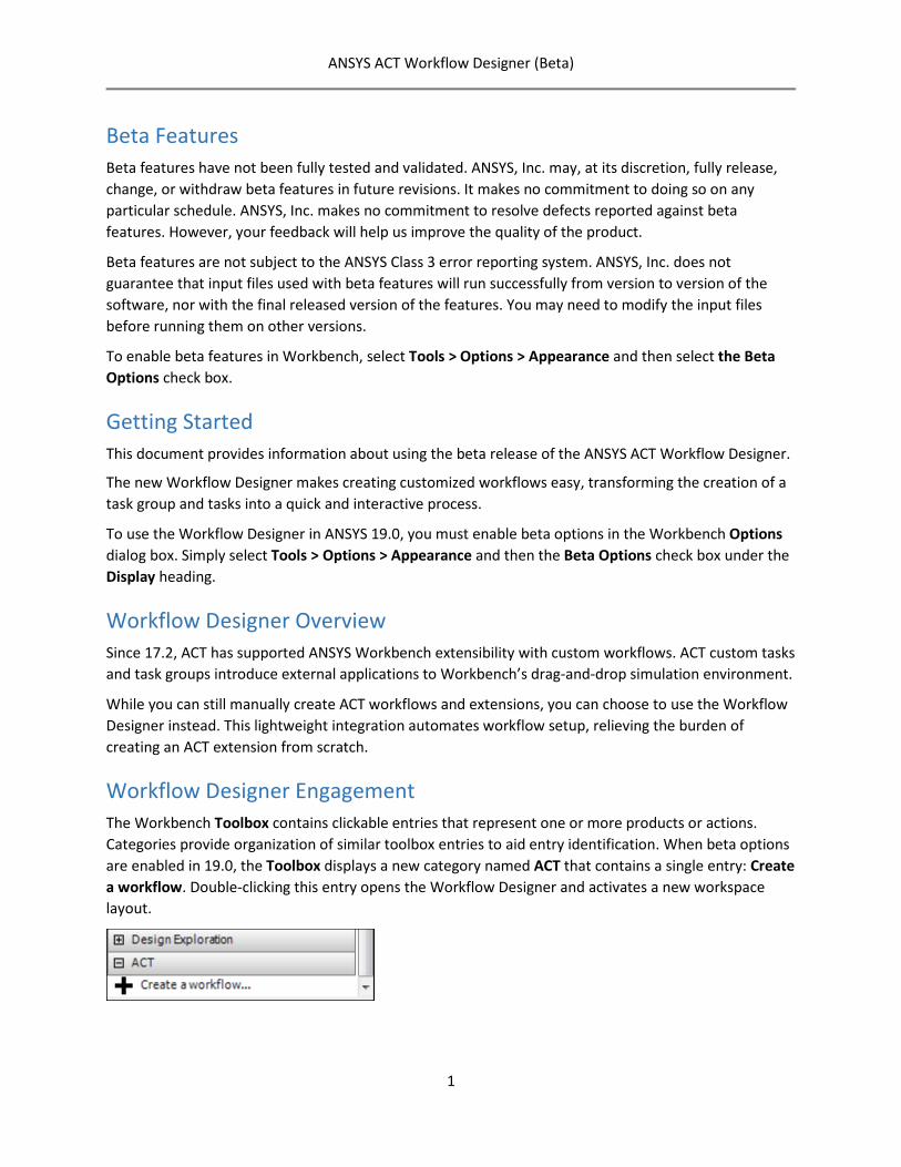
Workflow Designer Engagement The Workbench Toolbox contains clickable entries that represent one or more products or actions. Categories provide organization of similar toolbox entries to aid entry identification. When beta options are enabled in 19.0, the Toolbox displays a new category named ACT that contains a single entry: Create a workflow. Double-clicking this entry opens the Workflow Designer and activates a new workspace layout.
ANSYS ACT Workflow Designer (Beta)
2
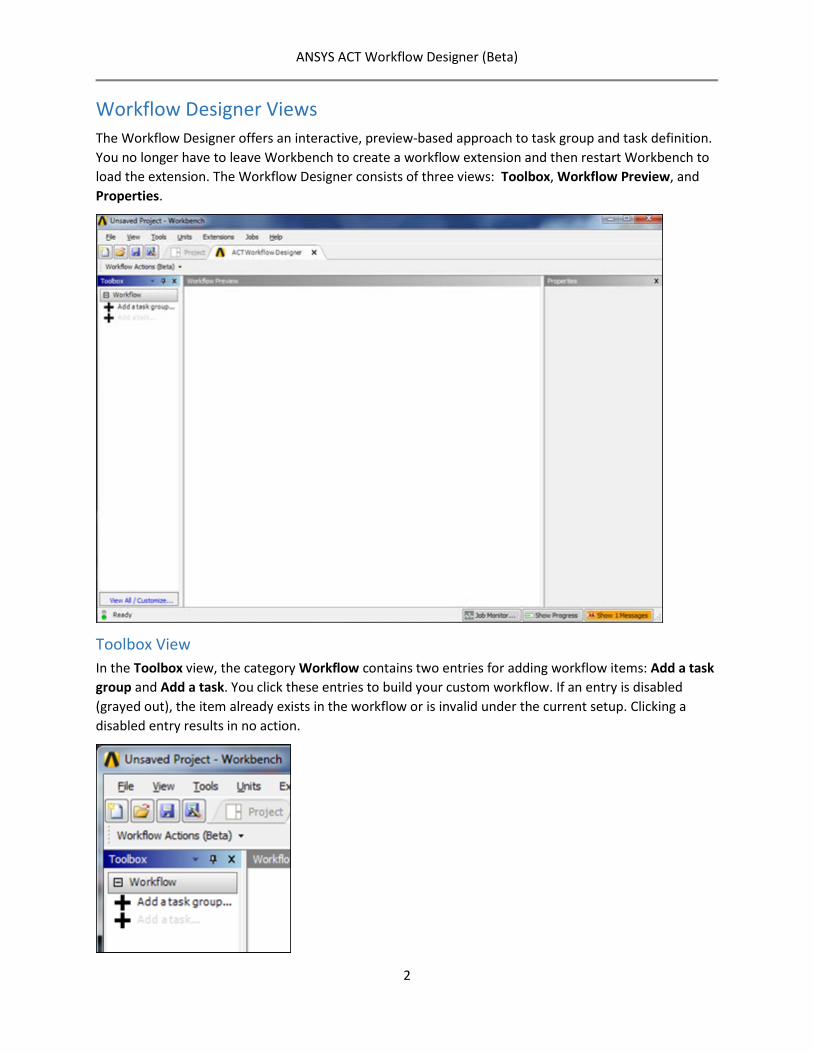
Workflow Designer Views The Workflow Designer offers an interactive, preview-based approach to task group and task definition. You no longer have to leave Workbench to create a workflow extension and then restart Workbench to load the extension. The Workflow Designer consists of three views: Toolbox, Workflow Preview, and Properties.
Toolbox View In the Toolbox view, the category Workflow contains two entries for adding workflow items: Add a task group and Add a task. You click these entries to build your custom workflow. If an entry is disabled (grayed out), the item already exists in the workflow or is invalid under the current setup. Clicking a disabled entry results in no action.
ANSYS ACT Workflow Designer (Beta)
3
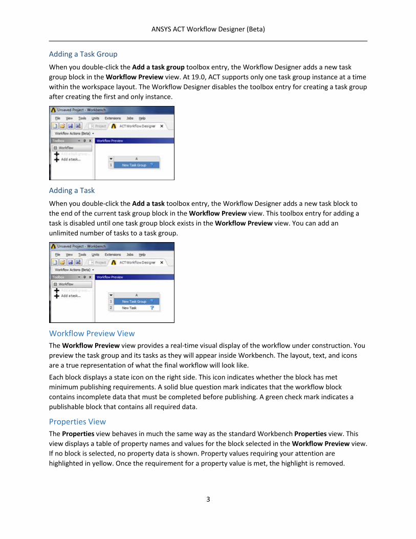
Adding a Task Group When you double-click the Add a task group toolbox entry, the Workflow Designer adds a new task group block in the Workflow Preview view. At 19.0, ACT supports only one task group instance at a time within the workspace layout. The Workflow Designer disables the toolbox entry for creating a task group after creating the first and only instance.
Adding a Task
When you double-click the Add a task toolbox entry, the Workflow Designer adds a new task block to the end of the current task group block in the Workflow Preview view. This toolbox entry for adding a task is disabled until one task group block exists in the Workflow Preview view. You can add an unlimited number of tasks to a task group.
Workflow Preview View The Workflow Preview view provides a real-time visual display of the workflow under construction. You preview the task group and its tasks as they will appear inside Workbench. The layout, text, and icons are a true representation of what the final workflow will look like.
Each block displays a state icon on the right side. This icon indicates whether the block has met minimum publishing requirements. A solid blue question mark indicates that the workflow block contains incomplete data that must be completed before publishing. A green check mark indicates a publishable block that contains all required data.
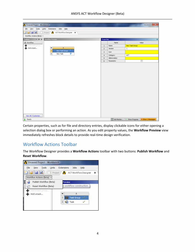
Properties View The Properties view behaves in much the same way as the standard Workbench Properties view. This view displays a table of property names and values for the block selected in the Workflow Preview view. If no block is selected, no property data is shown. Property values requiring your attention are highlighted in yellow. Once the requirement for a property value is met, the highlight is removed.
ANSYS ACT Workflow Designer (Beta)
4
Certain properties, such as for file and directory entries, display clickable icons for either opening a selection dialog box or performing an action. As you edit property values, the Workflow Preview view immediately refreshes block details to provide real-time design verification.
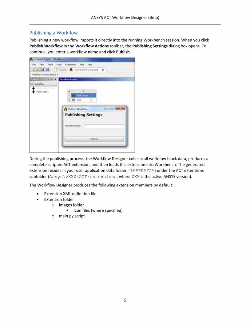
Workflow Actions Toolbar The Workflow Designer provides a Workflow Actions toolbar with two buttons: Publish Workflow and Reset Workflow.
ANSYS ACT Workflow Designer (Beta)
5
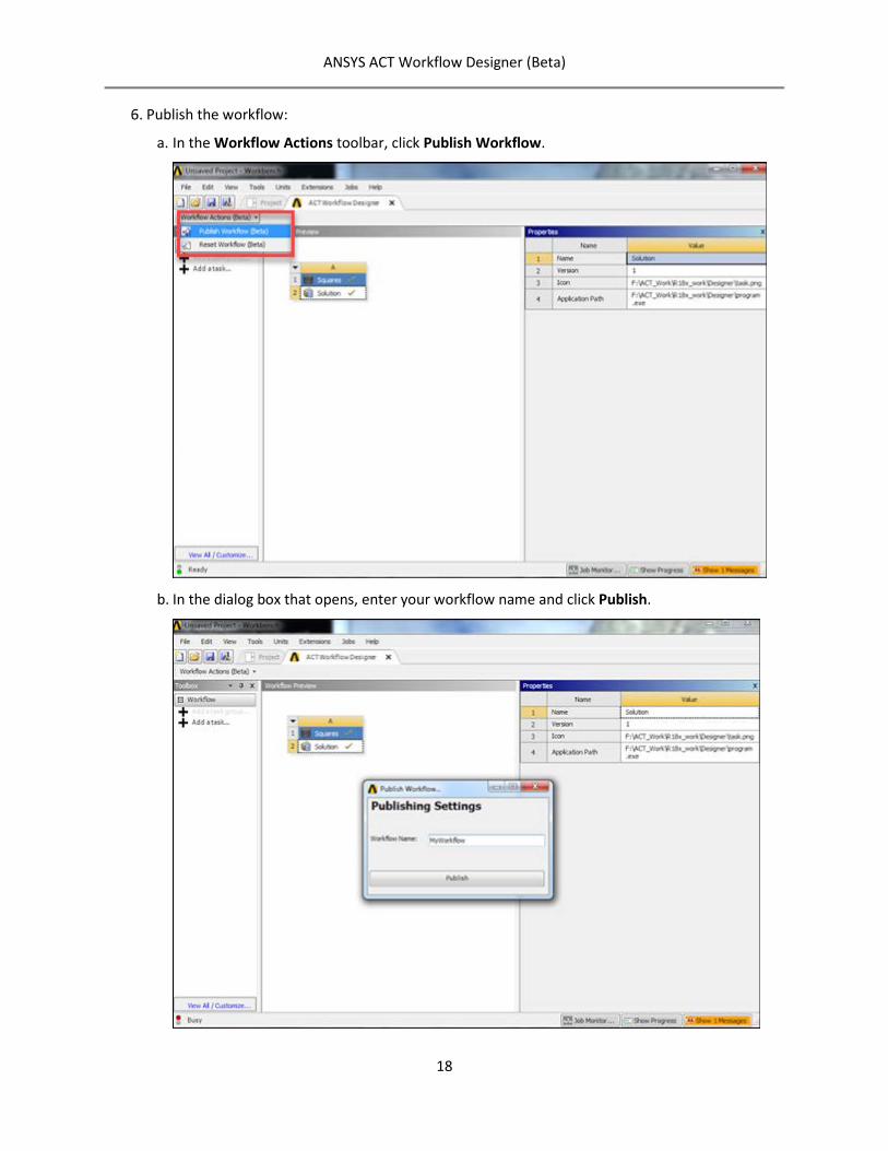
Publishing a Workflow Publishing a new workflow imports it directly into the running Workbench session. When you click Publish Workflow in the Workflow Actions toolbar, the Publishing Settings dialog box opens. To continue, you enter a workflow name and click Publish.
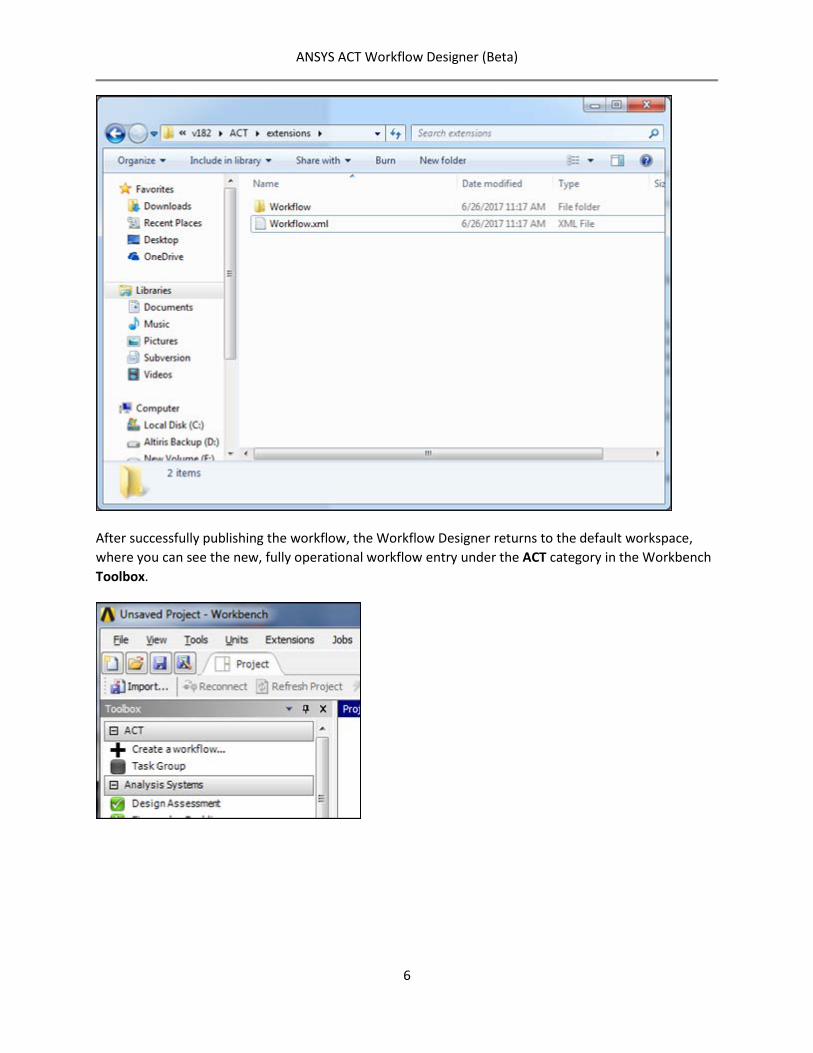
During the publishing process, the Workflow Designer collects all workflow block data, produces a complete scripted ACT extension, and then loads this extension into Workbench. The generated extension resides in your user application data folder (%APPDATA%) under the ACT extensions subfolder (Ansys\vXXX\ACT\extensions, where XXX is the active ANSYS version).
The Workflow Designer produces the following extension members by default:
• Extension XML definition file • Extension folder
o Images folder Icon files (where specified)
o main.py script
ANSYS ACT Workflow Designer (Beta)
6
After successfully publishing the workflow, the Workflow Designer returns to the default workspace, where you can see the new, fully operational workflow entry under the ACT category in the Workbench Toolbox.
ANSYS ACT Workflow Designer (Beta)
7
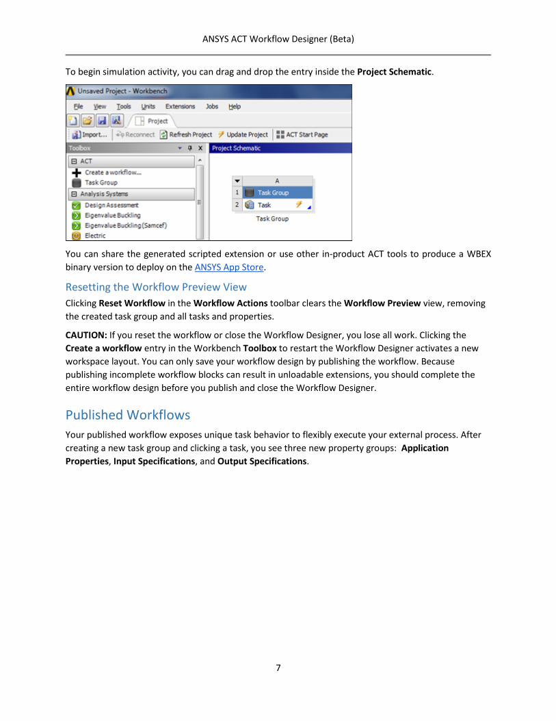
To begin simulation activity, you can drag and drop the entry inside the Project Schematic.
You can share the generated scripted extension or use other in-product ACT tools to produce a WBEX binary version to deploy on the ANSYS App Store.
Resetting the Workflow Preview View Clicking Reset Workflow in the Workflow Actions toolbar clears the Workflow Preview view, removing the created task group and all tasks and properties.
CAUTION: If you reset the workflow or close the Workflow Designer, you lose all work. Clicking the Create a workflow entry in the Workbench Toolbox to restart the Workflow Designer activates a new workspace layout. You can only save your workflow design by publishing the workflow. Because publishing incomplete workflow blocks can result in unloadable extensions, you should complete the entire workflow design before you publish and close the Workflow Designer.
Published Workflows Your published workflow exposes unique task behavior to flexibly execute your external process. After creating a new task group and clicking a task, you see three new property groups: Application Properties, Input Specifications, and Output Specifications.
ANSYS ACT Workflow Designer (Beta)
8
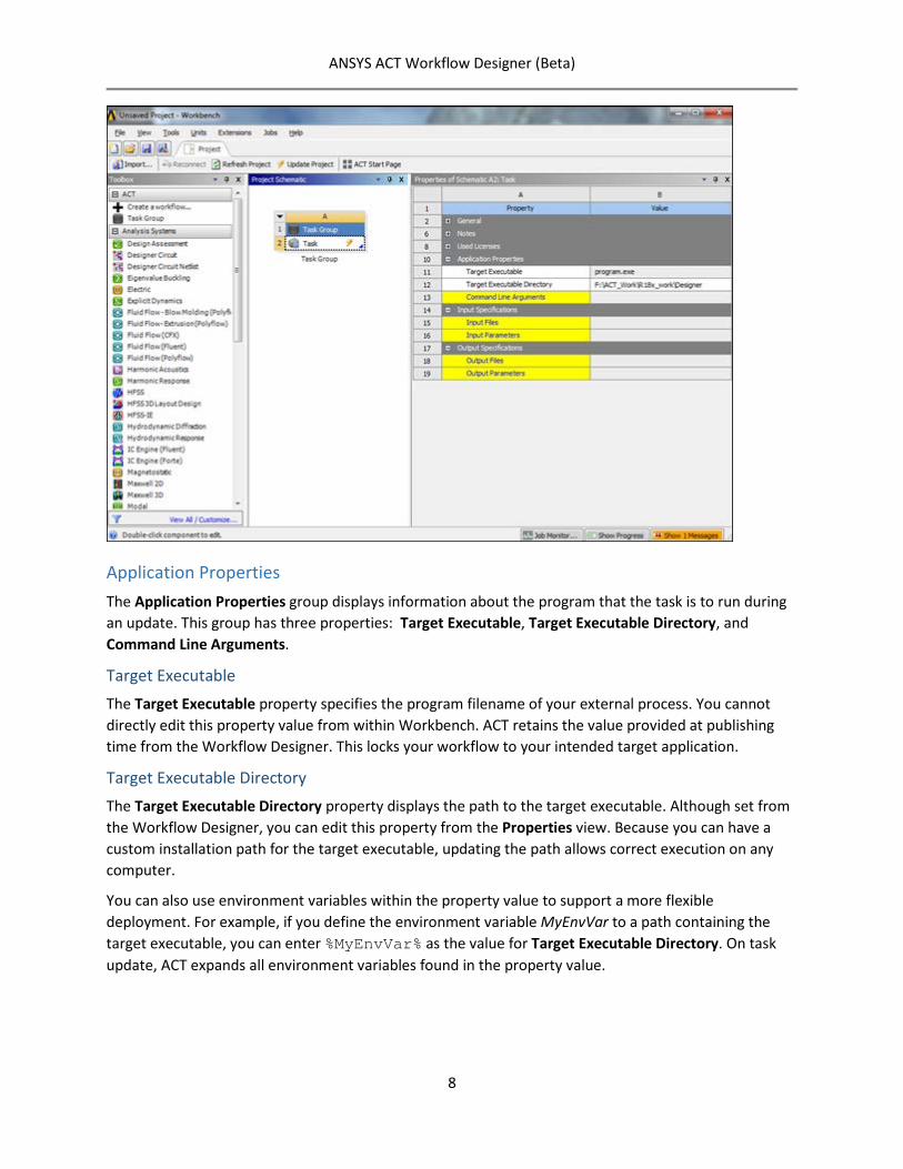
Application Properties The Application Properties group displays information about the program that the task is to run during an update. This group has three properties: Target Executable, Target Executable Directory, and Command Line Arguments.
Target Executable The Target Executable property specifies the program filename of your external process. You cannot directly edit this property value from within Workbench. ACT retains the value provided at publishing time from the Workflow Designer. This locks your workflow to your intended target application.
Target Executable Directory The Target Executable Directory property displays the path to the target executable. Although set from the Workflow Designer, you can edit this property from the Properties view. Because you can have a custom installation path for the target executable, updating the path allows correct execution on any computer.
You can also use environment variables within the property value to support a more flexible deployment. For example, if you define the environment variable MyEnvVar to a path containing the target executable, you can enter %MyEnvVar% as the value for Target Executable Directory. On task update, ACT expands all environment variables found in the property value.
ANSYS ACT Workflow Designer (Beta)
9
Command Line Arguments The Command Line Arguments property holds values that ACT applies as command line arguments when running the target executable. Unlike standard property entries, this property is a clickable title link to enable interactive data entry.
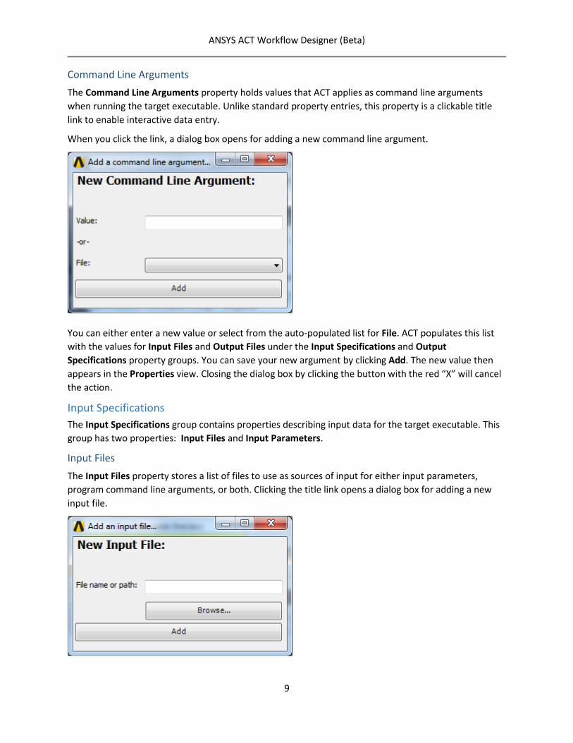
When you click the link, a dialog box opens for adding a new command line argument.
You can either enter a new value or select from the auto-populated list for File. ACT populates this list with the values for Input Files and Output Files under the Input Specifications and Output Specifications property groups. You can save your new argument by clicking Add. The new value then appears in the Properties view. Closing the dialog box by clicking the button with the red “X” will cancel the action.
Input Specifications The Input Specifications group contains properties describing input data for the target executable. This group has two properties: Input Files and Input Parameters.
Input Files The Input Files property stores a list of files to use as sources of input for either input parameters, program command line arguments, or both. Clicking the title link opens a dialog box for adding a new input file.
ANSYS ACT Workflow Designer (Beta)
10
You can enter a filename (including extension) or click Browse to navigate to and select a file. To complete the input file addition, click Add. Closing the dialog box by clicking the button with the red “X” will cancel the action.
When entering only the filename, the task creates a new file in the task’s current working directory, relative to the Workbench project. The task also prepopulates this new file with all input parameter data already supplied for the Input Parameters property. For a pre-existing file, the task copies the file to its current working directory. On successful creation or copy, the task renames the file by appending the extension .actinput to the original filename.
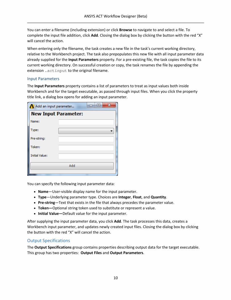
Input Parameters The Input Parameters property contains a list of parameters to treat as input values both inside Workbench and for the target executable, as passed through input files. When you click the property title link, a dialog box opens for adding an input parameter.
You can specify the following input parameter data:
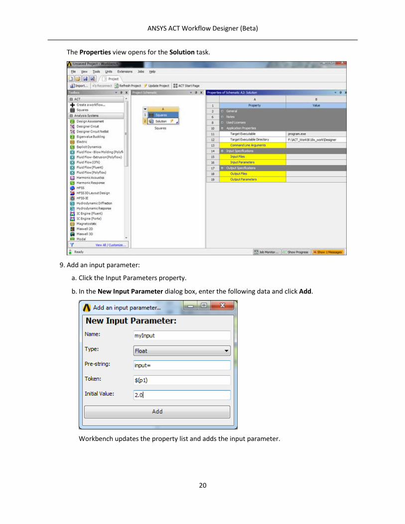
• Name—User-visible display name for the input parameter. • Type—Underlying parameter type. Choices are Integer, Float, and Quantity. • Pre-string—Text that exists in the file that always precedes the parameter value. • Token—Optional string token used to substitute or represent a value. • Initial Value—Default value for the input parameter.
After supplying the input parameter data, you click Add. The task processes this data, creates a Workbench input parameter, and updates newly created input files. Closing the dialog box by clicking the button with the red “X” will cancel the action.
Output Specifications The Output Specifications group contains properties describing output data for the target executable. This group has two properties: Output Files and Output Parameters.
ANSYS ACT Workflow Designer (Beta)
11
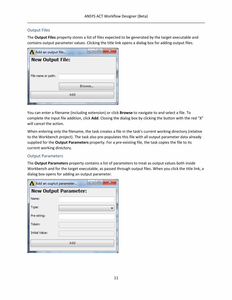
Output Files The Output Files property stores a list of files expected to be generated by the target executable and contains output parameter values. Clicking the title link opens a dialog box for adding output files.
You can enter a filename (including extension) or click Browse to navigate to and select a file. To complete the input file addition, click Add. Closing the dialog box by clicking the button with the red “X” will cancel the action.
When entering only the filename, the task creates a file in the task’s current working directory (relative to the Workbench project). The task also pre-populates this file with all output parameter data already supplied for the Output Parameters property. For a pre-existing file, the task copies the file to its current working directory.
Output Parameters The Output Parameters property contains a list of parameters to treat as output values both inside Workbench and for the target executable, as passed through output files. When you click the title link, a dialog box opens for adding an output parameter.
ANSYS ACT Workflow Designer (Beta)
12
You can specify the following output parameter data:
o Name—User-visible display name for the output parameter. o Type—Underlying parameter type. Choices are Integer, Float, and Quantity. o Pre-string—Text that exists in the file that always precedes the parameter value.
The Token and Initial Value fields are disabled when defining output parameters.
After supplying the output parameter data, you click Add. The task processes the data and create a new Workbench output parameter. Closing the dialog by clicking the button with the red “X” will cancel the action.
Example The following example steps through the workflow creation and execution process using the Workflow Designer.
Goal: Integrate a “squares” application.
Application Background The application accepts as command line arguments an input text file path and output text file path. The input file should contain a double precision number, preceded by the string input=. On reading and parsing the input value, the application computes the square of this input. The application then generates an output file to the file path specified on the command line. The output file contains the resulting value, preceded by the string output=.
Process Steps follow for integrating the “squares” application.
Start Workbench 19.0.
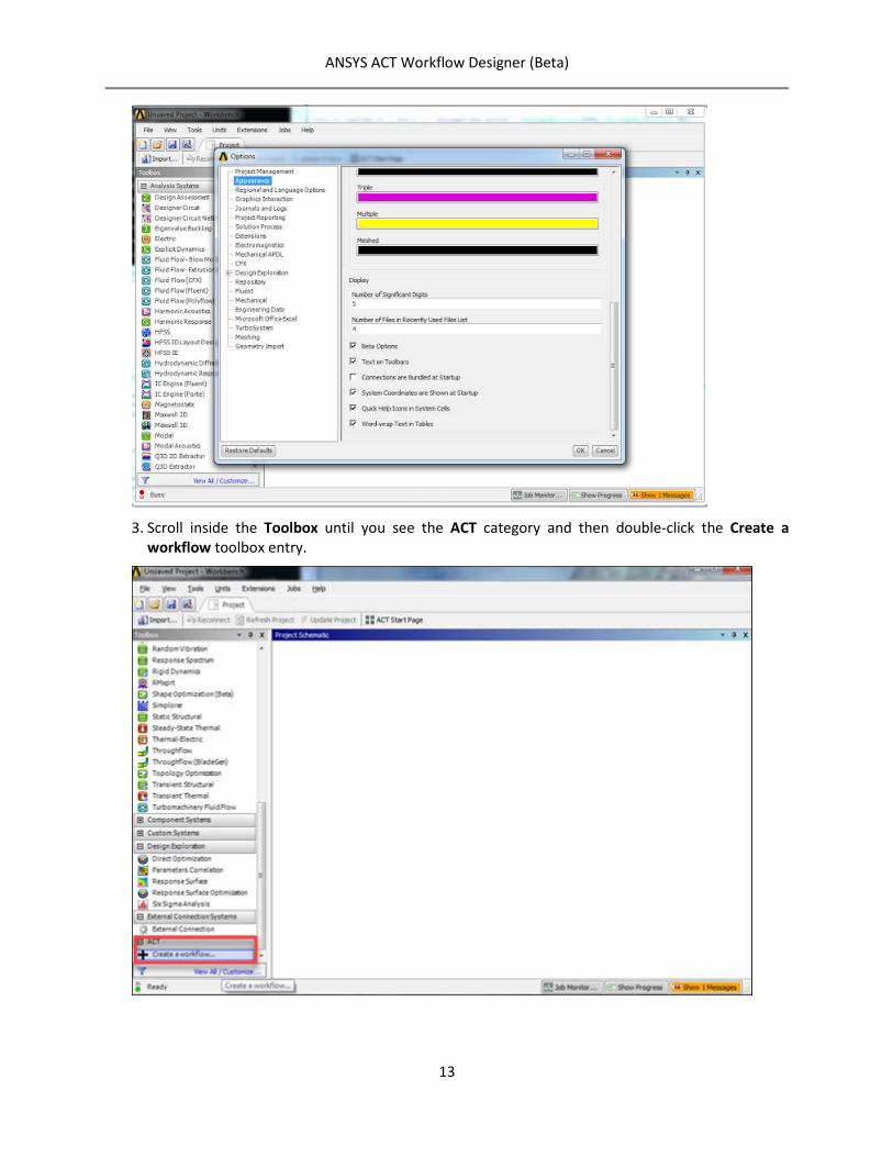
Select Tools > Options > Appearance and enable the Beta Options preference.
ANSYS ACT Workflow Designer (Beta)
13
Scroll inside the Toolbox until you see the ACT category and then double-click the Create a workflow toolbox entry.
ANSYS ACT Workflow Designer (Beta)
14
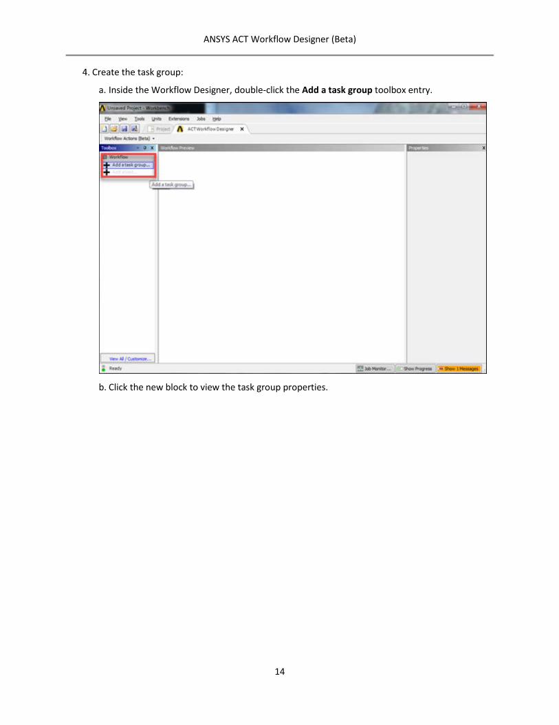
Create the task group:
a. Inside the Workflow Designer, double-click the Add a task group toolbox entry.
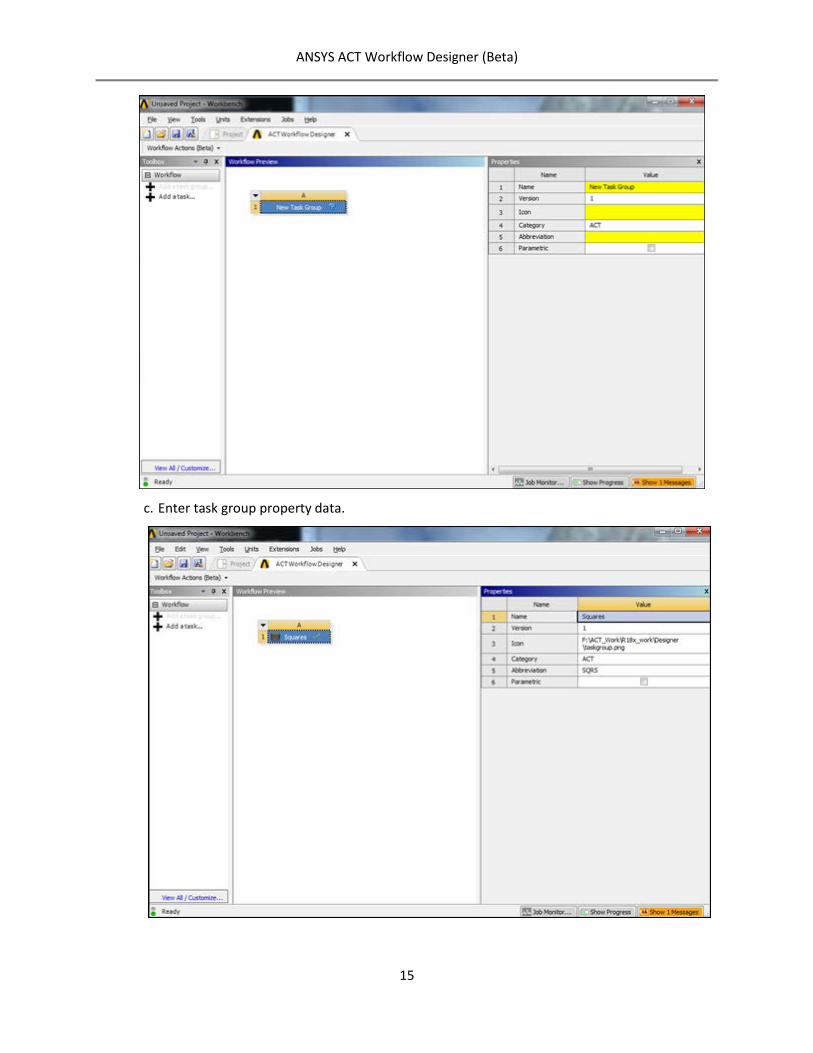
b. Click the new block to view the task group properties.
ANSYS ACT Workflow Designer (Beta)
15
c. Enter task group property data.
ANSYS ACT Workflow Designer (Beta)
16
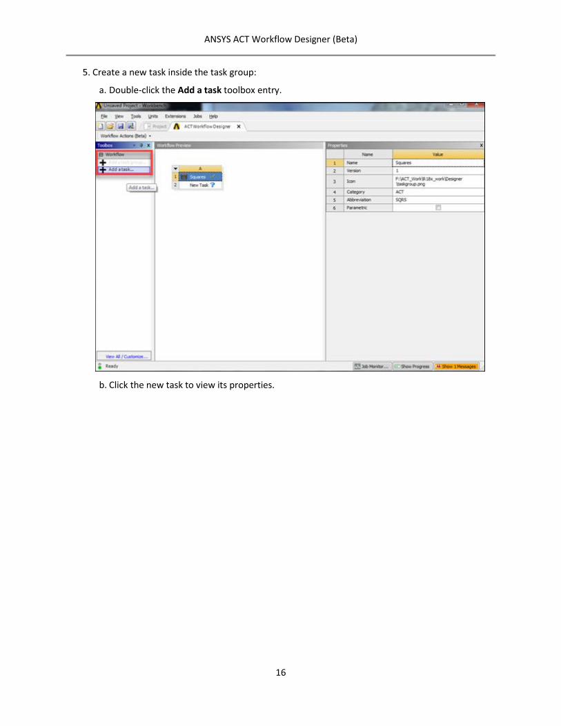
Create a new task inside the task group:
a. Double-click the Add a task toolbox entry.
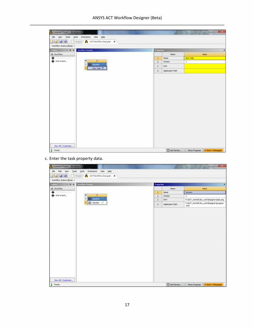
b. Click the new task to view its properties.
ANSYS ACT Workflow Designer (Beta)
17
c. Enter the task property data.
ANSYS ACT Workflow Designer (Beta)
18
Publish the workflow:
a. In the Workflow Actions toolbar, click Publish Workflow.
b. In the dialog box that opens, enter your workflow name and click Publish.
ANSYS ACT Workflow Designer (Beta)
19
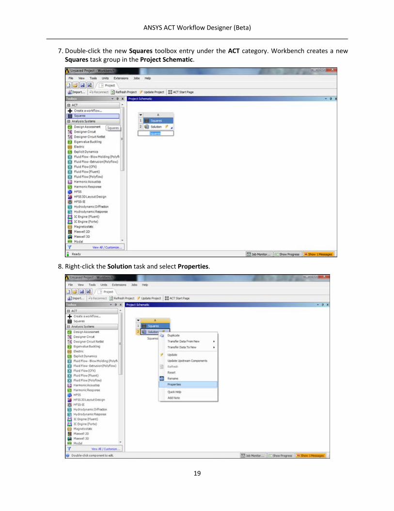
Double-click the new Squares toolbox entry under the ACT category. Workbench creates a new Squares task group in the Project Schematic.
Right-click the Solution task and select Properties.
ANSYS ACT Workflow Designer (Beta)
20
The Properties view opens for the Solution task.
Add an input parameter:
a. Click the Input Parameters property.
b. In the New Input Parameter dialog box, enter the following data and click Add.
Workbench updates the property list and adds the input parameter.
ANSYS ACT Workflow Designer (Beta)
21
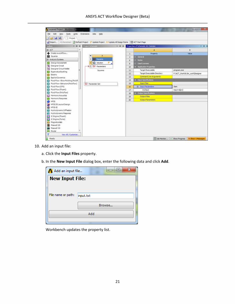
Add an input file:
a. Click the Input Files property.
b. In the New Input File dialog box, enter the following data and click Add.
Workbench updates the property list.
ANSYS ACT Workflow Designer (Beta)
22
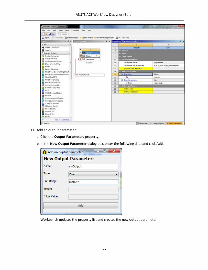
Add an output parameter:
a. Click the Output Parameters property.
b. In the New Output Parameter dialog box, enter the following data and click Add.
Workbench updates the property list and creates the new output parameter.
ANSYS ACT Workflow Designer (Beta)
23
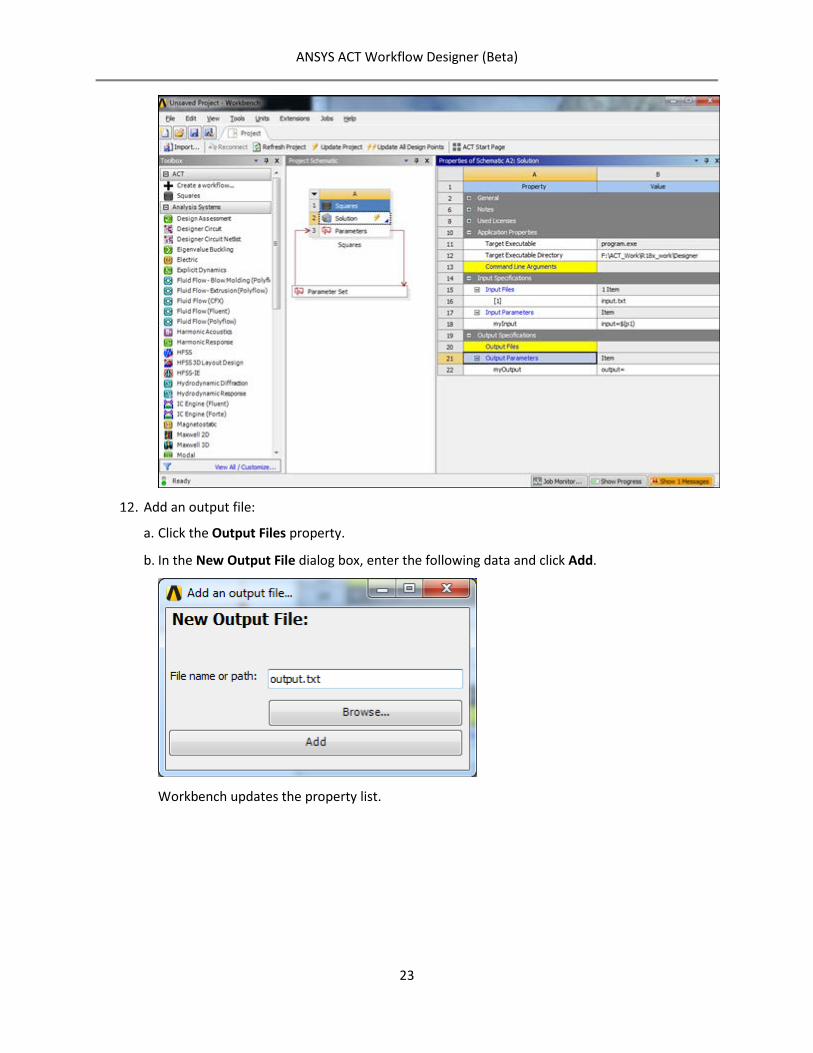
Add an output file:
a. Click the Output Files property.
b. In the New Output File dialog box, enter the following data and click Add.
Workbench updates the property list.
ANSYS ACT Workflow Designer (Beta)
24
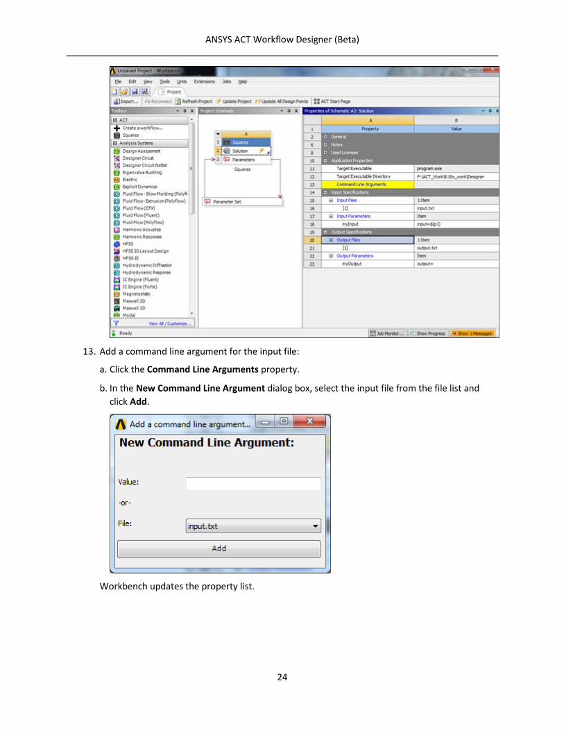
Add a command line argument for the input file:
a. Click the Command Line Arguments property.
b. In the New Command Line Argument dialog box, select the input file from the file list and click Add.
Workbench updates the property list.
ANSYS ACT Workflow Designer (Beta)
25
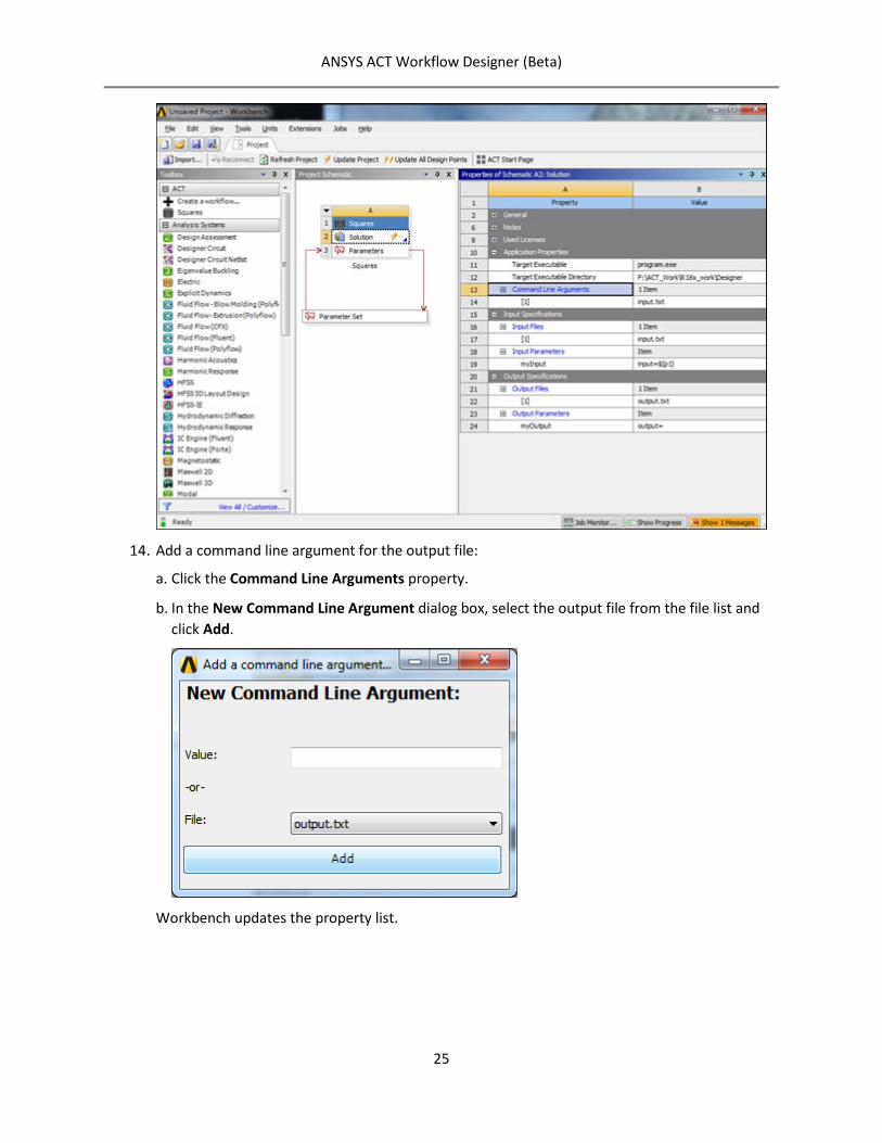
Add a command line argument for the output file:
a. Click the Command Line Arguments property.
b. In the New Command Line Argument dialog box, select the output file from the file list and click Add.
Workbench updates the property list.
ANSYS ACT Workflow Designer (Beta)
26
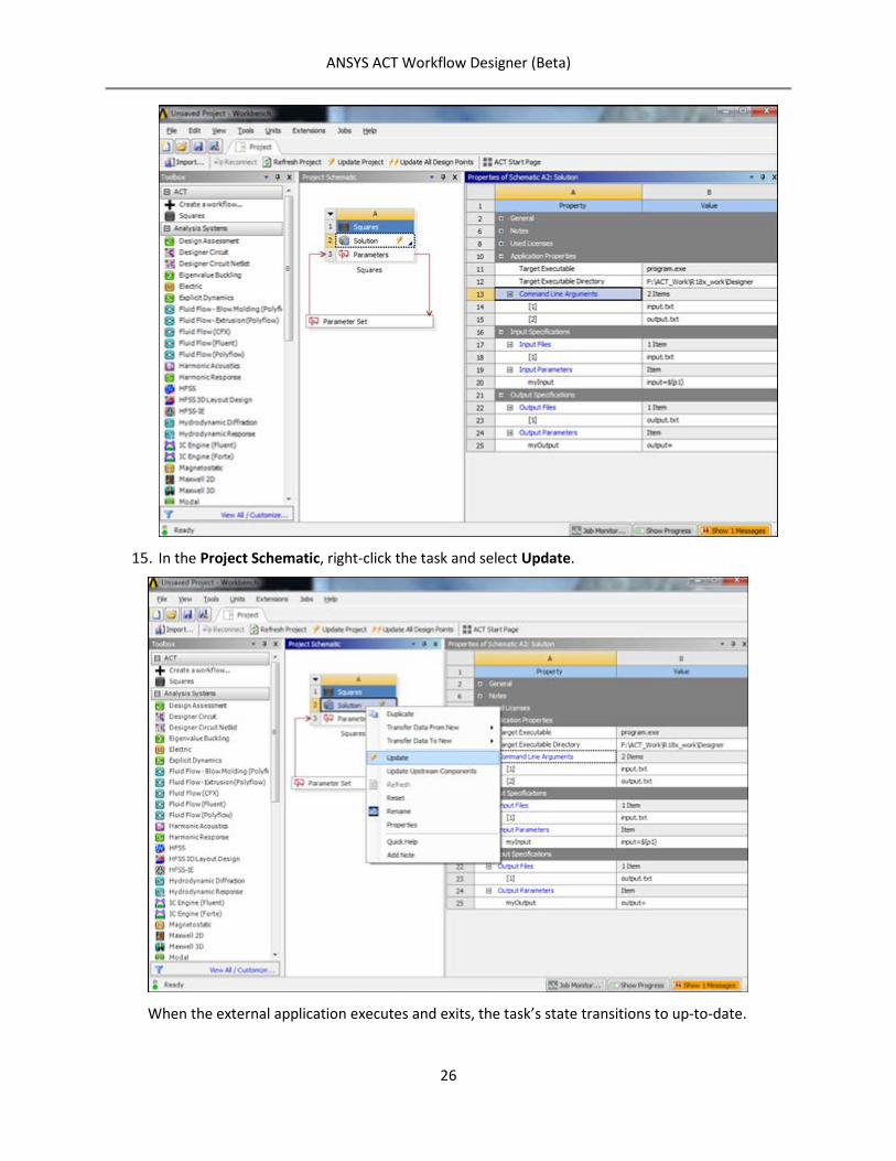
In the Project Schematic, right-click the task and select Update.
When the external application executes and exits, the task’s state transitions to up-to-date.
ANSYS ACT Workflow Designer (Beta)
27
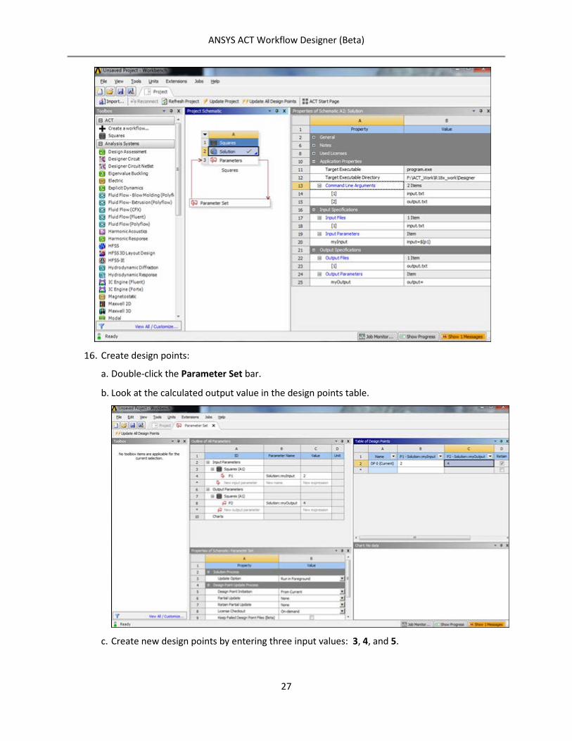
Create design points:
a. Double-click the Parameter Set bar.
b. Look at the calculated output value in the design points table.
c. Create new design points by entering three input values: 3, 4, and 5.
ANSYS ACT Workflow Designer (Beta)
28
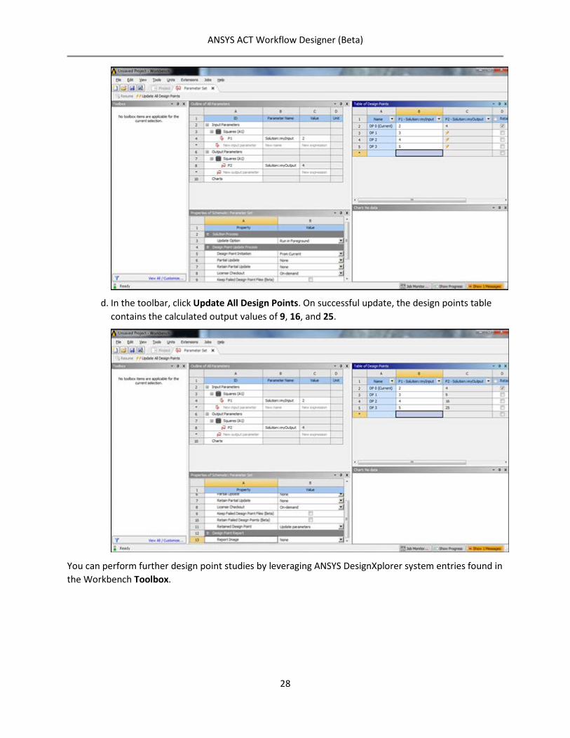
d. In the toolbar, click Update All Design Points. On successful update, the design points table contains the calculated output values of 9, 16, and 25.
You can perform further design point studies by leveraging ANSYS DesignXplorer system entries found in the Workbench Toolbox.