Embed Size (px)
Citation preview

ACS550 Users Manual 189
Embedded fieldbus
Embedded fieldbus
Overview
The ACS550 can be set up to accept control from an external system using standard
serial communication protocols. When using serial communication, the ACS550 can
either:
receive all of its control information from the fieldbus, or
be controlled from some combination of fieldbus control and other available
control locations, such as digital or analog inputs and the control panel.
Two basic serial communications configurations are available:
embedded fieldbus (EFB) Using the RS485 interface at terminals X1:2832 on
the control board, a control system can communicate with the drive using the
Modbus® protocol. (For protocol and profile descriptions, see sections Modbus
protocol technical data and ABB control profiles technical data later in this
chapter.)
fieldbus adapter (FBA) See chapter Fieldbus adapter on page 221.
Control interface
In general, the basic control interface between Modbus and the drive consists of:
Output words
Control Word
Reference1
Reference2
Input words
Status Word
Actual value 1
Actual value 2
Fieldbus
Fieldbus controller
Other devices
Connect using either:
standard embedded fieldbus (EFB) at terminals X1:2832
fieldbus adapter (FBA) module mounted in slot 2 (option Rxxx).

190 ACS550 Users Manual
Embedded fieldbus
Actual value 3
Actual value 4
Actual value 5
Actual value 6
Actual value 7
Actual value 8
The content of these words is defined by profiles. For details on the profiles used,
sees section ABB control profiles technical data on page 209.
Note: The words output and input are used as seen from the fieldbus controller
point of view. For example an output describes data flow from the fieldbus controller
to the drive and appears as an input from the drive point of view.
Planning
Network planning should address the following questions:
What types and quantities of devices must be connected to the network?
What control information must be sent down to the drives?
What feedback information must be sent from the drives to the controlling
system?
Mechanical and electrical installation EFB
WARNING! Connections should be made only while the drive is disconnected from
the power source.
Drive terminals 2832 are for RS485 communications.
Use Belden 9842 or equivalent. Belden 9842 is a dual twisted, shielded pair cable
with a wave impedance of 120 ohm.
Use one of these twisted shielded pairs for the RS485 link. Use this pair to
connect all A (-) terminals together and all B (+) terminals together.
Use one of the wires in the other pair for the logical ground (terminal 31), leaving
one wire unused.
Do not directly ground the RS485 network at any point. Ground all devices on the
network using their corresponding earthing terminals.
As always, the grounding wires should not form any closed loops, and all the
devices should be earthed to a common ground.
Connect the RS485 link in a daisy-chained bus, without dropout lines.

ACS550 Users Manual 191
Embedded fieldbus
To reduce noise on the network, terminate the RS485 network using 120 Ω
resistors at both ends of the network. Use the DIP switch to connect or disconnect
the termination resistors. See following diagram and table.
Connect the shield at each end of the cable to a drive. On one end, connect the
shield to terminal 28, and on the other end connect to terminal 32. Do not connect
the incoming and outgoing cable shields to the same terminals, as that would
make the shielding continuous.
For configuration information see the following sections:
Communication set-up EFB on page 191
Activate drive control functions EFB on page 193
The appropriate EFB protocol specific technical data. For example, Modbus
protocol technical data on page 201.
Communication set-up EFB
Serial communication selection
To activate the serial communication, set parameter 9802 COMM PROT SEL =
1 (STD MODBUS).
Note: If you cannot see the desired selection on the panel, your drive does not have
that protocol software in the application memory.
X1 Identification Hardware description
28 Screen
29 B (Positive +)
30 A (Negative -)
31 AGND
32 Screen
Terminated Terminatedstation Station Station station
28 SCR
29 B
30 A
31 AGND
32 SCR
SCR+-
GND
RS485 Multidrop application RS485 interface
Bus termination
OFF position ON positionSCR+-
GND
J2
ON
J2
ON
192 ACS550 Users Manual
Embedded fieldbus
Serial communication configuration
Setting 9802 automatically sets the appropriate default values in parameters that
define the communication process. These parameters and descriptions are defined
below. In particular, note that the station Id may require adjustment.
Note: After any changes to the communication settings, the protocol must be
reactivated by either cycling the drive power, or by clearing and then restoring the
station Id (5302).
Code DescriptionProtocol reference
Modbus
5301 EFB PROTOCOL ID
Contains the identification and program revision of the protocol.
Do not edit. Any non-zero value entered for parameter 9802 COMM PROT SEL, sets this parameter automatically. The format is: XXYY, where XX = protocol ID, and YY = program revision.
5302 EFB STATION ID
Defines the node address of the RS485 link.
Set each drive on the network with a unique value for this parameter.
When this protocol is selected, the default value for this parameter is: 1
Note: For a new address to take affect, the drive power must be cycled or 5302 must first be set to 0 before selecting a new address. Leaving 5302 = 0 places the RS485 channel in reset, disabling communication.
5303 EFB BAUD RATE
Defines the communication speed of the RS485 link in kbits per second (kbits/s).
When this protocol is selected, the default value for this parameter is: 9.6
1.2 kb/s
2.4 kb/s
4.8 kb/s
9.6 kb/s
19.2 kb/s
38.4 kb/s
57.6 kb/s
76.8 kb/s
5304 EFB PARITY
Defines the data length, parity and stop bits to be used with the RS485 communication.
The same settings must be used in all on-line stations.
0 = 8 NONE 1 8 data bits, no parity, one stop bit.1 = 8 NONE 2 8 data bits, no parity, two stop bits.2 = 8 EVEN 1 8 data bits, even parity, one stop bit.3 = 8 ODD 1 8 data bits, odd parity, one stop bit.
When this protocol is selected, the default value for this parameter is: 1
5305 EFB CTRL PROFILE
Selects the communication profile used by the EFB protocol.
0 = ABB DRV LIM Operation of Control/Status Words conforms to ABB Drives Profile, as used in ACS400.
1 = DCU PROFILE Operation of Control/Status Words conforms to 32-bit DCU Profile.
2 = ABB DRV FULL Operation of Control/Status Words conforms to ABB Drives Profile, as used in ACS600/800.
When this protocol is selected, the default value for this parameter is: 0

ACS550 Users Manual 193
Embedded fieldbus
Activate drive control functions EFB
Controlling the drive
Fieldbus control of various drive functions requires configuration to:
tell the drive to accept fieldbus control of the function
define as a fieldbus input, any drive data required for control
define as a fieldbus output, any control data required by the drive.
The following sections describe, at a general level, the configuration required for
each control function. For the protocol-specific details, see the document supplied
with the FBA module.
Start/Stop Direction control
Using the fieldbus for start/stop/direction control of the drive requires:
drive parameter values set as defined below
fieldbus controller supplied command(s) in the appropriate location. (The location
is defined by the Protocol Reference, which is protocol dependent.)
Drive parameter Value DescriptionModbus1 protocol reference
ABB DRV DCU PROFILE
1001 EXT1 COMMANDS 10 (COMM) Start/Stop by fieldbus with Ext1 selected.
40001 bits 03 40031 bits 0, 1
1002 EXT2 COMMANDS 10 (COMM) Start/Stop by fieldbus with Ext2 selected.
40001 bits 03 40031 bits 0, 1
1003 DIRECTION 3 (REQUEST) Direction by fieldbus. 4002/40032 40031 bit 3
1 For Modbus, the protocol reference can depend on the profile used, hence two columns in these tables. One column refers to the ABB Drives profile, selected when parameter 5305 = 0 (ABB DRV LIM) or 5305 = 2 (ABB DRV FULL). The other column refers to the DCU profile selected when parameter 5305 = 1 (DCU PROFILE). See section ABB control profiles technical data on page 209.
2 The reference provides direction control a negative reference provides reverse rotation.

194 ACS550 Users Manual
Embedded fieldbus
Input reference select
Using the fieldbus to provide input references to the drive requires:
drive parameter values set as defined below
fieldbus controller supplied reference word(s) in the appropriate location. (The
location is defined by the Protocol Reference, which is protocol dependent.)
Reference Scaling
Where required, REFERENCES can be scaled. See the following, as appropriate:
Modbus Register 40002 in section Modbus protocol technical data on page 201
Reference scaling in section ABB control profiles technical data on page 209.
Miscellaneous drive control
Using the fieldbus for miscellaneous drive control requires:
drive parameter values set as defined below
fieldbus controller supplied command(s) in the appropriate location. (The location
is defined by the Protocol Reference, which is protocol dependent.)
Drive parameter Value Description
Modbus protocol reference
ABB DRV DCU PROFILE
1102 EXT1/EXT2 SEL 8 (COMM) Reference set selection by fieldbus. 40001 bit 11 40031 bit 5
1103 REF1 SELECT 8 (COMM) Input reference 1 by fieldbus. 40002
1106 REF2 SELECT 8 (COMM) Input reference 2 by fieldbus. 40003
Drive parameter Value Description
Modbus protocol reference
ABB DRV DCU PROFILE
1601 RUN ENABLE 7 (COMM) Run enable by fieldbus. 40001 bit 3 40031 bit 6(inverted)
1604 FAULT RESET SEL 8 (COMM) Fault reset by fieldbus. 40001 bit 7 40031 bit 4
1606 LOCAL LOCK 8 (COMM) Source for local lock selection is the fieldbus.
Does not apply
40031 bit 14
1607 PARAM SAVE 1 (SAVE) Saves altered parameters to memory (then value returns to 0).
41607
1608 START ENABLE 1 7 (COMM) Source for start enable 1 is the fieldbus Command word.
Does not apply.
40032 bit 2
1609 START ENABLE 2 7 (COMM) Source for start enable 2 is the fieldbus Command word.
40032 bit 3
2013 MIN TORQUE SEL 7 (COMM) Source for minimum torque selection is the fieldbus.
40031 bit 15
2014 MAX TORQUE SEL 7 (COMM) Source for maximum torque selection is the fieldbus.
2201 ACC/DEC 1/2 SEL 7 (COMM) Source for ramp pair selection is the fieldbus.
40031 bit 10

ACS550 Users Manual 195
Embedded fieldbus
Relay output control
Using the fieldbus for relay output control requires:
drive parameter values set as defined below
fieldbus controller supplied, binary coded, relay command(s) in the appropriate
location. (The location is defined by the Protocol Reference, which is protocol
dependent.)
Note: Relay status feedback occurs without configuration as defined below.
Analog output control
Using the fieldbus for analog output control (e.g. PID setpoint) requires:
drive parameter values set as defined below
fieldbus controller supplied analog value(s) in the appropriate location. (The
location is defined by the Protocol Reference, which is protocol dependent.)
Drive parameter Value DescriptionModbus protocol reference
ABB DRV DCU PROFILE
1401 RELAY OUTPUT 1 35 (COMM) Relay Output 1 controlled by fieldbus.
40134 bit 0 or 00033
1402 RELAY OUTPUT 2 35 (COMM) Relay Output 2 controlled by fieldbus.
40134 bit 1 or 00034
1403 RELAY OUTPUT 3 35 (COMM) Relay Output 3 controlled by fieldbus.
40134 bit 2 or 00035
14101RELAY OUTPUT 4 35 (COMM) Relay Output 4 controlled
by fieldbus.40134 bit 3 or 00036
14111RELAY OUTPUT 5 35 (COMM) Relay Output 5 controlled
by fieldbus.40134 bit 4 or 00037
14121RELAY OUTPUT 6 35 (COMM) Relay Output 6 controlled
by fieldbus.40134 bit 5 or 00038
1 More than 3 relays requires the addition of a relay extension module.
Drive parameter Description
Modbus protocol reference
ABB DRV DCU PROFILE
0122 RO 1-3 STATUS Relay 13 status. 40122
0123 RO 4-6 STATUS Relay 46 status. 40123
Drive parameter Value Description
Modbus protocol reference
ABB DRV DCU PROFILE
1501 AO1 CONTENT SEL 135 (COMM VALUE 1) Analog Output 1 controlled by writing to parameter 0135.
0135 COMM VALUE 1 40135
1507 AO2 CONTENT SEL 136 (COMM VALUE 2) Analog Output 2 controlled by writing to parameter 0136.
0136 COMM VALUE 2 40136

196 ACS550 Users Manual
Embedded fieldbus
PID control setpoint source
Using the following settings to select the fieldbus as the setpoint source for PID
loops:
Communication fault
When using fieldbus control, specify the drives action if serial communication is lost.
Drive parameter Value Description
Modbus protocol reference
ABB DRV DCU PROFILE
4010 SET POINT SEL (Set 1)
8 (COMM VALUE 1)
9 (COMM+AI1)
10 (COMM*AI1)
Setpoint is input reference 2 (+/-/* AI1)
40003
4110 SET POINT SEL (Set 2)
4210 SET POINT SEL (Ext/Trim)
Drive parameter Value Description
3018 COMM FAULT FUNC 0 (NOT SEL)1 (FAULT)2 (CONST SP7)3 (LAST SPEED)
Set for appropriate drive response.
3019 COMM FAULT TIME Set time delay before acting on a communication loss.

ACS550 Users Manual 197
Embedded fieldbus
Feedback from the drive EFB
Pre-defined feedback
Inputs to the controller (drive outputs) have pre-defined meanings established by the
protocol. This feedback does not require drive configuration. The following table lists
a sample of feedback data. For a complete listing, see input word/point/object
listings in the technical data for the appropriate protocol starting on page 201.
Note: With Modbus, any parameter can be accessed using the format: 4 followed
by the parameter number.
Actual value scaling
The scaling of actual values can be protocol dependent. In general, for Actual
Values, scale the feedback integer using the parameters resolution. (See section
Complete parameter list on page 85 for parameter resolutions.) For example:
Where parameters are in percent, the Complete parameter descriptions section
specifies what parameter corresponds to 100%. In such cases, to convert from
percent to engineering units, multiply by the value of the parameter that defines
100% and divide by 100%.
Drive parameterModbus protocol reference
ABB DRV DCU PROFILE
0102 SPEED 40102
0103 OUTPUT FREQ 40103
0104 CURRENT 40104
0105 TORQUE 40105
0106 POWER 40106
0107 DC BUS VOLTAGE 40107
0109 OUTPUT VOLTAGE 40109
0301 FB CMD WORD1 bit 0 (STOP) 40301 bit 0
0301 FB CMD WORD1 1 bit 2 (REV) 40301 bit 2
0118 DI 1-3 STATUS bit 0 (DI3) 40118
Feedback integer
Parameter resolution
(Feedback integer) · (Parameter resolution) = Scaled value
1 0.1 mA 1 · 0.1 mA = 0.1 mA
10 0.1% 10 · 0.1% = 1%
198 ACS550 Users Manual
Embedded fieldbus
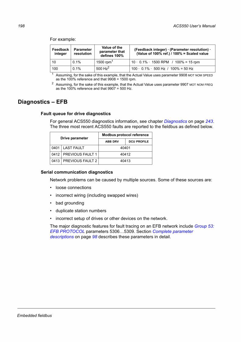
For example:
Diagnostics EFB
Fault queue for drive diagnostics
For general ACS550 diagnostics information, see chapter Diagnostics on page 243.
The three most recent ACS550 faults are reported to the fieldbus as defined below.
Serial communication diagnostics
Network problems can be caused by multiple sources. Some of these sources are:
loose connections
incorrect wiring (including swapped wires)
bad grounding
duplicate station numbers
incorrect setup of drives or other devices on the network.
The major diagnostic features for fault tracing on an EFB network include Group 53:
EFB PROTOCOL parameters 53065309. Section Complete parameter
descriptions on page 98 describes these parameters in detail.
Feedback integer
Parameter resolution
Value of the parameter that defines 100%
(Feedback integer) · (Parameter resolution) · (Value of 100% ref.) / 100% = Scaled value
10 0.1% 1500 rpm1 10 · 0.1% · 1500 RPM / 100% = 15 rpm
100 0.1% 500 Hz2 100 · 0.1% · 500 Hz / 100% = 50 Hz
1 Assuming, for the sake of this example, that the Actual Value uses parameter 9908 MOT NOM SPEED as the 100% reference and that 9908 = 1500 rpm.
2 Assuming, for the sake of this example, that the Actual Value uses parameter 9907 MOT NOM FREQ as the 100% reference and that 9907 = 500 Hz.
Drive parameterModbus protocol reference
ABB DRV DCU PROFILE
0401 LAST FAULT 40401
0412 PREVIOUS FAULT 1 40412
0413 PREVIOUS FAULT 2 40413

ACS550 Users Manual 199
Embedded fieldbus
Diagnostic situations
The sub-sections below describe various diagnostic situations the problem
symptoms and corrective actions.
Normal operation
During normal network operation, 53065309 parameter values act as follows at
each drive:
5306 EFB OK MESSAGES advances (advances for each message properly received
and addressed to this drive).
5307 EFB CRC ERRORS does not advance at all (advances when an invalid
message CRC is received).
5308 EFB UART ERRORS does not advance at all (advances when character format
errors are detected, such as parity or framing errors).
5309 EFB STATUS value varies depending on network traffic.
Loss of communication
The ACS550 behavior, if communication is lost, was configured earlier in section
Communication fault on page 196. The parameters are 3018 COMM FAULT FUNC and
3019 COMM FAULT TIME. Section Complete parameter descriptions on page 98
describes these parameters in detail.
No master station on line
If no master station is on line: Neither the EFB OK MESSAGES nor the errors (5307 EFB
CRC ERRORS and 5308 EFB UART ERRORS) increase on any of the stations.
To correct:
Check that a network master is connected and properly programmed on the
network.
Verify that the cable is connected and that it is not cut or short circuited.
Duplicate stations
If two or more stations have duplicate numbers:
Two or more drives cannot be addressed.
Every time there is a read or write to one particular station, the value for 5307 EFB
CRC ERRORS or 5308 EFB UART ERRORS advances.
To correct: Verify the station numbers of all stations. Change conflicting station
numbers.
Swapped wires
If the communication wires are swapped (terminal A on one drive is connected to
terminal B on another):
The value of 5306 EFB OK MESSAGES does not advance.
The values of 5307 EFB CRC ERRORS and 5308 EFB UART ERRORS are advancing.
To correct: Check that the RS-485 lines are not swapped.

200 ACS550 Users Manual
Embedded fieldbus
Fault 28 Serial 1 Err
If the drives control panel shows fault code 28, SERIAL 1 ERR, check for either of the
following:
The master system is down. To correct, resolve problem with master system.
The communication connection is bad. To correct, check communication
connection at the drive.
The time-out selection for the drive is too short for the given installation. The
master is not polling the drive within the specified time-out delay. To correct,
increase the time set by parameter 3019 COMM FAULT TIME.
Faults 3133 EFB1EFB3
The three EFB fault codes listed for the drive in chapter Diagnostics on page 243
(fault codes 3133) are not used.
Intermittent off-line occurrences
The problems described above are the most common problems encountered with
ACS550 serial communication. Intermittent problems might also be caused by:
marginally loose connections
wear on wires caused by equipment vibrations
insufficient grounding and shielding on both the devices and on the
communication cables.

ACS550 Users Manual 201
Embedded fieldbus
Modbus protocol technical data
Overview
The Modbus® protocol was introduced by Modicon, Inc. for use in control
environments featuring Modicon programmable controllers. Due to its ease of use
and implementation, this common PLC language was quickly adopted as a de-facto
standard for integration of a wide variety of master controllers and slave devices.
Modbus is a serial, asynchronous protocol. Transactions are half-duplex, featuring a
single Master controlling one or more Slaves. While RS232 can be used for point-to-
point communication between a single Master and a single Slave, a more common
implementation features a multi-drop RS485 network with a single Master controlling
multiple Slaves. The ACS550 features RS485 for its Modbus physical interface.
RTU
The Modbus specification defines two distinct transmission modes: ASCII and RTU.
The ACS550 supports RTU only.
Feature summary
The following Modbus function codes are supported by the ACS550.
Function Code (Hex) Description
Read Coil Status 0x01 Read discrete output status. For the ACS550, the individual bits of the control word are mapped to Coils 116. Relay outputs are mapped sequentially beginning with Coil 33 (e.g. RO1=Coil 33).
Read Discrete Input Status
0x02 Read discrete inputs status. For the ACS550, the individual bits of the status word are mapped to Inputs 116 or 132, depending on the active profile. Terminal inputs are mapped sequentially beginning with Input 33 (e.g. DI1=Input 33).
Read Multiple Holding Registers
0x03 Read multiple holding registers. For the ACS550, the entire parameter set is mapped as holding registers, as well as command, status and reference values.
Read Multiple Input Registers
0x04 Read multiple input registers. For the ACS550, the 2 analog input channels are mapped as input registers 1 & 2.
Force Single Coil 0x05 Write a single discrete output. For the ACS550, the individual bits of the control word are mapped to Coils 116. Relay outputs are mapped sequentially beginning with Coil 33 (e.g. RO1=Coil 33).
Write Single Holding Register
0x06 Write single holding register. For the ACS550, the entire parameter set is mapped as holding registers, as well as command, status and reference values.
Diagnostics 0x08 Perform Modbus diagnostics. Subcodes for Query (0x00), Restart (0x01) & Listen Only (0x04) are supported.
Force Multiple Coils 0x0F Write multiple discrete outputs. For the ACS550, the individual bits of the control word are mapped to Coils 116. Relay outputs are mapped sequentially beginning with Coil 33 (e.g. RO1=Coil 33).
Write Multiple Holding Registers
0x10 Write multiple holding registers. For the ACS550, the entire parameter set is mapped as holding registers, as well as command, status and reference values.
Read/Write Multiple Holding Registers
0x17 This function combines functions 0x03 and 0x10 into a single command.
202 ACS550 Users Manual
Embedded fieldbus
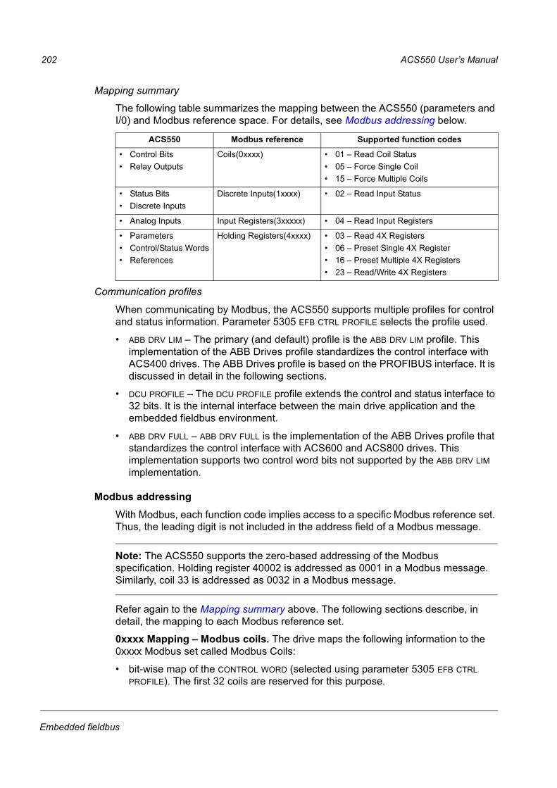
Mapping summary
The following table summarizes the mapping between the ACS550 (parameters and
I/0) and Modbus reference space. For details, see Modbus addressing below.
Communication profiles
When communicating by Modbus, the ACS550 supports multiple profiles for control
and status information. Parameter 5305 EFB CTRL PROFILE selects the profile used.
ABB DRV LIM The primary (and default) profile is the ABB DRV LIM profile. This
implementation of the ABB Drives profile standardizes the control interface with
ACS400 drives. The ABB Drives profile is based on the PROFIBUS interface. It is
discussed in detail in the following sections.
DCU PROFILE The DCU PROFILE profile extends the control and status interface to
32 bits. It is the internal interface between the main drive application and the
embedded fieldbus environment.
ABB DRV FULL ABB DRV FULL is the implementation of the ABB Drives profile that
standardizes the control interface with ACS600 and ACS800 drives. This
implementation supports two control word bits not supported by the ABB DRV LIM
implementation.
Modbus addressing
With Modbus, each function code implies access to a specific Modbus reference set.
Thus, the leading digit is not included in the address field of a Modbus message.
Note: The ACS550 supports the zero-based addressing of the Modbus
specification. Holding register 40002 is addressed as 0001 in a Modbus message.
Similarly, coil 33 is addressed as 0032 in a Modbus message.
Refer again to the Mapping summary above. The following sections describe, in
detail, the mapping to each Modbus reference set.
0xxxx Mapping Modbus coils. The drive maps the following information to the
0xxxx Modbus set called Modbus Coils:
bit-wise map of the CONTROL WORD (selected using parameter 5305 EFB CTRL
PROFILE). The first 32 coils are reserved for this purpose.
ACS550 Modbus reference Supported function codes
Control Bits
Relay Outputs
Coils(0xxxx) 01 Read Coil Status
05 Force Single Coil
15 Force Multiple Coils
Status Bits
Discrete Inputs
Discrete Inputs(1xxxx) 02 Read Input Status
Analog Inputs Input Registers(3xxxxx) 04 Read Input Registers
Parameters
Control/Status Words
References
Holding Registers(4xxxx) 03 Read 4X Registers
06 Preset Single 4X Register
16 Preset Multiple 4X Registers
23 Read/Write 4X Registers

ACS550 Users Manual 203
Embedded fieldbus
relay output states, numbered sequentially beginning with coil 00033.
The following table summarizes the 0xxxx reference set:
For the 0xxxx registers:
Status is always readable.
Forcing is allowed by user configuration of the drive for fieldbus control.
Additional relay outputs are added sequentially.
Modbus ref.
Internal location(all profiles)
ABB DRV LIM (5305 = 0)
DCU PROFILE (5305 = 1)
ABB DRV FULL (5305 = 2)
00001 CONTROL WORD Bit 0 OFF11 STOP OFF11
00002 CONTROL WORD Bit 1 OFF21 START OFF21
00003 CONTROL WORD Bit 2 OFF31 REVERSE OFF31
00004 CONTROL WORD Bit 3 START LOCAL START
00005 CONTROL WORD Bit 4 N/A RESET RAMP_OUT_ZERO1
00006 CONTROL WORD Bit 5 RAMP_HOLD1 EXT2 RAMP_HOLD1
00007 CONTROL WORD Bit 6 RAMP_IN_ZERO1 RUN_DISABLE RAMP_IN_ZERO1
00008 CONTROL WORD Bit 7 RESET STPMODE_R RESET
00009 CONTROL WORD Bit 8 N/A STPMODE_EM N/A
00010 CONTROL WORD Bit 9 N/A STPMODE_C N/A
00011 CONTROL WORD Bit 10 N/A RAMP_2 REMOTE_CMD1
00012 CONTROL WORD Bit 11 EXT2 RAMP_OUT_0 EXT2
00013 CONTROL WORD Bit 12 N/A RAMP_HOLD N/A
00014 CONTROL WORD Bit 13 N/A RAMP_IN_0 N/A
00015 CONTROL WORD Bit 14 N/A REQ_LOCALLOCK N/A
00016 CONTROL WORD Bit 15 N/A TORQLIM2 N/A
00017 CONTROL WORD Bit 16 Does not apply FBLOCAL_CTL Does not apply
00018 CONTROL WORD Bit 17 FBLOCAL_REF
00019 CONTROL WORD Bit 18 START_DISABLE1
00020 CONTROL WORD Bit 19 START_DISABLE2
0002100032
Reserved Reserved Reserved Reserved
00033 RELAY OUTPUT 1 Relay Output 1 Relay Output 1 Relay Output 1
00034 RELAY OUTPUT 2 Relay Output 2 Relay Output 2 Relay Output 2
00035 RELAY OUTPUT 3 Relay Output 3 Relay Output 3 Relay Output 3
00036 RELAY OUTPUT 4 Relay Output 4 Relay Output 4 Relay Output 4
00037 RELAY OUTPUT 5 Relay Output 5 Relay Output 5 Relay Output 5
00038 RELAY OUTPUT 6 Relay Output 6 Relay Output 6 Relay Output 6
1 = Active low

204 ACS550 Users Manual
Embedded fieldbus
The ACS550 supports the following Modbus function codes for coils:
1xxxx Mapping Modbus discrete inputs. The drive maps the following
information to the 1xxxx Modbus set called Modbus Discrete Inputs:
bit-wise map of the STATUS WORD (selected using parameter 5305 EFB CTRL
PROFILE). The first 32 inputs are reserved for this purpose.
discrete hardware inputs, numbered sequentially beginning with input 33.
The following table summarizes the 1xxxx reference set:
Function code Description
01 Read coil status
05 Force single coil
15 (0x0F Hex) Force multiple coils
Modbus ref.
Internal location(all profiles)
ABB DRV
(5305 = 0 OR 2)DCU PROFILE
(5305 = 1)
10001 STATUS WORD Bit 0 RDY_ON READY
10002 STATUS WORD Bit 1 RDY_RUN ENABLED
10003 STATUS WORD Bit 2 RDY_REF STARTED
10004 STATUS WORD Bit 3 TRIPPED RUNNING
10005 STATUS WORD Bit 4 OFF_2_STA1 ZERO_SPEED
10006 STATUS WORD Bit 5 OFF_3_STA1 ACCELERATE
10007 STATUS WORD Bit 6 SWC_ON_INHIB DECELERATE
10008 STATUS WORD Bit 7 ALARM AT_SETPOINT
10009 STATUS WORD Bit 8 AT_SETPOINT LIMIT
10010 STATUS WORD Bit 9 REMOTE SUPERVISION
10011 STATUS WORD Bit 10 ABOVE_LIMIT REV_REF
10012 STATUS WORD Bit 11 EXT2 REV_ACT
10013 STATUS WORD Bit 12 RUN_ENABLE PANEL_LOCAL
10014 STATUS WORD Bit 13 N/A FIELDBUS_LOCAL
10015 STATUS WORD Bit 14 N/A EXT2_ACT
10016 STATUS WORD Bit 15 N/A FAULT
10017 STATUS WORD Bit 16 Reserved ALARM
10018 STATUS WORD Bit 17 Reserved REQ_MAINT
10019 STATUS WORD Bit 18 Reserved DIRLOCK
10020 STATUS WORD Bit 19 Reserved LOCALLOCK
10021 STATUS WORD Bit 20 Reserved CTL_MODE
10022 STATUS WORD Bit 21 Reserved Reserved
10023 STATUS WORD Bit 22 Reserved Reserved
10024 STATUS WORD Bit 23 Reserved Reserved
10025 STATUS WORD Bit 24 Reserved Reserved
10026 STATUS WORD Bit 25 Reserved Reserved
10027 STATUS WORD Bit 26 Reserved REQ_CTL

ACS550 Users Manual 205
Embedded fieldbus
For the 1xxxx registers:
Additional discrete inputs are added sequentially.
The ACS550 supports the following Modbus function codes for discrete inputs:
3xxxx Mapping Modbus inputs. The drive maps the following information to the
3xxxx Modbus addresses called Modbus input registers:
any user defined analog inputs.
The following table summarizes the input registers:
The ACS550 supports the following Modbus function codes for 3xxxx registers:
4xxxx Register mapping. The drive maps its parameters and other data to the
4xxxx holding registers as follows:
4000140099 map to drive control and actual values. These registers are
described in the table below.
4010149999 map to drive parameters 01019999. Register addresses that do
not correspond to drive parameters are invalid. If there is an attempt to read or
write outside the parameter addresses, the Modbus interface returns an
exception code to the controller.
10028 STATUS WORD Bit 27 Reserved REQ_REF1
10029 STATUS WORD Bit 28 Reserved REQ_REF2
10030 STATUS WORD Bit 29 Reserved REQ_REF2EXT
10031 STATUS WORD Bit 30 Reserved ACK_STARTINH
10032 STATUS WORD Bit 31 Reserved ACK_OFF_ILCK
10033 DI1 DI1 DI1
10034 DI2 DI2 DI2
10035 DI3 DI3 DI3
10036 DI4 DI4 DI4
10037 DI5 DI5 DI5
10038 DI6 DI6 DI6
1 = Active low
Function code Description
02 Read input status
Modbus reference
ACS550all profiles
Remarks
30001 AI1 This register shall report the level of Analog Input 1 (0100%).
30002 AI2 This register shall report the level of Analog Input 2 (0100%).
Function code Description
04 Read 3xxxx input status
Modbus ref.
Internal location(all profiles)
ABB DRV
(5305 = 0 OR 2)DCU PROFILE
(5305 = 1)

206 ACS550 Users Manual
Embedded fieldbus
The following table summarizes the 4xxxx drive control registers 4000140099 (for
4xxxx registers above 40099, see the drive parameter list, e.g. 40102 is parameter
0102):
Modbus register Access Remarks
40001 CONTROL WORD R/W Maps directly to the profileS CONTROL WORD. Supported only if 5305 = 0 or 2 (ABB Drives profile). Parameter 5319 holds a copy in hex format.
40002 Reference 1 R/W Range = 0+20000 (scaled to 01105 REF1 MAX), or -200000 (scaled to 1105 REF1 MAX0).
40003 Reference 2 R/W Range = 0+10000 (scaled to 01108 REF2 MAX), or -100000 (scaled to 1108 REF2 MAX0).
40004 STATUS WORD R Maps directly to the profileS STATUS WORD. Supported only if 5305 = 0 or 2 (ABB Drives profile). Parameter 5320 holds a copy in hex format.
40005 Actual 1 (select using 5310)
R By default, stores a copy of 0103 OUTPUT FREQ. Use parameter 5310 to select a different actual value for this register.
40006 Actual 2(select using 5311)
R By default, stores a copy of 0104 CURRENT. Use parameter 5311 to select a different actual value for this register.
40007 Actual 3 (select using 5312)
R By default, stores nothing. Use parameter 5312 to select an actual value for this register.
40008 Actual 4(select using 5313)
R By default, stores nothing. Use parameter 5313 to select an actual value for this register.
40009 Actual 5 (select using 5314)
R By default, stores nothing. Use parameter 5314 to select an actual value for this register.
40010 Actual 6 (select using 5315)
R By default, stores nothing. Use parameter 5315 to select an actual value for this register.
40011 Actual 7 (select using 5316)
R By default, stores nothing. Use parameter 5316 to select an actual value for this register.
40012 Actual 8 (select using 5317)
R By default, stores nothing. Use parameter 5317 to select an actual value for this register.
40031 ACS550 CONTROL WORD LSW
R/W Maps directly to the Least Significant Word of the DCU profiles CONTROL WORD. Supported only if 5305 = 1. See parameter 0301.
40032 ACS550 CONTROL WORD MSW
R Maps directly to the Most Significant Word of the DCU profiles CONTROL WORD. Supported only if 5305 = 1. See parameter 0302.
40033 ACS550 STATUS WORD LSW
R Maps directly to the Least Significant Word of the DCU profiles STATUS WORD. Supported only if 5305 = 1. See parameter 0303.
40034 ACS550 STATUS WORD MSW
R Maps directly to the Most Significant Word of the DCU profiles STATUS WORD. Supported only if 5305 = 1. See parameter 0304.

ACS550 Users Manual 207
Embedded fieldbus
For the Modbus protocol, drive parameters in Group 53: EFB PROTOCOL report the
parameter mapping to 4xxxx Registers.
Except where restricted by the drive, all parameters are available for both reading
and writing. The parameter writes are verified for the correct value and for a valid
register addresses.
Note: Parameter writes through standard Modbus are always volatile i.e. modified
values are not automatically stored to permanent memory. Use parameter 1607
PARAM SAVE to save all altered values.
The ACS550 supports the following Modbus function codes for 4xxxx registers:
Code Description
5310 EFB PAR 10
Specifies the parameter mapped to Modbus register 40005.
5311 EFB PAR 11
Specifies the parameter mapped to Modbus register 40006.
5312 EFB PAR 12
Specifies the parameter mapped to Modbus register 40007.
5313 EFB PAR 13
Specifies the parameter mapped to Modbus register 40008.
5314 EFB PAR 14
Specifies the parameter mapped to Modbus register 40009.
5315 EFB PAR 15
Specifies the parameter mapped to Modbus register 40010.
5316 EFB PAR 16
Specifies the parameter mapped to Modbus register 40011.
5317 EFB PAR 17
Specifies the parameter mapped to Modbus register 40012.
5318 EFB PAR 18
Sets additional delay in milliseconds before the ACS550 begins transmitting response to the master request.
5319 EFB PAR 19
Holds a copy (in hex) of the CONTROL WORD, Modbus register 40001.
5320 EFB PAR 20
Holds a copy (in hex) of the STATUS WORD, Modbus register 40004.
Function code Description
03 Read holding 4xxxx registers
06 Preset single 4xxxx register
16 (0x10 Hex) Preset multiple 4xxxx registers
23 (0x17 Hex) Read/write 4xxxx registers

208 ACS550 Users Manual
Embedded fieldbus
Actual values
The contents of the register addresses 4000540012 are ACTUAL VALUES and are:
specified using parameters 53105317
Read-only values containing information on the operation of the drive
16-bit words containing a sign bit and a 15-bit integer
when negative values, written as the twos complement of the corresponding
positive value
scaled as described earlier in section Actual value scaling on page 197.
Exception codes
Exception codes are serial communication responses from the drive. The ACS550
supports the standard Modbus exception codes defined below.
Exception code
Name Meaning
01 ILLEGAL FUNCTION Unsupported Command
02 ILLEGAL DATA ADDRESS The data address received in the query is not allowable. It is not a defined parameter/group.
03 ILLEGAL DATA VALUE A value contained in the query data field is not an allowable value for the ACS550, because it is one of the following:
Outside min. or max. limits.
Parameter is read-only.
Message is too long.
Parameter write not allowed when start is active.
Parameter write not allowed when factory macro is selected.

ACS550 Users Manual 209
Embedded fieldbus
ABB control profiles technical data
Overview
ABB Drives profile
The ABB Drives profile provides a standard profile that can be used on multiple
protocols, including Modbus and the protocols available on the FBA module. Two
implementations of the ABB Drives profile are available:
ABB DRV FULL This implementation standardizes the control interface with
ACS600 and ACS800 drives.
ABB DRV LIM This implementation standardizes the control interface with
ACS400 drives. This implementation does not support two control word bits
supported by ABB DRV FULL.
Except as noted, the following ABB Drives Profile descriptions apply to both
implementations.
DCU profile
The DCU profile extends the control and status interface to 32 bits. It is the internal
interface between the main drive application and the embedded fieldbus
environment.
Control Word
The CONTROL WORD is the principal means for controlling the drive from a fieldbus
system. The fieldbus master station sends the CONTROL WORD to the drive. The drive
switches between states according to the bit-coded instructions in the CONTROL
WORD. Using the CONTROL WORD requires that:
The drive is in remote (REM) control.
The serial communication channel is defined as the source for controlling
commands (set using parameters such as 1001 EXT1 COMMANDS, 1002 EXT2
COMMANDS and 1102 EXT1/EXT2 SEL).
The serial communication channel used is configured to use an ABB control
profile. For example, to use the control profile ABB DRV FULL requires both
parameter 9802 COMM PROT SEL = 1 (STD MODBUS) and parameter 5305 EFB CTRL
PROFILE = 2 (ABB DRV FULL).

210 ACS550 Users Manual
Embedded fieldbus
ABB Drives profile
The following table and the state diagram later in this sub-section describe the
CONTROL WORD content for the ABB Drives profile.
ABB Drives profile CONTROL WORD (See parameter 5319)
Bit Name ValueCommanded
stateComments
0 OFF1 CONTROL
1 READY TO OPERATE Enter READY TO OPERATE
0 EMERGENCY OFF Drive ramps to stop according to currently active deceleration ramp (2203 or 2205)
Normal command sequence:
Enter OFF1 ACTIVE
Proceed to READY TO SWITCH ON, unless other interlocks (OFF2, OFF3) are active.
1 OFF2 CONTROL
1 OPERATING Continue operation (OFF2 inactive)
0 EMERGENCY OFF Drive coasts to stop.
Normal command sequence:
Enter OFF2 ACTIVE
Proceed to SWITCHON INHIBITED
2 OFF3 CONTROL
1 OPERATING Continue operation (OFF3 inactive)
0 EMERGENCY STOP Drive stops within time specified by parameter 2208.
Normal command sequence:
Enter OFF3 ACTIVE
Proceed to SWITCH ON INHIBITED
WARNING! Be sure motor and driven equipment can be stopped using this mode.
3 INHIBIT OPERATION
1 OPERATION ENABLED
Enter OPERATION ENABLED (Note the Run enable signal must be active. See 1601. If 1601 is set to COMM, this bit also actives the Run Enable signal.)
0 OPERATION INHIBITED
Inhibit operation. Enter OPERATION INHIBITED
4 Unused (ABB DRV LIM)
RAMP_OUT_ZERO (ABB DRV FULL)
1 NORMAL OPERATION Enter RAMP FUNCTION GENERATOR: ACCELERATION ENABLED
0 RFG OUT ZERO Force ramp function generator output to Zero. Drive ramps to stop (current and DC voltage limits in force).
5 RAMP_HOLD 1 RFG OUT ENABLED Enable ramp function.
Enter RAMP FUNCTION GENERATOR: ACCELERATOR ENABLED
0 RFG OUT HOLD Halt ramping (Ramp Function Generator output held)
6 RAMP_IN_ZERO
1 RFG INPUT ENABLED Normal operation. Enter OPERATING
0 RFG INPUT ZERO Force Ramp Function Generator input to zero.

ACS550 Users Manual 211
Embedded fieldbus
DCU Profile
The following tables describe the CONTROL WORD content for the DCU profile.
7 RESET 0=>1 RESET Fault reset if an active fault exists (Enter SWITCH-ON INHIBITED). Effective if 1604 = COMM.
0 OPERATING Continue normal operation
89 Unused
10 Unused (ABB DRV LIM)
REMOTE_CMD (ABB DRV FULL)
1 Fieldbus control enabled.
0 CW 0 or Ref 0: Retain last CW and Ref.
CW = 0 and Ref = 0: Fieldbus control enabled.
Ref and deceleration/acceleration ramp are locked.
11 EXT CTRL LOC 1 EXT2 SELECT Select external control location 2 (EXT2). Effective if 1102 = COMM.
0 EXT1 SELECT Select external control location 1 (EXT1). Effective if 1102 = COMM.
1215
Unused
DCU profile CONTROL WORD (See parameter 0301)
Bit Name Value Command/Req. Comments
0 STOP 1 Stop Stops according to either the stop mode parameter or the stop mode requests (bits 7 and 8).
Simultaneous STOP and START commands result in a stop command.
0 (no op)
1 START 1 Start
0 (no op)
2 REVERSE 1 Reverse direction This bit XORd with the sign of the reference defines direction.
0 Forward direction
3 LOCAL 1 Local mode When the fieldbus sets this bit, it steals control and the drive moves to fieldbus local control mode.0 External mode
4 RESET -> 1 Reset Edge sensitive.
other (no op)
5 EXT2 1 Switch to EXT2
0 Switch to EXT1
6 RUN_DISABLE 1 Run disable Inverted run enable.
0 Run enable on
7 STPMODE_R 1 Normal ramp stop mode
0 (no op)
ABB Drives profile CONTROL WORD (See parameter 5319)
Bit Name ValueCommanded
stateComments
=/ =/

212 ACS550 Users Manual
Embedded fieldbus
Status Word
The contents of the STATUS WORD is status information, sent by the drive to the
master station.
8 STPMODE_EM 1 Emergency ramp stop mode
0 (no op)
9 STPMODE_C 1 Coast stop mode
0 (no op)
10 RAMP_2 1 Ramp pair 2
0 Ramp pair 1
11 RAMP_OUT_0 1 Ramp output to 0
0 (no op)
12 RAMP_HOLD 1 Ramp freeze
0 (no op)
13 RAMP_IN_0 1 Ramp input to 0
0 (no op)
14 RREQ_LOCALLOC
1 Local mode lock In lock, drive will not switch to local mode.
0 (no op)
15 TORQLIM2 1 Torque limit pair 2
0 Torque limit pair 1
DCU profile CONTROL WORD (See parameter 0302)
Bit Name Value Function Comments
1626 Reserved
27 REF_CONST 1 Constant speed ref. These bits are only for supervision purposes.
0 (no op)
28 REF_AVE 1 Average speed ref.
0 (no op)
29 LINK_ON 1 Master is detected in link
0 Link is down
30 REQ_STARTINH 1 Start inhibit request is pending
0 Start inhibit request is OFF
31 OFF_INTERLOCK 1 Panel OFF button pressed
For the control panel (or PC tool) this is the OFF button interlock.
0 (no op)
DCU profile CONTROL WORD (See parameter 0301)
Bit Name Value Command/Req. Comments

ACS550 Users Manual 213
Embedded fieldbus
ABB Drives profile
The following table and the state diagram later in this sub-section describe the
STATUS WORD content for the ABB Drives profile.
ABB Drives profile (EFB) STATUS WORD (See parameter 5320)
Bit Name ValueDescription
(Correspond to states/boxes in the state diagram)
0 RDY_ON 1 READY TO SWITCH ON
0 NOT READY TO SWITCH ON
1 RDY_RUN 1 READY TO OPERATE
0 OFF1 ACTIVE
2 RDY_REF 1 OPERATION ENABLED
0 OPERATION INHIBITED
3 TRIPPED 01 FAULT
0 No fault
4 OFF_2_STA 1 OFF2 INACTIVE
0 OFF2 ACTIVE
5 OFF_3_STA 1 OFF3 INACTIVE
0 OFF3 ACTIVE
6 SWC_ON_INHIB 1 SWITCH-ON INHIBIT ACTIVE
0 SWITCH-ON INHIBIT NOT ACTIVE
7 ALARM 1 Alarm (See section Alarm listing on page 250 for details on alarms.)
0 No alarm
8 AT_SETPOINT 1 OPERATING. Actual value equals (within tolerance limits) the reference value.
0 Actual value is outside tolerance limits (not equal to reference value).
9 REMOTE 1 Drive control location: REMOTE (EXT1 or EXT2)
0 Drive control location: LOCAL
10 ABOVE_LIMIT 1 Supervised parameters value > supervision high limit.
Bit remains 1 until supervised parameters value < supervision low limit.
See Group 32: SUPERVISION.
0 Supervised parameters value < supervision low limit.
Bit remains 0 until supervised parameters value > supervision high limit.
See Group 32: SUPERVISION.
11 EXT CTRL LOC 1 External control location 2 (EXT2) selected
0 External control location 1 (EXT1) selected
12 EXT RUN ENABLE 1 External Run Enable signal received
0 No External Run Enable signal received
13 15
Unused

214 ACS550 Users Manual
Embedded fieldbus
DCU profile
The following tables describe the STATUS WORD content for the DCU profile.
DCU profile STATUS WORD (See parameter 0303)
Bit Name Value Status
0 READY 1 Drive is ready to receive start command.
0 Drive is not ready.
1 ENABLED 1 External run enable signal received.
0 No external run enable signal received.
2 STARTED 1 Drive has received start command.
0 Drive has not received start command.
3 RUNNING 1 Drive is modulating.
0 Drive is not modulating.
4 ZERO_SPEED 1 Drive is at zero speed.
0 Drive has not reached zero speed.
5 ACCELERATE 1 Drive is accelerating.
0 Drive is not accelerating.
6 DECELERATE 1 Drive is decelerating.
0 Drive is not decelerating.
7 AT_SETPOINT 1 Drive is at setpoint.
0 Drive has not reached setpoint.
8 LIMIT 1 Operation is limited by Group 20: LIMITS settings.
0 Operation is within Group 20: LIMITS settings.
9 SUPERVISION 1 A supervised parameter (Group 32: SUPERVISION) is outside its limits.
0 All supervised parameters are within limits.
10 REV_REF 1 Drive reference is in reverse direction.
0 Drive reference is in forward direction.
11 REV_ACT 1 Drive is running in reverse direction.
0 Drive is running in forward direction.
12 PANEL_LOCAL 1 Control is in control panel (or PC tool) local mode.
0 Control is not in control panel local mode.
13 FIELDBUS_LOCAL 1 Control is in fieldbus local mode (steals control panel local).
0 Control is not in fieldbus local mode.
14 EXT2_ACT 1 Control is in EXT2 mode.
0 Control is in EXT1 mode.
15 FAULT 1 Drive is in a fault state.
0 Drive is not in a fault state.

ACS550 Users Manual 215
Embedded fieldbus
DCU profile STATUS WORD (See parameter 0304)
Bit Name Value Status
16 ALARM 1 An alarm is on.
0 No alarms are on.
17 REQ_MAINT 1 A maintenance request is pending.
0 No maintenance request is pending.
18 DIRLOCK 1 Direction lock is ON. (Direction change is locked out.)
0 Direction lock is OFF.
19 LOCALLOCK 1 Local mode lock is ON. (Local mode is locked out.)
0 Local mode lock is OFF.
20 CTL_MODE 1 Drive is in vector control mode.
0 Drive is in scalar control mode.
2125 Reserved
26 REQ_CTL 1 Copy the control word
0 (no op)
27 REQ_REF1 1 Reference 1 requested in this channel.
0 Reference 1 is not requested in this channel.
28 REQ_REF2 1 Reference 2 requested in this channel.
0 Reference 2 is not requested in this channel.
29 REQ_REF2EXT 1 External PID reference 2 requested in this channel.
0 External PID reference 2 is not requested in this channel.
30 ACK_STARTINH 1 A start inhibit from this channel is granted.
0 A start inhibit from this channel is not granted.
31 ACK_OFF_ILCK 1 Start inhibit due to OFF button
0 Normal operation
216 ACS550 Users Manual
Embedded fieldbus
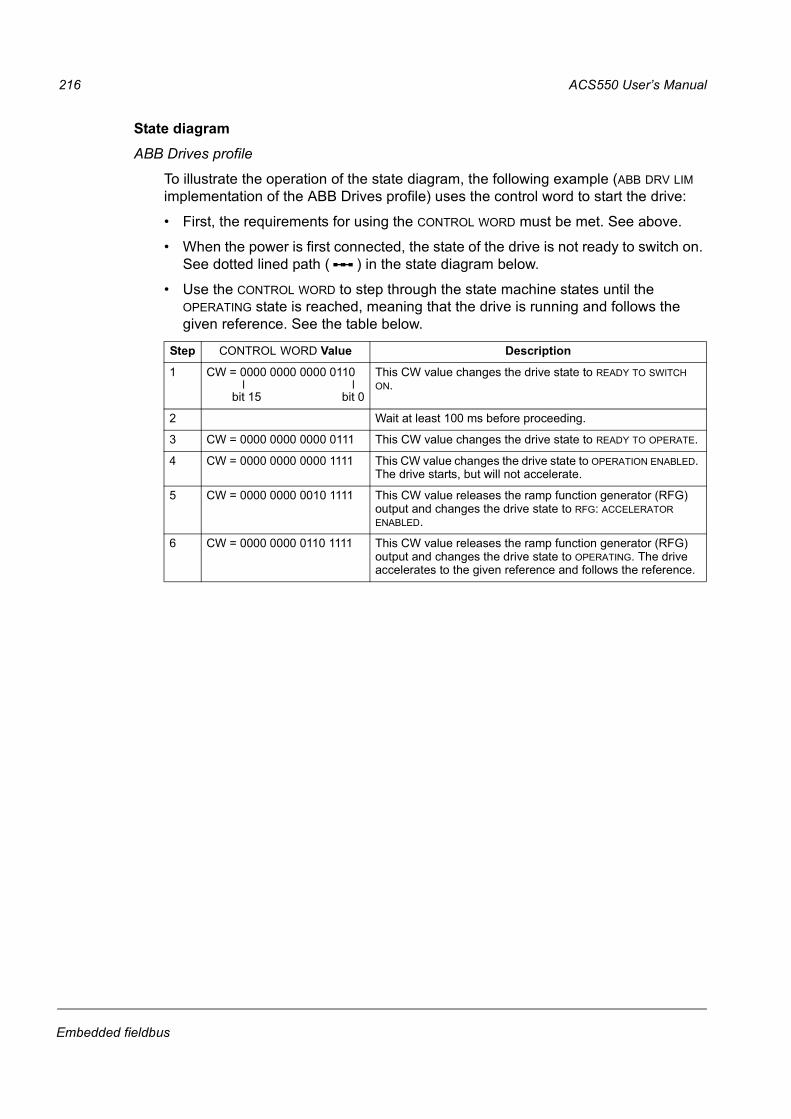
State diagram
ABB Drives profile
To illustrate the operation of the state diagram, the following example (ABB DRV LIM
implementation of the ABB Drives profile) uses the control word to start the drive:
First, the requirements for using the CONTROL WORD must be met. See above.
When the power is first connected, the state of the drive is not ready to switch on.
See dotted lined path ( ) in the state diagram below.
Use the CONTROL WORD to step through the state machine states until the
OPERATING state is reached, meaning that the drive is running and follows the
given reference. See the table below.
Step CONTROL WORD Value Description
1 CW = 0000 0000 0000 0110 This CW value changes the drive state to READY TO SWITCH ON.
2 Wait at least 100 ms before proceeding.
3 CW = 0000 0000 0000 0111 This CW value changes the drive state to READY TO OPERATE.
4 CW = 0000 0000 0000 1111 This CW value changes the drive state to OPERATION ENABLED. The drive starts, but will not accelerate.
5 CW = 0000 0000 0010 1111 This CW value releases the ramp function generator (RFG) output and changes the drive state to RFG: ACCELERATOR ENABLED.
6 CW = 0000 0000 0110 1111 This CW value releases the ramp function generator (RFG) output and changes the drive state to OPERATING. The drive accelerates to the given reference and follows the reference.
bit 0bit 15

ACS550 Users Manual 217
Embedded fieldbus
The state diagram below describes the start-stop function of CONTROL WORD (CW)
and STATUS WORD (SW) bits for the ABB Drives profile.
(CW xxxx x1xx xxxx x110)
MAINS OFF
Power ON (CW Bit0=0)
(SW Bit6=1)
(SW Bit0=0)
From any state
n(f)=0 / I=0
OFF1 (CW Bit0=0)
A C D
(CW Bit3=0)
(SW Bit2=0) (SW Bit0=1)
(CW= xxxx x1xx xxxx x111)
(SW Bit1=1)
(CW Bit3=1 and(CW Bit4=0)*
n(f)=0 / I=0
From any state
SWITCH-ONINHIBITED
NOT READYTO SWITCH ON
OPERATIONINHIBITED
READY TOSWITCH ON
READY TOOPERATE
RFG OUTPUTENABLED*
C* D*
From any state
Emergency OffOFF2 (CW Bit1=0)
(SW Bit4=0)OFF2
ACTIVE
From any state
Fault
(SW Bit3=1)FAULT
(CW Bit7=1)**
(SW Bit5=0)
Emergency StopOFF3 (CW Bit2=0)
SW Bit12=1)
RFG: ACCELERATORENABLED
(CW=xxxx x1xx xx11* 1111(CW Bit6=0)
C(CW=xxxx x1xx x111* 1111
(SW Bit8=1)
D
B*
D
OPERATING
OFF3ACTIVE
KEY
State
State change
Path described in example
CW = CONTROL WORD
SW = STATUS WORD
RFG = Ramp Function Generator
I = Param. 0104 CURRENT
f = Param. 0103 OUTPUT FREQ
n = Speed
* Indicates the features not in ABB DRV LIM
** This state transition also occurs if the fault is reset from any other source (e.g. digital input).
(SW Bit2=1)OPERATION
ENABLED
(CW=xxxx x1xx xxx1* 1111
A(CW Bit5=0)
C D
B*
B*
(SW Bit1=0)OFF1
ACTIVE
OPERATION INHIBITED
i.e. Bit 4=1)*
i.e. Bit 5=1)
i.e. Bit 6=1)

218 ACS550 Users Manual
Embedded fieldbus
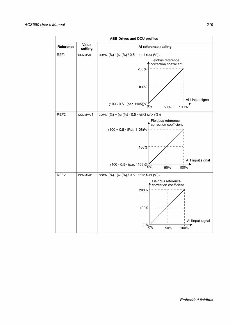
Reference scaling
ABB Drives and DCU profiles
The following table describes REFERENCE scaling for the ABB Drives and DCU
profiles.
Note: The setting of parameter 1104 REF1 MIN and 1107 REF2 MIN has no effect on
the scaling of references.
When parameter 1103 REF1 SELECT or 1106 REF2 SELECT is set to COMM+AI1 or
COMM*AI1, the reference is scaled as follows:
ABB Drives and DCU profiles
Reference RangeReference
typeScaling Remarks
REF1 -32767+32767
Speed or frequency
-20000 = -(par. 1105)0 = 0+20000 = (par. 1105)
(20000 corresponds to 100%)
Final reference limited by 1104/1105. Actual motor speed limited by 2001/2002 (speed) or 2007/2008 (frequency).
REF2 -32767+32767
Speed or frequency
-10000 = -(par. 1108)0 = 0+10000 = (par. 1108)
(10000 corresponds to 100%)
Final reference limited by 1107/1108. Actual motor speed limited by 2001/2002 (speed) or 2007/2008 (frequency).
Torque -10000 = -(par. 1108)0 = 0+10000 = (par. 1108)
(10000 corresponds to 100%)
Final reference limited by 2015/2017 (torque1) or 2016/2018 (torque2).
PID Reference
-10000 = -(par. 1108)0 = 0+10000 = (par. 1108)
(10000 corresponds to 100%)
Final reference limited by 4012/4013 (PID set1) or 4112/4113 (PID set2).
ABB Drives and DCU profiles
ReferenceValue
settingAI reference scaling
REF1 COMM+AI1 COMM (%) +(AI (%) - 0.5 · REF1 MAX (%))
0% 50%
(100 + 0.5 · (Par. 1105)%
(100 - 0.5 · (par. 1105))%
100%
100%
AI1 input signal
Fieldbus referencecorrection coefficient
ACS550 Users Manual 219
Embedded fieldbus
REF1 COMM*AI1 COMM (%) · (AI (%) / 0.5 · REF1 MAX (%))
REF2 COMM+AI1 COMM (%) + (AI (%) - 0.5 · REF2 MAX (%))
REF2 COMM*AI1 COMM (%) · (AI (%) / 0.5 · REF2 MAX (%))
ABB Drives and DCU profiles
ReferenceValue
settingAI reference scaling
0% 50%
200%
(100 - 0.5 · (par. 1105))%
100%
100%
AI1 input signal
Fieldbus referencecorrection coefficient
0% 50%
(100 + 0.5 · (Par. 1108)%
(100 - 0.5 · (par. 1108)%
100%
100%
AI1 input signal
Fieldbus referencecorrection coefficient
0% 50%
200%
0%
100%
100%
AI1input signal
Fieldbus referencecorrection coefficient

220 ACS550 Users Manual
Embedded fieldbus
Reference handling
Use Group 10: START/STOP/DIR parameters to configure for control of rotation
direction for each control location (EXT1 and EXT2). The following diagrams illustrate
how group 10 parameters and the sign of the fieldbus reference interact to produce
REFERENCE values (REF1 and REF2). Note, fieldbus references are bipolar, that is
they can be positive or negative.
ABB Drives profile
Parameter Value setting AI reference scaling
1003 DIRECTION 1 (FORWARD)
1003 DIRECTION 2 (REVERSE)
1003 DIRECTION 3 (REQUEST)
100%
Max. ref
-100%-163% 163%
-(Max. ref.)
Fieldbus
Resultant ref.
reference
100%
Max. ref
-100%-163% 163%
-(Max. ref.)
Fieldbus
Resultant ref.
reference
100%
Max. ref
-100%-163%
163%
-(Max. ref.)
Fieldbus
Resultant ref.
reference


![ABB ACS550-02 & ACS550-U2 Drives User's ManualNote: ACS550-U2 Installation Supplement [3AUA0000004067 (English)] provides more information about the installation of ACS550-U2 drives](https://img.pdfslide.us/doc/110x75/5ed1e5e176055c3966516719/abb-acs550-02-acs550-u2-drives-users-manual-note-acs550-u2-installation.jpg)