Embed Size (px)
Citation preview

air cadet publicationACP 32
navigation
volume 3 - air navigation
COMBI
NED
CADET FORCE
Uncontrolled copy not subject to amendment
Revision 1.00

Amendment List DateAmended by Incorporated
No Date
1
2
3
4
5
6
7
8
9
10
11
12
13
14
15
16
i
© Crown Copyright 2007
Uncontrolled copy not subject to amendment
Revision 1.00

CONTENTS
ACP 32NAVIGATION
ii
ISSUED 2000
Chapter 1 ................. Distance speed and time
Chapter 2 ................. The Triangle of Velocities
Chapter 3 ................. The 1 in 60 rule
Chapter 4 ................. Compasses
Chapter 5 ................. Weather
Instructors’ Guide
Volume 1 .................. Map reading
Volume 2 .................. Basic Navigation
Volume 3................. Air Navigation
Volume 4 .................. Pilot Navigation
Volume 3
Air Navigation
Uncontrolled copy not subject to amendment
Revision 1.00

iii
Uncontrolled copy not subject to amendment
Revision 1.00

DISTANCE/SPEED/TIME
CHAPTER 1
The nautical mile
DISTANCE/SPEED/TIME
Introduction
1. Aircrew will always need to know how long it will take for an aircraft to fly fromA to B, maybe just to deliver passengers or payload on time but also becauseaircraft, unlike cars, cannot afford to run out of fuel. Regular checks have to be madethat the time of arrival will occur before the fuel has all been used. To do this, it isnecessary to know how far the aircraft has left to fly and how fast it is going over theground.
Distance On The Earth
2. Although the Earth is not perfectly round, we users of maps can safely assumethat the Earth is a sphere. In ACP 32 Volume 1 we learned that the Latitude/Longitudegrid divides the surface of the Earth into degrees and minutes. One minute of latituderepresents one nautical mile (nm) and 1 degree of latitude (60 minutes) equals60nm. As a complete circle is 360°, the 360 x 60 gives the circumference of theEarth as 21600 nm (approx 25000 statute miles). Notice that on nautical maps orcharts there are no scales on the borders, so we have to use the nm scale which isshown along each meridian. Note also that the scale along the parallels is not usedbecause convergence shrinks the scale considerably in the British latitudes, andeven more near the Poles.
Scales on parallels arenot used
Fig 1-1 RAF enroute
chart
32.3.1-1
Uncontrolled copy not subject to amendment
Revision 1.00

3. In the example at fig 1-1, measure the distance between Shawbury andBirmingham, using the nm scale printed on the 002º West Meridian. This can bedone with a ruler, a pair of dividers, or if you do not have any equipment, using themarks along the edge of any piece of paper.
Change of Latitude
4. If two places are on the same meridian then it is possible to calculate thedistance between them rather than having to measure it; this is much simpler if severalmap sheets are involved. For example Torrejon airfield (near Madrid in Spain) isdue south of RAF St Athan. These two latitudes are N40º29’ and N51º24’. Subtractingone latitude from the other gives a change of latitude of 10º55’. Multiply 10º by 60and add 55’ to find that Torrejon and St Athan are 655nm apart. However, very few airjourneys are made along meridians so to find out how far apart other airfields are, weeither have to measure the distance on a suitable small-scale chart or allow ournavigational computer to do the calculation for us using spherical trigonometry.
Aircraft Speed
5. We measure the speed of land-based vehicles (eg cars, bicycles) in milesper hour (mph). In aviation, as we use nm to measure distances, it follows thatspeed is measured in nm per hour (known as knots from the days of sailing ships).The other difference from land-based vehicles is that aircraft are not on the ground,the speed of rotation of the wheels cannot be used to drive a speedometer. As theaircraft flies through the air, we use an instrument called an Air Speed Indicator (ASI)to measure the “Dynamic Pressure” which is the pressure caused by the forwardmotion of the aircraft. We achieve this by measuring the difference between thepressure of the air surrounding the aircraft (atmospheric or “Static Pressure”) and thepressure of the air captured in the Pitot Tube (“Pitot Pressure”), which is made up ofstatic and dynamic pressure.
CHAPTER 1
32.3.1-2
Fig 1-2 A Simplified AirSpeed Indicator
Units of speed
Find the distancebetween 2 places
Distance betweenplaces on the samemeridian
Air speed indicator
Uncontrolled copy not subject to amendment
Revision 1.00
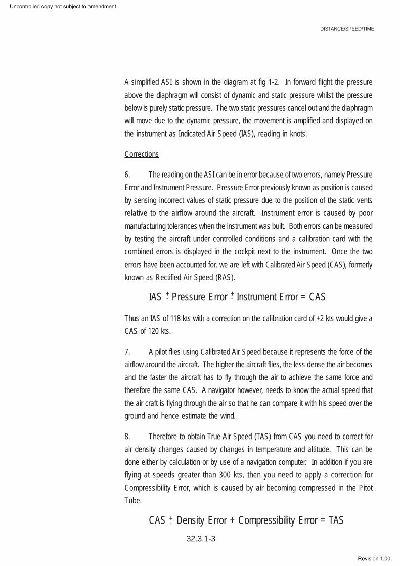
A simplified ASI is shown in the diagram at fig 1-2. In forward flight the pressureabove the diaphragm will consist of dynamic and static pressure whilst the pressurebelow is purely static pressure. The two static pressures cancel out and the diaphragmwill move due to the dynamic pressure, the movement is amplified and displayed onthe instrument as Indicated Air Speed (IAS), reading in knots.
Corrections
6. The reading on the ASI can be in error because of two errors, namely PressureError and Instrument Pressure. Pressure Error previously known as position is causedby sensing incorrect values of static pressure due to the position of the static ventsrelative to the airflow around the aircraft. Instrument error is caused by poormanufacturing tolerances when the instrument was built. Both errors can be measuredby testing the aircraft under controlled conditions and a calibration card with thecombined errors is displayed in the cockpit next to the instrument. Once the twoerrors have been accounted for, we are left with Calibrated Air Speed (CAS), formerlyknown as Rectified Air Speed (RAS).
IAS Pressure Error Instrument Error = CAS
Thus an IAS of 118 kts with a correction on the calibration card of +2 kts would give aCAS of 120 kts.
7. A pilot flies using Calibrated Air Speed because it represents the force of theairflow around the aircraft. The higher the aircraft flies, the less dense the air becomesand the faster the aircraft has to fly through the air to achieve the same force andtherefore the same CAS. A navigator however, needs to know the actual speed thatthe air craft is flying through the air so that he can compare it with his speed over theground and hence estimate the wind.
8. Therefore to obtain True Air Speed (TAS) from CAS you need to correct forair density changes caused by changes in temperature and altitude. This can bedone either by calculation or by use of a navigation computer. In addition if you areflying at speeds greater than 300 kts, then you need to apply a correction forCompressibility Error, which is caused by air becoming compressed in the PitotTube.
CAS Density Error + Compressibility Error = TAS
DISTANCE/SPEED/TIME
32.3.1-3
+- +-
+-
Uncontrolled copy not subject to amendment
Revision 1.00

CHAPTER 1
32.3.1-4
Units of Time
9. Time is probably the only example of scientific measurement where everynation uses the same units. Everyone is familiar with days, hours and minutes; it isonly necessary to ensure that you use hours when working with knots, as this speedis actually nautical miles per hour. In military and commercial aviation the 24 hourclock is used, set to Greenwich Mean Time GMT or Coordinated Universal Time(UTC) as it is now known. In other words Summer Time or Daylight Saving Time isalways ignored.
Calculation of Time of Flight (Still Air)
10. If a car travels 120 miles at 60 mph, it will take 2 hours to complete thejourney. This is found by the Distance/Speed/Time (DST) formula:
11. This same formula can be used for an aircraft flying in still air. For example,a Nimrod flying at a TAS of 400 kts over an 1800 nm sector will take 4 ½ hours in stillair.
12. This formula can also be re-arranged to find distance or speed if the othertwo quantities are known.
13. Here is an example of how to calculate speed given distance and time.How fast must we go to cover 1500 nm in 5 hours?
Which time do we use?
The DST formula
2
60120
)()()( ===
SSPEEDDDISTANCE
TTIME
TIMEDISTANCE
SPEED = TIMESPEEDDISTANCE ×=
TIME
DISTANCESPEED =
Uncontrolled copy not subject to amendment
Revision 1.00

Using:
Manipulation of equations
Simple equations can easily be manipulated using cross multiplication. That is,numbers on one side of the equation can cross the equals sign to the other sideprovided that, if the number is below the line (division) when it changes side, itcomes above the line multiplication) and vice-versa. For example:
ktsSPEED 300
51500
==
TIMESPEEDDISTANCE ×=
TIMESPEEDDISTANCE ×= SPEED
TIMEDISTANCE
=
TIMESPEED
DISTANCE=
32.3.1-5
DISTANCE/SPEED/TIME
Uncontrolled copy not subject to amendment
Revision 1.00

32.3.1-6
CHAPTER 1
Self Assessment Questions
1. One degree of latitude represents:
a. 1 nm
b. 6 nm
c. 60 nm
d. 360 nm
2. Glasgow is due north of Plymouth (approximately on the samemeridian). If Glasgow is latitude 55°50’ and Plymouth is latitude 50°25’what distance are the two places apart?
a. 525 nm
b. 275 nm
c. 450 nm
d. 325 nm
3. In the RAF, aircraft speeds are generally expressed in:
a. metres per second
b. miles per hour
c. nautical miles per second
d. knots
4. An ASI has an instrument correction factor of +3 kts and a pressurecorrection factor of -1 kts. If the instrument reads 130 kts what is theCAS?
a. 130 kts
b. 132 kts
c. 133 kts
d. 134 kts
5. A Tornado is flying at a TAS of 400 kts. How far will it travel in 2 hrs?
a. 200 nm
b. 200 km
c. 800 nm
d. 800 km
Uncontrolled copy not subject to amendment
Revision 1.00

THE TRIANGLE OF VELOCITIES
THE TRIANGLE OF VELOCITIES
Introduction
1. So far, we have talked about flying in still air conditions. It is now necessaryto consider the wind, which is simply air that is moving.
Vectors and Velocity
2. Whenever we talk about aircraft or wind movement, we must always giveboth the direction and speed of the movement. Direction and speed together arecalled a velocity. A velocity can be represented on a piece of paper by a line calleda vector. The bearing of the line (usually relative to true north) represents the directionof the movement, and the length of the line represents the speed.
The Vector Triangle
3. Let us begin with a situation in everyday life, which we can easily relate to thevector triangle. Imagine two children, one either side of a river, with a toy boat drivenby an electric motor (Fig 2-2). The boat has a rudder to keep it on a straight courseand has a speed of 2 knots. Child A stands on the southern bank and points the boatat her friend on the other side of the river. If the river is not flowing the boat will crossthe river at right angles and reach child B on the other side.
Vectors can be addedtogether
Representing vectors
Fig 2-1 Representationof vectors
CHAPTER 2
True NorthTrack of 070ºSpeed of 120 kts(070/120)
True North
Track of 115ºSpeed of 240 kts(115/240)
A
B
32.3.2-1
Uncontrolled copy not subject to amendment
Revision 1.00

CHAPTER 2
32.3.2-2
4. However, rivers flow downstream towards the sea, so let us look at a riverwhere the speed of the current is 2 knots. Picture child B putting the boat in the waterpointing at his friend. Where will the boat reach the other bank?
5. The vector triangle solves this problem for us. In Fig 2-3, the velocity of theboat is shown as the line with the single arrow crossing the river, and the watervelocity is the line with the three arrowheads pointing downstream. The two lines arethe same length as they both represent a speed of 2 knots. By joining the two endsto make a triangle, the third side of the vector triangle (called the resultant and indicatedby arrowheads) represents the actual movement of the boat as it crabs across theriver. By use of Pythagoras’s theorem it can be shown that the speed of the boatover the riverbed is 2.83 knots. So, child A has to walk downstream to point C tocollect the boat. If she now wishes to send the boat back to B, without making childB walk along the bank, she must walk upstream twice as far (to a point D – see Fig 2-4) before launching the boat again on a heading at right angles to the stream. Anothersolution is possible if child A can alter the speed of the boat, she can go to point A,set the speed to 2.83 knots and launch the boat pointing at E, because it will thentravel directly from A to B as required.
Vector Triangle
Fig 2-3 When the water in theriver is moving
AD
B
A
E B
Solution 1 Solution 2
Fig 2-4
A C
B
Uncontrolled copy not subject to amendment
Revision 1.00

THE TRIANGLE OF VELOCITIES
The Air Triangle
6. Exactly the same triangle can be used to show the motion of a aircraft throughthe air which is itself moving. There are two differences. The first is that we label thetriangle with new names (eg wind instead of current).
The second is that as the aircraft speed is normally a lot more than the wind speed,the triangle will be much longer and thinner than the squat triangle, which representsthe movement of the toy boat. There are 6 components of the air triangle, and theyare described in the next 3 paragraphs.
Heading and TAS
7. The heading of the aircraft is the direction that the aircraft is pointing (ie whatis on the compass). The TAS is the speed of the aircraft through the air, taking intoaccount all the corrections mentioned in Chapter 1. This vector, shown by a line ofscale length, carries one arrow. Remember, the vector represents 2 components,HDG and TAS.
Wind Velocity
8. This is a scale line with 3 arrows; it represents 2 more components, the windspeed and the direction FROM WHICH IT IS BLOWING (northerly in the diagram).
Track and Groundspeed
9. The remaining 2 components in the air triangle are the direction and speedthat the aircraft is actually moving over the ground. This vector has 2 arrows, and it isthe resultant of the other 2 vectors. Note that the number of arrows put on eachvector is simply a convention that is used, to avoid confusing one with the other.
The air Triangle ofvelocities
Heading and True Air Speed (HDG/TAS)
Wind Speed& Direction
Track and Ground Speed (TK/GS)
Drift
Fig 2-5 Air triangle of velocities
32.3.2-3
Some definitions
Uncontrolled copy not subject to amendment
Revision 1.00

CHAPTER 2
32.3.2-4
Drift
10. Drift is the angle between the heading and track vectors and represents theangle at which the aircraft is being blown sideways. It is labelled Left or Right,depending on which way the aircraft is blown. Of course, if you fly directly into windor directly downwind, heading will be the same as track and there will be no drift.The TAS and GS will in this case differ by exactly the value of the wind speed.
The Real World
11. All this theory is all very well but what happens in the real world? There arethree likely scenarios when we have to solve the triangle of Velocities. The first is atthe planning stage of a flight, once we have decided our route; we know our tracksand distances from start to destination. We also know the performance of the aircraftand given the temperature and height we can calculate the TAS, in addition to thetemperature the Met Office will also provide us with the forecast W/V. Given 4 of the6 elements of Triangle of Velocities (TAS, TK, Wind Speed and Direction) it is nowpossible to solve the other two quantities (GS & HDG) and then use the DST formulato calculate how long the flight will take. The second scenario is in the air when weknow the TAS and HDG, and we can measure out TK and GS by watching our changingposition over the ground. From these 4 items, we can calculate the W/V. The finalscenario occurs when you know your heading and TAS and have a reliable W/V butare over a featureless area such as the sea and are unable to take any form of fix,then by applying the W/V to your heading and TAS you can calculate your track andGroundspeed. Once you have TK and G/S you can produce a deduced reckoningposition (DR position) by applying the time from your last known position to the G/Sto give you a distance along TK.
Computers
12. So far we have only talked about drawing vectors on paper. This is fine inthe office or classroom but impossible in the cramped confines of a small aircraft.For many years, navigators have been using the Dalton hand held computer (Fig 2-6) and these are still used in the private flying world. The fast jet navigator in the RAFsolves the triangle using a simplified mental calculation, which is beyond the scopeof this course. In civil airliners an onboard electronic computer continually solvesthe triangle and many other things besides.
Uncontrolled copy not subject to amendment
Revision 1.00

THE TRIANGLE OF VELOCITIES
Magic Numbers
13. All aviators, no matter how much help they have from electronics, have to doa lot of mental arithmetic. This can be made much easier if magic numbers are used.The numbers in question are the ground speeds in nautical miles per minutes; someexamples are shown in the table below. It does not matter if you are flying in a Tutoror a Tornado, the method works equally well.
Examples
14. You are in a Tornado at low level over Wales, doing 420 knots GS and youhave 49 miles to run to the next turning point, how long will this take? Divide 49 by 7and the answer is 7 minutes to go.
15. You are on a cross-country exercise in a Tutor, heading into wind at 80 knotsGS. How long will a 20 mile leg take? To divide 20 by 11/3, is the same as dividingby 4/3 or multiplying by ¾. However, there is a much easier method in this example.As the distance is ¼ of the speed, it must take one quarter of an hour.
Magic numbers
Fig 2-6 The RAF’sDalton computer
32.3.2-5
GS nm/min GS nm/min
60 1 210 31/2 80 11/3 240 4 90 11/2 300 5
100 12/3 360 6 120 2 420 7 150 21/2 480 8 180 3 540 9
Uncontrolled copy not subject to amendment
Revision 1.00

CHAPTER 2
32.3.2-6
Six Minute Magic
16. With the slower speeds it is often easier to think in terms of how far do we goin 6 minutes (1 tenth of an hour). This is simply the ground speed with the last zeroremoved. So the Tutor above doing 80 knots, will travel 8 miles in 6 minutes. Forshort legs this is a much more useful calculation.
Time Of Arrival
17. A by-product of solving the triangle of velocities is that by making the DSTcalculation using GS and distance To Go, we can calculate the time that it will take toreach the next turning point or destination. This time is called Estimated Time ofArrival (ETA) and is important both for fuel calculations and for Air Traffic controlpurposes. A particular application of this is the ETA for the destination. If you do notarrive on time, Air Traffic will have to take overdue action; very similar to the way asearch party goes out to find a group of walkers who have not returned from a mountaintrek on time.
Conclusion
18. Hopefully this chapter will have convinced you that despite all the computers,some mental arithmetic is essential, whether you plan to join the RAF as aircrew,become an airline pilot, obtain a PPL, or simply make the most of the available airexperience opportunities. The starting point is the 6 times table; no one in their rightmind would dream of aviating without this knowledge.
6 minute magic
ETA
Uncontrolled copy not subject to amendment
Revision 1.00

THE TRIANGLE OF VELOCITIES
Self Assessment Questions
1. What do the initials TAS stand for?
a. True Air Speed
b. Track Air Spacec. Track Aviation Speedd. True Air Space
2. The 4 vectors shown represent the movement of 4 aircraft. Which aircraft is travellingdue south?
a. Wb. Xc. Y
d. Z
3. In the diagram above which aircraft is travelling the fastest?
a. Wb. Xc. Y
d. Z
4. In an Air Triangle vector diagram the 3 vectors are:
a. Heading and TAS - Drift angle - Wind speed and directionb. Track and ground speed - Wind speed and direction - Drift velocityc. Wind speed and direction - Track and ground speed - Heading and TASd. Wind speed and direction - TAS and heading - Drift speed and direction
5. A Tutor when travelling at a GS of 90 kts will cover 11/2 nm in one minute. How longwill it take to cover 30 nm?
a. 20 minsb. 30 minsc. 45 mins
d. 60 mins
32.3.2-7
Uncontrolled copy not subject to amendment
Revision 1.00

32.3.2-8
CHAPTER 2
Uncontrolled copy not subject to amendment
Revision 1.00

THE 1 IN 60 RULE
32.3.3-1
THE 1 IN 60 RULE
Introduction
1. In modern aircraft it is often necessary to do quick mental calculations tocheck that the navigational computer is still making sense and that we have not falleninto the garbage in, garbage out trap. The previous chapter looked at progressalong track (DST and ETA); we now need to consider our position across track. Firstthough, a couple of definitions.
Track Required
2. The track required is normally the line drawn on the map between the departureairfield and the destination, or from one turning point to another on the route.
Track Made Good
3. If for some reason the aircraft drifts off track and we can establish our positionoverhead some unique feature (a pinpoint), then the line joining the departure airfieldand the pinpoint is known as the Track Made Good (TMG).
Revised Track
4. From a pinpoint, which is off the track required, we have 2 options. Onewould be to regain the required track, but more normally we would draw a line fromthe pinpoint to the next turning point. This is called the revised track.
1 In 60 Rule
5. The 1 in 60 rule states that if an aircraft flies a TMG 1º in error from therequired track, then after 60 miles of flying the aircraft will be one mile off the requiredtrack. This can be proved with trigonometry but all you need to know is how to usethe triangle. The example in the diagram at Fig 3-1 shows that with a 10º track error,after 60 nm the aircraft would be 10 nm off track.
CHAPTER 3
Some definitions
The 1 in 60 rule
Uncontrolled copy not subject to amendment
Revision 1.00

6. The 1 in 60 rule holds good for track errors up to 23º beyond that the differencein length of the two tracks (TMG and Track required) becomes too great and theapproximation will not work.
Application Of 1 in 60 Rule
7. The simplest application of the 1 in 60 rule is when a pinpoint is taken exactlyhalfway along track. From the diagram below (Fig 3-2) you can see the triangleformed as the aircraft drifts off track is exactly mirrored by the triangle showing theaircraft regaining track.
8. As the triangles are the same size and shape, it is only necessary to alterheading to the right by twice the track error to ensure that the aircraft reaches point B(assuming the wind remains constant). As the pinpoint is taken halfway along track,the actual distances do not affect the results, but in the next example the only pinpointavailable is one third of the way along track so some sums are needed.
Pinpoint 1/2 way alongtrack
32.3.3-2
Track required
10º Track error 10 nm
60 nm
Fig 3-1 After 60 nm the error is1 nm for every 1 off track
Fig 3-2 A pinpoint istaken exactly halfwayalong the track
Track required
Revised trackTrack error Closing angle
Pinpoint
TMG
A B
CHAPTER 3
Uncontrolled copy not subject to amendment
Revision 1.00

THE 1 IN 60 RULE
32.3.3-3
9. To solve this problem it is necessary to look at each triangle separately anduse the 1 in 60 rule as applied to “similar triangles”. Triangles are “similar” if they areidentical in shape and differ only in size. Look at the left hand triangle and how thisextends to make a 60 mile triangle. Simple multiplication then shows that if a 20 milerun produces a 4 mile error, a 60 mile run (3 times as far) will give a 12 mile error (3times as large). Thus the track error angle is 12º.
10. The second part of the leg is handled in the same way. Draw the right handtriangle from Fig 3-3 and extend the sides to make another triangle with a 60 nmbase. A 4 mile error at 40 miles becomes a 6 mile error at 60 nm, so the closingangle is 6º.
Pinpoint
A B
4
4020
Find track error andclosing angle
Fig 3-3 The pinpoint is lessthan halfway along the track
4
12Track error = 12º
4020
Fig 3-4 The left hand triangle isextended to make the base 60units long
46
Closing angle = 6º
4020
Fig 3-5 The right hand triangleis extended in the same way
Uncontrolled copy not subject to amendment
Revision 1.00

11. Once you understand the moethod and can do the mental arithmetic, youcan then omit the drawing of the triangles in Figs 3-4 and 3-5. Putting these figuresback into the original problem from Fig 3-3, you can see that the track error angle andthe closing angle are added together to give 18, this is the amount that you need toturn right in order to regain track at point B.
Practical Application
12. The 1 in 60 rule is used a great deal in both military and civilflying. Because pinpoints are not always available when we want them,we are often left with awkward numbers that do not lend themselves tomental arithmetic. The solution is to use approximate numbers that areeasily handled, either round numbers like 20, 30, 40 or those divisibleby 6. Bear in mind that the answer is only needed to whole degrees soultimate accuracy is unnecessary. Remember also, that once a pinpointis found, it takes you a measurable time to do the calculations, duringwhich time you are drifting further off track so if you have any roundingup to do, ensure that you turn more than the precise calculation ratherthan less.
32.3.3-4
Keep it simple
Fig 3-6 Adding the TE and CAgives the amount of turnrequired
CHAPTER 3
Uncontrolled copy not subject to amendment
Revision 1.00

THE 1 IN 60 RULE
32.3.3-5
Self Assessment Questions
1. If an aircraft flies for 60 nm with an error of 1° in its heading, it will be 1 nm from itsintended track. This is understood as:
a. The vector triangle rule
b. The distance/time/velocity rulec. The 1 in 60 rule
d. The revised track rule
2. If an aircraft flies for 60 nm with an error of 12° in its heading, how far will it be fromits intended track?
a. 1 nm
b. 6 nmc. 12 nm
d. 60 nm
3. An aircraft when flying from A to B is found to be off track at the pinpoint shownbelow. The pilot calculates the track error as 8° and the closing angle of 4°. By howmuch does the pilot need to turn to reach point B?
a. 4°
b. 12°c. 8°
d. 16°
4. An aircraft flying from A to B finds that after 30 nm it is 4 nm off track. If it has a further60 nm to travel by how much does the pilot need to turn to regain the intended trackat B?
a. 4°
b. 8°c. 12°
d. 14°
Uncontrolled copy not subject to amendment
Revision 1.00
CHAPTER 3
32.3.3-6
Uncontrolled copy not subject to amendment
Revision 1.00

COMPASSES
COMPASSES
Introduction
1. Earlier in your Navigation training, you will have learned aboutthe difference between True North and Magnetic North and how to usea simple hand held compass such as the Silva. To understand aircraftcompasses, their strengths and weaknesses we need to look into thesubject a little deeper. The first thing you need to understand is theshape of the magnetic field around a magnet. An experiment at schoolwith a magnet and iron filings, will produce a pattern similar to thatshown in Fig 4-1 below.
The Earth’s Magnetic Field
2. The Earth’s magnetic field, follows the same pattern as the fieldround a bar magnet but needs a little explaining. A diagram of theEarth’s field is shown over the page as Fig 4-2. The red end of amagnet (known as the North Pole) is in fact a north-seeking pole.Therefore, as opposites attract it can be seen that if the red end of ourcompass needle is to point to the North Magnetic Pole, then in realitythe North Magnetic Pole must, in magnetic terms be a south pole.
You will note when examining Fig 4-2 that the lines of force are onlyparallel to the surface of the Earth at the Equator. Indeed, at the polesthe lines of force are vertical! A compass needle will try to follow thelines of force but is constrained by the construction to stay almosthorizontal. The end result of this is that the more vertical the Earth’sfield, the weaker the directional force on the horizontal compass needlebecomes. At our latitude, the lines of force point down at an angle(known as the angle of dip) of 65º; once the angle exceeds 75º (whichoccurs about 1200 miles from the Poles) the directional force becomesso weak as to render magnetic compasses virtually useless.
CHAPTER 4
Fig 3-6 Magnetic Lines of forceaound the Earth
32.3.4-1
Uncontrolled copy not subject to amendment
Revision 1.00

CHAPTER 4
32.3.4-2
3. In an aircraft, the simplest form of compass is the Direct Indicating Compass(shown at Fig 4-3), which looks very similar to the car compass, which can be boughtfrom accessory shops.
The Direct Indicating Compass
4. The Direct Indicating Compass (DIC), like the hand held Silva compass,has a magnet suspended in liquid, which helps to dampen any movement.However, it looks very different, having the appearance of a squash ball inside avery small goldfish bowl. The points of the compass are printed around theequator of the ball and the heading is shown against the index mark on the bowl.The magnet is hidden inside the ball.
DIC
Fig 4-2 The Earth’s MagneticField
Fig 4-3 A Direct IndicatingCompass
Uncontrolled copy not subject to amendment
Revision 1.00

Limitations of the DIC
5. The DIC has several serious limitations, so in most aircraft it isonly used as a standby. These limitations are:
a. The suspended magnet will only give a correct reading instraight and level un-accelerated flight. During turns and whenaccelerating E – W, the magnet is swung to one side and thus givesfalse readings.
b. The DIC is located in the cockpit, and there it is affected by themagnetic fields emanating from both the metal the aircraft is made fromand from the various electrical circuits in the aircraft. These othermagnetic fields badly affect the accuracy of the DIC.
c. The driving power of the horizontal portion of the Earth’smagnetic field is only strong enough to turn a compass needle; it doesnot have sufficient torque to drive repeaters at other crew positions inthe aircraft.
d. The DIC only indicates magnetic heading, modern aircraft mayrequire True or Grid headings.
e. At high magnetic latitudes (above 70º North or South) the DICbecomes sluggish and unreliable because the angle of dip is so steepand the directional force is so weak.
Advantages of the DIC
6. The DIC does however, have three advantages.
a. It is very simple and therefore reliable.
b. It is very cheap and lightweight.
c. It does not require any form of power and so will continue to workeven after a total power failure in the aircraft.
The Gyro Magnetic Compass
7. To overcome the limitations of the DIC, the Gyro MagneticCompass was invented. The components are as follows:
a. A Magnetic Detector Unit, which electrically senses the directionof Earth’s magnetic field is normally situated in the wing tip.
Counting paces
32.3.4-3
Counting paces
COMPASSES
Uncontrolled copy not subject to amendment
Revision 1.00
CHAPTER 4
b. A Gyroscope, which continues to point to a fixed point in space, regardlessof any manoeuvres the aircraft may make.
c. An Error Detector that senses any difference between the gyro and magneticheadings and applies a correction to the gyro at a pre-set rate.
d. A controller or computer that applies corrections to the gyro to correct for therotation of the Earth and the aircrafts flight path around the Earth.
e. A display or displays to show the aircraft heading at required positions in theaircraft.
f. Various amplifiers and motors to control the system and in some GMCs a rollcut out switch to minimise the effect of a turn on the Magnetic Detector Unit.
8. The basic principle of the GMC is that it uses the long-term accuracy of thedetector unit combined with the short-term accuracy of the gyro. What this means isthat the gyro, which is connected to the compass, is constantly corrected by themagnetic detector, which is correct during straight and level flight (and is more accuratethan the DIC because being situated in the wing it is less affected by the deviatingforces from other extraneous magnetic fields in the aircraft). During a turn, the gyro(which is unaffected by turns) is more accurate. If a roll cut out switch is used no erroris fed from the magnetic detector to the gyro in the turn, if a roll cut out is not present,the error correction rate is low enough to only make a small effect which is removedwhen the wings are levelled.
9. A gyro magnetic system has considerably more torque than a DIC and cantherefore provide outputs to repeater units in other positions in an aircraft and/orcomputers in the aircraft. The output to these repeaters can be easily modified sothat they can display either true or magnetic heading.
Gyro Errors
10. A gyro suffers from both Real and Apparent errors. Real errors are causedby inaccuracies during the manufacturing process, however modern compass gyroswill seldom have errors in excess of 1º/hour. Apparent errors, called as such becausethe gyro appears to be in error, are caused because we fly around a rotating Earth.Imagine aligning a gyro so that it points at the rising sun, ignoring any real errors, thegyro will continue to point at the sun until it sets in the evening. Now to an observeron Earth, the gyro will appear to have slowly changed direction from East throughSouth to West, yet someone watching from space will have seen that the gyro continued
32.3.4-4
Uncontrolled copy not subject to amendment
Revision 1.00

COMPASSES
to point in the same direction and it was in fact the Earth that rotated. Apparent errorscaused by the Earth’s rotation or by us flying around the Earth follow simplemathematical formulae and are easily corrected, in many cases they are compensatedfor automatically using a corrector unit built into the compass system.
Inertial Navigation, GPS and Beyond
11. The fundamental problem with any system that relies on Magnetic North toprovide direction is that if we require a True North direction then we must applyvariation. This may seem simple enough but our knowledge of variation is seldombetter than one degree. A modern aircraft with a heading error of one degree caneasily have position errors in the order of 6 miles/hour, which nowadays is notacceptable. The Inertial Navigation System (INS) eliminates this problem and canalign itself with True North without the need for variation. A typical inertial navigationsystem can achieve positional accuracies of one miles/hour. Whilst this accuracymay appear good, it is still a long way short of the latest development in navigationtechnology. Using Ring Laser Gyros or Fibre Optical Gyros to feed an InertialReference System, which is paired with a Global Positioning System (GPS), canproduce a position, which is accurate to within 5 metres. The ultimate aim is toachieve millimetric accuracy, we are not there yet, but it will happen.
32.3.4-5
Uncontrolled copy not subject to amendment
Revision 1.00

Self Assessment Questions
1. The initials DIC stand for:
a. Dual Identification Compass.
b. Direct Identification Compass.c. Direct Indicating Compass.
d. Dual Indicating Compass.
2. Having a simple magnetic compass in the cockpit of an aircraft has both advantagesand disadvantages. One such advantage may be:
a. Reads only magnetic headings.b. Simple in operation but reliable.c. May be affected by other instruments close by.
d. Swings about during aircraft manoeuvres.
3. The flux valve of a GMC is situated:
a. In the wing tip.
b. In the cockpit.c. Inside the compass housing.
d. On the outside of the fuselage.
4. An Inertial Navigation System (INS) works by:
a. Frequent checks on position from satellites.
b. Using computers to keep a record of the aircraft’s movement from a knownstarting point.
c. Using computers to continually work out the error in the magnetic readingsand compensate accordingly.
d. Frequent checks on position using ground based radar stations.
32.2.4-6
CHAPTER 4
Uncontrolled copy not subject to amendment
Revision 1.00

WEATHER
Introduction
1. You will have previously studied the weather as it relates to walking in thehills. It is the same weather that affects aircraft operations but with one major difference;icing is a far more serious problem for an aircraft than it is for a walker.
Meteorological Conditions
2. Simple aircraft such as basic trainers are not equipped with instruments toenable them to safely fly in cloud or fog, nor do their student pilots have sufficientexperience. Consequently, it is necessary to define the weather conditions in whichbeginners may fly. These are called Visual Met Conditions (VMC) and a simplifiedversion of the rules are set out in the table below.
NB Aircraft flying below 140 kts and in sight of
the ground may use 2 km visibility and merely have
to keep clear of the cloud.
3. It follows that if an aircraft flies in weather worse than shown in the table, itmust have the necessary instruments to fly in or near to cloud or in poor visibility.This weather is known as Instrument Met Conditions (IMC). Only aircraft with suitableequipment and pilots with suitable instrument ratings may fly in IMC.
The Visual Circuit
4. In the early stages of flying, a trainee pilot will not want to lose sight of therunway when flying circuits in order to practice take-offs and landings. To achievethis, VMC is needed and normally the aerodrome controller will decide if the weather
WEATHER
32.3.5-1
CHAPTER 5
Above 300’Visibility - 8km or better
Distance from cloud:1000’ vertically
1500m horizontally
Below 3000’Visibility - 5km or better
Distance from cloud:1000e’ vertically
1500m horizontally
Uncontrolled copy not subject to amendment
Revision 1.00
CHAPTER 5
32.3.5-2
is good enough. If the circuit height is 1000’ then the lowest cloudbasewill need to be above this (usually 1500’) and the visibility will need tobe good enough to be able to see the runway from anywhere in thecircuit (usually 5 km).
Surface Wind
5. In earlier chapters on navigation you will have learned how wedeal with wind and drift when transitting from A to B. At the aerodromewe still have to take account of drift but the surface wind is of greaterconcern. If the conditions are not completely calm, we need to take noteof the wind direction and arrange to take-off and land as closely aspossible, directly into wind. This is because the airspeed of the aircraftdetermines when it can safely lift off the runway. In strong winds this canmake a big difference to the time and distance it takes to get airborne.Into a strong wind an aircraft reaches flying speed very quickly and cantherefore use a shorter runway. If we make the mistake of trying to take-off downwind we could well reach the end of the runway before reachingflying speed and this could be disastrous.
Wind Component
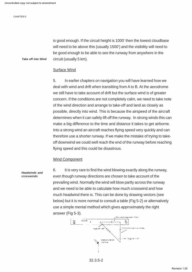
6. It is very rare to find the wind blowing exactly along the runway,even though runway directions are chosen to take account of theprevailing wind. Normally the wind will blow partly across the runwayand we need to be able to calculate how much crosswind and howmuch headwind there is. This can be done by drawing vectors (seebelow) but it is more normal to consult a table (Fig 5-2) or alternativelyuse a simple mental method which gives approximately the rightanswer (Fig 5-3).
Take off into Wind
Headwinds andcrosswinds
Uncontrolled copy not subject to amendment
Revision 1.00

WEATHER
How to use the table
From Fig 5-1 the angle between the runway heading and the wind direction = 40°(angle off). To obtain the crosswind component use the top row of angles and find the40° colum - follow it down until you meet the correct windspeed row, in this case 20kts. This gives the cross wind component as 13 kts. For the headwind use the anglesat the bottom of the table.
Fig 5-2 Table showingheadwind and crosswindcomponents
Fig 5-3 The quick approximatemethod
32.3.5-3
Uncontrolled copy not subject to amendment
Revision 1.00

Shallow Fog
7. As fog starts to form in the early evening, there is often a very shallow layer,maybe only a few feet thick, close to the ground. For a pilot in the circuit, lookingdown into the layer, this is virtually invisible. This is particularly true at night, when therunway lights show clearly when directly above them. However, as the aircraft joinsthe glide slope approaching the runway, the pilot will be looking through the fog at ashallow angle. The fog will suddenly appear to be much thicker and may well preventthe aircraft from landing as the runway and/or the lights are no longer visible. Thisslant visibility can be measured and is known as Runway Visual Range (RVR). If theRVR is less than about 800 metres a safe landing will be difficult or impossible.
Precipitation
8. Precipitation is a fancy word which covers rain, sleet, snow, hail and anythingelse wet or frozen which falls from a cloud (no, not fish!). For an aircraft on the ground,rain will not be a problem so long as the aircraft does not leak. If the rain is heavyenough it might restrict visibility or flood the runway. However, if the precipitation isfrozen or the temperature at ground level is below zero, the precipitation will stick tothe airframe and cause serious problems during the take-off. Loose snow can bebrushed off an airframe but once it is stuck to the surface it has to be treated with de-icing fluid. This is not always successful so the decision as to whether to take-off inthese conditions can be critical.
Airborne Hazards
9. Apart from thunderstorms, which are dealt with in the next ACP, icing is stillthe major problem with the weather once in the air. Even in VMC, icing can form onan airframe at certain temperatures, especially when flying a cold aircraft through rainwhich is only just above freezing point.
Icing
10. Why should icing be such a problem? In a car the main problem on a frostymorning is the frozen windscreen. In an aircraft this is easily cured by heating thewindscreen. But you cannot heat the whole of the airframe and so, as ice sticks to
CHAPTER 5
32.3.5-4
Uncontrolled copy not subject to amendment
Revision 1.00
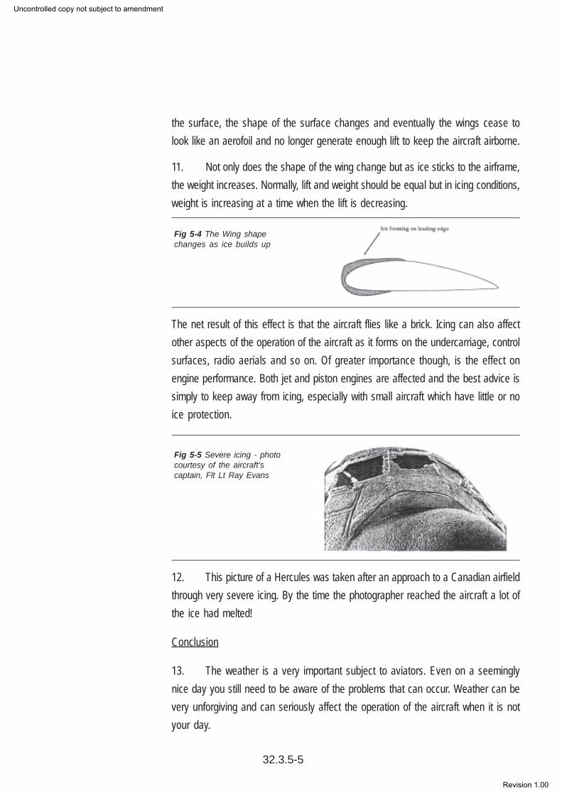
the surface, the shape of the surface changes and eventually the wings cease tolook like an aerofoil and no longer generate enough lift to keep the aircraft airborne.
11. Not only does the shape of the wing change but as ice sticks to the airframe,the weight increases. Normally, lift and weight should be equal but in icing conditions,weight is increasing at a time when the lift is decreasing.
The net result of this effect is that the aircraft flies like a brick. Icing can also affectother aspects of the operation of the aircraft as it forms on the undercarriage, controlsurfaces, radio aerials and so on. Of greater importance though, is the effect onengine performance. Both jet and piston engines are affected and the best advice issimply to keep away from icing, especially with small aircraft which have little or noice protection.
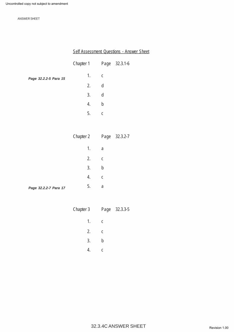
12. This picture of a Hercules was taken after an approach to a Canadian airfieldthrough very severe icing. By the time the photographer reached the aircraft a lot ofthe ice had melted!
Conclusion
13. The weather is a very important subject to aviators. Even on a seeminglynice day you still need to be aware of the problems that can occur. Weather can bevery unforgiving and can seriously affect the operation of the aircraft when it is notyour day.
Fig 5-4 The Wing shapechanges as ice builds up
Fig 5-5 Severe icing - photocourtesy of the aircraft’scaptain, Flt Lt Ray Evans
32.3.5-5
Uncontrolled copy not subject to amendment
Revision 1.00

CHAPTER 5
32.3.5-6
Self Assessment Questions
1. What do the initials VMC stand for?
a. Visual Meteorological Conditions
b. Verbal Meteorological Conditionsc. Visual Metric Conditions
d. Verbal Metric Conditions
2. An aircraft should always take off into wind to:
a. Increase the length of take off run
b. Decrease the length of take off runc. Increase ground speed at take off
d. Reduce air speed at take off
3. While attempting to land on runway 09 (heading of 90°) a pilot is informed of asurface wind blowing at 25 kts on a heading of 140°. Using the table in Fig 5-2 find thestrength of the cross wind.
a. 16 kts
b. 19 ktsc. 22 kts
d. 23 kts
4. Why is icing such a problem for aircraft?
a. De-icing is expensive and time consuming
b. The aerofoil shape of wings is spoiled - decreasing liftc. The aircraft has to fly slower due to poor visibility
d. More power is required to keep the inside of the aircraft warm
4. Rain, sleet, snow and hail are collectively known as:
a. Participation
b. IMCc. Precipitation
d. VMC
Uncontrolled copy not subject to amendment
Revision 1.00

AIR NAVIGATIONDISTANCE
1. Distance on the Earth’s surface may be expressed in one of the following three units:
The Nautical Mile
The Statute Mile, and
The Kilometre.
2. To achieve standardisation of units, the Systeme International d’Unités, abbreviated to SI Units, introduced themetre as the basic unit of length. At first sight, this implies that the kilometre should take the place of the nautical mile.However, this was not accepted as a rational proposal, mainly due to the fact that the kilometre is not related to thesexagesimal system of measurement of angles (a system based on the number 60), and since navigation is greatlyconcerned with angular measurement, the impracticalities of the proposal led to the retention of the nautical mile. It isappropriate therefore to clearly define all three units.
NAUTICAL MILE
3. A nautical mile is the length of arc of a great circle subtended by an angle of one minute at the centre of the Earth.
4. In effect, this means that an arc of the surface of the Earth which is subtended by an angle of one degree at theEarth’s centre, contains 60 nautical miles. Such a unit of distance for navigational purposes has an obvious advantageover a unit of length such as the land mile. It means, for example, that the distance between the Equator and either polewill be 90° x 60 nautical miles, since the angular distance is 90° and there are 60 minutes within each degree. Similarlythe distance around the Equator will be 360° x 60, or 21,600 nautical miles.
STATUTE MILE
5. The statute mile, or land mile, was derived from the Roman mile, a unit of 1000 Roman paces, the word comingfrom the Latin mille, meaning thousand. This mile was an arbitrary measure, and not related to the size of the Earth.
6. The statute mile is a unit of 5280 ft, the foot being one third of the arbitrary unit of length known as the yard.
KILOMETRE
7. A kilometre is 1/10,000 part of the distance between the equator and either pole.This unit has the merit that it isrelated to the size of the Earth, and would appear to be a useful one in navigation. It is not, however, related to the angularmeasuremet of 60 minutes per degree, or 90 degrees to the right angle, and is not ideally suited to replace the nautical mile© although it is gradually replacing the statute mile. A kilometre is accepted to be equivalent to 3280 ft. There are 1000metres in 1 kilometre.
SPEED
8. Speed is a rate of change of distance, and since there are three units of distance there are also three units ofspeed. They are (i) the Knot, which refers to nautical miles per hour,(ii) mph, which refers to statute miles per hour, and
(iii) kph, which refers to kilometres per hour.
32.3.1a notes
CHAPTER 1
Page 32.3.1-1 Para 2
INSTRUCTOR’S GUIDE
Page 32.3.1-2 Para 5
INSTRUCTOR’S GUIDE
Uncontrolled copy not subject to amendment
Revision 1.00

CHAPTER1
CHAPTER 1
32.3.1b notes
Aircraft speed is normally measured in the maritime tradition using the knot, although at speeds approaching, or beyond,the speed of sound another important units needs to be added. This unit is the “Mach” number.
9. The mach number relates the aircraft’s speed to the local speed of sound. It may be more precisely defined asthe ratio of the speed of the aircraft through the air, to the speed of sound in the aircraft’s vicinity.
This is shown in the following formula:
Mach Number = True Air Speed Speed of Sound
10. Simply, if an aircraft is flying at half the speed of sound, then it will have a mach number of 0.5.
11. The speed of sound varies according to the temperature surrounding the aircraft. At high level, wheretemperature is low, the speed of sound is less than at sea level, so that the mach meter is designed to take care of two
variables - the variation of aircraft speed, and the variation of the speed of sound.
1° = 60 nm
therefore
10° x 60 = 600 nm
1’ = 1 nm
so 55’ = 55 nm
TOTAL = 655 nm
AERONAUTICAL CHARTS
A map, or chart, is primarily intended to portray sections of the Earth’s surface on a flat sheet of paper. Themanner in which meridians and parallels are drawn, and the information overprinted on the surface dependson the purpose of the map. An atlas for example may need to portray large areas with the locality of certainfeatures clearly indicated. Its purpose is usually to give geographical information, and to do this, the cartographermay show parallels and meridians as straight parallel lines which lie at right angles to one another, or, he mayshow meridians as converging straight lines and parallels as arcs of concentric circles centred on the nearerpole. If the atlas fails to accurately represent angles correctly over the whole area, then, quite apart from thesmall scale being used, it would not form a suitable projection of the Earth’s surface to be useful for navigationalpurposes. The requirements of navigational charts vary however according to their particular application.
It is important now to distinguish clearly between the words “projection”, “chart”, and “map”, since thesewords are frequently used in this chapter and elsewhere.
A projection is an arrangement on a flat sheet of paper, of a graticule of meridians and parallels which areassumed to be on the Earth’s surface. All maps and charts are therefore projections of one sort or another.
Uncontrolled copy not subject to amendment
Revision 1.00

INSTRUCTOR’S GUIDE
A chart is a projection which carries very little topographical detail and which is mainly used for navigational plotting.
A map is a projection over which are printed details of topography, culture and other geographical information.
THE KNOT
The unit of measurement of a vessel’s speed, corresponding to one nautical mile per hour. The knot originated from sailingships who measured their speed by attaching a float to the end of a rope which had knots tied every 7 fathoms (12.8m)along its length. The float was then lowered into the water and the number of knots paid out in 30 seconds was the speed
of the ship.
CHAPTER 1
32.3.1c NOTES
Uncontrolled copy not subject to amendment
Revision 1.00

CHAPTER 1
32.3.1d NOTES
Uncontrolled copy not subject to amendment
Revision 1.00

32.3.2a NOTES
Page 32.3.2-1 Para 1
Page 32.3.2-1 Para 3
CHAPTER 2
INSTRUCTOR’S GUIDE
Today, the modern air navigator is assisted in his work by a large back up of instrumentation and equipment which provideinformation of height, speed, direction, distance flown, distance to fly, track guidance and position. Frequently, automationis used to control both the flight path and the landing procedure, and the idea of total automation from take off to landing bycomputer/data transmission to an aircraft’s automatic pilot is perfectly feasible. All these systems, however sophisticated,are nonetheless aids to navigation and as such may not always be available. It is therefore bad philosophy to be totallyreliant on the technology involved. Indeed there are many areas in the world where ground based electronic systems arenot available, and there are also many aircraft which for one reason or another do not have these aids fitted. The airnavigator must be able to cope adequately with any circumstance.
BEARING
The direction of one point from another is termed a “bearing”. Bearings may be measured from true north, magnetic north,or compass north but are normally plotted on a chart from true north.
Sometimes the direction of a point from the aircraft is measured in relation to the forward axis of the aircraft. In this casethe bearing is called a “relative bearing”. Relative bearings are measured clockwise from the forward axis of the aircraftthrough 360° and are frequently labelled with the letter (R). Thus, an object which is in line with the starboard wing of theaircraft has a relative bearing of 090(R). Similarly an object which is in line with the port wing has a relative bearing of270(R).
When the relative bearing is known, the true bearing of an object from the aircraft can be calculated and depends upon theheading of the aircraft.
The triangle of velocities
1. A velocity is a rate of change of position in a given direction, and as such it is made up of both speed anddirection. It is not correct to say that the velocity of an object is 30 knots; the speed may be 30 knots, but the velocity mustalso include a statement of the direction in which the object is moving.
2. A vector then must represent both speed and direction graphically, and is obtained by drawing a straight linewhose length is proportional to speed using a constant scale, and whose direction is determined by reference to a datumline. In air navigation the datum line is normally true north, so that in the diagram, each of the three vectors described isillustrated against the direction of true north which is assumed to run towards the top of the paper.
3. You will need protractors for these exercises.
Example 1.
An aircraft heading 090(T) at TAS 200 knots, is making good a track of 096(T) at a ground speed of 220 knots. Determinethe wind velocity.
Solution:
Draw a line from O in a direction of 090(T) to represent the aircraft heading. Mark this line with one arrow.
Using a constant scale make the length of the heading line, O to W, proportional to 200 knots
INSTRUCTOR’S GUIDE
Uncontrolled copy not subject to amendment
Revision 1.00

CHAPTER 2
32.3.2b NOTES
From O draw in the track in a direction of 096(T), and make the line, length O to V, proportional to 220 knots. Mark thisline with two arrows.
Join W to V, and measure its direction. The wind is blowing from W to V. Measure the length of the line for wind speed.
Answer: Wind Velocity = 320/30.
Example 2
An aircraft is heading 240(T) at an air speed of 250 knots. If the wind velocity is 140/50, determine the track made goodand ground speed.
Solution:
Draw a line from O in a direction 240(T) and of length proportional to 250 knots. Mark the point W at the end of the line.Mark this line with one arrow.
From W draw a line in a direction of 320(T) to the point V which is at a distance corresponding to 50 knots of the speed scalegiven. This is the wind velocity and should be marked with three arrows from W to V. Notice the direction of the line isfound from 140
Join O to V. Measure the direction from O to V to give the track made good. Mark the line with two arrows. Measure
the length of the line to find the ground speed.
CHAPTER 2
Uncontrolled copy not subject to amendment
Revision 1.00

Answer : Track made good is 251 (T) and ground speed 264 knots.
The navigation computer
In the previous chapters the graphical construction of the triangle of velocities was described in order to solve some of thefundamental problems presented in air navigation. In practice however, a navigator should avoid wherever possiblecarrying out time wasting calculations, and in order to do this he is helped by a purpose-built mechanical aid known as aNavigation Computer. The navigation computer is virtually standardized in design, and is used to solve more than simplythe triangle of velocities. On the reverse of the computer there is a circular slide rule capable of solving general arithmeticalproblems, and in particular those which are directly concerned with the general business of navigation. There are a varietyof different navigation computers on the market, but they all fall fundamentally into the same physical appearance with minor
modifications or additions to suit particular aircraft requirements.
Page 32.3.2-6 Para 18
CHAPTER 2
32.3.2c NOTES
INSTRUCTOR’S GUIDE
Uncontrolled copy not subject to amendment
Revision 1.00

CHAPTER3
32.3.2d NOTES
Uncontrolled copy not subject to amendment
Revision 1.00

CHAPTER 3
INSTRUCTOR’S GUIDE
INSTRUCTOR’S GUIDE
In-Flight Heading Corrections - 1-in-60 Rule
However accurately the heading may have been calculated and however carefully the pilot may steer the aircraft awind velocity can often prove different to that forecast. Also, winds can change over quite short distances, particularlywhile flying from coastal regions to a position inland or vice versa.
The ability to estimate the number of degrees off track (ie Track Error) and then determine what change of heading mustbe made (a) to fly the aircraft back on track, or (b) to reach the destination from the present, off-track position, is ofobvious value to the pilot. Technique adopted is a simple one known as the 1-in-60 rule.
Where cadets find difficulty with simple proportions ie converting the velocity triangle into a triangle with one side = 60 -try this:
The triangles ABE and ACD are similar so;
4 x20 60
therefore, x = 4 x 60
20
Since the 1 in 60 rule states that after 60 nm x = track error in degrees
Track Error in degrees = x 60
Similarly: Closing angle = x 60
Page 32.3.3-1 Para 5
Distance off track
Distance Travelled
Distance off track
Distance remaining
32.3.3a NOTES
Uncontrolled copy not subject to amendment
Revision 1.00

32.3.3b NOTES
Uncontrolled copy not subject to amendment
Revision 1.00

CHAPTER 4
Page 32.3.4-3 Para 6
INSTRUCTOR’S GUIDE
Gyroscope
1. The term gyroscope is commonly applied to spherical, wheel-shaped bodies that are universally mounted tobe free to rotate in any direction. One fundamental property they exhibit is gyroscopic inertia or rigidity in space whichmeans that a spinning wheel of a gyroscope, tends to continue to rotate in the same plane about the same axis in space,even though its supporting frame may move.
2. An example of this is the rifle bullet that, because it spins in flight, exhibits gyroscopic inertia, tending to maintaina straighter line of flight than it would if not rotating. Rigidity in space can best be demonstrated, however, by a modelgyroscope consisting of a flywheel supported in rings in such a way that the axle of the flywheel can assume any anglein space. When the flywheel is spinning, the model can be moved about, tipped, or turned in any direction, but the flywheelwill maintain its original plane of rotation.
3. Gyroscopes constitute an important part of automatic-navigation or inertial-guidance systems in aircraft, guidedmissiles, rockets, ships and submarines. In these systems, inertial guidance equipment comprises of gyroscopes andaccelerometers that continuously calculate exact speed and direction of the craft in motion. These signals are fed into acomputer, which records and compensates for course aberrations.
4. More advanced systems obtain guidance from laser gyros, which are not really inertial devices but insteadmeasure changes in counterrotating beams of laser light caused by changes in craft direction.
Magnetic Limitations
As a compass needle approaches the magnetic poles of the earth the angle of dip increases to such an extent that it makesthe instrument unusable. The angle of Dip is about 70° to the horizontal in England and 90° when at magnetic north.
32.3.4a NOTES
Uncontrolled copy not subject to amendment
Revision 1.00
ANSWER SHEET
Self Assessment Questions - Answer Sheet
Chapter 1 Page 32.3.1-6
1. c
2. d
3. d
4. b
5. c
Chapter 2 Page 32.3.2-7
1. a
2. c
3. b
4. c
5. a
Chapter 3 Page 32.3.3-5
1. c
2. c
3. b
4. c
Page 32.2.2-5 Para 15
Page 32.2.2-7 Para 17
32.3.4C ANSWER SHEET
Uncontrolled copy not subject to amendment
Revision 1.00

Self Assessment Questions - Answer Sheet cont....
Chapter 4 Page 32.3.4-6
1. c
2. b
3. a
4. b
Chapter 5 Page 32.3.5-6
1. a
2. b
3. b
4. b
5. c
32.3.4C ANSWER SHEET
ANSWER SHEET
Uncontrolled copy not subject to amendment
Revision 1.00


