Embed Size (px)
Citation preview
Variational formulation of the radiation impedance ofabsorbing patches in finite rooms
D. Holmberg, P. Hammer and E. Nilsson
Department of Engineering Acoustics, Lund University, LTH, P.O.Box 118, SE221 00 Lund, Sweden
The effect of splitting absorbers into different patches in order to improve their sound absorbing performance is investigated. Anumerical evaluation of the impact an alteration of radiation impedance,Zr , has on the statistical absorption coefficient,αstat, is madeby means of variational analysis. Implications of an alternative definition ofαstat is analysed in connection with the ordinary definitionand their application in room acoustics.
INTRODUCTION
The shape of absorbers and their interaction has beenof interest for researchers for a long time. An importantdrawback is that most approaches assume infinite struc-tures. Arbitrary shapes of structures can be handled witha variational technique developed by Morse in e.g. [1].The radiation impedance for various (periodic) patternsof absorbing patches is treated by the authors [2]. In thispaper radiation impedance is calculated in order to obtainthe corresponding statistical absorption coefficient. Theresulting formulations are valid under the assumption thatthe driving field is sufficiently homogeneous over the var-ious surfaces.
FORMULATION OF THE PROBLEM
It is has been claimed that, in order to increase thesound absorption, a group of sound absorbers should notbe placed together but preferably be scattered out whenmounted in a room. The only parameter that is changed,and relevant for the sound absorption, is the radiationimpedance. A variational formulation of the radiationimpedanceZr for periodic patterns of absorbing patchesis [2]:
Zr =ik
∑S∑i, j
ZS0
ZS
e−ikReikx,yx,y
2πRdS0dS (1)
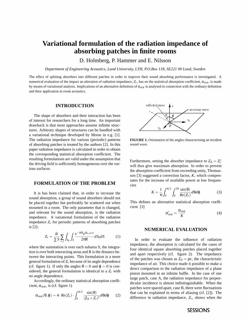
where the summation is over each subarea S, the integra-tion is over both interacting areas and R is the distance be-tween the interacting points. This formulation is a moregeneral formulation ofZr because of its angle dependence(cf. figure 1). If only the anglesθ = 0 andϕ = 0 is con-sidered, the general formulation is identical to aZr withno angle dependence.
Accordingly, the ordinary statistical absorption coeffi-cient,αstat, is (cf. figure 1)
αstat(θ,ϕ) = 4·Re(Zr) ·Z π/2
0
sin(θ)|ZA +Zr |2
dθdϕ (2)
FIGURE 1. Orientation of the angles characterising an incidentsound wave.
Furthermore, setting the absorber impedance toZA = Z∗rwill thus give maximum absorption. In order to preventthe absorption coefficient from exceeding unity, Thomas-son [3] suggested a correction factor,K, which compen-sates for the increase of available power at low frequen-cies
K =1π
Z π/2
0
Z 2π
0
sin(θ)Re(Zr)
dθdϕ (3)
This defines an alternative statistical absorption coeffi-cient [3]
α′stat =αstat
K(4)
NUMERICAL EVALUATION
In order to evaluate the influence of radiationimpedance, the absorption is calculated for the cases offour identical square absorbing patches placed togetherand apart respectively (cf. figure 2). The impedanceof the patches was chosen asZA = ρc, the characteristicimpedance of air. This choice made it possible to make adirect comparison to the radiation impedance of a planepiston mounted in an infinite baffle. In the case of onelarge patch, case A, the radiation impedance for perpen-dicular incidence is almost indistinguishable. When thepatches were spaced apart, case B, there were fluctuationsthat can be explained in terms of aliasing (cf. [2]). Thedifference in radiation impedance,Zr , shows when the
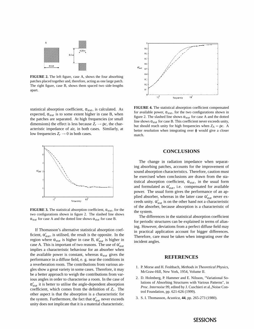
FIGURE 2. The left figure, case A, shows the four absorbingpatches placed together and, therefore, acting as one large patch.The right figure, case B, shows them spaced two side-lengthsapart.
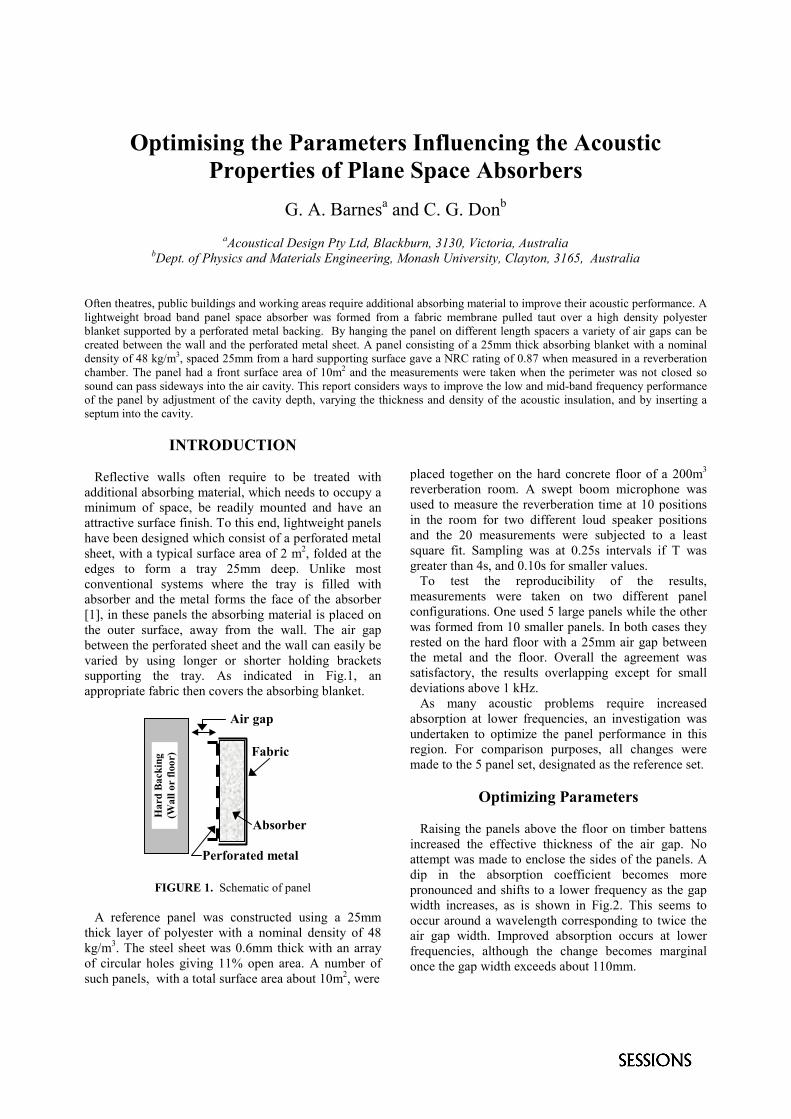
statistical absorption coefficient,αstat, is calculated. Asexpected,αstat is to some extent higher in case B, whenthe patches are separated. At high frequencies (or smalldimensions) the effect is less becauseZr → ρc, the char-acteristic impedance of air, in both cases. Similarly, atlow frequenciesZr → 0 in both cases.
FIGURE 3. The statistical absorption coefficient,αstat, for thetwo configurations shown in figure 2. The slashed line showsαstat for case A and the dotted line showsαstat for case B.
If Thomasson’s alternative statistical absorption coef-ficient, α′stat, is utilised, the result is the opposite. In theregion whereαstat is higher in case B,α′stat is higher incase A. This is important of two reasons. The use ofα′statimplies a characteristic behaviour for an absorber whenthe available power is constant, whereasαstat gives theperformance in a diffuse field, e. g. near the conditions ina reverberation room. The contributions from various an-gles show a great variety in some cases. Therefore, it maybe a better approach to weigh the contributions from var-ious angles in order to characterise a room. In the case ofα′stat it is better to utilise the angle-dependent absorptioncoefficient, which comes from the definition ofZr . Theother aspect is that the absorption is a characteristic forthe system. Furthermore, the fact thatα′stat never exceedsunity does not implicate that it is a material characteristic.
FIGURE 4. The statistical absorption coefficient compensatedfor available power,αstat, for the two configurations shown infigure 2. The slashed line showsαstat for case A and the dottedline showsαstat for case B. This coefficient never exceeds unity,but should reach unity for high frequencies whenZA = ρc. Abetter resolution when integrating overϕ would give a closermatch.
CONCLUSIONS
The change in radiation impedance when separat-ing absorbing patches, accounts for the improvement ofsound absorption characteristics. Therefore, caution mustbe exercised when conclusions are drawn from the sta-tistical absorption coefficient,αstat, in the usual formand formulated asα′stat, i.e. compensated for availablepower. The usual form gives the performance of an ap-plied absorber, whereas in the latter caseα′stat never ex-ceeds unity.α′stat is on the other hand not a characteristicof the absorber, because absorption is a characteristic ofthe system.
The differences in the statistical absorption coefficientfor periodic structures can be explained in terms of alias-ing. However, deviations from a perfect diffuse field mayin practical application account for bigger differences.Therefore, care must be taken when integrating over theincident angles.
REFERENCES
1. P. Morse and H. Feshbach,Methods in Theoretical Physics,McGraw-Hill, New York, 1954, Volume II.
2. D. Holmberg, P. Hammer and E. Nilsson, "Variational So-lutions of Absorbing Structures with Various Patterns", inProc. Internoise 99, edited by J. Cuschieri et al.,Noise Con-trol Foundation, pp. 621-626 (1999).
3. S. I. Thomasson,Acustica, 44, pp. 265-273 (1980).
Optimising the Parameters Influencing the AcousticProperties of Plane Space Absorbers
G. A. Barnesa and C. G. Donb
aAcoustical Design Pty Ltd, Blackburn, 3130, Victoria, AustraliabDept. of Physics and Materials Engineering, Monash University, Clayton, 3165, Australia
Often theatres, public buildings and working areas require additional absorbing material to improve their acoustic performance. Alightweight broad band panel space absorber was formed from a fabric membrane pulled taut over a high density polyesterblanket supported by a perforated metal backing. By hanging the panel on different length spacers a variety of air gaps can becreated between the wall and the perforated metal sheet. A panel consisting of a 25mm thick absorbing blanket with a nominaldensity of 48 kg/m3, spaced 25mm from a hard supporting surface gave a NRC rating of 0.87 when measured in a reverberationchamber. The panel had a front surface area of 10m2 and the measurements were taken when the perimeter was not closed sosound can pass sideways into the air cavity. This report considers ways to improve the low and mid-band frequency performanceof the panel by adjustment of the cavity depth, varying the thickness and density of the acoustic insulation, and by inserting aseptum into the cavity.
INTRODUCTION
Reflective walls often require to be treated withadditional absorbing material, which needs to occupy aminimum of space, be readily mounted and have anattractive surface finish. To this end, lightweight panelshave been designed which consist of a perforated metalsheet, with a typical surface area of 2 m2, folded at theedges to form a tray 25mm deep. Unlike mostconventional systems where the tray is filled withabsorber and the metal forms the face of the absorber[1], in these panels the absorbing material is placed onthe outer surface, away from the wall. The air gapbetween the perforated sheet and the wall can easily bevaried by using longer or shorter holding bracketssupporting the tray. As indicated in Fig.1, anappropriate fabric then covers the absorbing blanket.
FIGURE 1. Schematic of panel
A reference panel was constructed using a 25mmthick layer of polyester with a nominal density of 48kg/m3. The steel sheet was 0.6mm thick with an arrayof circular holes giving 11% open area. A number ofsuch panels, with a total surface area about 10m2, were
placed together on the hard concrete floor of a 200m3
reverberation room. A swept boom microphone wasused to measure the reverberation time at 10 positionsin the room for two different loud speaker positionsand the 20 measurements were subjected to a leastsquare fit. Sampling was at 0.25s intervals if T wasgreater than 4s, and 0.10s for smaller values. To test the reproducibility of the results,measurements were taken on two different panelconfigurations. One used 5 large panels while the otherwas formed from 10 smaller panels. In both cases theyrested on the hard floor with a 25mm air gap betweenthe metal and the floor. Overall the agreement wassatisfactory, the results overlapping except for smalldeviations above 1 kHz. As many acoustic problems require increasedabsorption at lower frequencies, an investigation wasundertaken to optimize the panel performance in thisregion. For comparison purposes, all changes weremade to the 5 panel set, designated as the reference set.
Optimizing Parameters
Raising the panels above the floor on timber battensincreased the effective thickness of the air gap. Noattempt was made to enclose the sides of the panels. Adip in the absorption coefficient becomes morepronounced and shifts to a lower frequency as the gapwidth increases, as is shown in Fig.2. This seems tooccur around a wavelength corresponding to twice theair gap width. Improved absorption occurs at lowerfrequencies, although the change becomes marginalonce the gap width exceeds about 110mm.
Har
d B
acki
ng(W
all o
r flo
or)
Perforated metal
Air gap
Absorber
Fabric
FIGURE 2. Effect of changing thickness of air gap behindperforated metal sheet
The use of absorbent blankets with differentthickness and density is shown in Fig.3. A less denseblanket of the same thickness has reduced highfrequency characteristics while the more expensiveoption of doubling the thickness of absorber produces asignificant improvement, especially at lowerfrequencies.
FIGURE 3. Use of different absorbing blankets. Density oftype 1 is 48kg m-3, type 2 is 18kg m-3.
This improvement is achieved by the panelapparently having � exceeding unity above 500 Hz.The 50mm blanket has the greater absorptionespecially at lower frequencies, however, it may not beimmediately obvious why � increases so markedly. Sabine’s formula allows the determination of theeffective absorption coefficient, �, of a material withsurface area Sp placed in a reverberation chamber.When calculating the above results Sp was taken to bethe top face area of the panels. In practice, however,some of the sound is absorbed by the surface facing thefloor. If the absorption coefficient of just the acousticblanket is �o, then the effective absorbing area of thepanels, Sx, can be found from �Sp = �oSx. The ratioSx/Sp is a measure of the effectiveness of the backsurface as an absorber, being unity or less when thelatter plays no part in the absorption. Table 1 lists this
ratio, averaged from the 25mm and 50mm type 1 data,at different frequencies. It is apparent that below about250 Hz the back surface has little effect, as thesewavelengths do not penetrate around the edge of thepanels. By contrast, above 250Hz the back surface is asignificant absorber.
Table 1. Effect of back surface as an absorberFreq.(Hz) 125 250 500 1000 2000
Sx/Sp 0.94 1.07 1.37 1.44 1.35
The effect of insertion of a septum is demonstrated inFig.4. In this case the septum was formed by placing a3mm thick sheet of plywood 70mm from the hardbacking with the metal panel a further 60mm away.Thus the septum was essentially near the centre of a130mm air gap. The 1.8m x 1.2m plywood sheet wassupported only around its edges, so the centre area wasfree to vibrate. At frequencies above 300Hz the systemacts like a single 60mm air gap. A significantimprovement at the lower frequencies is achieved bythe insertion of the septum compared to the empty130mm air gap.
FIGURE 4. Effect of insertion of a septum
CONCLUSION
A panel with absorber on top of the perforated metalsheet can cause the effective absorption coefficient toexceed unity by a significant factor and permits the airgap thickness to be easily adjusted. Insertion of aseptum produced essentially the same low frequencyresults as using a thick, more expensive, acousticblanket. At higher frequencies the system behaved likea single reduced depth air space.
ACHNOWLEDGEMENT
The authors wish to thank Mr. P Dale for hisassistance when using the Royal Melbourne Institute ofTechnology reverberation room.
REFERENCE1. Davern, W.A. Applied Acoustics, 10, 85-112 (1977).
0.00
0.20
0.40
0.60
0.80
1.00
1.20
1.40
100 160 250 400 630 1000 1600 2500 4000
Frequency (Hz)
Abs
orpt
ion
Coe
ffici
ent
130mm airgap
115mm airgap
70mm airgap
25mm airgap
0.00
0.20
0.40
0.60
0.80
1.00
1.20
1.40
100 160 250 400 630 1000 1600 2500 4000
Frequency (Hz)
Abs
orpt
ion
Coe
ffici
ent
130mm air gap with septuminserted
130mm air gap
70mm air gap
0.00
0.20
0.40
0.60
0.80
1.00
1.20
1.40
1.60
100 160 250 400 630 1000 1600 2500 4000
Frequency (Hz)
Abs
orpt
ion
Coe
ffici
ent
25mm thick absorber, type 1
50mm thick absorber, type 1
25mm absorber, type 2
Strip AbsorbersJ.P. Parkinsona J.R. Pearsea M.D. Latimerb
aDepartment of Mechanical Engineering, University of Canterbury, Christchurch, New ZealandbD.G. Latimer and Associates Ltd, P O Box 12-032, Christchurch, New Zealand
An experimental study has been carried out on the use of alternating strips of materials to produce wideband absorbers. Theabsorption of a film faced foam was successfully combined with the absorption of a plain foam by combining the two materialsin strips. Excess absorption (more than the average of the constituent strips' absorption) was found in each case. The stripabsorber comprised of foam and film faced foam had greater wideband absorption than a similar absorber with the materialslayered parallel to the backing surface (film sandwiched between two layers of foam) at 24 mm total thickness but not at 48mm thickness.
INTRODUCTION
Multilayer acoustic absorbers have historically beendeveloped with the aim of attaining high widebandabsorption. A rigid porous layer in combination with a thinporous sheet was modelled by Ingard [1]. It wasfound that adding a thin porous cover screen gave asignificant increase in low frequency absorption. Takahashi [2] studied the phenomenon of excesssound absorption of periodically arranged flatsurfaces. Excess sound absorption (more than theaverage of each material’s absorption) occurred in allcases of periodically arranged surfaces. The work described here was based on the idea ofexcess sound absorption as described by Takahashi[2]. The aim was to experimentally determinewhether the phenomenon of excess absorption appliesto impervious film faced foams, the objective being tocombine the relatively high absorption in lowfrequencies of the film faced foam with the highfrequency absorption of plain foam. Comparisons aremade with the same thickness of foam but with thefilm sandwiched between the foam layers as in atraditional multilayered absorber.
MEASUREMENTS
A Bruel and Kjaer 2260 sound analyser was used tomeasure reverberation times in a reverberation room(volume 217 m3) with and without the test specimenpresent. A total of 12 reverberation decays weremeasured at a variety of microphone positions andloud-speaker locations for each absorber.Repeatability tests indicated that the absorptioncoefficients had an uncertainty of ± 1.5% in thefrequency range from 250 to 5000 Hz.
The foam used was a combustion modified partiallyreticulated polyurethane foam of the polyether type(CMSG). It typically has 36-38 cells / 25mm and abulk density of 43 kg/m3. The film used wasMylar™, a thin (100 �m) metallised polyester filmwith a surface density of 140 g/m2. Test specimenscomprised four sheets of 1.2 x 2.4 m absorber.
RESULTS
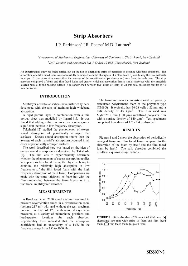
Figures 1 and 2 show the absorption of periodicallyarranged foam and film faced foam compared to theabsorption of the foam by itself and the film facedfoam by itself. The strip absorber combined theresults in a quasi-average fashion.
0.0
0.2
0.4
0.6
0.8
1.0
1.2
100
160
250
400
630
1000
1600
2500
4000
Frequency (Hz)
Abso
rptio
n co
effic
ient
FIGURE 1. Strip absorber of 24 mm total thickness; [�]alternating 150 mm wide strips of foam and film facedfoam, [�] film faced foam, [o] plain foam.
0.0
0.2
0.4
0.6
0.8
1.0
1.210
0
160
250
400
630
1000
1600
2500
4000
Frequency (Hz)
Abso
rptio
n co
effic
ient
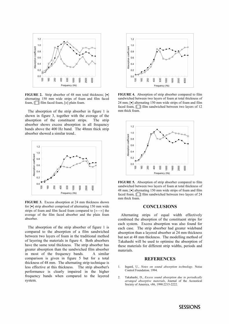
FIGURE 2. Strip absorber of 48 mm total thickness; [�]alternating 150 mm wide strips of foam and film facedfoam, [�] film faced foam, [o] plain foam.
The absorption of the strip absorber in figure 1 isshown in figure 3, together with the average of theabsorption of the constituent strips. The stripabsorber shows excess absorption in all frequencybands above the 400 Hz band. The 48mm thick stripabsorber showed a similar trend..
0.0
0.2
0.4
0.6
0.8
1.0
1.2
100
160
250
400
630
1000
1600
2500
4000
Frequency (Hz)
Abso
rptio
n co
effic
ient
FIGURE 3. Excess absorption at 24 mm thickness shownfor [�] strip absorber comprised of alternating 150 mm widestrips of foam and film faced foam compared to [���] theaverage of the film faced absorber and the plain foamabsorber.
The absorption of the strip absorber of figure 1 iscompared to the absorption of a film sandwichedbetween two layers of foam in the traditional methodof layering the materials in figure 4. Both absorbershave the same total thickness. The strip absorber hasgreater absorption than the sandwiched film absorberin most of the frequency bands. A similarcomparison is given in figure 5 but for a totalthickness of 48 mm. The alternating strip technique isless effective at this thickness. The strip absorber'sperformance is clearly impaired in the higherfrequency bands when compared to the layeredsystem.
0.0
0.2
0.4
0.6
0.8
1.0
1.2
100
160
250
400
630
1000
1600
2500
4000
Frequency (Hz)
Abso
rptio
n co
effic
ient
FIGURE 4. Absorption of strip absorber compared to filmsandwiched between two layers of foam at total thickness of24 mm; [�] alternating 150 mm wide strips of foam and filmfaced foam, [�] film sandwiched between two layers of 12mm thick foam.
0.0
0.2
0.4
0.6
0.8
1.0
1.2
100
160
250
400
630
1000
1600
2500
4000
Frequency (Hz)
Abso
rptio
n co
effic
ient
FIGURE 5. Absorption of strip absorber compared to filmsandwiched between two layers of foam at total thickness of48 mm; [�] alternating 150 mm wide strips of foam and filmfaced foam, [�] film sandwiched between two layers of 24mm thick foam.
CONCLUSIONS
Alternating strips of equal width effectivelycombined the absorption of the constituent strips foreach system. Excess absorption was also found foreach case. The strip absorber had greater widebandabsorption than a layered absorber at 24 mm thicknessbut not at 48 mm thickness. The modelling method ofTakahashi will be used to optimise the absorption ofthese materials for different strip widths, periods andmaterials.
REFERENCES1. Ingard, U., Notes on sound absorption technology. Noise
Control Foundation. 1994.
2. Takahashi, D., Excess sound absorption due to periodicallyarranged absorptive materials, Journal of the AcousticalSociety of America, v86, 1990:2215-2222.
An Innovative Sound Absorption System which Fulfils theHighest of Acoustic and Aesthetic Requirements
H.D. Sulzer
Dipl. lng., BASWA AG, Baldegg Sound and Heat Absorption Company,Marmorweg 10, 6283 Baldegg, Switzerland
The newly developed BASWA®-phon absorptive system, which is seamless and looks like plaster, closes a gap in the field ofabsorptive solutions and opens up new design possibilities for builders and architects. The absorptive coefficients measured areexcellent, especially in the low frequency range, due to resonance of the microporous membrane formed by the absorptive plasterafter drying. The loss of room height is minimal, since the total thickness of the system is maximum 6 cm. Seamless surfaces ofup to 500 m2 have been installed without any problems.
INTRODUCTION
The multiple reverberation of sound waves in roomsoften creates an undesirable acoustical field, in whichmusic can become distorted and the human voice canbecome barely audible.
Reverberation occurs� in medium- and large-sized rooms,� in rooms whose boundary surfaces are hard and re-
flecting,� in domes and vaults, which are particularly sensitive,
as they tend to focus reverberation on the underlyingfloors.The usual measure to decrease reverberation consists
of the treatment of a part of the boundary surfaces withan absorptive porous layer made of juxtaposed ele-ments. Many absorptive systems are available on themarket. They are not greatly favored by building own-ers, users or architects, however, as they are notaesthetically pleasing and are difficult to integrate intonew and existing buildings. They also imply a sensitivereduction of room height and important additionalcosts.
The method presented here is suitable in most casesand adaptable to any specific surroundings. Usuallyonly the room’s ceiling is subject to treatment. Wallsand vaults can also be made absorptive, however. It hasto be emphasized that a room’s acoustics can also becorrected after construction has been completed andhigh reverberation has been established, as is the casein many historical or multi-purpose buildings.
POROUS COATING MATERIALS
A porous coating compound called BASWA-phonhas been developed, which possesses very good acous-tic qualities when applied on propriatory mineral woolpanels leading to air-flow resistance of 100-160 Rayls.
The seamless absorptive plaster, applied on site, ismade of white granules of similar size and offers asmooth but microporous surface after drying, allowingthe sound to penetrate the underlying fibrous absorp-tive panels, which have been previously glued to thesurface to be treated.
When the compound dries, a 5 mm thick membraneis formed. Its natural color is white (RAL 9002), butcoloring the compound is possible, on the conditionthat the pigment component does not exceed approxi-mately 1%. Coloring is done in the factory.
THE ACOUSTIC ABSORPTIONSPECTRUM
The BASWA-phon coating’s formulation is cali-brated in such a way that after it has dried, an extensivesystem of micro-pores is created in the 5 mm coat thathas been applied. Sound absorption takes place in thepores and in the fibrous underlying mat on account offriction between vibrating air molecules, with the resultthat sound energy is converted into heat and dissipated.This is the usual physical process which takes place inalmost all sound absorption materials available on themarket. The random distribution of the micro-poresand the coating’s three-dimensional porousness, how-ever, increases the effect when compared to standardmethods.
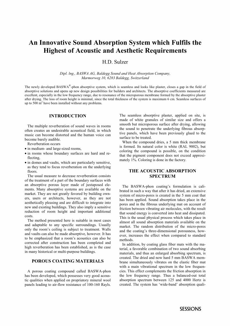
In addition, by coating glass fiber mats with the ma-terial, a favorable combination of two sound absorbingmaterials, and thus an enlarged absorbing spectrum, iscreated. The dried and now hard 5 mm BASWA mem-brane simultaneously vibrates on the elastic fiber matwith a main vibrational spectrum in the low frequen-cies. This effect complements the friction absorption inthe low frequency range. Thus a balanced-out totalabsorption spectrum between 125 and 4000 Hertz iscreated. The system has ‘wide-band’ absorption quali-
ties, a fact which is always praised again by acousti-cians (Figures 1 and 2).
The BASWA coating’s porousness remains intact
even after the intense application and smoothing pro-cedure, so that its acoustic effectiveness is largelyindependent of the site handling procedure.
Deg
ree
of so
und
abso
rptio
n �
s
Deg
ree
of so
und
abso
rptio
n �
s
Frequency f Frequency f
FIGURE 1. Sound absorption capacity of a 5 mm BASWA-phon coat on 60 mm mineral fiber boards, with the system’sdistance from the ceiling = 0 mm.
FIGURE 2. Sound absorption capacity of a 5 mm BASWA-phon coat on 60 mm mineral fiber boards, with the system’sdistance from the ceiling = 250 mm.
FROM THE MATERIAL TO THESYSTEM
As has already been mentioned, the coating com-pound is applied seamlessly to fiber mats, which inturn are stuck to the raw ceiling. Thanks to the coat-ing’s full compatibility with 3 - 6 cm thick glass fibermats architects, acousticians and building owners nowhave a new, fair-price solution to the problem of roomacoustics. It is increasingly accepted and used, parti-cularly in representative rooms such as entrance halls,bank service till halls, conference rooms, exhibitioncenters as well as in schools, hospitals, restaurants,residences, gyms and multi-purpose halls. The newsystem is particularly appreciated in the preservation ofmonuments, as the absorptive surfaces can be accom-modated within existing stucco profiles without anyproblems. The material is independent of the size andtexture of the ceiling (vaults, for example). Elementssuch as lights and fire alarms can be integrated withoutany problems.
MATERIAL AND PROCESSING
The glass fiber mats have to be glued to the rawceiling first, or to unperforated plaster boards in sus-pended ceiling systems. Following this, the joints be-tween the mats are closed with a special seam fill. Thefinal step involves sanding the base and applying the
white coating seamlessly in two operations. The mate-rial itself is supplied as a wet ready-to-use compoundin plastic buckets. Layers of BASWA-phon are appliedand have to dry during 24 to 48-hour periods (the com-pound has to dry completely), until a thickness ofapproximately 5 mm is reached. As the compoundbehaves like plaster during processing and is appliedby plasterers, it can be adapted to any shape, such asarches, vaults or walls.
CLEANING, RENOVATION
Of course you have the possibility of cleaning smokestains and fat, for example, off dirty surfaces, using aspecial solution developed by the producer.
CONCLUSIONS
With BASWA-phon, architects and acousticians havea material available for the correction of a room’sacoustics which is aesthetic in appearance and flexiblein use.
Absorption for the Control of Reverberation by UsingPerforated Gypsum and Wood Boards
J. Ramis, J. Alba ,J.M. Bravo and J.Redondo.
Departamento de Física Aplicada, Escuela Politécnica Superior de Gandia, 46730 Grao de Gandia, Spain
For the acoustics conditioning of auditoriums is very important the control of reverberation. In this work results frommeasurements of absorption coefficient for perforated gypsum and wood boards carried out in the reverberation chamber ofEPS Gandia are presented. This device could be applied for the control of reverberation in the range of medium to lowfrequencies. We analyse the influence of different kinds of porous sheets in the air cushion and the influence of others factorsthat are significant influence in the results. The results are interesting from point of view of architect that it is interested inroom boundaries with the same appearance but with different acoustical properties.
INTRODUCTION
The absorption for the control of reverberation is veryimportant speaking rooms acoustics. Porous materialare very effective sound absorbers . Their absorptioncoefficients decrease at low and medium frequencies.However, most porous sound absorptive sheets do notpresent suitable surfaces for rooms. Perforate plateswere originally introduced as acoustically transparentcovering that could be easily cleaned and painted.Figure 1b show typical configurations.
boardair
absorbent
wallboard
airabsorbent
wall
Perforate plate
FIGURE ERRORE. L'ARGOMENTOPARAMETRO È SCONOSCIUTO.. Typicalconfigurations. a) without perforation b) Withperforation
For the first configuration (figure 1-a), the resonancefrequency can be estimated by the equation
mdf 600
0 � (1)
where m is the surface density (in Kg/m2) and d the dla distance to wall (in cm). (The maximum absorption
is produced for the resonant frequency). Forconfiguration 1b (perforated plates), the maximum ofabsorption is presented for :
dLPf'
54800 � (2)
where , P is the percentage of perforation defined by:
b
a
SSP � (3)
Sa being the perforated surface and Sb the surface ofplate, and L’ is the effective length
L’ = L + 1.6a (4)
Where L is the thickness panel and a is the radiusperforation.
Only if the percentage of perforation is large enoughthe plate will be acoustically transparent. In this case,the absorption coefficient of the system and that of theabsorbent material would be roughly the same.
DETERMINATION OF ABSORPTIONCOEFFICIENT IN REVERBERATION
ROOM
The procedure followed for the determinationabsorption coefficient is described in [2]. Frommeasurements reverberation time with and withoutmaterial sample can be obtain the absorptioncoefficient of device. Limitations and uncertainly forthis method are discussed in [1] and [3].
MEASUREMENTS
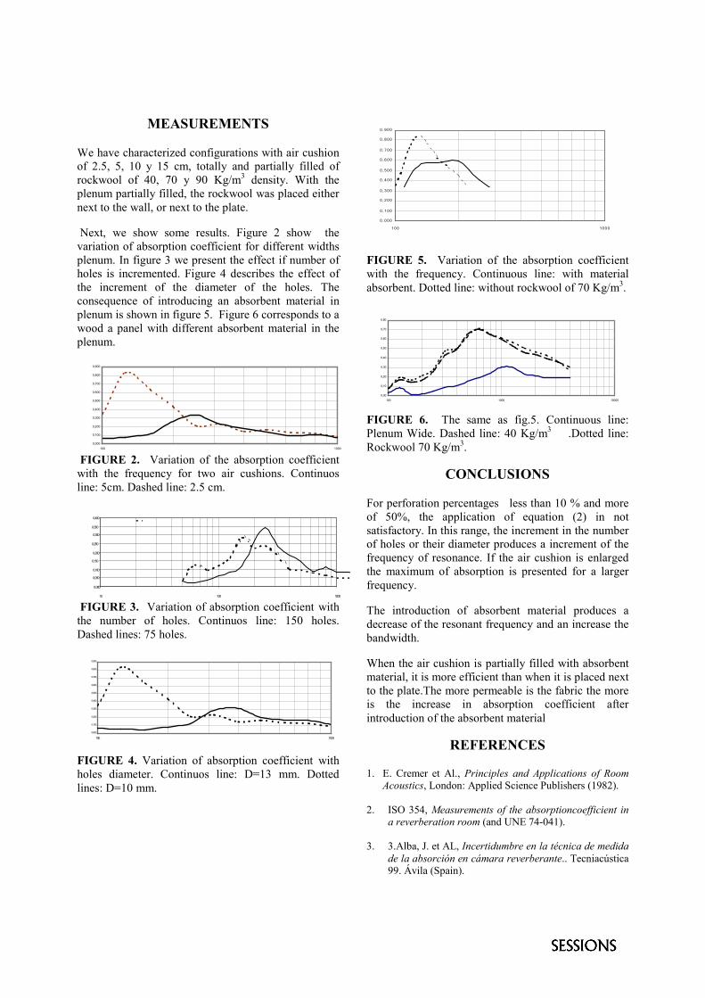
We have characterized configurations with air cushionof 2.5, 5, 10 y 15 cm, totally and partially filled ofrockwool of 40, 70 y 90 Kg/m3 density. With theplenum partially filled, the rockwool was placed eithernext to the wall, or next to the plate.
Next, we show some results. Figure 2 show thevariation of absorption coefficient for different widthsplenum. In figure 3 we present the effect if number ofholes is incremented. Figure 4 describes the effect ofthe increment of the diameter of the holes. Theconsequence of introducing an absorbent material inplenum is shown in figure 5. Figure 6 corresponds to awood a panel with different absorbent material in theplenum.
0,000
0,100
0,200
0,300
0,400
0,500
0,600
0,700
0,800
0,900
100 1000
FIGURE 2. Variation of the absorption coefficientwith the frequency for two air cushions. Continuosline: 5cm. Dashed line: 2.5 cm.
0,000
0,050
0,100
0,150
0,200
0,250
0,300
0,350
0,400
10 100 1000
FIGURE 3. Variation of absorption coefficient withthe number of holes. Continuos line: 150 holes.Dashed lines: 75 holes.
0,000
0,100
0,200
0,300
0,400
0,500
0,600
0,700
0,800
0,900
100 1000
FIGURE 4. Variation of absorption coefficient withholes diameter. Continuos line: D=13 mm. Dottedlines: D=10 mm.
0 , 0 0 0
0 , 1 0 0
0 , 2 0 0
0 , 3 0 0
0 , 4 0 0
0 , 5 0 0
0 , 6 0 0
0 , 7 0 0
0 , 8 0 0
0 , 9 0 0
1 0 0 10 0 0
FIGURE 5. Variation of the absorption coefficientwith the frequency. Continuous line: with materialabsorbent. Dotted line: without rockwool of 70 Kg/m3.
0,00
0,10
0,20
0,30
0,40
0,50
0,60
0,70
0,80
100 1000 10000
FIGURE 6. The same as fig.5. Continuous line:Plenum Wide. Dashed line: 40 Kg/m3 .Dotted line:Rockwool 70 Kg/m3.
CONCLUSIONS
For perforation percentages less than 10 % and moreof 50%, the application of equation (2) in notsatisfactory. In this range, the increment in the numberof holes or their diameter produces a increment of thefrequency of resonance. If the air cushion is enlargedthe maximum of absorption is presented for a largerfrequency.
The introduction of absorbent material produces adecrease of the resonant frequency and an increase thebandwidth.
When the air cushion is partially filled with absorbentmaterial, it is more efficient than when it is placed nextto the plate.The more permeable is the fabric the moreis the increase in absorption coefficient afterintroduction of the absorbent material
REFERENCES
1. E. Cremer et Al., Principles and Applications of RoomAcoustics, London: Applied Science Publishers (1982).
2. ISO 354, Measurements of the absorptioncoefficient ina reverberation room (and UNE 74-041).
3. 3.Alba, J. et AL, Incertidumbre en la técnica de medidade la absorción en cámara reverberante.. Tecniacústica99. Ávila (Spain).


![Process-Structure-Properties-Performance Modeling for ... · Holmberg et al. [11] and Laukkanen et al. [12] who introduced methods to address complex and realistic material microstructures](https://img.pdfslide.us/doc/110x75/606ea97c22c1db33893a8941/process-structure-properties-performance-modeling-for-holmberg-et-al-11-and.jpg)