Embed Size (px)
Citation preview
Shear strengthening of rectangular and circular concrete members using FRP
Dr Jon Shave and John Bennetts
Parsons Brinckerhoff, Redland Hill
Bristol BS6 6US
UK
Dr John Orr and Dr Antony Darby University of Bath Claverton Down
Bath BA2 7AY
UK
ABSTRACT This paper provides the background and guidance relating to the design methods proposed in The Concrete Society’s Technical Report 55 (TR55) third edition [1] for the shear strengthening of rectangular and circular reinforced concrete members using fibre composite materials. When TR55 was updated to the third edition the content was aligned with the suite of Eurocodes for structural design. There were several challenges involved in updating the shear strengthening requirements to align with BS EN 1992-1-1 [2]. In particular, the approach for shear resistance of reinforced concrete members with shear reinforcement in BS EN 1992-1-1 [2] is different in philosophy from the methods previously used in BS8110 [3] and BS5400-4 [4], since it includes a variable angle truss method. Furthermore, BS EN 1992-1-1 [2] does not provide adequate guidance on shear resistance of circular sections. This paper considers how these challenges have been addressed in TR55 [1] and provides new guidance on the design of fibre-reinforced polymer (FRP) for shear strengthening using a Eurocode-aligned approach. INTRODUCTION Background Concrete members such as columns or beams can be strengthened to give additional shear resistance using fibre-reinforced polymer (FRP) materials. The FRP strengthening often comprises a fabric wrapped around the concrete section: fully wrapped arrangements are significantly more effective than partially wrapped arrangements, due to issues of anchorage of the FRP. Alternatives to wrapping include near-surface mounted bars [5] and deep embedment bars [6], which are described further in TR55 [1]. The basic approach for the design of shear strengthening is typically based on an assumption that FRP added to the perimeter of the concrete section acts as additional shear reinforcement, and provides an additive contribution to the shear resistance of the existing structure. The design of FRP for strengthening concrete structures is covered by the Concrete Society document TR55 [1], which in its third edition has been aligned with the suite of structural Eurocodes. This alignment process has involved changes to the design process including the basis of design (BS EN 1990 [7]), load models (BS EN 1991 [8]) and concrete design (BS EN 1992 [2]). Conditions for the serviceability limit states, accidental design situations and fire, for example, are now covered in the Eurocodes in a different way from previous design standards. Furthermore the method for designing the shear resistance of shear-reinforced concrete sections is a particular example of an aspect that is
covered differently in the Eurocodes from previous standards, and this has had an impact on the alignment of the rules for designing shear strengthening in TR55.
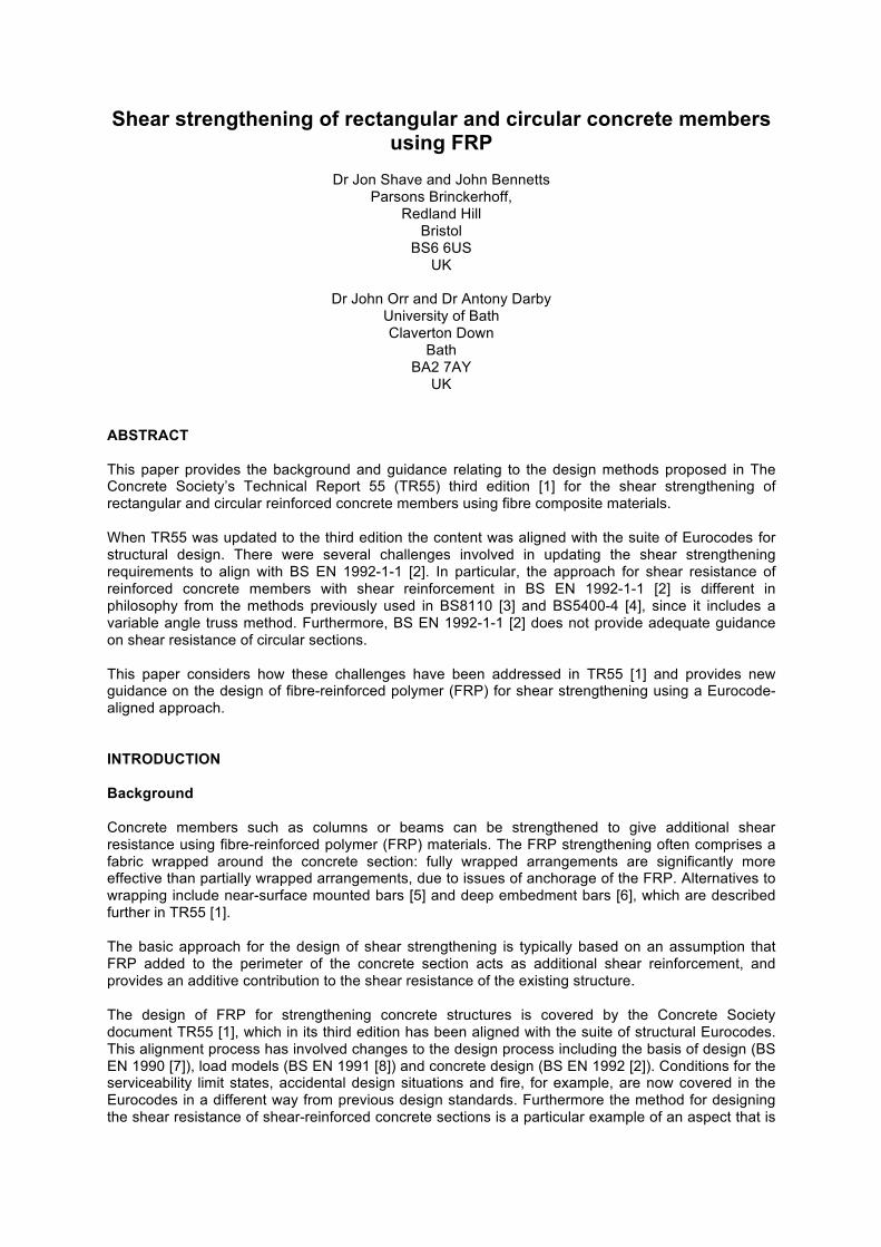
Figure 1. Strengthening concrete structures in shear using FRP
(images from University of Bath(top) and TR55(bottom)) Design models for shear resistance of shear-reinforced concrete Modelling shear in reinforced concrete using a truss analogy was first proposed by Ritter and Mörsch [9, 10]. The basic premise of the truss model is that cracked concrete in the web of the section resists shear by a diagonal uniaxial compressive stress in a concrete strut which pushes the flanges apart and causes tension in the stirrups which are then responsible for holding the section together, so the
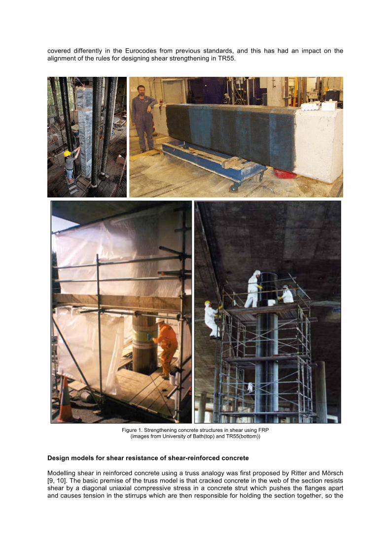
system of compressive struts and tension ties resembles a truss. The Mörsch model assumes that the angle of the compression strut from the beam axis (θ) is 45º. Based on this assumption, the required forces in the shear reinforcement may be calculated, which is the basis of the design approach. Shear strength predictions with such a model were found [11] to be conservative by a consistent value. The model was adjusted in ACI 318 [12], BS 8110-1 [3] and BS 5400 [4] to give improved correlation with test results by the addition of an empirical ‘concrete contribution’ to shear capacity. This design approach was used for many years in the UK until the introduction of Eurocodes. A different approach is taken in BS EN 1992-1-1 [2], which relies on the “variable-angle truss” model of shear resistance (see Figure 2). With this approach there is no additive “concrete contribution” to the shear resistance: the entire resistance is based on an equivalent truss model, but the angle of the truss may be flatter than 45 degrees. The designer may choose a truss angle between upper and lower limits as recommended in BS EN 1992-1-1 and defined in the National Annex.
Figure 2. The variable angle truss model. The variable angle truss model (illustrated in Figure 2) is based on an assumption that an inclined stress field develops in the concrete at an angle θ which forms an equivalent truss with transverse tension forces in the steel shear reinforcement, longitudinal tension in the steel reinforcement in the tension face, and longitudinal compression in the concrete “compression chord” located in the compressive face. The forces in the truss are calculated based on a condition of equilibrium with the applied shear force, bending moment and axial force. Then, by limiting the truss forces to those values associated with yielding of the steel or crushing of the concrete, the model provides an estimate of shear resistance. The value of the shear resistance is a function of the truss angle θ which may be chosen by the designer from a range of permissible values. A flatter strut will intersect more links and therefore give a more favourable resistance, as long as the web concrete does not crush in compression. BS EN 1992-1-1 [2] recommends allowable truss angles within the range of 21.8 and 45 degrees, which are also implemented in the UK National Annex. The lower limit of the truss angle (21.8 degrees) is intended to prevent excessive and unrealistic rotation of the principle stress in the concrete between serviceability and ultimate limit state conditions. At a serviceability level of loading there will not be shear cracks in the web and an elastic uncracked analysis would suggest that a shear force would cause a principle stress at 45 degrees to the member axis at the level of the neutral axis. As the load is increased, cracking will occur in the web, followed by yielding of the steel shear reinforcement. During this process the direction of the principle stress rotates and becomes flatter, and eventually the ultimate limit state will be reached when the structure fails. It is sensible to impose a pragmatic limit on the extent of the rotation of the stress direction that may be assumed for design, particularly because of the limited ductility of shear failures. This is the basis of the range of truss angles permitted by BS EN 1992-1-1 for reinforced concrete sections in shear. Development of shear resistance model for design of FRP strengthening When concrete is strengthened with FRP, it is generally assumed that the FRP has no ductility. This principle presents a particular challenge regarding the development of design rules for strengthening resistance, since it is important not to rely on any ductility of the FRP (even implicitly). In TR55 [1] (third edition) the objective was to develop a Eurocode-aligned design model for FRP shear strengthening that was based on the variable angle truss model as featured in BS EN 1992-1-1 [2], but that was appropriately cautious with respect to the non-ductile failure modes that can occur in FRP-strengthened members.
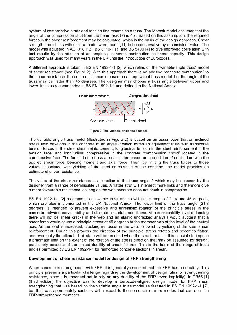
One possible approach might be to incorporate the FRP as additional tension members in the same truss model as that used for the steel reinforcement, and limit the FRP forces to their ultimate resistance values. However, such an approach would not account for the differences in ductility between the FRP and the steel, and would require a new minimum limit on the truss angle to be developed for the FRP strengthened system. In international design standards, the contribution of FRP to shear capacity in strengthening designs is most often characterised by a 45º truss model [13]. Simply limiting the minimum truss angle of the entire FRP-strengthened section to 45º would remove the requirement for rotation of the stress field between SLS and ULS conditions. However, such an approach would be excessively conservative for design. Imposing a 45º truss (cot θ = 1) reduces the contribution of the steel links by a factor of 2.5 when compared to the use of the more usual minimum truss angle of 21.8º (cot θ = 2.5). Such a reduction is potentially greater than the amount by which the section would be strengthened – resulting in a situation where the strengthened resistance would very often be less than the unstrengthened resistance. This would not be very useful for designing strengthening systems. On the other hand, allowing a truss angle in the entire FRP-strengthened section of 21.8º would not be conservative, and would imply an inappropriate degree of ductility associated with the non-ductile FRP. Furthermore, observations from testing suggest that adding FRP strengthening to a reinforced concrete section does steepen the compression strut angle at the ultimate limit state when compared to an unstrengthened element. It therefore appears that an intermediate value of the minimum truss angle is needed for an FRP-strengthened concrete member, and this limit should be set somewhere between 21.8 and 45 degrees. These observations have led to the approach underpinning the current guidance in TR55 [1] which is based on a superposition of the forces associated with two different truss systems for shear design, with one system including the steel shear reinforcement and the other system including the FRP strengthening, as summarised in Figure 3. The proposed method is consistent with that used in BS EN 1992-2 [14] for post tensioning systems (where one truss model may be used to model the passive reinforcement and a second may be used to model the active reinforcement). For each truss system, there is a uniaxial stress in the concrete in a certain direction (which may be different for the two systems). Superposition of the two systems results in a stress field with a principal stress in an intermediate direction, the angle of which may be expressed as a “weighted mean” of the angle θ for each of the two systems.
Figure 3. Superposition of trusses approach.
When applied to FRP strengthened sections, this superposition approach allows different limits on truss angle to be specified for the truss systems for the steel reinforcement and the FRP strengthening. In TR55, the FRP system is limited to a truss angle of 45 degrees (cot θ = 1), while the steel truss is permitted to have an angle of between 21.8 degrees and 45 degrees, as in BS EN 1992-1-1 [2]. The resistance associated with this method may be expressed as the sum of the resistances for each truss system. The resulting equation for resistance has the form: VRd,s,f = VRd,s + Vf (1) Where:
VRd,s,f = the shear capacity of the strengthened section VRd,s = design value of the shear force which can be sustained by the yielding shear
reinforcement (with: 1 ≤ cot θ ≤ 2.5)
Vf = shear resistance from the FRP (with: cot θ = 1) Since the existing member generally has a design shear resistance of VRd,s , the approach provides an additional shear resistance of Vf (which is based on a 45 degree truss model). So, although the superposition approach may appear novel, it results in a total resistance that has a strong similarity to the expressions in previous design codes for FRP strengthening, which generally provide an additive contribution of the FRP that is also based on a 45º truss model [13]. The form of Equation (1) is based on an implicit assumption that the steel shear reinforcement will yield before the FRP system fails. This assumption is also implicit in all other design standards for FRP strengthening. However, in principle it is possible that in some extreme cases where a larger thickness of FRP is proposed, the FRP could fail prematurely before the steel reinforcement yields. To address this concern, an additional strain check was developed for inclusion in TR55 third edition. The principle behind the additional check is to ensure that the ultimate strain in the FRP at failure is greater than the strain needed to cause yield in the steel reinforcement. For simplification, this check is based on an assumption that the strains in the FRP and the steel are equal at the ultimate limit state. This assumption would be correct if the steel and the FRP were both entirely debonded over an equal length (e.g. the depth of the member) and the crack width were uniform through the thickness of the member. It is recognised that this is a somewhat crude assumption, nevertheless the inclusion of the new design criterion is considered an important step forward that seeks to prevent premature failures of FRP designs. In addition it is also necessary to check that the concrete does not crush in compression under the combined stress of the two systems. To simplify this check (which is rarely governing in practice) a conservative approach is to calculate VRd,max using the approach in BS EN 1992-1-1 [2] based on the truss angle for the first system (including only the steel reinforcement). Since this truss angle will be shallower than for the combined system, it will give a conservative estimate of VRd,max. A similar approach may be used for checking the longitudinal tension force in the truss, where the value of ΔFtd as defined in BS EN 1992-1-1 may be conservatively based on the truss angle for the steel system alone. If needed, a less conservative estimate of VRd,max or ΔFtd may be obtained by calculating the resultant truss angle based on an analysis of the principal stress direction for the combined system. DESIGN METHOD Strengthening rectangular sections in shear Based on the approaches described in the previous section, the basic equation for design of rectangular sections in shear where the FRP and the steel reinforcement are both perpendicular to the axis of the member is given by Eq.(2):
VRd ,s, f =
Aswszfywd cotθ +
Afw
s fd f −
ns3lt ,max
⎛⎝⎜
⎞⎠⎟Efdε fse (2)
Where:
Asw = cross sectional area of steel shear reinforcement s = spacing of steel stirrups z = lever arm
fywd = design tensile strength of steel shear reinforcement θ = angle between compression strut and axis perpendicular to shear force
Afw = area of FRP for shear sf = spacing of FRP strips df = effective depth of FRP shear reinforcement ns = factor for anchorage of shear strengthening (zero for fully wrapped members)
lt,max = maximum anchorage length corresponding to Tk,max Tk,max = ultimate bond failure force
Efd = design elastic modulus of FRP εfse = effective strain in the FRP for shear strengthening
Further definition and explanation of the terms is given in TR55. The first part of the resistance equation corresponds to the truss system including the steel shear reinforcement with a truss angle of θ, while the second part corresponds to the truss system including the FRP with a truss angle of 45 degrees. Where the element is to be strengthened with FRP inclined at an angle β to a line perpendicular to the axis of the element, then the more general form of Eq.(3) is used:
VRd ,s, f =
Aswszfywd cotθ +
Afw
s fd f −
ns3lt ,max cosβ
⎛⎝⎜
⎞⎠⎟Efdε fse sinβ + cosβ( ) (3)
TR55 [1] requires that the value of εfse is limited to the minimum of:
(i) fd5.0 ε (to prevent rupture of the FRP)
(ii) ffd
ctk5.0tfε
(to prevent separation of the FRP)
(iii) 0.004 (to maintain concrete integrity) The second limit (corresponding to separation failure) has been adjusted in value in the third edition of TR55, with the coefficient reduced from 0.64 to 0.5. This change aligns with the Neubauer and Rostasy model [15] and is also based on a more up to date set of test data than was available when the second edition of TR55 was developed. To check that the steel shear reinforcement yields before the FRP fails, the new criterion in Eq.(4) has been introduced:
fywkEs
< ε fse (4)
This new criterion prevents designers from using excessively thick FRP that would separate from the concrete at a low strain level. For the majority of cases it is not anticipated that it would affect the design. Web crushing failure needs to be checked by ensuring that VRd,max is not exceeded as calculated using BS EN 1992-1-1 [2]. The increased longitudinal tension force ΔFtd also needs to be checked, and if necessary additional longitudinal FRP strengthening should be provided. Requirements for this are given in TR55 [1]. Strengthening circular sections in shear The method for shear design in BS EN 1992-1-1 is based on a rectangular section. There is no guidance in the Eurocode on how to adjust the method for circular sections, to take account of the
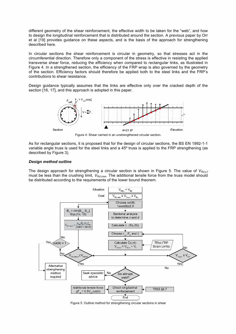
different geometry of the shear reinforcement, the effective width to be taken for the “web”, and how to design the longitudinal reinforcement that is distributed around the section. A previous paper by Orr et al [19] provides guidance on these aspects, and is the basis of the approach for strengthening described here. In circular sections the shear reinforcement is circular in geometry, so that stresses act in the circumferential direction. Therefore only a component of the stress is effective in resisting the applied transverse shear force, reducing the efficiency when compared to rectangular links, as illustrated in Figure 4. In a strengthened section, the efficiency of the FRP wrap is also governed by the geometry of the section. Efficiency factors should therefore be applied both to the steel links and the FRP’s contributions to shear resistance. Design guidance typically assumes that the links are effective only over the cracked depth of the section [16, 17], and this approach is adopted in this paper.
Figure 4: Shear carried in an unstrengthened circular section.
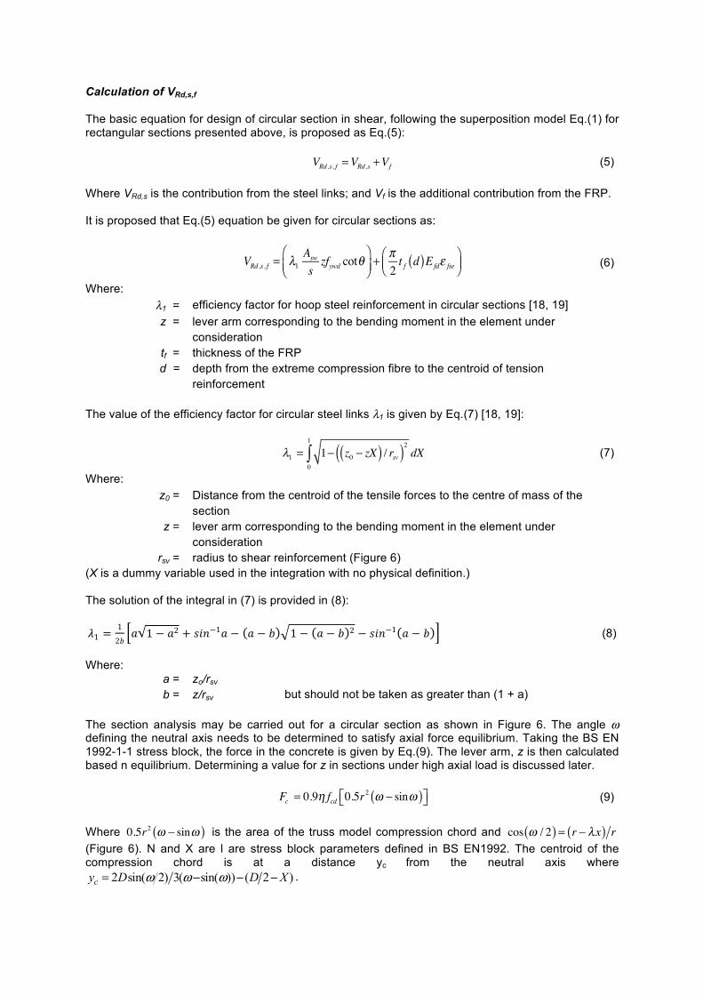
As for rectangular sections, it is proposed that for the design of circular sections, the BS EN 1992-1-1 variable angle truss is used for the steel links and a 45º truss is applied to the FRP strengthening (as described by Figure 3). Design method outline The design approach for strengthening a circular section is shown in Figure 5. The value of VRd,s,f must be less than the crushing limit, VRd,max. The additional tensile force from the truss model should be distributed according to the requirements of the lower bound theorem.
Figure 5. Outline method for strengthening circular sections in shear
Calculation of VRd,s,f The basic equation for design of circular section in shear, following the superposition model Eq.(1) for rectangular sections presented above, is proposed as Eq.(5):
VRd ,s, f =VRd ,s +Vf (5) Where VRd,s is the contribution from the steel links; and Vf is the additional contribution from the FRP. It is proposed that Eq.(5) equation be given for circular sections as:
VRd ,s, f = λ1
Aswszfywd cotθ
⎛⎝⎜
⎞⎠⎟+ π2t f d( )Efdε fse
⎛⎝⎜
⎞⎠⎟ (6)
Where:
The value of the efficiency factor for circular steel links λ1 is given by Eq.(7) [18, 19]:
λ1 = 1− z0 − zX( ) / rsv( )2 dX
0
1
∫ (7)
Where:
(X is a dummy variable used in the integration with no physical definition.) The solution of the integral in (7) is provided in (8):
𝜆1 =
1
2𝑏𝑎 1 − 𝑎2 + 𝑠𝑖𝑛−1𝑎 − 𝑎 − 𝑏 1 − 𝑎 − 𝑏 2 − 𝑠𝑖𝑛−1 𝑎 − 𝑏 (8)
Where:
a = zo/rsv b = z/rsv but should not be taken as greater than (1 + a)
The section analysis may be carried out for a circular section as shown in Figure 6. The angle ω defining the neutral axis needs to be determined to satisfy axial force equilibrium. Taking the BS EN 1992-1-1 stress block, the force in the concrete is given by Eq.(9). The lever arm, z is then calculated based n equilibrium. Determining a value for z in sections under high axial load is discussed later. Fc = 0.9η fcd 0.5r
2 ω − sinω( )⎡⎣ ⎤⎦ (9) Where 0.5r2 ω − sinω( ) is the area of the truss model compression chord and cos ω / 2( ) = r − λx( ) r (Figure 6). N and X are l are stress block parameters defined in BS EN1992. The centroid of the compression chord is at a distance yc from the neutral axis where
)2())sin((3)2sin(2 XDDyc −−−= ωωω .
λ1 = efficiency factor for hoop steel reinforcement in circular sections [18, 19] z = lever arm corresponding to the bending moment in the element under
consideration
tf = thickness of the FRP d = depth from the extreme compression fibre to the centroid of tension
reinforcement
z0 = Distance from the centroid of the tensile forces to the centre of mass of the section
z = lever arm corresponding to the bending moment in the element under consideration
rsv = radius to shear reinforcement (Figure 6)
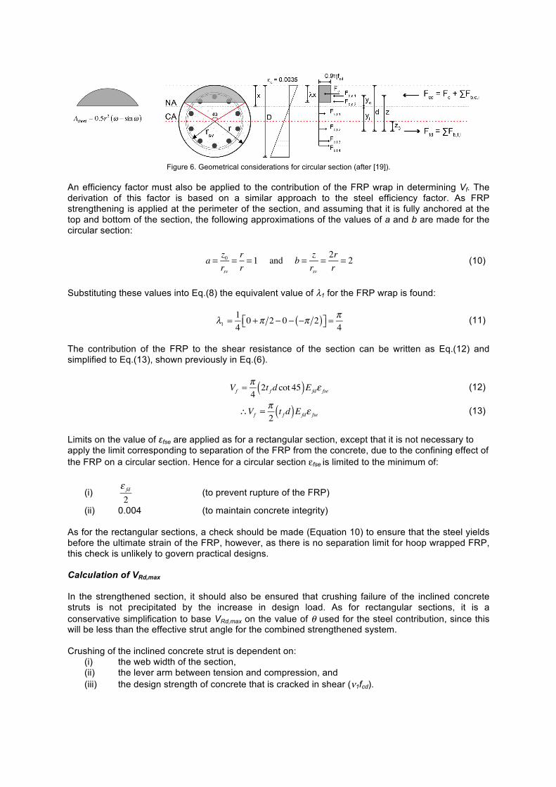
Figure 6. Geometrical considerations for circular section (after [19]).
An efficiency factor must also be applied to the contribution of the FRP wrap in determining Vf. The derivation of this factor is based on a similar approach to the steel efficiency factor. As FRP strengthening is applied at the perimeter of the section, and assuming that it is fully anchored at the top and bottom of the section, the following approximations of the values of a and b are made for the circular section:
a = z0
rsv= rr= 1 and b = z
rsv= 2rr= 2 (10)
Substituting these values into Eq.(8) the equivalent value of λ1 for the FRP wrap is found:
λ1 =
140 +π 2 − 0 − −π 2( )⎡⎣ ⎤⎦ =
π4
(11)
The contribution of the FRP to the shear resistance of the section can be written as Eq.(12) and simplified to Eq.(13), shown previously in Eq.(6).
Vf =
π42t f d cot 45( )Efdε fse (12)
∴Vf =
π2t f d( )Efdε fse (13)
Limits on the value of εfse are applied as for a rectangular section, except that it is not necessary to apply the limit corresponding to separation of the FRP from the concrete, due to the confining effect of the FRP on a circular section. Hence for a circular section εfse is limited to the minimum of:
(i) ε fd
2 (to prevent rupture of the FRP)
(ii) 0.004 (to maintain concrete integrity) As for the rectangular sections, a check should be made (Equation 10) to ensure that the steel yields before the ultimate strain of the FRP, however, as there is no separation limit for hoop wrapped FRP, this check is unlikely to govern practical designs. Calculation of VRd,max In the strengthened section, it should also be ensured that crushing failure of the inclined concrete struts is not precipitated by the increase in design load. As for rectangular sections, it is a conservative simplification to base VRd,max on the value of θ used for the steel contribution, since this will be less than the effective strut angle for the combined strengthened system. Crushing of the inclined concrete strut is dependent on:
(i) the web width of the section, (ii) the lever arm between tension and compression, and (iii) the design strength of concrete that is cracked in shear (ν1fcd).
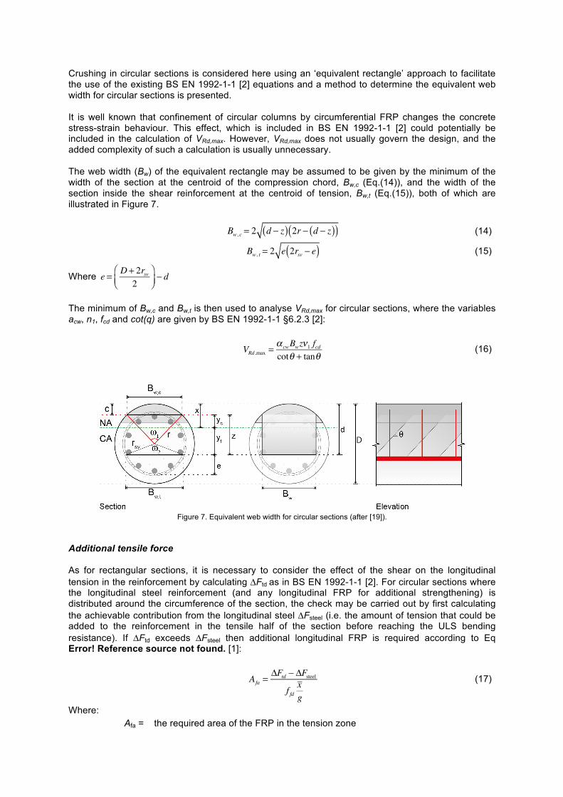
Crushing in circular sections is considered here using an ‘equivalent rectangle’ approach to facilitate the use of the existing BS EN 1992-1-1 [2] equations and a method to determine the equivalent web width for circular sections is presented. It is well known that confinement of circular columns by circumferential FRP changes the concrete stress-strain behaviour. This effect, which is included in BS EN 1992-1-1 [2] could potentially be included in the calculation of VRd,max. However, VRd,max does not usually govern the design, and the added complexity of such a calculation is usually unnecessary. The web width (Bw) of the equivalent rectangle may be assumed to be given by the minimum of the width of the section at the centroid of the compression chord, Bw,c (Eq.(14)), and the width of the section inside the shear reinforcement at the centroid of tension, Bw,t (Eq.(15)), both of which are illustrated in Figure 7.
Bw, c = 2 d − z( ) 2r − d − z( )( ) (14)
Bw, t = 2 e 2rsv − e( ) (15)
Where e = D + 2rsv2
⎛⎝⎜
⎞⎠⎟− d
The minimum of Bw,c and Bw,t is then used to analyse VRd,max for circular sections, where the variables acw, n1, fcd and cot(q) are given by BS EN 1992-1-1 §6.2.3 [2]:
VRd ,max =
α cwBwzν1 fcdcotθ + tanθ
(16)
Figure 7. Equivalent web width for circular sections (after [19]).
Additional tensile force As for rectangular sections, it is necessary to consider the effect of the shear on the longitudinal tension in the reinforcement by calculating ΔFtd as in BS EN 1992-1-1 [2]. For circular sections where the longitudinal steel reinforcement (and any longitudinal FRP for additional strengthening) is distributed around the circumference of the section, the check may be carried out by first calculating the achievable contribution from the longitudinal steel ΔFsteel (i.e. the amount of tension that could be added to the reinforcement in the tensile half of the section before reaching the ULS bending resistance). If ΔFtd exceeds ΔFsteel then additional longitudinal FRP is required according to Eq Error! Reference source not found. [1]:
Afa =ΔFtd − ΔFsteel
f fdxg
(17)
Where: Afa = the required area of the FRP in the tension zone
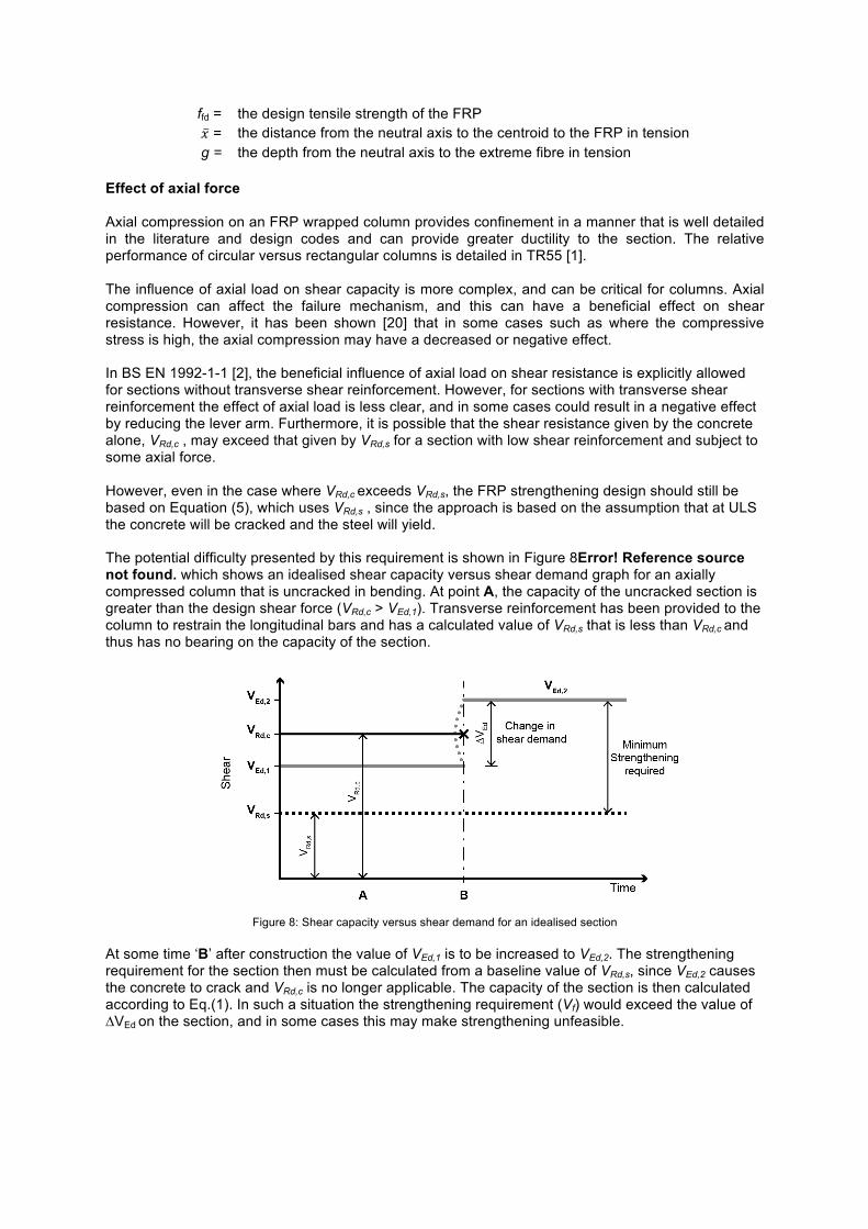
Effect of axial force Axial compression on an FRP wrapped column provides confinement in a manner that is well detailed in the literature and design codes and can provide greater ductility to the section. The relative performance of circular versus rectangular columns is detailed in TR55 [1]. The influence of axial load on shear capacity is more complex, and can be critical for columns. Axial compression can affect the failure mechanism, and this can have a beneficial effect on shear resistance. However, it has been shown [20] that in some cases such as where the compressive stress is high, the axial compression may have a decreased or negative effect. In BS EN 1992-1-1 [2], the beneficial influence of axial load on shear resistance is explicitly allowed for sections without transverse shear reinforcement. However, for sections with transverse shear reinforcement the effect of axial load is less clear, and in some cases could result in a negative effect by reducing the lever arm. Furthermore, it is possible that the shear resistance given by the concrete alone, VRd,c , may exceed that given by VRd,s for a section with low shear reinforcement and subject to some axial force. However, even in the case where VRd,c exceeds VRd,s, the FRP strengthening design should still be based on Equation (5), which uses VRd,s , since the approach is based on the assumption that at ULS the concrete will be cracked and the steel will yield. The potential difficulty presented by this requirement is shown in Figure 8Error! Reference source not found. which shows an idealised shear capacity versus shear demand graph for an axially compressed column that is uncracked in bending. At point A, the capacity of the uncracked section is greater than the design shear force (VRd,c > VEd,1). Transverse reinforcement has been provided to the column to restrain the longitudinal bars and has a calculated value of VRd,s that is less than VRd,c and thus has no bearing on the capacity of the section.
Figure 8: Shear capacity versus shear demand for an idealised section
At some time ‘B’ after construction the value of VEd,1 is to be increased to VEd,2. The strengthening requirement for the section then must be calculated from a baseline value of VRd,s, since VEd,2 causes the concrete to crack and VRd,c is no longer applicable. The capacity of the section is then calculated according to Eq.(1). In such a situation the strengthening requirement (Vf) would exceed the value of ∆VEd on the section, and in some cases this may make strengthening unfeasible.
ffd = the design tensile strength of the FRP 𝑥 = the distance from the neutral axis to the centroid to the FRP in tension g = the depth from the neutral axis to the extreme fibre in tension
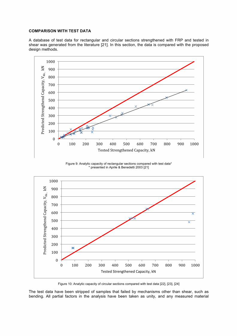
COMPARISON WITH TEST DATA A database of test data for rectangular and circular sections strengthened with FRP and tested in shear was generated from the literature [21]. In this section, the data is compared with the proposed design methods.
Figure 9: Analytic capacity of rectangular sections compared with test data* * presented in Aprile & Benedetti 2003 [21]
Figure 10: Analytic capacity of circular sections compared with test data [22], [23], [24]
The test data have been stripped of samples that failed by mechanisms other than shear, such as bending. All partial factors in the analysis have been taken as unity, and any measured material
0
100
200
300
400
500
600
700
800
900
1000
0 100 200 300 400 500 600 700 800 900 1000
Predicted Strengthend Capacity, V
Rk , kN
Tested Strengthened Capacity, kN
0
100
200
300
400
500
600
700
800
900
1000
0 100 200 300 400 500 600 700 800 900 1000
Predicted Strengthend Capacity, V
Rk , kN
Tested Strengthened Capacity, kN
property values stated in the source papers have been taken to represent characteristic values for the purposes of calculating the shear capacities. The test data for rectangular section shows a good agreement with the proposed method. The predicted capacities are slightly, but not unduly, conservative in most cases and achieve a good fit to the tested capacities. There are limited data for static load tests of strengthened circular columns strengthened in shear. Strengthening of circular columns for earthquake actions has become common in earthquake prone regions, and much of the literature focus on this application, rather than static loading. Consequently, all the test data available are from test regimes designed to study the effect cyclic loading, which are then tested to destruction. More research is needed in this area to verify the results for circular columns under non-cyclic actions such as vehicle impact. Testing has been undertaken to verify the results of the proposed method for unstrengthened sections [19] and combined with the results for rectangular sections confidence in the proposed method for circular sections can be derived. CONCLUSIONS This paper presents methods for designing shear strengthening of concrete members using FRP. The background to the development of the design rules that were included in TR55 third edition has been described. Further detail has been provided relating to the design of strengthening for circular sections. Test data is required to fully verify the approach for shear resistance of strengthened circular sections for impact loading.
REFERENCES
1. Concrete Society, Design Guidance for Strengthening Concrete Structures Using Fibre Composite Materials, TR55, 3rd Edition, Camberley: Concrete Society (2012)
2. BS EN 1992-1-1, Eurocode 2: Design of concrete structures - Part 1-1: General rules and rules for buildings, BSI: London, UK, 2004
3. BS 8110-1, Structural use of concrete - Part 1: Code of practice for design and construction, BSI: London, UK, 1997
4. BS5400-4, Steel, concrete and composite bridges. Code of practice for design of concrete bridges., BSI: London, UK, 1990
5. Perera, K., et al. Bond mechanisms of various shapes of NSM CFRP bars. in Advanced Composites in Construction (ACIC 2009). Edinburgh, 1-3 September 2009, 2009 of Conference.
6. Valerio, P., T. Ibell, and A.P. Darby, Deep embedment of FRP for the shear strengthening of concrete. Proceedings of the ICE - Structures and Buildings, 162(5): p. 311-321 (2009)
7. BS EN 1990:2002+A1, Eurocode - Basis of structural design, BSI: London, UK, 2005 8. BS EN 1991, Eurocode 1: Actions on structures, BSI: London, UK, 2009 9. Mörsch, E., Der Eisenbeton, seine Theorie und Anwendung (Reinforced Concrete, theory and
practical application. , Stuttgart: Wittwer, (1908) 10. Ritter, W., Die bauweise hennebique (Construction techniques of Hennebique). Zurich:
Schweizerische Bazeitung, (1899) 11. Withey, M.O., Tests of plain and reinforced concrete series of 1906. Engineering Series. Vol.
4, Wisconsin: University of Wisconsin (1907) 12. ACI 318, Building Code Requirements for Structural Concrete and Commentary, ACI: 2005 13. ACI 440, Fiber Reinforced Polymer Reinforcement: Guide for the Design and Construction of
Structural Concrete Reinforced with FRP Bars, ACI: 2006 14. BS EN 1992-2, Eurocode 2. Design of Concrete Structures. Part 2: Concrete bridges - Design
and detailing rules, BSI: London, UK, 2005 15. Neubauer, U. and F. Rostasy. Design aspects of concrete structures strengthened with
externally bonded CFRP plates, Concrete and Composites. in Proceedings of the 7th International Conference on Structural Faults and Repair. Edinburgh, 1997 of Conference.
16. Kowalsky, M.J. and M.J.N. Priestley, Improved analytical model for shear strength of circular reinforced concrete columns in seismic regions. ACI Struct J, 97(42): p. 388-296 (2000)
17. Feltham, I., Shear in reinforced concrete piles and circular columns. The Structural Engineer, 84(11): p. 27-31 (2004)
18. Turmo, T., G. Ramos, and A.C. Aparicio, Shear truss analogy for concrete members of solid and hollow circular cross section. Engineering Structures, 31(2): p. 455-465 (2009)
19. Orr, J.J., et al., Shear design of circular concrete sections using the Eurocode 2 truss model. The Structural Engineer, 88(23/24): p. 26-32 (2010)
20. Gupta, R.P. and M.P. Collins, Evaluation of Shear Design Procedures for Reinforced Concrete Members under Axial Compression. ACI Struct J, 98(4): p. 537-547 (2001)
21 Aprile, A. and A. Benedetti, Coupled flexural-shear design of R/C beams strengthened with FRP. Composites: Part B 35, (2004) (paper summarises a series of data. Individual papers are referenced further in the main source)
22 Saadatmanesh, H., M.R. Ehsani, and L. Jin, Seismic Strengthening of Circular Bridge Pier Models with Fiber Composites. ACI Struct J., 93(6): p. 639-647. (1996)
23 Xiao, Y., H. Wu, and G. Martin, Prefabricated Composite Jacketing of RC Columns for Enhanced Shear Strength. ASCE J. Struct. Eng., 125(3), p. 255–264 (1999)
24 Li Y.-F., Y.-Y. Sung, A Study on the Shear-failure of Circular Sectioned Bridge Column Retrofitted by Using CFRP Jacketing. Journal of Reinforced Plastics and Composites, 23(8), p. 811-830 (2004)