Embed Size (px)
Citation preview
1 N E W S
Achieving Transmission Based Train Control in London – 1995 Tube Stock System Compatibility
by P. Balant Alcatel Canada, M. Borup ALSTOM Transport and A. Ogunsola Parsons Group International & Tube Lines Ltd
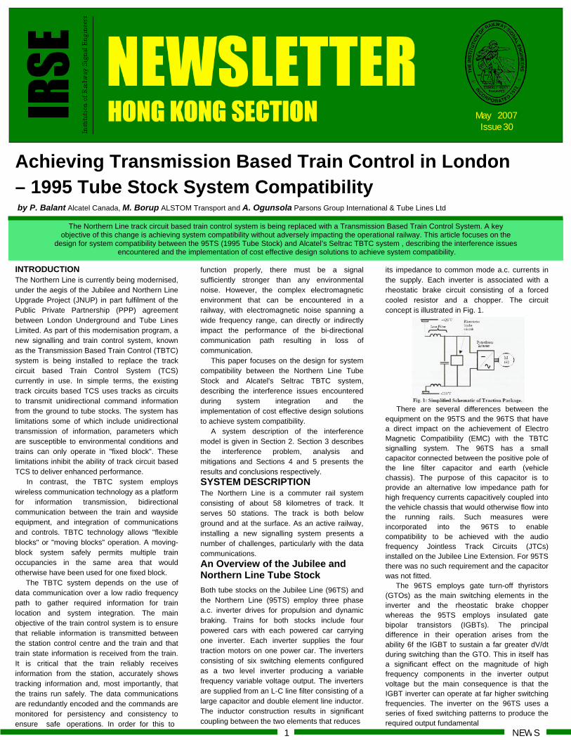
The Northern Line track circuit based train control system is being replaced with a Transmission Based Train Control System. A key objective of this change is achieving system compatibility without adversely impacting the operational railway. This article focuses on the
design for system compatibility between the 95TS (1995 Tube Stock) and Alcatel’s Seltrac TBTC system , describing the interference issues encountered and the implementation of cost effective design solutions to achieve system compatibility.
its impedance to common mode a.c. currents in the supply. Each inverter is associated with a rheostatic brake circuit consisting of a forced cooled resistor and a chopper. The circuit concept is illustrated in Fig. 1.
There are several differences between the
equipment on the 95TS and the 96TS that have a direct impact on the achievement of Electro Magnetic Compatibility (EMC) with the TBTC signalling system. The 96TS has a small capacitor connected between the positive pole of the line filter capacitor and earth (vehicle chassis). The purpose of this capacitor is to provide an alternative low impedance path for high frequency currents capacitively coupled into the vehicle chassis that would otherwise flow into the running rails. Such measures were incorporated into the 96TS to enable compatibility to be achieved with the audio frequency Jointless Track Circuits (JTCs) installed on the Jubilee Line Extension. For 95TS there was no such requirement and the capacitor was not fitted.
The 96TS employs gate turn-off thyristors (GTOs) as the main switching elements in the inverter and the rheostatic brake chopper whereas the 95TS employs insulated gate bipolar transistors (IGBTs). The principal difference in their operation arises from the ability 6f the IGBT to sustain a far greater dV/dt during switching than the GTO. This in itself has a significant effect on the magnitude of high frequency components in the inverter output voltage but the main consequence is that the IGBT inverter can operate at far higher switching frequencies. The inverter on the 96TS uses a series of fixed switching patterns to produce the required output fundamental
function properly, there must be a signal sufficiently stronger than any environmental noise. However, the complex electromagnetic environment that can be encountered in a railway, with electromagnetic noise spanning a wide frequency range, can directly or indirectly impact the performance of the bi-directional communication path resulting in loss of communication.
This paper focuses on the design for system compatibility between the Northern Line Tube Stock and Alcatel's Seltrac TBTC system, describing the interference issues encountered during system integration and the implementation of cost effective design solutions to achieve system compatibility.
A system description of the interference model is given in Section 2. Section 3 describes the interference problem, analysis and mitigations and Sections 4 and 5 presents the results and conclusions respectively. SYSTEM DESCRIPTION The Northern Line is a commuter rail system consisting of about 58 kilometres of track. It serves 50 stations. The track is both below ground and at the surface. As an active railway, installing a new signalling system presents a number of challenges, particularly with the data communications. An Overview of the Jubilee and Northern Line Tube Stock Both tube stocks on the Jubilee Line (96TS) and the Northern Line (95TS) employ three phase a.c. inverter drives for propulsion and dynamic braking. Trains for both stocks include four powered cars with each powered car carrying one inverter. Each inverter supplies the four traction motors on one power car. The inverters consisting of six switching elements configured as a two level inverter producing a variable frequency variable voltage output. The inverters are supplied from an L-C line filter consisting of a large capacitor and double element line inductor. The inductor construction results in significant coupling between the two elements that reduces
INTRODUCTION The Northern Line is currently being modernised, under the aegis of the Jubilee and Northern Line Upgrade Project (JNUP) in part fulfilment of the Public Private Partnership (PPP) agreement between London Underground and Tube Lines Limited. As part of this modernisation program, a new signalling and train control system, known as the Transmission Based Train Control (TBTC) system is being installed to replace the track circuit based Train Control System (TCS) currently in use. In simple terms, the existing track circuits based TCS uses tracks as circuits to transmit unidirectional command information from the ground to tube stocks. The system has limitations some of which include unidirectional transmission of information, parameters which are susceptible to environmental conditions and trains can only operate in "fixed block". These limitations inhibit the ability of track circuit based TCS to deliver enhanced performance.
In contrast, the TBTC system employs wireless communication technology as a platform for information transmission, bidirectional communication between the train and wayside equipment, and integration of communications and controls. TBTC technology allows "flexible blocks" or "moving blocks" operation. A moving-block system safely permits multiple train occupancies in the same area that would otherwise have been used for one fixed block.
The TBTC system depends on the use of data communication over a low radio frequency path to gather required information for train location and system integration. The main objective of the train control system is to ensure that reliable information is transmitted between the station control centre and the train and that train state information is received from the train. It is critical that the train reliably receives information from the station, accurately shows tracking information and, most importantly, that the trains run safely. The data communications are redundantly encoded and the commands are monitored for persistency and consistency to ensure safe operations. In order for this to
May 2007 Issue 30
IRSE
Agenda N E W S
voltage and current. The switching frequency using this approach is not fixed and varies with operating point. The maximum switching frequency is limited to approximately 400 Hz. The rheostatic chopper on 96TS is operated at a fixed frequency of 300 Hz. In comparison, the inverter on the 95TS uses a conventional Pulse Width Modulation strategy. The carrier frequency is fixed at 2400 Hz and the rheostatic brake chopper also operates at a fixed frequency of 2400 Hz. The combination of higher switching frequencies, higher dV/dt and lack of suppression of capacitively coupled currents results in the 95TS producing significantly higher interference currents at the frequencies of interest. TBTC System Description The primary design goal of traditional railway signalling systems is to maintain positive train separation through wayside signals, train stops and vigilant drivers; no train is to enter a block occupied by another train. In contrast, the primary design goal of a moving-block system is to provide a safe operation with greater capacity (throughput and inter-station run times), allowing reduced train separation distance through improved position resolution and movement authority updating rate. Inherent with a TBTC moving-block system is the rapid and continuous data communication between the train and the wayside equipment. Wayside signals are not used.
The safe separation between trains is dynamically calculated based on the maximum operating speeds, braking curves and locations of the trains on the guideway. Because of the high resolution of position reporting (nominally 6.25 metres), a following train may safely close up to within safe braking distance from the last verified position of the rear of a preceding train, based on the maximum allowed speed in that section of the guideway. A significant reduction in headway relative to fixed-block systems is possible since a Controlled Train need not be stopped outside the "block" occupied by a preceding train.
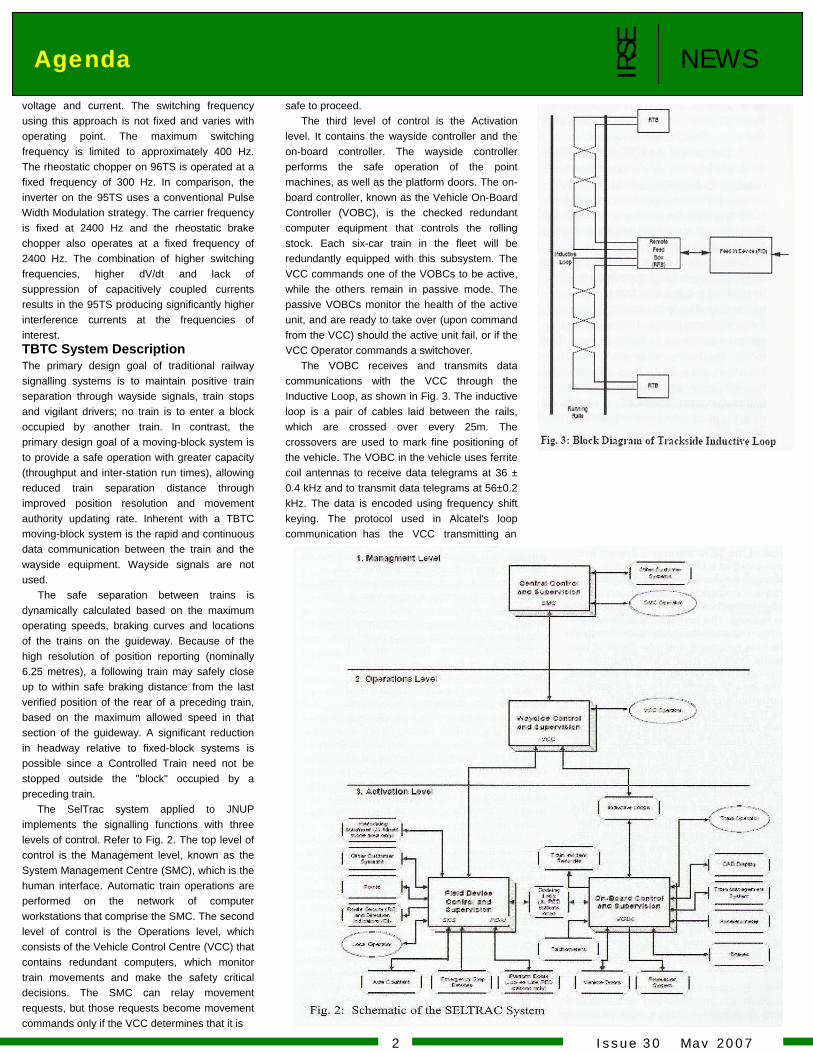
safe to proceed. The third level of control is the Activation
level. It contains the wayside controller and the on-board controller. The wayside controller performs the safe operation of the point machines, as well as the platform doors. The on-board controller, known as the Vehicle On-Board Controller (VOBC), is the checked redundant computer equipment that controls the rolling stock. Each six-car train in the fleet will be redundantly equipped with this subsystem. The VCC commands one of the VOBCs to be active, while the others remain in passive mode. The passive VOBCs monitor the health of the active unit, and are ready to take over (upon command from the VCC) should the active unit fail, or if the VCC Operator commands a switchover.
The VOBC receives and transmits data communications with the VCC through the Inductive Loop, as shown in Fig. 3. The inductive loop is a pair of cables laid between the rails, which are crossed over every 25m. The crossovers are used to mark fine positioning of the vehicle. The VOBC in the vehicle uses ferrite coil antennas to receive data telegrams at 36 ± 0.4 kHz and to transmit data telegrams at 56±0.2 kHz. The data is encoded using frequency shift keying. The protocol used in Alcatel's loop communication has the VCC transmitting an
The SelTrac system applied to JNUP implements the signalling functions with three levels of control. Refer to Fig. 2. The top level of control is the Management level, known as the System Management Centre (SMC), which is the human interface. Automatic train operations are performed on the network of computer workstations that comprise the SMC. The second level of control is the Operations level, which consists of the Vehicle Control Centre (VCC) that contains redundant computers, which monitor train movements and make the safety critical decisions. The SMC can relay movement requests, but those requests become movement commands only if the VCC determines that it is
2 I s s u e 3 0 M a y 2 0 0 7
IRSE
N E W S Advertisement
3 I s s u e 3 0 M a y 2 0 0 7
IRSE
Agenda N E W S
4 I s s u e 3 0 M a y 2 0 0 7
component in the running rails. In a four rail system, such currents are a typical result of capacitive coupling between an inverter output and the vehicle chassis. Such currents must ultimately flow back to the input filter capacitor for the inverter. There is no obvious path for these currents on the 95TS trains and the majority of the current will flow via the running rails, substation and the supply rails. Previous work on 96TS showed that the relevant stray capacitance was concentrated in the traction motor and the traction inverter itself. Even though the construction of the inverter is different between the two stocks, considerable stray capacitance exists between the live base of the power devices and the earthed heatsink on which they are mounted. The traction motors on 95TS and 96TS are very similar and the stray capacitance model developed for 96TS is also valid for the 95TS. The fitting of a temporary modification to control these currents enabled further investigations to take place.
Relatively high levels of interference currents were observed in dynamic braking. Investigations confirmed that this was caused by the flux emanating from the brake resistor being coupled directly into the TBTC Inductive Loop. The inductance of the brake resistor is designed to be low and this gives rise to very high levels of harmonic currents in the brake resistor when operating in a chopper circuit. Previous work on leakage flux from a similar brake resistor indicated that low levels of leakage flux would exist at the frequencies of interest and calculations indicated that even very loose coupling to the TBTC Inductive Loop would cause significant degradation in signal to noise ratio.
Again, temporary modifications to suppress this source of interference allowed investigations of yet lower levels of interference current.
The third interference mechanism that was identified was direct coupling between the traction motor leads and the TBTC Inductive Loop. The particular area of interest was the drop leads to the bogie. The concern here is that the capacitively coupled currents in the traction motor appear effectively as common mode current in the bogie drop leads. These currents will therefore generate a significant external field. The position of the drop leads on the two bogies supplied by the traction inverter and the geometry of the drop lead arrangement results in a significant coupling into the TBTC Inductive Loop.
Compatibility Investigations and Analysis Given the advanced state of the programme, rapid resolution of the problem was required. A multidisciplinary working group was therefore established with the specific purpose of determining through test and theoretical analysis the different interference mechanisms and validating possible methods of improving the signal to noise ratio on the TBTC train/track communication links. This group consisted of design and test engineers specialising in signalling, EMC, traction systems and systems assurance.
The approach to the investigation was essentially iterative involving analysis, modelling, trial solution design and validation. Considerable effort was spent developing various models in an attempt to predict the interference levels and the effect of proposed solutions. Models were developed for the running and supply rail system in conjunction with elements of the vehicle structure, the traction inverter in terms of its high frequency output spectrum, high frequency characteristics of key components such as traction motors and simplified multi-train models for investigation of inter train effects.
The principal difficulty in analysing and modelling this type of interference mechanism, especially at the frequencies of concern, lies in the physical complexity of the system. A combination of distributed and lumped resistance capacitance and inductance within a complex mechanical arrangement makes accurate prediction of interference currents very difficult with practicable models. Nevertheless, modelling was highly beneficial in developing an understanding of the interference mechanisms and the likely effectiveness of proposed solutions.
Investigatory testing took place at Tube Lines Highgate Test Facility (HTF). Current measurements were made using Rogowski coils placed around the running and supply rails and around various conductors within the train borne power circuits. A maximum of four Rogowski coils could be accommodated simultaneously by the recording instrumentation.
The sensitivity of the TBTC system to interference was originally characterised by limits for in-band currents in the supply rails. Initial investigatory testing revealed that significant interference currents also flowed in the running rails. Simultaneous measurements of the currents in the running and supply rails indicated a large common mode component in the supply rails approximately equalled by a common mode
83-bit telegram to the VaBC at 1200 baud; the VOBC responds with a 43-bit telegram at 600 baud. The checked redundant microprocessors of the VOBC test incoming telegrams from the VCC for errors by way of redundancy, persistency, and plausibility checks. When these tests are passed, the VOBC interprets the command message. The VOBC will act only on telegrams that are explicitly addressed to it.
Safety analysis of the Inductive Loop data communications has determined a lower bound for the signal level that can be tolerated relative to the amount of noise in these frequency bands. This results in a system requirement for Signal to Noise Ratio (SNR). The design goal for the SNR on the Inductive Loop is 20 decibels (dB); however, the SNR safety requirement is 10 dB or better. Concerns for reliability of service will raise the practical minimum level to about 15 dB.
SYSTEM COMPATIBILITY Site Trials Early testing of the signalling equipment in a railway environment is a central part of the project. For this purpose, an integrated test track (known as Highgate Test Facility, HTF) was created at Highgate Depot. Virtually, all aspects of the TBTC signalling system are implemented at HTF. The test facility provides an environment where signalling and system compatibility issues can be investigated without impacting the operation of the railway. The test facility is also used to perform system checks and demonstrate the various functions and interfaces of the signalling system. JNUP's EMC management program also requires early site trials, with the view of identifying and mitigating any potential signalling compatibility issues, during the early stages of the project.
Early functional TBTC system test with the 95TS resulted in negative SNR. It was observed that the 95TS produced significant wide band harmonics, including at 36 kHz and 56 kHz, during motoring and braking. The amplitude of noise produced by the 95TS was significant enough to impact the ability of the TBTC system communication link between wayside equipment and train. The objective was to achieve a SNR of 25 dB or better. The worst case SNR measured was -16 dB, thus the EMC design objective was seeking a 41 dB improvement in uplink (at 36 kHz) and a 15 dB improvement in the downlink (at 56 kHz). In addition, it was important to ensure that EMC design changes implemented do not adversely change the electromagnetic characteristic of the infrastructure.
IRSE
Agenda N E W S
5 I s s u e 3 0 M a y 2 0 0 7
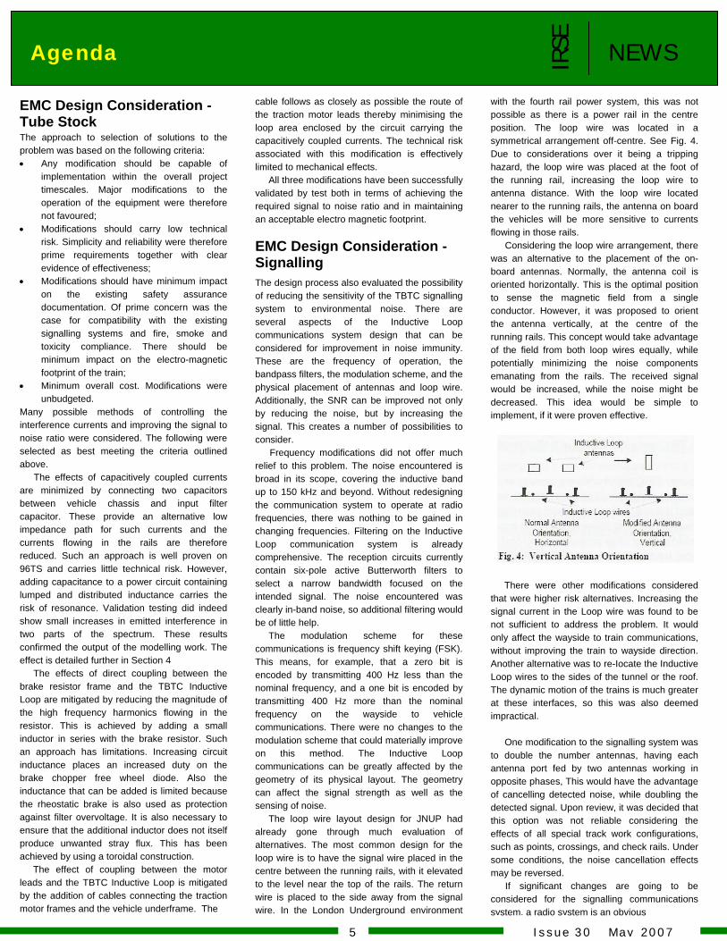
with the fourth rail power system, this was not possible as there is a power rail in the centre position. The loop wire was located in a symmetrical arrangement off-centre. See Fig. 4. Due to considerations over it being a tripping hazard, the loop wire was placed at the foot of the running rail, increasing the loop wire to antenna distance. With the loop wire located nearer to the running rails, the antenna on board the vehicles will be more sensitive to currents flowing in those rails.
Considering the loop wire arrangement, there was an alternative to the placement of the on-board antennas. Normally, the antenna coil is oriented horizontally. This is the optimal position to sense the magnetic field from a single conductor. However, it was proposed to orient the antenna vertically, at the centre of the running rails. This concept would take advantage of the field from both loop wires equally, while potentially minimizing the noise components emanating from the rails. The received signal would be increased, while the noise might be decreased. This idea would be simple to implement, if it were proven effective.
There were other modifications considered
that were higher risk alternatives. Increasing the signal current in the Loop wire was found to be not sufficient to address the problem. It would only affect the wayside to train communications, without improving the train to wayside direction. Another alternative was to re-Iocate the Inductive Loop wires to the sides of the tunnel or the roof. The dynamic motion of the trains is much greater at these interfaces, so this was also deemed impractical.
One modification to the signalling system was
to double the number antennas, having each antenna port fed by two antennas working in opposite phases, This would have the advantage of cancelling detected noise, while doubling the detected signal. Upon review, it was decided that this option was not reliable considering the effects of all special track work configurations, such as points, crossings, and check rails. Under some conditions, the noise cancellation effects may be reversed.
If significant changes are going to be considered for the signalling communications system, a radio system is an obvious
cable follows as closely as possible the route of the traction motor leads thereby minimising the loop area enclosed by the circuit carrying the capacitively coupled currents. The technical risk associated with this modification is effectively limited to mechanical effects.
All three modifications have been successfully validated by test both in terms of achieving the required signal to noise ratio and in maintaining an acceptable electro magnetic footprint.
EMC Design Consideration -Signalling The design process also evaluated the possibility of reducing the sensitivity of the TBTC signalling system to environmental noise. There are several aspects of the Inductive Loop communications system design that can be considered for improvement in noise immunity. These are the frequency of operation, the bandpass filters, the modulation scheme, and the physical placement of antennas and loop wire. Additionally, the SNR can be improved not only by reducing the noise, but by increasing the signal. This creates a number of possibilities to consider.
Frequency modifications did not offer much relief to this problem. The noise encountered is broad in its scope, covering the inductive band up to 150 kHz and beyond. Without redesigning the communication system to operate at radio frequencies, there was nothing to be gained in changing frequencies. Filtering on the Inductive Loop communication system is already comprehensive. The reception circuits currently contain six-pole active Butterworth filters to select a narrow bandwidth focused on the intended signal. The noise encountered was clearly in-band noise, so additional filtering would be of little help.
The modulation scheme for these communications is frequency shift keying (FSK). This means, for example, that a zero bit is encoded by transmitting 400 Hz less than the nominal frequency, and a one bit is encoded by transmitting 400 Hz more than the nominal frequency on the wayside to vehicle communications. There were no changes to the modulation scheme that could materially improve on this method. The Inductive Loop communications can be greatly affected by the geometry of its physical layout. The geometry can affect the signal strength as well as the sensing of noise.
The loop wire layout design for JNUP had already gone through much evaluation of alternatives. The most common design for the loop wire is to have the signal wire placed in the centre between the running rails, with it elevated to the level near the top of the rails. The return wire is placed to the side away from the signal wire. In the London Underground environment
EMC Design Consideration -Tube Stock The approach to selection of solutions to the problem was based on the following criteria: • Any modification should be capable of
implementation within the overall project timescales. Major modifications to the operation of the equipment were therefore not favoured;
• Modifications should carry low technical risk. Simplicity and reliability were therefore prime requirements together with clear evidence of effectiveness;
• Modifications should have minimum impact on the existing safety assurance documentation. Of prime concern was the case for compatibility with the existing signalling systems and fire, smoke and toxicity compliance. There should be minimum impact on the electro-magnetic footprint of the train;
• Minimum overall cost. Modifications were unbudgeted.
Many possible methods of controlling the interference currents and improving the signal to noise ratio were considered. The following were selected as best meeting the criteria outlined above.
The effects of capacitively coupled currents are minimized by connecting two capacitors between vehicle chassis and input filter capacitor. These provide an alternative low impedance path for such currents and the currents flowing in the rails are therefore reduced. Such an approach is well proven on 96TS and carries little technical risk. However, adding capacitance to a power circuit containing lumped and distributed inductance carries the risk of resonance. Validation testing did indeed show small increases in emitted interference in two parts of the spectrum. These results confirmed the output of the modelling work. The effect is detailed further in Section 4
The effects of direct coupling between the brake resistor frame and the TBTC Inductive Loop are mitigated by reducing the magnitude of the high frequency harmonics flowing in the resistor. This is achieved by adding a small inductor in series with the brake resistor. Such an approach has limitations. Increasing circuit inductance places an increased duty on the brake chopper free wheel diode. Also the inductance that can be added is limited because the rheostatic brake is also used as protection against filter overvoltage. It is also necessary to ensure that the additional inductor does not itself produce unwanted stray flux. This has been achieved by using a toroidal construction.
The effect of coupling between the motor leads and the TBTC Inductive Loop is mitigated by the addition of cables connecting the traction motor frames and the vehicle underframe. The
IRSE
Agenda N E W S
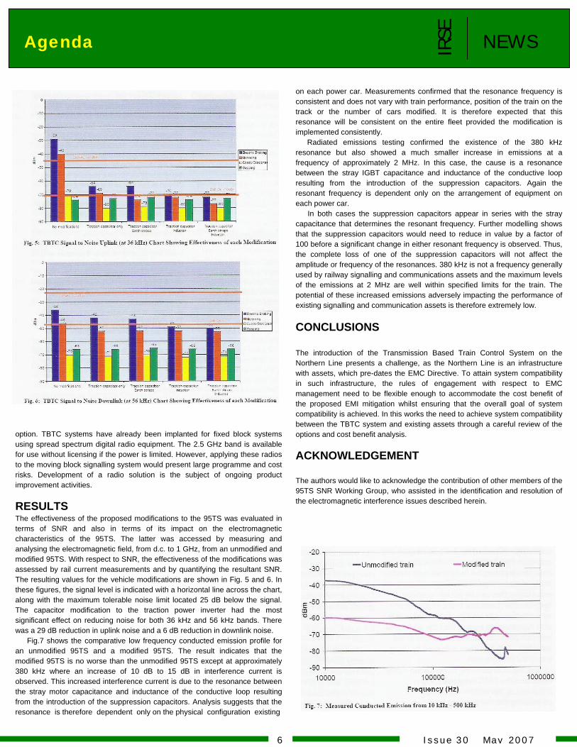
option. TBTC systems have already been implanted for fixed block systems using spread spectrum digital radio equipment. The 2.5 GHz band is available for use without licensing if the power is limited. However, applying these radios to the moving block signalling system would present large programme and cost risks. Development of a radio solution is the subject of ongoing product improvement activities. RESULTS The effectiveness of the proposed modifications to the 95TS was evaluated in terms of SNR and also in terms of its impact on the electromagnetic characteristics of the 95TS. The latter was accessed by measuring and analysing the electromagnetic field, from d.c. to 1 GHz, from an unmodified and modified 95TS. With respect to SNR, the effectiveness of the modifications was assessed by rail current measurements and by quantifying the resultant SNR. The resulting values for the vehicle modifications are shown in Fig. 5 and 6. In these figures, the signal level is indicated with a horizontal line across the chart, along with the maximum tolerable noise limit located 25 dB below the signal. The capacitor modification to the traction power inverter had the most significant effect on reducing noise for both 36 kHz and 56 kHz bands. There was a 29 dB reduction in uplink noise and a 6 dB reduction in downlink noise.
Fig.7 shows the comparative low frequency conducted emission profile for an unmodified 95TS and a modified 95TS. The result indicates that the modified 95TS is no worse than the unmodified 95TS except at approximately 380 kHz where an increase of 10 dB to 15 dB in interference current is observed. This increased interference current is due to the resonance between the stray motor capacitance and inductance of the conductive loop resulting from the introduction of the suppression capacitors. Analysis suggests that the resonance is therefore dependent only on the physical configuration existing
on each power car. Measurements confirmed that the resonance frequency is consistent and does not vary with train performance, position of the train on the track or the number of cars modified. It is therefore expected that this resonance will be consistent on the entire fleet provided the modification is implemented consistently.
Radiated emissions testing confirmed the existence of the 380 kHz resonance but also showed a much smaller increase in emissions at a frequency of approximately 2 MHz. In this case, the cause is a resonance between the stray IGBT capacitance and inductance of the conductive loop resulting from the introduction of the suppression capacitors. Again the resonant frequency is dependent only on the arrangement of equipment on each power car.
In both cases the suppression capacitors appear in series with the stray capacitance that determines the resonant frequency. Further modelling shows that the suppression capacitors would need to reduce in value by a factor of 100 before a significant change in either resonant frequency is observed. Thus, the complete loss of one of the suppression capacitors will not affect the amplitude or frequency of the resonances. 380 kHz is not a frequency generally used by railway signalling and communications assets and the maximum levels of the emissions at 2 MHz are well within specified limits for the train. The potential of these increased emissions adversely impacting the performance of existing signalling and communication assets is therefore extremely low.
CONCLUSIONS The introduction of the Transmission Based Train Control System on the Northern Line presents a challenge, as the Northern Line is an infrastructure with assets, which pre-dates the EMC Directive. To attain system compatibility in such infrastructure, the rules of engagement with respect to EMC management need to be flexible enough to accommodate the cost benefit of the proposed EMI mitigation whilst ensuring that the overall goal of system compatibility is achieved. In this works the need to achieve system compatibility between the TBTC system and existing assets through a careful review of the options and cost benefit analysis. ACKNOWLEDGEMENT The authors would like to acknowledge the contribution of other members of the 95TS SNR Working Group, who assisted in the identification and resolution of the electromagnetic interference issues described herein.
6 I s s u e 3 0 M a y 2 0 0 7
IRSE
N E W S Advertisement
7
I s s u e 3 0 M a y 2 0 0 7
I s s u e 3 0 M a y 2 0 0 7 8
N E W SIRSE
Agenda
I s s u e 3 0 M a y 2 0 0 7 9
N E W SIRSE
Agenda
I s s u e 3 0 M a y 2 0 0 7 10
N E W SIRSE
Agenda
IRSE
Advertisement N E W S
11 I s s u e 3 0 M a y 2 0 0 7
I s s u e 3 0 M a y 2 0 0 7 12
N E W SIRSE
Agenda
I s s u e 3 0 M a y 2 0 0 7 13
N E W SIRSE
Agenda

進一步連繫 多一分親近
進一步連繫 多一分親近 One Link Further One Step Closer
14 I s s u e 3 0 M a y 2 0 0 7
N E W SIRSE
Advertisement
9 May 2007 Lantau Airport Railway Wind Monitoring System IRSE Welcome all IRSE members
25 - 28 March, 2008
International Conference on Railway Engineering Challenges for Railway Transportation in Information Age IRSE Welcome all IRSE members
2007-2008 Activities of IRSE (HK Section)
IRSE
N E W S Activities & Jokes
Very Educational Lethal Impact
Jokes of the Month
But I'm here with my spaceship!
15 I s s u e 3 0 M a y 2 0 0 7
N E W SIRSE
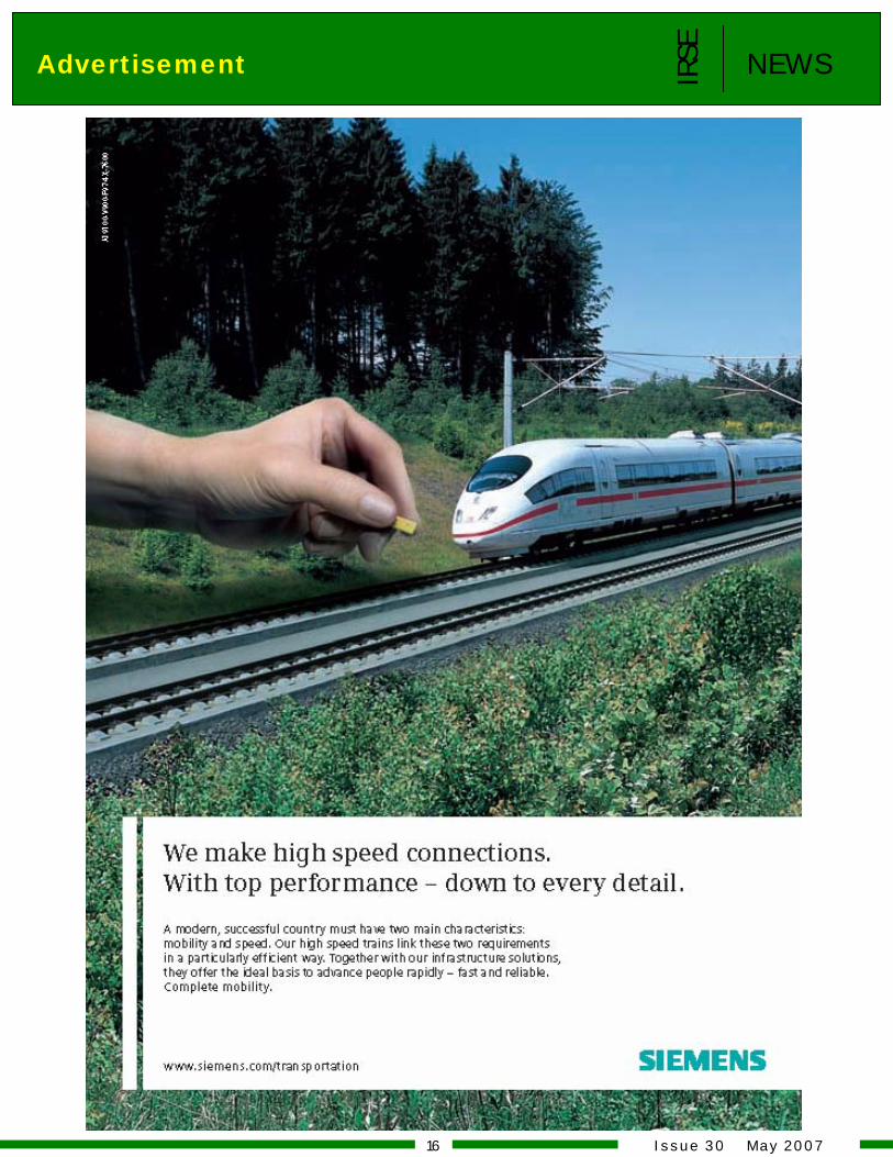
Advertisement
16 I s s u e 3 0 M a y 2 0 0 7
Happy Birthday! Our best wishes to the following IRSE (HK Section) members.
Members Corner IRSE
N E W S
17 I s s u e 3 0 M a y 2 0 0 7
IRSE
Interesting Signals No.90 Minffordd
Interesting Signals
By Peter Matthews
N E W S
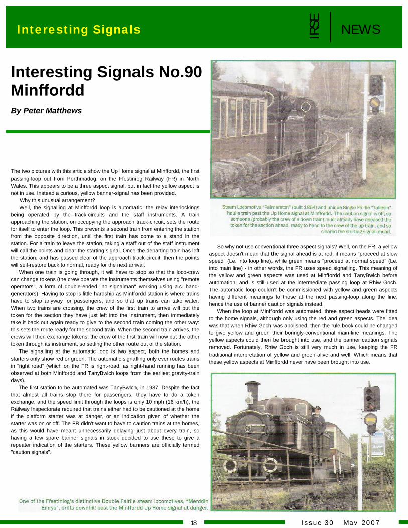
The two pictures with this article show the Up Home signal at Minffordd, the first passing-loop out from Porthmadog, on the Ffestiniog Railway (FR) in North Wales. This appears to be a three aspect signal, but in fact the yellow aspect is not in use. Instead a curious, yellow banner-signal has been provided. Why this unusual arrangement? Well, the signalling at Minffordd loop is automatic, the relay interlockings being operated by the track-circuits and the staff instruments. A train approaching the station, on occupying the approach track-circuit, sets the route for itself to enter the loop. This prevents a second train from entering the station from the opposite direction, until the first train has come to a stand in the station. For a train to leave the station, taking a staff out of the staff instrument will call the points and clear the starting signal. Once the departing train has left the station, and has passed clear of the approach track-circuit, then the points will self-restore back to normal, ready for the next arrival.
When one train is going through, it will have to stop so that the loco-crew can change tokens (the crew operate the instruments themselves using "remote operators", a form of double-ended "no signalman" working using a.c. hand-generators). Having to stop is little hardship as Minffordd station is where trains have to stop anyway for passengers, and so that up trains can take water. When two trains are crossing, the crew of the first train to arrive will put the token for the section they have just left into the instrument, then immediately take it back out again ready to give to the second train coming the other way: this sets the route ready for the second train. When the second train arrives, the crews will then exchange tokens; the crew of the first train will now put the other token through its instrument, so setting the other route out of the station.
The signalling at the automatic loop is two aspect, both the homes and starters only show red or green. The automatic signalling only ever routes trains in "right road" (which on the FR is right-road, as right-hand running has been observed at both Minffordd and TanyBwlch loops from the earliest gravity-train days).
The first station to be automated was TanyBwlch, in 1987. Despite the fact that almost all trains stop there for passengers, they have to do a token exchange, and the speed limit through the loops is only 10 mph (16 km/h), the Railway Inspectorate required that trains either had to be cautioned at the home if the platform starter was at danger, or an indication given of whether the starter was on or off. The FR didn't want to have to caution trains at the homes, as this would have meant unnecessarily delaying just about every train, so having a few spare banner signals in stock decided to use these to give a repeater indication of the starters. These yellow banners are officially termed "caution signals".
So why not use conventional three aspect signals? Well, on the FR, a yellow aspect doesn't mean that the signal ahead is at red, it means "proceed at slow speed" (Le. into loop line), while green means "proceed at normal speed" (Le. into main line) - in other words, the FR uses speed signalling. This meaning of the yellow and green aspects was used at Minffordd and TanyBwlch before automation, and is still used at the intermediate passing loop at Rhiw Goch. The automatic loop couldn't be commissioned with yellow and green aspects having different meanings to those at the next passing-loop along the line, hence the use of banner caution signals instead.
When the loop at Minffordd was automated, three aspect heads were fitted to the home signals, although only using the red and green aspects. The idea was that when Rhiw Goch was abolished, then the rule book could be changed to give yellow and green their boringly-conventional main-line meanings. The yellow aspects could then be brought into use, and the banner caution signals removed. Fortunately, Rhiw Goch is still very much in use, keeping the FR traditional interpretation of yellow and green alive and well. Which means that these yellow aspects at Minffordd never have been brought into use.
I s s u e 3 0 M a y 2 0 0 718
.
Please if you move drop a note, fax , call or email to the IRSE office . Also for up to date information about the institution or
To all members: If you have change address , employers. Don’t assume the IRSE knows where you are. You can miss out on receiving institution mail because they fail to notify their change of address.
its activities, or to download a membership application form log on to the IRSE (HK Section) website http://www.irse.org..hk
Myla Pilarta-Li Editor
IRSE
N E W SEditor Column
IRSE News Letter is published monthly by Institution of Railway Signal Engineers (Hong Kong Section). All rights reserved. Photocopying or reproduction in any form without the written permission of the publisher is strictly prohibited. While every effort has been made to ensure accuracy, no liability is accepted for errors or omission herein. The Team Players: Myla Pilarta-Li Francis Hui KC Lam Enoch Li Lawrence Tam Ground Control: 10/F, MTR Tower, Telford Plaza, Kowloon Bay, Hong Kong Advertising Info: Tel: (852) 2993 3264 Fax: (852) 2993 7728 Email: [email protected]: http://www.irse.org.hk/
19 I s s u e 3 0 M a y 2 0 0 7
IRSE
N E W S Advertisement
20
I s s u e 3 0 M a y 2 0 0 7