Embed Size (px)
Citation preview

Achieving Bipedal Locomotion on Rough Terrainthrough Human-Inspired Control
Shishir Kolathaya and Aaron D. AmesTexas A&M University
College Station, TX, [email protected], [email protected]
Abstract — This paper presents a method for achieving roboticwalking on rough terrain through Human-Inspired Control. Thiscontrol methodology uses human data to achieve human like walkingin robots by considering outputs that appear to be indicative ofwalking, and using nonlinear control methods to track a set offunctions called Canonical Walking Functions (CWF). While thismethod has proven successful on a specific well-defined terrain, roughterrain walking is achieved by dynamically changing the CWF thatthe robot outputs should track at every step. To make the computationmore tractable Extended Canonical Walking Functions (ECWF) areused to generate these desired functions instead of CWF. The stateof the robot, after every non-stance foot strike, is actively sensedand a new CWF is constructed to ensure Hybrid Zero Dynamicsis respected for the next step. Finally, the technique developed isimplemented on different terrains in simulation. The same techniqueis adopted experimentally on the bipedal robot AMBER and testedon sinusoidal terrain. Experimental results show how the walking gaitmorphs based upon the terrain, thereby justifying the theory applied.
Keywords: Bipedal robotic walking, rough terrain naviga-tion, human-inspired control
I. INTRODUCTION
Inspired by the capacity to navigate over rough terrain,bipedal walking represents a challenge in itself in disasterscenarios. Bipedal robots are one of the best means of lo-comotion (if not the best) on any random terrain, since theyhave a very small footprint and can display a wide variety ofmotion primitives to address the difficult problems associatedwith motion planning.
Despite the fact that the problem of walking on a randomterrain is seemingly simple to humans, it remains a difficultproblem to solve in the context of bipedal robots. Out of themany approaches used, the concept of Zero Moment Point([11]) is popular and has been used extensively. But, thistechnique assumes that the robot has feet and they are flat allthe time (which is very “un-human-like”). Walking has alsobeen studied by viewing the robot as an inverted pendulum in[6], [10], and [5], [9] uses the idea of passive dynamic walkingin robots. [12] uses the concept of Hybrid Zero Dynamicsto create a low dimensional representation that yields stablewalking with point feet. Motivated by Hybrid Zero Dynamics,Human-Inspired Control was introduced in order to createmore human-like walking gaits through the use of human-inspired output functions, and achieve flat-ground walking
with AMBER [3], [13]. Human-Inspired Control is heavilyinfluenced by the way humans actuate their joints throughCentral Pattern Generators (CPG) to realize walking (see [8]).The idea is to track a set of functions (termed CanonicalWalking Functions (CWF)) which emulate the trajectories ofhuman walking. While these methods have been utilized toachieve rough terrain walking through the inherent robustnessof the human-inspired controllers, the current framework lacksa formal way for addressing rough terrain locomotion in thecontext of human-inspired control.
This paper presents a method to address this gap byusing the concept of Intermediate Motion Transitions alongwith Human-Inspired Control. We argue that, depending onthe terrain, appropriate patterns are injected during humanlocomotion to get the “right” kind of walking. Here “right”could mean stability, power consumption, speed of execution,feasibility etc. (flat-ground walking that was achieved withAMBER [13] can be considered to be one such pattern).Since the list of possibilities of a terrain is never ending, itis not possible to store infinitely large number of patterns inthe robot. Hence, we claim that for a specific terrain withsmall variations, we can generate patterns (or CWF) from thereference walking function dynamically, and the extent of thevariations are decided by the feasibility of implementation andstability of the robot. In this paper, we choose flat ground, anduse the reference CWF for flat ground (obtained from [13]).The walking is achieved in such a way that it respects HybridZero Dynamics; this implies that the actuated outputs of therobot are tracking the desired functions even through impacts.Then, we allow small perturbations in the terrain, i.e., allowsmall changes in slopes (γ) and generate new CWF in such away that it brings it back to normal flat ground walking mode.
This paper begins with a description of the bipedal robotAMBER and its model in Section II; we then give a briefoverview of the control strategy used to achieve walking insimulation. Section III describes our method for achievingparameters for these human-inspired controllers by reviewingthe optimization and related constructions used to find theseparameters. In Section IV, our method for computing ECWFthat allow for transitions back to nominal walking behaviors ispresented. Finally, the method for computing the intermediatesurfaces for rough terrain is implemented in AMBER andanalyzed in Section V.
II. ROBOT MODELING AND CONTROL
Walking involves alternating phases of continuous anddiscrete dynamics. Hence it is modeled as a hybrid controlsystem H C = (X ,U,S,∆, f ,g) (see [3], [4] for a formaldefinition). For our planar robot, AMBER, which has 5 links(2 calves, 2 thighs and a torso, see Fig. 1), we can definethe configuration space Q, defined by the joint angles: θ =(θs f ,θsk,θsh,θnsh,θnsk)
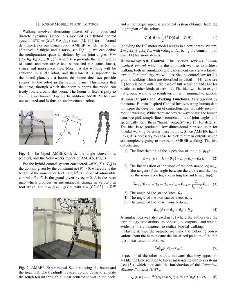
T , where θ represents the joint anglesof stance and non-stance feet, stance and non-stance knees,stance and non-stance hips. Note that the walking will beachieved in a 2D robot, and therefore it is supported inthe lateral plane via a boom; this boom does not providesupport to the robot in the sagittal plane. This means thatthe torso, through which the boom supports the robot, canfreely rotate around the boom. The boom is fixed rigidly toa sliding mechanism (Fig. 2). In addition, AMBER’s feet arenot actuated and is thus an underactuated robot.
z
x
èsf
èsh
ènsh
èsk
ènsk
Fig. 1: The biped AMBER (left), the angle conventions(center), and the SolidWorks model of AMBER (right).
For the hybrid control system considered, H C , X ⊂ T Q isthe domain given by the constraint hR(θ)≥ 0, where hR is theheight of the non-stance foot, U ⊂R4 is the set of admissiblecontrols, S ⊂ X is the guard given by hR = 0, ∆ is the resetmap which provides an instantaneous change in velocity atfoot strike, and x = f (x)+ g(x)u, with x = (θ T , θ T )T ∈ R10
Fig. 2: AMBER Experimental Setup showing the boom andthe treadmill. The treadmill is raised up and down to emulatethe rough terrain through a linear actuator shown in the back.
and u the torque input, is a control system obtained from theLagrangian of the robot:
L(θ , θ) =12
θT D(θ)θ −V (θ). (1)
Including the DC motor model results in a new control system:x = fv(x)+gv(x)Vin, with voltage, Vin, being the control input.See [14] for more details.Human-Inspired Control. This section reviews human-inspired control which is the approach we use to achievewalking both in simulation and experiment on a given knownterrain. For simplicity, we will describe the control law for flatground walking which are described in detail in [4] (also see[3] for related results in the case of full actuation and [14] forresults on other kinds of terrains). The idea will be to extendflat ground walking to rough terrain with minimal variations.Human Outputs and Walking Functions. As suggested bythe name, Human-Inspired Control involves using human datato inspire the development of controllers that provably result inrobotic walking. While there are several ways to use the humandata, we pick simple linear combinations of joint angles andspecifically term them “human outputs” (see [3] for details).The idea is to produce a low-dimensional representation forbipedal walking by using these outputs. Since AMBER has 5links, it is necessary to chose to pick 5 human outputs whichare completely going to represent AMBER walking. The fiveoutputs are:
1) The linearization of the x-position of the hip, phip:
δ phip(θ) = Lc(−θs f )+Lt(−θs f −θsk), (2)
2) The linearization of the slope of the non-stance leg mnsl ,(the tangent of the angle between the z-axis and the lineon the non-stance leg connecting the ankle and hip):
δmnsl(θ) =−θs f −θsk−θsh +θnsh +Lc
Lc +Ltθnsk. (3)
3) The angle of the stance knee, θsk,4) The angle of the non-stance knee, θnsk,5) The angle of the torso from vertical,
θtor(θ) = θs f +θsk +θsh. (4)
A similar idea was also used in [7] where the authors use theterminology “constraints” as opposed to “outputs”, and which,evidently, are constrained to realize bipedal walking.
Having defined the outputs, we make the following obser-vations from the human data: the linearized position of the hipis a linear function of time:
δ pdhip(t,v) = vhipt, (5)
Inspection of the other outputs indicates that they appear toact like the time solution to linear mass-spring-damper systems(see [3]), which motivates the introduction of the CanonicalWalking Function (CWF):
yH(t,α) = e−α4t(α1 cos(α2t)+α3 sin(α2t))+α5. (6)
Human-Inspired Outputs. Having defined the outputs, wecan construct a controller that drives four of the outputsof the robot (hip position is omitted since AMBER is anunderactuated robot and it is not possible to drive five outputswith four actuators) to the outputs of the human, as representedby the CWF: ya(θ(t))→ yd(t,α), with:
yd(t,α) = [yH(t,αnsl),yH(t,αsk),yH(t,αnsk),yH(t,αtor)]T ,
ya(θ) = [δmnsl(θ),θsk,θnsk,θtor(θ)]T , (7)
where yH(t,αi), i ∈ {nsl,sk,nsk, tor} is the CWF (6) butwith parameters αi specific to the output being considered.Grouping these parameters with the velocity of the hip, vhip,that appears in (5), results in the vector of parameters α =(vhip,αnsl ,αsk,αnsk,αtor) ∈ R21.
We can remove the dependence of time in yd(t,α) basedupon the fact that the (linearized) position of the hip isaccurately described by a linear function of time:
τ(θ) = (δ pRhip(θ)−δ pR
hip(θ+))/vhip, (8)
where δ pRhip(θ
+) is the linearized position of the hip at thebeginning of a step. θ+ is the configuration where the heightof the non-stance foot is zero, i.e., hγ(θ
+) = 0. Using (8), wedefine the following human-inspired output:
yα(θ) = ya(θ)− yd(τ(θ),α). (9)
Control Law Construction. The outputs were chosen so thatthe decoupling matrix, A(θ , θ) = LgL f yα(θ , θ) with L theLie derivative, is nonsingular. Therefore, we can define thefollowing torque controller:
u(α,ε)(θ , θ) = (10)
−A−1(θ , θ)(L2
f yα(θ , θ)+2εL f yα(θ , θ)+ ε2yα(θ)
).
In other words, we can apply feedback linearization to obtainthe linear system on the human-inspired output: yα =−2ε yα−ε2yα . More details can be found in [13]
III. HUMAN-INSPIRED HYBRID ZERO DYNAMICS (HZD)
The goal of the human-inspired controller (10) was to drivethe outputs of the robot to the outputs of the human: ya→ ydas t→ ∞. Yet due to the occurrence of the impact with everystep, this may not be true all the time. Therefore, the goalof this section is to find the CWF for which this is satisfied;the end result is that these outputs will define the hybrid zerodynamics surface.Problem Statement. Since AMBER is underactuated, θs f andθs f cannot be controlled. This leads to the notion of usingthe zero dynamics surface which has a dimension of 2. Thecontrol law is applied in such a way that the controllableoutputs are forced to 0 as t→∞. As long as these outputs areexponentially stable, we can realize a surface which representsbipedal robotic walking. Therefore, with the human-inspiredcontroller applied, we say that the controller renders the zerodynamics surface:
Zα = {(θ , θ) ∈ T Q : yα(θ) = 0, L f yα(θ , θ) = 0} (11)
exponentially stable; moreover, this surface is invariant forthe continuous dynamics. Note that here 0 ∈ R4 is a vectorof zeros and we make the dependence of Zα on the set ofparameters explicit. It is at this point that continuous systemsand hybrid systems diverge: while this surface is invariantfor the continuous dynamics, it is not necessarily invariantfor the hybrid dynamics. In particular, the discrete impactsin the system cause the state to be “thrown” off of the zerodynamics surface. Therefore, a hybrid system has Hybrid ZeroDynamics (HZD) if the zero dynamics are invariant throughimpact: ∆(S∩Zα)⊂ Zα .
The goal of human-inspired HZD is to find parameters α∗
that solve the following constrained optimization problem:
α∗ = argmin
α∈R21CostHD(α) (12)
s.t ∆(S∩Zα)⊂ Zα (HZD)
with CostHD the least squares fit of the CWF with the humandata. This determines the parameters of the CWF that gavethe best fit of the human walking functions to the humanoutput data, but subject to constraints that ensure HZD. To getprovable and physically realizable walking, other constraintsare imposed like non-stance foot height clearance, torque andvelocity constraints (see [13]). The optimization also producesa fixed point (θ(ϑ(α)), θ(ϑ(α))) of the periodic gait whichcan be used to compute the transitions on rough terrain. Spaceconstraints limit the explanation of the guard configuration ofthe robot, ϑ(α), but it can be found in [4].Zero Dynamics. With the control law ensuring HZD, we canexplicitly construct the zero dynamics surface. In particular,we utilize the constructions in [12], reframed in the context ofcanonical human walking functions. In particular, we definethe following coordinates for the zero dynamics:
ξ1 = δ pRhip(θ) =: cθ (13)
ξ2 = D(θ)1,1θ =: γ0(θ)θ
where c ∈ R5×1 is obtained from (2), and D(θ)1,1 is the firstrow of the inertia matrix in (1). Moreover, since ξ1 is just thelinearized position of the hip, which was used to parameterizetime (8), we can write yd(τ(θ)) = yd(ξ1).
Due to the fact that we considered linear output functions,from (2)-(4) we can write ya(θ) = Hθ for H ∈R4×5 with fullrow rank. Therefore, defining
Φ(ξ1) =
[cH
]−1(ξ1
yd(ξ1)
)Ψ(ξ1) =
[γ0(Φ(ξ1))
H− ∂yd(ξ1)∂ξ1
c
]−1(10
)(14)
it follows that for θ = Φ(ξ1) and θ = Ψ(ξ1)ξ2 that (θ , θ) ∈Zα . Finally, the zero dynamics evolve according to the ODE:
ξ1 = κ1(ξ1)ξ2 κ1(ξ1) := cΨ(ξ1) (15)
ξ2 = κ2(ξ1) κ2(ξ1) :=∂V (θ)
∂θs f
∣∣∣∣θ=Φ(ξ1)
with V the potential energy of the robot obtained from (1).
IV. WALKING ON ROUGH TERRAIN
This section will introduce the methods adopted to achieveHybrid Zero Dynamics on rough terrain. On flat ground, thezero dynamics surface (Zα ) derived from the CWF (α) isrespected i.e., the robot will exhibit Hybrid Zero Dynamics.When the non-stance foot hits the ground, we say that therobot strikes the guard, S. But, on an uneven terrain, therobot could strike a different guard, Sint , altogether, i.e., whenthe non-stance foot hits the ground at a height hR 6= 0, thenthe resulting post-impact state, x+ = (θ+, θ+), may not beon the same surface. This calls for defining a new set ofCWF in such a way that the post-impact state of the robotresides on the resulting new zero dynamics surface (call it theintermediate zero dynamics surface, Zα
int ). This effectivelyreduces the problem to finding the new CWF, the resultingintermediate zero dynamics surface for which contains thepost-impact state. Given the post-impact state obtained dueto the non-zero height (hR) of non-stance foot, x+, we findthe new CWF by computing the new set of parameters for thenext step, α int .
Extended Canonical Walking Function (ECWF). Given thecanonical walking function in (6), we have the robot outputsand their derivatives:
ya(θ+) = Hθ
+, dya(q+) =Hθ+
ξ+1
, (16)
where ξ+1 = cθ+ (from (13)) is the post-impact hip velocity
and dya is effectively the derivative of the outputs dividedby the post-impact hip velocity. The reason for dividing bythe hip velocity is to make the outputs independent of thehip velocity and based on the fact that if HZD is respectedfor one hip velocity on the guard (S∩Zα ), then it must berespected for all hip velocities on the same guard (S∩Zα ).This is proved in [12] for the case of underactuated walking.
We can design α int in such a way that it brings the stateof the robot back to the zero dynamics surface for flat groundwalking. To be more precise, if the next step were to occuron flat ground, then the intermediate surface, Zα
int , will leadthe state of the robot back to the original surface Zα . In otherwords, the construction of α int will allow the guard of Zα
int
to intersect with the guard of Zα .The end of the step for flat ground walking, x− = (θ−, θ−),
can be computed from, x− = (θ(ϑ(α)), θ(ϑ(α))). The corre-sponding outputs and their derivatives are:
ya(θ−) = Hθ
−, dya(θ−) =
Hθ−
ξ−1
, (17)
with ξ−1 = cθ− being the hip velocity at the end of the step
(again, the end of this intermediate step is assumed to be onflat ground).
Since the desired outputs should equal the outputs of therobot to ensure hybrid invariance, the goal will be to find α int
for which the following is satisfied:
ya(θ+) = yd(τ(θ
+),α int), dya(θ+) =
∂yd(τ(θ+),α int)
∂ξ+1
,
ya(θ−) = yd(τ(θ
−),α int), dya(θ+) =
∂yd(τ(θ−),α int)
∂ξ−1
,
(18)
where τ is the time parameterized by hip position given in (8).Since there are four outputs, and ya(θ) ∈ R4, (18) has
16 equations with the unknown being α int ∈ R21. Due theway the CWF was constructed, finding a solution (or one ofthe solutions) to the 16 nonlinear complex equations will betime consuming and may not be guaranteed. This motivatesintroducing a new function called the Extended CanonicalWalking Function (ECWF):
yHe(t,α) = e−α4t(α1 cos(α2t)+α3 sin(α2t))+α5 cos(α6t)+2α5α4α2
α22 +α2
4 −α26
sin(α6t)+α7,
(19)
which has seven parameters and four of the parameters can bewritten in vector form, αv = [α1,α3,α5, α7]
T which are linearin the expression and can be separated out in the followingmanner:
LTV (t,α) =
e−α4t cos(α2t),e−α4t sin(α2t),
cos(α6t)+ 2α4α6α2
2+α24−α2
6sin(α6t),
1
,yHe(t,α) = LTV T (t,α)αv, (20)
where LTV is the linear transformation vector containing theremaining expression which becomes a constant vector bykeeping α2,α4,α6 constant. Similarly, we can define the partialderivative of the desired extended outputs:
LTVd(t,α) =
−α4e−α4t cos(α2t)−α2e−α4t sin(α2t),−α4e−α4t sin(α2t)+α2e−α4t cos(α2t),
−α6 sin(α6t)+ 2α4α26
α22+α2
4−α26
cos(α6t),
0
,dyHe(t,α) =
∂yHe(t,α)
∂ξ1= LTV T
d (t,α)∂ t
∂ξ1αv. (21)
LTVd is the time derivative of LTV ; and from (8) and (13), itfollows that ∂ t
∂ξ1= v−1
hip.We can now use the ECWF, to replace (7) with:
yde(τ,α) =
yHe(τ,αnsl)yHe(τ,αsk)yHe(τ,αnsk)yHe(τ,αtor)
,∂yde(τ,α)
∂ξ1=
dyHe(τ,αnsl)dyHe(τ,αsk)dyHe(τ,αnsk)dyHe(τ,αtor)
, (22)
which is obtained from the new set of parameters, α =(vhip,αnsl ,αsk,αnsk,αtor) ∈ R29. Accordingly, the new desiredoutputs (22) will replace the desired outputs in (18) resulting in16 linear equations with 29 unknowns. Note that the controllaw in (10) will bear no change with yd replaced with ydeand the hybrid invariance will still be valid. By keeping vhipand α2,α4,α6 of all outputs constant, (18) will contain 16unknowns, and can be solved for in a straightforward manner.In other words, α int will contain the new set of parameterswhere α2,α4,α6’s of outputs are same as in α , and others areobtained by solving for (18) through (22). To illustrate, wewill consider one of the outputs, the stance knee angle, θsk,resulting in:
ysk(θ+) = θ
+sk , dysk(θ
+) =θ+sk
ξ+1
,
ysk(θ−) = θ
−sk , dysk(θ
−) =θ−sk
ξ−1
, (23)
and (18) yields:
ysk(θ+) = yHe(τ(θ
+),α intsk ), dysk(θ
+) = dyHe(τ(θ+),α int
sk ),
ysk(θ−) = yHe(τ(θ
−),α intsk ), dysk(θ
−) = dyHe(τ(θ−),α int
sk ).(24)
Applying (20) and (21) to (24) yields:ysk(θ
+)dysk(θ
+)ysk(θ
−)dysk(θ
−)
=
LTV T (τ(θ+),αsk)
LTV Td (τ(θ+),αsk)v−1
hipLTV T (τ(θ−),αsk)
LTV Td (τ(θ−),αsk)v−1
hip
αv, (25)
which yields a unique solution for αv, if the matrix on theR.H.S. of (25) is invertible. The invertibility is maintained bythe choice of α2,α4,α6. This procedure remains the same forthe remaining output parameters.
It is important to note that we can apply this transformationeven when h+R = 0, resulting in the set of parameters α int
matching with the original parameters α . This means that wecan repeatedly apply this transformation irrespective of theheight after every step resulting in HZD on flat ground too.
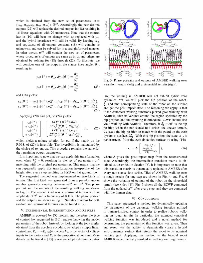
The suggested method was implemented on two kinds ofterrain. The first kind was generated from a pseudo-randomnumber generator varying between −20 and 20. The phaseportrait and the outputs of the resulting walking are shownin Fig. 3. The second kind was a sinusoidal terrain with anamplitude of 20 and a frequency of 0.1Hz. The phase portraitand the outputs are shown in Fig. 3. Simulated videos for bothrandom and sinusoidal terrains can be found at [2].
V. EXPERIMENTAL IMPLEMENTATION AND RESULTS
AMBER is powered by DC motors, and therefore the typeof control law suggested in (10) requires knowing the modelparameters of the robot. Instead, by looking at the joint anglesobtained from the absolute encoders, we adopt a simple linearcontrol law: Vin =−Kpyα(θ), where Vin is the vector of voltageinputs to the motors and Kp is the proportional constant. Moredetails can be found in [13]. Since we adopt a different control
−0.5 0 0.5 1
−6
−4
−2
0
2
4
Angle (rad)
Vel
oci
ty(r
ad/s)
Periodic Orbit - Random Ter
θsf θsk θsh
θnsh θnsk
−0.5 0 0.5 1
−6
−4
−2
0
2
4
Angle (rad)
Vel
oci
ty(r
ad/s)
θsf θsk θsh
θnsh θnsk
0 1 2 3 4 5 6 7 8
−0.2
0
0.2
0.4
0.6
0.8
1
1.2
Time (s)
Outp
uts
δmansl θa
sk θansk θa
to
δmdnsl θd
sk θdnsk θd
to
0 1 2 3 4 5 6 7 8
−0.2
0
0.2
0.4
0.6
0.8
1
1.2
Time (s)
Outp
uts
δmansl θa
sk θansk θa
to
δmdnsl θd
sk θdnsk θd
to
Fig. 3: Phase portraits and outputs of AMBER walking overa random terrain (left) and a sinusoidal terrain (right).
law, the walking in AMBER will not exhibit hybrid zerodynamics. Yet, we will pick the hip position of the robot,ξ1 and find corresponding state of the robot on the surfaceand get the post-impact state. The reasoning we apply is thatif the canonical walking functions picked give walking withAMBER, then its variants around the region specified by thehip position and the resulting intermediate ECWF should alsoyield walking with AMBER. Therefore, if ξ ∗1 = cθ ∗ is the hipposition when the non-stance foot strikes the uneven terrain,we scale the hip position to match with the guard on the zerodynamics surface, kξ ∗1 . With this hip position, the state, x+, isreconstructed from the zero dynamics surface by using (14):
x+ = ∆(
[Φ(kξ ∗1 )
∂Φ(kξ ∗1 )∂ξ ∗1
vhip
]), (26)
where ∆ gives the post-impact map from the reconstructedstate. Accordingly, the intermediate transition matrix is ob-tained as described in Section IV. It is important to note thatthis transition matrix is dynamically updated in AMBER afterevery non-stance foot strike. Tiles of AMBER walking overa rough terrain for one step are shown in Fig. 4, and Fig. 6shows the variation of outputs of the robot on the sinusoidalterrain (see video [1]). Fig. 5 shows all the ECWF computedfrom the updated α int after every step, and they are comparedwith the human data.
VI. CONCLUSIONS
This paper presented a method for dynamically updatingthe parameters of the canonical walking function utilizedin human-inspired control in order to realize robotic walk-ing on rough terrain. In particular, the extended canonicalwalking function was introduced and a novel method fordetermining the parameters of this function was given. Thenend result was the ability to dynamically create a hybridzero dynamics surface that returns the robot to its nominalwalking gait. Applying this method to the bipedal robotAMBER experimentally resulted in walking on rough terrain.
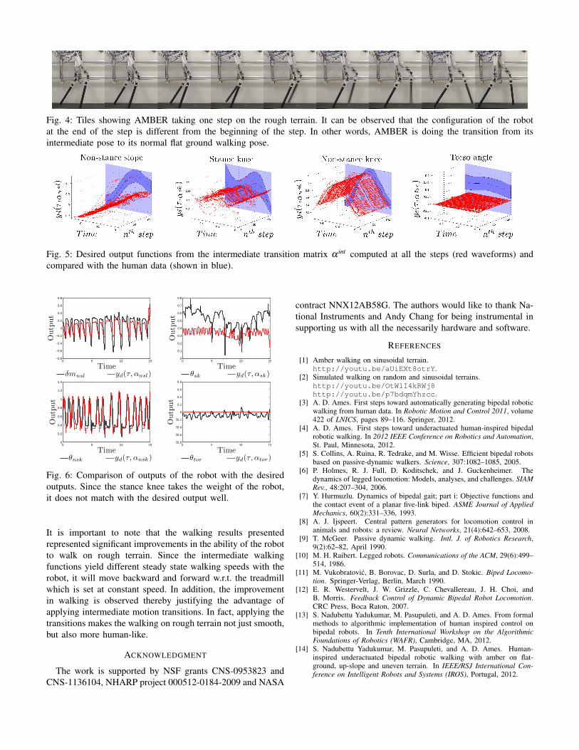
Fig. 4: Tiles showing AMBER taking one step on the rough terrain. It can be observed that the configuration of the robotat the end of the step is different from the beginning of the step. In other words, AMBER is doing the transition from itsintermediate pose to its normal flat ground walking pose.
Fig. 5: Desired output functions from the intermediate transition matrix α int computed at all the steps (red waveforms) andcompared with the human data (shown in blue).
0 5 10 15−0.8
−0.6
−0.4
−0.2
0
0.2
0.4
0.6
0.8
Time
Outp
ut
δmnsl
yd(τ, αnsl)
0 5 10 150
0.1
0.2
0.3
0.4
0.5
0.6
0.7
0.8
Time
Outp
ut
θsk
yd(τ, αsk)
0 5 10 150
0.2
0.4
0.6
0.8
1
1.2
1.4
Time
Outp
ut
θnsk
yd(τ, αnsk)
0 5 10 15−0.8
−0.6
−0.4
−0.2
0
0.2
0.4
0.6
0.8
Time
Outp
ut
θtor
yd(τ, αtor)
Fig. 6: Comparison of outputs of the robot with the desiredoutputs. Since the stance knee takes the weight of the robot,it does not match with the desired output well.
It is important to note that the walking results presentedrepresented significant improvements in the ability of the robotto walk on rough terrain. Since the intermediate walkingfunctions yield different steady state walking speeds with therobot, it will move backward and forward w.r.t. the treadmillwhich is set at constant speed. In addition, the improvementin walking is observed thereby justifying the advantage ofapplying intermediate motion transitions. In fact, applying thetransitions makes the walking on rough terrain not just smooth,but also more human-like.
ACKNOWLEDGMENT
The work is supported by NSF grants CNS-0953823 andCNS-1136104, NHARP project 000512-0184-2009 and NASA
contract NNX12AB58G. The authors would like to thank Na-tional Instruments and Andy Chang for being instrumental insupporting us with all the necessarily hardware and software.
REFERENCES
[1] Amber walking on sinusoidal terrain.http://youtu.be/aUiEXt8otrY.
[2] Simulated walking on random and sinusoidal terrains.http://youtu.be/OtW1I4kRWj8http://youtu.be/p7bdqmYhzcc.
[3] A. D. Ames. First steps toward automatically generating bipedal roboticwalking from human data. In Robotic Motion and Control 2011, volume422 of LNICS, pages 89–116. Springer, 2012.
[4] A. D. Ames. First steps toward underactuated human-inspired bipedalrobotic walking. In 2012 IEEE Conference on Robotics and Automation,St. Paul, Minnesota, 2012.
[5] S. Collins, A. Ruina, R. Tedrake, and M. Wisse. Efficient bipedal robotsbased on passive-dynamic walkers. Science, 307:1082–1085, 2005.
[6] P. Holmes, R. J. Full, D. Koditschek, and J. Guckenheimer. Thedynamics of legged locomotion: Models, analyses, and challenges. SIAMRev., 48:207–304, 2006.
[7] Y. Hurmuzlu. Dynamics of bipedal gait; part i: Objective functions andthe contact event of a planar five-link biped. ASME Journal of AppliedMechanics, 60(2):331–336, 1993.
[8] A. J. Ijspeert. Central pattern generators for locomotion control inanimals and robots: a review. Neural Networks, 21(4):642–653, 2008.
[9] T. McGeer. Passive dynamic walking. Intl. J. of Robotics Research,9(2):62–82, April 1990.
[10] M. H. Raibert. Legged robots. Communications of the ACM, 29(6):499–514, 1986.
[11] M. Vukobratovic, B. Borovac, D. Surla, and D. Stokic. Biped Locomo-tion. Springer-Verlag, Berlin, March 1990.
[12] E. R. Westervelt, J. W. Grizzle, C. Chevallereau, J. H. Choi, andB. Morris. Feedback Control of Dynamic Bipedal Robot Locomotion.CRC Press, Boca Raton, 2007.
[13] S. Nadubettu Yadukumar, M. Pasupuleti, and A. D. Ames. From formalmethods to algorithmic implementation of human inspired control onbipedal robots. In Tenth International Workshop on the AlgorithmicFoundations of Robotics (WAFR), Cambridge, MA, 2012.
[14] S. Nadubettu Yadukumar, M. Pasupuleti, and A. D. Ames. Human-inspired underactuated bipedal robotic walking with amber on flat-ground, up-slope and uneven terrain. In IEEE/RSJ International Con-ference on Intelligent Robots and Systems (IROS), Portugal, 2012.


![[JIRS-2008] a Novel Method of Gait Synthesis for Bipedal Fast Locomotion](https://img.pdfslide.us/doc/110x75/577d38e91a28ab3a6b98bbf9/jirs-2008-a-novel-method-of-gait-synthesis-for-bipedal-fast-locomotion.jpg)