Embed Size (px)
Citation preview

Before installing or using your solar air conditioner, please print and read this manual carefully
and keep it for future reference.
Please read this installation manual completely before installing the product. If the power cord is damaged,
replacement must be performed by authorized personnel only. Installation work must be performed in accordance
with the NEC and local codes. You should contact a licensed service technician for installation, repair, or maintenance.
Improper installation could damage the system and/or void the warranty and could result in injury, death, or property
damage.
.
Notice To Owner/Installer:
This unit is designed for easy installation by an experienced person. It is legal for a
homeowner to install it, however we highly recommend using a licensed HVAC
technician for installation.
Legal Information About Self-Installing R410A Air Conditioners
Can a homeowner install this system?
Yes, a homeowner with a vacuum pump, proper training, and equipment can install this unit. Unless
you are experienced with installing air conditioners we recommend you hire a professional installer. The
person who installs the system must do all work in compliance with local building and electrical codes.
Are there any restrictions on the purchase of R410A refrigerants?
R410a is not an ozone-depleting substance. At this time the purchase of R410a refrigerant is not restricted
in the US. There is no technician certification requirement for those that purchase HFC refrigerants, such as
R-410a or R-134a. If you are not licensed, some local HVAC supply companies may refuse to sell you
R410a based on a misunderstanding of the law, or because they wish to discourage homeowners from
working on their own systems.
Are there any restrictions on the use of R410A refrigerants?
Yes, it is illegal to knowingly vent or release these refrigerants. The venting prohibition applies to R410a,
and all other HFC refrigerants, just as it does for ozone-depleting refrigerants like R-22.
Is EPA technician certification required to service R410A systems?
No, at this time EPA technician certification is not required in order to service R-410a systems.
Source: http://www.epa.gov/ozone/title6/phaseout/technicians_contractors_faq.html
ACDC12 Solar Air Conditioner
Heat Pump
Model ACDC12 Solar Heating & Cooling Heat Pump Mini-Split System
Installation Manual

CONTENTS
SAFETY PRECAUTIONS Warning 2
Caution 2
Selecting installation location 3
Accessories 4
Indoor unit installation 5
Outdoor unit installation 7
Refrigerant tube connection 8
Electrical work 9
Installation of the solar photovoltaic system 12
Wiring the MNPV3 21
Grounding Principals 22
2 Panel Grounding 23
3 panel Grounding 24
Safety and leakage check 24
Evacuation of line set 27
Testing 28
Please Print & Read This Manual Inside you will find many helpful hints on how to install and test the air conditioner properly.
CAUTION
Contact an authorized service technician for repair or maintenance of this unit.
Only allow a qualified person to install this unit.
The air conditioner is not intended for use by young children without supervision.
Young children should be supervised to ensure that they do not play with the air conditioner.
If the power cord is to be replaced, replacement work must be performed by authorized personnel only.
Installation work must be performed in accordance with local building and electrical codes.
1
SAFETY PRECAUTIONS
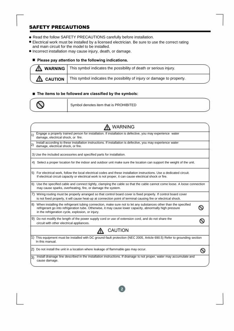
Read the follow SAFETY PRECAUTIONS carefully before installation.
Electrical work must be installed by a licensed electrician. Be sure to use the correct rating and main circuit for the model to be installed. Incorrect installation may cause injury, death, or damage.
Please pay attention to the following indications.
WARNING
This symbol indicates the possibility of death or serious injury.
CAUTION
This symbol indicates the possibility of injury or damage to property.
The items to be followed are classified by the symbols:
Symbol denotes item that is PROHIBITED
WARNING
1)
Engage a properly trained person for installation. If installation is defective, you may experience water
damage, electrical shock, or fire.
2)
Install according to these installation instructions. If installation is defective, you may experience water
damage, electrical shock, or fire.
3) Use the included accessories and specified parts for installation.
4) Select a proper location for the indoor and outdoor unit make sure the location can support the weight of the unit.
5) For electrical work, follow the local electrical codes and these installation instructions. Use a dedicated circuit.
If electrical circuit capacity or electrical work is not proper, it can cause electrical shock or fire.
6) Use the specified cable and connect tightly, clamping the cable so that the cable cannot come loose. A loose connection
may cause sparks, overheating, fire, or damage the system.
7) Wiring routing must be properly arranged so that control board cover is fixed properly. If control board cover
is not fixed properly, it will cause heat-up at connection point of terminal causing fire or electrical shock.
8) When installing the refrigerant tubing connection, make sure not to let any substances other than the specified
refrigerant go into refrigeration tube. Otherwise, it may cause lower capacity, abnormally high pressure
in the refrigeration cycle, explosion, or injury.
9) Do not modify the length of the power supply cord or use of extension cord, and do not share the
circuit with other electrical appliances.
CAUTION
1)
This equipment must be installed with DC ground-fault protection (NEC 2005, Article 690.5) Refer to grounding section
In this manual.
2)
Do not install the unit in a location where leakage of flammable gas may occur.
3)
Install drainage line described in the installation instructions. If drainage is not proper, water may accumulate and
cause damage.
2
2
INSTALLATION INSTRUCTIONS
Selecting installation location
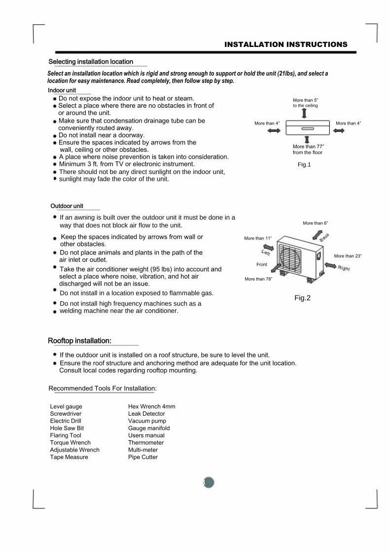
Select an installation location which is rigid and strong enough to support or hold the unit (21lbs), and select a location for easy maintenance. Read completely, then follow step by step. Indoor unit
Do not expose the indoor unit to heat or steam. Select a place where there are no obstacles in front of or around the unit. Make sure that condensation drainage tube can be conveniently routed away. Do not install near a doorway. Ensure the spaces indicated by arrows from the wall, ceiling or other obstacles. A place where noise prevention is taken into consideration. Minimum 3 ft. from TV or electronic instrument. There should not be any direct sunlight on the indoor unit, sunlight may fade the color of the unit.
More than 5”
to the ceiling
More than 4” More than 4”
More than 77” from the floor
Fig.1
Outdoor unit
If an awning is built over the outdoor unit it must be done in a
way that does not block air flow to the unit.
Keep the spaces indicated by arrows from wall or other obstacles. Do not place animals and plants in the path of the air inlet or outlet. Take the air conditioner weight (95 lbs) into account and select a place where noise, vibration, and hot air discharged will not be an issue. Do not install in a location exposed to flammable gas. Do not install high frequency machines such as a welding machine near the air conditioner.
Rooftop installation:
More than 6”
More than 11”
More than 23”
Front
More than 78”
Fig.2
If the outdoor unit is installed on a roof structure, be sure to level the unit.
Ensure the roof structure and anchoring method are adequate for the unit location. Consult local codes regarding rooftop mounting.
Recommended Tools For Installation:
Level gauge
Screwdriver
Electric Drill
Hole Saw Bit
Flaring Tool
Torque Wrench
Adjustable Wrench
Tape Measure
Hex Wrench 4mm
Leak Detector
Vacuum pump
Gauge manifold
Users manual
Thermometer
Multi-meter
Pipe Cutter
3

INSTALLATION INSTRUCTIONS
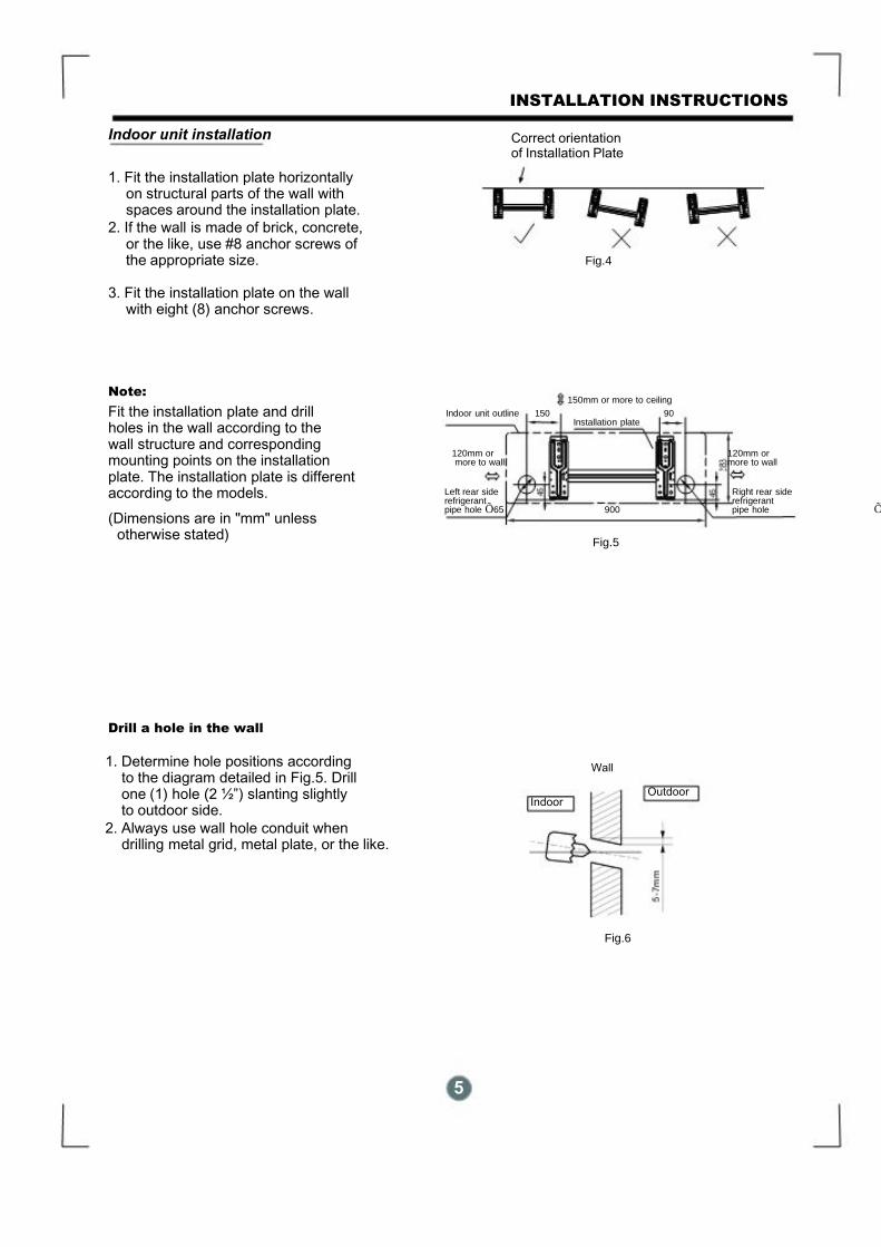
Indoor unit installation
1. Fit the installation plate horizontally on structural parts of the wall with spaces around the installation plate.
2. If the wall is made of brick, concrete, or the like, use #8 anchor screws of
the appropriate size.
3. Fit the installation plate on the wall with eight (8) anchor screws.
Note:
Fit the installation plate and drill holes in the wall according to the wall structure and corresponding mounting points on the installation plate. The installation plate is different according to the models. (Dimensions are in "mm" unless otherwise stated)
Drill a hole in the wall
1. Determine hole positions according to the diagram detailed in Fig.5. Drill one (1) hole (2 ½”) slanting slightly
to outdoor side. 2. Always use wall hole conduit when
drilling metal grid, metal plate, or the like.
Correct orientation of Installation Plate
Fig.4
150mm or more to ceiling Indoor unit outline 150 90
Installation plate
120mm or 120mm or more to wall more to wall
Left rear side Right rear side refrigerant refrigerant pipe hole Õ65 900 pipe hole Õ
Fig.5
Wall
Outdoor Indoor
Fig.6
5

INSTALLATION INSTRUCTIONS
Connective Tube and Drainage
Installation
1. Run the drain hose sloping downward.
Do not install the drain hose as
illustrated in Fig.7.
2. When connecting extension drain hose,
insulate the connecting part of extension drain hose with a shield pipe, do not let
the drain hose slack.
Refrigerant Tube Installation IMPORTANT:
The unit can only use right-hand piping or right rear piping as shown in
Fig.8.
1. Remove the cover for right-hand piping first. 2. For the right rear piping, install the piping as shown in fig. 8 3. Fix the end of the connective pipe. (Refer
to Tightening Connection in REFRIGERANT PIPING CONNECTION)
Indoor unit installation
1. Pass the piping through the hole in the
wall. 2. Put the upper claw at the back of the
indoor unit on the upper hook of the installation plate, move the indoor unit
from side to side to see that it is securely
hooked (see Fig.9 & Fig.10). 3. Piping can easily be made by lifting the
indoor unit with a cushioning material between the indoor unit and the wall.
Remove material after it is not needed.
4. Push the lower part of the indoor unit up
on the wall, then move the indoor unit from side to side, up and down to check
if it is hooked securely.
Do not block water flow by a rise.
Right-hand piping
Fig.8
Upper Hook
Lower Hook
Fig.9
6
Do not put the end of drain hose into water.
Fig.7
Right rear piping
Cushioning
material
Fig.10
INSTALLATION INSTRUCTIONS
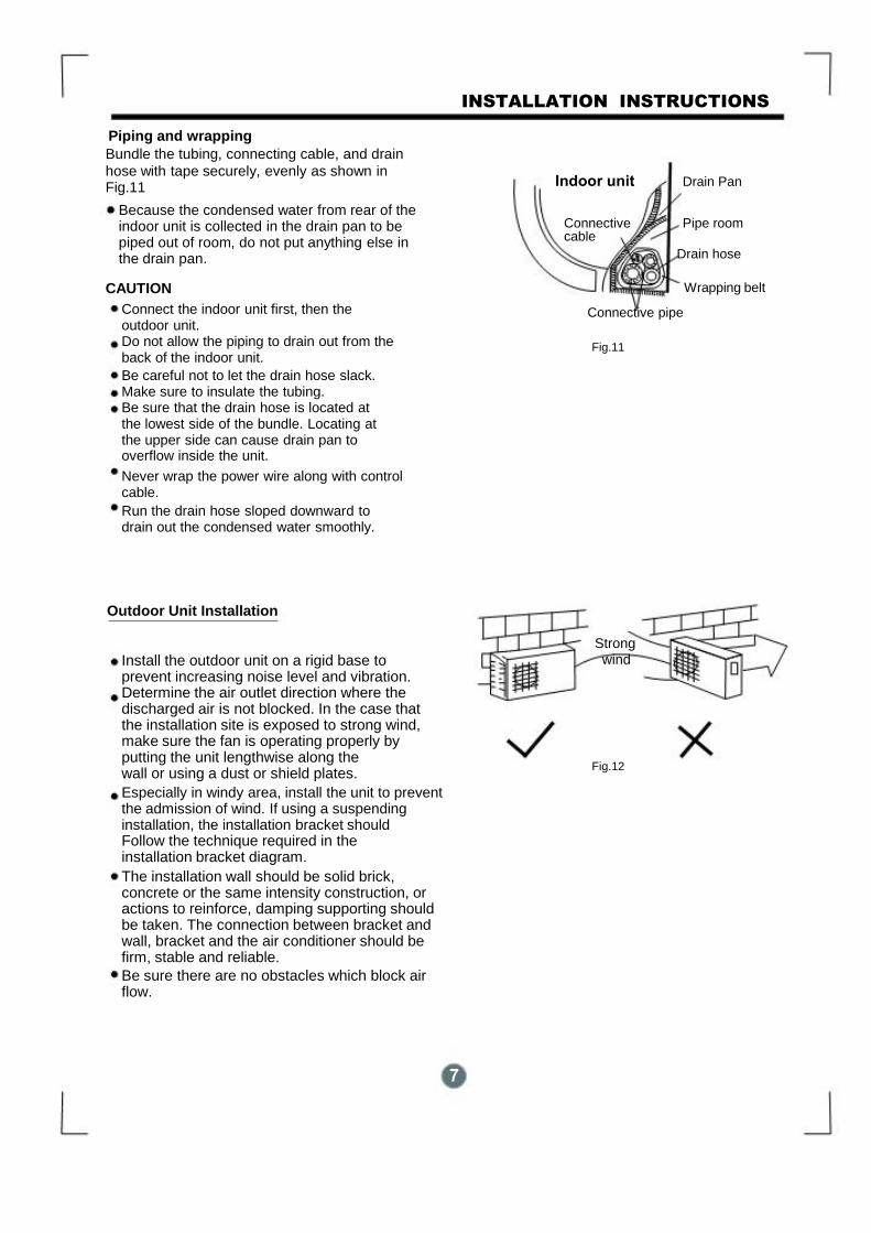
Piping and wrapping Bundle the tubing, connecting cable, and drain
hose with tape securely, evenly as shown in Fig.11
Because the condensed water from rear of the indoor unit is collected in the drain pan to be piped out of room, do not put anything else in the drain pan.
CAUTION
Connect the indoor unit first, then the
outdoor unit. Do not allow the piping to drain out from the
back of the indoor unit. Be careful not to let the drain hose slack. Make sure to insulate the tubing. Be sure that the drain hose is located at the lowest side of the bundle. Locating at the upper side can cause drain pan to overflow inside the unit. Never wrap the power wire along with control cable. Run the drain hose sloped downward to
drain out the condensed water smoothly.
Outdoor Unit Installation
Install the outdoor unit on a rigid base to prevent increasing noise level and vibration. Determine the air outlet direction where the discharged air is not blocked. In the case that the installation site is exposed to strong wind, make sure the fan is operating properly by putting the unit lengthwise along the wall or using a dust or shield plates. Especially in windy area, install the unit to prevent the admission of wind. If using a suspending installation, the installation bracket should Follow the technique required in the installation bracket diagram. The installation wall should be solid brick, concrete or the same intensity construction, or actions to reinforce, damping supporting should be taken. The connection between bracket and wall, bracket and the air conditioner should be firm, stable and reliable. Be sure there are no obstacles which block air flow.
Indoor unit Drain Pan
Connective Pipe room cable Drain hose
Wrapping belt
Connective pipe
Fig.11
Strong
wind
Fig.12
7
REFRIGERANT TUBE CONNECTION
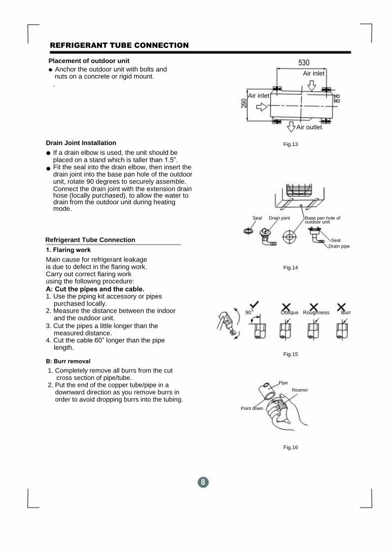
Placement of outdoor unit
Anchor the outdoor unit with bolts and nuts on a concrete or rigid mount. .
Drain Joint Installation If a drain elbow is used, the unit should be
placed on a stand which is taller than 1.5”. Fit the seal into the drain elbow, then insert the drain joint into the base pan hole of the outdoor unit, rotate 90 degrees to securely assemble. Connect the drain joint with the extension drain hose (locally purchased), to allow the water to drain from the outdoor unit during heating mode.
530 Air inlet
Air inlet
Air outlet
Fig.13
Seal Drain joint Base pan hole of outdoor unit
Refrigerant Tube Connection
1. Flaring work Main cause for refrigerant leakage is due to defect in the flaring work. Carry out correct flaring work using the following procedure: A: Cut the pipes and the cable. 1. Use the piping kit accessory or pipes purchased locally. 2. Measure the distance between the indoor and the outdoor unit. 3. Cut the pipes a little longer than the measured distance. 4. Cut the cable 60” longer than the pipe length. B: Burr removal
1. Completely remove all burrs from the cut cross section of pipe/tube. 2. Put the end of the copper tube/pipe in a downward direction as you remove burrs in order to avoid dropping burrs into the tubing.
Seal Drain pipe
Fig.14
£
90 Oblique Roughness Burr
Fig.15
Pipe Reamer
Point down
Fig.16
8
ELECTRICAL WORK
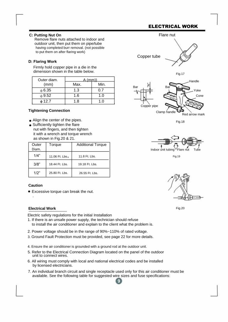
C: Putting Nut On Remove flare nuts attached to indoor and
outdoor unit, then put them on pipe/tube having completed burr removal. (not possible
to put them on after flaring work)
D: Flaring Work Firmly hold copper pipe in a die in the
dimension shown in the table below.
Outer diam. A (mm)) (mm) Max. Min.
6.35 1.3 0.7 9.52 1.6 1.0 12.7 1.8 1.0
Tightening Connection
Flare nut
Copper tube
Fig.17
Handle
Bar Bar
Yoke
Cone
Copper pipe
Clamp handle
Red arrow mark
Align the center of the pipes.
Sufficiently tighten the flare nut with fingers, and then tighten
it with a wrench and torque wrench
as shown in Fig.20 & 21. Outer Torque Additional Torque
Diam.
Fig.18
Indoor unit tubing Flare nut Tube
11.8 Ft. Lbs. Fig.19
12
26.55 Ft. Lbs.
Caution
Excessive torque can break the nut. .
Electrical Work
Fig.20
Electric safety regulations for the initial Installation
1. If there is an unsafe power supply, the technician should refuse
to install the air conditioner and explain to the client what the problem is.
2. Power voltage should be in the range of 90%~110% of rated voltage. 3. Ground Fault Protection must be provided, see page 22 for more details.
4. Ensure the air conditioner is grounded with a ground rod at the outdoor unit.
5. Refer to the Electrical Connection Diagram located on the panel of the outdoor unit to connect wires. 6. All wiring must comply with local and national electrical codes and be installed by licensed electricians. 7. An individual branch circuit and single receptacle used only for this air conditioner must be available. See the following table for suggested wire sizes and fuse specifications: 9
11.06 Ft. Lbs. 18.44 Ft. Lbs. 19.18 Ft. Lbs.
25.80 Ft. Lbs.
1/4”
3/8”
1/2”
ELECTRICAL WORK
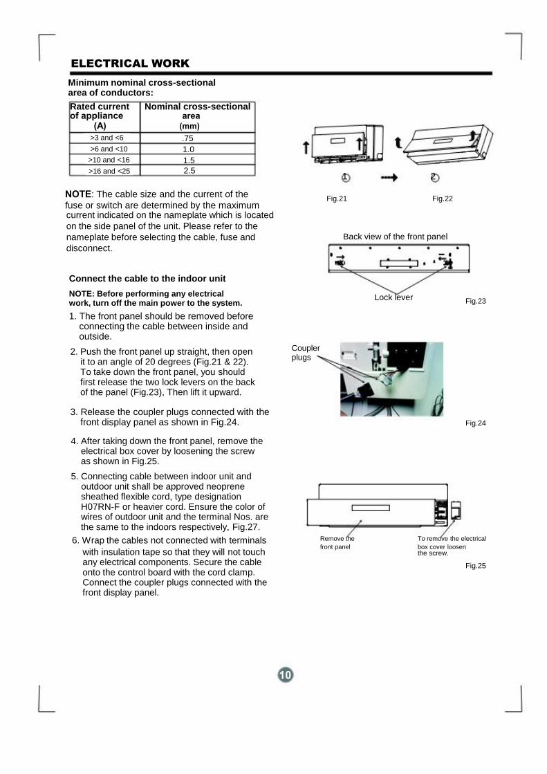
Minimum nominal cross-sectional area of conductors: Rated current Nominal cross-sectional of appliance area (A) (mm)
NOTE: The cable size and the current of the
fuse or switch are determined by the maximum
current indicated on the nameplate which is located
on the side panel of the unit. Please refer to the
nameplate before selecting the cable, fuse and
disconnect.
Connect the cable to the indoor unit
NOTE: Before performing any electrical work, turn off the main power to the system. 1. The front panel should be removed before connecting the cable between inside and outside.
2. Push the front panel up straight, then open it to an angle of 20 degrees (Fig.21 & 22). To take down the front panel, you should first release the two lock levers on the back of the panel (Fig.23), Then lift it upward. 3. Release the coupler plugs connected with the front display panel as shown in Fig.24. 4. After taking down the front panel, remove the electrical box cover by loosening the screw as shown in Fig.25. 5. Connecting cable between indoor unit and outdoor unit shall be approved neoprene sheathed flexible cord, type designation H07RN-F or heavier cord. Ensure the color of wires of outdoor unit and the terminal Nos. are the same to the indoors respectively, Fig.27.
6. Wrap the cables not connected with terminals with insulation tape so that they will not touch
any electrical components. Secure the cable onto the control board with the cord clamp. Connect the coupler plugs connected with the front display panel.
10
1 2
Fig.21 Fig.22
Back view of the front panel
Lock lever
Fig.23
Coupler plugs
Fig.24
Remove the To remove the electrical
front panel box cover loosen the screw.
Fig.25
>16 and <25
>10 and <16
>6 and <10
>3 and <6 .75
1.0
1.5
2.5
ELECTRICAL WORK
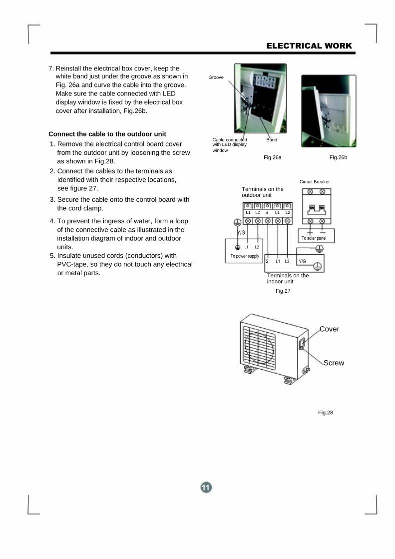
7. Reinstall the electrical box cover, keep the
white band just under the groove as shown in
Fig. 26a and curve the cable into the groove.
Make sure the cable connected with LED
display window is fixed by the electrical box
cover after installation, Fig.26b.
Connect the cable to the outdoor unit
1. Remove the electrical control board cover
from the outdoor unit by loosening the screw
as shown in Fig.28. 2. Connect the cables to the terminals as
identified with their respective locations,
see figure 27.
3. Secure the cable onto the control board with
the cord clamp.
4. To prevent the ingress of water, form a loop
of the connective cable as illustrated in the
installation diagram of indoor and outdoor
units.
5. Insulate unused cords (conductors) with
PVC-tape, so they do not touch any electrical
or metal parts.
Groove
Cable connected Band with LED display window Fig.26a Fig.26b
Circuit Breaker Terminals on the
outdoor unit
OFF OFF
L1 L2 S L1 L2
Y/G
To solar panel
L1 L2
To power supply S L1 L2 Y/G
Terminals on the indoor unit
Fig.27
Cover
Screw
Fig.28
11

ELECTRICAL WORK
Installation of the solar photovoltaic system This guide contains information regarding the installation and safe handling of solar photovoltaic
module. All instructions should be read and understood before attempting to install. If there is
any question, please contact our sales department for further explanation. The installer should
conform to all the safety precautions listed in this guide when installing the module. Local codes
should also be followed in such installations. This manual describes several typical systems of solar photovoltaic, but does not involve the
specific structures and installation procedures of the installation. Please consult the supplier for
the information of the following assemblies: a) the specifications of the solar photovoltaic system b) cable material c) connecting components d) bracket and support e) supporting parts Before installing a solar photovoltaic system, the installer should become familiar with the mechanical and electrical requirement for such a system. Keep this guide in a safe place for
future reference (care and maintenance) and in case of sale or disposal of the module at the
end of its useful life.
General
Installing solar photovoltaic systems may require specialized skills and knowledge. Installation
should be performed only by qualified persons. All modules come with a permanently attached junction box and #12 AWG terminated in Multi-Contact PV-KBT4 (female) or PV-KST4 (male) connectors. The installer should assume the risk of all injury that might occur during installation, including without limitation, the risk of electric shock. The solar photovoltaic electrical energy production system must comply with the following
table for suggested current and voltage specifications:
Maximum Power Voltage (W)
<700W
Optimum operating voltage (Vmp)
<DC32V
Optimum operating voltage (Vmp)
>DC20V
Open-circuit voltage (Vmp)
<DC42V
Short-circuit current (Vmp)
<DC25A
Maximum power current (Pmax)
<DC20A
One individual module may generate DC voltages greater than 30 volts when exposed to direct
sunlight. Contact with a DC voltage of 30V or more is potentially hazardous. Electrical joints such
as the wire terminal will cause sparks, burning or deadly electric shock. Please do not touch such
terminals directly under any circumstances.
Fig.29
12
ELECTRICAL WORK
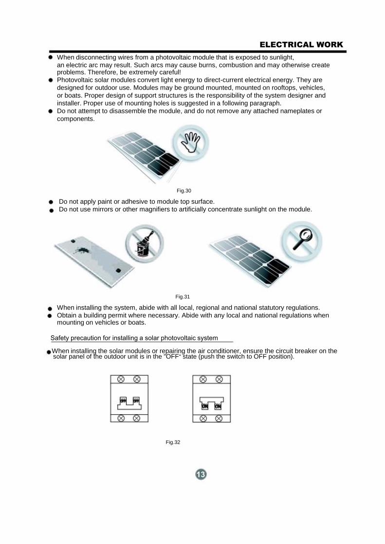
When disconnecting wires from a photovoltaic module that is exposed to sunlight, an electric arc may result. Such arcs may cause burns, combustion and may otherwise create problems. Therefore, be extremely careful! Photovoltaic solar modules convert light energy to direct-current electrical energy. They are
designed for outdoor use. Modules may be ground mounted, mounted on rooftops, vehicles,
or boats. Proper design of support structures is the responsibility of the system designer and
installer. Proper use of mounting holes is suggested in a following paragraph.
Do not attempt to disassemble the module, and do not remove any attached nameplates or
components.
Fig.30
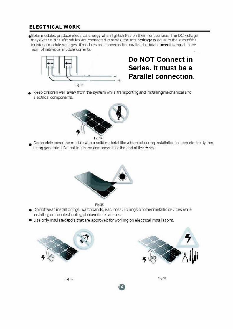
Do not apply paint or adhesive to module top surface. Do not use mirrors or other magnifiers to artificially concentrate sunlight on the module.
Fig.31
When installing the system, abide with all local, regional and national statutory regulations. Obtain a building permit where necessary. Abide with any local and national regulations when mounting on vehicles or boats.
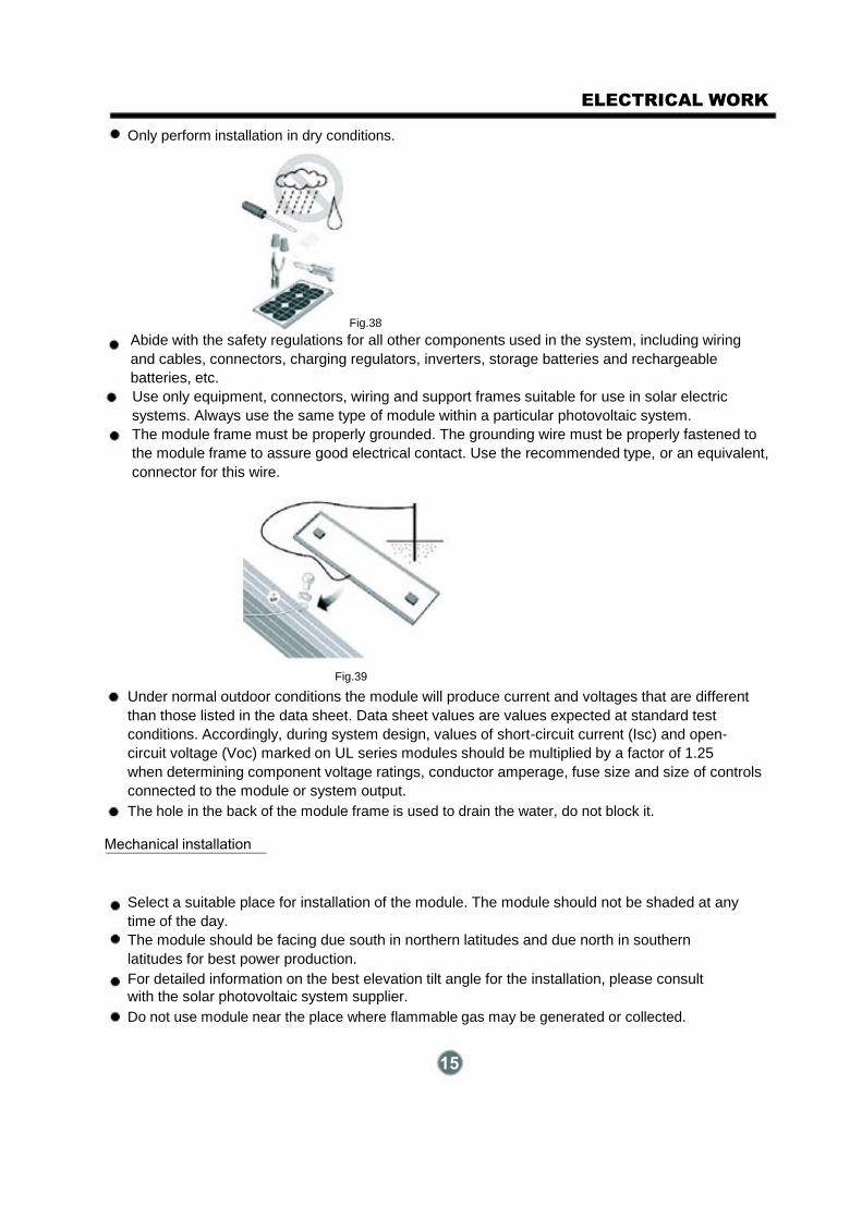
Safety precaution for installing a solar photovoltaic system When installing the solar modules or repairing the air conditioner, ensure the circuit breaker on the solar panel of the outdoor unit is in the "OFF" state (push the switch to OFF position).
OFF OFF ON ON
Fig.32
13
Do NOT Connect in
Series. It must be a
Parallel connection.
ELECTRICAL WORK
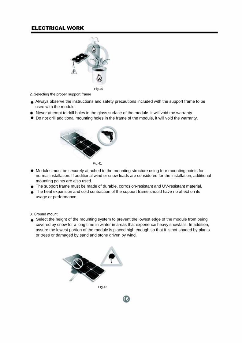
Only perform installation in dry conditions.
Fig.38 Abide with the safety regulations for all other components used in the system, including wiring
and cables, connectors, charging regulators, inverters, storage batteries and rechargeable
batteries, etc.
Use only equipment, connectors, wiring and support frames suitable for use in solar electric
systems. Always use the same type of module within a particular photovoltaic system.
The module frame must be properly grounded. The grounding wire must be properly fastened to
the module frame to assure good electrical contact. Use the recommended type, or an equivalent,
connector for this wire.
Fig.39
Under normal outdoor conditions the module will produce current and voltages that are different
than those listed in the data sheet. Data sheet values are values expected at standard test
conditions. Accordingly, during system design, values of short-circuit current (Isc) and open-
circuit voltage (Voc) marked on UL series modules should be multiplied by a factor of 1.25
when determining component voltage ratings, conductor amperage, fuse size and size of controls
connected to the module or system output.
The hole in the back of the module frame is used to drain the water, do not block it.
Mechanical installation
Select a suitable place for installation of the module. The module should not be shaded at any time of the day. The module should be facing due south in northern latitudes and due north in southern
latitudes for best power production.
For detailed information on the best elevation tilt angle for the installation, please consult
with the solar photovoltaic system supplier. Do not use module near the place where flammable gas may be generated or collected.
15
ELECTRICAL WORK
Fig.40
2. Selecting the proper support frame
Always observe the instructions and safety precautions included with the support frame to be
used with the module.
Never attempt to drill holes in the glass surface of the module, it will void the warranty. Do not drill additional mounting holes in the frame of the module, it will void the warranty.
Fig.41
Modules must be securely attached to the mounting structure using four mounting points for normal installation. If additional wind or snow loads are considered for the installation, additional
mounting points are also used.
The support frame must be made of durable, corrosion-resistant and UV-resistant material.
The heat expansion and cold contraction of the support frame should have no affect on its
usage or performance.
3. Ground mount Select the height of the mounting system to prevent the lowest edge of the module from being
covered by snow for a long time in winter in areas that experience heavy snowfalls. In addition,
assure the lowest portion of the module is placed high enough so that it is not shaded by plants
or trees or damaged by sand and stone driven by wind.
Fig.42
16
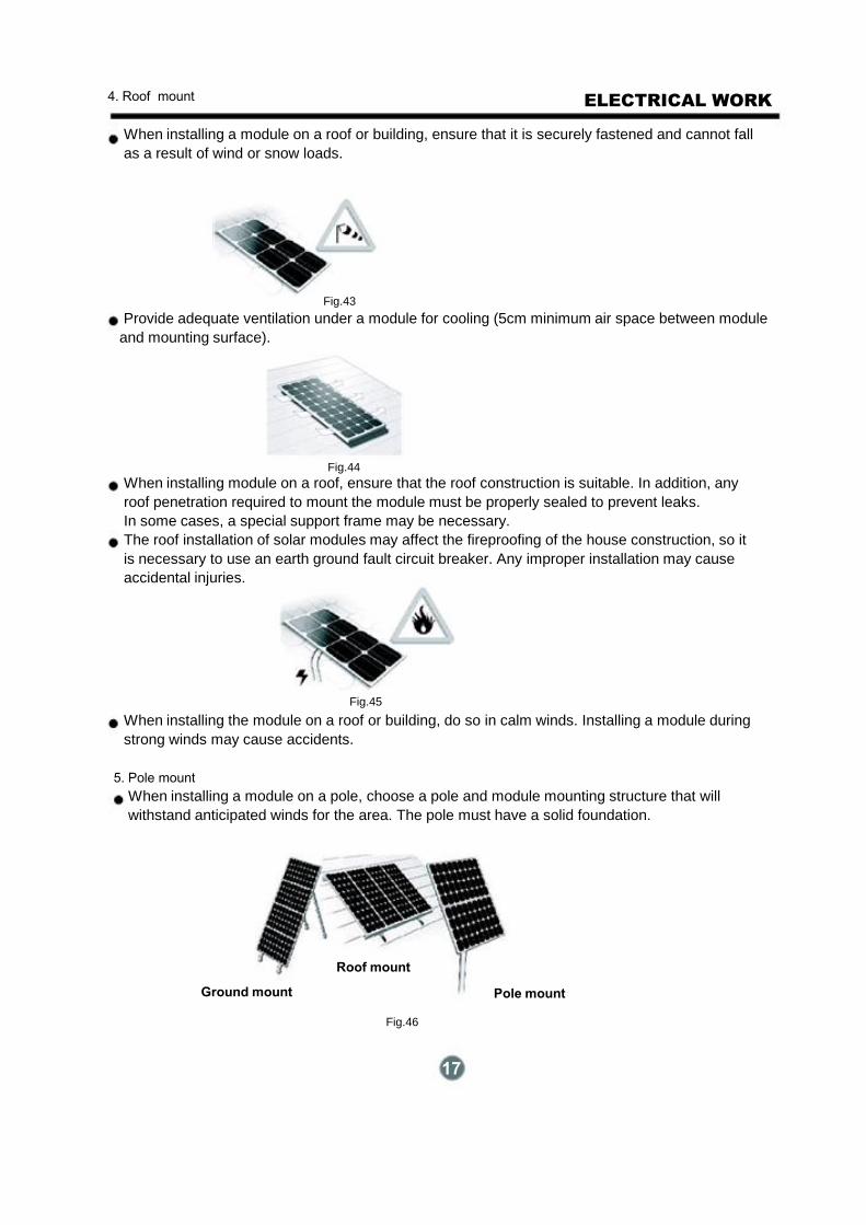
4. Roof mount
ELECTRICAL WORK
When installing a module on a roof or building, ensure that it is securely fastened and cannot fall
as a result of wind or snow loads.
Fig.43 Provide adequate ventilation under a module for cooling (5cm minimum air space between module
and mounting surface).
Fig.44 When installing module on a roof, ensure that the roof construction is suitable. In addition, any
roof penetration required to mount the module must be properly sealed to prevent leaks.
In some cases, a special support frame may be necessary.
The roof installation of solar modules may affect the fireproofing of the house construction, so it
is necessary to use an earth ground fault circuit breaker. Any improper installation may cause
accidental injuries.
Fig.45
When installing the module on a roof or building, do so in calm winds. Installing a module during
strong winds may cause accidents.
5. Pole mount When installing a module on a pole, choose a pole and module mounting structure that will
withstand anticipated winds for the area. The pole must have a solid foundation.
Roof mount
Ground mount Pole mount
Fig.46
17
ELECTRICAL WORK
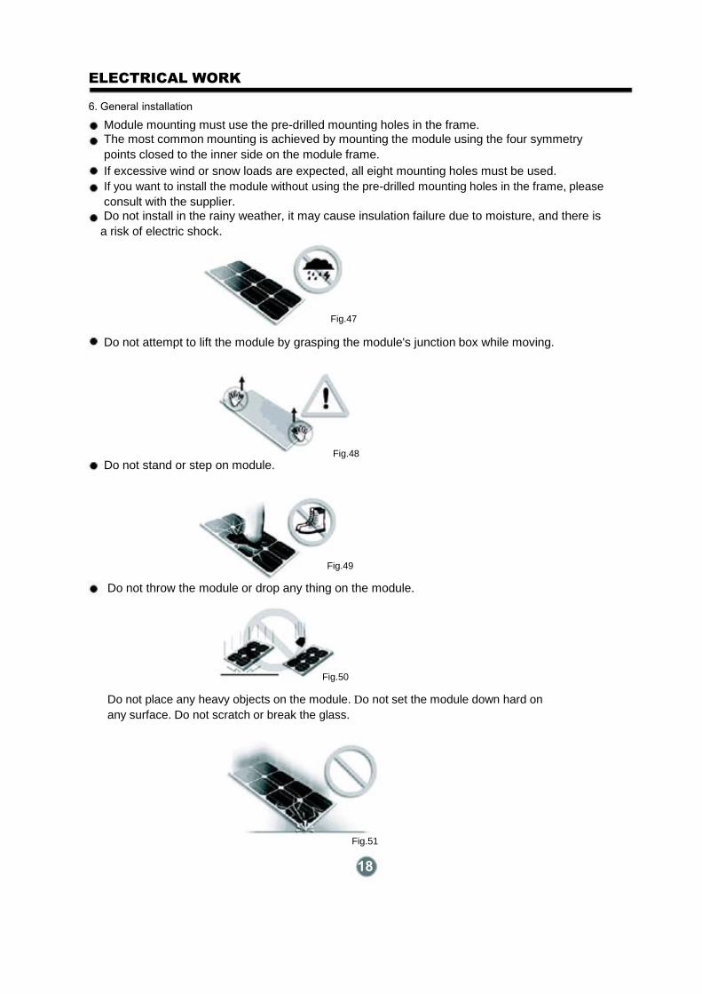
6. General installation
Module mounting must use the pre-drilled mounting holes in the frame. The most common mounting is achieved by mounting the module using the four symmetry
points closed to the inner side on the module frame.
If excessive wind or snow loads are expected, all eight mounting holes must be used. If you want to install the module without using the pre-drilled mounting holes in the frame, please consult with the supplier. Do not install in the rainy weather, it may cause insulation failure due to moisture, and there is
a risk of electric shock.
Fig.47
Do not attempt to lift the module by grasping the module's junction box while moving.
Fig.48 Do not stand or step on module.
Fig.49
Do not throw the module or drop any thing on the module.
Fig.50
Do not place any heavy objects on the module. Do not set the module down hard on
any surface. Do not scratch or break the glass.
Fig.51
18
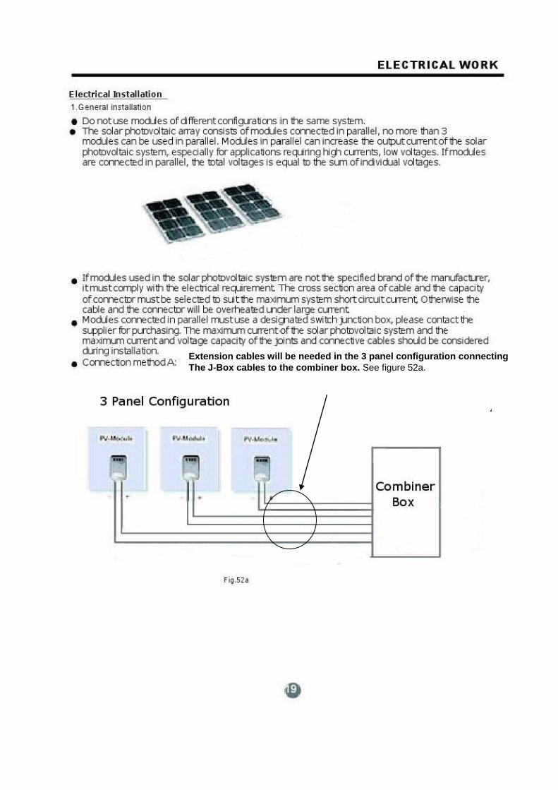
Extension cables will be needed in the 3 panel configuration connecting
The J-Box cables to the combiner box. See figure 52a.
ELECTRICAL WORK
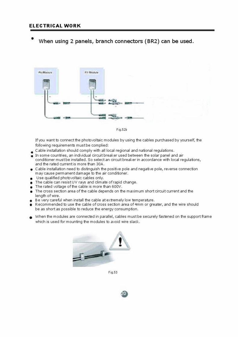
Connection method B: Using 2 panels
see Fig.52b.
Outdoor unit wire connection
Fig.52b
If you want to connect the photovoltaic modules by using the cables purchased by yourself, the
following requirements must be complied:
Cable installation should comply with all local regional and national regulations.
In some countries, an individual circuit breaker used between the solar panel and air conditioner must be installed. So select a circuit breaker in accordance with local regulations, and the rated current is more than 30A. The electrician must identify the positive pole and negative pole. Reverse connection may cause permanent damage to the air conditioner. Use qualified photovoltaic cables only. The cable can resist UV rays and climate of rapid change.
The rated voltage of the cable is more than 600V. The cross section area of the cable depends on the maximum short circuit current and the
length of wire.
Be very careful when installing the cable at extremely low temperature. Recommended to use the cable of cross section area of 4mm or greater, and the wire should be as short as possible to reduce the energy consumption. When the modules are connected in parallel, cables must be securely fastened on the support frame
which is used for mounting the modules to avoid wire slack.
Fig.53
20
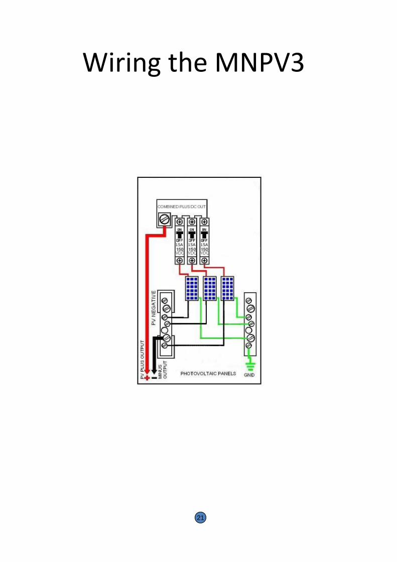
Wiring the MNPV3
21
GROUNDING PRINCIPALS
• Equipment grounding provides protection from shock caused by a ground fault and is required for all PV systems by the NEC. A ground fault occurs when a current-carrying conductor comes into contact with the frame or chassis of an appliance or an electrical box. A person who touches the frame or chassis of the faulty appliance will complete the circuit an receive a shock. The frame or chassis is deliberately wired to a grounding electrode by an equipment grounding electrode conductor. The wire dose not normally carry current except in the event of a ground fault. The grounding conductor must be continuous, connecting every non- current carrying metal part of the installation to ground. It must bond or connect to every metal electrical box, equipment chassis, and photovoltaic panel mounting. The grounding wire is never fused, switched, or interrupted in any way. When metal conduit or armored cable is used, a separate equipment ground is not usually necessary since the conduit itself acts as the continuous conductor in lieu of the grounding wire. Grounding wires are still needed to connect appliance frames to the conduit.
• Ground-fault Protection
• Roof-mounted DC PV arrays located on dwellings must be provided with DC ground-fault protection (NEC 2005, Article 690.5) Ground-fault protection isolates the grounded conductor (in DC, this is the negative wire) from ground under ground-fault conditions.
• Size of Equipment Grounding Conductor • The size of the equipment grounding wire can be as large as the current carrying
conductors, both positive and negative wires, but not smaller than specified in NEC 2005, table 250.122.
22

2 Panel Grounding
23
Liquid Tight conduit may be used between the Standard
AC Disconnect and the 30 AMP internal breaker in the
Outdoor Unit. Max 6 ft.

3 Panel Grounding
24
Liquid Tight conduit may be used between the Standard
AC Disconnect and the 30 AMP internal breaker in the
Outdoor Unit. Max 6 ft.

ELECTRICAL WORK
Do not attach the cable on the sharp edge of the frames.
Fig.54
Attention to the minimum bending radius of the wire.
Fig.55
Do not unplug the connector when the power is on.
Fig.56
The protecting sheath must be used on the cable if there is a possibility for animals or children
to touch it.
Fig.57
The manufacturer of the solar photovoltaic system can supply cables suitable for use in solar
electric systems.
25
ELECTRICAL WORK
If you want to use the connector purchased by yourself, the following requirements must be complied:
Use only connector special designed for solar electric systems.
Use the recommended or specified tools when install the connectors. Do not unplug the connectors when the power is on. The connector suitable for the solar photovoltaic system can be obtained from the manufacturer.
Electrical connection: Completely cover the module with an opaque material during mechanical installation and electrical
Installation. Protect the cables from being damaged.
Ground mounting must abide with all local regulations.
Storage battery can not be connected with the solar photovoltaic system.
Grounding: The module frame must be properly grounded. The grounding wire must be properly fastened to
the module frame to assure good electrical contact.
If the support frame is made of metal, the surface of the frame must be electroplated and have
excellent conductivity. The grounding wire must be properly fastened to the support frame .
There are two pre-drilled mounting holes in the frame, used to install the grounding cable. Each
module should connect with the grounding cable.
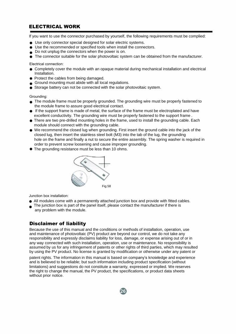
We recommend the closed lug when grounding. First insert the ground cable into the jack of the
closed lug, then insert the stainless steel bolt (M3) into the tab of the lug, the grounding
hole on the frame and finally a nut to secure the entire assembly. The spring washer is required in
order to prevent screw loosening and cause improper grounding.
The grounding resistance must be less than 10 ohms.
Fig.58
Junction box installation: All modules come with a permanently attached junction box and provide with fitted cables.
The junction box is part of the panel itself, please contact the manufacturer if there is
any problem with the module.
Disclaimer of liability
Because the use of this manual and the conditions or methods of installation, operation, use
and maintenance of photovoltaic (PV) product are beyond our control, we do not take any responsibility and expressly disclaims liability for loss, damage, or expense arising out of or in
any way connected with such installation, operation, use or maintenance. No responsibility is assumed by us for any infringement of patents or other rights of third parties, which may resulted by using the PV product. No license is granted by modification or otherwise under any patent or ,
patent rights. The information in this manual is based on company’s knowledge and experience and is believed to be reliable; but such information including product specification (without limitations) and suggestions do not constitute a warranty, expressed or implied. We reserves the right to change the manual, the PV product, the specifications, or product data sheets without prior notice.
26
EVACUATION
CAUTION
After complying to the above conditions, prepare the wiring as follows:
1) Never fail to have an individual power circuit specifically for the air conditioner. As for the method of wiring, be guided by the circuit diagram posted on the inside of control cover. 2) The screws which fasten the wiring in the electrical box are liable to come loose from vibrations which the unit is subjected to during the course of transportation. Check them and make sure that they are all tightly fastened. (If they are loose, it could cause the wires to burn out.) 3) Specification of power source. 4) Confirm that electrical capacity is sufficient. 5) Check that the starting voltage is maintained at more than 90 percent of the rated voltage marked on the nameplate. 6) Confirm that the cable thickness is as specified in the power source specification. 7) Always install a GFI circuit breaker in a wet or moist area. 8) The following could cause a voltage drop: Vibration of a magnetic switch, which will damage the contact point. Also a bad fuse or breaker
could cause a voltage drop. 9) The means for disconnection from a power supply shall be incorporated in the fixed
wiring and have an air gap contact separation of at least 3mm in each active (phase)
conductors.
Evacuation
Air and moisture in the refrigerant system have undesirable effects as indicated below:
-
Pressure in the system rises.
-
Operating current rises.
-
Cooling or heating efficiency drops.
-
Moisture in the refrigerant circuit may freeze and block capillary tubing.
-
Water may lead to corrosion of parts in the refrigeration system.
The indoor unit and tubing between the indoor and outdoor unit must be leak tested and evacuated to remove any non-condensables and moisture from the system.
Evacuation with vacuum pump - Preparation
Check that each tube (both liquid and gas side tubes) between the indoor and outdoor units have been properly connected and all wiring for the test run has been completed. Remove the service valve caps from both the gas and the liquid side on the outdoor unit. Note that both the liquid and the gas side service valves on the outdoor unit are kept closed at this stage.
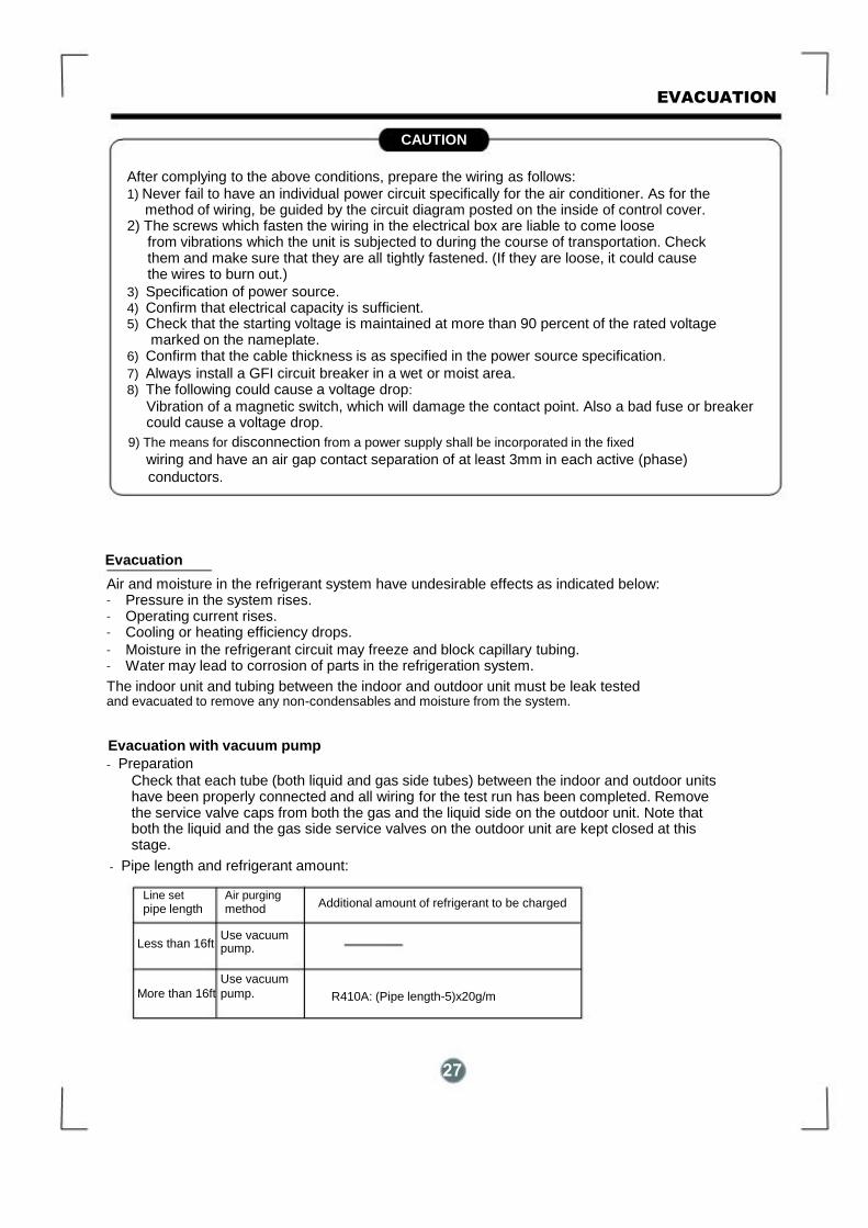
- Pipe length and refrigerant amount:
Line set Air purging
pipe length method
Additional amount of refrigerant to be charged
Less than 16ft Use vacuum pump.
Use vacuum More than 16ft pump.
R410A: (Pipe length-5)x20g/m
27
EVACUATION
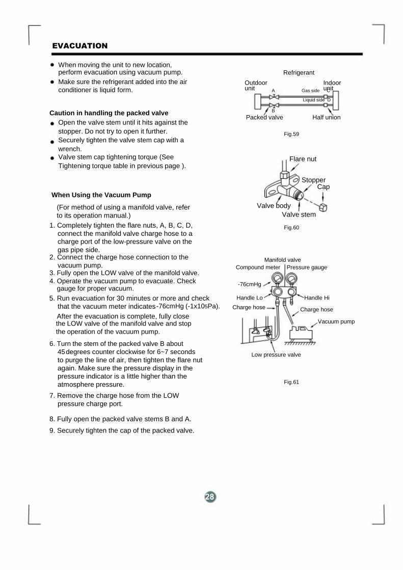
When moving the unit to new location, perform evacuation using vacuum pump. Make sure the refrigerant added into the air
conditioner is liquid form.
Caution in handling the packed valve Open the valve stem until it hits against the
stopper. Do not try to open it further.
Securely tighten the valve stem cap with a
wrench.
Valve stem cap tightening torque (See
Tightening torque table in previous page ).
When Using the Vacuum Pump
(For method of using a manifold valve, refer
to its operation manual.) 1. Completely tighten the flare nuts, A, B, C, D,
connect the manifold valve charge hose to a charge port of the low-pressure valve on the
gas pipe side. 2. Connect the charge hose connection to the
vacuum pump. 3. Fully open the LOW valve of the manifold valve. 4. Operate the vacuum pump to evacuate. Check gauge for proper vacuum.
After the evacuation is complete, fully close the LOW valve of the manifold valve and stop
the operation of the vacuum pump.
5. Run evacuation for 30 minutes or more and check
that the vacuum meter indicates
-76cmHg (-1x10⁵Pa).
6. Turn the stem of the packed valve B about
45 degrees counter clockwise for 6~7 seconds
to purge the line of air, then tighten the flare nut
again. Make sure the pressure display in the
pressure indicator is a little higher than the
atmosphere pressure. 7. Remove the charge hose from the LOW
pressure charge port. 8. Fully open the packed valve stems B and A. 9. Securely tighten the cap of the packed valve.
Refrigerant Outdoor Indoor
unit unit
A Gas side C
Liquid side D
B Packed valve Half union
Fig.59
Flare nut
Stopper Cap
Valve body Valve stem
Fig.60
Manifold valve Compound meter Pressure gauge
-76cmHg Handle Lo Handle Hi
Charge hose
Charge hose
Vacuum pump
Low pressure valve
Fig.61
28

29