Embed Size (px)
Citation preview

The Journal of Advanced Prosthodontics 207
Accuracy of a direct drill-guiding system with minimal tolerance of surgical instruments used for implant surgery: a prospective clinical study
Du-Hyeong Lee1, Seo-Young An2, Min-Ho Hong3, Kyoung-Bae Jeon4, Kyu-Bok Lee1* 1Department of Prosthodontics, School of Dentistry, A3DI, Kyungpook National University, Daegu, Republic of Korea2Department of Oral and Maxillofacial Radiology, School of Dentistry, Kyungpook National University, Daegu, Republic of Korea3Department of Bio-medical Research Institute, A3DI, Kyungpook National University Hospital, Daegu, Republic of Korea4Department of Prosthodontics, School of Dentistry, Kyungpook National University, Daegu, Republic of Korea
PURPOSE. A recently introduced direct drill-guiding implant surgery system features minimal tolerance of surgical instruments in the metal sleeve by using shank-modified drills and a sleeve-incorporated stereolithographic guide template. The purpose of this study was to evaluate the accuracy of this new guided surgery system in partially edentulous patients using geometric analyses. MATERIALS AND METHODS. For the study, 21 implants were placed in 11 consecutive patients using the direct drill-guiding implant surgery system. The stereolithographic surgical guide was fabricated using cone-beam computed tomography, digital scanning, computer-aided design and computer-assisted manufacturing, and additive manufacturing processes. After surgery, the positional and angular deviations between planned and placed implants were measured at the abutment level using implant-planning software. The Kruskal-Wallis test and Mann-Whitney U test were used to compare the deviations (α=.05). RESULTS. The mean horizontal deviations were 0.593 mm (SD 0.238) mesiodistally and 0.691 mm (SD 0.344) buccolingually. The mean vertical deviation was 0.925 mm (SD 0.376) occlusogingivally. The vertical deviation was significantly larger than the horizontal deviation (P=.018). The mean angular deviation was 2.024 degrees (SD 0.942) mesiodistally and 2.390 degrees (SD 1.142) buccolingually. CONCLUSION. The direct drill-guiding implant surgery system demonstrates high accuracy in placing implants. Use of the drill shank as the guiding component is an effective way for reducing tolerance. [ J Adv Prosthodont 2016;8:207-13]
KEY WORDS: Accuracy; Guided surgery; Dental implants; Tolerance; Surgical drills
http://dx.doi.org/10.4047/jap.2016.8.3.207http://jap.or.kr J Adv Prosthodont 2016;8:207-13
INTRODUCTION
Appropriate placement of dental implants is essential for esthetic and restorative aspects.1,2 The development of computer-assisted guided surgery has helped realize resto-ration-driven implant placement.3 Contemporary guided implant surgery systems are generally based on cone-beam computed tomography (CBCT) and computer-aided design and computer-assisted manufacturing (CAD/CAM) tech-nologies. CBCT visualizes anatomic structures without superimposition, which enables 3-dimensional (3D) diagno-sis and treatment planning.4-6 CAD/CAM technologies improve the fabrication of surgical guides by reducing man-ual work and facilitating transfer of the planned implant position to the guide template.7 Accurate placement of implants makes it possible to deliver restorations to the
Corresponding author: Kyu-Bok LeeDepartment of Prosthodontics, School of Dentistry, A3DI, Kyungpook National University, 2175 Dalgubeoldae-ro, Jung-gu, Daegu 41904, Republic of KoreaTel. 82536007674: e-mail, [email protected] November 17, 2015 / Last Revision January 26, 2016 / Accepted April 26, 2016
© 2016 The Korean Academy of ProsthodonticsThis is an Open Access article distributed under the terms of the Creative Commons Attribution Non-Commercial License (http://creativecommons.org/licenses/by-nc/3.0) which permits unrestricted non-commercial use, distribution, and reproduction in any medium, provided the original work is properly cited.
pISSN 2005-7806, eISSN 2005-7814
This work was supported by the ministry of trade, industry and energy of the Republic of Korea and Daegyeong institute for regional program evaluation and Daegu technopark (Greater economies leading industry promotion project)

208
patient’s mouth on the day of the surgery.8,9 Accordingly, these advancements have optimized implant treatment to be more predictable, less invasive, and faster from both a surgical and a prosthodontic point of view.10,11
Surgical guide templates are categorized based on the extent of drilling restriction.12 Nonlimiting design is sim-plistic; although such guides serve as imaging indicators for marking the entry point of drilling, they do not limit the angulation or the depth of drilling motion. Thus, nonlimit-ing design may result in inaccurate implant angulations. Partially limiting design incorporates a component restrict-ing the initial drill used for osteotomy. However, in general, hole enlargement and implant placement are still performed freehand by the surgeon. Most surgical guides with partially limiting design are converted from a radiographic template that is used to evaluate the surgical bone site and devise a surgery plan. Completely limiting design is the most advanced type of guide, restricting the drilling process and placement of implant in three dimensions. This design con-cept reduces the need for decision making during surgery, thereby leading to more predictable results of implant placement. Contemporary CAD/CAM-based surgical guides are included in this category.13,14
The accuracy of a guided implant surgery system is defined as the deviation between the planned and placed position of the implant.15 The accuracy of the entire proce-dure is a quantitative evaluation of positional and angular discrepancies in 3D coordinates.16 The measurements are performed using image superimposition of pre- and post-operative CT images.17 Possible sources of error include factors such as digitizing, superimposition, machining pro-cess, the guide design concept, and the operator’s experi-ence.18,19 In a recent in vitro study, Van Assche and Quirynen reported a noticeable tolerance of surgical implant instru-ments within the metal sleeve.15 This tolerance is caused by the gap between the drill and the guide sleeve, which allows rotation of the drill in the sleeve. Unwanted lateral osteoto-my may occur when the drill is not parallel to the sleeve during the drilling; therefore, this type of error is defined as an intrinsic error.20 On the other hand, if there is no toler-ance, the friction generated from mechanical components hinders the drilling process, which might result in sleeve deformation.
Recently, a direct drill-guiding implant surgery system with a completely limiting design was developed. This sys-tem features shank-modified drills that use the shank por-tion of surgical instruments as a guiding component to lim-it drilling motion with little tolerance. Moreover, a guide sleeve is incorporated in the stereolithographic surgical guide design, which eliminates the need for additional inser-tion of metal guide sleeves into the guide template. The purpose of this study was to investigate the accuracy of this newly developed guided implant surgery system in par-tially edentulous patients using prospective clinical design and geometric analyses.21,22
MATERIALS AND METHODS
Eleven patients (5 men, 6 women; aged 21-75 years; mean age 46 years) requiring implant placements in partially eden-tulous jaws were included in this study. All patients were treated at the same prosthodontics department of a univer-sity hospital. A total of 21 implants (AnyOne; MegaGen Implant, Gyeongbuk, Korea) were placed. 9 implants were inserted in the maxilla, and 12 in the mandible. Patients with a history of debilitating systemic disease or requiring ridge augmentation with bone grafting were excluded from the study. The study was approved by the Institutional Review Board of the hospital (2014-11-020).
A conventional impression was taken, and a stone cast was fabricated for each patient. The surface image of the cast was then digitized into surface tessellation language (STL) format using a desktop scanner (Ceramill Map 400; Amann Girrbach, Koblach, Austria). Images of the under-lying bone were obtained using a CBCT scanner (PaX-Flex3D; Vatech Co., Hwasung, Korea) with a field of view of 120 × 85 mm, voxel size of 0.2 mm, and exposure con-ditions of 90 kVp, 10 mA, and 24-second pulsed scan. During CBCT image taking, patients were directed to bite a radiopaque Datum tray (MegaGen Implant, Gyeongbuk, Korea) in centric occlusion. The CBCT data were saved in digital imaging and communications in medicine (DICOM) format. The Datum tray was also digitized into a STL file using the desktop scanner (Ceramill Map 400; Amann Girrbach, Koblach, Austria). The solid block portion of the Datum tray was used as a medium for superimposition of the surface image and underlying bone image. The DICOM file and the two STL files were imported into an implant-planning software program (R2GATE 1.0; MegaGen Implant, Gyeongbuk, Korea) where the image merging and virtual surgery were performed. The image-merging pro-cess was performed with manual registration by selecting three anatomic landmarks from the dentition. The position of the implant was determined based on the underlying bone and virtual restoration (Fig. 1). After surgery planning, a surgical guide was designed (Fig. 2) and fabricated using a 3D printer (Perfactory 4 DDP; EnvisionTEC, Dearborn, MI, USA).
The direct drill-guiding system in this study uses shank-modified drills whose structure has 3 parts: the stopper part, the guide part, and the drilling part (Fig. 3). The stop-per structure of the drill corresponds with the stepped structure of the internal surface of the sleeve and restricts the drilling depth when the two structures are joined. The guide part of the drill closely accommodates the sleeve of the guide, which limits the orientation of the drilling motion. The guide part of the drill has the uniform diame-ter and length; this feature eliminates the need for addition-al internal tubes. The handpiece connector and ratchet con-nector are instruments for inserting the implant fixture after osteotomy. As the component for depth control, the handpiece connector has the stopper structure, and the ratchet connector has a horizontal marking to indicate the
J Adv Prosthodont 2016;8:207-13

The Journal of Advanced Prosthodontics 209
correct depth of insertion. The sleeve structure of this sys-tem is incorporated into the design of the guide template, so the guiding component is created together with the guide body when the template is fabricated (Fig. 4).
Implant surgery was performed according to the manu-facturers’ instructions. All patients underwent flapless sur-gery under local anesthesia with 2% lidocaine. The printed surgical guide was placed over the corresponding edentu-lous area and adjacent teeth. Implant osteotomy was per-formed using shank-modified drills (Fig. 5A). Each drilling was performed until the stopper of the drill contacted the rim of the guide template. The implant fixture was inserted using the ratchet (Fig. 5B). All implants were placed by a single operator. To obtain the positional information of the placed implant, postoperative CBCT scanning was conduct-ed using the same settings as the preoperative scan.
fig. 1. Implant treatment planning. (A) cross-sectional image of virtually placed implant, (B) three-dimensional image of virtual restorations.
A B
fig. 2. Designing the surgical guide.
fig. 3. Surgical instruments used in the direct drill-guiding system (R2GATE). Left to right: initial drill, stop drill, handpiece connector, ratchet connector (a: stopper part, b: guide part, c: drilling part).
fig. 4. Guide sleeve component of the guide template. The stepped structure of the sleeve restricts the depth of drilling by corresponding with the stopper of the drill.
Accuracy of a direct drill-guiding system with minimal tolerance of surgical instruments used for implant surgery: a prospective clinical study

210
The accuracy of the guided surgery system was evaluat-ed at the abutment level by comparing the virtual abut-ments of the planned and placed implants (Fig. 6). The planned position of the abutment was determined by the planned position of implant. The actual position of the abutment was determined based on the actual position of the implant in the postoperative CBCT scan. The outcome parameters were horizontal deviation, vertical deviation, and angular deviation, and the values were calculated using the centerlines of the abutments and reference points in 3 dimensions.
All data were reported as the mean ± standard deviation and visualized via bar graphs. The Kruskal-Wallis test and Mann-Whitney U test were used to compare the amounts of deviation among 3 planes. Statistical analyses were per-formed using SPSS 22.0 for Windows (SPSS Inc., Chicago, IL, USA). A P value < .05 was considered significant.
RESULTS
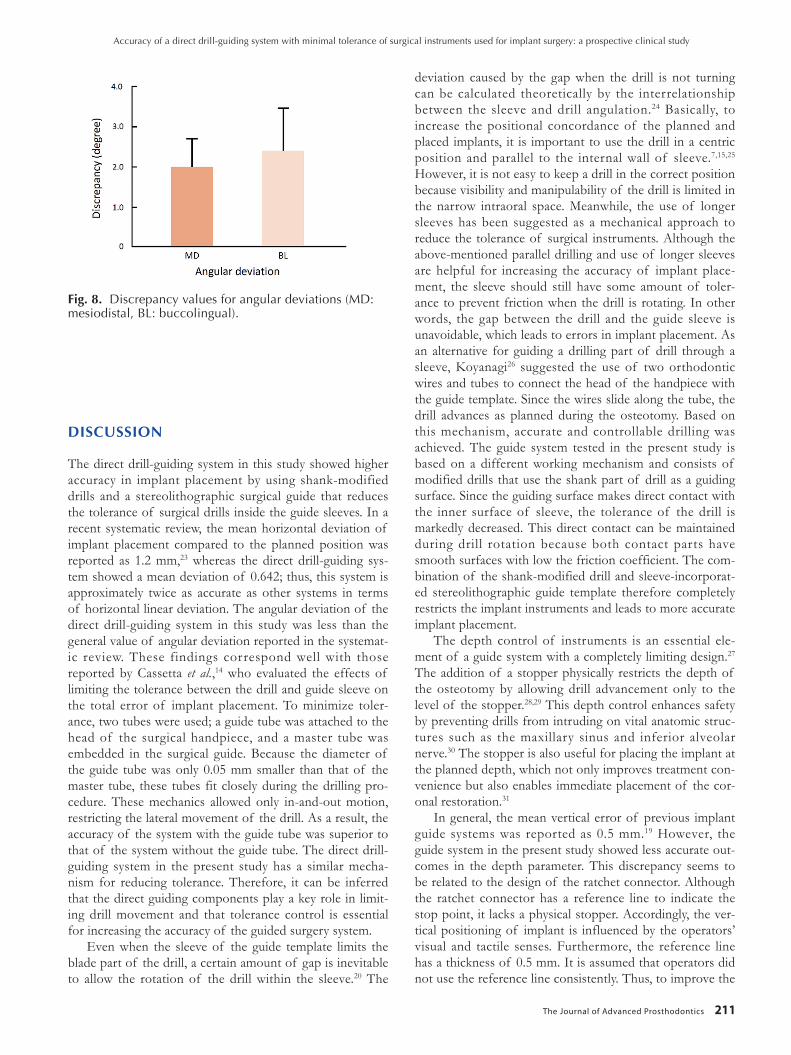
Fig. 7 shows positional deviations between planned and actual abutments. The means and standard deviations of horizontal deviation were 0.593 ± 0.238 mm in the mesio-distal direction and 0.691 ± 0.344 mm in the buccolingual direction. The mean vertical deviation was 0.925 ± 0.376 mm in the occlusogingival direction, which was significantly larger than the horizontal deviations (P = .018). However, there was no significant difference between the two hori-zontal deviations (P = .421). As for angular deviation, the values were 2.024 ± 0.942 degrees in the mesiodistal direc-tion and 2.390 ± 1.142 degrees in the buccolingual direc-tion (Fig. 8), but the difference was not significant (P = .308).
fig. 5. (A) Implant osteotomy using shank-modified drills, (B) Implant placement using the ratchet and ratchet connector.
A B
fig. 6. Definition of measurement parameters (A: horizontal deviation, B: vertical deviation, and C: angular deviation).
fig. 7. Discrepancy values for horizontal and vertical deviations in three dimensions (MD: mesiodistal, BL: buccolingual, OG: occlusogingival. *Significant difference).
J Adv Prosthodont 2016;8:207-13
The Journal of Advanced Prosthodontics 211
DISCUSSION
The direct drill-guiding system in this study showed higher accuracy in implant placement by using shank-modified drills and a stereolithographic surgical guide that reduces the tolerance of surgical drills inside the guide sleeves. In a recent systematic review, the mean horizontal deviation of implant placement compared to the planned position was reported as 1.2 mm,23 whereas the direct drill-guiding sys-tem showed a mean deviation of 0.642; thus, this system is approximately twice as accurate as other systems in terms of horizontal linear deviation. The angular deviation of the direct drill-guiding system in this study was less than the general value of angular deviation reported in the systemat-ic review. These findings correspond well with those reported by Cassetta et al.,14 who evaluated the effects of limiting the tolerance between the drill and guide sleeve on the total error of implant placement. To minimize toler-ance, two tubes were used; a guide tube was attached to the head of the surgical handpiece, and a master tube was embedded in the surgical guide. Because the diameter of the guide tube was only 0.05 mm smaller than that of the master tube, these tubes fit closely during the drilling pro-cedure. These mechanics allowed only in-and-out motion, restricting the lateral movement of the drill. As a result, the accuracy of the system with the guide tube was superior to that of the system without the guide tube. The direct drill-guiding system in the present study has a similar mecha-nism for reducing tolerance. Therefore, it can be inferred that the direct guiding components play a key role in limit-ing drill movement and that tolerance control is essential for increasing the accuracy of the guided surgery system.
Even when the sleeve of the guide template limits the blade part of the drill, a certain amount of gap is inevitable to allow the rotation of the drill within the sleeve.20 The
deviation caused by the gap when the drill is not turning can be calculated theoretically by the interrelationship between the sleeve and drill angulation.24 Basically, to increase the positional concordance of the planned and placed implants, it is important to use the drill in a centric position and parallel to the internal wall of sleeve.7,15,25 However, it is not easy to keep a drill in the correct position because visibility and manipulability of the drill is limited in the narrow intraoral space. Meanwhile, the use of longer sleeves has been suggested as a mechanical approach to reduce the tolerance of surgical instruments. Although the above-mentioned parallel drilling and use of longer sleeves are helpful for increasing the accuracy of implant place-ment, the sleeve should still have some amount of toler-ance to prevent friction when the drill is rotating. In other words, the gap between the drill and the guide sleeve is unavoidable, which leads to errors in implant placement. As an alternative for guiding a drilling part of drill through a sleeve, Koyanagi26 suggested the use of two orthodontic wires and tubes to connect the head of the handpiece with the guide template. Since the wires slide along the tube, the drill advances as planned during the osteotomy. Based on this mechanism, accurate and controllable drilling was achieved. The guide system tested in the present study is based on a different working mechanism and consists of modified drills that use the shank part of drill as a guiding surface. Since the guiding surface makes direct contact with the inner surface of sleeve, the tolerance of the drill is markedly decreased. This direct contact can be maintained during drill rotation because both contact parts have smooth surfaces with low the friction coefficient. The com-bination of the shank-modified drill and sleeve-incorporat-ed stereolithographic guide template therefore completely restricts the implant instruments and leads to more accurate implant placement.
The depth control of instruments is an essential ele-ment of a guide system with a completely limiting design.27 The addition of a stopper physically restricts the depth of the osteotomy by allowing drill advancement only to the level of the stopper.28,29 This depth control enhances safety by preventing drills from intruding on vital anatomic struc-tures such as the maxillary sinus and inferior alveolar nerve.30 The stopper is also useful for placing the implant at the planned depth, which not only improves treatment con-venience but also enables immediate placement of the cor-onal restoration.31
In general, the mean vertical error of previous implant guide systems was reported as 0.5 mm.19 However, the guide system in the present study showed less accurate out-comes in the depth parameter. This discrepancy seems to be related to the design of the ratchet connector. Although the ratchet connector has a reference line to indicate the stop point, it lacks a physical stopper. Accordingly, the ver-tical positioning of implant is influenced by the operators’ visual and tactile senses. Furthermore, the reference line has a thickness of 0.5 mm. It is assumed that operators did not use the reference line consistently. Thus, to improve the
fig. 8. Discrepancy values for angular deviations (MD: mesiodistal, BL: buccolingual).
Accuracy of a direct drill-guiding system with minimal tolerance of surgical instruments used for implant surgery: a prospective clinical study
212
accuracy of this system in the vertical dimension, inclusion of a stopper structure on the ratchet connector is recom-mended.
The accuracy of guided implant surgery is influenced by procedures that transfer the digital virtual plan to the surgi-cal site.19 Possible individual errors originate from intrinsic sources, which include issues with radiography quality, file conversion, CAD software, and the tolerance between mechanical components; and extrinsic sources, which relate to the fit of surgical guide, the mucosal thickness at the sur-gical site, the position of the edentulous area, and the sur-geon’s experience. The accumulation of individual errors produces the total deviation between planned and postop-erative outcomes. This study revealed the error in the accu-racy of the newly developed guided implant surgery system. Since the data were obtained from clinical cases, the out-come values are clinically valid and meaningful. However, this study did not assess the effects of individual error sources. Thus, controlled in vitro experiments or large-size clinical prospective trials will be needed in the future to analyze these effects.
CONCLUSION
To our knowledge, this is the first clinical report to evaluate the accuracy of a direct drill-guiding system for implant placement. The present study confirms that the use of shank-modified drills and sleeve-incorporated stereolitho-graphic templates is an effective way to improve the accura-cy of implant placement by minimizing mechanical toler-ance of the instruments.
ORCID
Du-Hyeong Lee http://orcid.org/0000-0003-2803-7457Seo-Young An http://orcid.org/0000-0001-6711-5986Min-Ho Hong http://orcid.org/0000-0002-6456-2200Kyoung-Bae Jeon http://orcid.org/0000-0002-5289-4179Kyu-Bok Lee http://orcid.org/0000-0002-1838-7229
REfERENCES
1. Garber DA, Belser UC. Restoration-driven implant place-ment with restoration-generated site development. Compend Contin Educ Dent 1995;16:796, 798-802, 804.
2. Becker CM, Kaiser DA. Surgical guide for dental implant placement. J Prosthet Dent 2000;83:248-51.
3. D’Souza KM, Aras MA. Types of implant surgical guides in dentistry: a review. J Oral Implantol 2012;38:643-52.
4. Marchack CB. CAD/CAM-guided implant surgery and fabri-cation of an immediately loaded prosthesis for a partially edentulous patient. J Prosthet Dent 2007;97:389-94.
5. Park C, Raigrodski AJ, Rosen J, Spiekerman C, London RM. Accuracy of implant placement using precision surgical guides with varying occlusogingival heights: an in vitro study. J Prosthet Dent 2009;101:372-81.
6. Lee SL, Kim HJ, Son MK, Chung CH. Anthropometric anal-
ysis of maxillary anterior buccal bone of Korean adults using cone-beam CT. J Adv Prosthodont 2010;2:92-6.
7. Koop R, Vercruyssen M, Vermeulen K, Quirynen M. Tolerance within the sleeve inserts of different surgical guides for guid-ed implant surgery. Clin Oral Implants Res 2013;24:630-4.
8. Aalam AA, Nowzari H, Krivitsky A. Functional restoration of implants on the day of surgical placement in the fully edentulous mandible: a case series. Clin Implant Dent Relat Res 2005;7:10-6.
9. Barone A, Rispoli L, Vozza I, Quaranta A, Covani U. Immediate restoration of single implants placed immediately after tooth extraction. J Periodontol 2006;77:1914-20.
10. Holst S, Blatz MB, Eitner S. Precision for computer-guided implant placement: using 3D planning software and fixed in-traoral reference points. J Oral Maxillofac Surg 2007;65:393-9.
11. Youk SY, Lee JH, Park JM, Heo SJ, Roh HK, Park EJ, Shin IH. A survey of the satisfaction of patients who have under-gone implant surgery with and without employing a comput-er-guided implant surgical template. J Adv Prosthodont 2014; 6:395-405.
12. Stumpel LJ 3rd. Cast-based guided implant placement: a nov-el technique. J Prosthet Dent 2008;100:61-9.
13. Noharet R, Pettersson A, Bourgeois D. Accuracy of implant placement in the posterior maxilla as related to 2 types of surgical guides: a pilot study in the human cadaver. J Prosthet Dent 2014;112:526-32.
14. Cassetta M, Di Mambro A, Di Giorgio G, Stefanelli LV, Barbato E. The Influence of the Tolerance between Mechanical Components on the Accuracy of Implants Inserted with a Stereolithographic Surgical Guide: A Retrospective Clinical Study. Clin Implant Dent Relat Res 2015;17:580-8.
15. Van Assche N, Quirynen M. Tolerance within a surgical guide. Clin Oral Implants Res 2010;21:455-8.
16. Widmann G, Bale RJ. Accuracy in computer-aided implant surgery-a review. Int J Oral Maxillofac Implants 2006;21:305-13.
17. D’haese J, Van De Velde T, Elaut L, De Bruyn H. A prospec-tive study on the accuracy of mucosally supported stereo-lithographic surgical guides in fully edentulous maxillae. Clin Implant Dent Relat Res 2012;14:293-303.
18. Block MS, Chandler C. Computed tomography-guided sur-gery: complications associated with scanning, processing, sur-gery, and prosthetics. J Oral Maxillofac Surg 2009;67:13-22.
19. Vercruyssen M, Hultin M, Van Assche N, Svensson K, Naert I, Quirynen M. Guided surgery: accuracy and efficacy. Periodontol 2000 2014;66:228-46.
20. Cassetta M, Di Mambro A, Giansanti M, Stefanelli LV, Cavallini C. The intrinsic error of a stereolithographic surgi-cal template in implant guided surgery. Int J Oral Maxillofac Surg 2013;42:264-75.
21. Verhamme LM, Meijer GJ, Boumans T, de Haan AF, Bergé SJ, Maal TJ. A clinically relevant accuracy study of computer-planned implant placement in the edentulous maxilla using mucosa-supported surgical templates. Clin Implant Dent Relat Res 2015;17:343-52.
22. Van de Wiele G, Teughels W, Vercruyssen M, Coucke W,
J Adv Prosthodont 2016;8:207-13

The Journal of Advanced Prosthodontics 213
Temmerman A, Quirynen M. The accuracy of guided sur-gery via mucosa-supported stereolithographic surgical tem-plates in the hands of surgeons with little experience. Clin Oral Implants Res 2015;26:1489-94.
23. Van Assche N, Vercruyssen M, Coucke W, Teughels W, Jacobs R, Quirynen M. Accuracy of computer-aided implant placement. Clin Oral Implants Res 2012;23:112-23.
24. Verhamme LM, Meijer GJ, Boumans T, Schutyser F, Bergé SJ, Maal TJ. A clinically relevant validation method for im-plant placement after virtual planning. Clin Oral Implants Res 2013;24:1265-72.
25. Lee JH, Park JM, Kim SM, Kim MJ, Lee JH, Kim MJ. An as-sessment of template-guided implant surgery in terms of ac-curacy and related factors. J Adv Prosthodont 2013;5:440-7.
26. Koyanagi K. Development and clinical application of a surgi-cal guide for optimal implant placement. J Prosthet Dent 2002;88:548-52.
27. De Kok IJ, Thalji G, Bryington M, Cooper LF. Radiographic stents: integrating treatment planning and implant placement. Dent Clin North Am 2014;58:181-92.
28. Greenstein G, Greenstein B, Desai RN. Using drill stops on twist drills to promote safety and efficiency when creating os-teotomies for dental implants. J Am Dent Assoc 2014;145: 371-5.
29. Schwarz L, Pommer B, Bijak M, Watzek G, Unger E. Auto-stop drilling device for implant site preparation: in vitro test of eccentric sensor position. Int J Oral Maxillofac Implants 2015;30:1041-6.
30. Juodzbalys G, Wang HL, Sabalys G, Sidlauskas A, Galindo-Moreno P. Inferior alveolar nerve injury associated with im-plant surgery. Clin Oral Implants Res 2013;24:183-90.
31. Nelogi S, Rao BS, Naveen HC, Porwal A, Nelogi M. A surgi-cal guide for optimal placement and immediate restoration of implant. J Oral Implantol 2014;40:623-6.
Accuracy of a direct drill-guiding system with minimal tolerance of surgical instruments used for implant surgery: a prospective clinical study