Embed Size (px)
Citation preview

INSTALLATION GUIDE AND OWNER’S MANUAL
AccuMix II™
ELECTRIC INSTANTANEOUS WATER HEATER WITH ASSE 1070 APPROVED MIXING VALVE

2

3
BEFORE ATTEMPTING ANY INSTALLATION, MODIFICATION OR SERVICE OF THIS HEATER, MAKE SURE THE ELECTRICAL POWER IS DISCONNECTED.
Read and understand these instructions thoroughly before attempting the installation or service of this water heater. Failure to follow these instructions can result in serious injury, death and/or property damage. The warranty of this water heater will depend upon proper installation according to these instructions. Some heaters come supplied with separate faucet aerators. If supplied, the aerator must be installed in the faucet for optimum performance. This heater must be used to heat water only and must be installed in a location where it is not subject to freezing temperatures. The manufacturer is not liable for any damages resulting from improper installation or misuse.
This installation must conform to the latest requirements of the National Electrical Code and all applicable state and local codes. This information is available through your local authorities. You must understand these requirements before beginning this installation.
This unit is not required by UL 499 to employ a temperature and pressure relief valve (T&P). You should check with local codes to find out if one is required. If it is, it must be installed in the outlet hot water pipe between the heater and the isolation valve.
IMPORTANT SAFETY INSTRUCTIONS
When using this electrical equipment, basic safety precautions should always be followed, including the following:
READ AND FOLLOW ALL INSTRUCTIONS
A green terminal (or a wire connector marked “G”, “GR, “Ground”, or “GROUNDING”) is provided within the control box. To reduce the risk of electric shock, connect this terminal or connector to the grounding terminal of the electric service or supply panel with a continuous copper wire in accordance with your local electrical code.
Contents
GENERAL .....................................................................................................................................................................4 1) MOUNTING THE UNIT TO THE WALL......................................................................................................................5 2) PLUMBING HOOK-UP .............................................................................................................................................6 3) ELECTRICAL HOOK-UP ............................................................................................................................................9 4) COMMISSIONING THE HEATER ........................................................................................................................... 11 5) TROUBLESHOOTING ............................................................................................................................................ 13 6) PERIODIC MAINTENANCE .................................................................................................................................... 14 7) PART NUMBERS FOR FITTINGS, AERATORS AND AERATOR ADAPTORS ............................................................. 15 8) REPAIR PARTS FOR ACCUMIX II UNITS ................................................................................................................ 15

4
(CANADIAN INSTALLATIONS ONLY) CONNECT ONLY TO A CIRCUIT PROTECTED BY A CLASS A GROUND FAULT CIRCUIT INTERRUPTER. ATTENTION: BRANCHER UNIQUEMENT
À UN CIRCUIT PROTÉGÉ PAR UN DISJONCTEUR DE FUITE DE TERRE DE CLASSE A. (CANADIAN INSTALLATIONS ONLY) DO NOT INSTALL IN A BATH ENCLOSURE OR SHOWER STALL OR CONNECT TO A SALT-REGENERATED WATER SOFTENER OR A
WATER SUPPLY OF SALT WATER. ATTENTION: NE PAS INSTALLER DANS UNE BAIGNOIRE OU UNE CABINE DE DOUCHE ET NE PAS BRANCHER À UN ADOUCISSEUR D’EAU RÉGÉNÉRÉ AVEC DU SEL OU À UN APPROVISIONNEMENT EN EAU SALÉE.
(CANADIAN INSTALLATIONS ONLY) USE COPPER CONDUCTORS ONLY. USE BONDING CONDUCTOR IN ACCORDANCE WITH THE CANADIAN ELECTRICAL CODE PART I. UTILISEZ
DEZ CONDUCTEURS EN CUIVE UNIQUEMENT. UTILISEZ DES CONDUCTEURS DE MIZE À LA MASSE CONFORMEMENT AU CODE CANADIEN DE L’ÉLECTRICITÉ, PARTIE I.
SAVE THESE INSTRUCTIONS
GENERAL
The Eemax, Inc.™ AccuMix II heater is specifically designed to take in cold water and heat it to temperatures suitable for handwashing and other mild temperature uses up to a factory preset of 105°F. The unit employs a complex algorithm that actively manages power application to real-time system demand. An integrated flow meter, along with inlet and outlet thermistors, provide data that allows the heater to instantly adapt to variations in flow and temperature. It is also equipped with an ASSE 1070-2004 approved mixing valve to meet UPC 407.3 and similar plumbing codes for public handwashing applications. AccuMix II employs an integrated mixing valve utilized according to the manufacturer’s stated specifications and certified to ASSE 1070-2004.
To obtain optimum performance and energy savings, the unit should be located as close as possible to the point-of-use. The unit is supplied with compression rings and nuts suitable for direct coupling to 3/8” copper or PEX™ piping. Do not use additional screwed fittings, pipe dope or teflon tape – doing so will void the warranty. DO NOT SOLDER PIPES WHILE THE UNIT IS INSTALLED as serious damage to the heater will result.

5
1) MOUNTING THE UNIT TO THE WALL
THIS HEATER MUST BE INSTALLED IN A LOCATION WHERE IT IS NOT SUBJECT TO FREEZING TEMPERATURES.
1. The heater should be mounted under the sink as close to the point-of-use as possible. Ideal position is
fittings pointed down, but the heater can be mounted in any orientation.
2. Make sure to leave a minimum of 8 inches service clearance at the end OPPOSITE the fittings.
3. Remove the cover and fasten to the wall using the four mounting holes at each corner of the back plate. Replace the cover.

6
2) PLUMBING HOOK-UP
The heater is supplied with 3/8”brass compression fittings that are compatible with either copper or plastic pipes. Make sure these fittings are used for this installation. Contact your Eemax representative for further information.
Eemax strongly recommends that the heater be supplied directly from the main cold water trunk line when possible. This helps to avoid a potential water flow interruption to the heater which could lead to a failure of the heating element.
System Requirements:
• Minimum/maximum working pressure: 30 PSI/150 PSI • Optimal operating pressure range: 35 to 80 PSI • Min flow rate 0.3 GPM
For optimum performance, we recommend the use of isolation valves (full flow ball type) on the inlet and outlet pipes and use of a 40 mesh Y-Strainer on the inlet of the heater. Clean screen periodically for best performance of the mixing valve.
BEFORE ATTEMPTING ANY INSTALLATION, MODIFICATION OR SERVICE OF THIS HEATER, MAKE SURE THE ELECTRICAL POWER IS DISCONNECTED.
NEVER SUBSTITUTE THREADED PIPE FITTINGS USING PIPE DOPE OR TEFLON TAPE AND NEVER SOLDER ANY PIPE CONNECTIONS WHILE ATTACHED TO THIS HEATER BECAUSE
DAMAGE TO THE HEATER WILL RESULT. DOING THIS WILL VOID THE WARRANTY!
1. The heater’s water INLET and OUTLET are labeled.
Install full flow ball valves to the inlet and outlet pipes and run water through the inlet pipe into a bucket to purge it of any debris. Close the inlet ball valve. FAILURE TO DO SO MAY CLOG MIXING VALVE!
2. Make sure the inlet filter screen is present in the inlet fitting and the inlet and outlet pipes are correctly aligned with the heater connections to minimize stress on the heater.
7
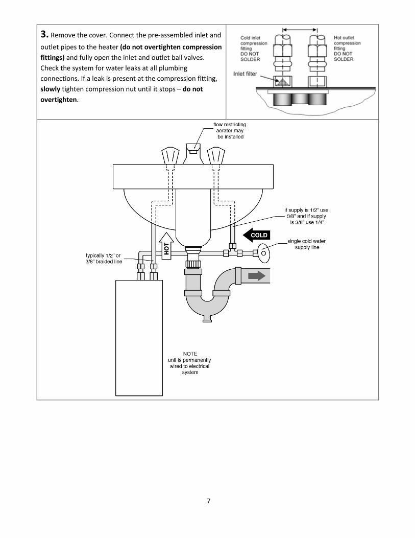
3. Remove the cover. Connect the pre-assembled inlet and
outlet pipes to the heater (do not overtighten compression fittings) and fully open the inlet and outlet ball valves. Check the system for water leaks at all plumbing connections. If a leak is present at the compression fitting, slowly tighten compression nut until it stops – do not overtighten.
8
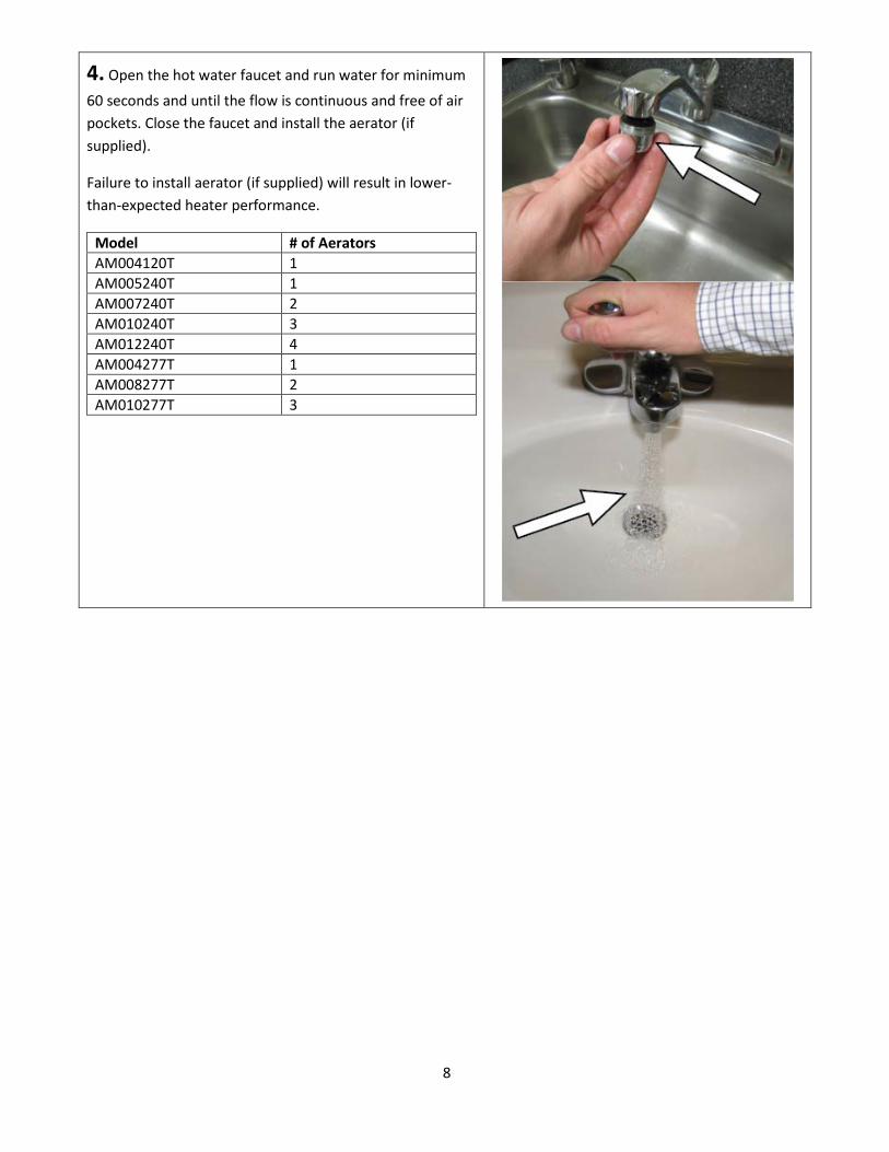
4. Open the hot water faucet and run water for minimum
60 seconds and until the flow is continuous and free of air pockets. Close the faucet and install the aerator (if supplied).
Failure to install aerator (if supplied) will result in lower-than-expected heater performance.
Model # of Aerators AM004120T 1 AM005240T 1 AM007240T 2 AM010240T 3 AM012240T 4 AM004277T 1 AM008277T 2 AM010277T 3

9
3) ELECTRICAL HOOK-UP
This heater must have its own independent circuit using insulated, UL listed, 2 wire cable (2 wire plus ground) of the appropriate size suitable for up to 75°C and protected by the correctly rated circuit breaker. For recommended copper wiring for conductors with a temperature rating of 75°C refer to the chart below:
ELECTRICAL SPECIFICATIONS
BEFORE BEGINNING ANY WORK ON THIS INSTALLATION, BE SURE THAT THE ELECTRICAL BREAKER IS “OFF” AND THAT ALL MOUNTING AND PLUMBING WORK HAS
BEEN COMPLETED PER THESE INSTRUCTIONS.
AccuMix II model number Voltage (VAC)
Max power (kW)
Max current (A)
Minimum wire size (AWG) @75°C rating
AM004120T 120 3.5 29 10 AM005240T 240 4.8 20 14 AM007240T 240 6.5 27 10 AM010240T 240 9.5 40 8 AM012240T 240 11.5 48 8 AM004277T 277 4.1 15 14 AM008277T 277 8.0 29 10 AM010277T 277 10.0 36 8
1. Power cable entry to the heater should be made through one of the knock-out holes located on the back plate or top/bottom ends of the unit. Use the appropriate strain relief fitting.

10
2. The power leads are to be secured to the L1 and L2 or L and N connectors on the terminal block or relay. The ground lead is to be secured to the GND connector on the block or the green ground wire with the provided wire nut.
FAILURE TO GROUND THE SYSTEM MAY RESULT IN SERIOUS INJURY, DEATH AND/OR PROPERTY DAMAGE.
3. Optional: The heater comes preset in silent mode. If silent mode is the intended use, please proceed to step 4. To switch between silent and non-silent operation place the jumper on the control board in position “D”.
4. Leave the breaker in the “OFF” position. Proceed to the next section: COMMISSIONING THE HEATER
11
4) COMMISSIONING THE HEATER
BEFORE SWITCHING THE ELECTRICAL BREAKER “ON”, MAKE SURE THE INLET AND OUTLET BALL VALVES ARE FULLY OPEN AND WATER IS FLOWING THROUGH THE HOT
WATER FAUCET FOR A MINUTE OR TWO UNTIL THE FLOW IS CONTINUOUS AND FREE FROM AIR POCKETS. DO NOT SWITCH THE BREAKER “ON” IF THERE IS A POSSIBILITY THE WATER IN THE HEATER IS FROZEN.
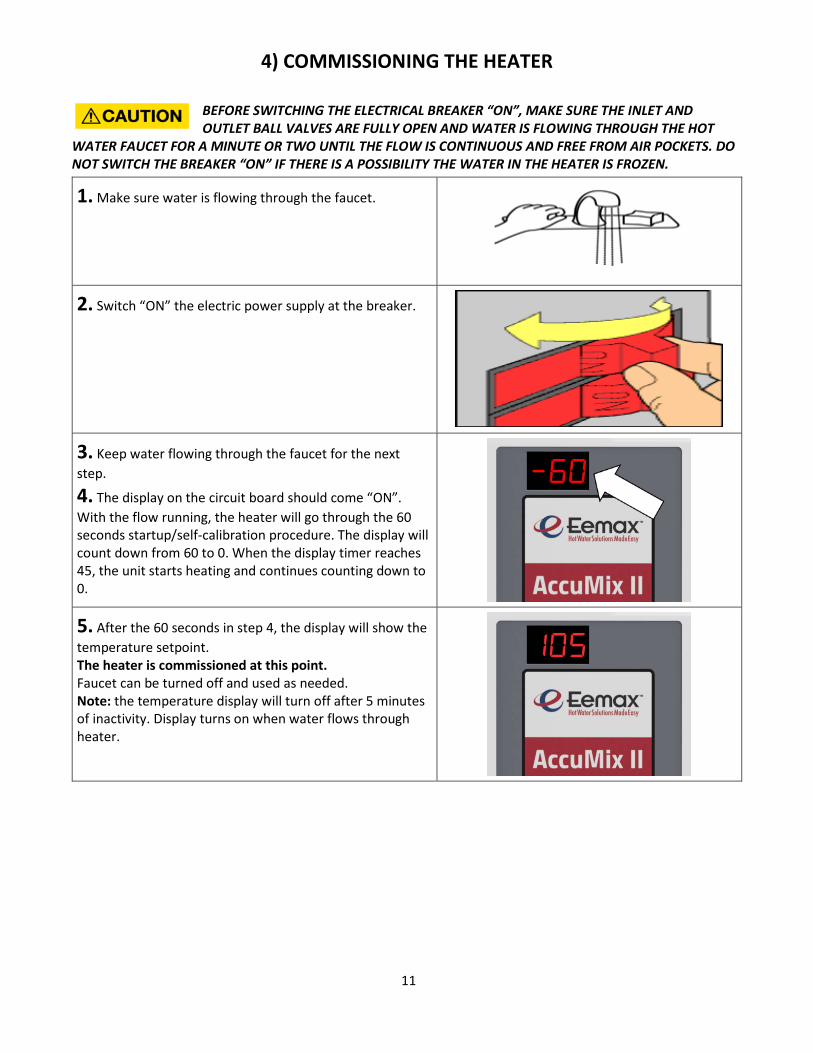
1. Make sure water is flowing through the faucet.
2. Switch “ON” the electric power supply at the breaker.
3. Keep water flowing through the faucet for the next step.
4. The display on the circuit board should come “ON”. With the flow running, the heater will go through the 60 seconds startup/self-calibration procedure. The display will count down from 60 to 0. When the display timer reaches 45, the unit starts heating and continues counting down to 0.
5. After the 60 seconds in step 4, the display will show the temperature setpoint. The heater is commissioned at this point. Faucet can be turned off and used as needed. Note: the temperature display will turn off after 5 minutes of inactivity. Display turns on when water flows through heater.

12
Congratulations!
Your Eemax tankless electric water heater is fully installed and ready for use!
MAXIMUM TEMPERATURE RISE AT SPECIFIED FLOW RATE, °F
240VAC heaters used at 208VAC GPM GPM
Model 0.5 1.0 1.5 0.5 1.0 1.5 AM004120T 48 24 16 x x x AM005240T 66 33 22 49 24 16 AM007240T 89 44 30 66 33 22 AM010240T 130 65 43 97 48 32 AM012240T 157 79 52 118 59 39 AM004277T 56 28 19 x x x AM008277T 109 55 36 x x x AM010277T 137 68 46 x x x
*The heaters’ actual temperature rises are limited by their thermostatic controls. The theoretical values shown above are only for comparison purposes.

13
5) TROUBLESHOOTING
For fault code resolution, please consult the table below. For advanced troubleshooting, please call our Technical Service Department.
Fault code Fault name Possible causes Heater response Possible solutions
F23 No heat
- element failure - ECO tripped/malfunctioning - triac(s) failed open - relay/contactor malfunctioning - control board failure - inlet thermistor failure - inlet water supply out of spec
- unit attempts to operate for 30 seconds, then shuts down* if condition continues
- verify inlet water pressure fluctuations are not present, then cycle the power to the unit
F24 Low heat
- severe undervoltage - triac(s) failed open - control board failure - inlet/outlet thermistor(s) failure
- unit keeps running at reduced performance (lower outlet temperature)
- verify power supply (voltage) while heater is running
F33 Shorted triacs
- both triacs failed closed - unit shuts down*
F34 Overvoltage
- inlet voltage is too high compared to the stated heater specifications
- unit shuts down* - have certified personnel verify the inlet voltage - inlet voltage drops below fault threshold
F36 Undervoltage
- inlet voltage is too low compared to the stated heater specifications
- unit keeps running at reduced performance (lower outlet temperature)
- have certified personnel verify the inlet voltage - inlet voltage rises over fault threshold
F38 High flow
- flow is too high to heat the water to setpoint temperature
- unit keeps running at reduced performance (lower outlet temperature)
- reduce flow (outlet flow restrictor, faucet aerator)
F47 Inlet thermistor failure
- inlet thermistor interrupted or disconnected
- unit keeps running at reduced performance (longer response time)
F48 Outlet thermistor failure
- outlet thermistor interrupted or disconnected
- unit keeps running at reduced performance (difficulties maintaining setpoint temperature due to inlet voltage fluctuations)
F64 Freeze warning
- inlet temperature is too low (below 35°F) - inlet thermistor failure
- unit shuts down*

14
F83 Inverted flow - water flows through the heater in the wrong direction
- unit shuts down* - reinstall the unit correctly
F99 Heater disabled
- caused after a power cycle, if a critical error was previously present (such as F33, F64, F83)
- unit will not turn on
Note:
* “shut down” means the control board stops applying heat to the heating elements, but the control board and diagnostic functions remain active
Still having trouble? Please call our Technical Service Department.
6) PERIODIC MAINTENANCE
This heater is designed for many years of carefree use. In order to maintain consistent water flow, it may be necessary to periodically clean the faucet aerator or the filter screen located in the brass inlet fitting at the heater.
Heating chamber Triacs Energy cut-off (ECO) Control board Contactor
ELEMENT CARTRIDGE (pictured below) INSTALLS INSIDE HEATING CHAMBER

15
7) PART NUMBERS FOR FITTINGS, AERATORS AND AERATOR ADAPTORS
COMPRESSION FITTINGS:
AERATORS: 3/8" NUT EX68B 0.5 GPM EX0061-0.5-AER 3/8" SLEEVE EX68C
8) REPAIR PARTS FOR ACCUMIX II UNITS
Model number Element cartridge Control board Relay Energy Cut-Off (ECO)
AM004120T EX410 EX384-120 EX259B EX278A-KIT AM004277T EX1920 EX384-277 EX253B EX278A-KIT AM005240T EX1200 EX384-240 EX255B EX278A-KIT AM007240T EX890 EX384-240 EX255B EX278A-KIT AM008277T EX960 EX384-277 EX253B EX278A-KIT AM010240T EX630 EX384-240 EX255B EX278A-KIT AM010277T EX760 EX384-277 EX253B EX278A-KIT AM012240T EX500 PRT EX384-240 EX1050-1
(contactor) EX278A-KIT
If you need any assistance from our Technical Service Department, make sure you can identify this water heater by having the model no:____________________ and serial number:_____________________.
Call 203-267-7890 or toll free: 800-543-6163.
Eemax Inc., 400 Captain Neville Drive, Waterbury, CT 06705
Tel: 800-543-6163, 203-267-7890, Fax: 203-267-7975, email: [email protected]

16
Notes:
Eemax Inc., 400 Captain Neville Drive, Waterbury, CT 06705
Tel: 800-543-6163, 203-267-7890, Fax: 203-267-7975, email: [email protected]
EX07200-83 Rev A


![JAXMSTR - [01 35 26.PRN] · american national standards institute (ansi/asse) ansi/asse a10.32 (2004) fall protection ansi/asse a10.34 ... jaxmstr - [01 35 26.prn]](https://img.pdfslide.us/doc/110x75/5b09ac947f8b9a93738e38e9/jaxmstr-01-35-26prn-national-standards-institute-ansiasse-ansiasse-a1032.jpg)