Embed Size (px)
Citation preview

4-1
ACC
ESSO
RIES
ACCESSORIES
P LINE ON LINE PAGE 4-3
P FLOW MICRO-REGULATOR PAGE 4-23
P AUxILIARy vALvEs PAGE 4-29
P PNEUMATIC LOGIC PAGE 4-32
P sILENCER PAGE 4-36

4-2
ACC
ESSO
RIES

4-3
ACC
ESSO
RIES
sUM
MA
Ry LI
NE-
ON
-LIN
E
SUMMARY
P INTRODUCTION LINE-ON-LINE PAGE 4-4
P IN-LINE SOLENOID VALVES SERIES SOV L PAGE 4-6
P MINIATURE REDUCER SERIES RML PAGE 4-8
P IN-LINE PRESSURE GAUGE SERIES MAN L PAGE 4-10
P IN-LINE PRESSURE INDICATOR SERIES LAM L PAGE 4-12
P IN-LINE SHUTOFF VALVES SERIES V2V L - V3V L PAGE 4-14
P IN-LINE FLOW MICRO REGULATOR SERIES RFL L PAGE 4-16
P IN-LINE QUICK-EXHAUST VALVES SERIES VSR L PAGE 4-18
P IN-LINE CHECK VALVE SERIES VNR L PAGE 4-20
P LINE-ON-LINE ACCESSORIES PAGE 4-22

4-4
ACC
ESSO
RIES
CONNECTION FREE
FIXING FREE
Line on Line is an exclusive range of products for mounting on pneumatic circuits. With these small, highly efficient components it is possible to perform all pneumatic functions at any point of the circuit. Line on Line is ultra-modular - the components can be connected in parallel, in series or combined parallel/series. All Line on Line products are available for pipe-pipe connection with two push in fittings. Adding an RU6 fitting, it is possible to have a pipe-NPT thread connection.The body is made of technopolymer, giving a product that is extremely lightweight and compact. One side of the body is marked with an indelible pneumatic symbol to facilitate identification and indicate the direction of flow.
PARALLEL LINEs sERIAL LINE PARALLEL FITTING sERIAL LINE IN-LINE FITTING
WALL FIxING PLATE FIxING PANEL FIxING UNDER WALL FIxING
INTR
ODU
CTIO
N LI
NE-
ON
-LIN
E
LINE OF PRODUCTS ON LINE

4-5
ACC
ESSO
RIES
ALL THE PNEUMATIC FUNCTIONS WITH THE SAME EXTERNAL DIMENSIONS
PIPE-PIPE
APPLICATION EXAMPLE
THREAD-PIPE
INTR
ODU
CTIO
N LI
NE-
ON
-LIN
E
Thank to the RU6 fitting, with his male NPT thread, it is possible to fit all line on line productsdirectly on female threads,i.e. on cylinders or valves.

4-6
ACC
ESSO
RIES
sOv L solenoid valves belong to the LINE ON LINE® family, which means they can be connected to all the other components in series or in parallel.Available in the version for pipe-pipe connection with two push-in fittings.Though small in size, sOv L valves are solenoid-piloted and feature very high performance. The spool distributor is fitted with special polyurethane gaskets to ensure a very long working life. Each valve comes complete with a monostable manual control and LED.Exhaust can be damped with an annular silencer.
ASSEMBLY OPTIONS
A B C
How to mount the sOv L:• Fig. A Adding a RU6 fitting, with his male NPT thread, it is possible to mount the sOv L straight on to the actuator or the control valve.• Fig. B Fixing to the plate with the special sQU L bracket.• Fig. C There are two robust rings on the plastic body for fixing the sOv L straight onto the wall.
IN-L
INE
sOLE
NO
ID v
ALv
E sE
RIEs
sO
v L
IN-LINE SOLENOID VALVE SERIES SOV L
TECHNICAL DATAOperating pressure MPa bar psiTemperature range °C °FFlow rate at 6.3 bar (0.63 MPa - 91 psi) ΔP 0.5 bar (0.1 Mpa - 7.25 psi) Nl/min scfmFlow rate at 6.3 bar (0.63 MPa - 91 psi) ΔP 1 bar (0.1 Mpa - 14.5 psi) Nl/min scfmConductance C Nl/min·barCoefficient b bar/barvoltage vDCPower WRecommended pipeFluid
Ø 1/4 Ø 5/16
0.25 - 0.72.5 - 7
36 - 101–10 to +60
+14 to +140 270 500 9.5 17.7 380 700 13.4 24.7 95.8 178.1 0.145 0.129
240.9
Rilsan PA11 - Nylon 6 - Polyamide 12 - PolypropyleneLubricated or unlubricated filtered compressed air

4-7
ACC
ESSO
RIES
PLUG-IN CONNECTOR
Code DescriptionW0970512000 Plug-in connector
Mach 11 L = 11.8 inch
PLUG-IN PILOT
Code Description722213541100 PLT-10 722213541100
SOV L 3/2 NC-NO PIPE-PIPE CONVEYED EXHAUST
SOV L 3/2 NC-NO PIPE-PIPE SILENCED EXHAUST
ACCESSORIES SPARES
IN-L
INE
sOLE
NO
ID v
ALv
E sE
RIEs
sO
v L
Code Ref. Ø A B C D E I I19069016U sOv L 3/2 NC 1/4-1/4 1/4 1.95 2.26 0.58 0.25 0.45 0.57 0.799069116U sOv L 3/2 NO 1/4-1/49069024 sOv L 3/2 NC 5/16-5/16 5/16 2.26 2.5 0.74 0.36 0.54 0.74 0.949069124 sOv L 3/2 NO 5/16-5/16
Code Ref. Ø A B C D E F I I1 L9069216U sOv L 3/2 NC 1/4-1/4-1/4 1/4 1.95 2.26 0.58 0.25 0.45 Ø 1/4 0.57 0.79 1.119069316U sOv L 3/2 NO 1/4-1/4-1/49069224 sOv L 3/2 NC 5/16-5/16-5/16 5/16 2.26 2.5 0.74 0.36 0.54 Ø 5/16 0.74 0.94 1.189069324 sOv L 3/2 NO 5/16-5/16-5/16
ø 0.13
ø 0.13

4-8
ACC
ESSO
RIES
The RML R miniature pressure regulator belongs to the LINE ON LINE® family and can be connected in series or in parallel with all the other products.The miniature pressure regulator is available in five different types:• In-line with push-in input and output fitting• In-line with threaded input port and push-in output fitting • In-line with push-in input fitting and threaded output port• At an angle with threaded input port and push-in output fitting• Cartridge type for direct assembly in suitably worked slot. The miniature pressure regulator is fitted with a relief valve for over-pressure exhaust.• Particularly suitable for use between the valve and actuator and as a pressure regulator in secondary branches of the pneumatic system.
TECHNICAL DATA
COMPONENTS
Regulation rangeInlet pressure MPa bar psiFlow rate at 6.3 bar (0.63 MPa - 91 psi) ΔP 1 bar (0.1 MPa - 14.5 psi) Nl/min scfmFlow rate on exhaust at 6.3 bar (0.63 MPa - 91 psi) Nl/min scfmFluidMax. temperature at 1 MPa; 10 bar; 145 psi °C °FAssembly positionNotes
RML Ø 1/4 RML Ø 5/16
1 to 8 bar - 0.1 to 0.8 MPa - 14.5 to 116 psi0.2 - 12 - 10
29 - 145 150 260 5.3 9.2 400 600 14 21.2
Lubricated or unlubricated filtered air– 20 to + 60– 4 to + 140
AvailableIn the miniature regulator the pressure must always be set upwards.
a Technopolymer bodyb Nickel-plated brass insertc Nickel-plated brass adjusting screwd steel adjusting springe Brass piston rodf NBR shutterg stainless steel shutter springh Adjusting screw ring nuti Nickel-plated brass wall ring nutj Technopolymer release bushingk Technopolymer stop bushing l stainless steel crimping springm Technopolymer spring ring n NBR gasket
MIN
IATU
RE R
EDUC
ER/E
CON
OM
IZER
, sER
IEs
RML
MINIATURE REDUCER/ECONOMIZER, SERIES RML

4-9
ACC
ESSO
RIES
ASSEMBLY OPTIONS
POSSIBLE APPLICATIONS
A B D
How to assembly RML:• Fig. A Adding a RU6 fitting, with his male NPT thread, it is possible to mount the RML straight on to the actuator or the control valve.• Fig. B By using the ring nut screwed on the threaded body it’s possible the assembling on panels.• Fig. C On the plastic body there are two strong ring for the direct wall assembly.• Fig. D Fixing on plate trought the proper small square sQU L.
C
ECONOMIZER REMOTE REDUCERIf in a cylinder you require a thrust in one direction only, e.g. piston rod extension, and a lower thrust and pressure is sufficient in the other direction, you can save a lot of energy by mounting an economizer valve.
ExampleCylinder Ø 80 mm, stroke 200 mm, 6 bar, 12 cycles/min, 16 hours a day, 230 days a year.Consumption: 144 Nl/min => 3460 kWh/year => 880 litres of oil => 2428 kg of CO2 => € 346/year.If you install an economizer that reduces the pressure from 6 to 2 bar, you sAvE: € 115/year.
P1 . P2P1 . P2
MIN
IATU
RE R
EDUC
ER/E
CON
OM
IZER
, sER
IEs
RML
LINE-MOUNTED MINIATURE REDUCER, SERIES RML
Code Ref. Ø A B C D E G H I I1 Ch Nmax9061316U RML 1/4-1/4 1/4 1.85 1.81-2.05 0.58 0.25 0.45 0.98 M9x0.75 0.57 0.79 0.43 0.189061324 RML 5/16-5/16 5/16 2.18 2.05-2.28 0.74 0.36 0.54 1.08 M11x1 0.74 0.94 0.51 0.15
ø 0.13
4-10
ACC
ESSO
RIES
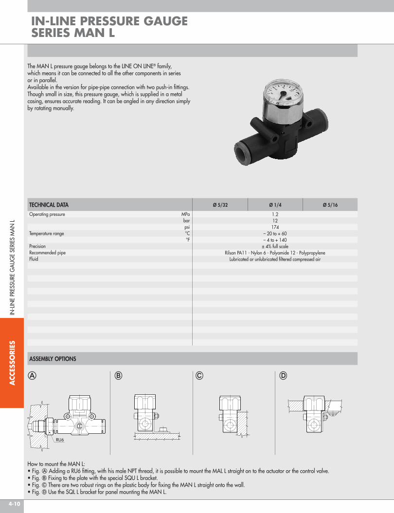
The MAN L pressure gauge belongs to the LINE ON LINE® family, which means it can be connected to all the other components in series or in parallel.Available in the version for pipe-pipe connection with two push-in fittings.Though small in size, this pressure gauge, which is supplied in a metal casing, ensures accurate reading. It can be angled in any direction simply by rotating manually.
TECHNICAL DATA
ASSEMBLY OPTIONS
Operating pressure MPa bar psiTemperature range °C °FPrecisionRecommended pipeFluid
Ø 5/32 Ø 1/4 Ø 5/16
1.212174
– 20 to + 60– 4 to + 140
± 4% full scaleRilsan PA11 - Nylon 6 - Polyamide 12 - Polypropylene
Lubricated or unlubricated filtered compressed air
A B D
How to mount the MAN L:• Fig. A Adding a RU6 fitting, with his male NPT thread, it is possible to mount the MAL L straight on to the actuator or the control valve.• Fig. B Fixing to the plate with the special sQU L bracket.• Fig. C There are two robust rings on the plastic body for fixing the MAN L straight onto the wall.• Fig. D Use the sQL L bracket for panel mounting the MAN L.
C
IN-L
INE
PREs
sURE
GA
UGE
sERI
Es M
AN
L
IN-LINE PRESSURE GAUGE SERIES MAN L

4-11
ACC
ESSO
RIES
MAN L PIPE-PIPE
Code Ref. Ø A B C D E E1 I I19067001 MAN L 5/32-5/32 5/32 1.65 1.42 0.42 0.22 0.39 0.9 0.5 0.639067016U MAN L 1/4-1/4 1/4 1.95 1.38 0.58 0.25 0.45 0.9 0.57 0.799067024 MAN L 5/16-5/16 5/16 2.26 1.61 0.74 0.36 0.54 0.9 0.74 0.94
IN-L
INE
PREs
sURE
GA
UGE
sERI
Es M
AN
L
NOTES
ø 0.13

4-12
ACC
ESSO
RIES
The LAM L pneumatic light indicator belongs to the LINE ON LINE® family, which means it can be connected to all the other components in series or in parallel.Available in the version for pipe-pipe connection with two push-in fittings.When there is no pressure, the clear technopolymer bell looks empty. When there is pressure, a red signal appears.The clear bell can be cleaned using normal detergents or ethyl alcohol, as the technopolymer used is fully compatible.
TECHNICAL DATA
ASSEMBLY OPTIONS
Operating pressure MPa bar psiTemperature range °C °FFlow rate at 6.3 bar (0.63 MPa - 91 psi) ΔP 1 bar (0.1 Mpa - 14.5 psi) Nl/min scfmColour with pressureRecommended pipeFluid
Ø 1/4 Ø 5/16
0.2 - 12 - 10
29 - 145– 20 to + 60– 4 to + 140
420 800 14.8 28.3
Orange - GreenRilsan PA11 - Nylon 6 - Polyamide 12 - Polypropylene
Lubricated or unlubricated filtered compressed air; if used, must be continuous
A B D
How to mount the LAM L:• Fig. A Adding a RU6 fitting, with his male NPT thread, it is possible to mount the LAM L straight on to the actuator or the control valve.• Fig. B Fixing to the plate with the special sQU L bracket.• Fig. C There are two robust rings on the plastic body for fixing the LAM L straight onto the wall.• Fig. D The ring nut is screwed onto the threaded metal part of the LAM L body for panel mounting.
C
IN-L
INE
PREs
sURE
INDI
CATO
R sE
RIEs
LAM
L
IN-LINE PRESSURE INDICATOR SERIES LAM L

4-13
ACC
ESSO
RIES
LAM L PIPE-PIPE
NOTES
IN-L
INE
PREs
sURE
INDI
CATO
R sE
RIEs
LAM
L
Code Ref. Ø A B C D E E1 G H I I1 Ch Nmax9068016U LAM L 1/4-1/4-A 1/4 1.95 1.46 0.58 0.25 0.45 0.42 0.83 M15x1 0.57 0.79 0.67 0.189068216U LAM L 1/4-1/4-v9068024 LAM L 5/16-5/16-A 5/16 2.26 1.61 0.74 0.36 0.54 0.42 1.02 M15x1 0.74 0.94 0.67 0.189068224 LAM L 5/16-5/16-v
A = Orangev = Green
ø 0.13

4-14
ACC
ESSO
RIES
v2v L and v3v L shutoff valves belong to the LINE ON LINE® family which means they can be connected to all the other components in series or in parallel.Available in the version for pipe-pipe connection with two push-in fittings.v2v is a two-way unidirectional valve, while v3v is a three-way valve with free discharge in the area around the control knob. The locked version is probably the smallest available on the market. A lock is provided to ensure the valve is kept in the closed position during machine maintenance. The valve is supplied complete with a lock and two keys.
IN-L
INE
sHUT
OFF
vA
LvE
sERI
Es v
2v L
AN
D v3
v L
IN-LINE SHUTOFF VALVE SERIES V2V L AND V3V L
COMPONENTS
a Technopolymer bodyb Nickel-plated brass insertc Brass rodd Technopolymer knobe NBR valvef stainless steel valve compression springg Nickel-plated brass wall-mount ring nuth NBR gasketi Technopolymer spring ringj stainless steel folding springk Technopolymer locking bushingl Technopolymer release bushing
TECHNICAL DATAOperating pressure MPa bar psiTemperature range °C °FFlow rate at 6.3 bar (0.63 MPa - 91 psi) ΔP 1 bar (0.1 MPa - 14.5 psi) Nl/min scfmFlow rate on exhaust at 6.3 bar (0.63 MPa - 91 psi) Nl/min scfmRecommended pipeFluid
Ø 1/4 Ø 5/16
110145
– 20 to + 60– 4 to + 140
280 470 10 16.6 110 110 3.8 3.8
Rilsan PA11 - Nylon 6 - Polyamide 12 - PolypropyleneLubricated or unlubricated filtered compressed air; if used, must be continuous

4-15
ACC
ESSO
RIES
V2V/V3V L PIPE-PIPE PADLOCKED
Code Ref. Ø A B C D E G H I I1 Ch Nmax9065116U v2v L 1/4-1/4 KEy 1/4 1.95 1.61 0.58 0.25 0.45 0.83 M15x1 0.57 0.79 0.67 0.229066116U v3v L 1/4-1/4 KEy9065124 v2v L 5/16-5/16 KEy 5/16 2.26 1.81 0.74 0.36 0.54 1.02 M15x1 0.74 0.94 0.67 0.229066124 v3v L 5/16-5/16 KEy
IN-L
INE
sHUT
OFF
vA
LvE
sERI
Es v
2v L
AN
D v3
v L
ASSEMBLY OPTIONS
A B D
How to mount the v2v/v3v L:• Fig. A Adding a RU6 fitting, with his male NPT thread, it is possible to mount the v2v/v3v L straight on to the actuator or the control valve.• Fig. B Fixing to the plate with the special sQU L bracket.• Fig. C There are two robust rings on the plastic body for fixing the v2v/v3v L straight onto the wall.• Fig. D The rig nut is screwed onto the threaded metal part of the v2v/v3v L body for panel mounting.
C
V2V/V3V L PIPE-PIPE
Code Ref. Ø A B C D E G H I I1 Ch Nmax9065016U v2v L 1/4-1/4 1/4 1.95 1.61 0.58 0.25 0.45 0.83 M15x1 0.57 0.79 0.67 0.229066016U v3v L 1/4-1/49065024 v2v L 5/16-5/16 5/16 2.26 1.81 0.74 0.36 0.54 1.02 M15x1 0.74 0.94 0.67 0.229066024 v3v L 5/16-5/16
ø 0.13
ø 0.13

4-16
ACC
ESSO
RIES
The RLF L flow micro-regulator belongs to the LINE ON LINE® family and can be connected in series or in parallel with all the other products.The RFL L regulates the air input and thus the speed in pneumatic actuators. Two versions are available:• Type U (unidirectional) regulates the flow only in one of the two directions of air flow. The following types of fitting can be mounted: - Push-in input and output fitting• Type B (bidirectional) regulates the flow in both directions of air flow. The following types of fitting can be mounted: - Push-in input and output fitting - Threaded port and push-in fittingThere are four possible types of assembly (see example on the following page).
TECHNICAL DATA
ASSEMBLY OPTIONS
Max. operating pressure MPa bar psiTemperature range °C °FMax flow rate on regulation at 6.3 bar (0.63 MPa - 91 psi) Nl/min scfmFlow rate on exhaust at 6.3 bar (0.63 MPa - 91 psi) Nl/min scfmAdjustmentInternal systemRecommended pipeFluidCompatibility with oils
Ø 5/32 Ø 1/4 Ø 5/16
110145
– 20 to + 60– 4 to + 140
155 450 850 5.5 16 30 160 550 950 5.6 19.5 33.6
Manual or using a screwdriverTapered needle
Rilsan PA 11 - Nylon 6 - Polyamide 12 - PolypropyleneLubricated or unlubricated filtered air
Please refer to page 5-4 of the tecnical documentation
A B D
How to mount the RFL L:• Fig. A Adding a RU6 fitting, with his male NPT thread, it is possible to mount the RFL L straight on to the actuator or the control valve.• Fig. B Fixing to the plate with the special sQU L bracket.• Fig. C There are two robust rings on the plastic body for fixing the RFL L straight onto the wall.• Fig. D The ring nut is screwed onto the threaded metal part of the RFL L body for panel mounting.
C
COMPONENTS
a Technopolymer bodyb Nickel-plated brass seal supportc NBR gasketd Brass adjusting needlee Nickel-plated brass needle ring nutf Wall fixing ring nutg NBR sealh Technopolymer spring ringi stainless steel clip-on springj Technopolymer stop bushingk Technopolymer release bushing
UNIDIRECTIONAL BIDIRECTIONAL
IN-L
INE
FLO
W M
ICRO
-REG
ULAT
OR
sERI
E RF
L L
IN-LINE FLOW MICRO-REGULATOR SERIE RFL L

4-17
ACC
ESSO
RIES
RFL L PIPE-PIPE BIDIRECTIONAL
FLOW RATE CHARTS AT 6.3 bar (0.63 MPa - 91 psi) DEPENDING ON THE TURNS EFFECTED BY THE REGULATION SCREW
RFL L PIPE-PIPE UNIDIRECTIONAL
RFL L Ø 5/32 RFL L Ø 1/4 RFL L Ø 5/16
P (N
l/m
in)
Turns no. Turns no. Turns no.
Code Ref. Ø A B C D E G H I I1 Ch Nmax9041301 RFL L U 5/32-5/32 5/32 1.65 1.32-1.44 0.42 0.22 0.39 0.69 M9x0.75 0.5 0.63 0.43 0.169041316U RFL L U 1/4-1/4 1/4 1.95 1.42-1.61 0.58 0.25 0.45 0.79 M12x0.75 0.57 0.79 0.59 0.169041324 RFL L U 5/16-5/16 5/16 2.26 1.73-1.93 0.74 0.36 0.54 1.02 M15x1 0.74 0.94 0.79 0.18
P (N
l/m
in)
P (N
l/m
in)
IN-L
INE
FLO
W M
ICRO
-REG
ULAT
OR
sERI
E RF
L L
Code Ref. Ø A B C D E G H I I1 Ch Nmax9041601 RFL L B 5/32-5/32 5/32 1.65 1.32-1.44 0.42 0.22 0.39 0.69 M9x0.75 0.5 0.63 0.43 0.169041616U RFL L B 1/4-1/4 1/4 1.95 1.42-1.61 0.58 0.25 0.45 0.79 M12x0.75 0.57 0.79 0.59 0.169041624 RFL L B 5/16-5/16 5/16 2.26 1.73-1.93 0.74 0.36 0.54 1.02 M15x1 0.74 0.94 0.79 0.18
ø 0.13
ø 0.13

4-18
ACC
ESSO
RIES
The vsR L quick-exhaust valve belongs to the LINE ON LINE® family, which means it can be connected to all the other components in series or in parallel. Available in the version for pipe-pipe connection with two push-in fittings. Exhaust can be silenced using a sTAINLEss steel wire silencer, or conveyed using a push-in fitting.
TECHNICAL DATAInlet pressure MPa bar psiTemperature range °C °FInlet flow rate at 6.3 bar (0.63 MPa - 91 psi) ΔP 1 bar (0.1 MPa - 14.5 psi) Nl/min scfmExhaust flow rate at 6.3 bar (0.63 MPa - 91 psi) Nl/min scfmRecommended pipeFluidCompatibility with oils
Ø 5/32 Ø 1/4 Ø 5/16
0.1 - 11 - 10
14.5 - 145–20 to +60–4 to +140
50 270 400 1.8 9.5 14 100 700 1000 3.5 24.7 35.3
Rilsan PA 11 - Nylon 6 - Polyamide 12 - PolypropyleneLubricated or unlubricated filtered compressed air; if used, must be continuous
Please refer to page 5-4 of the tecnical documentation
COMPONENTS
a Technopolymer bodyb Nickel-plated brass insertc NBR valved NBR gaskete Technopolymer spring ringf stainless steel folding springg Brass or technopolymer locking bushingh Technopolymer release bushingi stainless steel wire silencer
IN-L
INE
QUI
CK-E
xHA
UsT
vALv
Es s
ERIE
s vs
R L
IN-LINE QUICK-EXHAUST VALVES SERIES VSR L

4-19
ACC
ESSO
RIES
IN-L
INE
QUI
CK-E
xHA
UsT
vALv
Es s
ERIE
s vs
R L
ASSEMBLY OPTIONS
A B
How to mount the vsR L:• Fig. A Adding a RU6 fitting, with his male NPT thread, it is possible to mount the vsR L straight on to the actuator or the control valve.• Fig. B Fixing to the plate with the special sQU L bracket.• Fig. C There are two robust rings on the plastic body for fixing the vsR L straight onto the wall.
C
VSR L PIPE-PIPE, CONVEYED EXHAUST
Code Ref. Ø A B C D E E1 I I19063001 vsR L 5/32-5/32-5/32 5/32 1.65 1.02 0.42 0.22 0.39 0.38 0.5 0.639063016U vsR L 1/4-1/4-1/4 1/4 1.95 1.18 0.58 0.25 0.45 0.51 0.57 0.799063024 vsR L 5/16-5/16-5/16 5/16 2.26 1.41 0.74 0.36 0.54 0.59 0.74 0.94
VSR L PIPE-PIPE, SILENCED EXHAUST
Code Ref. Ø A B C D E E1 I I19063101 vsR L 5/32-5/32-sIL 5/32 1.65 0.78 0.42 0.22 0.39 0.39 0.5 0.639063116U vsR L 1/4-1/4-sIL 1/4 1.95 1 0.58 0.25 0.45 0.51 0.57 0.799063124 vsR L 5/16-5/16-sIL 5/16 2.26 1.24 0.74 0.36 0.54 0.71 0.74 0.94
ø 0.13
ø 0.13

4-20
ACC
ESSO
RIES
The vNR L check valve belongs to the LINE ON LINE® family, which means it can be connected to all the other components in series or in parallel.Available in the version for pipe-pipe connection with two push-in fittings.It is still the only check valve with holes for wall mounting.
TECHNICAL DATAOperating pressure MPa bar psiTemperature range °C °FFlow rate at 6.3 bar (0.63 MPa - 91 psi) ΔP 1 bar (0.1 MPa - 14.5 psi) Nl/min scfmRecommended pipeFluid
Ø 5/32 Ø 1/4 Ø 5/16
0.05 - 1.20.5 - 127.2 - 174
–20 to +60–4 to +140
80 320 480 2.8 11.3 17
Rilsan PA11 - Nylon 6 - Polyamide 12 - PolypropyleneLubricated or unlubricated filtered compressed air
IN-L
INE
CHEC
K vA
LvE
sERI
Es v
NR
L
IN-LINE CHECK VALVE SERIES VNR L
COMPONENTS
a Technopolymer bodyb Nickel-plated brass insertc NBR valved stainless steel valve compression springe NBR gasketf Technopolymer spring ringg stainless steel folding springh Technopolymer locking bushingi Technopolymer release bushing

4-21
ACC
ESSO
RIES
NOTES
ASSEMBLY OPTIONS
A B
How to mount the vNR L:• Fig. A Adding a RU6 fitting, with his male NPT thread, it is possible to mount the vNR L straight on to the actuator or the control valve.• Fig. B Fixing to the plate with the special sQU L bracket.• Fig. C There are two robust rings on the plastic body for fixing the vNR L straight onto the wall.
C
IN-L
INE
CHEC
K vA
LvE
sERI
Es v
NR
L
VNR L PIPE-PIPE
Code Ref. Ø A B C D E I I19064001 vNR L 5/32-5/32 5/32 1.65 0.69 0.42 5.6 0.39 0.5 0.639064016U vNR L 1/4-1/4 1/4 1.95 0.79 0.58 0.25 0.45 0.57 0.799064024 vNR L 5/16-5/16 5/16 2.26 1 0.74 0.36 0.54 0.73 0.94
ø 0.13

4-22
ACC
ESSO
RIES
FIXING SQUARE KIT
U-BOLT
RU6 - STEM ADAPTORS
Code Description A B C F I I1 I2 I3 I4 I5 S9062110 sQU L 1.18 0.87 0.57 0.16 0.27 0.19 0.23 0.36 0.08 0.25 0.05
NOTE: comes with two M3x16 screws (for L.O.L. Ø 1/4 - 5/16), two M3 hexagonal nuts, 2 groovers, 4 washers.
Code Description9062216U TUB L 1/4-1/49062224 TUB L 5/16-5/16
ACC
EssO
RIEs
LIN
E O
N LI
NE®
ACCESSORIES LINE ON LINE®
ChCode Ref Ø F Inc mm P L D E2U06001 RU6 5/32 10/32 UNF 5/16 8 0.16 0.99 0.08 0.352U06002 RU6 5/32 1/8 NPT 0.472 12 0.24 1.09 0.10 0.512U06003 RU6 5/32 1/4 NPT 0.551 14 0.31 1.19 0.10 0.652U06000 RU6 1/4 10/32 UNF 5/16 8 0.16 1.01 0.08 0.352U06007 RU6 1/4 1/8 NPT 0.472 12 0.24 1.11 0.16 0.512U06008 RU6 1/4 1/4 NPT 0.551 14 0.31 1.20 0.16 0.652U06020 RU6 1/4 3/8 NPT 0.669 17 0.35 1.31 0.16 0.792U06009 RU6 5/16 1/8 NPT 0.472 12 0.24 1.15 0.22 0.512U06010 RU6 5/16 1/4 NPT 0.551 14 0.31 1.24 0.24 0.652U06011 RU6 5/16 3/8 NPT 0.669 17 0.35 1.35 0.24 0.79

4-23
ACC
ESSO
RIES
SUMMARY FLOW MICRO-REGULATOR
P FLOW MICRO-REGULATOR PAGE 4-24
sUM
MA
Ry F
LOW
MIC
RO-R
EGUL
ATO
R

4-24
ACC
ESSO
RIES
The job of flow microregulators is to regulate speed in the pneumatic cylinders. The configuration of both type C (to be mounted on the cylinder inlet) and type v (to be mounted on the valve port) is such as to ensure full flow on feed and regulated flow on discharge. Type B (bidirectional) can be used to regulate the flow both on feed and discharge. Flow microregulators have reduced dimensions and fine adjustment in the first turns; they can be adjusted using the knob and/or screwdriver; adjustment can be prevented by tightening the ring nut.
Main features:• reduced dimensions• excellent regulation• regulation with either a screwdriver and/or a knob, can be fixed with a ring nut (COMPACT N)• available in all sizes (from 10-32 UNF to 1/2” NPT) with a brass ring• can be mounted with an automatic screwdriver • comes with a ring that can rotate even with the MRF mounted in position.
TECHNICAL DATAPipeMax input pressure MPa bar psiTemperature range: Brass ring °C °FMax flow rate in regulation at 90 psi Nl/minMax flow rate full port at 90 psi with closed pin Nl/minMax flow rate full port at 90 psi with open pin Nl/minRegulationInternal systemFluid
10-32 UNF 1/8’’ NPT 1/4’’ NPT 3/8” NPT 1/2” NPT
Ø 5/32 Ø 1/4 Ø 5/32 Ø 1/4 Ø 5/16 Ø 3/8 Ø 1/4 Ø 5/16 Ø 3/8 Ø 1/2 Ø 3/8 Ø 1/2 Ø 1/21
10145
– 10 to + 70+ 14 to + 158
150 155 350 380 400 400 750 850 950 1000 1300 1400 2000 140 150 300 350 390 390 450 275 500 550 1050 1250 1750 240 245 450 600 650 650 850 1050 1150 1250 1700 2100 2700
Manual or using a screwdriverTapered pin
Filtered, lubricated or unlubricated compressed air
TYPE N COMPONENTS - 10-32 UNF THREAD
a Nichel-plated brass knobb Nickel-plated brass securing ring nutc Brass pind Nickel-plated brass bushe Nickel-plated brass body f Nickel-plated brass retaining ring g NBR gasketh Nickel-plated brass revolving ringi NBR gasketj Technopolymer spring supporting ringk stainless steel grabbing springl Technopolymer retaining bushm Technopolymer release bush
CyLINDER
vALvE
BIDIREC.
FLOW MICRO-REGULATORFL
OW
MIC
RO-R
EGUL
ATO
R

4-25
ACC
ESSO
RIES
TYPE N COMPONENTS - THREAD 1/8” TO 1/2”
a Nickel-plated brass knobb Nickel-plated brass securing ring nutc Brass pind Nickel-plated brass bodye Nickel-plated brass retaining ringf Brass gasket holding insertg NBR gasketh Nickel-plated brass revolving ringi NBR gasketj Technopolymer spring supporting ringk stainless steel grabbing springl Technopolymer retaining bushm Technopolymer release bush
CyLINDER
vALvE
BIDIREC.
FLO
W M
ICRO
-REG
ULAT
OR
All the MRF with a pipe engage-release system of the latest generation that facilitates detachment of the pipe even under difficult operating conditions.
The rings can be rotated even with the MRF installed, which means that they can be mounted with the pipe facing towards any direction.
Thread MAX. TORQUE (lb ƒ ft)*10/32 1.331/8’’ NPT 4.331/4’’ NPT 5.903/8’’ NPT 7.381/2’’ NPT 11.06
* measured on a metal female thread
FLOW CHARTS
The regulation curve in the MRF COMPACT N, takes place in two sections: in the first half of the flash pin stroke for very fine regulation and relatively low flow rates; in the second half, the flash pin quickly opens the passage so as to reach the maximum flow rate quickly.
All the new MRF can be fixed from the top using a universal wrench, a pipe wrench or an automatic screwer.

4-26
ACC
ESSO
RIES
FLOW CHARTS
KEY TO CODES
MRF 10-32 UNF - PIPE Ø5-32 - Ø1/4 MRF 1/8” NPT - PIPE Ø5/32 - Ø1/4 - Ø5/16 - Ø3/8
MRF 1/4” NPT - PIPE Ø1/4 - Ø5/16 - Ø3/8 - Ø1/2 MRF 3/8” NPT - PIPE Ø3/8 - Ø1/2
MRF 1/2” NPT - PIPE Ø1/2
M R F N M C 1/4 1/8 NPTELEMENT TYPE RING FUNCTION Ø PIPE THREAD
N With knob and ring nut
M Nickel-plated brass with push-in fitting
C For cylinderV For valveB Bidirectional
5/32 Ø 5/321/4 Ø 1/45/16 Ø 5/163/8 Ø 3/81/2 Ø 1/2
10/32 UNF 10-32 UNF1/8 NPT 1/8’’ NPT1/4 NPT 1/4’’ NPT3/8 NPT 3/8’’ NPT1/2 NPT 1/2’’ NPT
FLO
W M
ICRO
-REG
ULAT
OR

4-27
ACC
ESSO
RIES
MRF COMPACT ‘‘N’’ BRASS RING
ChCode Description F Ø Inc mm A min A max B C D E9U31001C MRF N M C 5/32 10/32 UNF 10/32" UNF 5/32" 0.354 9 1.091 1.220 0.795 0.157 0.362 0.3749U31101V MRF N M v 5/32 10/32 UNF 10/32" UNF 5/32" 0.354 9 1.091 1.220 0.795 0.157 0.362 0.3749U31201B MRF N M B 5/32 10/32 UNF 10/32" UNF 5/32" 0.354 9 1.091 1.220 0.795 0.157 0.362 0.3749U31005C MRF N M C 1/4 10/32 UNF 10/32" UNF 1/4" 0.354 9 1.091 1.220 0.839 0.157 0.362 0.4659U31105V MRF N M v 1/4 10/32 UNF 10/32" UNF 1/4" 0.354 9 1.091 1.220 0.839 0.157 0.362 0.4659U31205B MRF N M B 1/4 10/32 UNF 10/32" UNF 1/4" 0.354 9 1.091 1.220 0.839 0.157 0.362 0.4659U31002C MRF N M C 5/32 1/8 UNF 1/8" NPT 5/32" 0.472 12 1.319 1.480 0.839 0.236 0.386 0.3749U31102V MRF N M v 5/32 1/8 UNF 1/8" NPT 5/32" 0.472 12 1.319 1.480 0.839 0.236 0.386 0.3749U31202B MRF N M B 5/32 1/8 UNF 1/8" NPT 5/32" 0.472 12 1.319 1.480 0.839 0.236 0.386 0.3749U31006C MRF N M C 1/4 1/8 NPT 1/8" NPT 1/4" 0.472 12 1.319 1.480 0.839 0.236 0.386 0.4659U31106V MRF N M v 1/4 1/8 NPT 1/8" NPT 1/4" 0.472 12 1.319 1.480 0.839 0.236 0.386 0.4659U31206B MRF N M B 1/4 1/8 NPT 1/8" NPT 1/4" 0.472 12 1.319 1.480 0.839 0.236 0.386 0.4659U31008C MRF N M C 5/16 1/8 NPT 1/8" NPT 5/16" 0.472 12 1.319 1.480 0.976 0.236 0.386 0.5439U31108V MRF N M v 5/16 1/8 NPT 1/8" NPT 5/16" 0.472 12 1.319 1.480 0.976 0.236 0.386 0.5439U31208B MRF N M B 5/16 1/8 NPT 1/8" NPT 5/16" 0.472 12 1.319 1.480 0.976 0.236 0.386 0.5439U31010C MRF N M C 3/8 1/8 NPT 1/8" NPT 3/8" 0.472 12 1.319 1.480 1.094 0.236 0.386 0.6509U31110V MRF N M v 3/8 1/8 NPT 1/8" NPT 3/8" 0.472 12 1.319 1.480 1.094 0.236 0.386 0.6509U31210B MRF N M B 3/8 1/8 NPT 1/8" NPT 3/8" 0.472 12 1.319 1.480 1.094 0.236 0.386 0.6509U31007C MRF N M C 1/4 1/4 NPT 1/4" NPT 1/4" 0.591 15 1.528 1.720 0.906 0.315 0.437 0.4659U31107V MRF N M v 1/4 1/4 NPT 1/4" NPT 1/4" 0.591 15 1.528 1.720 0.906 0.315 0.437 0.4659U31207B MRF N M B 1/4 1/4 NPT 1/4" NPT 1/4" 0.591 15 1.528 1.720 0.906 0.315 0.437 0.4659U31009C MRF N M C 5/16 1/4 NPT 1/4" NPT 5/16" 0.591 15 1.528 1.720 1.043 0.315 0.437 0.5439U31109V MRF N M v 5/16 1/4 NPT 1/4" NPT 5/16" 0.591 15 1.528 1.720 1.043 0.315 0.437 0.5439U31209B MRF N M B 5/16 1/4 NPT 1/4" NPT 5/16" 0.591 15 1.528 1.720 1.043 0.315 0.437 0.5439U31011C MRF N M C 3/8 1/4 NPT 1/4" NPT 3/8" 0.591 15 1.528 1.720 1.173 0.315 0.437 0.6509U31111V MRF N M v 3/8 1/4 NPT 1/4" NPT 3/8" 0.591 15 1.528 1.720 1.173 0.315 0.437 0.6509U31211B MRF N M B 3/8 1/4 NPT 1/4" NPT 3/8" 0.591 15 1.528 1.720 1.173 0.315 0.437 0.6509U31014C MRF N M C 1/2 1/4 NPT 1/4" NPT 1/2" 0.591 15 1.528 1.720 1.350 0.315 0.437 0.8279U31114V MRF N M v 1/2 1/4 NPT 1/4" NPT 1/2" 0.591 15 1.528 1.720 1.350 0.315 0.437 0.8279U31214B MRF N M B 1/2 1/4 NPT 1/4" NPT 1/2" 0.591 15 1.528 1.720 1.350 0.315 0.437 0.8279U31012C MRF N M C 3/8 3/8 NPT 3/8" NPT 3/8" 3/4 19 1.858 2.047 1.205 0.354 0.528 0.6309U31112V MRF N M v 3/8 3/8 NPT 3/8" NPT 3/8" 3/4 19 1.858 2.047 1.205 0.354 0.528 0.6309U31212B MRF N M B 3/8 3/8 NPT 3/8" NPT 3/8" 3/4 19 1.858 2.047 1.205 0.354 0.528 0.6309U31015C MRF N M C 1/2 3/8 NPT 3/8" NPT 1/2" 3/4 19 1.858 2.047 1.437 0.354 0.528 0.7959U31115V MRF N M v 1/2 3/8 NPT 3/8" NPT 1/2" 3/4 19 1.858 2.047 1.437 0.354 0.528 0.7959U31215B MRF N M B 1/2 3/8 NPT 3/8" NPT 1/2" 3/4 19 1.858 2.047 1.437 0.354 0.528 0.7959U31016C MRF N M C 1/2 1/2 NPT 1/2" NPT 1/2" 7/8 22 2.087 2.354 1.496 0.433 0.626 0.7959U31116V MRF N M v 1/2 1/2 NPT 1/2" NPT 1/2" 7/8 22 2.087 2.354 1.496 0.433 0.626 0.7959U31216B MRF N M B 1/2 1/2 NPT 1/2" NPT 1/2" 7/8 22 2.087 2.354 1.496 0.433 0.626 0.795
cylinderversion
valveversion
bidirectionalversion
FLO
W M
ICRO
-REG
ULAT
OR

4-28
ACC
ESSO
RIES
NOTES

4-29
ACC
ESSO
RIES
P QUICK EXHAUST VALVES SERIES VSR PAGE 4-30
P SLIDE VALVES SERIES VCS PAGE 4-31
P PNEUMATIC LOGIC PAGE 4-32
SUMMARY AUXILIARY VALVES
sUM
MA
Ry A
UxILI
ARy
vA
LvEs

4-30
ACC
ESSO
RIES
New, more compact and lighter version.Used to evacuate air in the cylinder quickly, which increases cylinder speed.• Temperature 0-80°C (32°-176°F)• Max. pressure 12 bar (1200 kPa - 203 psi)• Min. pressure 0.5 bar (50 kPa - 7.25 psi)
a Cap: nickel-plated brass for 1/8-1/4 anodised aluminium for 1/2b O-ring: NBRc Lip-seal: Polyurethaned Body: nickel-plated brass
COMPONENTS
OVERALL DIMENSIONS AND ORDERING CODES SPARE GASKETS
Code Ref. F B D CH L1 Weight [lb]9101201U vsR 1/8 1/8 0.73 1.16 0.55 (14 mm) 0.52 0.179201201U vsR 1/4 1/4 0.92 1.34 0.67 (17 mm) 0.66 0.259401201U vsR 1/2 1/2 1.34 1.85 1.06 (27 mm) 0.63 0.50
Code Ref.9151501 spare gaskets vsR 1/89251501 spare gaskets vsR 1/49451501 spare gaskets vsR 1/2
Nominal flow rate (P R A) ∆P = 1 bar (14.5 psi) [scfm]:Pm [psi] 1/8 1/4 1/236 19.5 28.3 8558 24.7 42.4 9991 31.8 49.5 127
Empty flow rate (A R R) [scfm]:Pm [psi] 1/8 1/4 1/236 28.3 53 155.658 42.4 86.6 222.991 63.6 123.8 283
QUI
CK E
xHA
UsT
vALv
Es s
ERIE
s vs
R
QUICK EXHAUST VALVES SERIES VSR

4-31
ACC
ESSO
RIES
COMPONENTS
DIMENSIONS AND ORDERING CODES
The 3/2 slide valve is normally used as a circuit on-off valve. When the ring nut is moved back, the system downstream is relieved; when the ring nut is moved forward, the system is supplied with compressed air.
TECHNICAL DATAOperating pressure Operating temperature range °F FluidFlow rate at 6.3 bar (0.63 MPa - 91 psi) ΔP 0.5 bar (0.05 MPa - 7.25 psi) Nl/min scfmFlow rate at 6.3 bar (0.63 MPa - 91psi) ΔP 1 bar (0.1 MPa - 14.5 psi) Nl/min scfmConductance C scfm/psiCritical ratio b psi/psi
1/8” 1/4” 3/8” 1/2”
0 to 10 bar (0 to 1 MPa - 0 to 145 psi)14 to + 176
Lubricated or unlubricated filtered air 430 680 1400 2200 15.2 24 49.5 77.8 630 1040 2070 3330 22.3 36.8 73.2 117.8 170 247 537 833 0.2 0.3 0.1 0.2
Code Description F Ø I L CHW0970050001U slide valves 3/2 1/8’’ NPT 0.98 0.39 1.89 0.43 (11 mm)W0970050002U slide valves 3/2 1/4’’ NPT 1.18 0.47 1.89 0.75 (19 mm)W0970050003U slide valves 3/2 3/8’’ NPT 1.38 0.47 2.67 0.85 (22 mm)W0970050004U slide valves 3/2 1/2’’ NPT 1.57 0.59 3.15 1.06 (27 mm)
a Body: chromium-plated brassb Ring nut: anodized aluminiumc seals: NBR sL
IDE
vALv
Es s
ERIE
s vC
s
SLIDE VALVES SERIES VCS

4-32
ACC
ESSO
RIES
LOGIC ELEMENT: OR
Metal Work logic elements are available with 5 different functions: OR, AND, NOT, yEs, MEMORy.Main features common to all elements:• Adaptor for Ω bar (DIN EN 50022) integral with the body.• Built-in pressure indicator.• Pipe locking system using Ø 4 (Ø 5/32) built-in fittings.
TECHNICAL DATAOperating temperature °Fvalve fittingPressure range psi
Nominal diameter inFlow rate at 6 bar (0.6 MPa-87 psi) ΔP 1 bar (0.1 MPa-14.5 psi) Nl/min scfmFluidRecommended lubricantActionamentReset
InstallationMounted
MATERIALSBodyspoolseal
14 to + 140Push-in fitting for Ø 4 pipe (Ø 5/32)
OR - AND: from 218 to 116yEs-NOT -MEMORy: from 0 to 116, pilot pressure from 21.8 to 116
NOT: 87 switching thereshold = 5.80.1061003.53
Lubricated or unlubricated filtered compressed air; must be uninterrupted when lubricatedIsO e UNI FD22
via compressed airAND-OR: via compressed air
yEs-NOT via mechanical springMEMORy: via compressed air
In any positionOn Omega bar (DIN EN 50022) size 35 x 7 or 35 x 15 mm
Wall-mounted with Ø 0.165 holes
TechnopolymerAluminium
NBR (FKM/FPM on request)
Code DescriptionW3604000001 OR - logic sum
LOGIC ELEMENT: AND
Code DescriptionW3604000002 AND - logic product
PNEU
MAT
IC LO
GIC
PNEUMATIC LOGIC

4-33
ACC
ESSO
RIES
LOGIC ELEMENT: NOT
Code DescriptionW3604000003 NOT - Negation
NOTES
LOGIC ELEMENT: YES
Code DescriptionW3604000004 yEs - Affirmation
LOGIC ELEMENT: MEMORY
Code DescriptionW3604000005 Memory
PNEU
MAT
IC LO
GIC

4-34
ACC
ESSO
RIES
DIMENSIONS AND ORDERING CODES
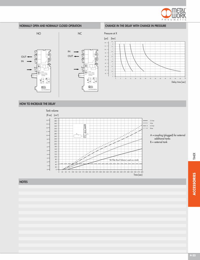
The Timer is part of Metal Work range of logic elements, which also includes OR, AND, NOT, yEs, MEMORy.The value of the signal output delay is set by rotating a knob. It can work both as 3/2 NC and 3/2 NO, depending on whether feeding is through port “a“ or port “b”.The maximum delay time can be increased by unscrewing a plug and connecting the port to an external auxiliary tank.• Adaptor for Ω bar (DIN EN 50022) integrated in the body.• Pressure indicator via an orange pin• Pipe clamping system using Ø 4 (Ø 5/32) built-in push-on fittings.
TECHNICAL DATATemperature range °Fvalve coupling mmPressure range psiNominal diameter inFlow rate at 6 bar (0.6 MPa, 87 psi) ΔP 1 bar (0.1 MPa, 14.5 psi) Nl/min scfmDelay setting range ssignal shutoff time sRepeatability sFluid OperatingRepositioningInstallationAssembly
MATERIALSBodyInternal partsGasketsspring
14 to + 140Push-in fitting for Ø 4 pipe (Ø 5/32)
36.3 to 1160.106100 3.53
From 0 to 30, at 87 psi< 0.1± 0.4
Filtered, lubricated or unlubricated compressed air. If used, must be continuousBy compressed air
By mechanical springIn any direction
On Ω bar (DIN EN 50022) size 35 x 7 o 35 x 15 mm - Wall mounting using Ø 0.165 holes
Anodised aluminium / TechnopolymerBrass / Technopolymer
NBRspring steel
Code DescriptionW3604000006 Timer
TIMERTIM
ER
4-35
ACC
ESSO
RIES
NORMALLY OPEN AND NORMALLY CLOSED OPERATION CHANGE IN THE DELAY WITH CHANGE IN PRESSURE
NOTES
HOW TO INCREASE THE DELAY
NO NC Pressure at x
Delay time [sec]
Tank volume
Time [sec]
A = coupling (plugged) for external additional tanks B = external tank
Bit Filter Bowl volume ( used as a tank) TIMER
[bar] [psi]
[cm3][fl oz]

4-36
ACC
ESSO
RIES
SILENCER MW SC
SILENCER MW SCQ
SILENCER MW SE
HIGH-CAPACITY SILENCER MW SL
SILENCER MW STT
SILENCER MW SFE
Code A B F LMaterials: W0970530001 M5 0.23 0.18 0.39Nickel-plated brass W0970530002 BsPP 1/8 0.47 0.23 0.59sintered nickel-plated bronze W0970530003 BsPP 1/4 0.60 0.26 0.75
W0970530004 BsPP 3/8 0.75 0.33 1.12W0970530005 BsPP 1/2 0.90 0.34 1.30
Features: W0970530006 BsPP 3/4 1.14 0.43 1.60Pmax: 174 psi W0970530007 BsPP 1 1.42 0.45 1.99Temp.: from 14° to 176 °F
Code A B F L CHMaterials: W0970530012 BsPP 1/8 0.47 0.23 0.59 0.28 (7 mm)Nickel-plated brass W0970530013 BsPP 1/4 0.60 0.29 0.75 0.31 (8 mm)sintered nickel-plated bronze W0970530014 BsPP 3/8 0.75 0.33 1.15 0.39 (10 mm)
W0970530015 BsPP 1/2 0.90 0.35 1.24 0.55 (14 mm)W0970530016 BsPP 3/4 1.14 0.39 1.63 0.67 (17 mm)
Features: W0970530017 BsPP 1 1.42 0.47 2.01 0.90 (23 mm)Pmax: 174 psiTemp.: from 14° to 176 °F
Code AW0970530021U M5W0970530020U M7W0970530022U 1/8 NPTW0970530023U 1/4 NPTW0970530024U 3/8 NPTW0970530025U 1/2 NPTW0970530026U 3/4 NPTW0970530027U 1 NPT
Code A B F L CHMaterials: W0970530036 BsPP 3/4 1.45 0.47 8.46 1.97 (50 mm)Nickel-plated brass W0970530037 BsPP 1 1.45 0.47 8.46 1.97 (50 mm)sintered nickel-plated bronze W0970530038 BsPP 1 1/4 1.45 0.60 8.46 1.97 (50 mm)
W0970530039 BsPP 1 1/2 1.45 0.60 8.46 1.97 (50 mm)W0970530040 BsPP 2 1.45 0.67 8.66 2.56 (60 mm)
Features:Pmax: 174 psiTemp.: from 14° to 176 °F
Code A B F L CMaterials: W0970530042 BsPP 1/8 0.37 0.25 0.23 0.08Nickel-plated brass W0970530043 BsPP 1/4 0.49 0.23 0.27 0.06sintered nickel-plated bronze W0970530044 BsPP 3/8 0.63 0.29 0.33 0.06
W0970530045 BsPP 1/2 0.80 0.39 0.38 0.10W0970530046 BsPP 3/4 1.02 0.43 0.47 0.06
Features: W0970530047 BsPP 1 1.30 0.51 0.43 –Pmax: 174 psiTemp.: from 14° to 176 °F
Code AW0970530051U M5W0970530052U 1/8 NPTW0970530053U 1/4 NPTW0970530054U 3/8 NPTW0970530055U 1/2 NPTW0970530056U 3/4 NPTW0970530057U 1 NPT
SILENCERS sI
LEN
CERs

4-37
ACC
ESSO
RIES
DYNAMIC SILENCER MW SPL
SILENCER MW SPL-F
SILENCED EXHAUST REGULATOR MW SVE
SILENCED EXHAUST REGULATOR MW SVL
EXHAUST REGULATOR MW DSN
EXHAUST REGULATOR MW DSE
Code AW0970530062U 1/8 NPTW0970530063U 1/4 NPTW0970530064U 3/8 NPTW0970530065U 1/2 NPTW0970530066U 3/4 NPTW0970530067U 1 NPT
Code AW0970530072U 1/8 NPTW0970530073U 1/4 NPTW0970530074U 3/8 NPTW0970530075U 1/2 NPT
Code A F L CHMaterials: W0970520001 BsPP 1/8 0.26 0.75 - 0.90 0.81 (13 mm)Nickel-plated brass W0970520002 BsPP 1/4 0.30 0.82 - 0.96 0.59 (15 mm)sintered nickel-plated bronze W0970520003 BsPP 3/8 0.38 0.92 - 1.16 7/8 (22 mm)stainless steel spring W0970520004 BsPP 1/2 0.41 0.90 - 1.10 7/8 (22 mm)
W0970520005 BsPP 3/4 0.47 1.14 - 1.38 1.18 (30 mm)Features: W0970520006 BsPP 1 0.54 1.06 - 1.34 1.41 (36 mm)Pmax: 174 psiTemp.: from 14° to 176 °F
Code AW0970520010U M5W0970520011U BsPP 1/8W0970520012U BsPP 1/4W0970520013U BsPP 3/8W0970520014U BsPP 1/2W0970520015U BsPP 3/4W0970520016U BsPP 1
Code A B CH CH1Materials: W0970520021 BsPP 1/8 BsPP 1/8 0.47 (12 mm) 0.47 (12 mm)Nickel-plated brass W0970520022 BsPP 1/4 BsPP 1/8 0.55 (14 mm) 5/8 (16 mm)
W0970520023 BsPP 3/8 BsPP 1/4 3/4 (19 mm) 0.67 (17 mm)W0970520024 BsPP 1/2 BsPP 1/4 0.94 (24 mm) 7/8 (22 mm)
Features:Pmax: 174 psiTemp.: from 14° to 176 °F
Code A F L CHMaterials: W0970520031 BsPP 1/8 0.29 0.66 - 0.79 0.55 (14 mm)Nickel-plated brass W0970520032 BsPP 1/4 0.39 0.85 - 1.14 3/4 (17 mm)
Features:Pmax: 174 psiTemp.: from 14° to 176 °F
sILE
NCE
Rs

4-38
ACC
ESSO
RIES
FLOW CHARTS
sILENCER MW sC
sILENCER MW sCQ
sILE
NCE
Rs
sILENCER MW sTT

4-39
ACC
ESSO
RIES
sILENCER MW sPL-F
sILENCER MW svE
NOISE ABATEMENT
Reduction of the noise that you obtain mounting a silencer on a compressed air exhaust, measured by feeding at 72.5 psi, at a distance of 39.4 inch with 45° angle to the axis of the silencer (for sFE model at 90° in order to avoid the direct jet).
Middle values in the sizes.MW sC - 35 DbMW sCQ - 35 DbMW sE - 28 DbMW sTT - 32 DbMW sFE - 30 DbMW sPL - 30 DbMW sPL-F - 35 DbMW svE - 25 DbMW svL - 25 Db
FLOW CHARTS
sILE
NCE
Rs