Embed Size (px)
Citation preview

8/14/2019 ACAD Elevation Procedures
http://slidepdf.com/reader/full/acad-elevation-procedures 1/14
Mr. Tornegard 2007-2008
Architectural Drawing I Hopewell Valley Central High School
ACAD Elevation Design Procedures
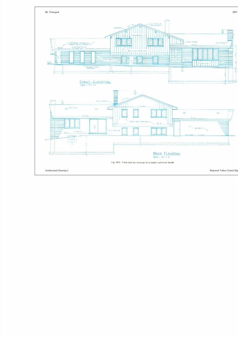
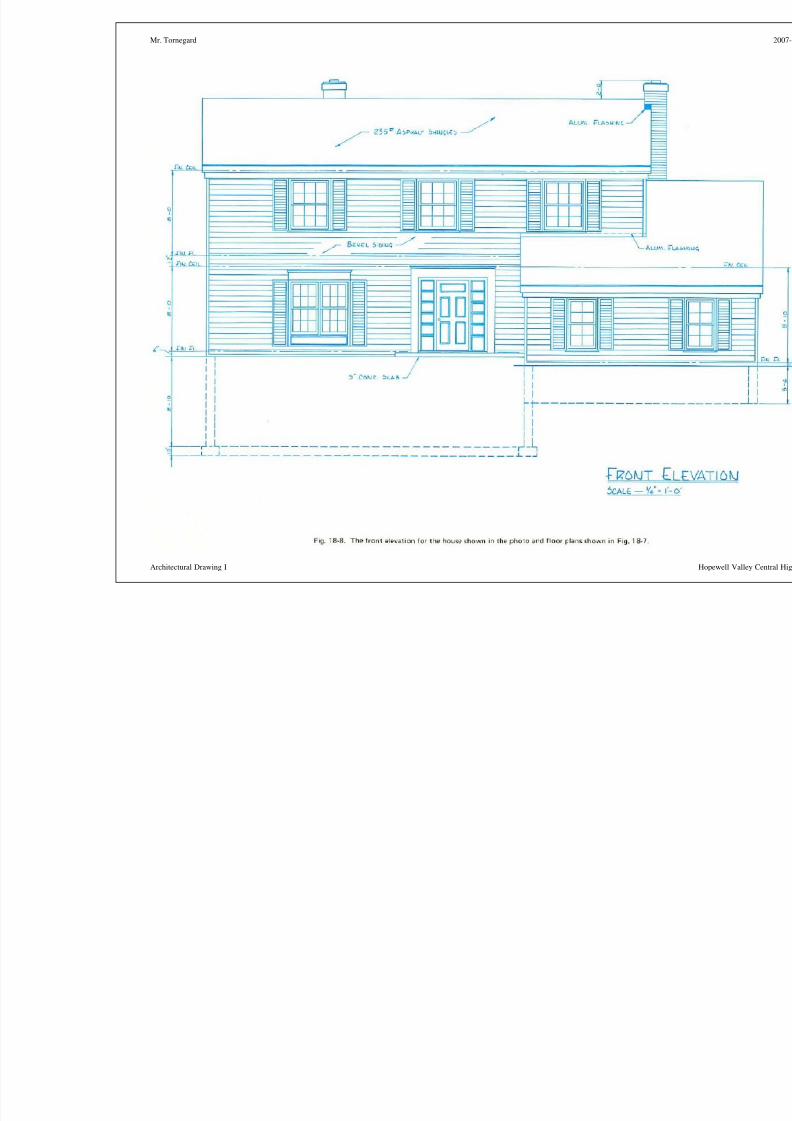
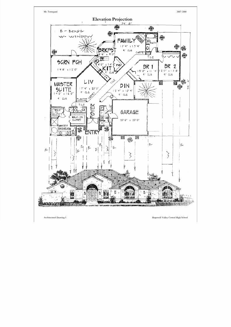
Background: An elevation drawing is an orthographic projection (drawing) that shows one side of abuilding. Details for each elevation (view) are projected down from each floor plan and over from the wallsection. The purpose of an elevation drawing is to show the finished appearance of a given side of thebuilding and furnish vertical height dimensions. They also indicate exterior finish materials and designs.Each elevation view is identified as to a particular side of the building. Commonly they are referred to asleft, right, front, and back. Sometimes, (not used in this class) they are referred too based on theirorientation (i.e. north, south, east, and west). The reference point for all elevation drawings is the gradeline. If components (i.e. foundation) lie below the grade (ground) line they are drawn with dotted lines. Inorder to complete the elevation drawings, you will have to have a complete floor plan and wall sectiondrawing completed full size in AutoCAD.
Procedure:1) Open and save a new file called Wall_Section.dwg. Use the acad.dwt template.2) Set the drawing units to Architectural3) Create the following layers: First Floor Plan; Second Floor Plan; Wall Section; and F Elevation; B
Elevation; L Elevation; R Elevation. Each of the elevation layers will be for the front, back, left, andright elevation drawings. You can use different colors to organize them if you want.
4) Open your first floor plan and copy the floor plan. Paste it into the Wall Section file on the First FloorPlan layer.
5) Open the second floor plan and copy and paste it onto the Second floor plan layer in the wall sectionfile.Note: Make sure that the floor plans are properly aligned on top of each other. All exterior wallsshould align as well as windows.
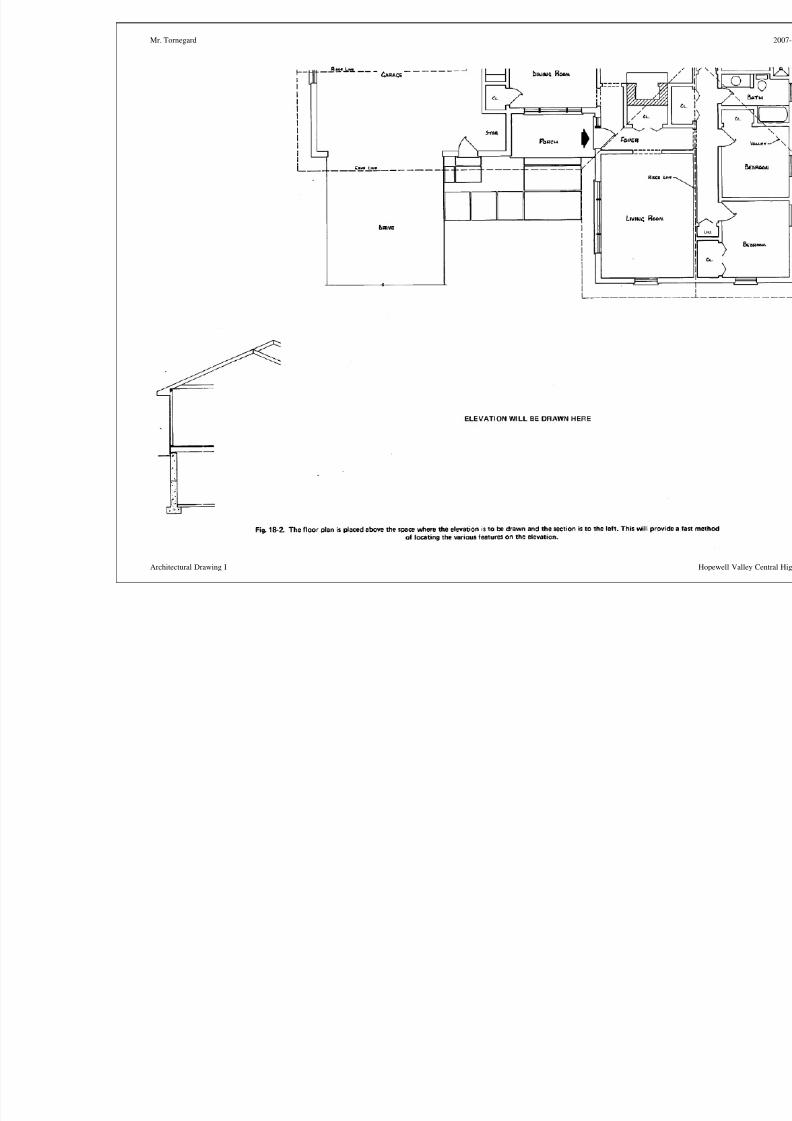
6) Open the wall section drawing and copy and paste it into the elevation drawing onto the wall sectionlayer. Align it so that is to the left of the floor plan and below it (see example below).
7) Begin with the front of the home. Make sure that your elevation is pasted in the correct location in
relation to the wall that you are representing (see sample below).8) Make sure that the first floor plan and wall section are visible, and the second floor is hidden by turning off its light bulb in the layer drop down menu.Note: You may activate the 2nd floor layer to transfer any windows or doors that are different than thefirst floor.
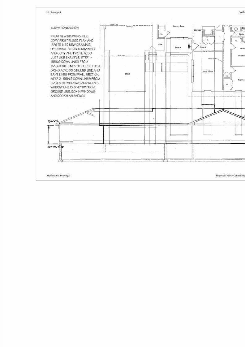
9) Begin your drawing by projecting a ground line horizontally from the wall section to the right. Makesure that it extends past the opposite edge of the floor plan.
10) Project eave lines and ridge lines over from the wall section.11) Project major lines down from the outside of the house. They should intersect the ground line.12) Bring down lines for the edges of windows and doors from the floor plan.13) Draw a horizontal window and door lines that is 8’6” up from the ground for the first floor and 18’ for
the second floor. These lines will be the top for all windows on the first floor and second floors.14) Go to the windowsymbols.com website and download the elevation view for each of the windows that
you selected. Paste them in the appropriate place on your elevation drawing.15) See the Window_Door_detail.pdf file on the shared drive and add in the details and trim for your
exterior doors.16) Use the lines that you projected for the roof to complete the roof. Layout the correct overhangs for
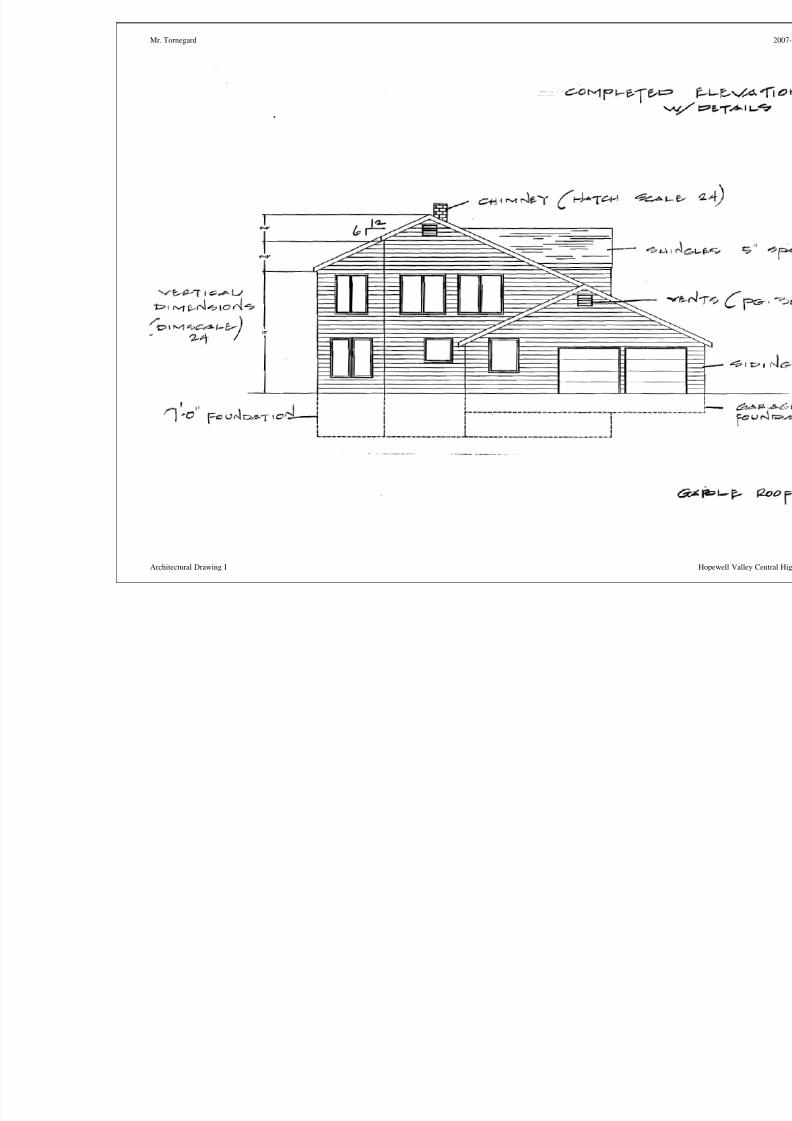
eaves and gable ends. Overhangs are 12” for the first floor and 6” for the second. Fascias are 8 inches wide. Add the roof slope symbol to indicate the slope for your roof (see the examples for details).
17) Add porches and / or decks. Top of porches and decks are 6” below door line, or 1’6” from groundline. Steps are 6” high. Railings are 3’ tall.
8/14/2019 ACAD Elevation Procedures
http://slidepdf.com/reader/full/acad-elevation-procedures 2/14
Mr. Tornegard 2007-2008
Architectural Drawing I Hopewell Valley Central High School
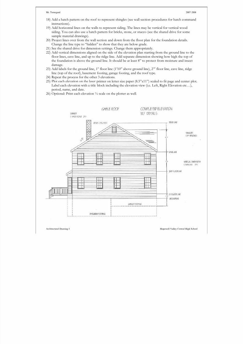
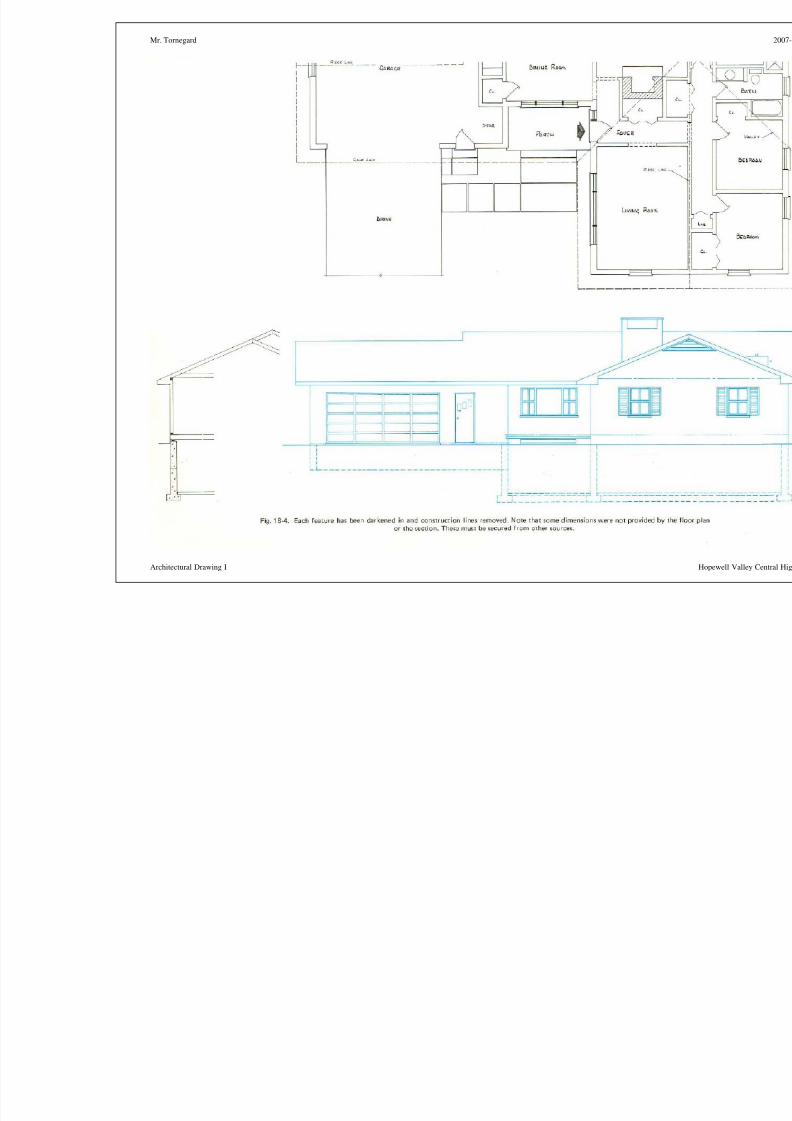
18) Add a hatch pattern on the roof to represent shingles (see wall section procedures for hatch commandinstructions).
19) Add horizontal lines on the walls to represent siding. The lines may be vertical for vertical woodsiding. You can also use a hatch pattern for bricks, stone, or stucco (see the shared drive for somesample material drawings).
20) Project lines over from the wall section and down from the floor plan for the foundation details.Change the line type to “hidden” to show that they are below grade.
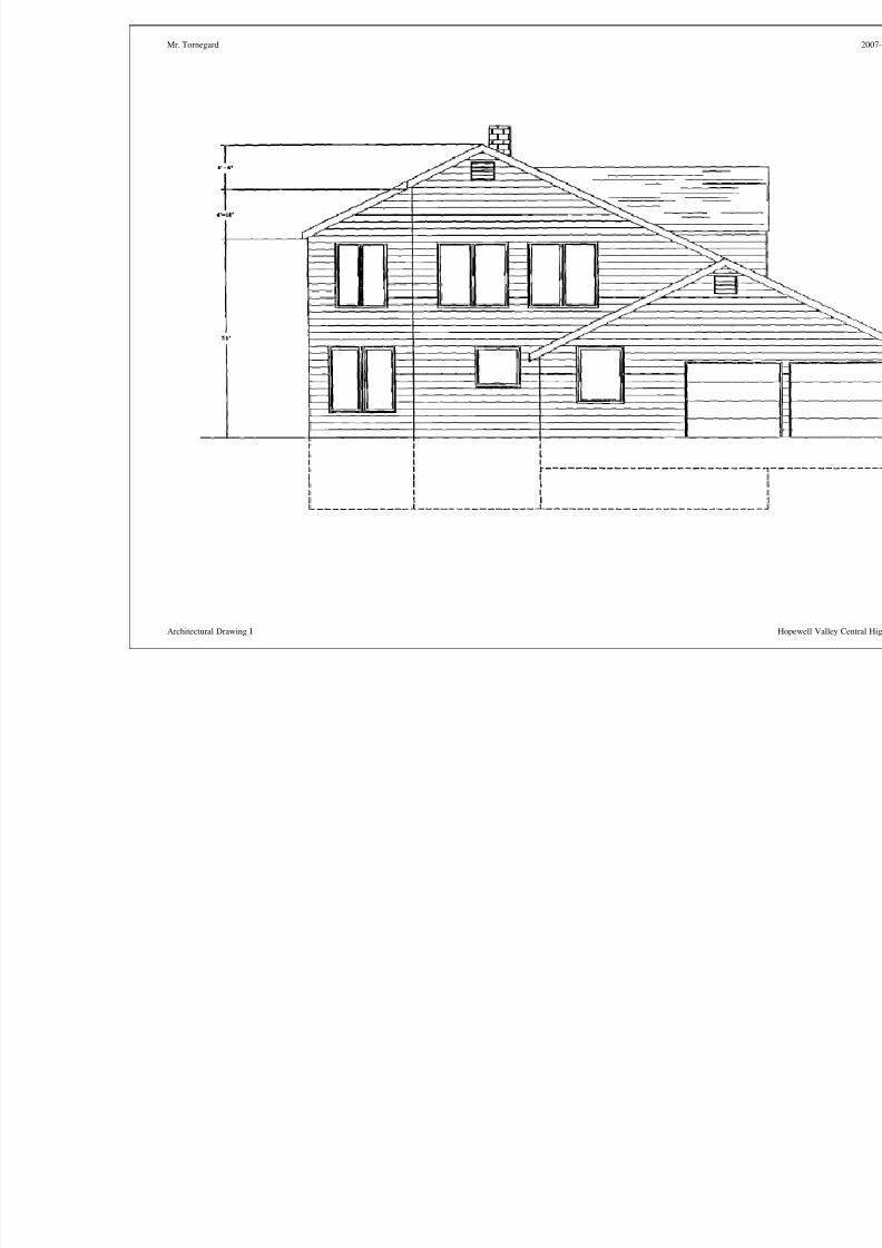
21) See the shared drive for dimension settings. Change them appropriately.22) Add vertical dimensions aligned on the side of the elevation plan starting from the ground line to the
floor lines, eave line, and up to the ridge line. Add separate dimension showing how high the top of the foundation is above the ground line. It should be at least 8” to protect from moisture and insectdamage.
23) Add labels for the ground line, 1st floor line (1’10” above ground line), 2nd floor line, eave line, ridgeline (top of the roof), basement footing, garage footing, and the roof type.
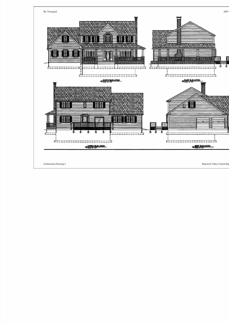
24) Repeat the process for the other 3 elevations.25) Plot each elevation on the laser printer on letter size paper (8.5”x11”) scaled to fit page and center plot.
Label each elevation with a title block including the elevation view (i.e. Left, Right Elevation etc…),period, name, and date.
26) Optional: Print each elevation ¼ scale on the plotter as well.
8/14/2019 ACAD Elevation Procedures
http://slidepdf.com/reader/full/acad-elevation-procedures 3/14
Mr. Tornegard
Architectural Drawing I

8/14/2019 ACAD Elevation Procedures
http://slidepdf.com/reader/full/acad-elevation-procedures 4/14
8/14/2019 ACAD Elevation Procedures
http://slidepdf.com/reader/full/acad-elevation-procedures 5/14
Mr. Tornegard
Architectural Drawing I

8/14/2019 ACAD Elevation Procedures
http://slidepdf.com/reader/full/acad-elevation-procedures 6/14
Mr. Tornegard
Architectural Drawing I
8/14/2019 ACAD Elevation Procedures
http://slidepdf.com/reader/full/acad-elevation-procedures 7/14
Mr. Tornegard
Architectural Drawing I

8/14/2019 ACAD Elevation Procedures
http://slidepdf.com/reader/full/acad-elevation-procedures 8/14
Mr. Tornegard
Architectural Drawing I
8/14/2019 ACAD Elevation Procedures
http://slidepdf.com/reader/full/acad-elevation-procedures 9/14
Mr. Tornegard
Architectural Drawing I
8/14/2019 ACAD Elevation Procedures
http://slidepdf.com/reader/full/acad-elevation-procedures 10/14
Mr. Tornegard
Architectural Drawing I
8/14/2019 ACAD Elevation Procedures
http://slidepdf.com/reader/full/acad-elevation-procedures 11/14
Mr. Tornegard
Architectural Drawing I
8/14/2019 ACAD Elevation Procedures
http://slidepdf.com/reader/full/acad-elevation-procedures 12/14
Mr. Tornegard
Architectural Drawing I
8/14/2019 ACAD Elevation Procedures
http://slidepdf.com/reader/full/acad-elevation-procedures 13/14
Mr. Tornegard
Architectural Drawing I
8/14/2019 ACAD Elevation Procedures
http://slidepdf.com/reader/full/acad-elevation-procedures 14/14
Mr. Tornegard 2007-2008
Architectural Drawing I Hopewell Valley Central High School
Elevation Projection