Embed Size (px)
Citation preview
AC Transit Real-Time Bus CAD/AVL Replacement Concept of Operations (Conops)
April 2013
S U B M I T T E D T O
Alameda County Transit
S U B M I T T E D BY
IBI GroupCambridge Systematics, Inc.

Table of Contents
Executive Summary ...........................................................................................1
Introduction ............................................................................................................................... 1
Current Environment ................................................................................................................. 1
Proposed Concept .................................................................................................................... 2
Operational Impacts .................................................................................................................. 3
How to Use This Document ...............................................................................6
Organization of the Document ................................................................................................... 6
Who Should Read This ConOps? .............................................................................................. 6
Purpose of the ConOps ............................................................................................................. 7
Keeping the ConOps Current .................................................................................................... 7
Project Background ...........................................................................................8
Project Scope ........................................................................................................................... 8
Project Drivers ........................................................................................................................... 8
Project Purpose .................................................................................................9
Summary of Current Environment ....................................................................10
Operational Units ......................................................................................................................10
System Units ............................................................................................................................12
Operational Scenarios ..............................................................................................................16
Operational Needs ...........................................................................................19
Proposed Operational Concept ........................................................................21
Summary of Operational Impacts .....................................................................22
Table of Contents
Operational Unit Impacts ......................................................................................................... 22
System Unit Impacts ................................................................................................................23
Scenario Impacts .....................................................................................................................25
Appendices
IBI GROUP AC TRANSIT – CAD/AVL REPLACEMENT CONCEPT OF OPERATIONS
1APRIL 2013
1. Executive Summary
1.1. Introduction
1.1.1. ScopeAC Transit’s existing computer aided dispatching and automated vehicle location (CAD/AVL) system is over ten years old and the system’s end of life is imminent. While the existing system has served the Agency adequately over many years, the current servers and central software are aging, and the existing CAD system is reaching the end of its service life. In 2014, the system warranty expires and the system will no longer be supported by the vendor, thereby exposing critical operations to an increased risk of failure.
The Agency’s existing voice and data radio communications system is a Motorola “Transit Trunked” system that provides integrated voice and data radio communications. The OrbCad 2000 CAD/AVL central software interfaces with the Motorola Centracom ELITE consoles. This enables controllers to manage voice and data radio communication via radio base stations between revenue vehicles and the Operations Control Center (OCC) located in Emeryville, California. The communications system has a single point of failure with no redundancy, thus exposing the agency to catastrophic failure if the system were to crash.
1.1.2. NeedsThe operational needs were identifi ed through a needs assessment with key project stakeholders, along with analysis of the Current Operating Environment (Section ) and the CAD/AVL Project Purpose and Objectives (Section 4). These needs represent the necessary changes from today’s operations to achieve the goals set out in the project purpose. The key elements that have led to development of the operational needs required to meet the project goals are:
• Better Service Management by better regulating service.
• Better Asset Performance by enhancing the agency’s whole life-cycle asset management capability.
• Better Customer Information through improved accuracy, quality, fl exibility, and timeliness of information gathering and dissemination.
• Better Operational Plans and Schedules through improved, open, and fl exible analysis of historic performance data.
1.1.3. PurposeThe purpose of this Concept of Operations (ConOps) is to identify the current operating environment with respect to the CAD/AVL system and document potential impacts that may result by upgrading to a newer, more robust system.
1.2. Current EnvironmentAC Transit’s existing computer aided dispatching and automated vehicle location (CAD/AVL) system is an ACS/Xerox (previously Orbital TMS) system called OrbCad 2000, version 5.023. CAD/AVL systems provide schedule adherence information for drivers (Operators); real-time vehicle location and schedule adherence information at dispatch (Controllers); and automatic data collection of the date, time, and location for many onboard events. Messages from Operators and exception reports are automatically generated by the onboard system and sent via data radio back to the Operations Control Center (OCC). The combined system features provide an effective means for Operators and Controllers to share information on the current service status being delivered to the public.
The overall CAD/AVL system is best thought of in terms of operational units (those who operate within the system) and systems units (the elements that make up the physical system).
IBI GROUP AC TRANSIT – CAD/AVL REPLACEMENT CONCEPT OF OPERATIONS
2 APRIL 2013
The operational units include:
• Window Dispatch – Ensures the on-time dispatching and return of vehicles for revenue service, monitors; the scheduled crewing of vehicles; coordinates crewing and dispatching coverage issues with central and fi eld operations; updates reports of all crew and fl eet vehicle movements at AC Transit properties; coordinates with fi eld deployed personnel, and coordinates with maintenance operations when necessary.
• Maintenance – Carries out scheduled and unscheduled inspection and maintenance of vehicles and associated systems through coordination with the Controllers, Window Dispatch, Road Supervisors and other AC Transit entities.
• Road Supervisors – Support service through fi eld-deployed Road Supervisors who support the resolution of disrupted and degraded service incidents; coordinate with Controllers, Window Dispatch, and Maintenance systems and personnel, as well as vehicle crew, the general public, and emergency services such as fi re and police.
• Bus Operator – Primary fi eld end user of the onboard system; coordinates with Controllers and Road Supervisors to operate the transit vehicle and maintain operations; transmits information and receives instructions from Controllers for degraded service including incidents, detours and other service corrections; follows onboard instructions to maintain schedule adherence.
• Controllers – Located at the OCC, Central command and control authority for all bus service delivered by AC Transit; oversee the smooth delivery of service through coordination of fi eld and central personnel and systems, as well as with external systems such as traffi c, weather, and emergency services.
Examples of systems units include:
• Central Systems – These centrally located systems include NextBus, OrbCad, and AC Transit’s Enterprise Database, strategically used by operations personnel to build situational awareness and communicate in the process of their duties.
• Communications – Integrated voice and data radio system that supports transit operations and communications between OCC, Road Supervisors, and the transit vehicles.
• Customer Information Systems – These systems are provided through third party applications and centers. NextBus provides transit customers with real-time transit arrival predictions online and in selected transit stops and centers. It also provides information for the regional 511 website. AC Transit also contracts out to a call center to answer questions from transit customers.
• Service Planning – The service planning and scheduling processes are supported by fi eld data from on and off-board systems, both within AC Transit and externally (e.g., traffi c, weather).
• On-board Vehicle Systems – These systems are deployed on vehicles and interface with the Operator and/or CAD/AVL onboard computer system, or operate independently from the CAD/AVL onboard computer system. These include the farebox, headsign, Public Address system (PA), Automatic Vehicle Announcements (AVA), Automatic Passenger Counters (APC), silent alarm switch, and video recording system.
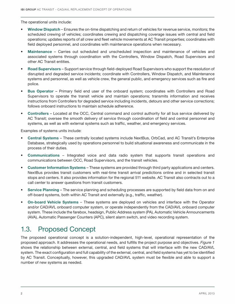
1.3. Proposed ConceptThe proposed operational concept is a solution-independent, high-level, operational representation of the proposed approach. It addresses the operational needs, and fulfi lls the project purpose and objectives. Figure 1 shows the relationship between external, central, and fi eld systems that will interface with the new CAD/AVL system. The exact confi guration and full capability of the external, central, and fi eld systems has yet to be identifi ed by AC Transit. Conceptually, however, this upgraded CAD/AVL system must be fl exible and able to support a number of new systems as needed.
IBI GROUP AC TRANSIT – CAD/AVL REPLACEMENT CONCEPT OF OPERATIONS
3APRIL 2013
1.4. Operational ImpactsThe existing operational units (e.g., Controllers, Operators) that interface with the system will not change. The new systems will create effi ciencies and facilitate the dissemination of better, more accurate information to stakeholders and transit customers. The system units will undergo slight modifi cations to create these effi ciencies. This may include streamlining processes and tools, direct center-to-center integration, and development/deployment of new applications. Detailed information on the overall operational impacts can be found in Section 8 of this document.
1.4.1. Operational Unit ImpactsRoles that each operational unit play will, in essence, remain the same; however, it’s anticipated that with the addition of more accurate information, availability of new information, and advanced features and functions, current processes and activities may change.
• Window Dispatch – Implementation of the new crew management system (Hastus) Integrated Daily Operations project will allow Window Dispatch to enter changes occurring daily in real time (e.g., changes made to vehicle and crew assignments). This will allow Controllers to have the most accurate and up to date information.
• Maintenance – Availability for remote vehicle monitoring will provide the agency with proactive monitoring of vehicle health and allow the maintenance department to troubleshoot issues remotely. Access to automated status messages from the CAD/AVL system will also facilitate better communications between the various responders about maintenance issues (Controllers, Windows Dispatch, Road Supervisors, and Maintenance.).
• Road Supervisors – The new system will help Controllers easily locate Road Supervisors to facilitate incident response. Controllers will also be able to better manage the work distribution to Road Supervisors using the new system.
• Bus Operators – With the new onboard architecture, Operators will be able to log into all systems integrated with the Vehicle Logic Unit (VLU) using a single log on. This will reduce the number of log on errors and issues.
Central System
Field Systems
Field commands
Central system
information
Field information
Central system
commands
External SystemsExternal commands
External commands
Central system information
Field information
External information
External information
New AC Transit CAD/AVL
Figure 1: The major conceptual elements exchanging information
IBI GROUP AC TRANSIT – CAD/AVL REPLACEMENT CONCEPT OF OPERATIONS
4 APRIL 2013
With the advanced automated message and support tools available to Controllers, their communications with Operators will be more clear and consistent.
• Controllers – As with Operators, Controllers will also see signifi cant changes with using a newer system. These changes will primarily center on new tools and processes to assist with daily activities, by streamlining and providing decision making support tools for actions that are currently performed and recorded manually. Controllers will have more accurate information to fulfi ll their duties, and will move from reactively to proactively managing transit service.
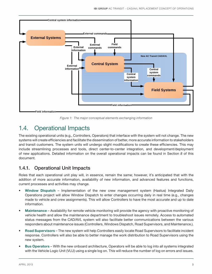
1.4.2. System Unit ImpactsThe proposed central system architecture consists of a single direct workstation interface for the System Administrator to the CAD/AVL system, which will include a direct interface with the Hastus scheduling system for provision of daily operational data. Additionally, real-time vehicle location data will be sent directly to the region’s 511 information systems for providing stop arrival predictions. Accumulated real-time data stored in the CAD/AVL system will be available through database views, using which AC Transit will copy this data into their Enterprise Database (see Figure 2).
Figure 2: Proposed System Architecture for the new CAD/AVL system
IBI GROUP AC TRANSIT – CAD/AVL REPLACEMENT CONCEPT OF OPERATIONS
5APRIL 2013
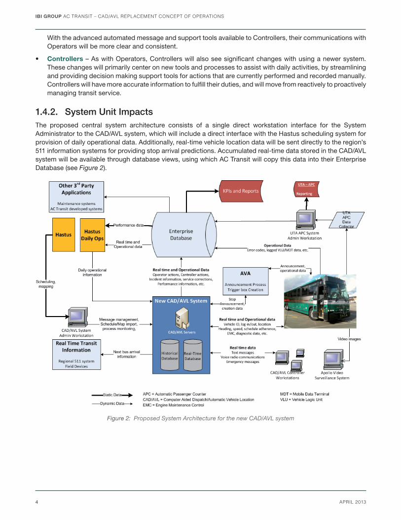
1.4.3. OnBoard Vehicle SystemsAs CAD/AVL systems have become more modular, transit agencies are realizing the benefi ts of incorporating an onboard network similar to that in an offi ce IT environment, to help future-proof vehicles. AC Transit’s future onboard system will include a mobile access router (MAR) to provide multi-path data communications between the onboard equipment and central systems and the ability to integrate such data communications access for both new and existing devices. The diagram below illustrates an example future replacement system using a MAR.
Figure 3: Future high-level onboard system architecture
IBI GROUP AC TRANSIT – CAD/AVL REPLACEMENT CONCEPT OF OPERATIONS
6 APRIL 2013
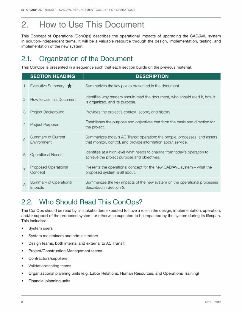
2. How to Use This DocumentThis Concept of Operations (ConOps) describes the operational impacts of upgrading the CAD/AVL system in solution-independent terms. It will be a valuable resource through the design, implementation, testing, and implementation of the new system.
2.1. Organization of the DocumentThis ConOps is presented in a sequence such that each section builds on the previous material.
SECTION HEADING DESCRIPTION
1 Executive Summary Summarizes the key points presented in the document.
2 How to Use this DocumentIdentifi es why readers should read the document, who should read it, how it
is organized, and its purpose.
3 Project Background Provides the project’s context, scope, and history.
4 Project PurposeEstablishes the purpose and objectives that form the basis and direction for
the project.
5Summary of Current
Environment
Summarizes today’s AC Transit operation: the people, processes, and assets
that monitor, control, and provide information about service.
6 Operational NeedsIdentifi es at a high level what needs to change from today’s operation to
achieve the project purpose and objectives.
7Proposed Operational
Concept
Presents the operational concept for the new CAD/AVL system – what the
proposed system is all about.
8Summary of Operational
Impacts
Summarizes the key impacts of the new system on the operational processes
described in Section 5.
2.2. Who Should Read This ConOps?The ConOps should be read by all stakeholders expected to have a role in the design, implementation, operation, and/or support of the proposed system, or otherwise expected to be impacted by the system during its lifespan. This includes:
• System users
• System maintainers and administrators
• Design teams, both internal and external to AC Transit
• Project/Construction Management teams
• Contractors/suppliers
• Validation/testing teams
• Organizational planning units (e.g. Labor Relations, Human Resources, and Operations Training)
• Financial planning units
IBI GROUP AC TRANSIT – CAD/AVL REPLACEMENT CONCEPT OF OPERATIONS
7APRIL 2013
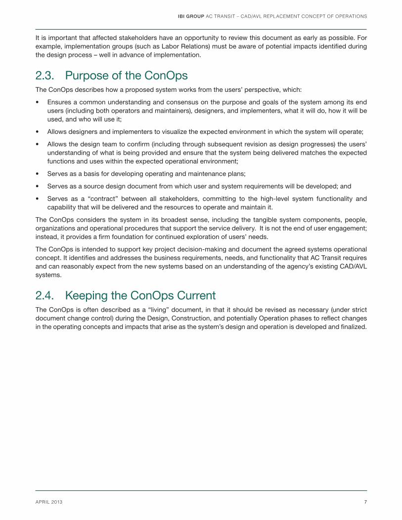
It is important that affected stakeholders have an opportunity to review this document as early as possible. For example, implementation groups (such as Labor Relations) must be aware of potential impacts identifi ed during the design process – well in advance of implementation.
2.3. Purpose of the ConOpsThe ConOps describes how a proposed system works from the users’ perspective, which:
• Ensures a common understanding and consensus on the purpose and goals of the system among its end users (including both operators and maintainers), designers, and implementers, what it will do, how it will be used, and who will use it;
• Allows designers and implementers to visualize the expected environment in which the system will operate;
• Allows the design team to confi rm (including through subsequent revision as design progresses) the users’ understanding of what is being provided and ensure that the system being delivered matches the expected functions and uses within the expected operational environment;
• Serves as a basis for developing operating and maintenance plans;
• Serves as a source design document from which user and system requirements will be developed; and
• Serves as a “contract” between all stakeholders, committing to the high-level system functionality and capability that will be delivered and the resources to operate and maintain it.
The ConOps considers the system in its broadest sense, including the tangible system components, people, organizations and operational procedures that support the service delivery. It is not the end of user engagement; instead, it provides a fi rm foundation for continued exploration of users’ needs.
The ConOps is intended to support key project decision-making and document the agreed systems operational concept. It identifi es and addresses the business requirements, needs, and functionality that AC Transit requires and can reasonably expect from the new systems based on an understanding of the agency’s existing CAD/AVL systems.
2.4. Keeping the ConOps CurrentThe ConOps is often described as a “living” document, in that it should be revised as necessary (under strict document change control) during the Design, Construction, and potentially Operation phases to refl ect changes in the operating concepts and impacts that arise as the system’s design and operation is developed and fi nalized.
IBI GROUP AC TRANSIT – CAD/AVL REPLACEMENT CONCEPT OF OPERATIONS
8 APRIL 2013
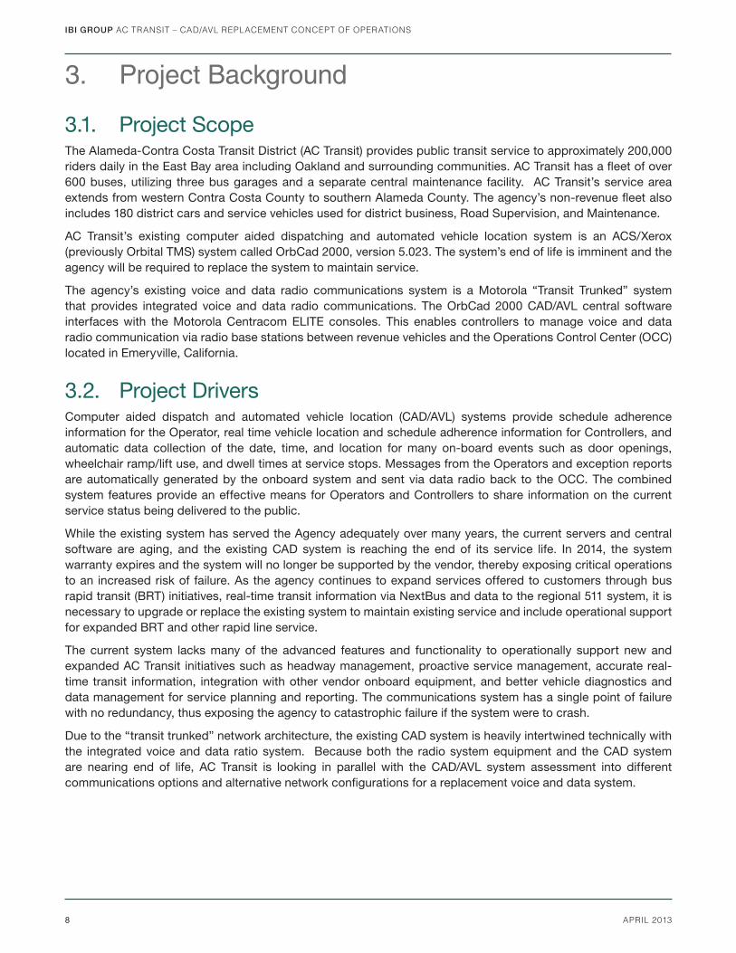
3. Project Background
3.1. Project ScopeThe Alameda-Contra Costa Transit District (AC Transit) provides public transit service to approximately 200,000 riders daily in the East Bay area including Oakland and surrounding communities. AC Transit has a fl eet of over 600 buses, utilizing three bus garages and a separate central maintenance facility. AC Transit’s service area extends from western Contra Costa County to southern Alameda County. The agency’s non-revenue fl eet also includes 180 district cars and service vehicles used for district business, Road Supervision, and Maintenance.
AC Transit’s existing computer aided dispatching and automated vehicle location system is an ACS/Xerox (previously Orbital TMS) system called OrbCad 2000, version 5.023. The system’s end of life is imminent and the agency will be required to replace the system to maintain service.
The agency’s existing voice and data radio communications system is a Motorola “Transit Trunked” system that provides integrated voice and data radio communications. The OrbCad 2000 CAD/AVL central software interfaces with the Motorola Centracom ELITE consoles. This enables controllers to manage voice and data radio communication via radio base stations between revenue vehicles and the Operations Control Center (OCC) located in Emeryville, California.
3.2. Project DriversComputer aided dispatch and automated vehicle location (CAD/AVL) systems provide schedule adherence information for the Operator, real time vehicle location and schedule adherence information for Controllers, and automatic data collection of the date, time, and location for many on-board events such as door openings, wheelchair ramp/lift use, and dwell times at service stops. Messages from the Operators and exception reports are automatically generated by the onboard system and sent via data radio back to the OCC. The combined system features provide an effective means for Operators and Controllers to share information on the current service status being delivered to the public.
While the existing system has served the Agency adequately over many years, the current servers and central software are aging, and the existing CAD system is reaching the end of its service life. In 2014, the system warranty expires and the system will no longer be supported by the vendor, thereby exposing critical operations to an increased risk of failure. As the agency continues to expand services offered to customers through bus rapid transit (BRT) initiatives, real-time transit information via NextBus and data to the regional 511 system, it is necessary to upgrade or replace the existing system to maintain existing service and include operational support for expanded BRT and other rapid line service.
The current system lacks many of the advanced features and functionality to operationally support new and expanded AC Transit initiatives such as headway management, proactive service management, accurate real-time transit information, integration with other vendor onboard equipment, and better vehicle diagnostics and data management for service planning and reporting. The communications system has a single point of failure with no redundancy, thus exposing the agency to catastrophic failure if the system were to crash.
Due to the “transit trunked” network architecture, the existing CAD system is heavily intertwined technically with the integrated voice and data ratio system. Because both the radio system equipment and the CAD system are nearing end of life, AC Transit is looking in parallel with the CAD/AVL system assessment into different communications options and alternative network confi gurations for a replacement voice and data system.
IBI GROUP AC TRANSIT – CAD/AVL REPLACEMENT CONCEPT OF OPERATIONS
9APRIL 2013
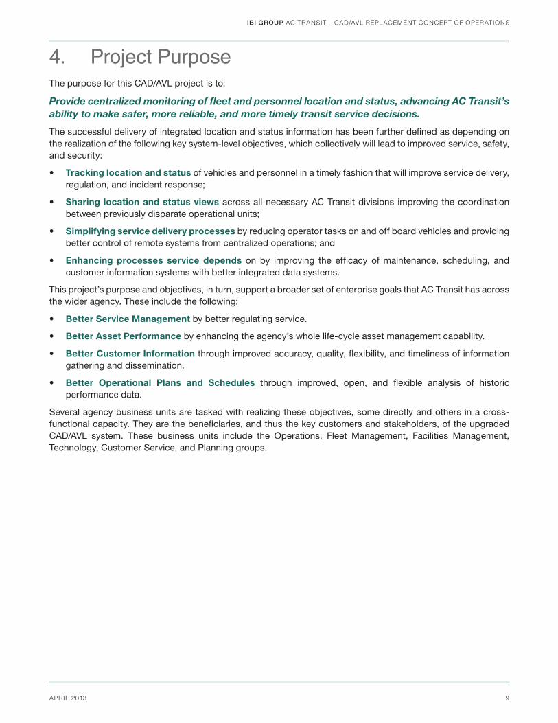
4. Project PurposeThe purpose for this CAD/AVL project is to:
Provide centralized monitoring of fl eet and personnel location and status, advancing AC Transit’s
ability to make safer, more reliable, and more timely transit service decisions.
The successful delivery of integrated location and status information has been further defi ned as depending on the realization of the following key system-level objectives, which collectively will lead to improved service, safety, and security:
• Tracking location and status of vehicles and personnel in a timely fashion that will improve service delivery, regulation, and incident response;
• Sharing location and status views across all necessary AC Transit divisions improving the coordination between previously disparate operational units;
• Simplifying service delivery processes by reducing operator tasks on and off board vehicles and providing better control of remote systems from centralized operations; and
• Enhancing processes service depends on by improving the effi cacy of maintenance, scheduling, and customer information systems with better integrated data systems.
This project’s purpose and objectives, in turn, support a broader set of enterprise goals that AC Transit has across the wider agency. These include the following:
• Better Service Management by better regulating service.
• Better Asset Performance by enhancing the agency’s whole life-cycle asset management capability.
• Better Customer Information through improved accuracy, quality, fl exibility, and timeliness of information gathering and dissemination.
• Better Operational Plans and Schedules through improved, open, and fl exible analysis of historic performance data.
Several agency business units are tasked with realizing these objectives, some directly and others in a cross-functional capacity. They are the benefi ciaries, and thus the key customers and stakeholders, of the upgraded CAD/AVL system. These business units include the Operations, Fleet Management, Facilities Management, Technology, Customer Service, and Planning groups.
IBI GROUP AC TRANSIT – CAD/AVL REPLACEMENT CONCEPT OF OPERATIONS
10 APRIL 2013
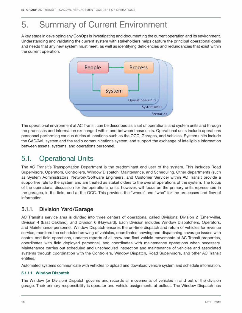
5. Summary of Current EnvironmentA key stage in developing any ConOps is investigating and documenting the current operation and its environment. Understanding and validating the current system with stakeholders helps capture the principal operational goals and needs that any new system must meet, as well as identifying defi ciencies and redundancies that exist within the current operation.
The operational environment at AC Transit can be described as a set of operational and system units and through the processes and information exchanged within and between these units. Operational units include operations personnel performing various duties at locations such as the OCC, Garages, and Vehicles. System units include the CAD/AVL system and the radio communications system, and support the exchange of intelligible information between assets, systems, and operations personnel.
5.1. Operational UnitsThe AC Transit’s Transportation Department is the predominant end user of the system. This includes Road Supervisors, Operators, Controllers, Window Dispatch, Maintenance, and Scheduling. Other departments (such as System Administrators, Network/Software Engineers, and Customer Service) within AC Transit provide a supportive role to the system and are treated as stakeholders to the overall operations of the system. The focus of the operational discussion for the operational units, however, will focus on the primary units represented in the garages, in the fi eld, and at the OCC. This provides the “where” and “who” for the processes and fl ow of information.
5.1.1. Division Yard/GarageAC Transit’s service area is divided into three centers of operations, called Divisions: Division 2 (Emeryville), Division 4 (East Oakland), and Division 6 (Hayward). Each Division includes Window Dispatchers, Operators, and Maintenance personnel. Window Dispatch ensures the on-time dispatch and return of vehicles for revenue service, monitors the scheduled crewing of vehicles, coordinates crewing and dispatching coverage issues with central and fi eld operations, updates reports of all crew and fl eet vehicle movements at AC Transit properties, coordinates with fi eld deployed personnel, and coordinates with maintenance operations when necessary. Maintenance carries out scheduled and unscheduled inspection and maintenance of vehicles and associated systems through coordination with the Controllers, Window Dispatch, Road Supervisors, and other AC Transit entities.
Automated systems communicate with vehicles to upload and download vehicle system and schedule information.
5.1.1.1. Window Dispatch
The Window (or Division) Dispatch governs and records all movements of vehicles in and out of the division garage. Their primary responsibility is operator and vehicle assignments at pullout. The Window Dispatch has
IBI GROUP AC TRANSIT – CAD/AVL REPLACEMENT CONCEPT OF OPERATIONS
11APRIL 2013
access to the crew management system (Hastus) in order to manage vehicle and operator assignments, and keep this record up to date in real-time. Throughout the day they also maintain communications with the Controllers, Road Supervisors and Maintenance to resolve degraded service or emergency issues.
5.1.1.2. Maintenance
Each Division has a maintenance department to oversee maintenance and repairs of vehicles located at that yard. Additionally, AC Transit has a Central Maintenance Facility location that serves all vehicles regardless of assigned Division. This location is staffed by maintenance managers and foremen who are responsible for maintenance duties such as the testing; repair (scheduled and unscheduled); and replacement of vehicles, vehicle parts, and on-board vehicle systems. The reporting of asset maintenance is done using the Ellipse system.
Maintenance teams at each Division coordinate closely with Window Dispatch and Controllers in the event of a vehicle failure that they need to recover from in the fi eld.
5.1.2. FieldField operations involves the roles of individuals that predominantly spend their time in the fi eld, meaning along the routes. These operational units include Road Supervisors and Operators. Field support is done through fi eld-deployed Road Supervisors who support the resolution of disrupted and degraded service incidents and coordinate with Controllers, Window Dispatch, and Maintenance, as well as Operators, the general public, and emergency services such as fi re and police. Operators spend the majority of their time on the vehicle performing service. They are the fi rst line of contact for issues and incidents occurring on the bus and are in direct contact with Controllers throughout the day.
5.1.2.1. Road Supervisor
Supervision of fi eld operations is performed by Road Supervisors deployed in the fi eld to monitor, report, and coordinate on degraded or emergency situations. They maintain constant communications with Controllers and are dispatched to fl eet locations in the event of breakdowns.
Road Supervisors maintain a manual incident logbook on board their vehicle. They can also remotely access the Apollo video surveillance system on board vehicles using secure wireless access.
5.1.2.2. Bus Operator
Operation of buses is done through Operators. They are required to check in and be assigned to their duty for the day from Window Dispatch prior to boarding a bus. When beginning their operating day from the yard, Operators are required to perform a series of vehicle checks and then log on to the vehicle before beginning their work for the day. Often interaction between the Operator and other operational units will occur throughout the operating day. Incidents, equipment defects, and other issues occurring on the vehicle are reported by the Operator through radio calls, forms, and other such means. Operators are required to refer to their standard operating procedures in response to incidents that occur while in the fi eld or during their operating day.
5.1.3. Operations Control Center (OCC)The Operations Control Center (OCC) is the central situational awareness and command center. Using the OrbCad workstation and communications systems, OCC Controllers and their supervisors maintain situational awareness of fi eld operations. They have the authority to delegate tasks to Road Supervisors and Operators to enable the smooth running of service.
5.1.3.1. Controllers
The central command and control authority for all bus service delivered by AC Transit is located at the OCC. Controllers and OCC supervisors oversee the smooth delivery of service through coordination of fi eld and central personnel and systems, as well as coordination with external systems such as traffi c, weather, and emergency services.
IBI GROUP AC TRANSIT – CAD/AVL REPLACEMENT CONCEPT OF OPERATIONS
12 APRIL 2013
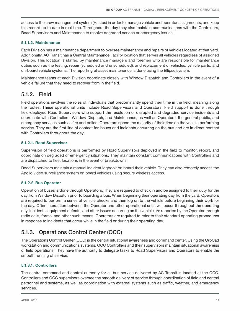
5.2. System UnitsThe existing CAD/AVL system impacts many Agency stakeholders, as well as regional partnered stakeholders. Data generated from the CAD/AVL system is transferred to the AC Transit Enterprise Database where it is used to supply several departments with information needed to run reports, research incidents and perform other necessary tasks within the agency. The CAD/AVL system also feeds (and/or is fed by) other third-party vendor systems such as: NextBus, Hastus, Ellipse, and the regional 511 website. The diagram below provides a high-level system overview of the CAD/AVL system.
Figure 4: Existing System Overview
IBI GROUP AC TRANSIT – CAD/AVL REPLACEMENT CONCEPT OF OPERATIONS
13APRIL 2013
Primary systems units include:
• Central Systems – These centrally located systems include NextBus, OrbCad,Hastus scheduling and daily operations, and the Agency’s Enterprise Database, strategically used by operations personnel to build situational awareness and communicate in the process of their duties.
• Communications – Integrated voice and data radio system that supports transit operations and communications between OCC, Road Supervisors, and the transit vehicles.
• Customer Information Systems – These systems provide ongoing customer information to travelers and include a call center, NextBus arrival predictions in the fi eld, and web information via the region’s 511 system and NextBus.
• Service Planning Systems – The agency is undergoing a signifi cant Hastus upgrade project that will replace many systems with the latest suite of Hastus solutions. This includes upgrades to the existing Hastus modules Vehicle, Crew, Crew-Opt, Minibus, GEO, Roster, ATP, Rider and Checker. The agency is also currently undergoing a larger project called HIOPS (Hastus Daily Integrated Operations) that will deploy Daily Crew, Daily Vehicle, and BID/BID Web.
• Onboard Vehicle Systems – These systems are deployed on vehicles and interface with the Operator and/or CAD/AVL on-board computer system, or operate independently from the CAD/AVL on-board computer system. These include the farebox, headsign, Public Address system, Automatic Passenger Counters, silent alarm switch, and video recording system.
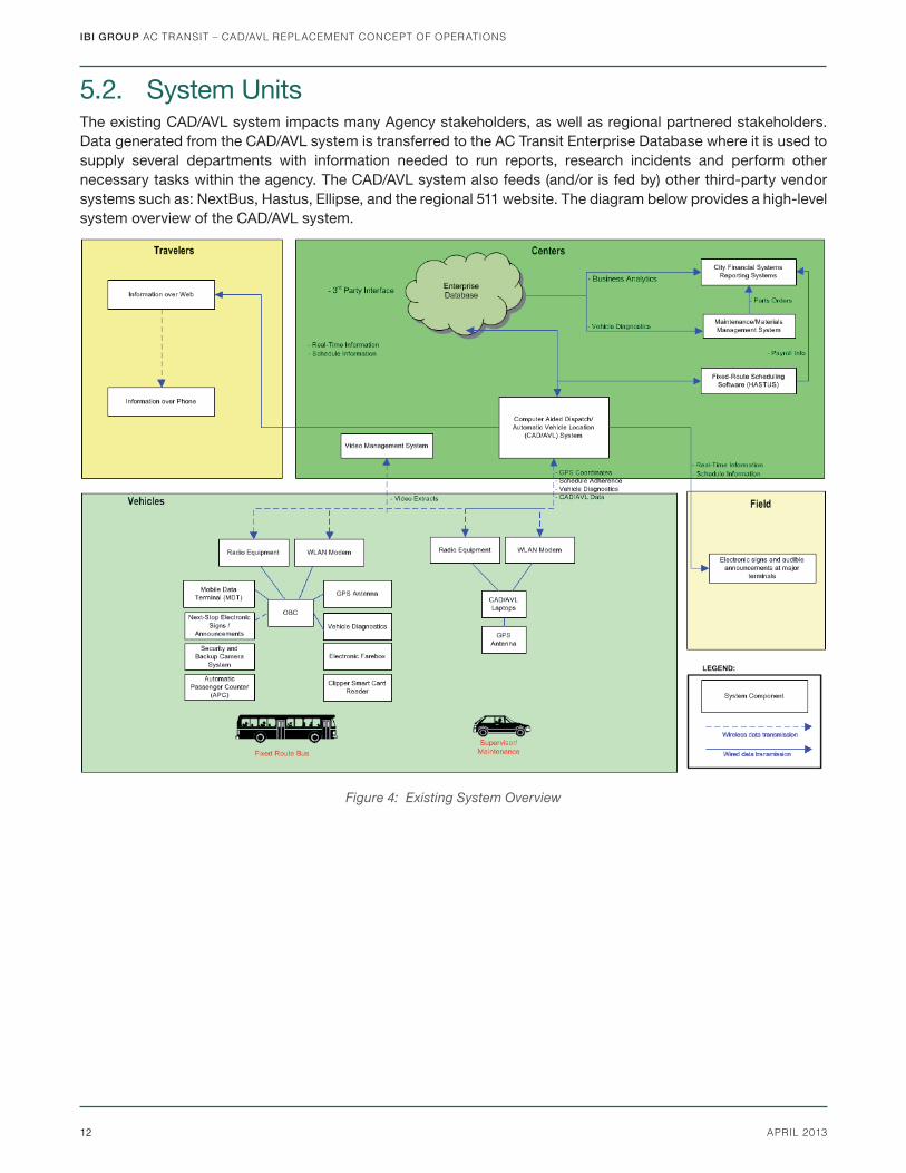
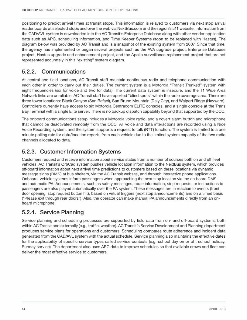
5.2.1. Central SystemsThe existing system has adequately served AC Transit; however, the system servers and software are over ten years old and are approaching their end of service life with the current vendor, putting operations at an increased risk of failure. The current system feeds into many other applications that rely on the data provided by the CAD/AVL system. This includes customer information. Currently the agency contracts with NextBus, which uses AVL
Figure 5: Existing Central Systems
IBI GROUP AC TRANSIT – CAD/AVL REPLACEMENT CONCEPT OF OPERATIONS
14 APRIL 2013
positioning to predict arrival times at transit stops. This information is relayed to customers via next stop arrival reader boards at selected stops and over the web via NextBus.com and the region’s 511 website. Information from the CAD/AVL system is downloaded into the AC Transit’s Enterprise Database along with other vendor application data such as APC, scheduling information, and Time Keeper Systems (soon to be replaced with Hastus). The diagram below was provided by AC Transit and is a snapshot of the existing system from 2007. Since that time, the agency has implemented or began several projects such as the AVA upgrade project, Enterprise Database project, Hastus upgrade and enhancement project, and the Apollo surveillance replacement project that are not represented accurately in this “existing” system diagram.
5.2.2. CommunicationsAt central and fi eld locations, AC Transit staff maintain continuous radio and telephone communication with each other in order to carry out their duties. The current system is a Motorola “Transit Trunked” system with eight frequencies (six for voice and two for data). The current data system is insecure, and the T1 Wide Area Network links are unreliable. AC Transit staff have reported “blind spots” within the radio coverage area. There are three tower locations: Black Canyon (San Rafael), San Bruno Mountain (Daly City), and Walpert Ridge (Hayward). Controllers currently have access to six Motorola Centracom ELITE consoles, and a single console at the Trans Bay Terminal with a single Elite server. There is no backup dispatch capability beyond that supported by the OCC.
The onboard communications setup includes a Motorola voice radio, and a covert alarm button and microphone that cannot be deactivated remotely from the OCC. All voice and data interactions are recorded using a Nice Voice Recording system, and the system supports a request to talk (RTT) function. The system is limited to a one minute polling rate for data/location reports from each vehicle due to the limited system capacity of the two radio channels allocated to data.
5.2.3. Customer Information SystemsCustomers request and receive information about service status from a number of sources both on and off fl eet vehicles. AC Transit’s OrbCad system pushes vehicle location information to the NextBus system, which provides off-board information about next arrival time predictions to customers based on these locations via dynamic message signs (DMS) at bus shelters, via the AC Transit website, and through interactive phone applications. Onboard, vehicle systems inform passengers when approaching the next stop location via the on-board DMS and automatic PA. Announcements, such as safety messages, route information, stop requests, or instructions to passengers are also played automatically over the PA system. These messages are in reaction to events (front door opening, stop request button hit), based on virtual triggers (next stop announcements) and on a timed basis (“Please exit through rear doors”). Also, the operator can make manual PA announcements directly from an on-board microphone.
5.2.4. Service PlanningService planning and scheduling processes are supported by fi eld data from on- and off-board systems, both within AC Transit and externally (e.g., traffi c, weather). AC Transit’s Service Development and Planning department produces service plans for operations and customers. Scheduling compares route adherence and incident data generated from the CAD/AVL system with the actual schedule. Service planning also maintains the effective dates for the applicability of specifi c service types called service contexts (e.g. school day on or off; school holiday, Sunday service). The department also uses APC data to improve schedules so that available crews and fl eet can deliver the most effective service to customers.
IBI GROUP AC TRANSIT – CAD/AVL REPLACEMENT CONCEPT OF OPERATIONS
15APRIL 2013
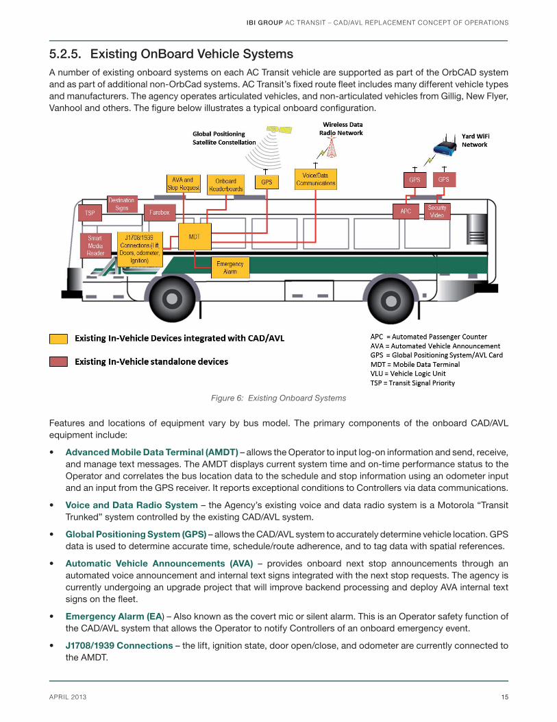
5.2.5. Existing OnBoard Vehicle Systems A number of existing onboard systems on each AC Transit vehicle are supported as part of the OrbCAD system and as part of additional non-OrbCad systems. AC Transit’s fi xed route fl eet includes many different vehicle types and manufacturers. The agency operates articulated vehicles, and non-articulated vehicles from Gillig, New Flyer, Vanhool and others. The fi gure below illustrates a typical onboard confi guration.
Features and locations of equipment vary by bus model. The primary components of the onboard CAD/AVL equipment include:
• Advanced Mobile Data Terminal (AMDT) – allows the Operator to input log-on information and send, receive, and manage text messages. The AMDT displays current system time and on-time performance status to the Operator and correlates the bus location data to the schedule and stop information using an odometer input and an input from the GPS receiver. It reports exceptional conditions to Controllers via data communications.
• Voice and Data Radio System – the Agency’s existing voice and data radio system is a Motorola “Transit Trunked” system controlled by the existing CAD/AVL system.
• Global Positioning System (GPS) – allows the CAD/AVL system to accurately determine vehicle location. GPS data is used to determine accurate time, schedule/route adherence, and to tag data with spatial references.
• Automatic Vehicle Announcements (AVA) – provides onboard next stop announcements through an automated voice announcement and internal text signs integrated with the next stop requests. The agency is currently undergoing an upgrade project that will improve backend processing and deploy AVA internal text signs on the fl eet.
• Emergency Alarm (EA) – Also known as the covert mic or silent alarm. This is an Operator safety function of the CAD/AVL system that allows the Operator to notify Controllers of an onboard emergency event.
• J1708/1939 Connections – the lift, ignition state, door open/close, and odometer are currently connected to the AMDT.
Figure 6: Existing Onboard Systems
IBI GROUP AC TRANSIT – CAD/AVL REPLACEMENT CONCEPT OF OPERATIONS
16 APRIL 2013
Other onboard equipment that does not include interfaces to the CAD/AVL system are:
• Automated Passenger Counters (APC) – located on approximately 35% of buses, APC uses infrared beams to count boarding and alighting passengers with the accumulated APC data automatically uploaded at the depot.
• Apollo Security System – allows video to be continuously captured on digital media on the bus. Up to twelve cameras are installed on each bus, depending on type. This video may be accessed wirelessly via secured access by transit security when within close proximity.
• Transit Signal Priority (TSP) – allows transit vehicles to request signal priority. Currently the TSP system is “always on” meaning the system is always requesting priority regardless of schedule adherence.
• Vehicle Destination Signs – displays the trip destination messages along AC Transit routes, as manually set by the Operator when approaching the end of each trip.
• Smart Media Fare Card Reader (Clipper) – provides customers with smart media fare payment. Due to the nature of the proprietary Clipper system, the Clipper unit is not integrated with the existing onboard equipment, nor is it expected that the unit will integrate with the new system.
• Farebox – existing cash and ticket farebox collection system is not currently integrated with the CAD/AVL system. The agency is currently in the process of upgrading their farebox to a new system (not yet determined), and it is envisioned that the new CAD/AVL system will integrate with the new farebox.
• Other Onboard Equipment – Other existing onboard equipment such as FleetWatch, Public Address system, engine control monitoring (ECM), stop request, and others are not currently integrated with the onboard system.
5.3. Operational ScenariosA complete description of all process and information exchanges between operations and systems units would be prohibitive given the complexity of the entire AC Transit system. However, a series of representative operational scenarios can be explored in order to describe the current environment. Scenarios are grouped under broad headings and are included as an appendix to this document. In general, the scenarios are broken into four core categories, with representative diagrams illustrating an operational fl ow and roles:
• Daily Operations describes a standard Pull in/out for a fi xed route bus.
• Degraded Operations examines the actions taken by Controllers to restore service impacted by a non-safety related issue.
• Emergency Operations category looks a service impacted by a critical safety related issues.
• Supporting Programs are operational units that support the smooth operation of service.
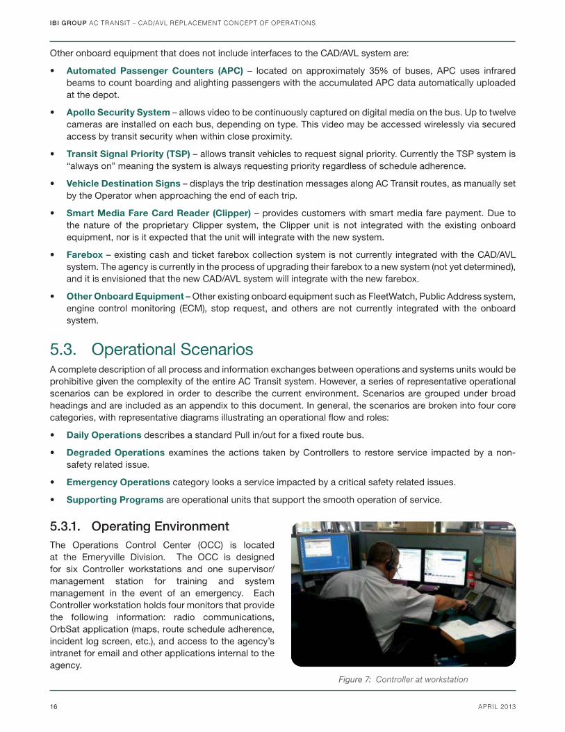
5.3.1. Operating EnvironmentThe Operations Control Center (OCC) is located at the Emeryville Division. The OCC is designed for six Controller workstations and one supervisor/management station for training and system management in the event of an emergency. Each Controller workstation holds four monitors that provide the following information: radio communications, OrbSat application (maps, route schedule adherence, incident log screen, etc.), and access to the agency’s intranet for email and other applications internal to the agency.
Figure 7: Controller at workstation

IBI GROUP AC TRANSIT – CAD/AVL REPLACEMENT CONCEPT OF OPERATIONS
17APRIL 2013
As discussed earlier, AC Transit operations are summarized in four representative categories that illustrate typical operational fl ows. Within each core category are subfl ows that provide an operational scenario to illustrate the standard fl ow of activities for the current system. Brief descriptions of the fl ows are provided below, and the process diagrams are included as Appendix A to this document.
5.3.1.1. Normal Operations
A typical day begins with “pull-out,” meaning an Operator logs onto the vehicle AMDT and various components (destination sign and farebox), cycles the wheelchair lift, performs a brake test and drives to the start of the fi rst trip. The service day generally ends when the transit vehicle pulls back into the yard and the Operator logs off the vehicle equipment. AC Transit has two end-of-day scenarios, one for the vehicle and one for the Operator. Daily operations are illustrated in the Start of Day and End of Day process fl ows.
5.3.1.2. Degraded Operations
Throughout the transit day several common situations often require some form of interaction between the OCC, Road Supervisors, and Operators. These situations, such as mechanical issues and missed or late pull-outs, can sometimes require a schedule adjustment and may require interaction between several different departments. AC Transit also uses real-time performance monitoring to adjust operations to preserve or enhance service quality. This may include schedule adherence, headway management, transfer protection, and similar techniques to maintain or improve service quality in real-time during the operating day. Flows describing these scenarios are described on the next page.
• Service Correction – This process describes actions taken at OCC to return operations to a normal, steady state following a localized disruption or irregularity in service affecting a single vehicle (e.g., running late), a single line or interlined corridor (e.g. bus bunching), or a specifi c sector of the system (e.g., impacts of a traffi c accident).
• Detour/Reroute – This scenario describes the fl ow of necessary steps to reroute transit vehicles along a route for 1) pre-planned short- and long-term events and 2) unplanned events such as traffi c incidents, blockages, and other unplanned events.
• Non-Emergency Degraded Service Correction – These are localized security incidents impacting a single location or vehicle that does not represent an immediate threat to the welfare of passengers on board (“Non-Emergency” Operator and Controller response). Examples include a violation of the AC Transit passenger Code of Conduct, such as disruptive passengers. These events have the potential to escalate to a level that threatens the Operator and/or passengers or safe operation of the vehicle, requiring an Emergency Response.
• Bus Bridge – Occasionally, Bay Area Rapid Transit (BART) requests AC Transit’s services to perform a “Bus Bridge”. This occurs when BART is unable to move between stops and requires buses to shuttle passengers from one BART station to another.
5.3.1.3. Emergency Operations
AC Transit strives to provide a safe environment for transit customers and staff and uses safety features of the existing CAD/AVL system. An emergency response for the agency generally involves medical, security or accident response that is more signifi cant than an “incident”. These scenarios are divided into two sub fl ows:
1. Bus Emergency – Bus-specifi c emergencies involve medical, security, or accident response that is more signifi cant than an “incident”. Bus Emergencies typically follow two paths, a priority request to talk (PRTT) or covert alarm activation. Issues involving PRTT allow Controllers to open two-way voice radio communications with the Operator to gather important information that can be relayed to emergency responders or Road Supervisors. If a covert alarm is triggered on the vehicle, Controllers are able to open a covert microphone to gather information about the situation. During covert alarms, one-way voice radio communications only is available so as not to alert the aggressor that someone is monitoring the situation by only being able to listen.
IBI GROUP AC TRANSIT – CAD/AVL REPLACEMENT CONCEPT OF OPERATIONS
18 APRIL 2013
2. Major Incident – These types of events pertain to signifi cant major event slowdowns such as wide area fl ooding, an earthquake, or other such events. AC Transit has standard operating procedures (SOPs) to aid and recover from unplanned major events; however, the existing CAD/AVL only provides limited functionality needed to assist the OCC with recovering or aiding during major incidents. “Recovery” is defi ned as the ability to effectively operate portions of the system (based on vehicle and roadway availability) and then bring vehicles and lines back up as available, managing headways and traveler information dissemination to support these efforts.
5.3.1.4. Supporting Processes
In addition to operational fl ows focused on the delivery of day-to-day service, supporting processes such as maintenance and scheduling also impact the OCC and Operators on a semi-regular basis. These fl ows are illustrated as Maintenance and Scheduling. The Maintenance fl ow focuses on issues affecting vehicles that are in, or are imminently entering, revenue service (pull-out) and includes detection, evaluation, remote troubleshooting, and removal of disabled vehicles from service.
Scheduling involves use of archived real-time operational data to support service planning functions including scheduling and schedule adjustments, performance monitoring, ridership analysis, and other tactical and long-range planning functions. These planning activities use data collected onboard vehicles as well as CAD/AVL data as part of a “feedback” process that supports continual system improvement and adaptation to changing circumstances. The planning function also supports pre-emptive preparation for emergency and incident scenario response, such as bus bridging.
IBI GROUP AC TRANSIT – CAD/AVL REPLACEMENT CONCEPT OF OPERATIONS
19APRIL 2013
6. Operational NeedsThis section describes a set of high-level operational needs derived based on analysis of the Current Operating Environment (Section 5) and the CAD/AVL Project Purpose and Objectives (Section 4), as well as consultation with key project stakeholders through previous needs assessment workshops (see the High Level Summary of AC Transit CAD/AVL Needs memorandum for detailed information). These operational needs represent changes necessary from today’s AC Transit operations to achieve the goal set out in the project purpose. The operational needs have been classifi ed in terms of objectives they support.
The key system requirements that have led to development of the operational needs are:
Higher Quality Location and Status Gathering – To better manage and regulate service delivery, operations, maintenance, and security staff (among others) need to know the location of all resources in the fi eld in a timely fashion. For example, AC Transit currently has limited or no capability to automatically track the location of non-revenue vehicles or fi eld staff. This can lead to unnecessary challenges for Controllers trying to assign fi eld staff to emerging situations. In addition to gathering the location of resources, gathering the status of fi eld resources or data from external interfacing systems is also key to delivering a safe and successful service. This may include integrating remote vehicle engine and transmission warnings into the Ellipse maintenance system, or associating the location of all Road Supervisors with their vehicle while in the fi eld, or collecting real-time traffi c or road-weather information from third parties. The CAD/AVL system must be fl exible and support new inputs, as needs and technology advance over time.
Timely and Accurate Location and Status Sharing – The sharing of location and status information between key operations and maintenance stakeholders is crucial to success of the bus service. Without a shared view between control and the fi eld, service delivery, safety, and maintenance decisions cannot be made in a fully coordinated and rational way. Information gathered from the fi eld or external systems would otherwise continue to be shared in a number of manual, disparate ways. AC Transit, therefore, needs an integrated, automated view at the OCC and fi eld locations. This may be presented on-screen at the desktop level, on a large-scale dynamic model board, or distributed to mobile devices in the fi eld such as a Road Supervisor’s vehicle. Additionally, alerts from incidents, for example, or critical vehicle health status data can be shared directly with maintenance and safety systems at the appropriate facility to better coordinate the agency’s response.
Simplifying Systems Integration – A key concern with current systems is the increasing complexity and number of interfacing systems both on and off-board vehicles. For example, a revenue vehicle Operator must log on and log off multiple systems at the start or end of a trip. This process is time-consuming, slow, and unreliable. To better ensure compliance with Operator log on protocols, AC Transit needs to simplify onboard operational processes with the new system. It must be easy to use by Operators through minimizing complexity at the user level. Off-board maintenance of multiple interfacing systems also requires additional cost and effort that could be alleviated with a new system. Therefore, remote control and interaction between off-board systems and those onboard also needs to be streamlined such as through an easy and intuitive way to send and delete messages and instructions from the central system to the vehicles, as well as to better integrate the Hastus personnel system with key onboard systems.
Supporting Service-dependent Processes – Beyond service operations, there will be many other benefi ts to an improved CAD/AVL system. For example, scheduling and personnel divisions can benefi t from an improved interface to the Hastus system. Service performance or post-event analysis may improve due to better tracking of vehicles and personnel to enable route and service cost-savings. Maintenance will benefi t from broader full life-cycle asset management and potentially from more complete issue logs. Security personnel may benefi t through being alerted to fi eld emergencies immediately without waiting for Controller input. AC Transit has also stated they wish to provide more accurate and reliable transit traveler information to the public. Providing customer information will require a robust interface between the new CAD/AVL system and any such in-house or external information systems.
IBI GROUP AC TRANSIT – CAD/AVL REPLACEMENT CONCEPT OF OPERATIONS
20 APRIL 2013
The Appendix B graphic maps AC Transit enterprise goals to key capabilities the new system must provide. A selection are discussed below:
Service Monitoring: To improve the ability of OCC and Road Supervisors to monitor service status through a shared current operating view, shared view of all vehicle locations, status of vehicles, the environment in which they are operating (congestion, weather, etc.), and the location of fi eld personnel.
Service Delivery: To better regulate service, and to monitor and regulate on-board systems, to improve the customer experience.
Full Life-cycle Management of Assets: With improved integrated system data, the capability to expand or improve procurement strategies; administer systems; train operations staff; track scheduled, preventative, and unscheduled maintenance; track asset data using reporting tools though historic maintenance records, service records, current service data .
Customer Information: Providing better in-vehicle information through Operator control of the automated vehicle announcement (AVA) system; the ability to remotely update onboard customer information screen and PA systems; providing better information prior to boarding by pushing additional messages from central systems out to the public domain, providing better information to the call-center; providing a direct information interface to the region’s 511 system instead of through NextBus.
Service Plans and Schedules: Improving post-event analysis through events playback and analysis of service related information with user-confi gurable reports; improving plans and schedules through better disruption and emergency planning through identifi cation of defi ciencies and ineffi ciencies in the current plans.
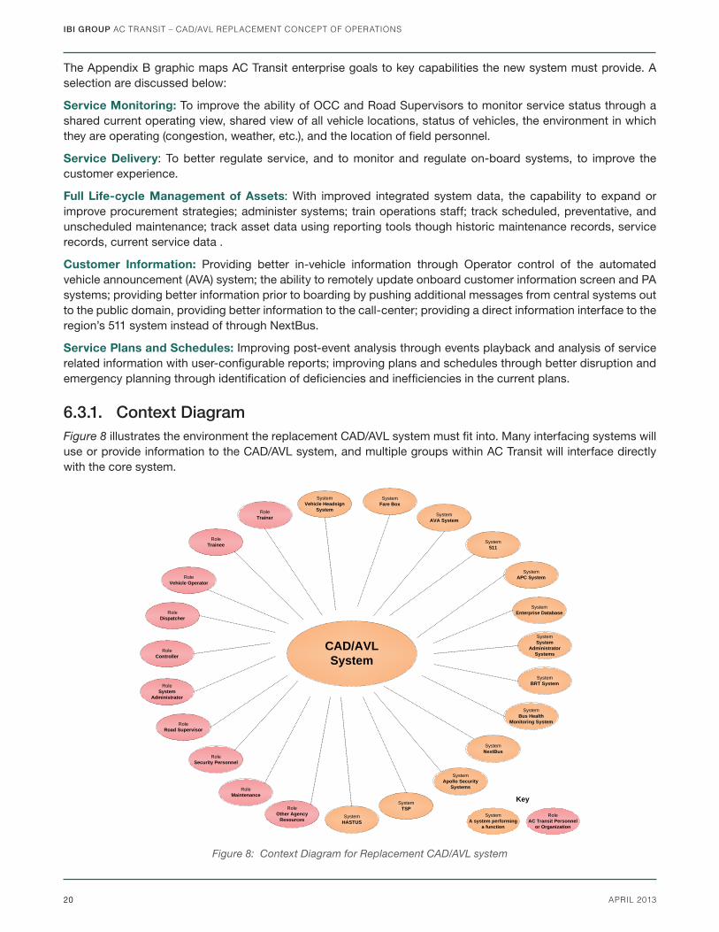
6.3.1. Context DiagramFigure 8 illustrates the environment the replacement CAD/AVL system must fi t into. Many interfacing systems will use or provide information to the CAD/AVL system, and multiple groups within AC Transit will interface directly with the core system.
RoleController
RoleSystem
Administrator
RoleRoad Supervisor
RoleSecurity Personnel
RoleMaintenance
RoleOther Agency
Resources
RoleTrainer
RoleTrainee
RoleVehicle Operator
System511
SystemNextBus
SystemSystem
Administrator Systems
SystemBRT System
SystemBus Health
Monitoring System
SystemApollo Security
Systems
SystemFare Box
SystemEnterprise Database
SystemVehicle Headsign
System
RoleDispatcher
SystemHASTUS
SystemAVA System
CAD/AVLSystem
RoleAC Transit Personnel
or Organization
SystemA system performing
a function
Key
SystemAPC System
SystemTSP
Figure 8: Context Diagram for Replacement CAD/AVL system
IBI GROUP AC TRANSIT – CAD/AVL REPLACEMENT CONCEPT OF OPERATIONS
21APRIL 2013
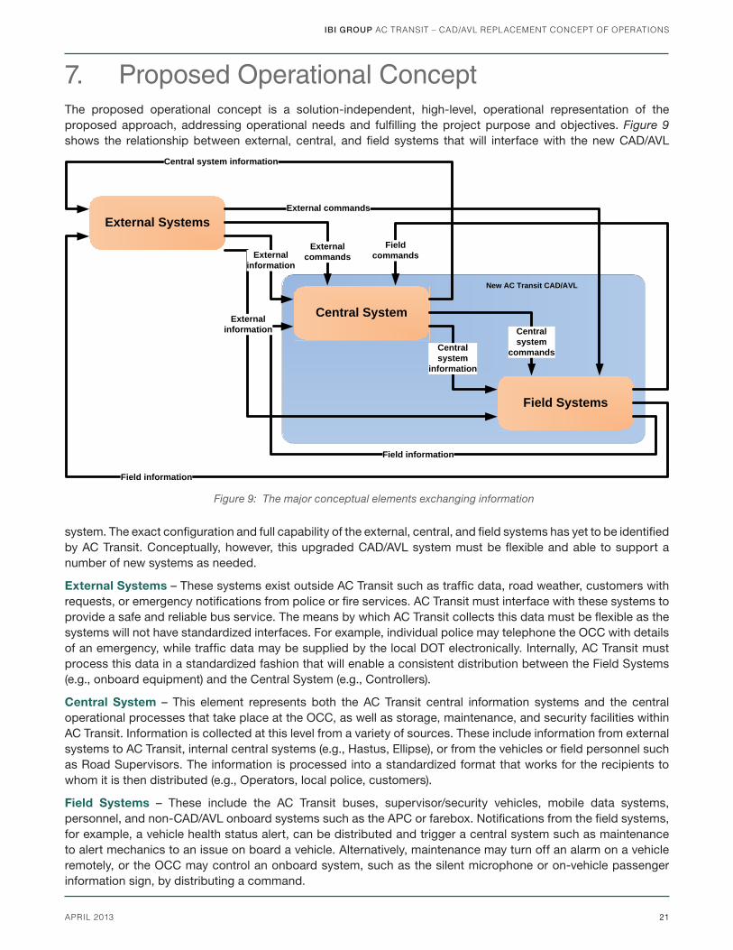
7. Proposed Operational ConceptThe proposed operational concept is a solution-independent, high-level, operational representation of the proposed approach, addressing operational needs and fulfi lling the project purpose and objectives. Figure 9 shows the relationship between external, central, and fi eld systems that will interface with the new CAD/AVL
system. The exact confi guration and full capability of the external, central, and fi eld systems has yet to be identifi ed by AC Transit. Conceptually, however, this upgraded CAD/AVL system must be fl exible and able to support a number of new systems as needed.
External Systems – These systems exist outside AC Transit such as traffi c data, road weather, customers with requests, or emergency notifi cations from police or fi re services. AC Transit must interface with these systems to provide a safe and reliable bus service. The means by which AC Transit collects this data must be fl exible as the systems will not have standardized interfaces. For example, individual police may telephone the OCC with details of an emergency, while traffi c data may be supplied by the local DOT electronically. Internally, AC Transit must process this data in a standardized fashion that will enable a consistent distribution between the Field Systems (e.g., onboard equipment) and the Central System (e.g., Controllers).
Central System – This element represents both the AC Transit central information systems and the central operational processes that take place at the OCC, as well as storage, maintenance, and security facilities within AC Transit. Information is collected at this level from a variety of sources. These include information from external systems to AC Transit, internal central systems (e.g., Hastus, Ellipse), or from the vehicles or fi eld personnel such as Road Supervisors. The information is processed into a standardized format that works for the recipients to whom it is then distributed (e.g., Operators, local police, customers).
Field Systems – These include the AC Transit buses, supervisor/security vehicles, mobile data systems, personnel, and non-CAD/AVL onboard systems such as the APC or farebox. Notifi cations from the fi eld systems, for example, a vehicle health status alert, can be distributed and trigger a central system such as maintenance to alert mechanics to an issue on board a vehicle. Alternatively, maintenance may turn off an alarm on a vehicle remotely, or the OCC may control an onboard system, such as the silent microphone or on-vehicle passenger information sign, by distributing a command.
Central System
Field Systems
Field commands
Central system
information
Field information
Central system
commands
External SystemsExternal commands
External commands
Central system information
Field information
External information
External information
New AC Transit CAD/AVL
Figure 9: The major conceptual elements exchanging information
IBI GROUP AC TRANSIT – CAD/AVL REPLACEMENT CONCEPT OF OPERATIONS
22 APRIL 2013
8. Summary of Operational ImpactsWith the Operational Concept described in Section 7 in mind, this section considers how current operations, described in Section 5, may change or be impacted. As such, this section offers an operationally focused, scenario-based view of the proposed concept.
For each process defi ned in Section 5, this section uses an annotated version of the process fl ow diagrams to identify impacts arising from the proposed Operational Concept. The analysis described in this section assumes the complete Operational Concept has been implemented. Impacts that change previous scenarios are highlighted in yellow in the fl ows.
8.1. Operational Unit Impacts
8.1.1. Division Yard/GarageWith the upgrade of the CAD/AVL system, it is not anticipated that overall responsibilities and roles in the yard will change. Many existing processes will remain the same; however tools by which these procedures are followed may change as effi ciencies are found using the replacement system.
8.1.1.1. Window Dispatch
With the new Hastus upgrade project, Window Dispatch will enter changes to Operator/vehicle assignments in real time to the new Hastus system. This information will be used to help facilitate log on using only the Operator ID.
8.1.1.2. Maintenance
With the new system it is envisioned that additional vehicle monitoring data will be available to the maintenance department remotely. This includes ECM performed over the J1708/1939 connections that will be recorded and logged by the VLU in accordance with fi ltering parameters. If one of the specifi c confi gured mechanical messages is triggered on the vehicle (e.g., Stop Engine Warning), that message will be immediately forwarded to the OCC and Maintenance. Each maintenance department will include a workstation with limited CAD AVL access, either directly from the CAD/AVL vendor or via an in-house developed application, to pull information from the agency’s Enterprise Database.
8.1.2. FieldThe roles and responsibilities for operational units in the fi eld are not anticipated to change. With deployment of new and more robust equipment on the vehicle, as well as potential laptop computers for Road Supervisors, effi ciencies in the fi eld will help ease ongoing frustrations and improve on-time performance and response times.
8.1.2.1. Road Supervisors
Deploying laptops will provide Road Supervisors with more information to assist with responding to incidents and to improve coordination with the OCC.
8.1.2.2. Operators
Deploying new onboard equipment will create a more effi cient means to perform daily duties. Operators will have a single point of log-on to streamline start of day duties and improve success for capturing end of day reporting data. Better accuracy in locations and improved voice and data communications will provide the Operator with the necessary information to improve schedule adherence and assist with planned and ad hoc service changes/corrections that may be required throughout the day. The new system should be easier to use, more accurate, and more effi cient.
IBI GROUP AC TRANSIT – CAD/AVL REPLACEMENT CONCEPT OF OPERATIONS
23APRIL 2013
8.1.3. Operations Control CenterThe OCC will undergo the most signifi cant change with deploying the new system. Although roles will not change, the newer full-featured CAD/AVL systems have moved from a responsive to proactive monitoring system. This has often mandated that agencies make a paradigm shift in the way they do business.
8.1.3.1. Controller
Controllers will be provided with new tools and more accurate information to proactively manage system-wide service. Although overall responsibilities will not change, new CAD/AVL system tools and features will automate some manual activities that Controllers actively perform with the current system. Additionally, many actions will now be recorded to provide a more accurate account of the efforts Controllers and other fi eld personnel took to maintain service. Service restoration tools, incident management tools, and other data will automatically collect and store the information such as lost service that the OCC must currently collect and calculate manually.
8.2. System Unit ImpactsThe new system will not dramatically change the overall system architecture, rather it will help streamline and simplify management of the existing system. Many newer CAD/AVL systems have built-in “watchdog” applications that continuously monitor internal processes and automate corrective actions. AC Transit has also expressed a desire for a fully redundant system with a testing and training environment, to fully test in-house developed applications and changes to the internal agency data warehouse prior to their release into the operational system. With the addition of many ongoing technology upgrades and projects, a testing environment and redundant system will reduce risk of catastrophic failure.
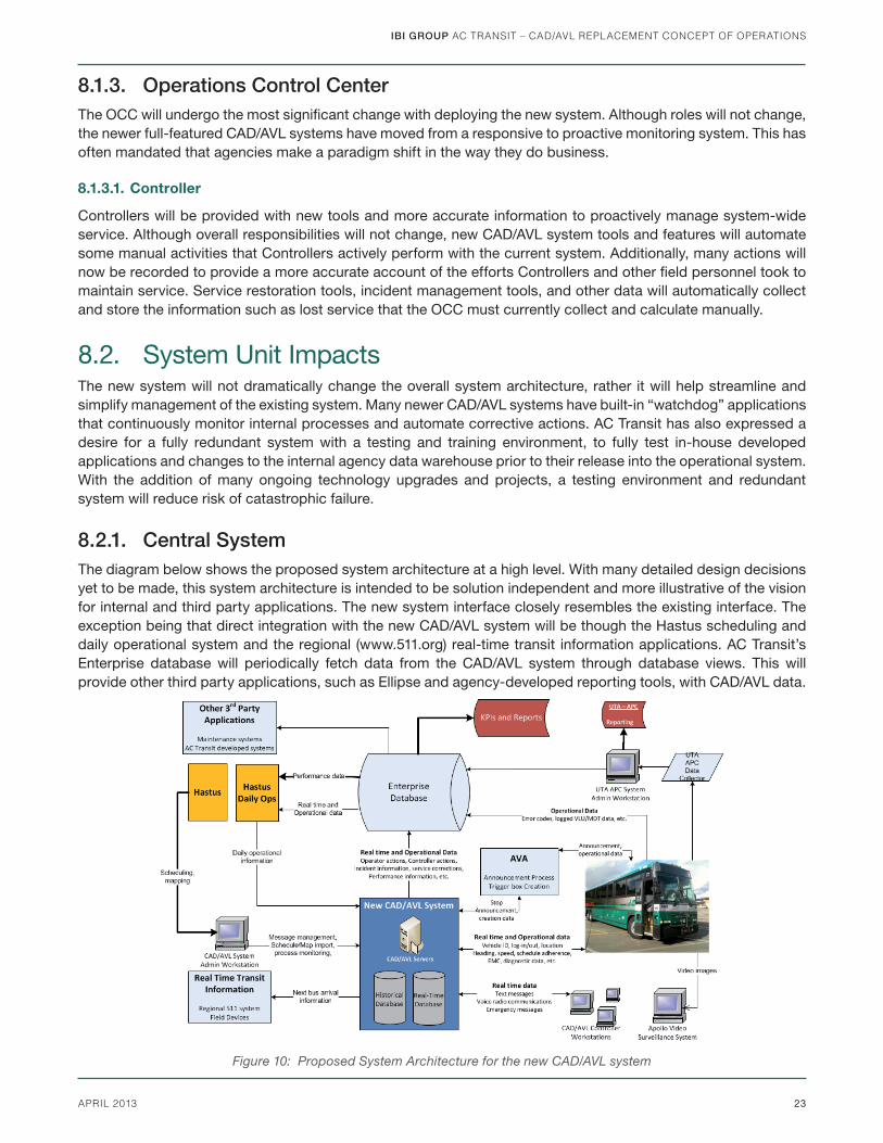
8.2.1. Central SystemThe diagram below shows the proposed system architecture at a high level. With many detailed design decisions yet to be made, this system architecture is intended to be solution independent and more illustrative of the vision for internal and third party applications. The new system interface closely resembles the existing interface. The exception being that direct integration with the new CAD/AVL system will be though the Hastus scheduling and daily operational system and the regional (www.511.org) real-time transit information applications. AC Transit’s Enterprise database will periodically fetch data from the CAD/AVL system through database views. This will provide other third party applications, such as Ellipse and agency-developed reporting tools, with CAD/AVL data.
Figure 10: Proposed System Architecture for the new CAD/AVL system

IBI GROUP AC TRANSIT – CAD/AVL REPLACEMENT CONCEPT OF OPERATIONS
24 APRIL 2013
8.2.2. CommunicationsThe replacement CAD/AVL system will require more frequent and reliable vehicle location updates, better integration with existing systems, and more robust dispatching features and functions. The current communications system is unable to support this and future initiatives for the agency. In a parallel effort, a detailed analysis of the existing voice and data radio communications options available to the agency is available in the technical memorandum Communication System Alternatives. For the purpose of this operational concept, it will be assumed that the voice and data radio communications system solution for the replacement CAD/AVL system will be able to support agency needs. The future radio system will have the capability to support a minimum of seven voice radio consoles for each existing controller workstation and if possible, expand to include potential new controller workstations. For example, this may include adding an additional console in the Superintendent’s offi ce.
8.2.3. Customer Information SystemsAC Transit prefers the replacement system to provide transit information directly to the region’s 511 system, eliminating NextBus as the go-between. The new system’s features and functions will provide customer service applications with more accurate information when service measures are taken. This will increase the accuracy of information disseminated to the traveling public. With integration of the agency’s AVA system, Operators will have more control over the audio volume and the ability to repeat or replay announcements. The OCC will also have the ability to disable a malfunctioning onboard AVA system remotely. The agency would also like to expand the AVA system to include messages that are tied to specifi c locations, bus stops or other events not currently available (i.e. wheel chair ramp deploying).
8.2.4. Service PlanningService planning and scheduling processes will generally remain unchanged. Field information and data will still be available. However, rather than pulling this information directly from the CAD/AVL system, AC Transit is considering using the Enterprise Database. More comprehensive information from the onboard systems will also be available to the scheduling department to improve schedules and generate more accurate and comprehensive reports.
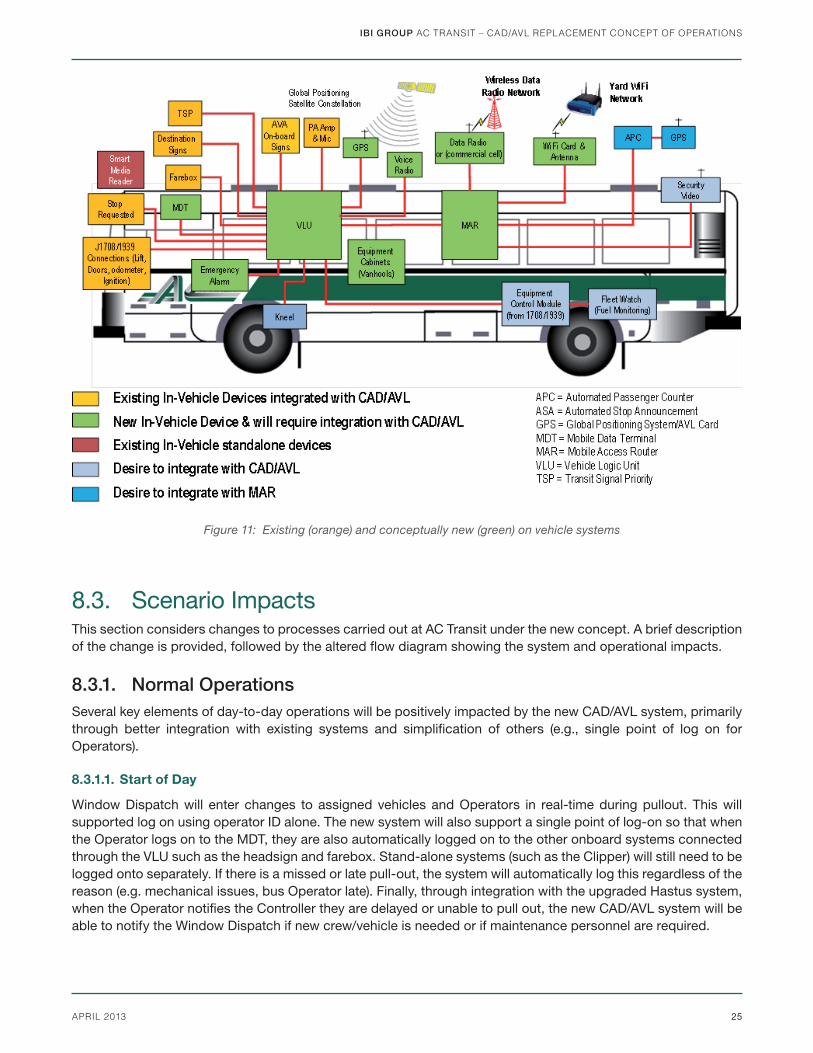
8.2.5. OnBoard Vehicle Systems Integration with other onboard equipment through the VLU will provide the agency with increased effi ciencies allowing a single point of log-on for all integrated devices. The smart media reader (Clipper equipment) is a proprietary device that will not be able to integrate with the replacement system and is represented as a standalone system. The diagram below provides a high-level overview of the future onboard architecture.
As CAD/AVL systems become more modular, transit agencies are realizing the benefi t of incorporating an onboard network similar to an offi ce IT environment to help future-proof buses. AC Transit’s future onboard system will include a mobile access router (MAR) to provide the agency with multi-path communications between the onboard equipment and central system and the ability to integrate with new and existing devices. The diagram above illustrates an example future replacement system using a MAR. The MAR will integrate with the vendor provided VLU, and the existing APC and Apollo security surveillance system. If the agency chooses cellular data communications as part of the replacement project, or as a future consideration, the MAR provides fl exibility to change carriers or upgrade modem cards with minimal costs to the agency.
IBI GROUP AC TRANSIT – CAD/AVL REPLACEMENT CONCEPT OF OPERATIONS
25APRIL 2013
8.3. Scenario ImpactsThis section considers changes to processes carried out at AC Transit under the new concept. A brief description of the change is provided, followed by the altered fl ow diagram showing the system and operational impacts.
8.3.1. Normal OperationsSeveral key elements of day-to-day operations will be positively impacted by the new CAD/AVL system, primarily through better integration with existing systems and simplifi cation of others (e.g., single point of log on for Operators).
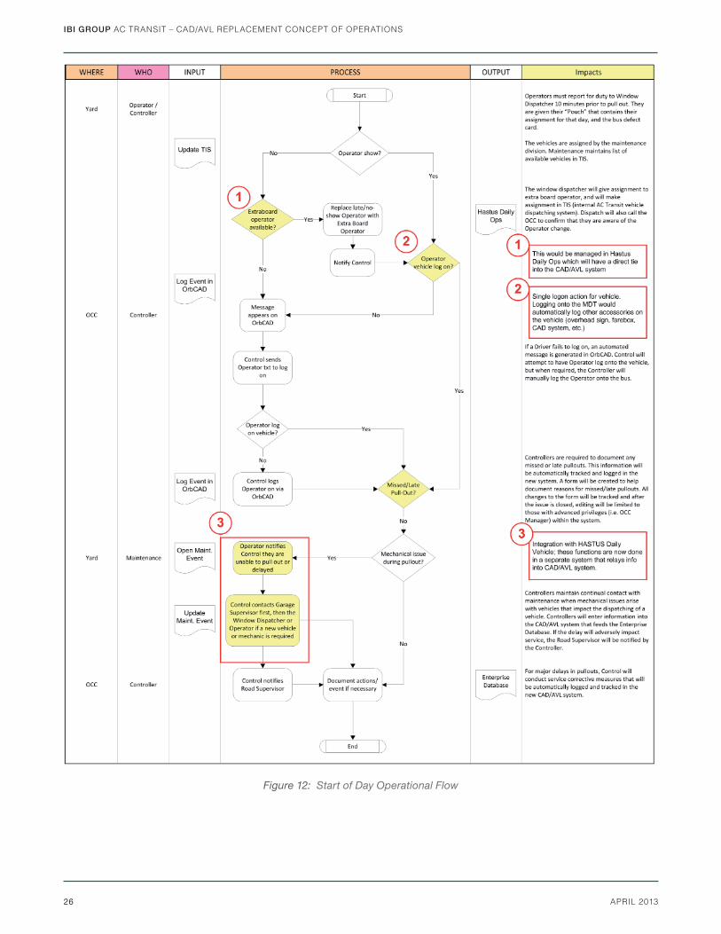
8.3.1.1. Start of Day
Window Dispatch will enter changes to assigned vehicles and Operators in real-time during pullout. This will supported log on using operator ID alone. The new system will also support a single point of log-on so that when the Operator logs on to the MDT, they are also automatically logged on to the other onboard systems connected through the VLU such as the headsign and farebox. Stand-alone systems (such as the Clipper) will still need to be logged onto separately. If there is a missed or late pull-out, the system will automatically log this regardless of the reason (e.g. mechanical issues, bus Operator late). Finally, through integration with the upgraded Hastus system, when the Operator notifi es the Controller they are delayed or unable to pull out, the new CAD/AVL system will be able to notify the Window Dispatch if new crew/vehicle is needed or if maintenance personnel are required.
Figure 11: Existing (orange) and conceptually new (green) on vehicle systems
IBI GROUP AC TRANSIT – CAD/AVL REPLACEMENT CONCEPT OF OPERATIONS
26 APRIL 2013
Figure 12: Start of Day Operational Flow
IBI GROUP AC TRANSIT – CAD/AVL REPLACEMENT CONCEPT OF OPERATIONS
27APRIL 2013
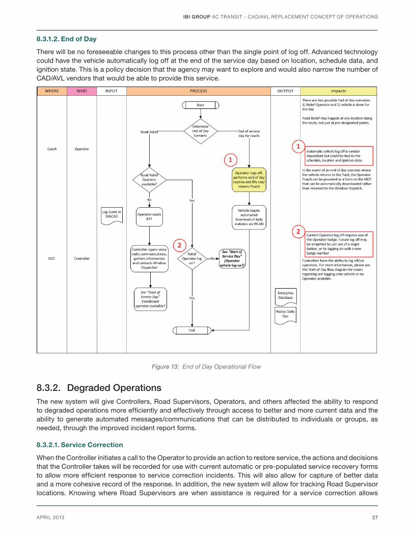
8.3.1.2. End of Day
There will be no foreseeable changes to this process other than the single point of log off. Advanced technology could have the vehicle automatically log off at the end of the service day based on location, schedule data, and ignition state. This is a policy decision that the agency may want to explore and would also narrow the number of CAD/AVL vendors that would be able to provide this service.
8.3.2. Degraded OperationsThe new system will give Controllers, Road Supervisors, Operators, and others affected the ability to respond to degraded operations more effi ciently and effectively through access to better and more current data and the ability to generate automated messages/communications that can be distributed to individuals or groups, as needed, through the improved incident report forms.
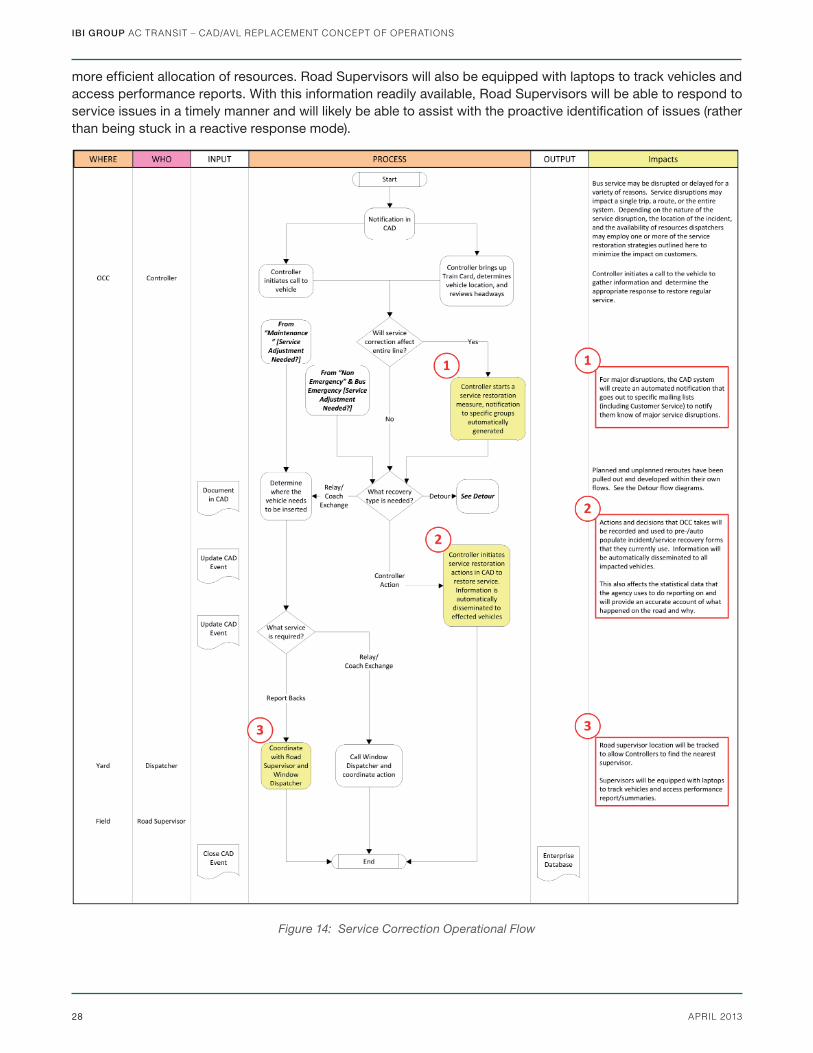
8.3.2.1. Service Correction
When the Controller initiates a call to the Operator to provide an action to restore service, the actions and decisions that the Controller takes will be recorded for use with current automatic or pre-populated service recovery forms to allow more effi cient response to service correction incidents. This will also allow for capture of better data and a more cohesive record of the response. In addition, the new system will allow for tracking Road Supervisor locations. Knowing where Road Supervisors are when assistance is required for a service correction allows
Figure 13: End of Day Operational Flow
IBI GROUP AC TRANSIT – CAD/AVL REPLACEMENT CONCEPT OF OPERATIONS
28 APRIL 2013
more effi cient allocation of resources. Road Supervisors will also be equipped with laptops to track vehicles and access performance reports. With this information readily available, Road Supervisors will be able to respond to service issues in a timely manner and will likely be able to assist with the proactive identifi cation of issues (rather than being stuck in a reactive response mode).
Figure 14: Service Correction Operational Flow
IBI GROUP AC TRANSIT – CAD/AVL REPLACEMENT CONCEPT OF OPERATIONS
29APRIL 2013
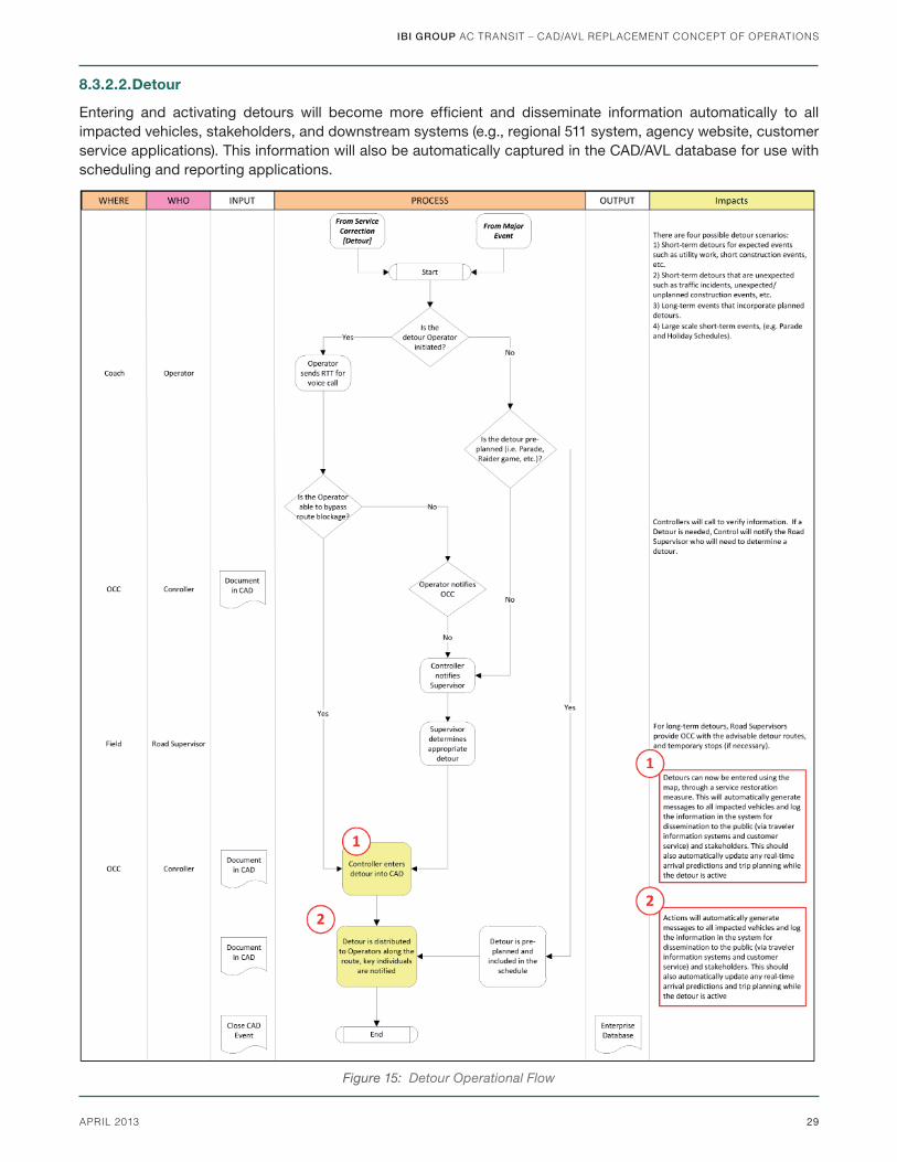
8.3.2.2. Detour
Entering and activating detours will become more effi cient and disseminate information automatically to all impacted vehicles, stakeholders, and downstream systems (e.g., regional 511 system, agency website, customer service applications). This information will also be automatically captured in the CAD/AVL database for use with scheduling and reporting applications.
Figure 15: Detour Operational Flow

IBI GROUP AC TRANSIT – CAD/AVL REPLACEMENT CONCEPT OF OPERATIONS
30 APRIL 2013
8.3.2.3. Non-Emergency Degraded Service Correction
The greatest impact to operations for this scenario will come from the ability of Controllers to make better decisions about Road Supervisor resourcing through knowing their map location, and whether they are currently busy (e.g., another Controller has requested their assistance). Also, with the laptops, Road Supervisors will have tools/applications to complete work tickets/incident forms immediately in the fi eld.
8.3.2.4. Bus Bridge
The beginning of this process will be improved by the new CAD/AVL system. The future system will know when vehicles have been taken off route and whether the vehicle is removed from service. This information will also be provided to downstream applications to allow for clearer data and better reporting on these situations. Vehicles taken out of service will be removed from reporting on all customer information applications (e.g., real-time information signs as bus stops) and replaced with information about the vehicle now placed into service. In addition, communication to Operators will be improved with the ability to route a single text message/canned instruction to a group of Operators, vehicles, blocks, or routes. Finally, when the bus bridge action is complete, all necessary individuals who need to know will be updated automatically based on the information entered into the service recovery form/incident management form.
Figure 16: Non Emergency Operational Flow

IBI GROUP AC TRANSIT – CAD/AVL REPLACEMENT CONCEPT OF OPERATIONS
31APRIL 2013
Figure 17: Bus Bridge Operational Flow
8.3.3. Emergency OperationsPrimary impacts to emergency operations will be in the access Controllers will have to onboard emergency alarm equipment and the ability to override or downgrade current alarms. In addition, increased automation of notifi cations will allow for more effi cient use of resources through timely notifi cation of situational changes.
8.3.3.1. Bus Emergency
The greatest benefi t to emergency operations in the new CAD/AVL system will be the ability of Controllers to access or reset a current alarm rather than being required to send a Road Supervisor to the vehicle to reset the radio. This will be a signifi cant operational improvement allowing for much better control and use of resources.

IBI GROUP AC TRANSIT – CAD/AVL REPLACEMENT CONCEPT OF OPERATIONS
32 APRIL 2013
Additionally, Road Supervisors will have GPS enabled radios allowing their location to be sent to the OCC. This will allow Controllers the ability to quickly locate the nearest Road Supervisor to respond to bus emergencies.
Figure 18: Bus Emergency Operational Flow
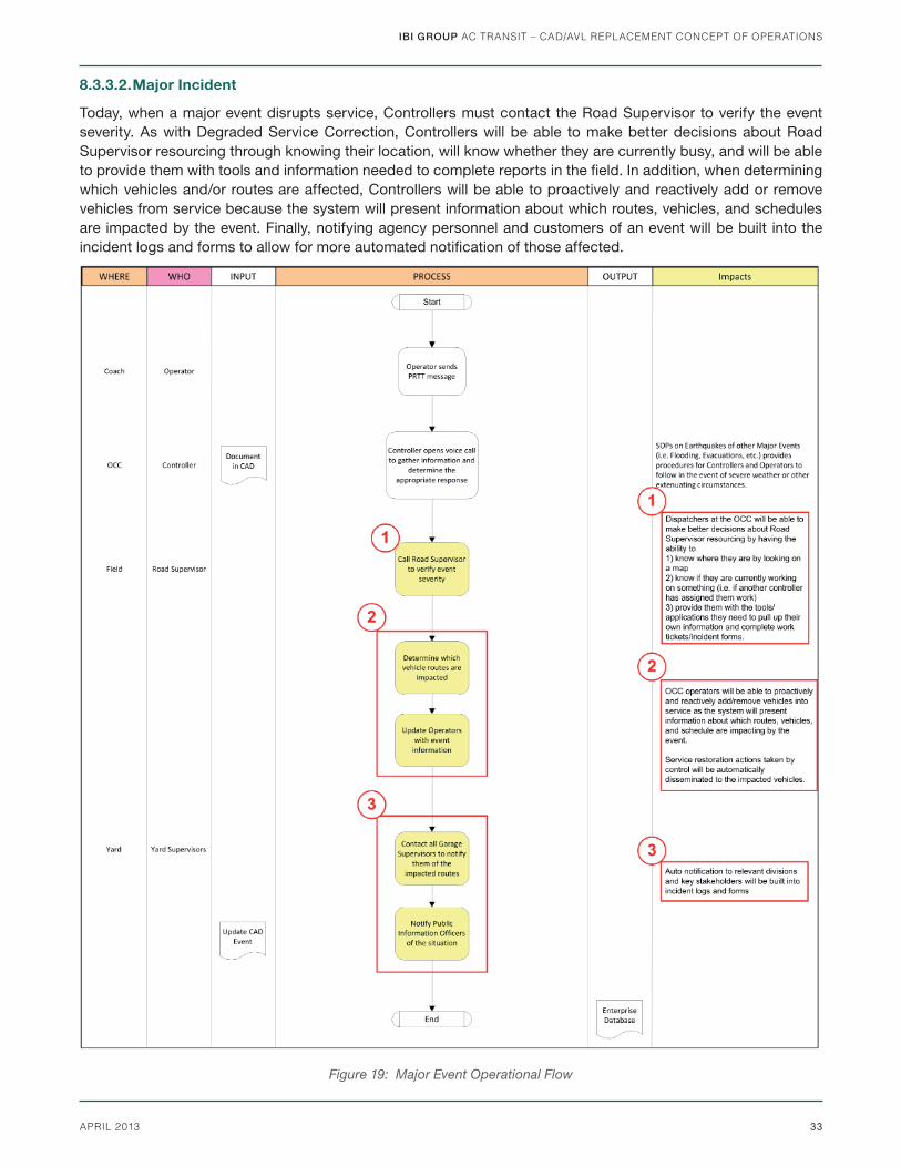
IBI GROUP AC TRANSIT – CAD/AVL REPLACEMENT CONCEPT OF OPERATIONS
33APRIL 2013
8.3.3.2. Major Incident
Today, when a major event disrupts service, Controllers must contact the Road Supervisor to verify the event severity. As with Degraded Service Correction, Controllers will be able to make better decisions about Road Supervisor resourcing through knowing their location, will know whether they are currently busy, and will be able to provide them with tools and information needed to complete reports in the fi eld. In addition, when determining which vehicles and/or routes are affected, Controllers will be able to proactively and reactively add or remove vehicles from service because the system will present information about which routes, vehicles, and schedules are impacted by the event. Finally, notifying agency personnel and customers of an event will be built into the incident logs and forms to allow for more automated notifi cation of those affected.
Figure 19: Major Event Operational Flow
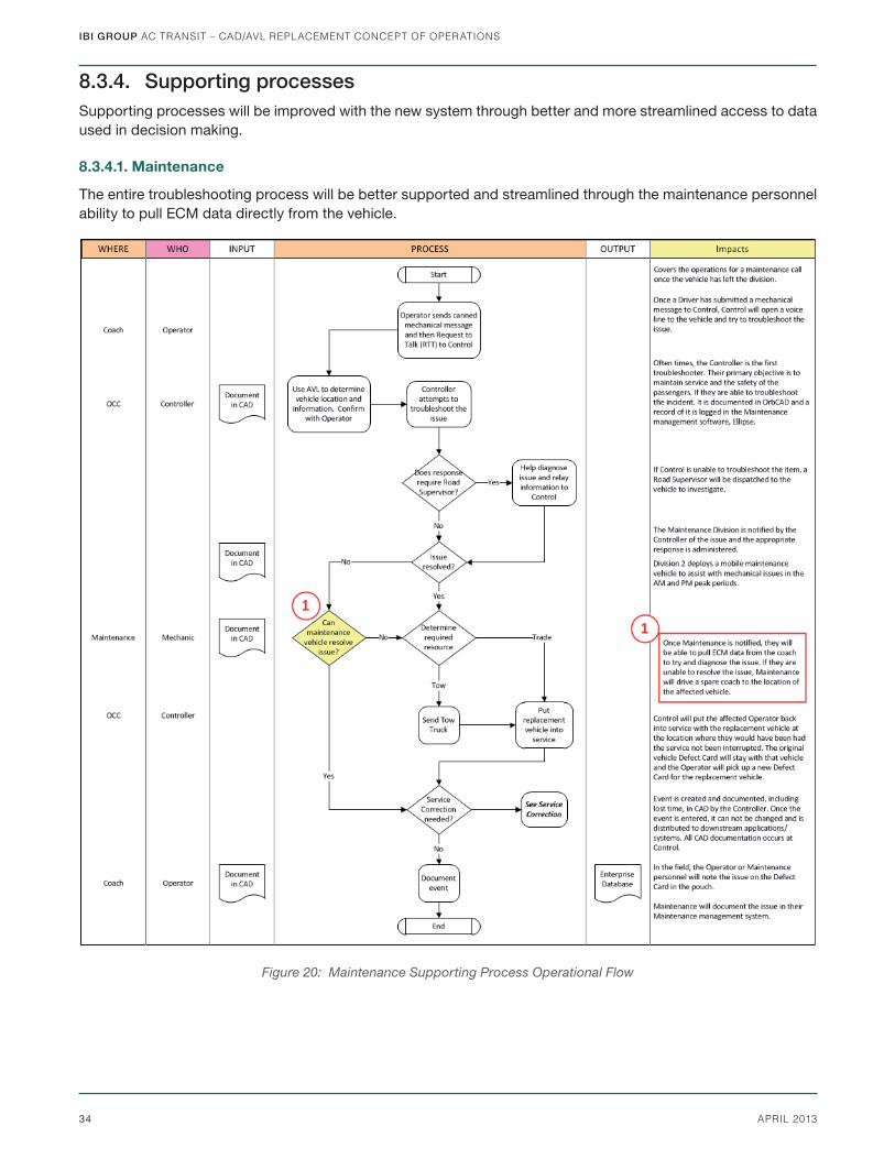
IBI GROUP AC TRANSIT – CAD/AVL REPLACEMENT CONCEPT OF OPERATIONS
34 APRIL 2013
8.3.4. Supporting processesSupporting processes will be improved with the new system through better and more streamlined access to data used in decision making.
8.3.4.1. Maintenance
The entire troubleshooting process will be better supported and streamlined through the maintenance personnel ability to pull ECM data directly from the vehicle.
Figure 20: Maintenance Supporting Process Operational Flow
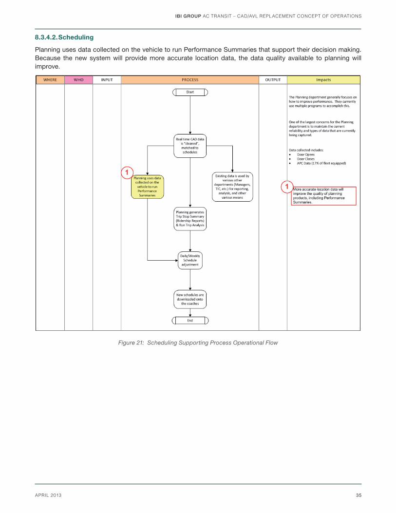
IBI GROUP AC TRANSIT – CAD/AVL REPLACEMENT CONCEPT OF OPERATIONS
35APRIL 2013
8.3.4.2. Scheduling
Planning uses data collected on the vehicle to run Performance Summaries that support their decision making. Because the new system will provide more accurate location data, the data quality available to planning will improve.
9. Appendices
Figure 21: Scheduling Supporting Process Operational Flow

APPENDIX A
EXISTING OPERATIONAL FLOW DIAGRAMS

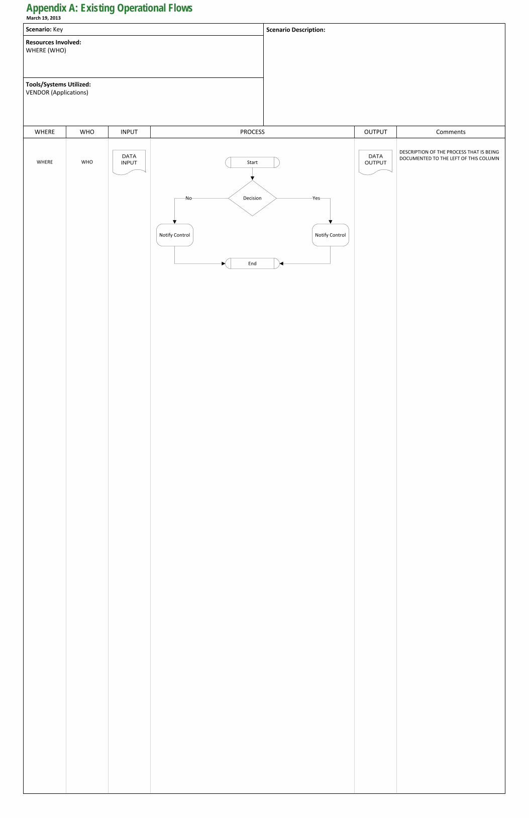
PROCESS OUTPUT CommentsWHERE INPUT
Scenario Description:
WHO
Resources Involved:WHERE (WHO)
Tools/Systems Utilized:VENDOR (Applications)
DESCRIPTION OF THE PROCESS THAT IS BEING DOCUMENTED TO THE LEFT OF THIS COLUMN
Start
YesDecisionNo
Notify Control
DATA INPUTWHERE WHO
Scenario: Key
DATA OUTPUT
Notify Control
End
Appendix A: Existing Operational FlowsMarch 19, 2013
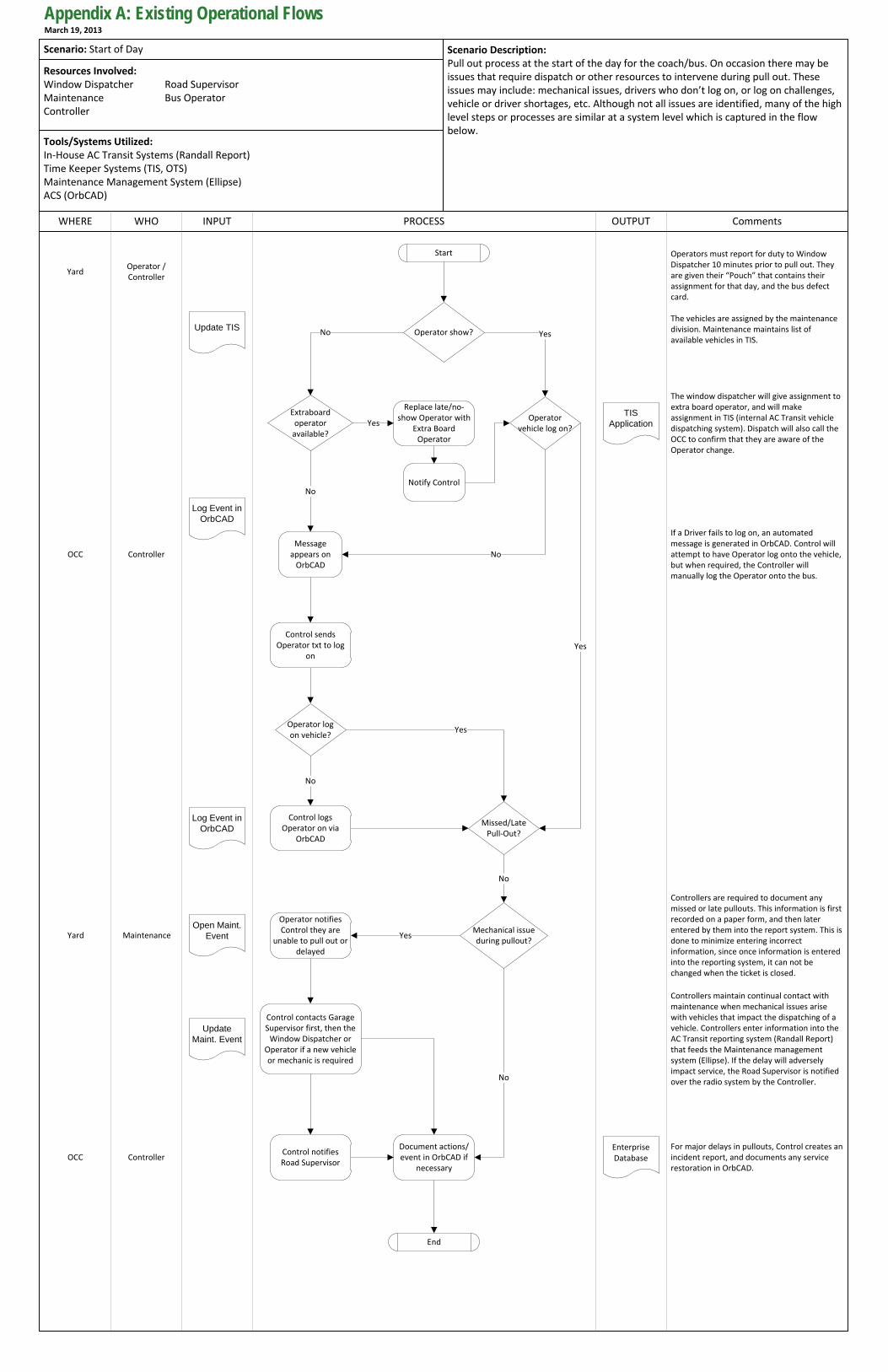
PROCESS OUTPUT CommentsWHERE INPUT
Scenario Description:Pull out process at the start of the day for the coach/bus. On occasion there may be issues that require dispatch or other resources to intervene during pull out. These issues may include: mechanical issues, drivers who don’t log on, or log on challenges, vehicle or driver shortages, etc. Although not all issues are identified, many of the high level steps or processes are similar at a system level which is captured in the flow below.
WHO
Resources Involved:Window Dispatcher Road SupervisorMaintenance Bus OperatorController
Tools/Systems Utilized:In-House AC Transit Systems (Randall Report)Time Keeper Systems (TIS, OTS)Maintenance Management System (Ellipse)ACS (OrbCAD)
Missed/Late Pull-Out?
Mechanical issue during pullout?
Controllers are required to document any missed or late pullouts. This information is first recorded on a paper form, and then later entered by them into the report system. This is done to minimize entering incorrect information, since once information is entered into the reporting system, it can not be changed when the ticket is closed.
If a Driver fails to log on, an automated message is generated in OrbCAD. Control will attempt to have Operator log onto the vehicle, but when required, the Controller will manually log the Operator onto the bus.
Controllers maintain continual contact with maintenance when mechanical issues arise with vehicles that impact the dispatching of a vehicle. Controllers enter information into the AC Transit reporting system (Randall Report) that feeds the Maintenance management system (Ellipse). If the delay will adversely impact service, the Road Supervisor is notified over the radio system by the Controller.No
No
Yes
Control contacts Garage Supervisor first, then the
Window Dispatcher or Operator if a new vehicle or mechanic is required
End
For major delays in pullouts, Control creates an incident report, and documents any service restoration in OrbCAD.
Operator log on vehicle?
Yes
No
Extraboard operator
available?Yes
No
The window dispatcher will give assignment to extra board operator, and will make assignment in TIS (internal AC Transit vehicle dispatching system). Dispatch will also call the OCC to confirm that they are aware of the Operator change.
Start
Operator vehicle log on?
No
Yes
YesOperator show?No
Operators must report for duty to Window Dispatcher 10 minutes prior to pull out. They are given their “Pouch” that contains their assignment for that day, and the bus defect card.
The vehicles are assigned by the maintenance division. Maintenance maintains list of available vehicles in TIS.
Replace late/no-show Operator with
Extra Board Operator
Control sends Operator txt to log
on
Notify Control
Message appears on
OrbCAD
Control logs Operator on via
OrbCAD
Operator notifies Control they are
unable to pull out or delayed
Control notifies Road Supervisor
Document actions/event in OrbCAD if
necessary
Update TIS
YardOperator / Controller
Log Event in OrbCAD
Open Maint. Event
Update Maint. Event
Enterprise Database
OCC Controller
Yard Maintenance
OCC Controller
Scenario: Start of Day
TIS Application
Log Event in OrbCAD
Appendix A: Existing Operational FlowsMarch 19, 2013
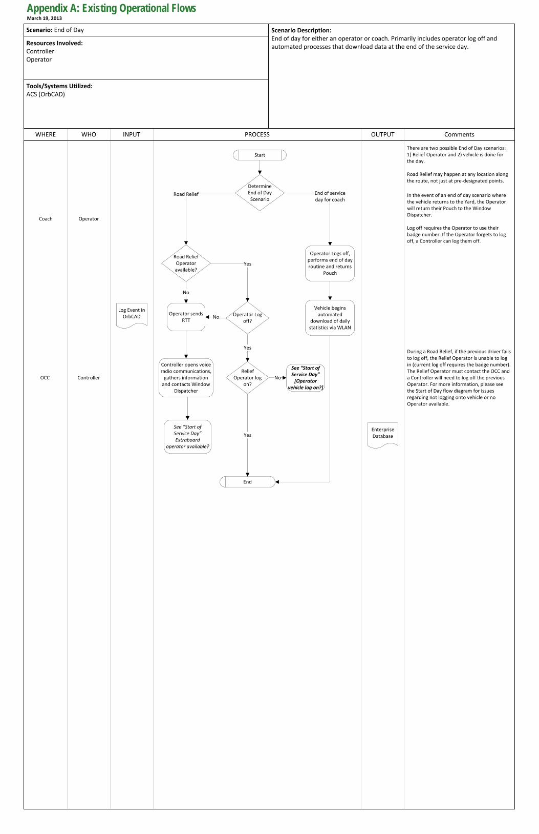
PROCESS OUTPUT CommentsWHERE INPUT
Scenario Description:End of day for either an operator or coach. Primarily includes operator log off and automated processes that download data at the end of the service day.
WHO
Resources Involved:ControllerOperator
Tools/Systems Utilized:ACS (OrbCAD)
Scenario: End of Day
Road Relief End of service day for coach
Determine End of Day Scenario
During a Road Relief, if the previous driver fails to log off, the Relief Operator is unable to log in (current log off requires the badge number). The Relief Operator must contact the OCC and a Controller will need to log off the previous Operator. For more information, please see the Start of Day flow diagram for issues regarding not logging onto vehicle or no Operator available.
There are two possible End of Day scenarios:1) Relief Operator and 2) vehicle is done for the day.
Road Relief may happen at any location along the route, not just at pre-designated points.
Road Relief Operator available?
Yes
Relief Operator log
on?
End
Yes
Start
In the event of an end of day scenario where the vehicle returns to the Yard, the Operator will return their Pouch to the Window Dispatcher.
No
See “Start of Service Day”
[Operator vehicle log on?]
No
Operator sends RTT
Controller opens voice radio communications,
gathers information and contacts Window
Dispatcher
See “Start of Service Day” Extraboard
operator available?
Log off requires the Operator to use their badge number. If the Operator forgets to log off, a Controller can log them off.
Log Event in OrbCAD
Enterprise Database
Operator Logs off, performs end of day routine and returns
Pouch
Operator Log off?
Yes
No
Vehicle begins automated
download of daily statistics via WLAN
OperatorCoach
OCC Controller
Appendix A: Existing Operational FlowsMarch 19, 2013
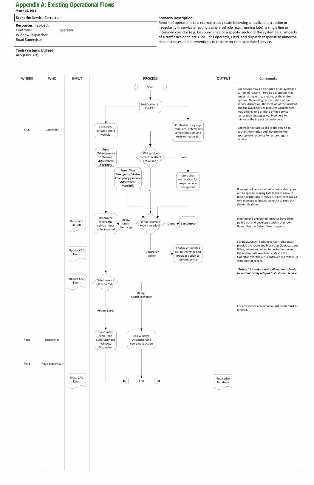
PROCESS OUTPUT CommentsWHERE INPUT
Scenario Description:Return of operations to a normal steady state following a localized disruption or irregularity in service affecting a single vehicle (e.g., running late), a single line or interlined corridor (e.g. bus bunching), or a specific sector of the system (e.g., impacts of a traffic accident, etc.). Includes operator, Field, and dispatch response to abnormal circumstances and interventions to restore on-time scheduled service.
WHO
Resources Involved:Controller OperatorWindow DispatcherRoad Supervisor
Tools/Systems Utilized:ACS (OrbCAD)
Scenario: Service Correction
StartBus service may be disrupted or delayed for a variety of reasons. Service disruptions may impact a single trip, a route, or the entire system. Depending on the nature of the service disruption, the location of the incident, and the availability of resources dispatchers may employ one or more of the service restoration strategies outlined here to minimize the impact on customers.
What recovery type is needed?
Controller initiates a call to the vehicle to gather information and determine the appropriate response to restore regular service.
OCC
Relay/Coach
Exchange
What service is required?
Relay/Coach Exchange
Report Backs
End
For Relay/Coach Exchange: Controller must provide the route and block that Operators are filling, where and when to begin the run and the appropriate overhead codes to the Operator over the air. Controller will follow-up with text for record.
Controller Action
For any service correction a CAD event must be created.
Will service correction affect
entire line?
No
Yes
If an entire line is affected, a notification goes out to specific mailing lists to them know of major disruptions to service. Controller uses a text message to busses en-route to send out the notifications.
Enterprise Database
Detour
Planned and unplanned reroutes have been pulled out and developed within their own flows. See the Detour flow diagrams.
Document in CAD
Update CAD Event
Update CAD Event
Close CAD Event
*Future* All major service disruptions should be automatically relayed to Customer Service
Controller
Notification in OrbCAD
Controller initiates call to
vehicle
Controller brings up Train Card, determines
vehicle location, and reviews headways
Controller notification for major service disruptions
Controller initiates call to Operator and provides action to
restore service
Determine where the
vehicle needs to be inserted
Call Window Dispatcher and
coordinate action
Coordinate with Road
Supervisor and Window
Dispatcher
From “Maintenance
” [Service Adjustment Needed?]
From “Non Emergency” & Bus Emergency [Service
Adjustment Needed?]
See Detour
Yard Dispatcher
Field Road Supervisor
Appendix A: Existing Operational FlowsMarch 19, 2013
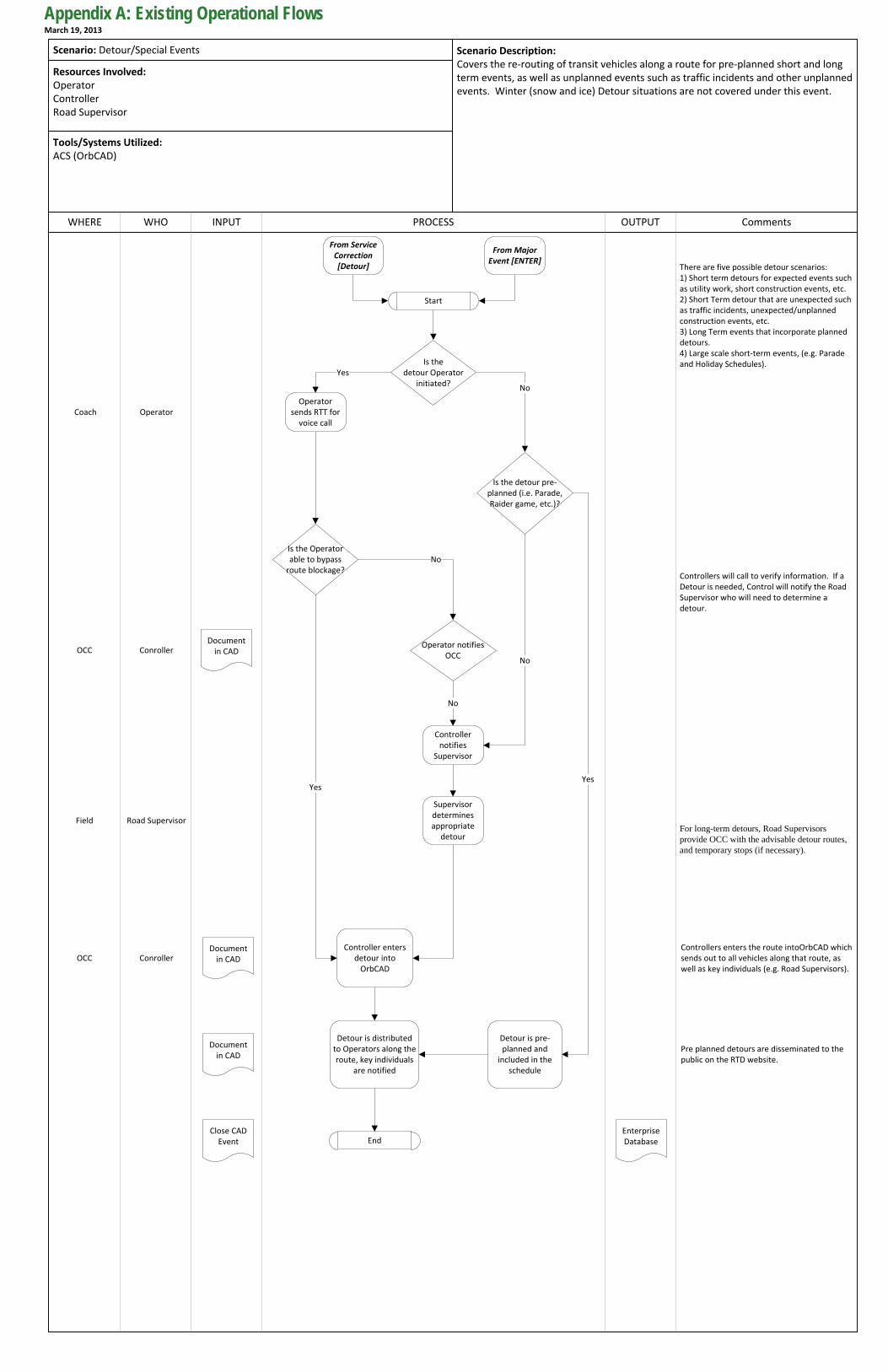
PROCESS OUTPUT CommentsWHERE INPUT
Scenario Description:Covers the re-routing of transit vehicles along a route for pre-planned short and long term events, as well as unplanned events such as traffic incidents and other unplanned events. Winter (snow and ice) Detour situations are not covered under this event.
WHO
Resources Involved:OperatorControllerRoad Supervisor
Tools/Systems Utilized:ACS (OrbCAD)
Scenario: Detour/Special Events
Yes
Is the detour pre-planned (i.e. Parade, Raider game, etc.)?
There are five possible detour scenarios: 1) Short term detours for expected events such as utility work, short construction events, etc.2) Short Term detour that are unexpected such as traffic incidents, unexpected/unplanned construction events, etc.3) Long Term events that incorporate planned detours.4) Large scale short-term events, (e.g. Parade and Holiday Schedules).
End
Start
Coach
For long-term detours, Road Supervisors provide OCC with the advisable detour routes, and temporary stops (if necessary).
Is the Operator able to bypass
route blockage?
Yes
Controllers will call to verify information. If a Detour is needed, Control will notify the Road Supervisor who will need to determine a detour.
Controllers enters the route intoOrbCAD which sends out to all vehicles along that route, as well as key individuals (e.g. Road Supervisors).
Document in CAD
Enterprise Database
Is the detour Operator
initiated?No
Pre planned detours are disseminated to the public on the RTD website.
No
Operator notifies OCC
No
No
Operator sends RTT for
voice call
Controller notifies
Supervisor
Supervisor determines appropriate
detour
Controller enters detour into
OrbCAD
Detour is distributed to Operators along the route, key individuals
are notified
Detour is pre-planned and
included in the schedule
Operator
OCC Conroller
From Service Correction [Detour]
From Major Event [ENTER]
Yes
Field Road Supervisor
OCC ConrollerDocument
in CAD
Document in CAD
Close CAD Event
Appendix A: Existing Operational FlowsMarch 19, 2013
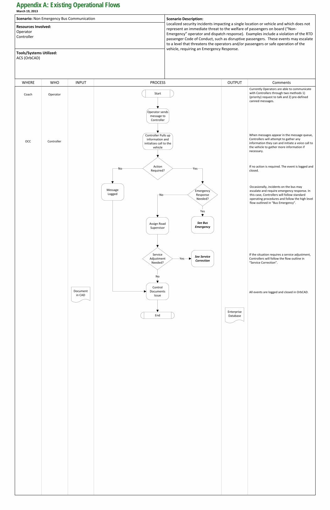
PROCESS OUTPUT CommentsWHERE INPUT
Scenario Description:Localized security incidents impacting a single location or vehicle and which does not represent an immediate threat to the welfare of passengers on board (“Non-Emergency” operator and dispatch response). Examples include a violation of the RTD passenger Code of Conduct, such as disruptive passengers. These events may escalate to a level that threatens the operators and/or passengers or safe operation of the vehicle, requiring an Emergency Response.
WHO
Resources Involved:OperatorController
Tools/Systems Utilized:ACS (OrbCAD)
Scenario: Non Emergency Bus Communication
Start
Action Required?
Operator sends message to Controller
Controller Pulls up information and
initializes call to the vehicle
End
Emergency Response Needed?
Message Logged
Assign Road Supervisor
See Bus Emergency
No Yes
No
Yes
Service Adjustment
Needed?
Control Documents
Issue
See Service Correction
Yes
No
Coach Operator
OCC Controller
Document in CAD
Enterprise Database
Currently Operators are able to communicate with Controllers through two methods 1) (priority) request to talk and 2) pre-defined canned messages.
When messages appear in the message queue, Controllers will attempt to gather any information they can and initiate a voice call to the vehicle to gather more information if necessary.
Occasionally, incidents on the bus may escalate and require emergency response. In this case, Controllers will follow standard operating procedures and follow the high level flow outlined in “Bus Emergency”.
If no action is required. The event is logged and closed.
If the situation requires a service adjustment, Controllers will follow the flow outline in “Service Correction”.
All events are logged and closed in OrbCAD.
Appendix A: Existing Operational FlowsMarch 19, 2013
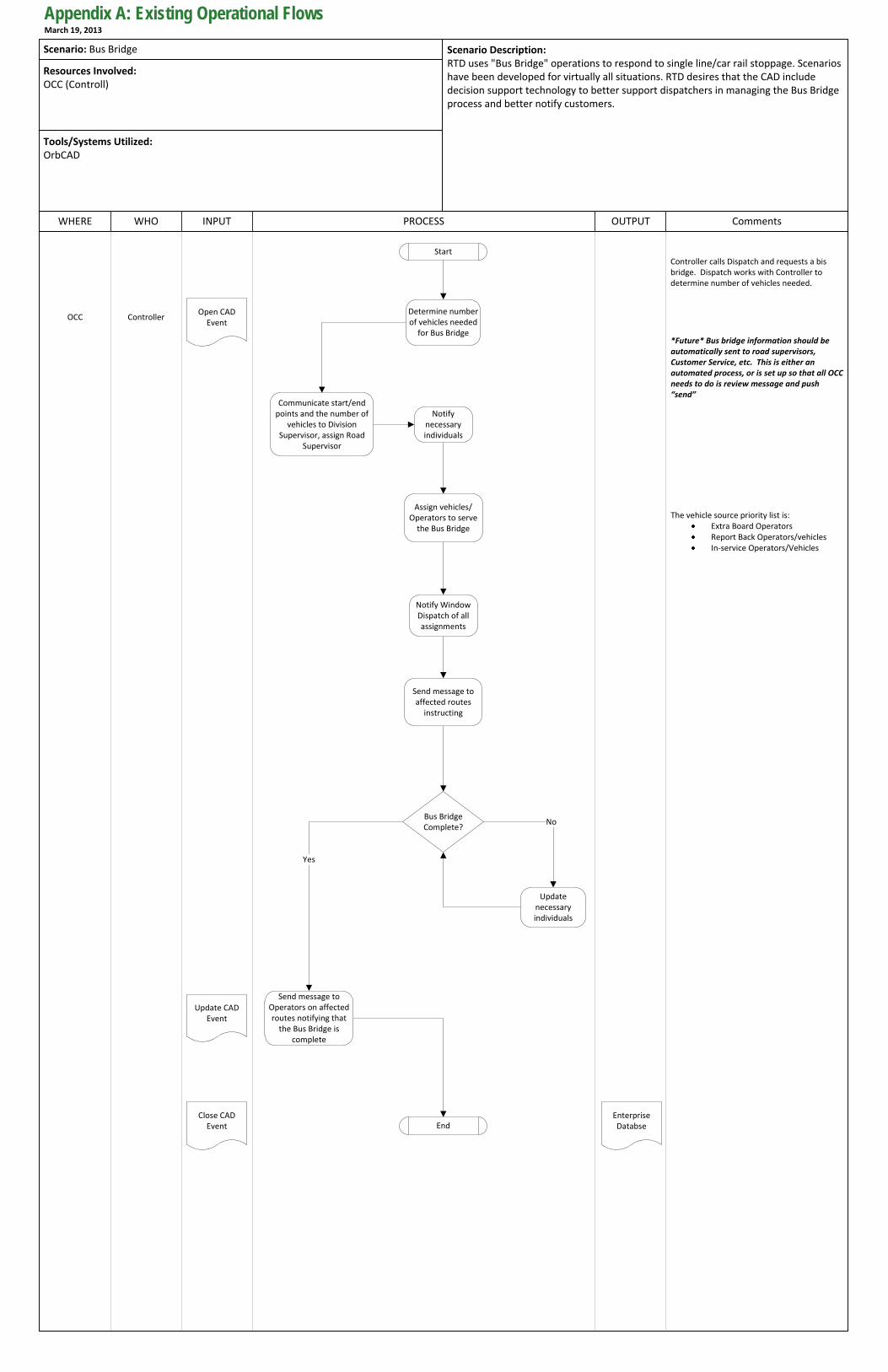
PROCESS OUTPUT CommentsWHERE INPUT
Scenario Description:RTD uses "Bus Bridge" operations to respond to single line/car rail stoppage. Scenarios have been developed for virtually all situations. RTD desires that the CAD include decision support technology to better support dispatchers in managing the Bus Bridge process and better notify customers.
WHO
Resources Involved:OCC (Controll)
Tools/Systems Utilized:OrbCAD
Determine number of vehicles needed
for Bus Bridge
OCC Controller
Scenario: Bus Bridge
Start
The vehicle source priority list is:Extra Board OperatorsReport Back Operators/vehiclesIn-service Operators/Vehicles
End
Open CAD Event
Controller calls Dispatch and requests a bis bridge. Dispatch works with Controller to determine number of vehicles needed.
Bus Bridge Complete?
Yes
No
*Future* Bus bridge information should be automatically sent to road supervisors, Customer Service, etc. This is either an automated process, or is set up so that all OCC needs to do is review message and push “send”
Communicate start/end points and the number of
vehicles to Division Supervisor, assign Road
Supervisor
Notify necessary individuals
Assign vehicles/Operators to serve
the Bus Bridge
Notify Window Dispatch of all assignments
Send message to affected routes
instructing
Send message to Operators on affected routes notifying that
the Bus Bridge is complete
Update CAD Event
Close CAD Event
Enterprise Databse
Update necessary individuals
Appendix A: Existing Operational FlowsMarch 19, 2013
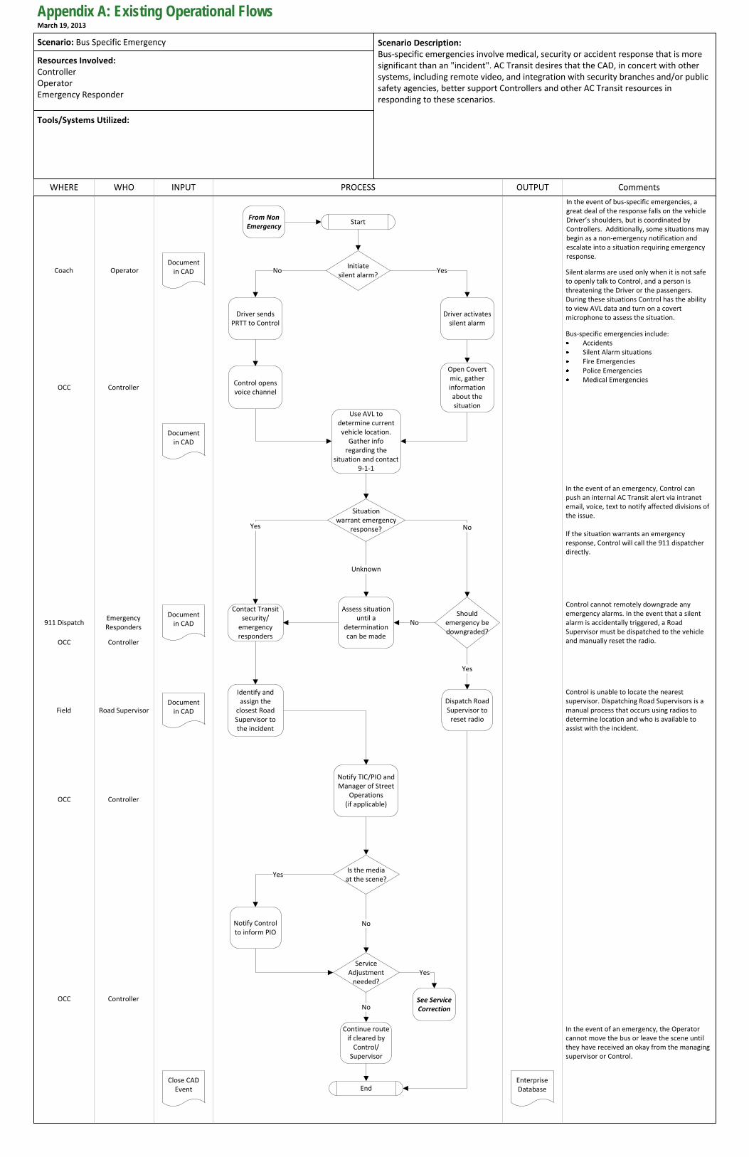
PROCESS OUTPUT CommentsWHERE INPUT
Scenario Description:Bus-specific emergencies involve medical, security or accident response that is more significant than an "incident". AC Transit desires that the CAD, in concert with other systems, including remote video, and integration with security branches and/or public safety agencies, better support Controllers and other AC Transit resources in responding to these scenarios.
WHO
Resources Involved:ControllerOperatorEmergency Responder
Tools/Systems Utilized:
Scenario: Bus Specific Emergency
Start
Is the mediaat the scene?
In the event of an emergency, the Operator cannot move the bus or leave the scene until they have received an okay from the managing supervisor or Control.
In the event of bus-specific emergencies, a great deal of the response falls on the vehicle Driver’s shoulders, but is coordinated by Controllers. Additionally, some situations may begin as a non-emergency notification and escalate into a situation requiring emergency response.
Initiate silent alarm?
No Silent alarms are used only when it is not safe to openly talk to Control, and a person is threatening the Driver or the passengers. During these situations Control has the ability to view AVL data and turn on a covert microphone to assess the situation.
Yes
Bus-specific emergencies include:AccidentsSilent Alarm situationsFire EmergenciesPolice EmergenciesMedical Emergencies
Yes
End
No
Situation warrant emergency
response?Yes
Unknown
Should emergency be downgraded?
No
Yes
No
Control cannot remotely downgrade any emergency alarms. In the event that a silent alarm is accidentally triggered, a Road Supervisor must be dispatched to the vehicle and manually reset the radio.
In the event of an emergency, Control can push an internal AC Transit alert via intranet email, voice, text to notify affected divisions of the issue.
If the situation warrants an emergency response, Control will call the 911 dispatcher directly.
Driver sends PRTT to Control
Control opens voice channel
Driver activates silent alarm
Open Covert mic, gather information about the situation
Use AVL to determine current vehicle location.
Gather info regarding the
situation and contact 9-1-1
Contact Transit security/
emergency responders
Identify and assign the
closest Road Supervisor to the incident
Notify TIC/PIO and Manager of Street
Operations (if applicable)
Notify Control to inform PIO
Continue route if cleared by
Control/Supervisor
Dispatch Road Supervisor to
reset radio
Assess situation until a
determination can be made
Control is unable to locate the nearest supervisor. Dispatching Road Supervisors is a manual process that occurs using radios to determine location and who is available to assist with the incident.
Document in CAD
Document in CAD
Document in CAD
Close CAD Event
Document in CAD
Enterprise Database
Coach Operator
OCC Controller
Field Road Supervisor
OCC Controller
OCC Controller
Service Adjustment
needed?
No
Yes
See Service Correction
911 DispatchEmergency Responders
OCC Controller
From Non Emergency
Appendix A: Existing Operational FlowsMarch 19, 2013
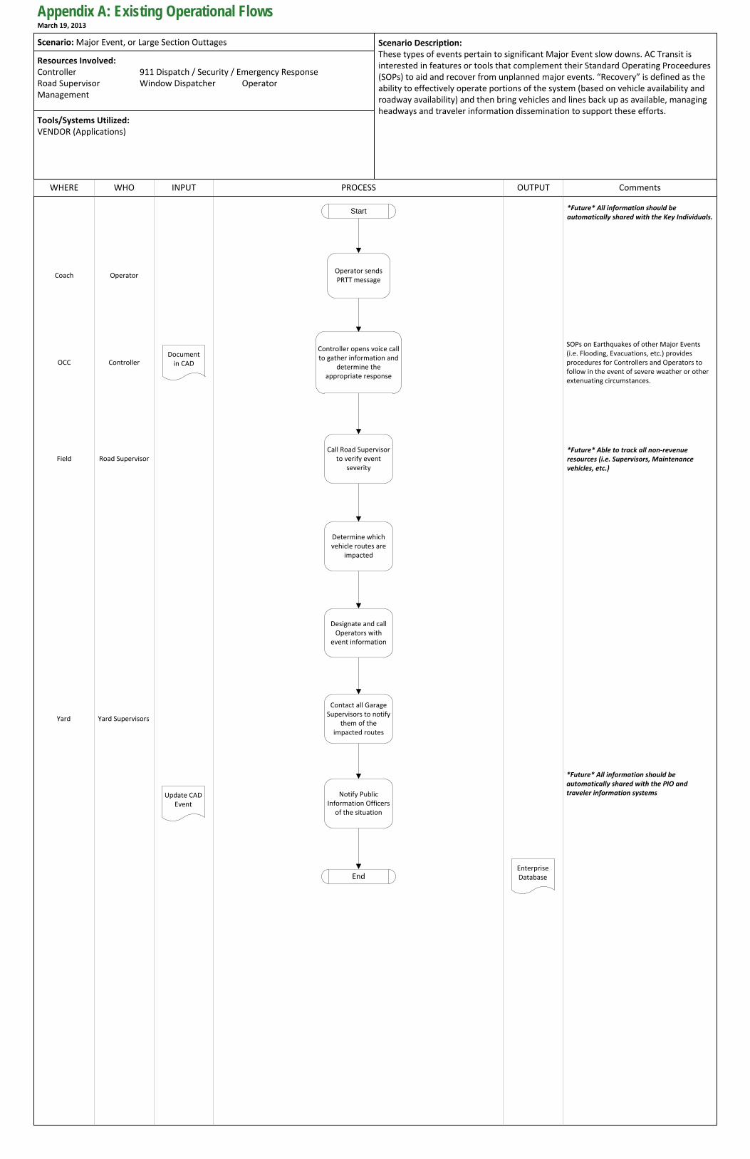
PROCESS OUTPUT CommentsWHERE INPUT
Scenario Description:These types of events pertain to significant Major Event slow downs. AC Transit is interested in features or tools that complement their Standard Operating Proceedures (SOPs) to aid and recover from unplanned major events. “Recovery” is defined as the ability to effectively operate portions of the system (based on vehicle availability and roadway availability) and then bring vehicles and lines back up as available, managing headways and traveler information dissemination to support these efforts.
WHO
Resources Involved:Controller 911 Dispatch / Security / Emergency ResponseRoad Supervisor Window Dispatcher OperatorManagement
Tools/Systems Utilized:VENDOR (Applications)
Scenario: Major Event, or Large Section Outtages
Start
SOPs on Earthquakes of other Major Events (i.e. Flooding, Evacuations, etc.) provides procedures for Controllers and Operators to follow in the event of severe weather or other extenuating circumstances.
Enterprise DatabaseEnd
Document in CAD
Update CAD Event
*Future* Able to track all non-revenue resources (i.e. Supervisors, Maintenance vehicles, etc.)
*Future* All information should be automatically shared with the Key Individuals.
*Future* All information should be automatically shared with the PIO and traveler information systems
Operator sends PRTT message
Controller opens voice call to gather information and
determine the appropriate response
Call Road Supervisor to verify event
severity
Determine which vehicle routes are
impacted
Designate and call Operators with
event information
Contact all Garage Supervisors to notify
them of the impacted routes
Notify Public Information Officers
of the situation
Coach Operator
OCC Controller
Field Road Supervisor
Yard Yard Supervisors
Appendix A: Existing Operational FlowsMarch 19, 2013
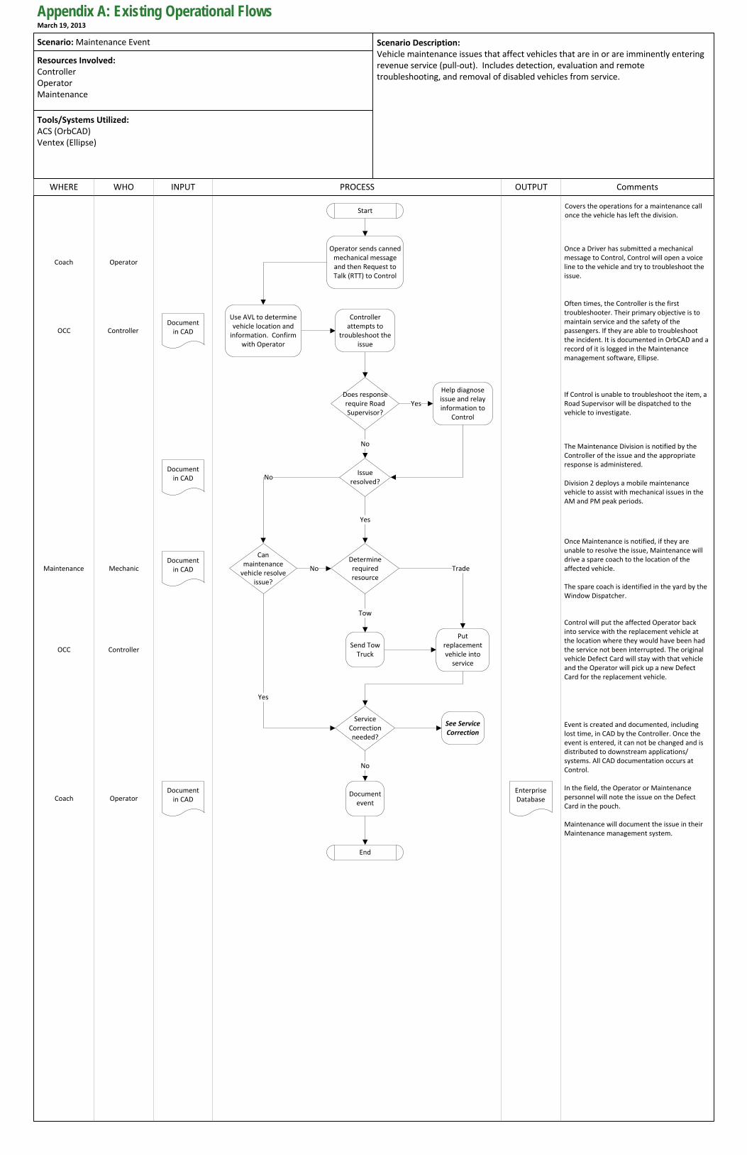
PROCESS OUTPUT CommentsWHERE INPUT
Scenario Description:Vehicle maintenance issues that affect vehicles that are in or are imminently entering revenue service (pull-out). Includes detection, evaluation and remote troubleshooting, and removal of disabled vehicles from service.
WHO
Resources Involved:ControllerOperatorMaintenance
Tools/Systems Utilized:ACS (OrbCAD)Ventex (Ellipse)
Scenario: Maintenance Event
Start
Determine required resource
No
Can maintenance
vehicle resolve issue?
End
Covers the operations for a maintenance call once the vehicle has left the division.
Once a Driver has submitted a mechanical message to Control, Control will open a voice line to the vehicle and try to troubleshoot the issue.
The Maintenance Division is notified by the Controller of the issue and the appropriate response is administered.
Event is created and documented, including lost time, in CAD by the Controller. Once the event is entered, it can not be changed and is distributed to downstream applications/systems. All CAD documentation occurs at Control.
In the field, the Operator or Maintenance personnel will note the issue on the Defect Card in the pouch.
Maintenance will document the issue in their Maintenance management system.
No
Yes
Once Maintenance is notified, if they are unable to resolve the issue, Maintenance will drive a spare coach to the location of the affected vehicle.
The spare coach is identified in the yard by the Window Dispatcher.
Control will put the affected Operator back into service with the replacement vehicle at the location where they would have been had the service not been interrupted. The original vehicle Defect Card will stay with that vehicle and the Operator will pick up a new Defect Card for the replacement vehicle.
Operator sends canned mechanical message and then Request to Talk (RTT) to Control
Use AVL to determine vehicle location and
information. Confirm with Operator
Help diagnose issue and relay information to
Control
Send Tow Truck
Document event
Put replacement vehicle into
service
Document in CAD
Trade
Coach Operator
OCC Controller
Maintenance Mechanic
Coach Operator
OCC Controller
Often times, the Controller is the first troubleshooter. Their primary objective is to maintain service and the safety of the passengers. If they are able to troubleshoot the incident. It is documented in OrbCAD and a record of it is logged in the Maintenance management software, Ellipse.
Enterprise Database
Document in CAD
Does response require Road Supervisor?
Yes
Tow
If Control is unable to troubleshoot the item, a Road Supervisor will be dispatched to the vehicle to investigate.
Division 2 deploys a mobile maintenance vehicle to assist with mechanical issues in the AM and PM peak periods.
Controller attempts to
troubleshoot the issue
No
Issue resolved?
Yes
Document in CAD
Service Correction needed?
No
See Service Correction
Document in CAD
Appendix A: Existing Operational FlowsMarch 19, 2013

PROCESS OUTPUT CommentsWHERE INPUT
Scenario Description:This scenario involves the use of archived real-time operational data to support service planning functions including scheduling and schedule adjustments, performance monitoring, ridership analysis, and other tactical and long-range planning functions. These planning activities utilize data collected onboard vehicles as well as CAD data as part of a “feedback” process that supports continual system improvement and adaptation to changing circumstances. The planning function also supports pre-emptive preparation for emergency and incident scenario response, such as bus bridging.
WHO
Resources Involved:WHERE (WHO)
Tools/Systems Utilized:VENDOR (Applications)
Scenario: Planning / Scheduleing
End
Real time CAD data is “cleaned”, matched to schedules
Planning uses data collected on the
vehicle to run Performance Summaries
Existing data is used by various other
departments (Managers, TIC, etc.) for reporting,
analysis, and other various means
Planning generates Trip Stop Summary (Ridership Reports) & Run Trip Analysis
Daily/Weekly Schedule
adjustment
New schedules are loaded into the
Enterprise Tables and uploaded onto
the BDS cards
Start
One of the largest concerns for the Planning department is to maintain the current reliability and types of data that are currently being captured.
The Planning department generally focuses on how to improve performance. They currently use multiple programs to accomplish this.
Data collected includes:- Door Opens- Door Closes- APC Data (17% of fleet equipped)
Appendix A: Existing Operational FlowsMarch 19, 2013


MAPPING ENTERPRISE GOALS TO KEY CAPABILITIES
APPENDIX B


Appendix B: Mapping of Workshop Needs to Goals March 19, 2013
1
AC Transit Goals to Activity Mapping
Enterprise Goal1. Better service management
Enterprise Goal2. Better fleet performance
Enterprise Goal3. Better customer experience
Enterprise Goal4. Better operational plans and schedules
has part
«Enterprise»
Concept Activity1. Capture internal and external system
information
Concept Activity2. Integrate information on-board and at the
central system
Concept Activity3. Distribute information between the on-
board, central, and external nodes
Concept Activity4. Support and maintain the new system
supports(all)
CapabilityImproved service monitoring
CapabilityImproved service regulation
CapabilityImproved asset maintenance
CapabilityImproved asset management
CapabilityImproved accuracy, quality, and timeliness
of information to the traveling public
CapabilityImproved analysis of historic service data
requires
requires
requires
requires
requires
requires
requires
Enterprise GoalProvide an integrated service and fleet management system that advances AC Transit staff and customers’ ability to make safer, more reliable, and more timely transit service decisions
aspires to
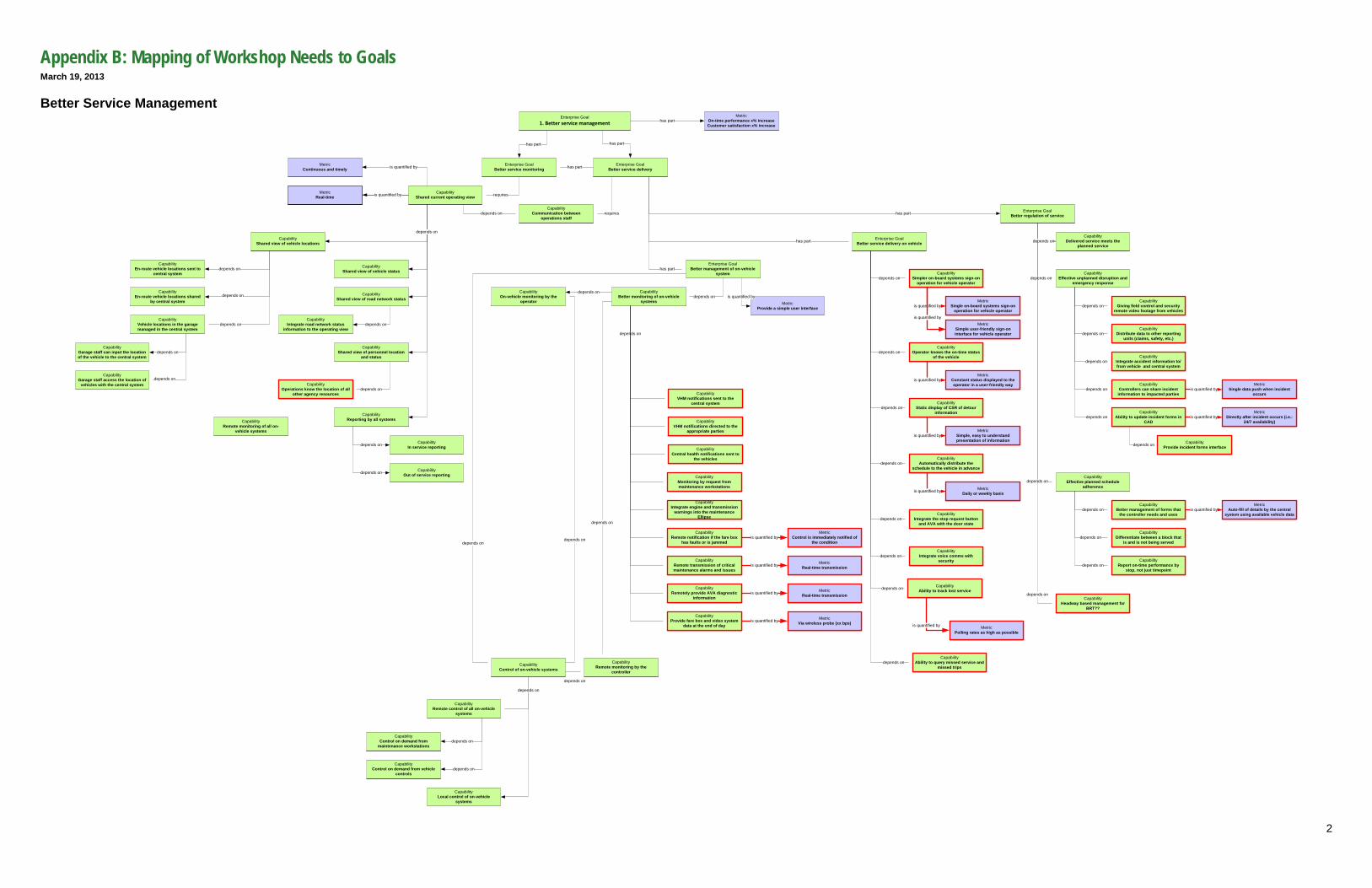
Appendix B: Mapping of Workshop Needs to Goals March 19, 2013
2
Better Service Management Enterprise Goal
1. Better service management
Enterprise GoalBetter service monitoring
has part
Enterprise GoalBetter service delivery
has part
CapabilityShared current operating view
MetricReal-time is quantified by
CapabilityCommunication between
operations staff
Enterprise GoalBetter regulation of servicehas part
Enterprise GoalBetter service delivery on vehicle
CapabilityShared view of vehicle locations
CapabilityShared view of vehicle status
CapabilityShared view of road network status
Enterprise GoalBetter management of on-vehicle
system
CapabilityBetter monitoring of on-vehicle
systems
CapabilityControl of on-vehicle systems
CapabilityOn-vehicle monitoring by the
operator
CapabilityRemote monitoring by the
controller
depends on
depends on
depends on
depends on
depends on
depends on
has part
has partCapability
Simpler on-board systems sign-on operation for vehicle operator
MetricSingle on-board systems sign-on
operation for vehicle operator
MetricSimple user-friendly sign-on interface for vehicle operator
is quantified by
is quantified by
CapabilityOperator knows the on-time status
of the vehicle
MetricConstant status displayed to the operator in a user-friendly way
is quantified by
CapabilityStatic display of CSR of detour
information
MetricSimple, easy to understand presentation of information
is quantified by
CapabilityAutomatically distribute the
schedule to the vehicle in advance
MetricDaily or weekly basisis quantified by
CapabilityIntegrate the stop request button
and AVA with the door state
CapabilityIntegrate voice comms with
security
depends on
depends on
depends on
depends on
depends on
depends on
CapabilityEffective planned schedule
adherence
CapabilityEffective unplanned disruption and
emergency response
CapabilityBetter management of forms that
the controller needs and usesdepends on
MetricAuto-fill of details by the central
system using available vehicle datais quantified by
CapabilityDifferentiate between a block that
is and is not being served
CapabilityIntegrate accident information to/from vehicle and central system
depends on
CapabilityControllers can share incident information to impacted parties
depends onMetric
Single data push when incident occurs
is quantified by
depends on
CapabilityHeadway based management for
BRT??
CapabilityReport on-time performance by
stop, not just timepointdepends on
CapabilityAbility to update incident forms in
CAD
MetricDirectly after incident occurs (i.e.:
24/7 availability)is quantified by
CapabilityProvide incident forms interface
depends on
depends on
CapabilityGiving field control and security
remote video footage from vehicles
depends on
depends on
CapabilityDistribute data to other reporting
units (claims, safety, etc.)
depends on
depends on
MetricOn-time performance x% increaseCustomer satisfaction x% increase
has part
requires
requiresdepends on
CapabilityIntegrate road network status
information to the operating viewdepends on
CapabilityDelivered service meets the
planned servicedepends on
has part
depends on
CapabilityShared view of personnel location
and status
depends on
CapabilityEn-route vehicle locations sent to
central system
CapabilityVehicle locations in the garage managed in the central system
depends on
depends on
CapabilityEn-route vehicle locations shared
by central systemdepends on
CapabilityGarage staff can input the location of the vehicle to the central system
CapabilityGarage staff access the location of
vehicles with the central system
depends on
depends on
MetricProvide a simple user interface
is quantified by
CapabilityOperations know the location of all
other agency resourcesdepends on
MetricContinuous and timely is quantified by
CapabilityAbility to track lost service
MetricPolling rates as high as possible
is quantified by
depends onCapability
Ability to query missed service and missed trips
depends on
CapabilityVHM notifications sent to the
central system
CapabilityVHM notifications directed to the
appropriate parties
CapabilityCentral health notifications sent to
the vehicles
depends on
CapabilityRemote monitoring of all on-
vehicle systems
CapabilityRemote control of all on-vehicle
systems
CapabilityMonitoring by request from maintenance workstations
CapabilityControl on demand from
maintenance workstationsdepends on
CapabilityIntegrate engine and transmission
warnings into the maintenance Ellipse
CapabilityRemote notification if the fare box
has faults or is jammed
MetricControl is immediately notified of
the conditionis quantified by
CapabilityRemote transmission of critical maintenance alarms and issues
MetricReal-time transmissionis quantified by
CapabilityRemotely provide AVA diagnostic
information
MetricReal-time transmissionis quantified by
CapabilityProvide fare box and video system
data at the end of day
MetricVia wireless probe (xx bps)is quantified by
CapabilityReporting by all systems
CapabilityIn service reportingdepends on
CapabilityOut of service reportingdepends on
depends on
CapabilityControl on demand from vehicle
controlsdepends on
CapabilityLocal control of on-vehicle
systems
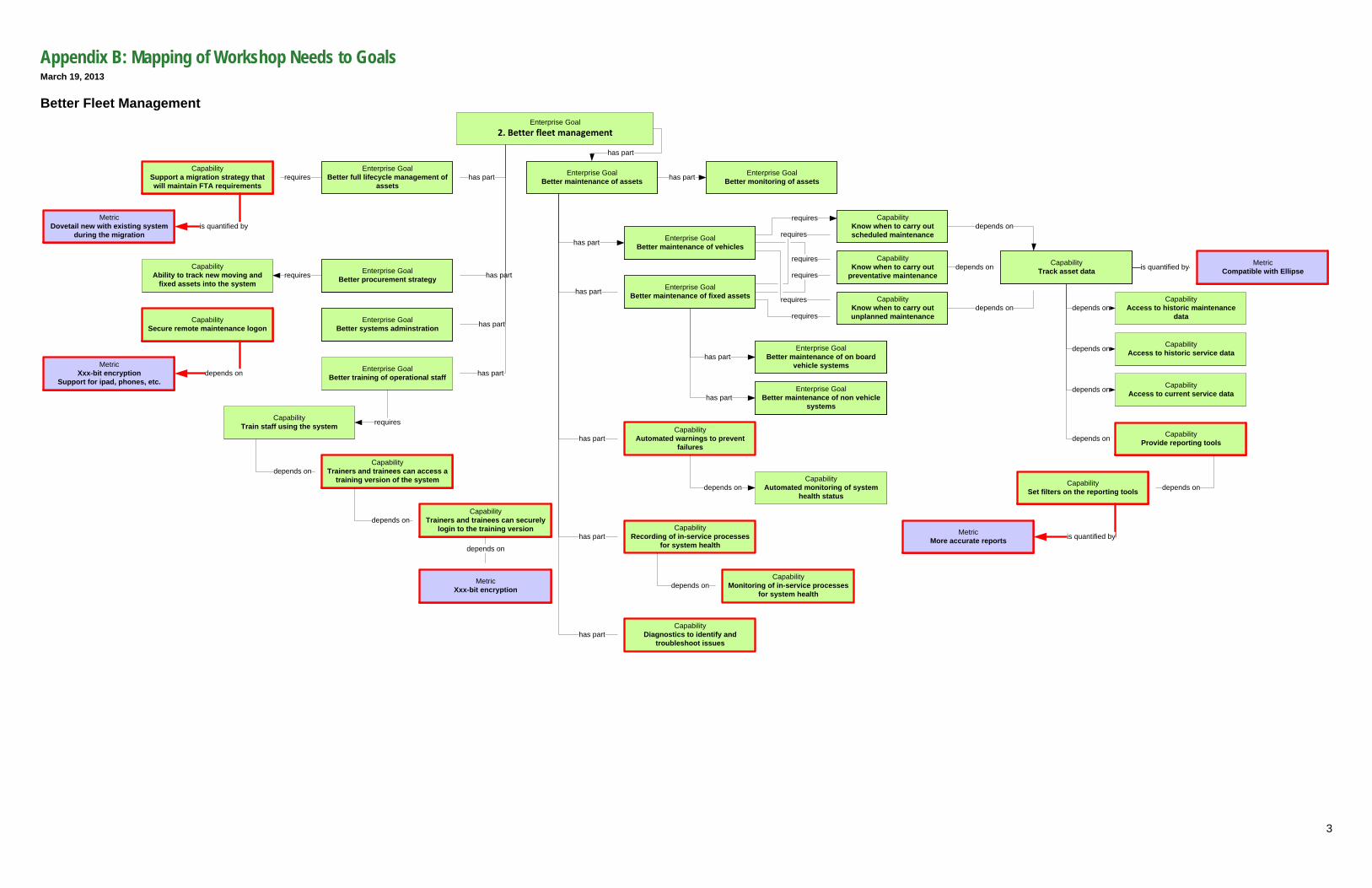
Appendix B: Mapping of Workshop Needs to Goals March 19, 2013
3
Better Fleet Management Enterprise Goal
2. Better fleet management
Enterprise GoalBetter maintenance of vehicles
Enterprise GoalBetter procurement strategy
Enterprise GoalBetter full lifecycle management of
assets
has part
has part
has part Enterprise GoalBetter maintenance of assets
Enterprise GoalBetter maintenance of fixed assets
has part
has part
Enterprise GoalBetter maintenance of on board
vehicle systemshas part
CapabilityTrack asset data
depends on
depends on
depends on
CapabilityKnow when to carry out scheduled maintenance
CapabilityKnow when to carry out
preventative maintenance
CapabilityKnow when to carry out unplanned maintenance
Enterprise GoalBetter maintenance of non vehicle
systemshas part
Enterprise GoalBetter systems adminstration
requires
requires
requires
requires
requires
requireshas part
CapabilityAccess to historic service datadepends on
CapabilityAccess to historic maintenance
datadepends on
CapabilityAccess to current service datadepends on
CapabilityAbility to track new moving and
fixed assets into the systemrequires
Enterprise GoalBetter training of operational staff
CapabilityTrain staff using the system requires
has part
CapabilityTrainers and trainees can access a
training version of the systemdepends on
CapabilityTrainers and trainees can securely
login to the training versiondepends on
MetricXxx-bit encryption
depends on
CapabilityAutomated warnings to prevent
failures
CapabilityAutomated monitoring of system
health statusdepends on
has part
CapabilityRecording of in-service processes
for system health
CapabilityMonitoring of in-service processes
for system healthdepends on
CapabilityDiagnostics to identify and
troubleshoot issues
Enterprise GoalBetter monitoring of assetshas part
has part
has part
CapabilityProvide reporting tools
CapabilitySet filters on the reporting tools depends on
MetricMore accurate reports is quantified by
depends on
CapabilitySecure remote maintenance logon
MetricXxx-bit encryption
Support for ipad, phones, etc.depends on
CapabilitySupport a migration strategy that will maintain FTA requirements
MetricDovetail new with existing system
during the migrationis quantified by
requires
MetricCompatible with Ellipseis quantified by
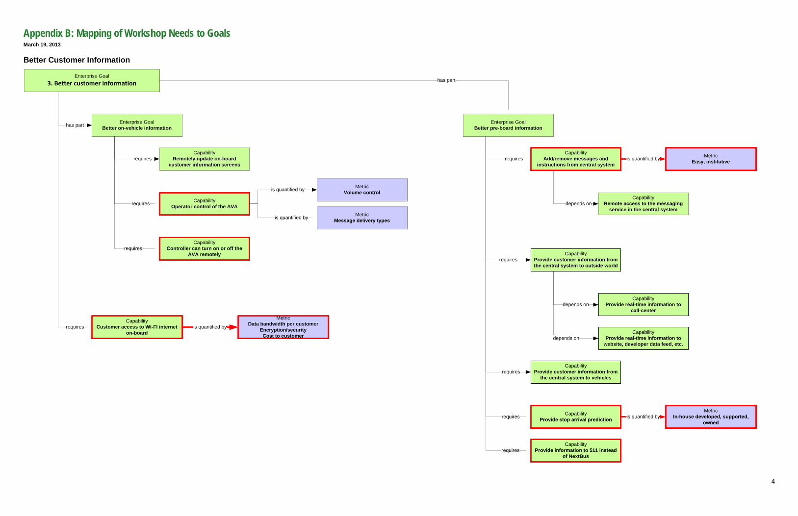
Appendix B: Mapping of Workshop Needs to Goals March 19, 2013
4
Better Customer Information
CapabilityRemotely update on-board
customer information screens
Enterprise Goal3. Better customer information
has part
CapabilityProvide customer information from the central system to outside world
requires
CapabilityProvide customer information from
the central system to vehiclesrequires
Enterprise GoalBetter on-vehicle information
requires
requires
MetricEasy, institutiveis quantified by
Enterprise GoalBetter pre-board information
CapabilityOperator control of the AVA
MetricVolume control
MetricMessage delivery types
is quantified by
is quantified by
CapabilityController can turn on or off the
AVA remotelyrequires
CapabilityAdd/remove messages and
instructions from central systemrequires
CapabilityRemote access to the messaging
service in the central systemdepends on
has part
CapabilityCustomer access to WI-FI internet
on-boardrequires
MetricData bandwidth per customer
Encryption/securityCost to customer
is quantified by
CapabilityProvide stop arrival prediction
MetricIn-house developed, supported,
ownedis quantified byrequires
CapabilityProvide information to 511 instead
of NextBusrequires
CapabilityProvide real-time information to
call-centerdepends on
CapabilityProvide real-time information to
website, developer data feed, etc.depends on
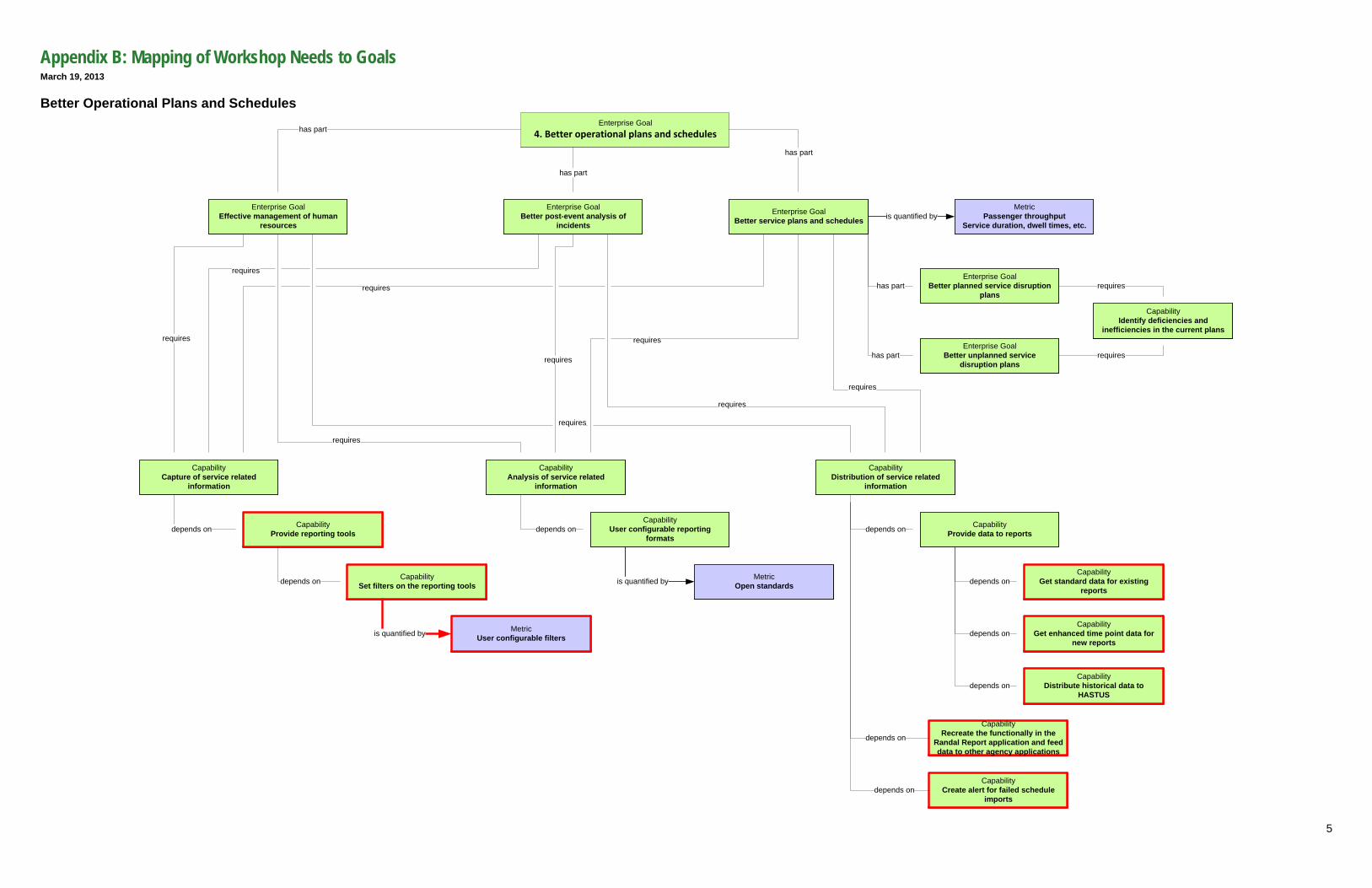
Appendix B: Mapping of Workshop Needs to Goals March 19, 2013
5
Better Operational Plans and Schedules
CapabilityProvide data to reports
CapabilityGet standard data for existing
reportsdepends on
depends on
CapabilityGet enhanced time point data for
new reportsdepends on
CapabilityDistribute historical data to
HASTUSdepends on
depends on
CapabilityCreate alert for failed schedule
importsdepends on
Enterprise Goal4. Better operational plans and schedules
Enterprise GoalBetter service plans and schedules
MetricPassenger throughput
Service duration, dwell times, etc.is quantified by
Enterprise GoalBetter planned service disruption
plans
Enterprise GoalBetter unplanned service
disruption plans
Enterprise GoalBetter post-event analysis of
incidents
CapabilityIdentify deficiencies and
inefficiencies in the current plans
CapabilityCapture of service related
information
CapabilityAnalysis of service related
information
CapabilityDistribution of service related
information
CapabilityUser configurable reporting
formats
MetricOpen standardsis quantified by
requires
Enterprise GoalEffective management of human
resources
CapabilityProvide reporting tools
CapabilitySet filters on the reporting toolsdepends on
MetricUser configurable filtersis quantified by
depends on
CapabilityRecreate the functionally in the
Randal Report application and feed data to other agency applications
depends on
has part
has part
has part
has part
has part
requires
requires
requires
requires
requires
requires
requires
requires
requires
requires