Embed Size (px)
Citation preview
LB0044-05GB Revised 07.03.2003
JVL Industri Elektronik A/S
AMC20 / AMC21AMC22
AndAMC20P / AMC21P
AMC22P
AC-Servo Motor ControllerUser Manual

Copyright 1998-2003, JVL Industri Elektronik A/S. All rights reserved.This user manual must not be reproduced in any form without prior written permission of JVL Industri Elektronik A/S.JVL Industri Elektronik A/S reserves the right to make changes to informa-tion contained in this manual without prior notice. Similarly JVL Industri Elektronik A/S assumes no liability for printing errors or other omissions or discrepancies in this user manual.
MotoWare is a registered trademark
JVL Industri Elektronik A/SBlokken 42
DK-3460 BirkerødDenmark
Tlf. +45 45 82 44 40Fax. +45 45 82 55 50
e-mail: [email protected]: http://www.jvl.dk
JVL Industri Elektronik A/S - User Manual - AC Servo Controller AMC20/21/22
Contents1 Introduction .................................................................................................................... 11.1 Features ........................................................................................................................................................................21.2 Controller Front Panel ..................................................................................................................................................31.3 Overview of Operating Modes .....................................................................................................................................41.4 Getting Started — Gear Mode (Mode 1) ......................................................................................................................51.5 Getting Started — Positioning Mode (Mode 2) ............................................................................................................61.6 Getting Started — Register Mode (Mode 3) .................................................................................................................71.7 Getting Started — Velocity Mode (Mode 4) .................................................................................................................81.8 Getting Started — Torque Mode (Mode 5) ..................................................................................................................9
2 Installation and Adjustment ......................................................................................... 112.1 General Aspects of Installation ....................................................................................................................................122.2 Transfer of Parameters to the Controller ...................................................................................................................132.3 Current filter optimizing .............................................................................................................................................162.4 Adjustment of Servo Regulation ..................................................................................................................................182.5 Adjustment of BIAS .....................................................................................................................................................22
3 Hardware ...................................................................................................................... 233.1 Connections ................................................................................................................................................................243.2 Power Supply ..............................................................................................................................................................253.3 Motor Connection ......................................................................................................................................................273.4 Encoder Input .............................................................................................................................................................293.5 Hall Input .....................................................................................................................................................................313.6 Servo On Input (SON) ................................................................................................................................................323.7 User Inputs ..................................................................................................................................................................333.8 End-of-travel Limit Inputs ...........................................................................................................................................343.9 Home (Reset) Input ....................................................................................................................................................353.10 User Outputs ..............................................................................................................................................................363.11 Pulse Inputs .................................................................................................................................................................373.12 Pulse Outputs ..............................................................................................................................................................403.13 Analogue Inputs ...........................................................................................................................................................413.14 Power Dump Output ..................................................................................................................................................423.15 RS232 Interface ...........................................................................................................................................................433.16 RS485 Interface ...........................................................................................................................................................463.17 JVL-Bus Interface in the AMC2xP ...............................................................................................................................47
4 Software ........................................................................................................................ 494.1 Use of RS232 Commands ...........................................................................................................................................504.2 Operating Modes - General Description ....................................................................................................................514.3 Gear Mode (MO=1) ...................................................................................................................................................524.4 Positioning Mode (MO=2) .........................................................................................................................................534.5 Register Mode (MO=3) ..............................................................................................................................................544.6 Velocity Mode (MO=4) ..............................................................................................................................................594.7 Torque Mode (MO=5) ...............................................................................................................................................604.8 Program Execution in the AMC2xP ............................................................................................................................614.9 Mechanical Reset .........................................................................................................................................................754.10 Adjustment of Analogue Input .....................................................................................................................................784.11 Command Description ................................................................................................................................................794.12 Error Messages .........................................................................................................................................................1674.13 Alphabetical Overview of Commands ......................................................................................................................176
5 Appendix ..................................................................................................................... 1815.1 Technical Data ..........................................................................................................................................................1825.2 Physical Dimensions ..................................................................................................................................................1835.3 Power Dissipation .....................................................................................................................................................1855.4 Servo Loop ................................................................................................................................................................1865.5 Error Indication .........................................................................................................................................................1875.6 Typical Errors ............................................................................................................................................................1885.7 Connection of an Unknown Motor Type .................................................................................................................1905.8 Examples of Motor Connection ................................................................................................................................2005.9 Using Linear Motors ..................................................................................................................................................2055.10 Typical Applications ..................................................................................................................................................2065.11 Accessories ...............................................................................................................................................................207

JVL Industri Elektronik A/S - User Manual - AC Servo Controller AMC20/21/22

JVL Industri Elektronik A/S - User Manual - AC Servo Controller AMC20/21/22 1
1 Introduction
2 JVL Industri Elektronik A/S - User Manual - AC Servo Controller AMC20/21/22
1.1 Features
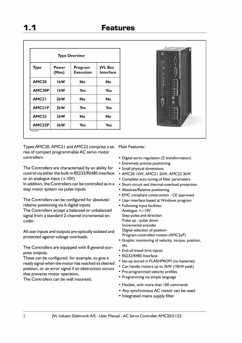
Types AMC20, AMC21 and AMC22 comprise a se-ries of compact programmable AC servo motor controllers.
The Controllers are characterised by an ability for control via either the built-in RS232/RS485 interface or an analogue input (±10V).In addition, the Controllers can be controlled as in a step motor system via pulse inputs.
The Controllers can be configured for absolute/-relative positioning via 6 digital inputs.The Controllers accept a balanced or unbalanced signal from a standard 2-channel incremental en-coder.
All user inputs and outputs are optically isolated and protected against voltage overloads.
The Controllers are equipped with 8 general-pur-pose outputs.These can be configured, for example, to give a ready signal when the motor has reached its desired position, or an error signal if an obstruction occurs that prevents motor operation. The Controllers can be wall mounted.
Main Features:
• Digital servo regulation (Z transformation)• Extremely precise positioning• Small physical dimensions• AMC20 1kW, AMC21 2kW, AMC22 3kW• Complete auto tuning of filter parameters• Short-circuit and thermal-overload protection• Absolute/Relative positioning• EMC compliant construction - CE approved• User interface based at Windows program• Following input facilities:
Analogue +/-10VStep-pulse and directionPulse up - pulse downIncremental encoderDigital selection of positionProgram-controlled motion (AMC2xP)
• Graphic monitoring of velocity, torque, position, etc.
• End-of-travel limit inputs• RS232/R485 Interface• Set-up stored in FLASHPROM (no batteries)• Can handle motors up to 3kW (10kW peak)• Pre-programmed velocity profiles• Programming via simple language
• Flexible, with more than 100 commands• Any synchronous AC motor can be used• Integrated mains supply filter
AMC20
Type Power(Max)
Type Overview
ProgramExecution
JVL BusInterface
AMC20P
AMC21
AMC21P
AMC22
AMC22P
1kW
1kW
2kW
2kW
3kW
3kW
No
Yes
Yes
Yes
Yes
Yes
Yes
No
No
No
No
No
TT0528GB
JVL Industri Elektronik A/S - User Manual - AC Servo Controller AMC20/21/22 3
1.2 Controller Front Panel
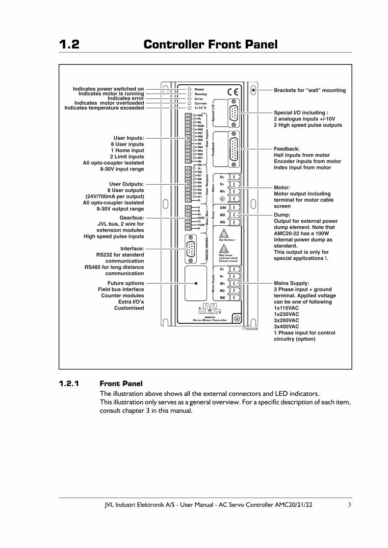
1.2.1 Front PanelThe illustration above shows all the external connectors and LED indicators.This illustration only serves as a general overview. For a specific description of each item, consult chapter 3 in this manual.
!
Brackets for "wall" mounting
Special I/O including :2 analogue inputs +/-10V2 High speed pulse outputs
Feedback:Hall inputs from motorEncoder inputs from motorIndex input from motor
Motor:Motor output includingterminal for motor cable screen
Dump:Output for external powerdump element. Note thatAMC20-22 has a 100Winternal power dump asstandard.This output is only forspecial applications !.
Mains Supply:3 Phase input + groundterminal. Applied voltagecan be one of following1x115VAC1x230VAC3x200VAC3x400VAC1 Phase input for controlcircuitry (option)
Interface:RS232 for standard
communicationRS485 for long distance
communication
Future optionsField bus interface
Counter modulesExtra I/O's
Customised
Gear/bus:JVL bus, 2 wire for extension modules
High speed pulse inputs
User Outputs:8 User outputs
(24V/700mA per output)All opto-coupler isolated
8-30V output range
User Inputs:8 User inputs1 Home input2 Limit inputs
All opto-coupler isolated8-30V input range
Indicates temperature exceededIndicates motor overloaded
Indicates errorIndicates motor is running
Indicates power switched on
TT0502GB
4 JVL Industri Elektronik A/S - User Manual - AC Servo Controller AMC20/21/22
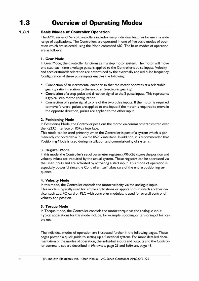
1.3 Overview of Operating Modes1.3.1 Basic Modes of Controller Operation
The AMC series of Servo Controllers includes many individual features for use in a wide range of applications. The Controllers are operated in one of five basic modes of oper-ation which are selected using the Mode command MO. The basic modes of operation are as follows:
1. Gear ModeIn Gear Mode, the Controller functions as in a step motor system. The motor will move one step each time a voltage pulse is applied to the Controller’s pulse inputs. Velocity and acceleration/deceleration are determined by the externally applied pulse frequency.Configuration of these pulse inputs enables the following:
• Connection of an incremental encoder so that the motor operates at a selectable gearing ratio in relation to the encoder (electronic gearing).
• Connection of a step-pulse and direction signal to the 2 pulse inputs. This represents a typical step motor configuration.
• Connection of a pulse signal to one of the two pulse inputs. If the motor is required to move forward, pulses are applied to one input; if the motor is required to move in the opposite direction, pulses are applied to the other input.
2. Positioning ModeIn Positioning Mode, the Controller positions the motor via commands transmitted over the RS232 interface or RS485 interface.This mode can be used primarily when the Controller is part of a system which is per-manently connected to a PC via the RS232 interface. In addition, it is recommended that Positioning Mode is used during installation and commissioning of systems.
3. Register ModeIn this mode, the Controller’s set of parameter registers (X0-X63) store the position and velocity values etc. required by the actual system. These registers can be addressed via the User Inputs and are activated by activating a start input. This mode of operation is especially powerful since the Controller itself takes care of the entire positioning se-quence.
4. Velocity ModeIn this mode, the Controller controls the motor velocity via the analogue input.This mode is typically used for simple applications or applications in which another de-vice, such as a PC-card or PLC with controller modules, is used for overall control of velocity and position.
5. Torque ModeIn Torque Mode, the Controller controls the motor torque via the analogue input.Typical applications for this mode include, for example, spooling or tensioning of foil, ca-ble etc.
The individual modes of operation are illustrated further in the following pages. These pages provide a quick guide to setting up a functional system. For more detailed docu-mentation of the modes of operation, the individual inputs and outputs and the Control-ler command set are described in Hardware, page 23 and Software, page 49.
JVL Industri Elektronik A/S - User Manual - AC Servo Controller AMC20/21/22 5
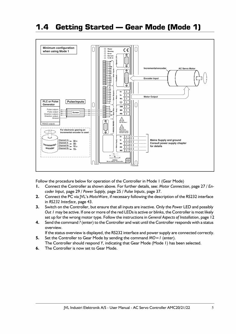
1.4 Getting Started — Gear Mode (Mode 1)
Follow the procedure below for operation of the Controller in Mode 1 (Gear Mode)1. Connect the Controller as shown above. For further details, see: Motor Connection, page 27 / En-
coder Input, page 29 / Power Supply, page 25 / Pulse Inputs, page 37.2. Connect the PC via JVL’s MotoWare, if necessary following the description of the RS232 interface
in RS232 Interface, page 43.3. Switch on the Controller, but ensure that all inputs are inactive. Only the Power LED and possibly
Out 1 may be active. If one or more of the red LEDs is active or blinks, the Controller is most likely set up for the wrong motor type. Follow the instructions in General Aspects of Installation, page 12
4. Send the command ? (enter) to the Controller and wait until the Controller responds with a status overview.If the status overview is displayed, the RS232 interface and power supply are connected correctly.
5. Set the Controller to Gear Mode by sending the command MO=1 (enter).The Controller should respond Y, indicating that Gear Mode (Mode 1) has been selected.
6. The Controller is now set to Gear Mode.
!
Mains Supply and groundConsult power supply chapterfor details
TT0550GB
AC Servo Motor
Pulse Inputs
For electronic gearing anincremental encoder is used
Pulse output+
PLC or PulseGenerator
RS422 outputs
Direction output+Direction output-
Ground
Pulse output-
Minimum configuration when using Mode 1
Screen
Incremental encoder
Encoder Input
Motor Output
Channel A+ XI+XI-YI+YI-
Channel A-Channel B+Channel B+
6 JVL Industri Elektronik A/S - User Manual - AC Servo Controller AMC20/21/22
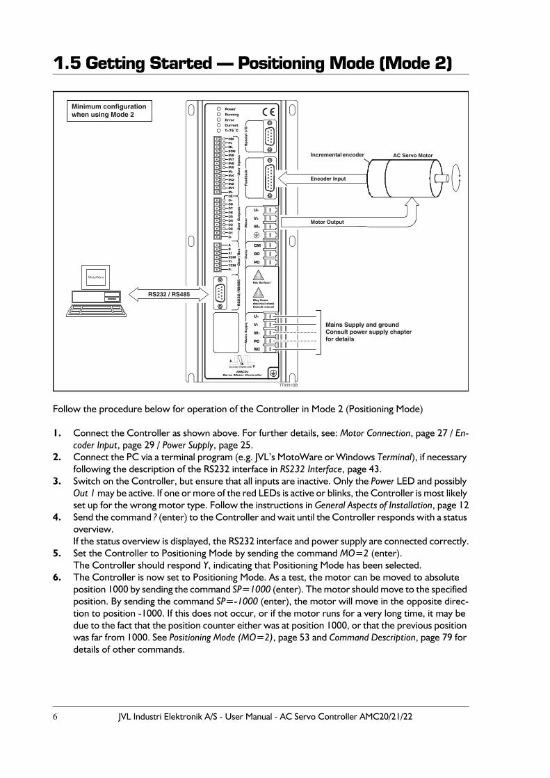
1.5 Getting Started — Positioning Mode (Mode 2)
Follow the procedure below for operation of the Controller in Mode 2 (Positioning Mode)
1. Connect the Controller as shown above. For further details, see: Motor Connection, page 27 / En-coder Input, page 29 / Power Supply, page 25.
2. Connect the PC via a terminal program (e.g. JVL’s MotoWare or Windows Terminal), if necessary following the description of the RS232 interface in RS232 Interface, page 43.
3. Switch on the Controller, but ensure that all inputs are inactive. Only the Power LED and possibly Out 1 may be active. If one or more of the red LEDs is active or blinks, the Controller is most likely set up for the wrong motor type. Follow the instructions in General Aspects of Installation, page 12
4. Send the command ? (enter) to the Controller and wait until the Controller responds with a status overview.If the status overview is displayed, the RS232 interface and power supply are connected correctly.
5. Set the Controller to Positioning Mode by sending the command MO=2 (enter).The Controller should respond Y, indicating that Positioning Mode has been selected.
6. The Controller is now set to Positioning Mode. As a test, the motor can be moved to absolute position 1000 by sending the command SP=1000 (enter). The motor should move to the specified position. By sending the command SP=-1000 (enter), the motor will move in the opposite direc-tion to position -1000. If this does not occur, or if the motor runs for a very long time, it may be due to the fact that the position counter either was at position 1000, or that the previous position was far from 1000. See Positioning Mode (MO=2), page 53 and Command Description, page 79 for details of other commands.
!
Mains Supply and groundConsult power supply chapterfor details
TT0551GB
AC Servo Motor
Minimum configuration when using Mode 2
RS232 / RS485
Incremental encoder
Encoder Input
Motor Output
MotoWare
JVL Industri Elektronik A/S - User Manual - AC Servo Controller AMC20/21/22 7
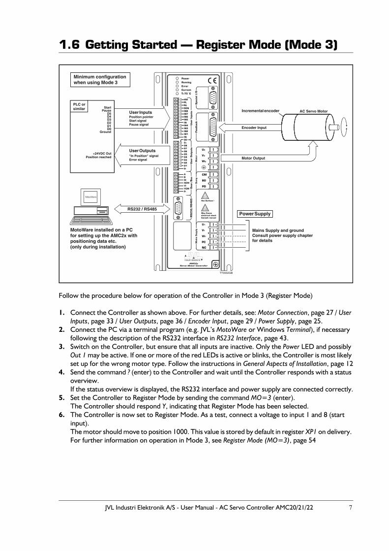
1.6 Getting Started — Register Mode (Mode 3)
Follow the procedure below for operation of the Controller in Mode 3 (Register Mode)
1. Connect the Controller as shown above. For further details, see: Motor Connection, page 27 / User Inputs, page 33 / User Outputs, page 36 / Encoder Input, page 29 / Power Supply, page 25.
2. Connect the PC via a terminal program (e.g. JVL’s MotoWare or Windows Terminal), if necessary following the description of the RS232 interface in RS232 Interface, page 43.
3. Switch on the Controller, but ensure that all inputs are inactive. Only the Power LED and possibly Out 1 may be active. If one or more of the red LEDs is active or blinks, the Controller is most likely set up for the wrong motor type. Follow the instructions in General Aspects of Installation, page 12
4. Send the command ? (enter) to the Controller and wait until the Controller responds with a status overview.If the status overview is displayed, the RS232 interface and power supply are connected correctly.
5. Set the Controller to Register Mode by sending the command MO=3 (enter).The Controller should respond Y, indicating that Register Mode has been selected.
6. The Controller is now set to Register Mode. As a test, connect a voltage to input 1 and 8 (start input).The motor should move to position 1000. This value is stored by default in register XP1 on delivery. For further information on operation in Mode 3, see Register Mode (MO=3), page 54
!
Mains Supply and groundConsult power supply chapterfor details
TT0552GB
AC Servo Motor
Power Supply
Minimum configuration when using Mode 3
RS232 / RS485
User Outputs
User Inputs
PLC orsimilar
Position reached+24VDC Out
GroundD0D1D2D3D4D5
PauseStart
Position pointerStart signalPause signal
"In Position" signalError signal
MotoWare installed on a PCfor setting up the AMC2x withpositioning data etc.(only during installation)
Incremental encoder
Encoder Input
Motor Output
MotoWare
8 JVL Industri Elektronik A/S - User Manual - AC Servo Controller AMC20/21/22
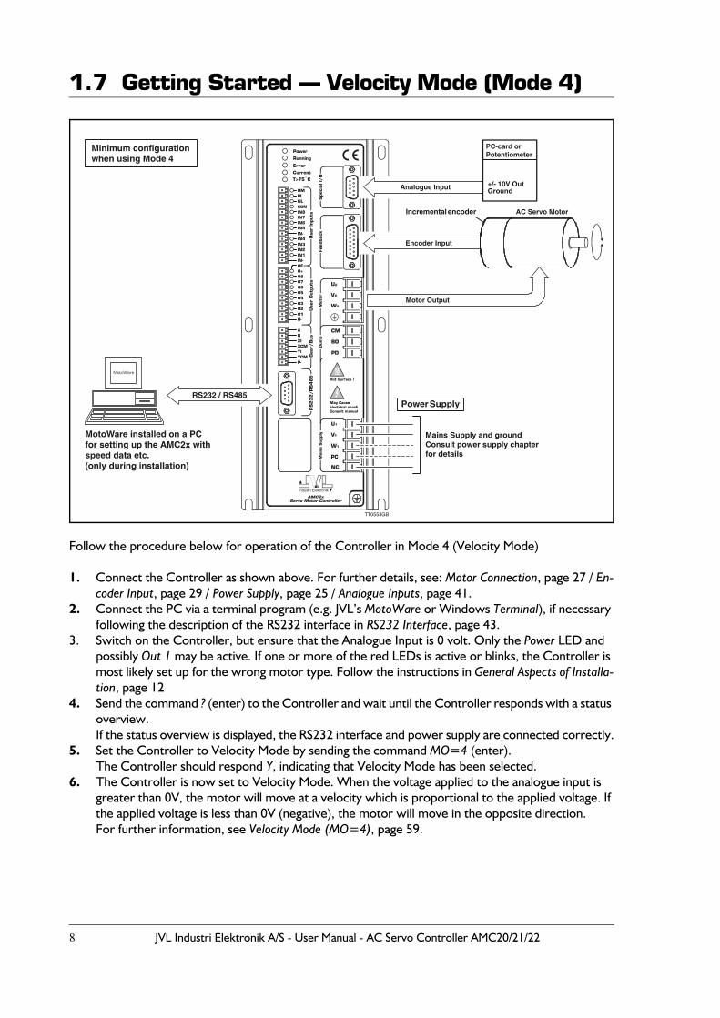
1.7 Getting Started — Velocity Mode (Mode 4)
Follow the procedure below for operation of the Controller in Mode 4 (Velocity Mode)
1. Connect the Controller as shown above. For further details, see: Motor Connection, page 27 / En-coder Input, page 29 / Power Supply, page 25 / Analogue Inputs, page 41.
2. Connect the PC via a terminal program (e.g. JVL’s MotoWare or Windows Terminal), if necessary following the description of the RS232 interface in RS232 Interface, page 43.
3. Switch on the Controller, but ensure that the Analogue Input is 0 volt. Only the Power LED and possibly Out 1 may be active. If one or more of the red LEDs is active or blinks, the Controller is most likely set up for the wrong motor type. Follow the instructions in General Aspects of Installa-tion, page 12
4. Send the command ? (enter) to the Controller and wait until the Controller responds with a status overview.If the status overview is displayed, the RS232 interface and power supply are connected correctly.
5. Set the Controller to Velocity Mode by sending the command MO=4 (enter).The Controller should respond Y, indicating that Velocity Mode has been selected.
6. The Controller is now set to Velocity Mode. When the voltage applied to the analogue input is greater than 0V, the motor will move at a velocity which is proportional to the applied voltage. If the applied voltage is less than 0V (negative), the motor will move in the opposite direction.For further information, see Velocity Mode (MO=4), page 59.
!
Mains Supply and groundConsult power supply chapterfor details
TT0553GB
AC Servo Motor
Power Supply
Minimum configuration when using Mode 4
RS232 / RS485
Analogue Input
MotoWare installed on a PCfor setting up the AMC2x withspeed data etc.(only during installation)
PC-card orPotentiometer
+/- 10V OutGround
Incremental encoder
Encoder Input
Motor Output
MotoWare
JVL Industri Elektronik A/S - User Manual - AC Servo Controller AMC20/21/22 9
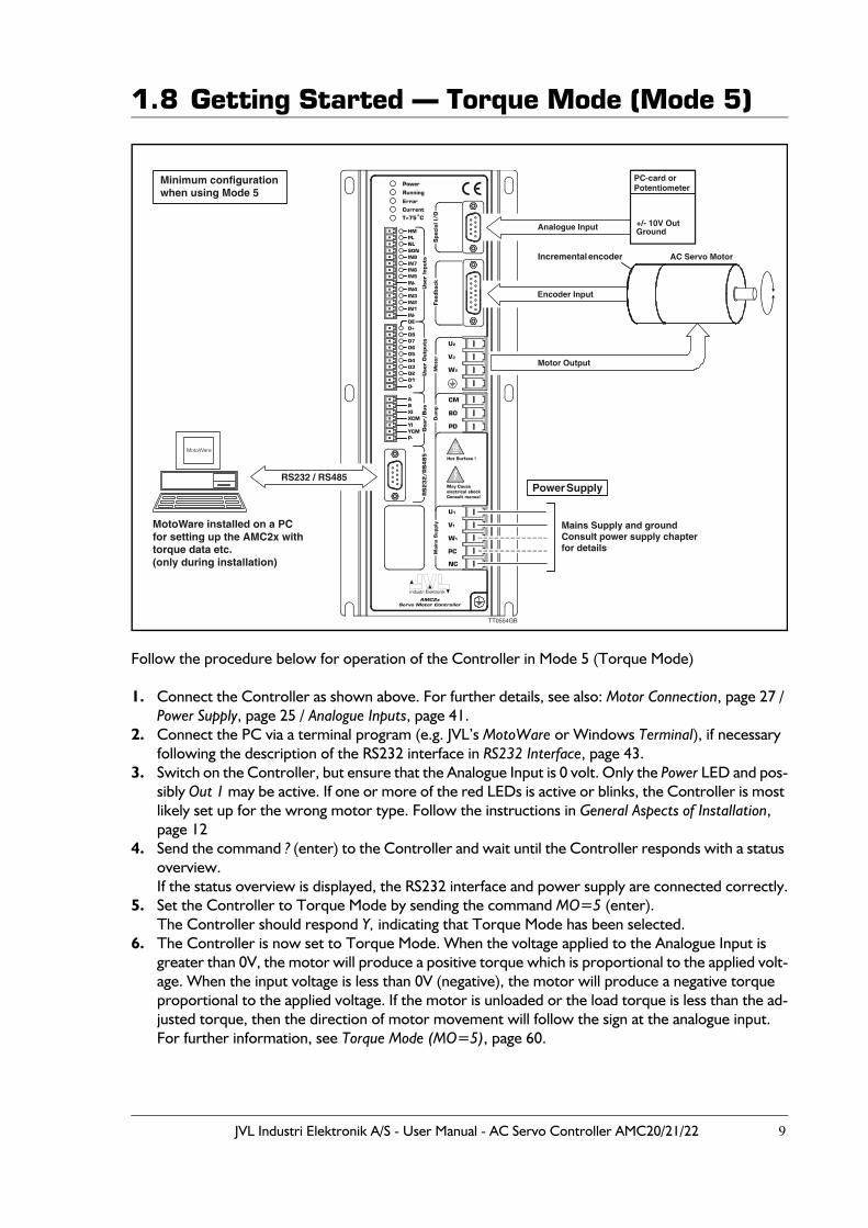
1.8 Getting Started — Torque Mode (Mode 5)
Follow the procedure below for operation of the Controller in Mode 5 (Torque Mode)
1. Connect the Controller as shown above. For further details, see also: Motor Connection, page 27 / Power Supply, page 25 / Analogue Inputs, page 41.
2. Connect the PC via a terminal program (e.g. JVL’s MotoWare or Windows Terminal), if necessary following the description of the RS232 interface in RS232 Interface, page 43.
3. Switch on the Controller, but ensure that the Analogue Input is 0 volt. Only the Power LED and pos-sibly Out 1 may be active. If one or more of the red LEDs is active or blinks, the Controller is most likely set up for the wrong motor type. Follow the instructions in General Aspects of Installation, page 12
4. Send the command ? (enter) to the Controller and wait until the Controller responds with a status overview.If the status overview is displayed, the RS232 interface and power supply are connected correctly.
5. Set the Controller to Torque Mode by sending the command MO=5 (enter).The Controller should respond Y, indicating that Torque Mode has been selected.
6. The Controller is now set to Torque Mode. When the voltage applied to the Analogue Input is greater than 0V, the motor will produce a positive torque which is proportional to the applied volt-age. When the input voltage is less than 0V (negative), the motor will produce a negative torque proportional to the applied voltage. If the motor is unloaded or the load torque is less than the ad-justed torque, then the direction of motor movement will follow the sign at the analogue input.For further information, see Torque Mode (MO=5), page 60.
!
Mains Supply and groundConsult power supply chapterfor details
TT0554GB
AC Servo MotorIncremental encoder
Power Supply
Minimum configuration when using Mode 5
RS232 / RS485
Analogue Input
Encoder Input
Motor Output
MotoWare
MotoWare installed on a PCfor setting up the AMC2x withtorque data etc.(only during installation)
PC-card orPotentiometer
+/- 10V OutGround

10 JVL Industri Elektronik A/S - User Manual - AC Servo Controller AMC20/21/22

JVL Industri Elektronik A/S - User Manual - AC Servo Controller AMC20/21/22 11
2 Installation and Adjustment
12 JVL Industri Elektronik A/S - User Manual - AC Servo Controller AMC20/21/22
2.1 General Aspects of Installation
It is recommended that this section is read carefully in conjunction with the installation of the AC Servo Controller.When the Controller has been installed, the following check-list should be followed:
1. Ensure that the selection of the Controller’s basic mode of operation (1-5) is correct. If necessary, refer to Overview of Operating Modes, page 4, which explains the overall use of the various modes of operation.
2. Connect the motor, encoder, any hall-sensor, diverse end-of-travel inputs, inputs and outputs as required. Details of motor connection, inputs and inputs, powering, etc. are given in Hardware, page 23.Note: For connection of motors and encoders, see the appendix Examples of Motor Connection, page 200, which gives specific connection diagrams for a number of AC servo motors. These sections also give the associated parameter values that the Con-troller should be set to for optimum motor operation.
3. Connect the power to the Controller. Most probably the default parameter settings will not correspond to the actual motor connected. This will result in the Controller reporting an error and current to the motor will be disconnected. If the actual motor used is one of the types named in the Appendix (Examples of Motor Connection, page 200) or included in MotoWare’s parameter list, these parameter val-ues must be transferred to the Controller. See Transfer of Parameters to the Control-ler, page 13.If the motor is recognised, the system should function optimally after transfer of the associated parameter set. Some fine adjustment may be carried out as described in this chapter. The basic installation of the Controller is now complete and the specific function of the Controller can now be set up and tested. See the description of Modes 1 to 5 in the Software section, pages 52 to 60, depending on the required mode of operation. To optimise the complete system, follow the instructions given in Adjustment of Servo Regulation, page 18. If the motor is not recognised, follow the instructions given in Connection of an Un-known Motor Type, page 190.
JVL Industri Elektronik A/S - User Manual - AC Servo Controller AMC20/21/22 13
2.2 Transfer of Parameters to the Controller
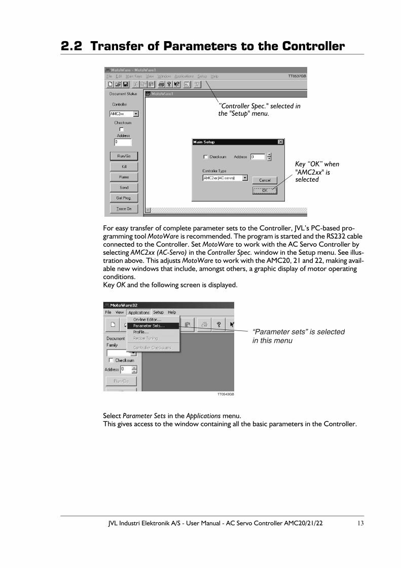
For easy transfer of complete parameter sets to the Controller, JVL’s PC-based pro-gramming tool MotoWare is recommended. The program is started and the RS232 cable connected to the Controller. Set MotoWare to work with the AC Servo Controller by selecting AMC2xx (AC-Servo) in the Controller Spec. window in the Setup menu. See illus-tration above. This adjusts MotoWare to work with the AMC20, 21 and 22, making avail-able new windows that include, amongst others, a graphic display of motor operating conditions. Key OK and the following screen is displayed.
Select Parameter Sets in the Applications menu.This gives access to the window containing all the basic parameters in the Controller.
”Controller Spec." selected in the "Setup" menu.
"AMC2xx" isselected
Key “OK” when
TT0543GB
“Parameter sets” is selectedin this menu
14 JVL Industri Elektronik A/S - User Manual - AC Servo Controller AMC20/21/22
2.2 Transfer of Parameters to the Controller
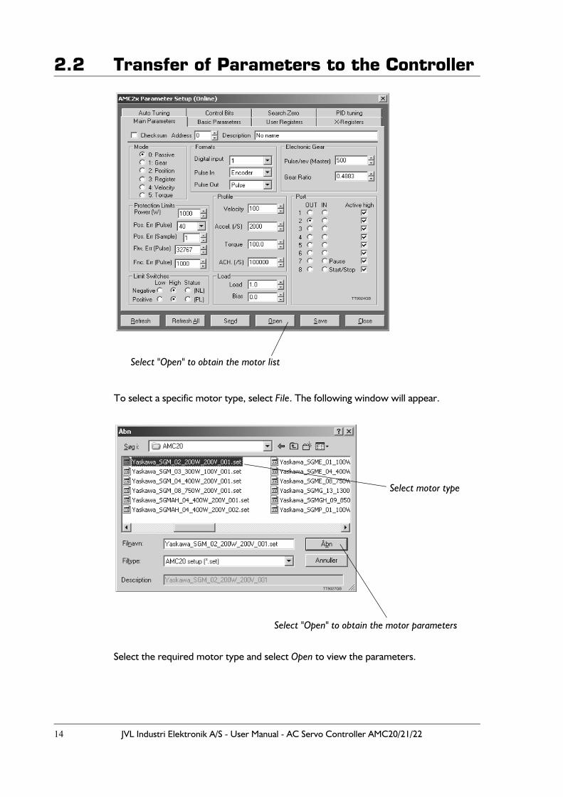
To select a specific motor type, select File. The following window will appear.
Select the required motor type and select Open to view the parameters.
Select "Open" to obtain the motor list
TT9024GB
Select "Open" to obtain the motor parameters
Select motor type
TT9027GB
JVL Industri Elektronik A/S - User Manual - AC Servo Controller AMC20/21/22 15
2.2 Transfer of Parameters to the Controller
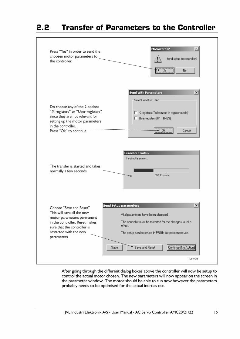
After going through the different dialog boxes above the controller will now be setup to control the actual motor chosen. The new parameters will now appear on the screen in the parameter window. The motor should be able to run now however the parameters probably needs to be optimised for the actual inertias etc.
Select "Open" to get the motor parameters
TT0587GB
Choose “Save and Reset”This will save all the newmotor parameters permanentin the controller. Reset makessure that the controller is restarted with the newparameters
Do choose any of the 2 options“X-registers” or “User-registers”since they are not relevant for setting up the motor parametersin the controller.Press “Ok” to continue.
The transfer is started and takesnormally a few seconds.
Press “Yes” in order to send the choosen motor parameters tothe controller.
16 JVL Industri Elektronik A/S - User Manual - AC Servo Controller AMC20/21/22
2.3 Current filter optimizing
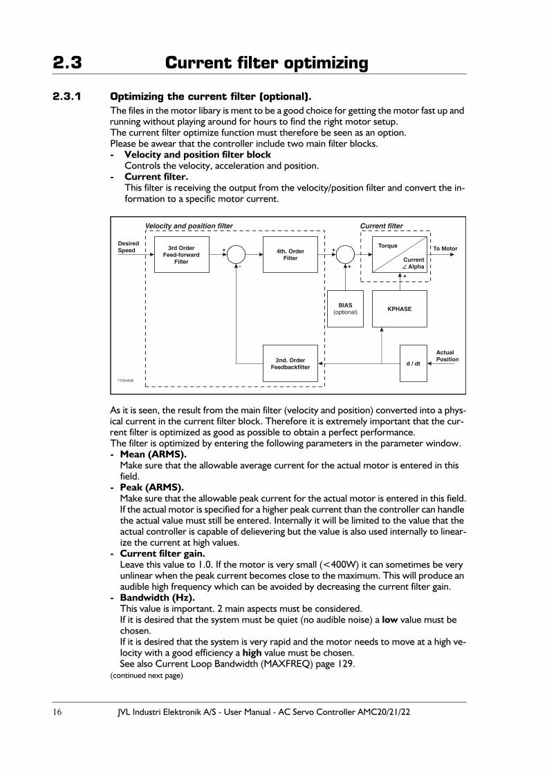
2.3.1 Optimizing the current filter (optional).The files in the motor libary is ment to be a good choice for getting the motor fast up and running without playing around for hours to find the right motor setup.The current filter optimize function must therefore be seen as an option.Please be awear that the controller include two main filter blocks.- Velocity and position filter block
Controls the velocity, acceleration and position.- Current filter.
This filter is receiving the output from the velocity/position filter and convert the in-formation to a specific motor current.
As it is seen, the result from the main filter (velocity and position) converted into a phys-ical current in the current filter block. Therefore it is extremely important that the cur-rent filter is optimized as good as possible to obtain a perfect performance. The filter is optimized by entering the following parameters in the parameter window.- Mean (ARMS).
Make sure that the allowable average current for the actual motor is entered in this field.
- Peak (ARMS).Make sure that the allowable peak current for the actual motor is entered in this field.If the actual motor is specified for a higher peak current than the controller can handle the actual value must still be entered. Internally it will be limited to the value that the actual controller is capable of delievering but the value is also used internally to linear-ize the current at high values.
- Current filter gain.Leave this value to 1.0. If the motor is very small (<400W) it can sometimes be very unlinear when the peak current becomes close to the maximum. This will produce an audible high frequency which can be avoided by decreasing the current filter gain.
- Bandwidth (Hz).This value is important. 2 main aspects must be considered. If it is desired that the system must be quiet (no audible noise) a low value must be chosen.If it is desired that the system is very rapid and the motor needs to move at a high ve-locity with a good efficiency a high value must be chosen.See also Current Loop Bandwidth (MAXFREQ) page 129.
(continued next page)
3rd OrderFeed-forward
Filter
4th. OrderFilter
2nd. OrderFeedbackfilter
BIAS(optional) KPHASE
d / dt
Torque
CurrentAlpha
DesiredSpeed + +
- +
+
ActualPosition
To Motor
TT0544GB
Current filterVelocity and position filter

JVL Industri Elektronik A/S - User Manual - AC Servo Controller AMC20/21/22 17
2.3 Current filter optimizing(continued from last page)
- PWM Freq. (KHz)Leave this value to 20 KHz. Only by using long motor cables or if the temperature of the controller starts to be critical it must be considered to chose 5 KHz.At 5 KHz the regulation is slower but the loses in the controller, the cable and in the motor is less. Normally it is not a problem to use 5KHz at motors with a rated power of 1kW and up since the internal timeconstant is anyway high.
When all the 5 parameters are setup start the optimize by selecting the "Optimize" but-ton. In advance be sure that the controller is in passive mode (MO=0). Now it will take a few seconds where the controller tests the actual motor connected to determine how the current filter must be calculated. Following progress bars will show.
When the progress bars dissapears the filter is optimized and ready to test.Remember to save the result permanent in the controller by typing MS (memory save) in the online editor.
Please notice that if the basic motor setup is NOT done on basis of a motor parameter file from the motor libary it is important to tune the mainfilter (velocity/position filter).Follow the next couple of pages to do this.
Enter the motors allowableaverage current in this field.
Enter the motors allowablepeak current in this field.
Leave this field at 1.0 (default).
Bandwidth for the current filtercan be specified here. Normally1000Hz will do.
The motor output carrier frequenceis specified here (default = 20KHz).
Use “Optimize” after setting theparameters above to prober values.
TT0588GB
TT0589GB
18 JVL Industri Elektronik A/S - User Manual - AC Servo Controller AMC20/21/22
2.4 Adjustment of Servo Regulation
2.4.1 Selection of Tuning MethodBefore tuning is carried out, it should be noted that 2 different methods of tuning are available:
1. Manual tuning using a PID filterFor simple and non-critical applications, the PID filter (1st. order filter) can be select-ed. The PID can only be manually adjusted. PID tuning involves 4 parameters: KP, KI, KD and KF (feed forward).Advantages:It is easy to obtain a stable system, also in cases where the transmission is elastic.Tuning can be done while the motor remains in a stationary position.Disadvantages:Dynamic performance is not as good as that obtained with auto-tuning.Coarse adjustment of the filter is done quickly, but it takes some time and know-how to optimise the filter for best performance.
2. Auto-tuning using 2nd. to 6th. order filter.Auto-tuning provides a method of tuning that is much better than manual tuning.This tuning involves a library of special "recipes" that are optimised for different ap-plications and motor types.Advantages:It is easy to obtain an extremely good filter setting.Dynamic performance is optimal.The higher filter order makes it possible to avoid oscillations caused by non-linear mechanics.Very fast settling times can be obtained.Recipes can be made for OEM users who require specific system performance in an application.Disadvantages:The motor will move during the tuning sequence while the Controller determines the system performance. In case of extremely elastic or "sloppy" mechanics, it can be difficult to get a valid tun-ing result.
Choosing the right method of tuning: Normally auto-tuning is recommended but in cases where the mechanics of a system are very elastic or the allowable positioning range of the motor is limited, manual PID tuning is recommended.
JVL Industri Elektronik A/S - User Manual - AC Servo Controller AMC20/21/22 19
2.4 Adjustment of Servo Regulation
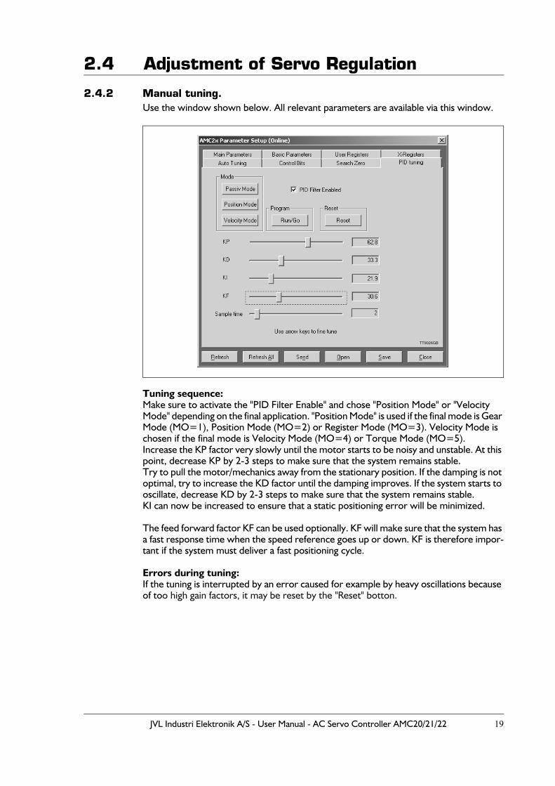
2.4.2 Manual tuning.Use the window shown below. All relevant parameters are available via this window.
Tuning sequence:Make sure to activate the "PID Filter Enable" and chose "Position Mode" or "Velocity Mode" depending on the final application. "Position Mode" is used if the final mode is Gear Mode (MO=1), Position Mode (MO=2) or Register Mode (MO=3). Velocity Mode is chosen if the final mode is Velocity Mode (MO=4) or Torque Mode (MO=5). Increase the KP factor very slowly until the motor starts to be noisy and unstable. At this point, decrease KP by 2-3 steps to make sure that the system remains stable.Try to pull the motor/mechanics away from the stationary position. If the damping is not optimal, try to increase the KD factor until the damping improves. If the system starts to oscillate, decrease KD by 2-3 steps to make sure that the system remains stable.KI can now be increased to ensure that a static positioning error will be minimized.
The feed forward factor KF can be used optionally. KF will make sure that the system has a fast response time when the speed reference goes up or down. KF is therefore impor-tant if the system must deliver a fast positioning cycle.
Errors during tuning:If the tuning is interrupted by an error caused for example by heavy oscillations because of too high gain factors, it may be reset by the "Reset" botton.
TT9026GB
20 JVL Industri Elektronik A/S - User Manual - AC Servo Controller AMC20/21/22
2.4 Adjustment of Servo Regulation
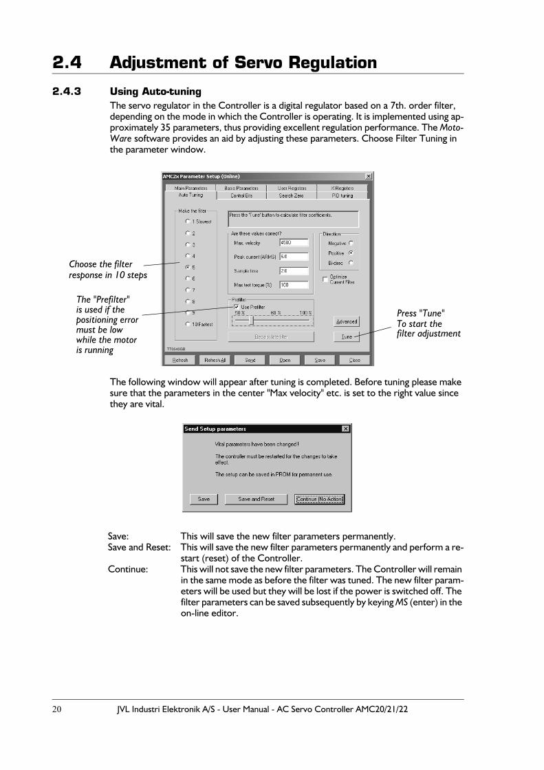
2.4.3 Using Auto-tuningThe servo regulator in the Controller is a digital regulator based on a 7th. order filter, depending on the mode in which the Controller is operating. It is implemented using ap-proximately 35 parameters, thus providing excellent regulation performance. The Moto-Ware software provides an aid by adjusting these parameters. Choose Filter Tuning in the parameter window.
The following window will appear after tuning is completed. Before tuning please make sure that the parameters in the center "Max velocity" etc. is set to the right value since they are vital.
Save: This will save the new filter parameters permanently.Save and Reset: This will save the new filter parameters permanently and perform a re-
start (reset) of the Controller.Continue: This will not save the new filter parameters. The Controller will remain
in the same mode as before the filter was tuned. The new filter param-eters will be used but they will be lost if the power is switched off. The filter parameters can be saved subsequently by keying MS (enter) in the on-line editor.
TT0540GB
Press "Tune"To start the filter adjustment
Choose the filterresponse in 10 steps
The "Prefilter"is used if thepositioning errormust be lowwhile the motoris running
JVL Industri Elektronik A/S - User Manual - AC Servo Controller AMC20/21/22 21
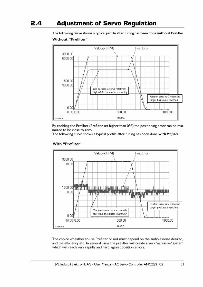
2.4 Adjustment of Servo RegulationThe following curve shows a typical profile after tuning has been done without Prefilter.
By enabling the Prefilter (Prefilter set higher than 0%) the positioning error can be min-imized to be close to zero. The following curve shows a typical profile after tuning has been done with Prefilter.
The choice wheather to use Prefilter or not must depend on the audible noise desired, and the efficiency etc. In general using the prefilter will create a very "agressive" system which will reach very rapidly and hard against position errors.
TT0541GB
Position error is 0 when thetarget position is reached.
The position error is relativelyhigh while the motor is running
Without “Prefilter”
TT0564GB
Position error is 0 when thetarget position is reached.
The position error is extremelylow while the motor is running
With “Prefilter”
22 JVL Industri Elektronik A/S - User Manual - AC Servo Controller AMC20/21/22
2.5 Adjustment of BIAS
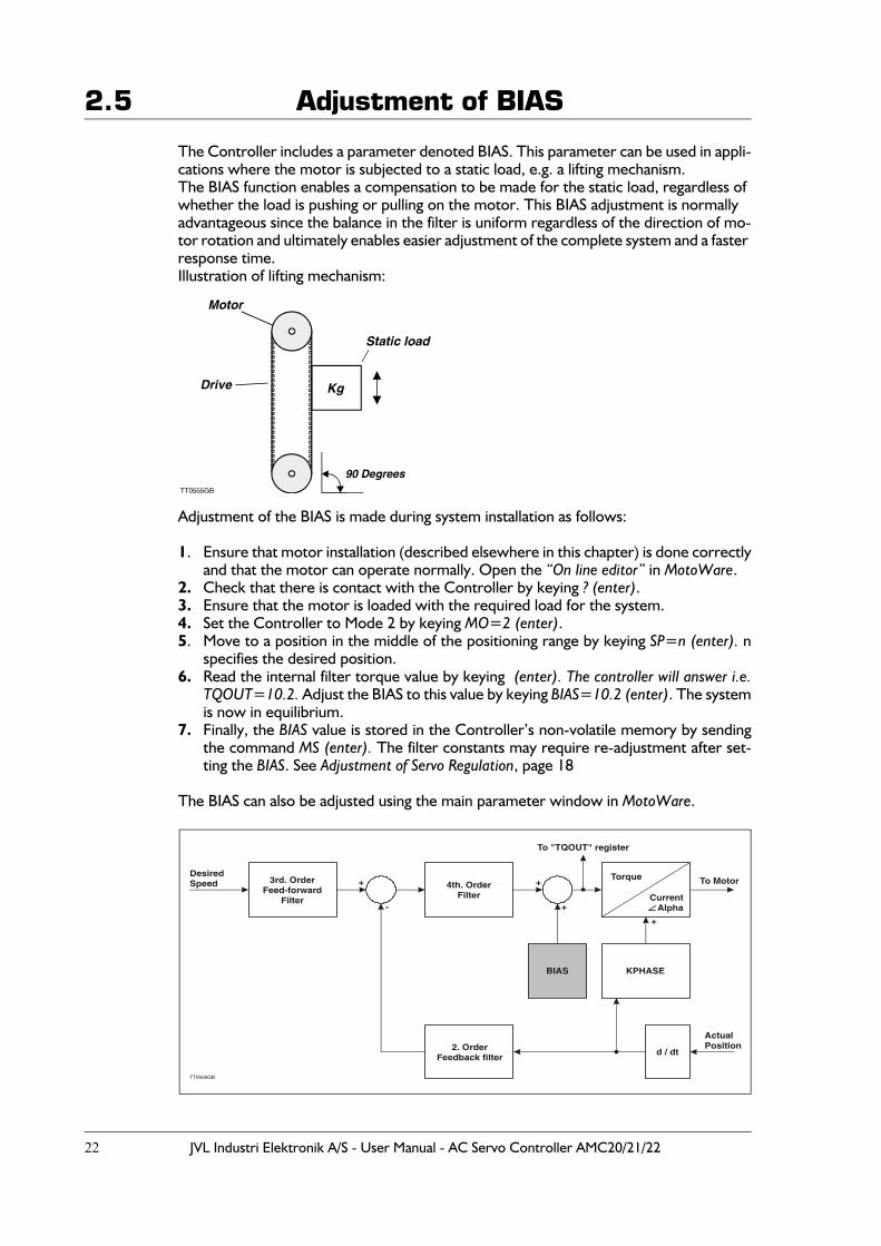
The Controller includes a parameter denoted BIAS. This parameter can be used in appli-cations where the motor is subjected to a static load, e.g. a lifting mechanism.The BIAS function enables a compensation to be made for the static load, regardless of whether the load is pushing or pulling on the motor. This BIAS adjustment is normally advantageous since the balance in the filter is uniform regardless of the direction of mo-tor rotation and ultimately enables easier adjustment of the complete system and a faster response time.Illustration of lifting mechanism:
Adjustment of the BIAS is made during system installation as follows:
1. Ensure that motor installation (described elsewhere in this chapter) is done correctlyand that the motor can operate normally. Open the “On line editor” in MotoWare.
2. Check that there is contact with the Controller by keying ? (enter).3. Ensure that the motor is loaded with the required load for the system.4. Set the Controller to Mode 2 by keying MO=2 (enter).5. Move to a position in the middle of the positioning range by keying SP=n (enter). n
specifies the desired position. 6. Read the internal filter torque value by keying (enter). The controller will answer i.e.
TQOUT=10.2. Adjust the BIAS to this value by keying BIAS=10.2 (enter). The systemis now in equilibrium.
7. Finally, the BIAS value is stored in the Controller’s non-volatile memory by sendingthe command MS (enter). The filter constants may require re-adjustment after set-ting the BIAS. See Adjustment of Servo Regulation, page 18
The BIAS can also be adjusted using the main parameter window in MotoWare.
3rd. OrderFeed-forward
Filter
4th. OrderFilter
2. OrderFeedback filter
KPHASE
d / dt
Torque
To "TQOUT" register
CurrentAlpha
DesiredSpeed + +
- +
+
ActualPosition
To Motor
TT0556GB
BIAS

JVL Industri Elektronik A/S - User Manual - AC Servo Controller AMC20/21/22 23
3 Hardware
24 JVL Industri Elektronik A/S - User Manual - AC Servo Controller AMC20/21/22
3.1 Connections
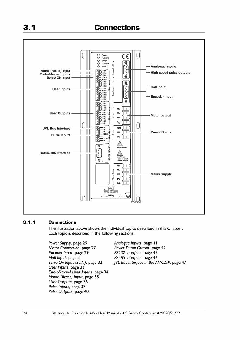
3.1.1 ConnectionsThe illustration above shows the individual topics described in this Chapter.Each topic is described in the following sections:
Power Supply, page 25 Analogue Inputs, page 41Motor Connection, page 27 Power Dump Output, page 42Encoder Input, page 29 RS232 Interface, page 43Hall Input, page 31 RS485 Interface, page 46Servo On Input (SON), page 32 JVL-Bus Interface in the AMC2xP, page 47User Inputs, page 33End-of-travel Limit Inputs, page 34Home (Reset) Input, page 35User Outputs, page 36Pulse Inputs, page 37Pulse Outputs, page 40
!
Analogue inputs
High speed pulse outputs
Hall Input
Encoder Input
Motor output
Power Dump
Mains Supply
RS232/485 Interface
Pulse Inputs
JVL-Bus Interface
User Outputs
User Inputs
End-of-travel inputsServo ON input
Home (Reset) input
TT0504GB
JVL Industri Elektronik A/S - User Manual - AC Servo Controller AMC20/21/22 25
3.2 Power Supply
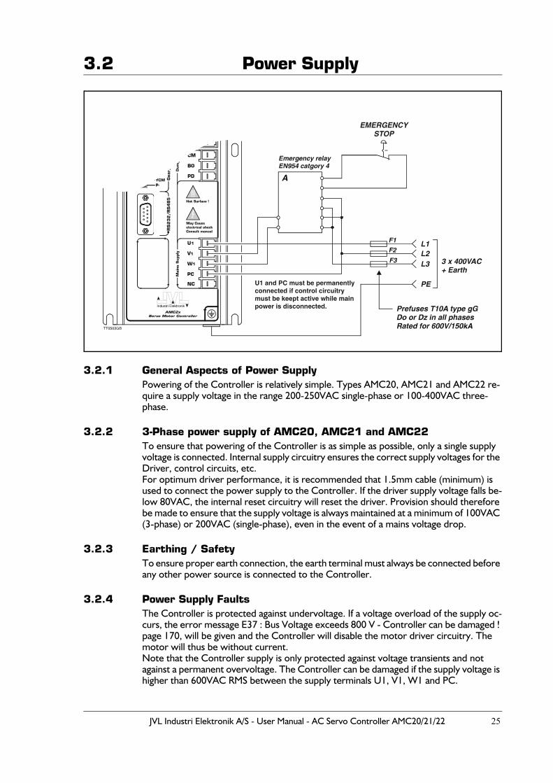
3.2.1 General Aspects of Power SupplyPowering of the Controller is relatively simple. Types AMC20, AMC21 and AMC22 re-quire a supply voltage in the range 200-250VAC single-phase or 100-400VAC three-phase.
3.2.2 3-Phase power supply of AMC20, AMC21 and AMC22
To ensure that powering of the Controller is as simple as possible, only a single supply voltage is connected. Internal supply circuitry ensures the correct supply voltages for the Driver, control circuits, etc. For optimum driver performance, it is recommended that 1.5mm cable (minimum) is used to connect the power supply to the Controller. If the driver supply voltage falls be-low 80VAC, the internal reset circuitry will reset the driver. Provision should therefore be made to ensure that the supply voltage is always maintained at a minimum of 100VAC (3-phase) or 200VAC (single-phase), even in the event of a mains voltage drop.
3.2.3 Earthing / SafetyTo ensure proper earth connection, the earth terminal must always be connected before any other power source is connected to the Controller.
3.2.4 Power Supply FaultsThe Controller is protected against undervoltage. If a voltage overload of the supply oc-curs, the error message E37 : Bus Voltage exceeds 800 V - Controller can be damaged ! page 170, will be given and the Controller will disable the motor driver circuitry. The motor will thus be without current.Note that the Controller supply is only protected against voltage transients and not against a permanent overvoltage. The Controller can be damaged if the supply voltage is higher than 600VAC RMS between the supply terminals U1, V1, W1 and PC.
U1 and PC must be permanentlyconnected if control circuitrymust be keept active while mainpower is disconnected.
EMERGENCYSTOP
26 JVL Industri Elektronik A/S - User Manual - AC Servo Controller AMC20/21/22
3.2 Power Supply
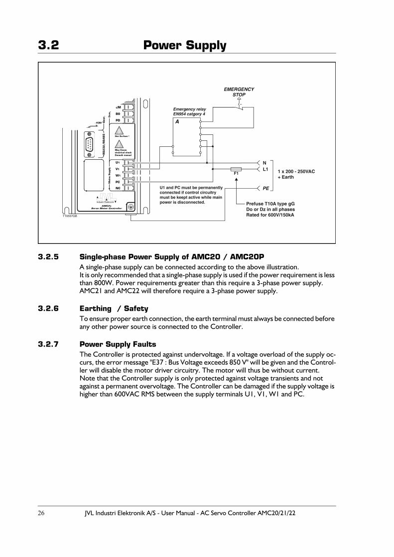
3.2.5 Single-phase Power Supply of AMC20 / AMC20PA single-phase supply can be connected according to the above illustration.It is only recommended that a single-phase supply is used if the power requirement is less than 800W. Power requirements greater than this require a 3-phase power supply.AMC21 and AMC22 will therefore require a 3-phase power supply.
3.2.6 Earthing / SafetyTo ensure proper earth connection, the earth terminal must always be connected before any other power source is connected to the Controller.
3.2.7 Power Supply FaultsThe Controller is protected against undervoltage. If a voltage overload of the supply oc-curs, the error message "E37 : Bus Voltage exceeds 850 V" will be given and the Control-ler will disable the motor driver circuitry. The motor will thus be without current.Note that the Controller supply is only protected against voltage transients and not against a permanent overvoltage. The Controller can be damaged if the supply voltage is higher than 600VAC RMS between the supply terminals U1, V1, W1 and PC.
U1 and PC must be permanentlyconnected if control circuitrymust be keept active while mainpower is disconnected.
N
F1L1 1 x 200 - 250VAC
+ Earth
Prefuse T10A type gGDo or Dz in all phasesRated for 600V/150kATT0557GB
JVL Industri Elektronik A/S - User Manual - AC Servo Controller AMC20/21/22 27
3.3 Motor Connection3.3.1 General Aspects of Motor Connection
The Controller is designed for use with common AC servo motors (brushless) with an incremental encoder. The Controller can supply high continuous and peak currents. These current values must be set using the software commands CA and CP.The Controller Driver uses IGBT transistors, which give exceptionally good perform-ance. The motor voltage is regulated at a frequency of 20kHz, which ensures that the motor does not produce any audible noise as a result of regulation.The Driver’s switching time is very short (<400nS), which can result in high-frequency noise components in the cables between the Driver and the motor. In certain situations this can result in undesirable influences on other electronic equip-ment in close proximity to the servo motor system. To avoid this problem, the connec-tion between the Controller and the motor should be made using screened cable, as shown in the illustrations on page 28. Furthermore, it is strongly recommended that screened cable is also used for the encoder cable to avoid any influence from the motor cable affecting the encoder signal.
3.3.2 Short-circuiting of the Motor OutputThe Motor Output can withstand short-circuiting between the U2, V2, W2 terminals.In addition, all motor terminals can withstand short-circuiting to ground or to the positive supply. If a short circuit occurs, the Controller will stop all activity and report an error condition by activating the red Current LED. In addition, the Controller’s error register will be ac-tivated. See the ES and EST commands.
3.3.3 Allowable Motor InductanceThe Driver can drive motors that have an inductance per phase in the range 1 to 20 mH. Please note that the mains voltage also has an influence.If a motor with a lower inductance is used, an inductance of 0.5-1mH must be connected in series with each motor lead. This inductance will function as an integrator and ensure that the Controller controls the current correctly.
3.3.4 Allowable cable lengthSince a typical motor cable have a capacitance of 0.22nF per meter the total cable length can not be infinitive since the switching losses in the cable as well as in the controller will be extreme.As a general rule the following maximum lengths are recommended :
At 5kHz:The capacitive load of the output of the controller may not exceed 12nF(18nF). This val-ue is normally exceeded having more than 20m(30m) cable.
At 20kHz (default):The capacitive load of the output of the controller may not exceed 3nF(4.5nF). This value includes the internal capacitance of the motor.This value is normally exceeded having more than 5m(7.5m) cable.
The values in brackets () is valid if 230VAC is used as supply.
The controlbit CB2 determines the switching frequency. See also CB2 - Set low PWM output frequency page 92.If a higher cable length is desired please insert a motor inductor between the controller and the cable.
28 JVL Industri Elektronik A/S - User Manual - AC Servo Controller AMC20/21/22
3.3 Motor Connection
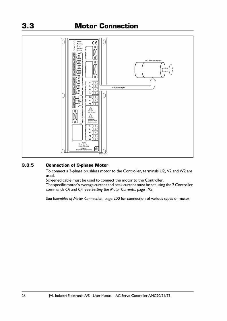
3.3.5 Connection of 3-phase MotorTo connect a 3-phase brushless motor to the Controller, terminals U2, V2 and W2 are used. Screened cable must be used to connect the motor to the Controller. The specific motor’s average current and peak current must be set using the 2 Controller commands CA and CP. See Setting the Motor Currents, page 195.
See Examples of Motor Connection, page 200 for connection of various types of motor.
!
TT0563GB
AC Servo Motor
Motor Output
JVL Industri Elektronik A/S - User Manual - AC Servo Controller AMC20/21/22 29
3.4 Encoder Input
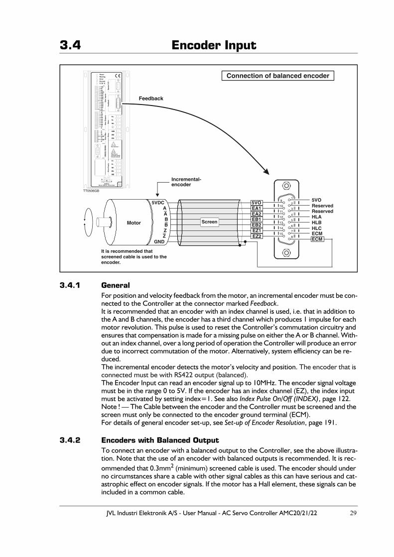
3.4.1 GeneralFor position and velocity feedback from the motor, an incremental encoder must be con-nected to the Controller at the connector marked Feedback.It is recommended that an encoder with an index channel is used, i.e. that in addition to the A and B channels, the encoder has a third channel which produces 1 impulse for each motor revolution. This pulse is used to reset the Controller’s commutation circuitry and ensures that compensation is made for a missing pulse on either the A or B channel. With-out an index channel, over a long period of operation the Controller will produce an error due to incorrect commutation of the motor. Alternatively, system efficiency can be re-duced.The incremental encoder detects the motor’s velocity and position. The encoder that is connected must be with RS422 output (balanced).The Encoder Input can read an encoder signal up to 10MHz. The encoder signal voltage must be in the range 0 to 5V. If the encoder has an index channel (EZ), the index input must be activated by setting index=1. See also Index Pulse On/Off (INDEX), page 122. Note ! — The Cable between the encoder and the Controller must be screened and the screen must only be connected to the encoder ground terminal (ECM).For details of general encoder set-up, see Set-up of Encoder Resolution, page 191.
3.4.2 Encoders with Balanced OutputTo connect an encoder with a balanced output to the Controller, see the above illustra-tion. Note that the use of an encoder with balanced outputs is recommended. It is rec-ommended that 0.3mm2 (minimum) screened cable is used. The encoder should under no circumstances share a cable with other signal cables as this can have serious and cat-astrophic effect on encoder signals. If the motor has a Hall element, these signals can be included in a common cable.
!
Connection of balanced encoder
5VO
ECMECM
HLA
ReservedReserved
HLBHLC
5VOEA1EA2EB1EB2EZ1EZ2
1
2
3
4
5
6
7
8
9
10
11
12
13
14
15
It is recommended that screened cable is used to theencoder.
Motor
Incremental-encoder
5VDC
B
A
B
A
ZZ
GND
Screen
TT0506GB
Feedback
30 JVL Industri Elektronik A/S - User Manual - AC Servo Controller AMC20/21/22
3.4 Encoder Input
3.4.3 Special Encoders/SensorsJVL currently plans to supply other adaptor modules for other types of encoder and sen-sor. Contact JVL Industri Elektronik for further details.
Today following adaptor modules exists:
- Analogue feedback to encoder converter JVL type PA0094.This module will convert an analogue voltage (or current) into an encoder signal which can be connected directly to the AMC2x controller. Contact your local JVL representive to get more information.
- Resolver to Encoder converter JVL type PA0095.This module will convert a resolver signal into an encoder signal which can be con-nected directly to the AMC2x controller. Contact your local JVL representive to get more information.
3.4.4 Encoders with serial data transmission.The AMC2x also supports encoders with serial data communication in some extend. The two terminals at the "Feedback" connector is ment for this purpose.The two terminals are Pin 2 (ED1 = Data+) and Pin 3 (ED2 = Data-). This serial channel is made as a RS485 bidirectional interface. The protocol today supports the Yaskawa SG-MAH, SGMPH, SGMPH and SGMSH. See also the Encoder Type (ET), page 110 which shows how to setup the encoder input for different hardware formats/communication protocols. For connecting Yaskawa motors see Examples of Motor Connection, page 200.
Please contact JVL if other motors from other manufactors need to be connected.
JVL Industri Elektronik A/S - User Manual - AC Servo Controller AMC20/21/22 31
3.5 Hall Input
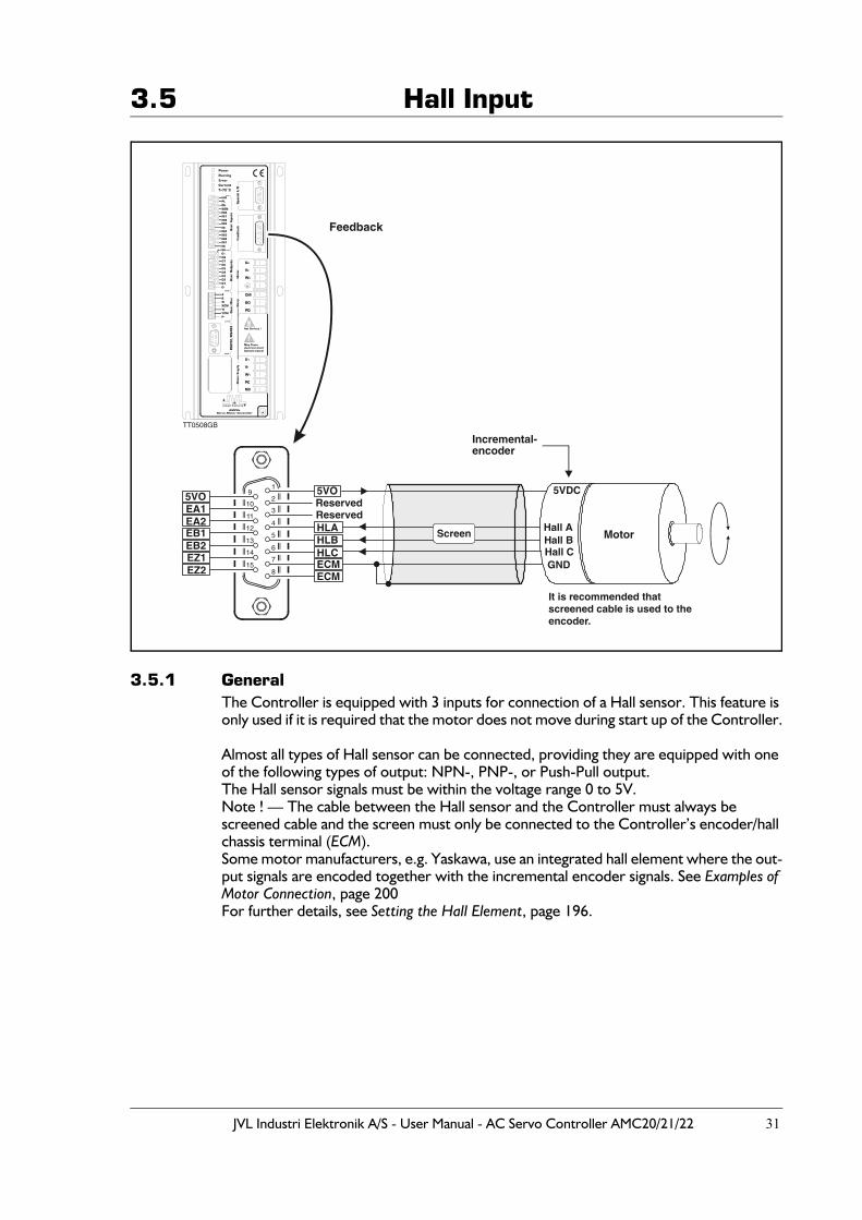
3.5.1 GeneralThe Controller is equipped with 3 inputs for connection of a Hall sensor. This feature is only used if it is required that the motor does not move during start up of the Controller.
Almost all types of Hall sensor can be connected, providing they are equipped with one of the following types of output: NPN-, PNP-, or Push-Pull output.The Hall sensor signals must be within the voltage range 0 to 5V.Note ! — The cable between the Hall sensor and the Controller must always be screened cable and the screen must only be connected to the Controller’s encoder/hall chassis terminal (ECM).Some motor manufacturers, e.g. Yaskawa, use an integrated hall element where the out-put signals are encoded together with the incremental encoder signals. See Examples of Motor Connection, page 200For further details, see Setting the Hall Element, page 196.
!
TT0508GB
Feedback
5VO
ECMECM
HLA
ReservedReserved
HLBHLC
5VOEA1EA2EB1EB2EZ1EZ2
1
2
3
4
5
6
7
8
9
10
11
12
13
14
15
It is recommended that screened cable is used to theencoder.
Motor
Incremental-encoder
5VDC
Hall AHall BHall CGND
Screen
32 JVL Industri Elektronik A/S - User Manual - AC Servo Controller AMC20/21/22
3.6 Servo On Input (SON)
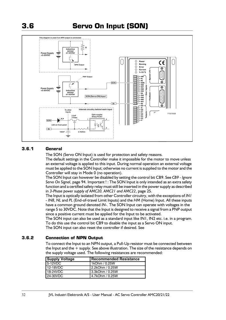
3.6.1 GeneralThe SON (Servo ON Input) is used for protection and safety reasons.The default settings in the Controller make it impossible for the motor to move unless an external voltage is applied to this input. During normal operation an external voltage must be applied to the SON Input; otherwise no current is supplied to the motor and the Controller will stay in Mode 0 (no operation).The SON Input can however be disabled by setting the control bit CB9. See CB9 - Ignore Servo On Signal, page 94. Important ! : The SON Input is only intended as an extra safety function and a certified safety relay must still be inserted in the power supply as described in 3-Phase power supply of AMC20, AMC21 and AMC22, page 25.The Input is optically isolated from other Controller circuitry, with the exceptions of IN1 - IN8, NL and PL (End-of-travel Limit Inputs) and the HM (Home) Input. All these inputs have a common ground denoted IN-. The SON Input can operate with voltages in the range 5 to 30VDC. Note that the Input is designed to receive a signal from a PNP output since a positive current must be applied for the Input to be activated.The SON input can also be used as a standard input like IN1, IN2 etc. i.e. in a program.To do this use the control bit CB9 to disable the input as a Servo ON input.The SON input can also reset the controller if desired. See
3.6.2 Connection of NPN OutputTo connect the Input to an NPN output, a Pull-Up resistor must be connected between the Input and the + supply. See above illustration. The size of the resistance depends on the supply voltage used. The following resistances are recommended: Supply Voltage Recommended Resistance5-12VDC 1kOhm / 0.25W12-18VDC 2.2kOhm / 0.25W18-24VDC 3.3kOhm / 0.25W24-30VDC 4.7kOhm / 0.25W
TT0578GB
SON (Servo ON) Input
SON
IN-
Power Supply+5-30VDC
Power Supply+5-30VDC
+
+
Inductivesensor
or similar
Inductivesensor
or similar
PNP Output
NPN Output
This diagram is used if an NPN output is connected
R
SON
IN-
To otherinputs
LED on front panel
100nF 2.7kOhm
Opto-couplerSharp PC357
3
1
2
4
2.2nFT-Filter
Internal circuitry behind each input
JVL Industri Elektronik A/S - User Manual - AC Servo Controller AMC20/21/22 33
3.7 User Inputs
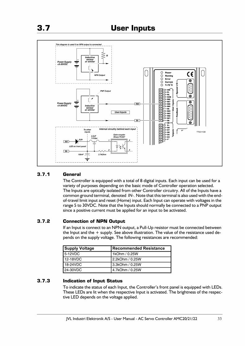
3.7.1 GeneralThe Controller is equipped with a total of 8 digital inputs. Each input can be used for a variety of purposes depending on the basic mode of Controller operation selected.The Inputs are optically isolated from other Controller circuitry. All of the Inputs have a common ground terminal, denoted IN-. Note that this terminal is also used with the end-of-travel limit input and reset (Home) input. Each Input can operate with voltages in the range 5 to 30VDC. Note that the Inputs should normally be connected to a PNP output since a positive current must be applied for an input to be activated.
3.7.2 Connection of NPN OutputIf an Input is connect to an NPN output, a Pull-Up resistor must be connected between the Input and the + supply. See above illustration. The value of the resistance used de-pends on the supply voltage. The following resistances are recommended:
3.7.3 Indication of Input StatusTo indicate the status of each Input, the Controller’s front panel is equipped with LEDs.These LEDs are lit when the respective Input is activated. The brightness of the respec-tive LED depends on the voltage applied.
Supply Voltage Recommended Resistance5-12VDC 1kOhm / 0.25W12-18VDC 2.2kOhm / 0.25W18-24VDC 3.3kOhm / 0.25W24-30VDC 4.7kOhm / 0.25W
34 JVL Industri Elektronik A/S - User Manual - AC Servo Controller AMC20/21/22
3.8 End-of-travel Limit Inputs
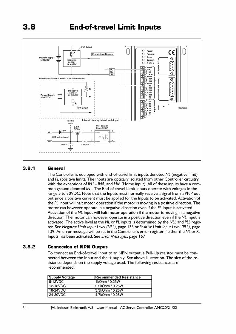
3.8.1 GeneralThe Controller is equipped with end-of-travel limit inputs denoted NL (negative limit) and PL (positive limit). The Inputs are optically isolated from other Controller circuitry with the exceptions of IN1 - IN8, and HM (Home input). All of these inputs have a com-mon ground denoted IN-. The End-of-travel Limit Inputs operate with voltages in the range 5 to 30VDC. Note that the Inputs must normally receive a signal from a PNP out-put since a positive current must be applied for the Inputs to be activated. Activation of the PL Input will halt motor operation if the motor is moving in a positive direction. The motor can however operate in a negative direction even if the PL Input is activated.Activation of the NL Input will halt motor operation if the motor is moving in a negative direction. The motor can however operate in a positive direction even if the NL Input is activated. The active level at the NL or PL inputs is determined by the NLL and PLL regis-ter. See Negative Limit Input Level (NLL), page 133 or Positive Limit Input Level (PLL), page 139. An error message will be set in the Controller’s error register if either the NL or PL Inputs has been activated. See Error Messages, page 167
3.8.2 Connection of NPN OutputTo connect an End-of-travel Input to an NPN output, a Pull-Up resistor must be con-nected between the Input and the + supply. See above illustration. The size of the re-sistance depends on the supply voltage used. The following resistances are recommended:
Supply Voltage Recommended Resistance5-12VDC 1kOhm / 0.25W12-18VDC 2.2kOhm / 0.25W18-24VDC 3.3kOhm / 0.25W24-30VDC 4.7kOhm / 0.25W
!
TT0512GB
End-of-travel inputs
NLPL
IN-
Power Supply+5-30VDC
+
Inductivesensor
or similar
PNP Output
Power Supply+5-30VDC
+Inductivesensor
or similar
NPN Output
This diagram is used if an NPN output is connected
R
NL1
IN-
To otherinputs
LED on front panel
100nF 2.7kOhm
Opto-couplerSharp PC357
3
1
2
4
2.2nFT-Filter
Internal circuitry behind each input
JVL Industri Elektronik A/S - User Manual - AC Servo Controller AMC20/21/22 35
3.9 Home (Reset) Input
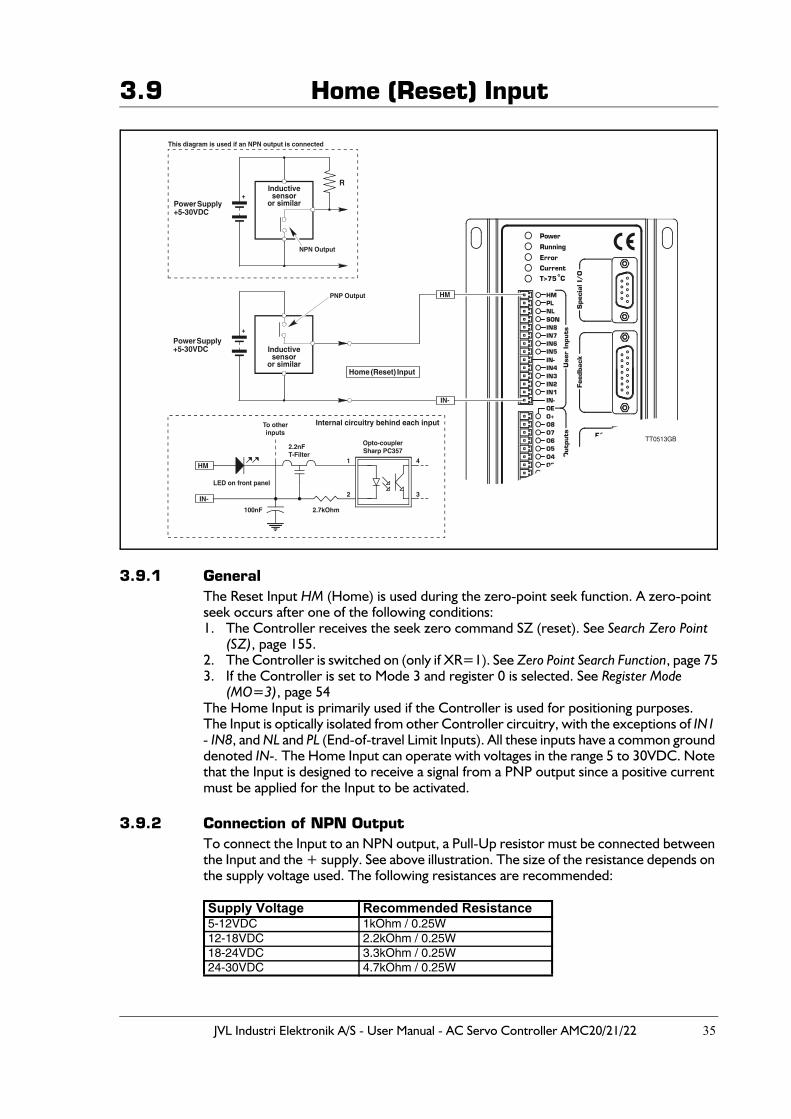
3.9.1 GeneralThe Reset Input HM (Home) is used during the zero-point seek function. A zero-point seek occurs after one of the following conditions:1. The Controller receives the seek zero command SZ (reset). See Search Zero Point
(SZ), page 155.2. The Controller is switched on (only if XR=1). See Zero Point Search Function, page 753. If the Controller is set to Mode 3 and register 0 is selected. See Register Mode
(MO=3), page 54The Home Input is primarily used if the Controller is used for positioning purposes.The Input is optically isolated from other Controller circuitry, with the exceptions of IN1 - IN8, and NL and PL (End-of-travel Limit Inputs). All these inputs have a common ground denoted IN-. The Home Input can operate with voltages in the range 5 to 30VDC. Note that the Input is designed to receive a signal from a PNP output since a positive current must be applied for the Input to be activated.
3.9.2 Connection of NPN OutputTo connect the Input to an NPN output, a Pull-Up resistor must be connected between the Input and the + supply. See above illustration. The size of the resistance depends on the supply voltage used. The following resistances are recommended: Supply Voltage Recommended Resistance5-12VDC 1kOhm / 0.25W12-18VDC 2.2kOhm / 0.25W18-24VDC 3.3kOhm / 0.25W24-30VDC 4.7kOhm / 0.25W
TT0513GB
Home (Reset) Input
HM
IN-
Power Supply+5-30VDC
Power Supply+5-30VDC
+
+
Inductivesensor
or similar
Inductivesensor
or similar
PNP Output
NPN Output
This diagram is used if an NPN output is connected
R
HM
IN-
To otherinputs
100nF 2.7kOhm
3
1
2
4
2.2nFT-Filter
Internal circuitry behind each input
LED on front panel
Opto-couplerSharp PC357
36 JVL Industri Elektronik A/S - User Manual - AC Servo Controller AMC20/21/22
3.10 User Outputs
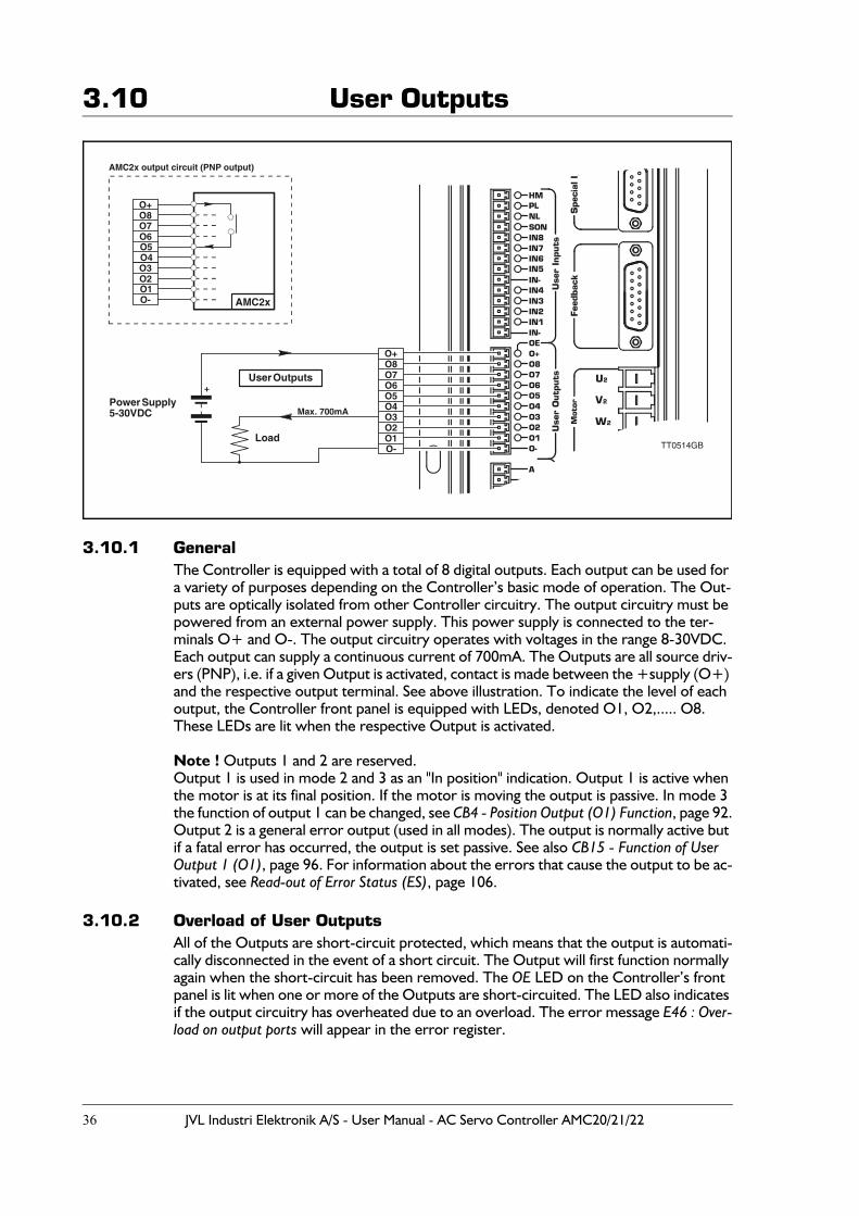
3.10.1 GeneralThe Controller is equipped with a total of 8 digital outputs. Each output can be used for a variety of purposes depending on the Controller’s basic mode of operation. The Out-puts are optically isolated from other Controller circuitry. The output circuitry must be powered from an external power supply. This power supply is connected to the ter-minals O+ and O-. The output circuitry operates with voltages in the range 8-30VDC. Each output can supply a continuous current of 700mA. The Outputs are all source driv-ers (PNP), i.e. if a given Output is activated, contact is made between the +supply (O+) and the respective output terminal. See above illustration. To indicate the level of each output, the Controller front panel is equipped with LEDs, denoted O1, O2,..... O8. These LEDs are lit when the respective Output is activated.
Note ! Outputs 1 and 2 are reserved.Output 1 is used in mode 2 and 3 as an "In position" indication. Output 1 is active when the motor is at its final position. If the motor is moving the output is passive. In mode 3 the function of output 1 can be changed, see CB4 - Position Output (O1) Function, page 92.Output 2 is a general error output (used in all modes). The output is normally active but if a fatal error has occurred, the output is set passive. See also CB15 - Function of User Output 1 (O1), page 96. For information about the errors that cause the output to be ac-tivated, see Read-out of Error Status (ES), page 106.
3.10.2 Overload of User OutputsAll of the Outputs are short-circuit protected, which means that the output is automati-cally disconnected in the event of a short circuit. The Output will first function normally again when the short-circuit has been removed. The OE LED on the Controller’s front panel is lit when one or more of the Outputs are short-circuited. The LED also indicates if the output circuitry has overheated due to an overload. The error message E46 : Over-load on output ports will appear in the error register.
TT0514GBO-O1
O3O2
O4
O8O7O6O5
O+
User Outputs
O4O5
O7O6
O8O+
Power Supply5-30VDC
+
O-O1
O3O2
AMC2x output circuit (PNP output)
Load
Max. 700mA
AMC2x
JVL Industri Elektronik A/S - User Manual - AC Servo Controller AMC20/21/22 37
3.11 Pulse Inputs
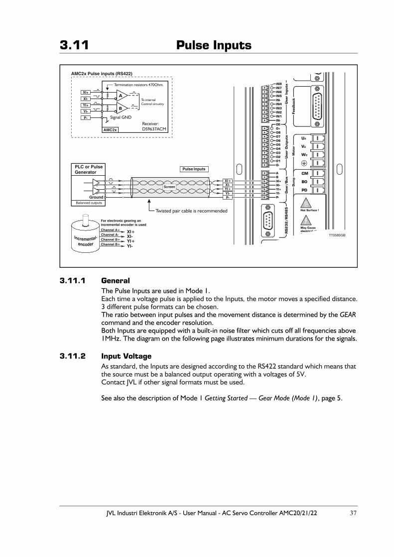
3.11.1 GeneralThe Pulse Inputs are used in Mode 1.Each time a voltage pulse is applied to the Inputs, the motor moves a specified distance.3 different pulse formats can be chosen.The ratio between input pulses and the movement distance is determined by the GEAR command and the encoder resolution.Both Inputs are equipped with a built-in noise filter which cuts off all frequencies above 1MHz. The diagram on the following page illustrates minimum durations for the signals.
3.11.2 Input VoltageAs standard, the Inputs are designed according to the RS422 standard which means that the source must be a balanced output operating with a voltages of 5V.Contact JVL if other signal formats must be used.
See also the description of Mode 1 Getting Started — Gear Mode (Mode 1), page 5.
!
XI-XI+
YI+YI-P-
Pulse Inputs
Channel A+ XI+XI-YI+YI-
For electronic gearing anincremental encoder is used
Channel A-Channel B+Channel B+
PLC or PulseGenerator
Balanced outputs
Ground
TT0585GB
Twisted pair cable is recommended
Termination resistors 470Ohm.
YI+
XI-
XI+
YI-
P-
AMC2x Pulse inputs (RS422)
AMC2x
Signal GND
To internalControl circuitry
A
B
Screen
Receiver:DS9637ACM
38 JVL Industri Elektronik A/S - User Manual - AC Servo Controller AMC20/21/22
3.11 Pulse Inputs
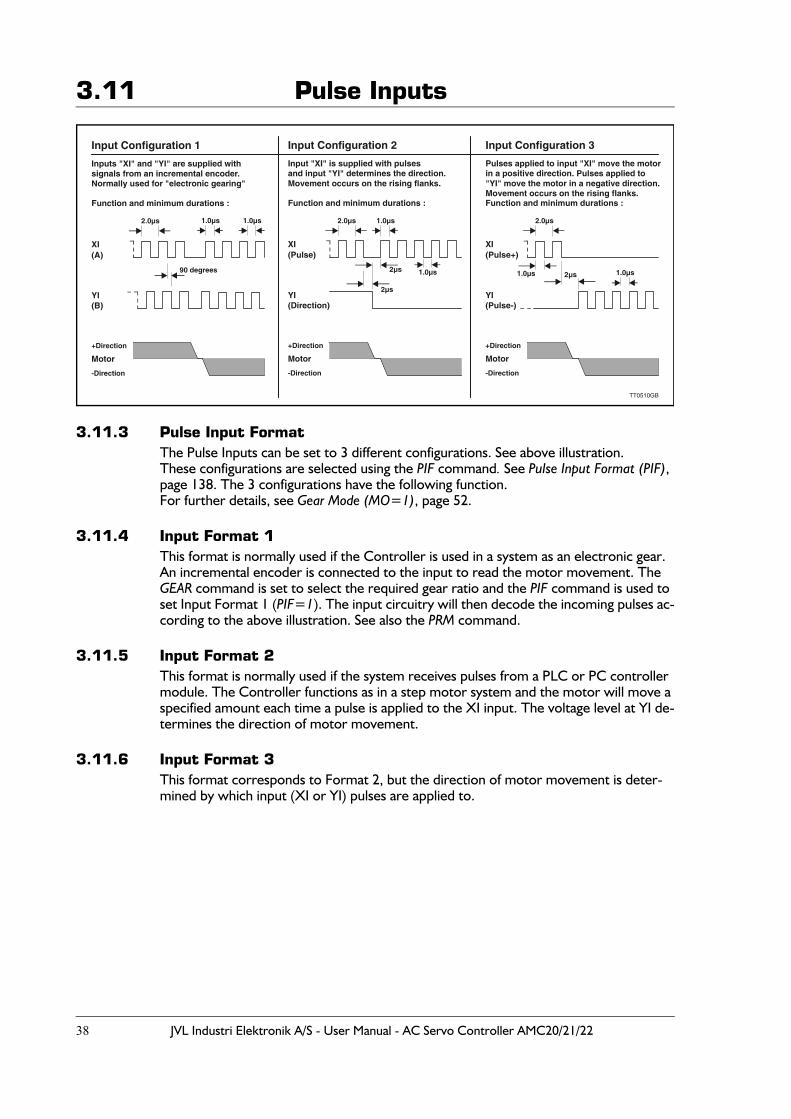
3.11.3 Pulse Input FormatThe Pulse Inputs can be set to 3 different configurations. See above illustration.These configurations are selected using the PIF command. See Pulse Input Format (PIF), page 138. The 3 configurations have the following function.For further details, see Gear Mode (MO=1), page 52.
3.11.4 Input Format 1This format is normally used if the Controller is used in a system as an electronic gear. An incremental encoder is connected to the input to read the motor movement. The GEAR command is set to select the required gear ratio and the PIF command is used to set Input Format 1 (PIF=1). The input circuitry will then decode the incoming pulses ac-cording to the above illustration. See also the PRM command.
3.11.5 Input Format 2This format is normally used if the system receives pulses from a PLC or PC controller module. The Controller functions as in a step motor system and the motor will move a specified amount each time a pulse is applied to the XI input. The voltage level at YI de-termines the direction of motor movement.
3.11.6 Input Format 3This format corresponds to Format 2, but the direction of motor movement is deter-mined by which input (XI or YI) pulses are applied to.
Function and minimum durations : Function and minimum durations : Function and minimum durations :
Inputs "XI" and "YI" are supplied withsignals from an incremental encoder.Normally used for "electronic gearing"
Input "XI" is supplied with pulsesand input "YI" determines the direction.Movement occurs on the rising flanks.
Pulses applied to input "XI" move the motorin a positive direction. Pulses applied to"YI" move the motor in a negative direction.Movement occurs on the rising flanks.
XI XI XI(A) (Pulse) (Pulse+)
(B) (Direction) (Pulse-)
Motor Motor Motor
+Direction +Direction +Direction
-Direction -Direction -Direction
YI YI YI
90 degrees
2µs
1.0µs
1.0µs 1.0µs 1.0µs
1.0µs 1.0µs2µs2µs
2.0µs 2.0µs 2.0µs
Input Configuration 1 Input Configuration 2 Input Configuration 3
TT0510GB
JVL Industri Elektronik A/S - User Manual - AC Servo Controller AMC20/21/22 39
3.11 Pulse Inputs
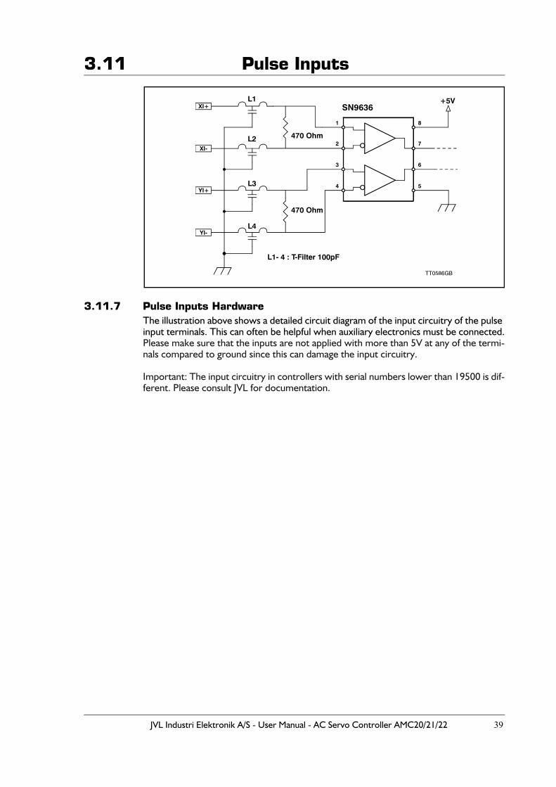
3.11.7 Pulse Inputs HardwareThe illustration above shows a detailed circuit diagram of the input circuitry of the pulse input terminals. This can often be helpful when auxiliary electronics must be connected.Please make sure that the inputs are not applied with more than 5V at any of the termi-nals compared to ground since this can damage the input circuitry.
Important: The input circuitry in controllers with serial numbers lower than 19500 is dif-ferent. Please consult JVL for documentation.
XI-
XI+
YI+
YI-
SN9636+5V
470 Ohm
470 Ohm
L1- 4 : T-Filter 100pF
TT0586GB
L4
L3
L1
L2
1 8
2 7
3 6
4 5
40 JVL Industri Elektronik A/S - User Manual - AC Servo Controller AMC20/21/22
3.12 Pulse Outputs
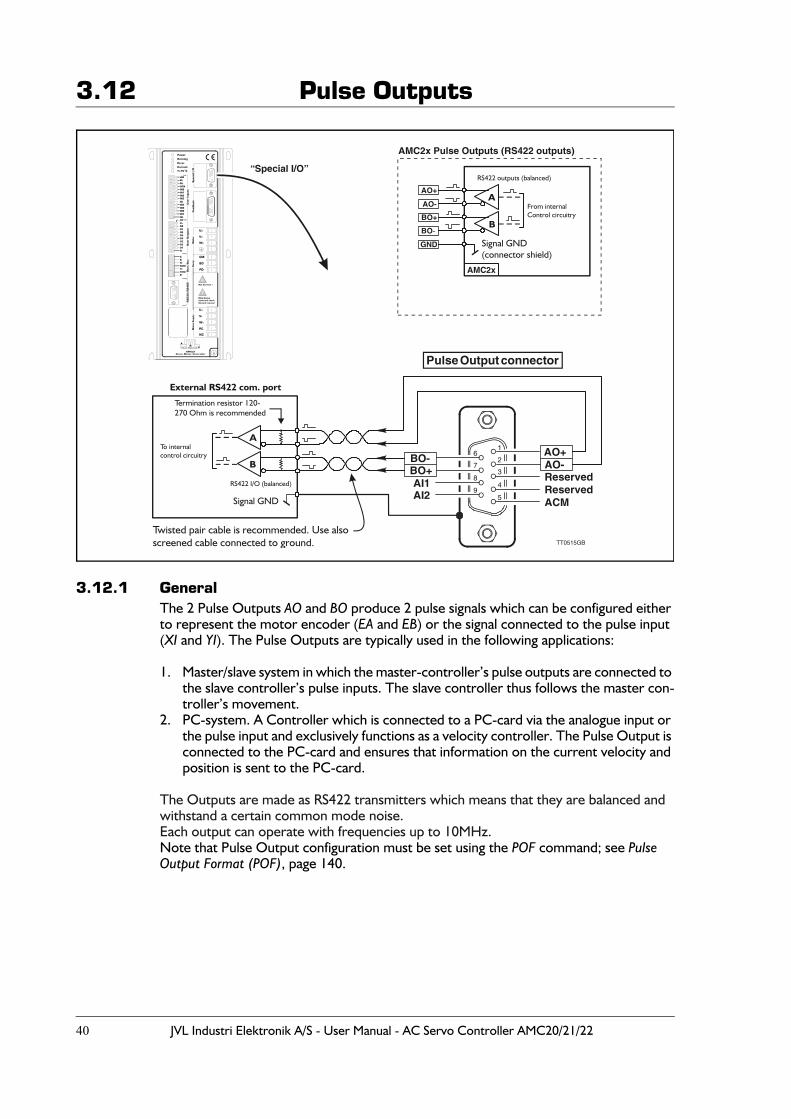
3.12.1 GeneralThe 2 Pulse Outputs AO and BO produce 2 pulse signals which can be configured either to represent the motor encoder (EA and EB) or the signal connected to the pulse input (XI and YI). The Pulse Outputs are typically used in the following applications:
1. Master/slave system in which the master-controller’s pulse outputs are connected to the slave controller’s pulse inputs. The slave controller thus follows the master con-troller’s movement.
2. PC-system. A Controller which is connected to a PC-card via the analogue input or the pulse input and exclusively functions as a velocity controller. The Pulse Output is connected to the PC-card and ensures that information on the current velocity and position is sent to the PC-card.
The Outputs are made as RS422 transmitters which means that they are balanced and withstand a certain common mode noise.Each output can operate with frequencies up to 10MHz.Note that Pulse Output configuration must be set using the POF command; see Pulse Output Format (POF), page 140.
!
TT0515GB
“Special I/O”
AO+
Reserved
AO-Reserved
ACM
BO-BO+AI1AI2
1
2
3
4
5
6
7
8
9
Pulse Output connector
BO+
AO-
AO+
BO-
GND
AMC2x Pulse Outputs (RS422 outputs)
AMC2x
A
Signal GND(connector shield)
B
From internalControl circuitry
RS422 outputs (balanced)
A
B
Signal GND
Twisted pair cable is recommended. Use alsoscreened cable connected to ground.
Termination resistor 120-270 Ohm is recommended
To internalcontrol circuitry
RS422 I/O (balanced)
External RS422 com. port
JVL Industri Elektronik A/S - User Manual - AC Servo Controller AMC20/21/22 41
3.13 Analogue Inputs
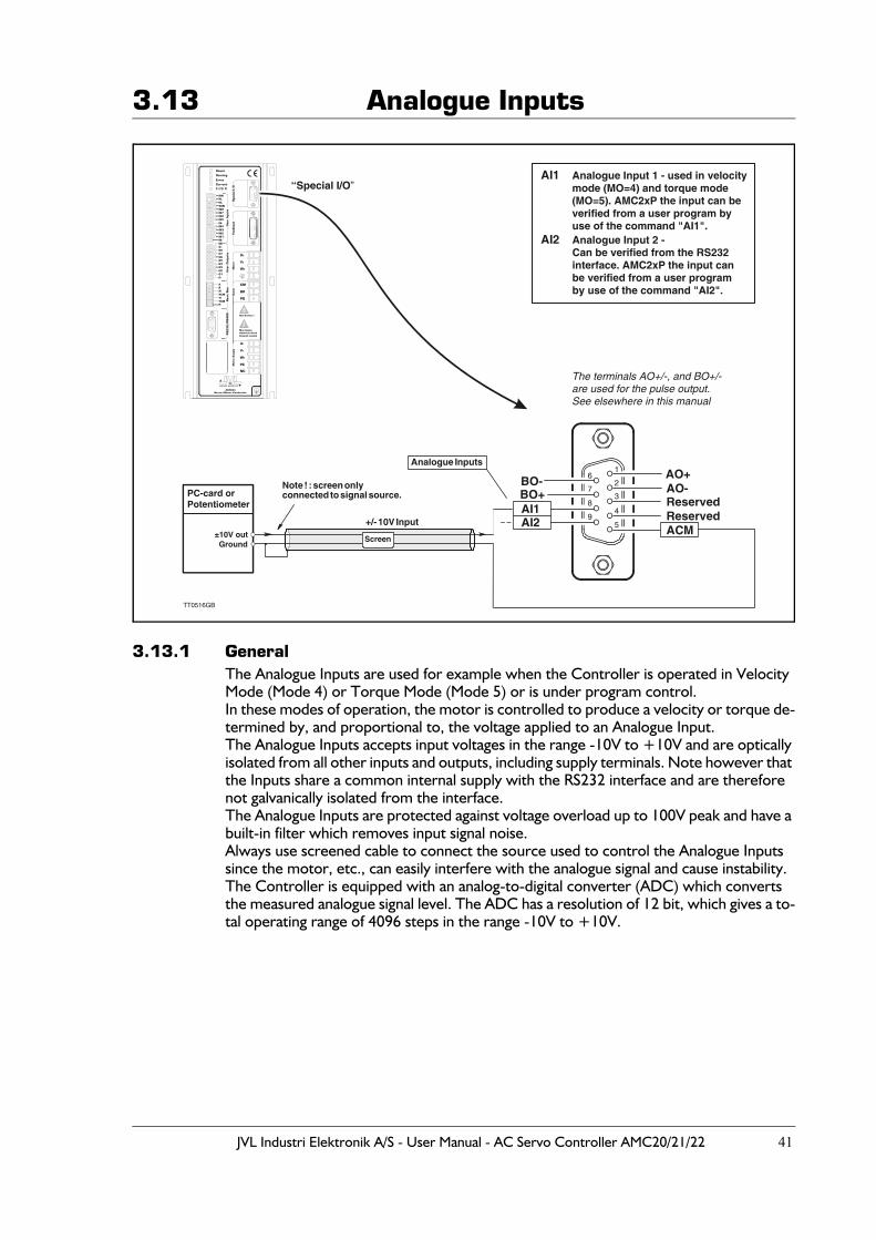
3.13.1 GeneralThe Analogue Inputs are used for example when the Controller is operated in Velocity Mode (Mode 4) or Torque Mode (Mode 5) or is under program control.In these modes of operation, the motor is controlled to produce a velocity or torque de-termined by, and proportional to, the voltage applied to an Analogue Input.The Analogue Inputs accepts input voltages in the range -10V to +10V and are optically isolated from all other inputs and outputs, including supply terminals. Note however that the Inputs share a common internal supply with the RS232 interface and are therefore not galvanically isolated from the interface.The Analogue Inputs are protected against voltage overload up to 100V peak and have a built-in filter which removes input signal noise.Always use screened cable to connect the source used to control the Analogue Inputs since the motor, etc., can easily interfere with the analogue signal and cause instability. The Controller is equipped with an analog-to-digital converter (ADC) which converts the measured analogue signal level. The ADC has a resolution of 12 bit, which gives a to-tal operating range of 4096 steps in the range -10V to +10V.
!
TT0516GB
“Special I/O”
AO+
Reserved
AO-Reserved
ACM
BO-
AI1
AI2
Analogue Input 1 - used in velocitymode (MO=4) and torque mode(MO=5). AMC2xP the input can beverified from a user program byuse of the command "AI1".Analogue Input 2 - Can be verified from the RS232interface. AMC2xP the input canbe verified from a user programby use of the command "AI2".
BO+AI1AI2
1
2
3
4
5
6
7
8
9
Analogue Inputs
+/- 10V Input
Note ! : screen onlyconnected to signal source.
±10V out
PC-card orPotentiometer
GroundScreen
The terminals AO+/-, and BO+/- are used for the pulse output.See elsewhere in this manual
42 JVL Industri Elektronik A/S - User Manual - AC Servo Controller AMC20/21/22
3.14 Power Dump Output
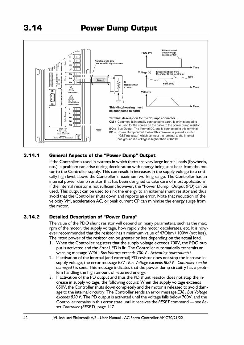
3.14.1 General Aspects of the “Power Dump” OutputIf the Controller is used in systems in which there are very large inertial loads (flywheels, etc.), a problem can arise during deceleration with energy being sent back from the mo-tor to the Controller supply. This can result in increases in the supply voltage to a criti-cally high level, above the Controller’s maximum working range. The Controller has an internal power dump resistor that has been designed to take care of most applications. If the internal resistor is not sufficient however, the “Power Dump” Output (PD) can be used. This output can be used to sink the energy to an external shunt resistor and thus avoid that the Controller shuts down and reports an error. Note that reduction of the velocity VM, acceleration AC, or peak current CP can minimise the energy surge from the motor.
3.14.2 Detailed Description of “Power Dump”The value of the PDO shunt resistor will depend on many parameters, such as the max. rpm of the motor, the supply voltage, how rapidly the motor decelerates, etc. It is how-ever recommended that the resistor has a minimum value of 47Ohm / 100W (not less). The rated power of the resistor can be greater or less depending on the actual load.1. When the Controller registers that the supply voltage exceeds 700V, the PDO out-
put is activated and the Error LED is lit. The Controller automatically transmits an warning message W36 : Bus Voltage exceeds 700 V - Activating powerdump !
2. If activation of the internal (and external) PD resistor does not stop the increase in supply voltage, the error message E37 : Bus Voltage exceeds 800 V - Controller can be damaged ! is sent. This message indicates that the power dump circuitry has a prob-lem handling the high amount of returned energy.
3. If activation of the PD output and thus the PD shunt resistor does not stop the in-crease in supply voltage, the following occurs: When the supply voltage exceeds 850V, the Controller shuts down completely and the motor is released to avoid dam-age to the internal circuitry. The Controller sends an error message E38 : Bus Voltage exceeds 850 V. The PD output is activated until the voltage falls below 700V, and the Controller remains in this error state until it receives the RESET command — see Re-set Controller (RESET), page 147.
!
TT0517GB
Velocity
Time
Time
Time
Voltage (V)
PDO (V)
RNot less than47 Ohm
Nom. 560V
700V
Energy fed back fromthe motor to the Controller
PDO activatedwhen voltageexceeds 700V
Shielding/housing mustbe connected to earth
Note ! : screen onlyconnected to signal source.
Screen
Common. Is internally connected to earth. Is only intended tobe used for the screen on the cable to the power dump resistor.Bus Output. The internal DC bus is connected to this terminal.Power Dump output. Behind this terminal is placed a switch(IGBT transistor) which connect the terminal to the internalbus ground if a voltage is higher than 700VDC.
Terminal description for the “Dump” connector.CM =
BO = PD =
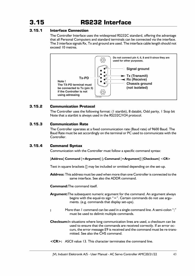
JVL Industri Elektronik A/S - User Manual - AC Servo Controller AMC20/21/22 43
3.15 RS232 Interface3.15.1 Interface Connection
The Controller Interface uses the widespread RS232C standard, offering the advantage that all Personal Computers and standard terminals can be connected via the interface. The 3 interface signals Rx, Tx and ground are used. The interface cable length should not exceed 10 metres.
3.15.2 Communication Protocol The Controller uses the following format: (1 startbit), 8 databit, Odd parity, 1 Stop bitNote that a startbit is always used in the RS232C/V24 protocol.
3.15.3 Communication RateThe Controller operates at a fixed communication rate (Baud rate) of 9600 Baud. The Baud Rate must be set accordingly on the terminal or PC used to communicate with the Controller.
3.15.4 Command SyntaxCommunication with the Controller must follow a specific command syntax:
[Address] Command [=Argument] [; Command [=Argument]] [Checksum] <CR>
Text in square brackets [] may be included or omitted depending on the set-up.
Address: This address must be used when more than one Controller is connected to the same interface. See also the ADDR command.
Command:The command itself.
Argument:The subsequent numeric argument for the command. An argument always begins with the equal-to sign “=”. Certain commands do not use argu-ments. (e.g. commands that display set-ups).
; More than 1 command can be used in a single command line. A semi-colon “;” must be used to delimit multiple commands.
Checksum:In situations where long communication lines are used, a checksum can be used to ensure that the commands are received correctly. If an error oc-curs, the error message E9 is received and the command must be re-trans-mitted. See also the CHS command.
<CR>: ASCII value 13. This character terminates the command line.
Tx-PD
Signal ground
Do not connect pin 4, 6, 8 and 9 since they areused for other purposes.
Chassis ground(not isolated)
Rx (Receive)Tx (Transmit)
5
37
2
1
TT0518GB
Note !The TX-PD terminal mustbe connected to Tx (pin 3) if the Controller is not using adressing
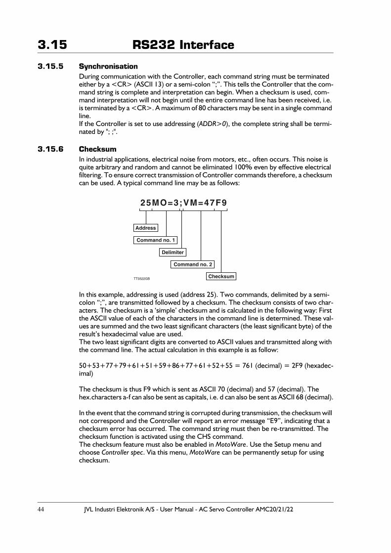
44 JVL Industri Elektronik A/S - User Manual - AC Servo Controller AMC20/21/22
3.15 RS232 Interface
3.15.5 SynchronisationDuring communication with the Controller, each command string must be terminated either by a <CR> (ASCII 13) or a semi-colon “;”. This tells the Controller that the com-mand string is complete and interpretation can begin. When a checksum is used, com-mand interpretation will not begin until the entire command line has been received, i.e. is terminated by a <CR>. A maximum of 80 characters may be sent in a single command line.If the Controller is set to use addressing (ADDR>0), the complete string shall be termi-nated by "; ;".
3.15.6 ChecksumIn industrial applications, electrical noise from motors, etc., often occurs. This noise is quite arbitrary and random and cannot be eliminated 100% even by effective electrical filtering. To ensure correct transmission of Controller commands therefore, a checksum can be used. A typical command line may be as follows:
In this example, addressing is used (address 25). Two commands, delimited by a semi-colon “;”, are transmitted followed by a checksum. The checksum consists of two char-acters. The checksum is a ‘simple’ checksum and is calculated in the following way: First the ASCII value of each of the characters in the command line is determined. These val-ues are summed and the two least significant characters (the least significant byte) of the result’s hexadecimal value are used.The two least significant digits are converted to ASCII values and transmitted along with the command line. The actual calculation in this example is as follow:
50+53+77+79+61+51+59+86+77+61+52+55 = 761 (decimal) = 2F9 (hexadec-imal)
The checksum is thus F9 which is sent as ASCII 70 (decimal) and 57 (decimal). The hex.characters a-f can also be sent as capitals, i.e. d can also be sent as ASCII 68 (decimal).
In the event that the command string is corrupted during transmission, the checksum will not correspond and the Controller will report an error message “E9”, indicating that a checksum error has occurred. The command string must then be re-transmitted. The checksum function is activated using the CHS command.The checksum feature must also be enabled in MotoWare. Use the Setup menu and choose Controller spec. Via this menu, MotoWare can be permanently setup for using checksum.
25MO=3;VM=47F9
Checksum
Address
Command no. 1
Command no. 2
Delimiter
TT0522GB
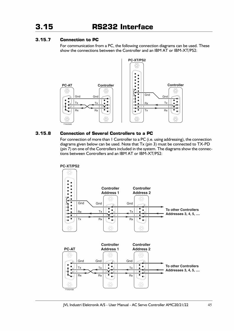
JVL Industri Elektronik A/S - User Manual - AC Servo Controller AMC20/21/22 45
3.15 RS232 Interface
3.15.7 Connection to PCFor communication from a PC, the following connection diagrams can be used. These show the connections between the Controller and an IBM AT or IBM-XT/PS2:
3.15.8 Connection of Several Controllers to a PCFor connection of more than 1 Controller to a PC (i.e. using addressing), the connection diagrams given below can be used. Note that Tx (pin 3) must be connected to TX-PD (pin 7) on one of the Controllers included in the system. The diagrams show the connec-tions between Controllers and an IBM AT or IBM-XT/PS2:
Controller
1
2
3
5
7
Gnd
PC-AT
Gnd
Rx
Tx
1
27
3
5
Tx
Rx
Controller
PC-XT/PS2
Gnd
Rx
Tx1
2
3
4
5
6
78
1
2
5
73
Gnd
Tx
Rx
TT0523GB
ControllerAddress 1
ControllerAddress 1
PC-AT
PC-XT/PS2
ControllerAddress 2
ControllerAddress 2
To other ControllersAddresses 3, 4, 5, ....
To other ControllersAddresses 3, 4, 5, ....
TT0524GB
Gnd Gnd Gnd
Gnd Gnd Gnd
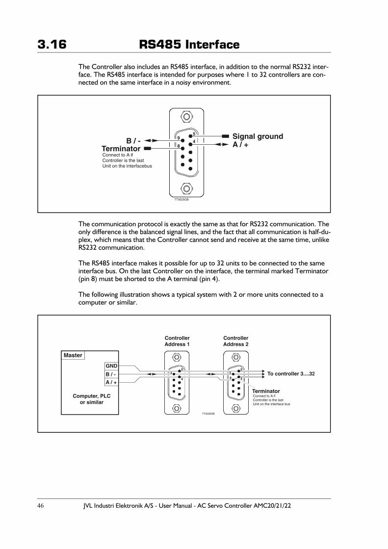
46 JVL Industri Elektronik A/S - User Manual - AC Servo Controller AMC20/21/22
3.16 RS485 Interface
The Controller also includes an RS485 interface, in addition to the normal RS232 inter-face. The RS485 interface is intended for purposes where 1 to 32 controllers are con-nected on the same interface in a noisy environment.
The communication protocol is exactly the same as that for RS232 communication. The only difference is the balanced signal lines, and the fact that all communication is half-du-plex, which means that the Controller cannot send and receive at the same time, unlike RS232 communication.
The RS485 interface makes it possible for up to 32 units to be connected to the same interface bus. On the last Controller on the interface, the terminal marked Terminator (pin 8) must be shorted to the A terminal (pin 4).
The following illustration shows a typical system with 2 or more units connected to a computer or similar.
Terminator
Signal groundA / + B / -
5
49
8
TT0525GB
Connect to A if Controller is the lastUnit on the interfacebus
Terminator
B / -
GND
A / +
5 5
4 4
9 9
8
TT0526GB
Connect to A if Controller is the lastUnit on the interface bus
Master
Computer, PLCor similar
Controller Address 1
Controller Address 2
To controller 3....32
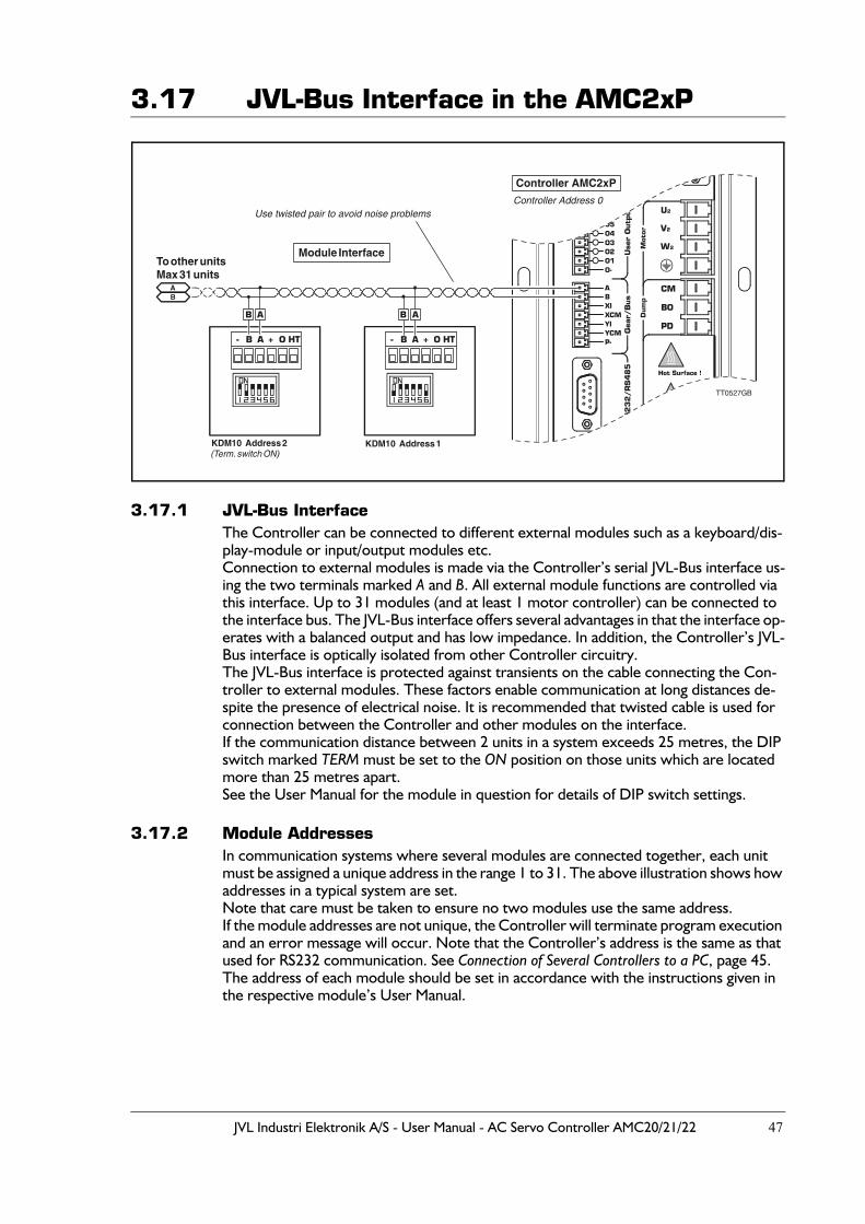
JVL Industri Elektronik A/S - User Manual - AC Servo Controller AMC20/21/22 47
3.17 JVL-Bus Interface in the AMC2xP
3.17.1 JVL-Bus InterfaceThe Controller can be connected to different external modules such as a keyboard/dis-play-module or input/output modules etc.Connection to external modules is made via the Controller’s serial JVL-Bus interface us-ing the two terminals marked A and B. All external module functions are controlled via this interface. Up to 31 modules (and at least 1 motor controller) can be connected to the interface bus. The JVL-Bus interface offers several advantages in that the interface op-erates with a balanced output and has low impedance. In addition, the Controller’s JVL-Bus interface is optically isolated from other Controller circuitry.The JVL-Bus interface is protected against transients on the cable connecting the Con-troller to external modules. These factors enable communication at long distances de-spite the presence of electrical noise. It is recommended that twisted cable is used for connection between the Controller and other modules on the interface.If the communication distance between 2 units in a system exceeds 25 metres, the DIP switch marked TERM must be set to the ON position on those units which are located more than 25 metres apart.See the User Manual for the module in question for details of DIP switch settings.
3.17.2 Module AddressesIn communication systems where several modules are connected together, each unit must be assigned a unique address in the range 1 to 31. The above illustration shows how addresses in a typical system are set.Note that care must be taken to ensure no two modules use the same address.If the module addresses are not unique, the Controller will terminate program execution and an error message will occur. Note that the Controller’s address is the same as that used for RS232 communication. See Connection of Several Controllers to a PC, page 45.The address of each module should be set in accordance with the instructions given in the respective module’s User Manual.
KDM10 Address 2 KDM10 Address 1(Term. switch ON)
Module InterfaceTo other unitsMax 31 units
AB
- -+ +O OHT HTB BA A
B BA A
Use twisted pair to avoid noise problems
Controller AMC2xP
Controller Address 0
!
TT0527GB

48 JVL Industri Elektronik A/S - User Manual - AC Servo Controller AMC20/21/22

JVL Industri Elektronik A/S - User Manual - AC Servo Controller AMC20/21/22 49
4 Software
50 JVL Industri Elektronik A/S - User Manual - AC Servo Controller AMC20/21/22
4.1 Use of RS232 Commands
The AMC Controller can be controlled via its RS232 interface. Controller commands are sent as ASCII characters terminated by <CR> ASCII 13 (decimal) or “;”. See also RS232 Interface, page 43.
Some of the Controller commands have associated command parameters, others do not.For those commands which use parameters, transmitting the command alone, withoutspecifying the parameter, will provoke the Controller to respond with the command andthe currently set value of the parameter. If no addressing is used, the Controller alwaysresponds when a command has been received. If the purpose of the command is to dis-play a value or set-up, the required information will be sent as a reply, or a ‘Y’ will betransmitted to indicate that the command has been received. In the event that incorrectinformation has been sent to the Controller, for example a command that does not existor a value that is out of range, the Controller will respond with an error message. Errormessages consist of an ‘E’ followed by a number, followed by an explanatory text. SeeError Messages, page 167.
Example:Sent to Controller VM<CR>Received from Controller VM=500<CR>
Sent to Controller VM=600<CR>Received from Controller Y<CR>
Sent to Controller VM=-5<CR>Received from Controller E2: Out of range<CR>
When addressing is used, the Controller will not acknowledge receipt of a command. Any errors in communication will be stored in the error status register 0. This register can be read using the command EST0 (enter) - see also Error Status Text (EST), page 109
Commands may be sent as both upper-case and lower-case characters. With the excep-tion of error messages, replies from the Controller are always upper-case.
The following sections described all of the RS232 commands. As mentioned above, all commands must be terminated by a carriage-return character <CR> or a semi-colon “;” before they will be interpreted by the Controller. These characters are not included in the description of the individual commands.
JVL Industri Elektronik A/S - User Manual - AC Servo Controller AMC20/21/22 51
4.2 Operating Modes - General Description
The complete AMC2x series of Controllers offers 5 basic modes of operation. These 5 modes cover most typical applications. If a more complex solution is required, the AMC2xP models can be used. AMC2xP models offer the advantage of downloading a program in high-level language that describes a motion sequence together with I/O sig-nals, etc.If AMC2xP models are used, please note that switching between operating modes can be done under program control by using the MO command, but when shifting between 2 different modes there will be a short delay before the system stabilises. The delay time is in the range 1-5 mseconds.
52 JVL Industri Elektronik A/S - User Manual - AC Servo Controller AMC20/21/22
4.3 Gear Mode (MO=1)
This mode is primarily intended for use as an electronic gear. The Pulse Input XI and YI are connected to an incremental encoder and the motor will then follow this encoder.The system can also be controlled as a step motor system via step-pulse and direction signals. The motor will move one step each time a voltage pulse is applied to the pulse input. This feature means that in many applications the Controller can replace a classic step motor system without encoder. The velocity and acceleration/deceleration are de-termined by the externally applied voltage pulses. MO is set to 1 for operation of the AMC Controller in Gear Mode. See also Getting Start-ed — Gear Mode (Mode 1), page 5.
Example of the use of Gear Mode:Adjust the servo loop (if necessary, see Adjustment of Servo Regulation, page 18) and any other parameters required.Select Gear Mode, MO=1Select the input format using the PIF command. See Pulse Input Format (PIF), page 138
The motor can now be controlled via the Pulse Inputs XI and YI.
Commands of particular interest for operation in this mode are:PIF, POF, ET, PR, PE, PRM, GEAR
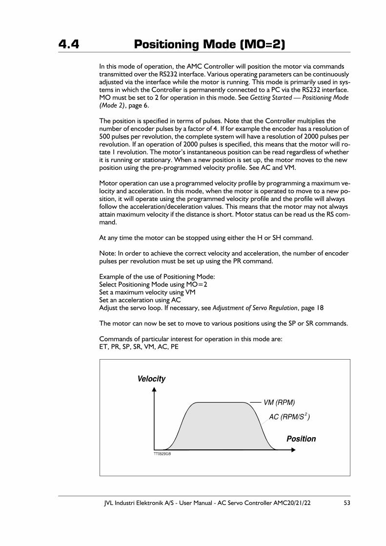
JVL Industri Elektronik A/S - User Manual - AC Servo Controller AMC20/21/22 53
4.4 Positioning Mode (MO=2)
In this mode of operation, the AMC Controller will position the motor via commands transmitted over the RS232 interface. Various operating parameters can be continuously adjusted via the interface while the motor is running. This mode is primarily used in sys-tems in which the Controller is permanently connected to a PC via the RS232 interface. MO must be set to 2 for operation in this mode. See Getting Started — Positioning Mode (Mode 2), page 6.
The position is specified in terms of pulses. Note that the Controller multiplies the number of encoder pulses by a factor of 4. If for example the encoder has a resolution of 500 pulses per revolution, the complete system will have a resolution of 2000 pulses per revolution. If an operation of 2000 pulses is specified, this means that the motor will ro-tate 1 revolution. The motor’s instantaneous position can be read regardless of whether it is running or stationary. When a new position is set up, the motor moves to the new position using the pre-programmed velocity profile. See AC and VM.
Motor operation can use a programmed velocity profile by programming a maximum ve-locity and acceleration. In this mode, when the motor is operated to move to a new po-sition, it will operate using the programmed velocity profile and the profile will always follow the acceleration/deceleration values. This means that the motor may not always attain maximum velocity if the distance is short. Motor status can be read us the RS com-mand.
At any time the motor can be stopped using either the H or SH command.
Note: In order to achieve the correct velocity and acceleration, the number of encoder pulses per revolution must be set up using the PR command.
Example of the use of Positioning Mode:Select Positioning Mode using MO=2Set a maximum velocity using VMSet an acceleration using ACAdjust the servo loop. If necessary, see Adjustment of Servo Regulation, page 18
The motor can now be set to move to various positions using the SP or SR commands.
Commands of particular interest for operation in this mode are:ET, PR, SP, SR, VM, AC, PE
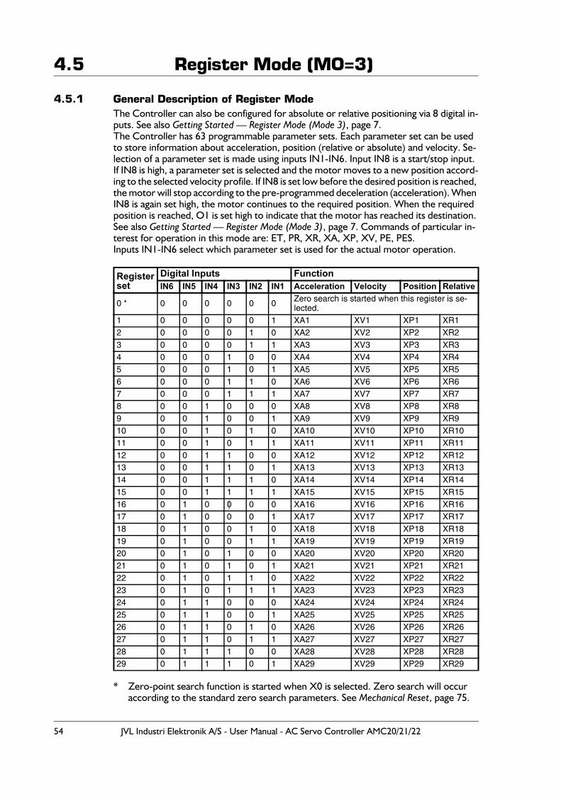
54 JVL Industri Elektronik A/S - User Manual - AC Servo Controller AMC20/21/22
4.5 Register Mode (MO=3)
4.5.1 General Description of Register ModeThe Controller can also be configured for absolute or relative positioning via 8 digital in-puts. See also Getting Started — Register Mode (Mode 3), page 7.The Controller has 63 programmable parameter sets. Each parameter set can be used to store information about acceleration, position (relative or absolute) and velocity. Se-lection of a parameter set is made using inputs IN1-IN6. Input IN8 is a start/stop input.If IN8 is high, a parameter set is selected and the motor moves to a new position accord-ing to the selected velocity profile. If IN8 is set low before the desired position is reached, the motor will stop according to the pre-programmed deceleration (acceleration). When IN8 is again set high, the motor continues to the required position. When the required position is reached, O1 is set high to indicate that the motor has reached its destination. See also Getting Started — Register Mode (Mode 3), page 7. Commands of particular in-terest for operation in this mode are: ET, PR, XR, XA, XP, XV, PE, PES.Inputs IN1-IN6 select which parameter set is used for the actual motor operation.
* Zero-point search function is started when X0 is selected. Zero search will occuraccording to the standard zero search parameters. See Mechanical Reset, page 75.
Registerset
Digital Inputs FunctionIN6 IN5 IN4 IN3 IN2 IN1 Acceleration Velocity Position Relative
0 * 0 0 0 0 0 0 Zero search is started when this register is se-lected.
1 0 0 0 0 0 1 XA1 XV1 XP1 XR12 0 0 0 0 1 0 XA2 XV2 XP2 XR23 0 0 0 0 1 1 XA3 XV3 XP3 XR34 0 0 0 1 0 0 XA4 XV4 XP4 XR45 0 0 0 1 0 1 XA5 XV5 XP5 XR56 0 0 0 1 1 0 XA6 XV6 XP6 XR67 0 0 0 1 1 1 XA7 XV7 XP7 XR78 0 0 1 0 0 0 XA8 XV8 XP8 XR89 0 0 1 0 0 1 XA9 XV9 XP9 XR910 0 0 1 0 1 0 XA10 XV10 XP10 XR1011 0 0 1 0 1 1 XA11 XV11 XP11 XR1112 0 0 1 1 0 0 XA12 XV12 XP12 XR1213 0 0 1 1 0 1 XA13 XV13 XP13 XR1314 0 0 1 1 1 0 XA14 XV14 XP14 XR1415 0 0 1 1 1 1 XA15 XV15 XP15 XR1516 0 1 0 0 0 0 XA16 XV16 XP16 XR1617 0 1 0 0 0 1 XA17 XV17 XP17 XR1718 0 1 0 0 1 0 XA18 XV18 XP18 XR1819 0 1 0 0 1 1 XA19 XV19 XP19 XR1920 0 1 0 1 0 0 XA20 XV20 XP20 XR2021 0 1 0 1 0 1 XA21 XV21 XP21 XR2122 0 1 0 1 1 0 XA22 XV22 XP22 XR2223 0 1 0 1 1 1 XA23 XV23 XP23 XR2324 0 1 1 0 0 0 XA24 XV24 XP24 XR2425 0 1 1 0 0 1 XA25 XV25 XP25 XR2526 0 1 1 0 1 0 XA26 XV26 XP26 XR2627 0 1 1 0 1 1 XA27 XV27 XP27 XR2728 0 1 1 1 0 0 XA28 XV28 XP28 XR2829 0 1 1 1 0 1 XA29 XV29 XP29 XR29
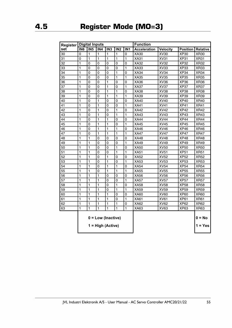
JVL Industri Elektronik A/S - User Manual - AC Servo Controller AMC20/21/22 55
4.5 Register Mode (MO=3)
Registerset
Digital Inputs FunctionIN6 IN5 IN4 IN3 IN2 IN1 Acceleration Velocity Position Relative
30 0 1 1 1 1 0 XA30 XV30 XP30 XR3031 0 1 1 1 1 1 XA31 XV31 XP31 XR3132 1 0 0 0 0 0 XA32 XV32 XP32 XR3233 1 0 0 0 0 1 XA33 XV33 XP33 XR3334 1 0 0 0 1 0 XA34 XV34 XP34 XR3435 1 0 0 0 1 1 XA35 XV35 XP35 XR3536 1 0 0 1 0 0 XA36 XV36 XP36 XR3637 1 0 0 1 0 1 XA37 XV37 XP37 XR3738 1 0 0 1 1 0 XA38 XV38 XP38 XR3839 1 0 0 1 1 1 XA39 XV39 XP39 XR3940 1 0 1 0 0 0 XA40 XV40 XP40 XR4041 1 0 1 0 0 1 XA41 XV41 XP41 XR4142 1 0 1 0 1 0 XA42 XV42 XP42 XR4243 1 0 1 0 1 1 XA43 XV43 XP43 XR4344 1 0 1 1 0 0 XA44 XV44 XP44 XR4445 1 0 1 1 0 1 XA45 XV45 XP45 XR4546 1 0 1 1 1 0 XA46 XV46 XP46 XR4647 1 0 1 1 1 1 XA47 XV47 XP47 XR4748 1 1 0 0 0 0 XA48 XV48 XP48 XR4849 1 1 0 0 0 1 XA49 XV49 XP49 XR4950 1 1 0 0 1 0 XA50 XV50 XP50 XR5051 1 1 0 0 1 1 XA51 XV51 XP51 XR5152 1 1 0 1 0 0 XA52 XV52 XP52 XR5253 1 1 0 1 0 1 XA53 XV53 XP53 XR5354 1 1 0 1 1 0 XA54 XV54 XP54 XR5455 1 1 0 1 1 1 XA55 XV55 XP55 XR5556 1 1 1 0 0 0 XA56 XV56 XP56 XR5657 1 1 1 0 0 1 XA57 XV57 XP57 XR5758 1 1 1 0 1 0 XA58 XV58 XP58 XR5859 1 1 1 0 1 1 XA59 XV59 XP59 XR5960 1 1 1 1 0 0 XA60 XV60 XP60 XR6061 1 1 1 1 0 1 XA61 XV61 XP61 XR6162 1 1 1 1 1 0 XA62 XV62 XP62 XR6263 1 1 1 1 1 1 XA63 XV63 XP63 XR63
0 = Low (Inactive)
1 = High (Active)
0 = No
1 = Yes
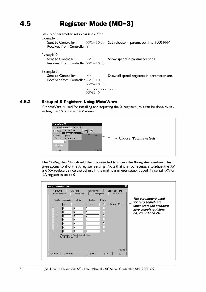
56 JVL Industri Elektronik A/S - User Manual - AC Servo Controller AMC20/21/22
4.5 Register Mode (MO=3)Set-up of parameter set in On line editor. Example 1:
Sent to Controller XV1=1000 Set velocity in param. set 1 to 1000 RPM.Received from Controller Y
Example 2:Sent to Controller XV1 Show speed in parameter set 1Received from Controller XV1=1000
Example 3: Sent to Controller XV Show all speed registers in parameter setsReceived from Controller XV1=10
XV2=1000.............XV63=0
4.5.2 Setup of X Registers Using MotoWareIf MotoWare is used for installing and adjusting the X registers, this can be done by se-lecting the "Parameter Sets" menu.
The "X-Registers" tab should then be selected to access the X-register window. This gives access to all of the X register settings. Note that it is not necessary to adjust the XV and XA registers since the default in the main parameter setup is used if a certain XV or XA register is set to 0.
Choose "Parameter Sets"
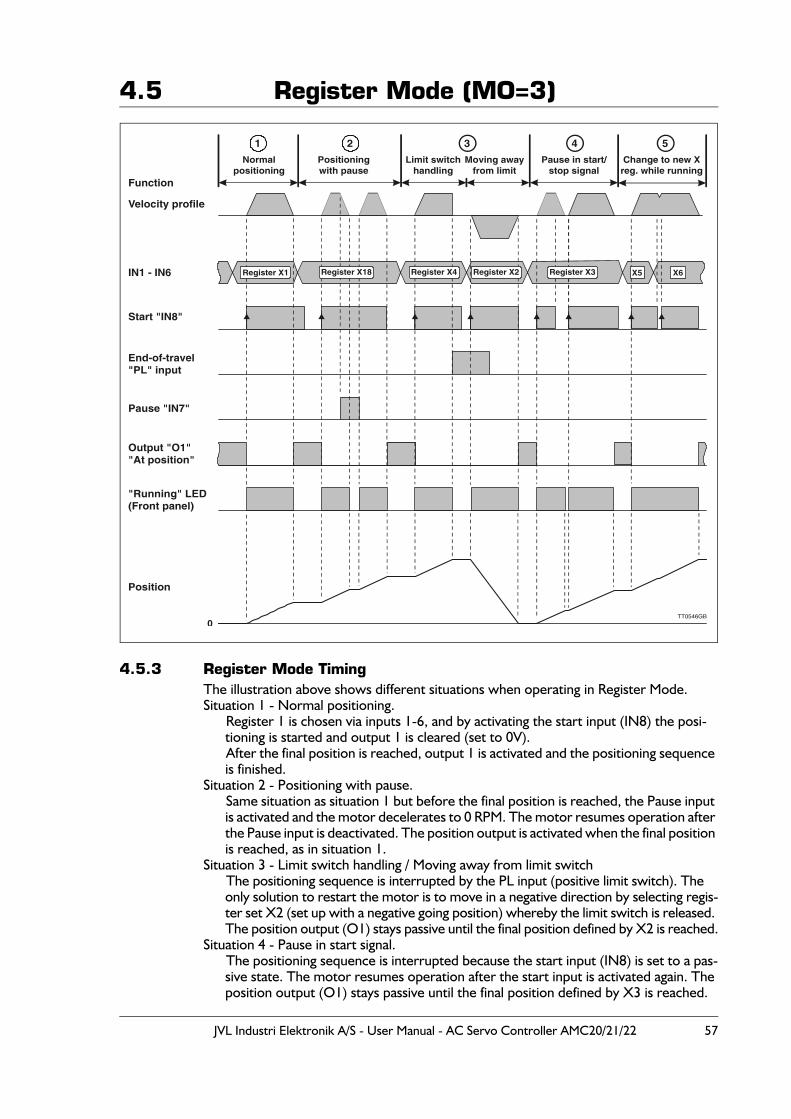
JVL Industri Elektronik A/S - User Manual - AC Servo Controller AMC20/21/22 57
4.5 Register Mode (MO=3)
4.5.3 Register Mode TimingThe illustration above shows different situations when operating in Register Mode.Situation 1 - Normal positioning.
Register 1 is chosen via inputs 1-6, and by activating the start input (IN8) the posi-tioning is started and output 1 is cleared (set to 0V).After the final position is reached, output 1 is activated and the positioning sequence is finished.
Situation 2 - Positioning with pause.Same situation as situation 1 but before the final position is reached, the Pause input is activated and the motor decelerates to 0 RPM. The motor resumes operation after the Pause input is deactivated. The position output is activated when the final position is reached, as in situation 1.
Situation 3 - Limit switch handling / Moving away from limit switchThe positioning sequence is interrupted by the PL input (positive limit switch). The only solution to restart the motor is to move in a negative direction by selecting regis-ter set X2 (set up with a negative going position) whereby the limit switch is released. The position output (O1) stays passive until the final position defined by X2 is reached.
Situation 4 - Pause in start signal.The positioning sequence is interrupted because the start input (IN8) is set to a pas-sive state. The motor resumes operation after the start input is activated again. The position output (O1) stays passive until the final position defined by X3 is reached.
Velocity profile
Function
Start "IN8"
IN1 - IN6
Pause "IN7"
End-of-travel"PL" input
Output "O1""At position"
"Running" LED(Front panel)
Position
Register X4 Register X2 Register X3Register X18Register X1
TT0546GB
Normalpositioning
Positioningwith pause
Limit switchhandling
Moving awayfrom limit
Pause in start/stop signal
Change to new Xreg. while running
0
X5 X6
1 2 3 4 5
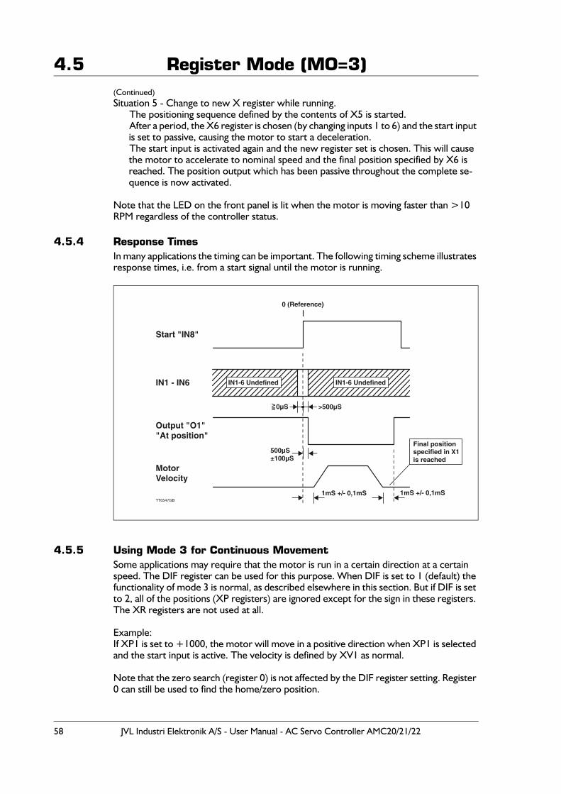
58 JVL Industri Elektronik A/S - User Manual - AC Servo Controller AMC20/21/22
4.5 Register Mode (MO=3)(Continued)Situation 5 - Change to new X register while running.
The positioning sequence defined by the contents of X5 is started.After a period, the X6 register is chosen (by changing inputs 1 to 6) and the start input is set to passive, causing the motor to start a deceleration. The start input is activated again and the new register set is chosen. This will cause the motor to accelerate to nominal speed and the final position specified by X6 is reached. The position output which has been passive throughout the complete se-quence is now activated.
Note that the LED on the front panel is lit when the motor is moving faster than >10 RPM regardless of the controller status.
4.5.4 Response TimesIn many applications the timing can be important. The following timing scheme illustrates response times, i.e. from a start signal until the motor is running.
4.5.5 Using Mode 3 for Continuous MovementSome applications may require that the motor is run in a certain direction at a certain speed. The DIF register can be used for this purpose. When DIF is set to 1 (default) the functionality of mode 3 is normal, as described elsewhere in this section. But if DIF is set to 2, all of the positions (XP registers) are ignored except for the sign in these registers. The XR registers are not used at all.
Example:If XP1 is set to +1000, the motor will move in a positive direction when XP1 is selected and the start input is active. The velocity is defined by XV1 as normal.
Note that the zero search (register 0) is not affected by the DIF register setting. Register 0 can still be used to find the home/zero position.
MotorVelocity
Start "IN8"
IN1 - IN6
Output "O1""At position"
0 (Reference)
1mS +/- 0,1mS 1mS +/- 0,1mS
500µS±100µS
>500µS0µS>=
Final positionspecified in X1is reached
IN1-6 UndefinedIN1-6 Undefined
TT0547GB
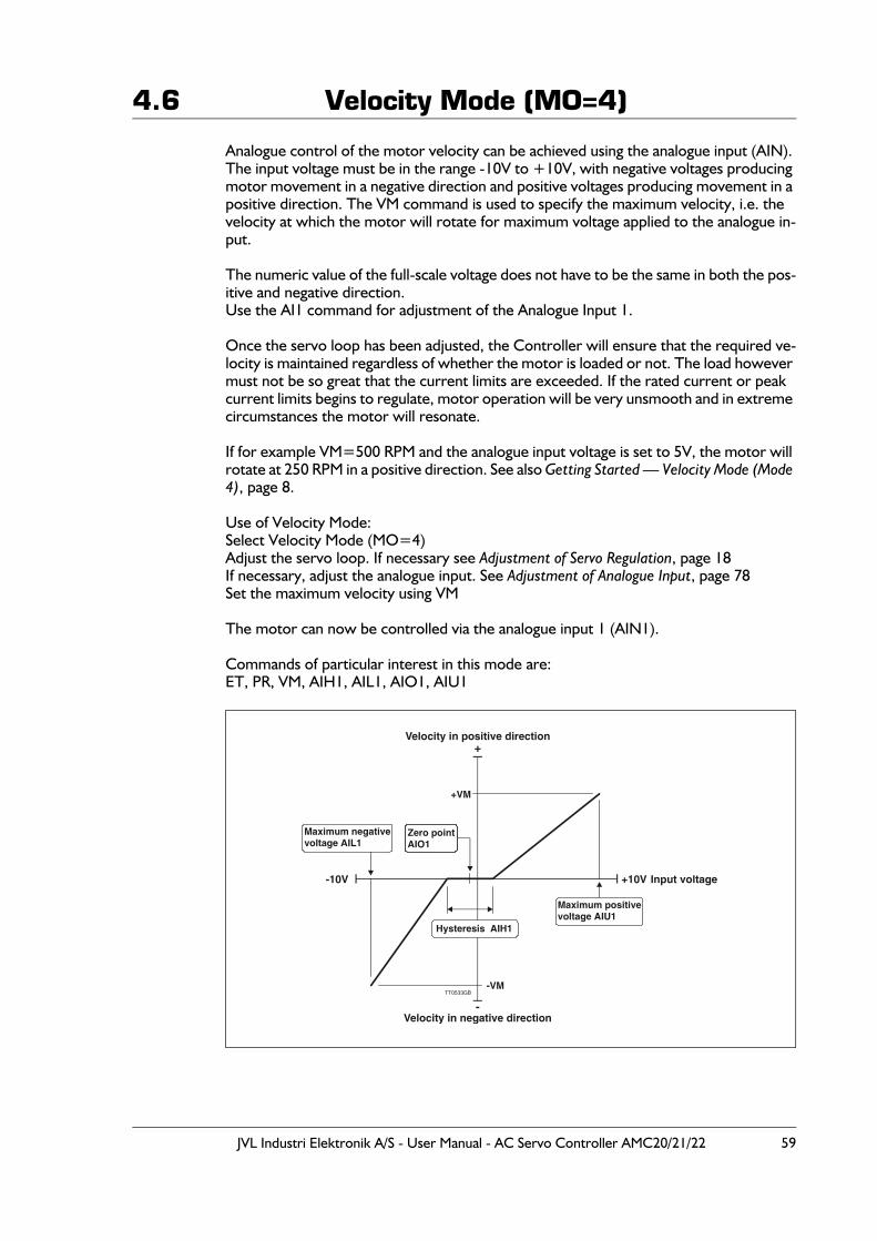
JVL Industri Elektronik A/S - User Manual - AC Servo Controller AMC20/21/22 59
4.6 Velocity Mode (MO=4)
Analogue control of the motor velocity can be achieved using the analogue input (AIN). The input voltage must be in the range -10V to +10V, with negative voltages producing motor movement in a negative direction and positive voltages producing movement in a positive direction. The VM command is used to specify the maximum velocity, i.e. the velocity at which the motor will rotate for maximum voltage applied to the analogue in-put.
The numeric value of the full-scale voltage does not have to be the same in both the pos-itive and negative direction.Use the AI1 command for adjustment of the Analogue Input 1.
Once the servo loop has been adjusted, the Controller will ensure that the required ve-locity is maintained regardless of whether the motor is loaded or not. The load however must not be so great that the current limits are exceeded. If the rated current or peak current limits begins to regulate, motor operation will be very unsmooth and in extreme circumstances the motor will resonate.
If for example VM=500 RPM and the analogue input voltage is set to 5V, the motor will rotate at 250 RPM in a positive direction. See also Getting Started — Velocity Mode (Mode 4), page 8.
Use of Velocity Mode:Select Velocity Mode (MO=4)Adjust the servo loop. If necessary see Adjustment of Servo Regulation, page 18If necessary, adjust the analogue input. See Adjustment of Analogue Input, page 78 Set the maximum velocity using VM
The motor can now be controlled via the analogue input 1 (AIN1).
Commands of particular interest in this mode are:ET, PR, VM, AIH1, AIL1, AIO1, AIU1
Input voltage
Velocity in positive direction
Velocity in negative direction
Maximum positivevoltage AIU1
Maximum negativevoltage AIL1
+
-
+10V-10V
Zero pointAIO1
Hysteresis AIH1
-VM
+VM
TT0533GB
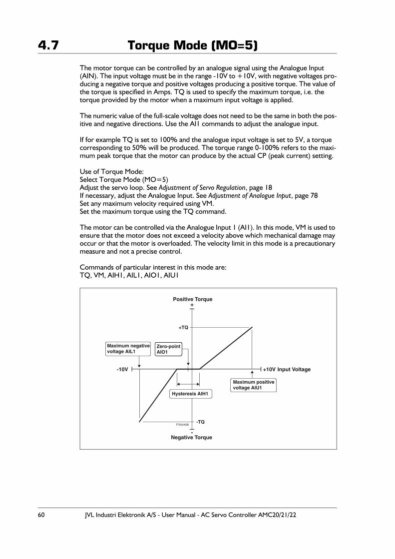
60 JVL Industri Elektronik A/S - User Manual - AC Servo Controller AMC20/21/22
4.7 Torque Mode (MO=5)
The motor torque can be controlled by an analogue signal using the Analogue Input (AIN). The input voltage must be in the range -10V to +10V, with negative voltages pro-ducing a negative torque and positive voltages producing a positive torque. The value of the torque is specified in Amps. TQ is used to specify the maximum torque, i.e. the torque provided by the motor when a maximum input voltage is applied.
The numeric value of the full-scale voltage does not need to be the same in both the pos-itive and negative directions. Use the AI1 commands to adjust the analogue input.
If for example TQ is set to 100% and the analogue input voltage is set to 5V, a torque corresponding to 50% will be produced. The torque range 0-100% refers to the maxi-mum peak torque that the motor can produce by the actual CP (peak current) setting.
Use of Torque Mode:Select Torque Mode (MO=5)Adjust the servo loop. See Adjustment of Servo Regulation, page 18If necessary, adjust the Analogue Input. See Adjustment of Analogue Input, page 78Set any maximum velocity required using VM.Set the maximum torque using the TQ command.
The motor can be controlled via the Analogue Input 1 (AI1). In this mode, VM is used to ensure that the motor does not exceed a velocity above which mechanical damage may occur or that the motor is overloaded. The velocity limit in this mode is a precautionary measure and not a precise control.
Commands of particular interest in this mode are:TQ, VM, AIH1, AIL1, AIO1, AIU1
Input Voltage
Positive Torque
Negative Torque
Maximum positivevoltage AIU1
Maximum negativevoltage AIL1
+
-
+10V-10V
Zero-pointAIO1
Hysteresis AIH1
-TQ
+TQ
TT0534GB
JVL Industri Elektronik A/S - User Manual - AC Servo Controller AMC20/21/22 61
4.8 Program Execution in the AMC2xP
4.8.1 General DescriptionThe AMC2x Servo Controller provides the additional feature that it can be programmed using a simple and flexible programming language which is built up around the interface command set. Thus all commands can be used for developing or executing programs. During program execution, all parameters in the Controller can be read or changed. All values that can be set and read using the same single command are called registers and can be used in arithmetic expressions.
Program execution is line based. A program can consist of up to 500 program lines, be-ginning with line number 0. A program line is executed every millisecond. The Controller can thus take care of all the functions required by an AC Servo Controller. For example, power consumption and average current are monitored and it is possible to communi-cate via the RS232 interface when a program is executed.
The programming language itself is very simple and resembles BASIC. The program is not compiled, but is interpreted during execution. This gives the advantage that in principle only a terminal program is required to program the Controller.
4.8.2 Use of Commands in a ProgramThe inclusion of a command, such as one of the "show value" commands, will result in the returned value being sent over the RS232 interface. For example, if the current ac-celeration is 100, the command AC alone will result in the following string on the inter-face: AC=100. The command AC=200 however will change the acceleration to 200. When a command is included in an arithmetic expression, the value of the register is sub-stituted into the expression. For example, the program line VM=AC+100 will set the maximum velocity to the value of the acceleration plus 100. When register values are in-cluded in expressions in this way, no account is taken of the implied units (velocity and acceleration in this case). When, for example, velocity is changed using the VM command, the effect on motor operation occurs instantaneously. Changes in motor parameters must therefore be made with great care.
Examples of the use of commands in a program:AC=330 // Set acceleration to 330 RPM/sVM=500 // Set max. velocity to 500 RPMSR=100000 // Advance the motor 100000 pulsesAP // Show actual position via the RS232 interface
4.8.3 User RegistersAll registers can be used for temporary storage of values. Since some registers have di-rect effect on motor movement, as mentioned above, the Controller is equipped with 500 user-definable registers denoted R0-R499. These can be used freely to store inter-mediate values. R0-R499 can be used and included in arithmetic expressions in the same way as any other parameter such as the motor parameters (VM, PR, CL, AC). The user registers can store values in the range -2.147.483.647 to +2.147.483.647 and can be saved in the Controller’s non-volatile memory using the command MS2. When the con-tents of the user registers are saved in non-volatile memory, they must be recalled using the MR1 command before they can be used.Examples of the use of user registers:R1=R2 // Set register 1 (R1) equal to register 2 (R2)R1=-R1 // Negate the value of register 1R1=-R2 // Negate the value of R2 and save the result in R1R3=R1*-R2 // Negate R2, multiply by R1 and save result in R3R1=KP*10 // Multiply KP by 10 and save the result in R1
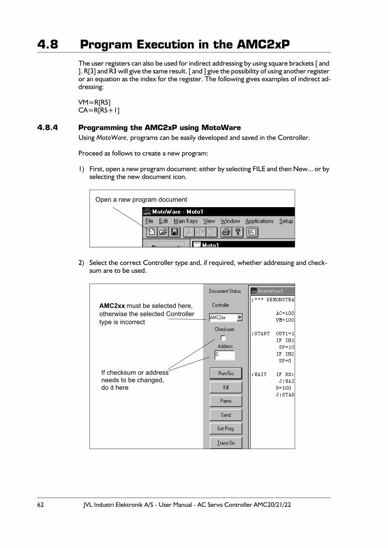
62 JVL Industri Elektronik A/S - User Manual - AC Servo Controller AMC20/21/22
4.8 Program Execution in the AMC2xPThe user registers can also be used for indirect addressing by using square brackets [ and ]. R[3] and R3 will give the same result. [ and ] give the possibility of using another register or an equation as the index for the register. The following gives examples of indirect ad-dressing:
VM=R[R5]CA=R[R5+1]
4.8.4 Programming the AMC2xP using MotoWareUsing MotoWare, programs can be easily developed and saved in the Controller.
Proceed as follows to create a new program:
1) First, open a new program document: either by selecting FILE and then New... or by selecting the new document icon.
2) Select the correct Controller type and, if required, whether addressing and check-sum are to be used.
Open a new program document
AMC2xx must be selected here,otherwise the selected Controller type is incorrect
If checksum or address
do it hereneeds to be changed,
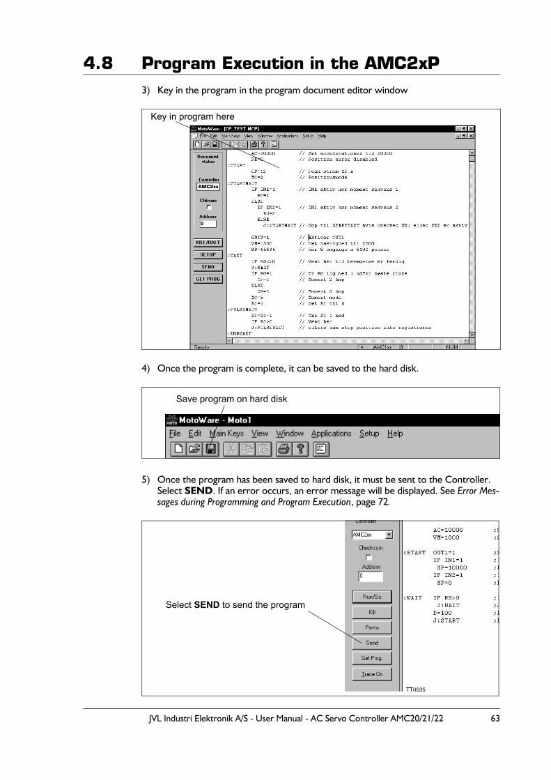
JVL Industri Elektronik A/S - User Manual - AC Servo Controller AMC20/21/22 63
4.8 Program Execution in the AMC2xP3) Key in the program in the program document editor window
4) Once the program is complete, it can be saved to the hard disk.
5) Once the program has been saved to hard disk, it must be sent to the Controller. Select SEND. If an error occurs, an error message will be displayed. See Error Mes-sages during Programming and Program Execution, page 72.
Key in program here
AMC2xx
Save program on hard disk
Select SEND to send the program

64 JVL Industri Elektronik A/S - User Manual - AC Servo Controller AMC20/21/22
4.8 Program Execution in the AMC2xP6) After SEND is selected the following dialogue box will appear.
This dialogue is used to decide which other parameters must be transferred together with the program (if any).Parameter setup: This item covers all the standard parameters such as Velocity, Servo
filter setup, and motor basic parameters. All parameters except X and R registers.
X-Registers : If X-Registers are selected, all the position and speed registers used in mode 3 are transferred together with the program.
User registers : If User registers are selected, all the user registers (R0-R499) are transferred together with the program.
Ok : Press Ok and the program will be transferred to the Controller in-cluding the selected register groups.
7) Once the program has been sent to the Controller, the dialogue box shown below is displayed. This provides several options. For example, you can choose to start the program automatically when the Controller is powered up. In this case Yes is selected followed by Save. The six command buttons have the following function:
Save/Online Editor : Save the program in non-volatile memory and open the On-Line Editor. When this option is selected, the MS command is sent to the Controller. Then the OnLine Editor is started. The program can then be executed using the GO command. It is important to use the OnLine Editor during tests. In the event of program errors, the Controller sends error messag-es which are automatically displayed in the OnLine Editor.
TT0566GB

JVL Industri Elektronik A/S - User Manual - AC Servo Controller AMC20/21/22 65
4.8 Program Execution in the AMC2xPSave and run Program : Save the program in non-volatile memory and start program
execution. When this option is selected, the MS command is sent to the Controller, followed by the GO command. The program is saved and then executed.
Run Program : Start the program.When this option is selected, the GO com-mand is sent to the Controller and program execution begins.
Save : Save the program in non-volatile memory.
OnLine Editor : Start the OnLine Editor directly. The OnLine Editor is opened and the program can be executed using the GO com-mand. It is important to use the OnLine Editor during tests. In the event of program errors, the Controller sends error messages which are automatically displayed in the OnLine Editor.
Continue (No Action) : Close the dialogue box without any further action.
4.8.5 Program SizeThe Controller is equipped with a program memory of 32kbyte. This memory will typi-cally be able to contain a program of 1000-2000 program lines. Program capacity is how-ever very dependent on which commands are used in a program. The "?" command in the online editor window can be used to display the actual program size in terms of % of total memory.See Show set-up (?), page 79.
66 JVL Industri Elektronik A/S - User Manual - AC Servo Controller AMC20/21/22
4.8 Program Execution in the AMC2xP
4.8.6 Arithmetic expressionsAll registers can be assigned a value by following the register name with an "equal to" sign "=", followed by an absolute value, a register name or an arithmetic expression. Absolute values, register values and the following four operators can be used in arithmetic expres-sions:
All calculations are performed either as 32-bit integers (-2.147.483.647 to+2.147.483.647) or as 32-bit decimal numbers ("floating- point") numbers. Integers aresigned and have approximately 10 significant digits. The 32 bits for decimal numbers areused as follows: 1 bit sign, 8 bit exponent and 23 bit mantissa. Decimal numbers can thusbe calculated with an accuracy of 23 bits, which gives approximately 7 significant digits.When calculations are made that involve large numbers, integers should be used. As ageneral rule, all expressions are calculated as integers. If a decimal number or registerwhich is expressed as a decimal (e.g. CP) is included anywhere in an expression, the en-tire calculation is performed as a decimal. The number 3 will be treated in an expressionas an integer, whereas 3.0 will result in the entire expression being calculated as a deci-mal. For integer calculations, any decimal remainder is discarded, also in intermediatecalculations. Calculation does not automatically occur as a decimal number even if theregister represented by the left-hand side of the expression is a decimal. Conversion ofthe result of the right-hand side of the equation occurs first when calculation is complete.Calculations that involve only integer values are performed much faster then decimal cal-culations. Therefore use decimal numbers only when necessary. The following examplesillustrate calculations of expressions. The following register values are assumed: IN1= 1,R1=2, AC=500, CP=1.5 and VM=100
R4=3/2+3/2 // R4 is assigned the value 2R4=3.0/2+3/2 // R4 is assigned the value 3CP=7/3+3/2 // CP is assigned the value 3.0CP=7.0/3+3/2 // CP is assigned the value 3.8R4=AC/VM*CP // R4 is assigned the value 7CP=AC/VM*CP // CP is assigned the value 7.5R4=IN1*35+CP*AC // R4 is assigned the value 785R4=IN1*35+(R1-AC)*2--2*(7+3*(VM-50)) // R4 is assigned the value -647
4.8.7 Operator Precedence and Order of EvaluationThe following table gives the rules of operator precedence and order of evaluation for operators that can be used in arithmetic and/or logical expressions. Operators on the same line of the table have the same rank, i.e. multiplication * and division / are ranked equally and an expression is evaluated from left to right. For example, 2*35/3 results in a value of 23, and 35/3*2 gives a value of 22 (note integer arithmetic is used here). The table is listed in order of precedence. Thus * and / have a higher rank than addition + and subtraction -. This means that multiplication and division are calculated first. For ex-ample, 35+3*2 gives the result 41. Parentheses "( )" can be used to change the order of evaluation of arithmetic operators. For example, the expression (35+3)*2 results in a value of 76.
Arithmetic operators used in expressions:
+ addition
- subtraction
* multiplication
/ division
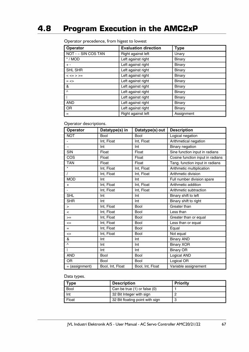
JVL Industri Elektronik A/S - User Manual - AC Servo Controller AMC20/21/22 67
4.8 Program Execution in the AMC2xPOperator precedence, from higest to lowest
Operator descriptions.
Data types.
Operator Evaluation direction TypeNOT - ~ SIN COS TAN Right against left Unary* / MOD Left against right Binary+ - Left against right BinarySHL SHR Left against right Binary< <= > >= Left against right Binary= <> Left against right Binary& Left against right Binary^ Left against right Binary| Left against right BinaryAND Left against right BinaryOR Left against right Binary= Right against left Assignment
Operator Datatype(s) in Datatype(s) out DescriptionNOT Bool Bool Logical negation- Int, Float Int, Float Arithmetical negation~ Int Int Binary negationSIN Float Float Sine function input in radiansCOS Float Float Cosine function input in radiansTAN Float Float Tang. function input in radians* Int, Float Int, Float Arithmetic multiplication/ Int, Float Int, Float Arithmetic divisionMOD Int Int Full number division spare+ Int, Float Int, Float Arithmetic addition- Int, Float Int, Float Arithmetic subtractionSHL Int Int Binary shift to leftSHR Int Int Binary shift to right> Int, Float Bool Greater than< Int, Float Bool Less than>= Int, Float Bool Greater than or equal<= Int, Float Bool Less than or equal= Int, Float Bool Equal<> Int, Float Bool Not equal& Int Int Binary AND^ Int Int Binary XOR| Int Int Binary ORAND Bool Bool Logical ANDOR Bool Bool Logical OR= (assignment) Bool, Int, Float Bool, Int, Float Variable assignement
Type Description PriorityBool Can be true (1) or false (0) 1Int 32 Bit Integer with sign 2Float 32 Bit floating point with sign 3
68 JVL Industri Elektronik A/S - User Manual - AC Servo Controller AMC20/21/22
4.8 Program Execution in the AMC2xPThe datatype is automatically converted into the type which the operator can use. If a floating point value is converted to an integer the nearest value is chosen.If the operator is working with to different data types the data type with the lowest pri-ority is converted into the same type as the data type with the highest priority.Example: A floating point value is added to an integer therefore the integer is before the addition converted into a floating point value.
Logical equations:Logical equations are used to evaluate whether one of more conditions are fulfilled in connection with IF statements. Formally the syntax is as follows:
Logical equation::= logical expression { OR logical expression }logical expression::= logical factor { AND logical factor }logical factor::= value rel_op value(where rel_op is <, >, =, <=, >= or <>).value::= register or arithmetic expression
Logical equations may use ordinary arithmetic expressions, registers, relational opera-tors (<, >, =, <=, >= or <>) and logical operators (AND and OR). The order of evaluation for OR and AND cannot be changed using parentheses "( )". A logical expres-sion must be specified before and after an AND or an OR operator. A logical expression must contain a relational operator. Thus it is not sufficient to specify an expression such as AC OR VM but an expression such as AC>0 OR VM>0 is legal. As many relational and logical operators as required may be used providing the formal requirements are met. A logical equation may also include arithmetic expressions in which the result is compared to value, register or another arithmetic expression. The following illustrates examples of logical equations:
Equations : Comments:IN1=1 OR IN2=1 OR IN3=1 AND IN4=1 Is true if IN1 or IN2 is 1 or IN3 and IN4
is 1.
AC>8*(4-3) AND IN1=IN2*IN3*IN4 Is true if the acceleration is greater than 8 and when IN1 is 1 at the same time as IN2, IN3 and IN4 are 1 or IN1=0 and only one of IN2, IN3 or IN4 is 0.
AC<>VM*IN1 Is always true when the acceleration is greater than zero and different from the velocity.
The following are illegal:(AC>45 OR VM<67) AND AC<>VM Parentheses cannot be used to change
the order of evaluation of OR and AND the right bracket is expected after 45.
IN1 OR IN2 Relational operator missing.
JVL Industri Elektronik A/S - User Manual - AC Servo Controller AMC20/21/22 69
4.8 Program Execution in the AMC2xPExamples:
R1= 3.5 + 5 * 7 => R1=39
First of all 5*7 will be calculated since * (multiply) has the higest precedence. The result of this calculation will be an integer (Int).Now the floating point value 3.5 + the integer 35 is processed. In the first place the value 35 will be converted to a floating point value and afterwards the addition will be done.The result will be the floating point value 38.5.
Since R0 is an integer the value will be converted into an integer (39) which is transfered to the register R1.
R1 = 7*3*3.5 => R1=74
First of all 7*3 will be calculated since * (multiply) is evaluated from left against right. The result of this is the integer 21. Secondly 21*3.5 is calculated but in the first place 21 is converted into a floating point value. The result is 73.5 which is converted to an integer and transfered to the register R1.
R1 = 47/2/2.0 => R1=12
First of all 47/2 will be calculated as a integer division since a division is evaluated from left to right. The result is 23. Secondly 23/2.0 is calculated. This is done by converting 23 to a floating point value. The result is presented as a floating point value of 11.5 which is converted to the integer value 12. In the end the result 12 is transfered to R1.
R1 = NOT 12 + 7 => R1=7
First of all NOT 12 is processed since NOT has the highest precedence.Since NOT only can function at a "Bool" type, the state of 12 will be converted to such one. The result of this is 1 (true). The NOT operator will secondly do a negation of this value with the result 0 (false). In the end the (Bool)0 is added to the integer 7. The (Bool)0 will at the first place be converted to an integer and thereafter added to 7. The result will therefore be 7.
70 JVL Industri Elektronik A/S - User Manual - AC Servo Controller AMC20/21/22
4.8 Program Execution in the AMC2xP
4.8.8 IF StatementLogical expressions can be evaluated using an IF statement. Together with ELSE, the IF statement can be used to express "decisions" within the programming sequence. Formal-ly the syntax for the IF statement is as follows:
IF expressionaction1
ELSEaction2
in which the ELSE clause is optional. The conditional test is performed by evaluating ex-pression. If it is true, action1 is carried out. If expression is false, and if an ELSE clause is included, then action2 is carried out. The IF statement is line based: action1 must be spec-ified on the lines following the IF statement, and if an ELSE clause is used, ELSE and action2 must be specified on the following lines. action1 can include several command lines terminated by ELSE or ENDIF. If action2 consist of several lines the sequence must be terminated by ENDIF, otherwise the IF ELSE statement will only include first line and the following lines will always be executed. Because of the above, the following program segment will not work:
IF IN1=1 // NB this program segment will not workIF IN2=1ACELSEVM
If IN1 is 1, the program segment will work since the following line IF IN=2 will be eval-uated. If however IN1 is 0, the line IF IN2=1 will be skipped and the AC command ex-ecuted. The next line begins an ELSE clause. Lines following an ELSE are only executed if a preceding IF statement has been evaluated false, which is not the case in this example.
A solution to the above could be:
IF IN1=0 // Execute next line if IN1 is 0J:NN // Jump to label NN
IF IN2=1 // Execute next line if IN2 is 1AC // Show acceleration on RS232 interface
ELSE // Execute next line if IN2 is 0VM // Show velocity on RS232 interface
:NN
Or the solution could also be:
IF IN1=1/BEGINIF IN2=1ACELSEVMEND
JVL Industri Elektronik A/S - User Manual - AC Servo Controller AMC20/21/22 71
4.8 Program Execution in the AMC2xPThe following general construct:
IF expressionactionELSEBEGINIF expressionactionELSEBEGINIF expressionactionELSEactionENDEND
occurs so often, that a brief explanation is given here. This sequence of IF statements is the most general way of making conditional tests between many possible cases. The ex-pressions are evaluated in sequence and if one of the expressions is true, the action as-sociated with that expression is performed and the entire chain terminated. As always, the code for each action is a program line specifying a command.
The final ELSE clause takes care of the situation when none of the previous conditions have been met. If no action is required in this case, the final ELSE clause:
ELSEaction
can be omitted. To illustrate a conditional test involving 3 branches, the following exam-ples shows how a program segment can be used to wait for input from IN1 or IN2. When IN1 is active (1), the acceleration is set to 500 and the program continues. If IN1 is inac-tive (0) and IN2 is active (1), the acceleration is set to 900 and the program continues.
:STARTIF IN1=1 // If IN1 is active, set AC=500
AC=500ELSEBEGIN
IF IN2=1 // If IN2 is active, set AC=900 AC=900
ELSE J:START // Jump to START if neither IN1 nor IN2 is active
END
Note: if more IF ELSE statements are used in connection, you must use BEGIN and END tags. (’{’ and ’}’ can be used instead of BEGIN and END)
72 JVL Industri Elektronik A/S - User Manual - AC Servo Controller AMC20/21/22
4.8 Program Execution in the AMC2xP
4.8.9 Error Messages during Programming and Program ExecutionThree types of error message can occur during programming and program execution: grammatical errors, syntactic errors, and errors during execution (runtime errors). A check for grammatical errors is carried out immediately during transfer of a program to the Controller. A check is made to ensure that the individual commands and operators exist, that absolute values are not too large, etc. A check is also made to ensure that com-mands are used in the correct context. For example, the following program line:
AC=H
will result in the error message: Error: This command must not be included in an equation. The H command is not of the register type. When a program is transferred via the Mo-toWare program editor and an error occurs, transfer is interrupted and the line contain-ing the error is highlighted.
When a program is interpreted during execution, any syntax errors are found while the program is in use. During testing therefore, it is important to use MotoWare with the On-Line editor window open. During execution, the Controller will automatically transmit any error messages. The following is an example:
VM=500AC=VM=CP // This line has incorrect syntax.IF VM>600VM=900
The above program segment will result in the error message: Error in line: 1 Des.: Syntax indicating a syntax error in line number 1.
VM=500R4=14AC=VMIF (VM>600 OR AC<>800// Right (closing bracket) missing after 600
The above program segment will result in the error message: Error in line: 3 Des.: Right parenthesis expected, indicating that a closing bracket is missing in line 3. (Remember that line numbering begins with line 0). If syntax errors occur, program execution is stopped.
The third type of error is those that occur during normal operation of a program that otherwise functions. These are not program errors as such but errors for example in the use of registers. Assigning a value which is too great or too small to a register during on-line control will normally result in the error message: E2: Out of range. During program execution however, this type of error will not generate error messages on the RS232 in-terface. Instead, information about previous errors is stored in a register which can be read using the ES command. These types of error can thus be handled during program execution and therefore do not require the program to be stopped. The following ex-ample illustrates how such errors can be avoided:
R1=ES0 // Clear any error messagesAC=100000 // Set acceleration to 100000IF ES0>0 // If error, ES0 is greater than 0AC=50000 // Set acceleration to 50000
resulting in the acceleration being set to 50000
JVL Industri Elektronik A/S - User Manual - AC Servo Controller AMC20/21/22 73
4.8 Program Execution in the AMC2xP
4.8.10 Jumping to Program Lines and the Use of LabelsThe Jump command J provides a facility for program control by jumping to a specified program line number. The Jump command can only be understood correctly by the Con-troller when it is used together with an absolute value, for example J50 (jump to line number 50). Using absolute line number values can give problems when programs are modified. When MotoWare is used however, labels can be used. MotoWare interprets and translates the individual labels and sends the correct command to the Controller. La-bel names may in principle consist of all displayable characters, but it is recommended that only numerals and the letters (a-z) are used since problems may occur if programs are moved between computers with different set-ups. Labels are case sensitive.
The following program segment:
:START IF IN1=1 // If IN1 is equal to 1, next line is executedJ:OK // Jump to label OKELSE // If IN1 is 0, execute line after ELSEJ:ERROR // Jump to label ERROR
:OK OUT5=1 // Set OUT5J:START // Jump to label START. Begin again
:ERROR OUT5=0 // Clear OUT5J:START // Jump to label START. Begin again
is translated to:
IF IN1=1J4ELSEJ6OUT5=1J0OUT5=0J0
4.8.11 Call of Sub-routineIf the same sequence of commands is used often, it is a good idea to create a sub-routine. A sub-routine is started with a label and terminated by the RET command. A sub-routine is called by the JS (Jump Subroutine) command. When the JS command is executed, pro-gram execution continues from the line number specified by the command in the form of a number or a label. When the RET (Return) command is encountered in the sub-rou-tine, the program returns to the main program at the line immediately after the JS com-mand and continues from there. The following gives an example of the use of a sub-routine:
R5=500R6=1000R1=5JS:TEST// set acceleration to 500R1=6JS:TEST// set acceleration to 1000J:END
:TEST AC=R[R1]RET
:END ....

74 JVL Industri Elektronik A/S - User Manual - AC Servo Controller AMC20/21/22
4.8 Program Execution in the AMC2xP
4.8.12 Pause in Program Execution (Delay)The D command pauses program execution. The break in msec. is defined by specifying D=pause or D(pause). While a program line is executed every 2 msec., the delay spec-ified will be in even multiples of msec. For example, D=13 will make a break for 14 msec.
R1=20 // Set R1 to 20D=R1 // Wait for 20 msec.
JVL Industri Elektronik A/S - User Manual - AC Servo Controller AMC20/21/22 75
4.9 Mechanical Reset
4.9.1 Zero Point Search FunctionThe motor can be brought to a known mechanical reference position, i.e. reset, using the zero-point search function. This is achieved using a sensor connected to the HM (Home) Input (default). The motor index signal can also be used. The parameter set ZA, ZV, ZD, ZR and ZM determine how the zero-point search is carried out. The parameter HML de-termines the Home Input’s active level. These parameters have the following functions:
4.9.2 Start a Zero-searchA zero-point search will be carried out after one of the following conditions is met:1. After start-up (power up) or after the Controller has received the RESET command.
This only occurs if ZR=1 (see above table).2. If the Controller receives the search zero command SZ.3. If the Controller is set to Mode 3 (Register Mode) and register 0 is selected.
During zero-search, the RS register will have the value 6.
4.9.3 Zero-search InterruptionA zero search can be stopped or paused in following ways:1. A Halt command (H) will stop the zero search immediately. The RS register will be
7 as usual when using halt. The actual position counter will have been updated during the zero-search and the contents will therefore be intact.The zero search can be restarted by using the commands mentioned above under "Start a Zero-search".
2. A Soft halt command (SH) will stop the zero search according to the acceleration/deceleration specified in the ZA register. The behaviour of the AP and RS register etc. will be the same as that using halt.
3. Changing to mode 0 (passive mode). This situation can happen after many situations such as when using the SON input or if a fatal error has occurred.The motor will be de-energised and the RS register will be set to 4.If the mode is changed back to an active mode (1-5) the RS register will be set to 0 and the zero-search is not continued.
Parameter Function
ZASpecifies acceleration/deceleration during zero-point search.The specified value is expressed in RPM/Second. If ZA isset to 0, the Controller will use the AC parameter during zero-point search.
ZD ZD=-1 results in zero-point search in a negative direction. (default).
ZD=1 results in zero-point search in apositive direction.
ZV Specifies the nominal velocity during zero-point search. If ZV is set to 0, theController will use the standard velocity VM parameter during zero-point search.
ZRZR=0 Specifies that the Controllerdoes not perform a zero-point searchwhen powered up.
ZR0=1 Specifies that the Controllerautomatically performs a zero-pointsearch when powered up.
HML HML=0 HM input active low. HML=1 HM input active high.
ZM
ZM = 0 (default) HM input is used for sensor. After a home seek is started, the motor will move until the HM in-put is activated.
ZM = 1 HM is disabled. The index (EZ in-put) is used as for home sensing. After a home seek is started, the motor will move until the index signal changes.
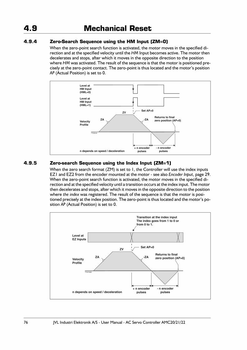
76 JVL Industri Elektronik A/S - User Manual - AC Servo Controller AMC20/21/22
4.9 Mechanical Reset
4.9.4 Zero-Search Sequence using the HM Input (ZM=0)When the zero-point search function is activated, the motor moves in the specified di-rection and at the specified velocity until the HM Input becomes active. The motor then decelerates and stops, after which it moves in the opposite direction to the position where HM was activated. The result of the sequence is that the motor is positioned pre-cisely at the zero-point contact. The zero-point is thus located and the motor’s position AP (Actual Position) is set to 0.
4.9.5 Zero-search Sequence using the Index Input (ZM=1)When the zero search format (ZM) is set to 1, the Controller will use the index inputs EZ1 and EZ2 from the encoder mounted at the motor - see also Encoder Input, page 29.When the zero-point search function is activated, the motor moves in the specified di-rection and at the specified velocity until a transition occurs at the index input. The motor then decelerates and stops, after which it moves in the opposite direction to the position where the index was registered. The result of the sequence is that the motor is posi-tioned precisely at the index position. The zero-point is thus located and the motor’s po-sition AP (Actual Position) is set to 0.
VelocityProfile
ZV
Level atHM Input(HML=1)
Level atHM Input(HML=0)
ZA -ZA
TT0560GB
Set AP=0
Returns to finalzero position (AP=0)
+ n encoderpulses
- n encoderpulsesn depends on speed / deceleration
VelocityProfile
ZV
Level atEZ Inputs
ZA -ZA
TT0579GB
Set AP=0
Returns to finalzero position (AP=0)
+ n encoderpulses
- n encoderpulsesn depends on speed / deceleration
Transition at the index inputThe index goes from 1 to 0 orfrom 0 to 1.
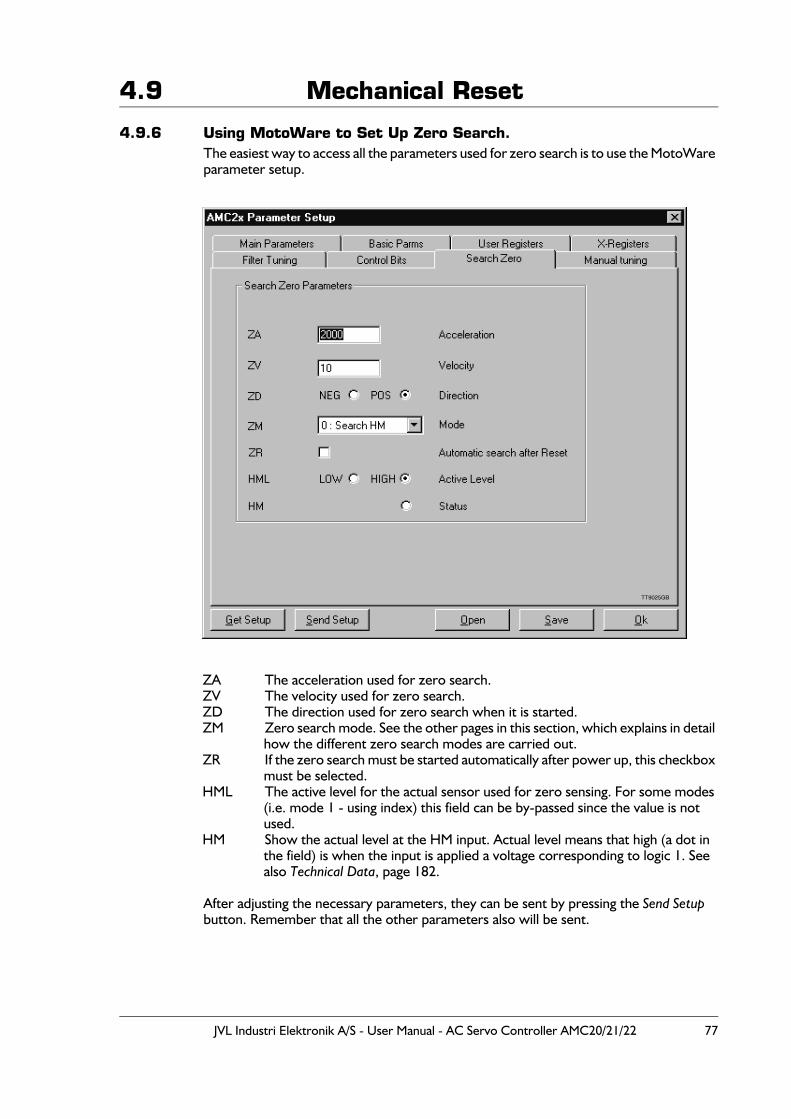
JVL Industri Elektronik A/S - User Manual - AC Servo Controller AMC20/21/22 77
4.9 Mechanical Reset
4.9.6 Using MotoWare to Set Up Zero Search.The easiest way to access all the parameters used for zero search is to use the MotoWare parameter setup.
ZA The acceleration used for zero search.ZV The velocity used for zero search.ZD The direction used for zero search when it is started.ZM Zero search mode. See the other pages in this section, which explains in detail
how the different zero search modes are carried out.ZR If the zero search must be started automatically after power up, this checkbox
must be selected.HML The active level for the actual sensor used for zero sensing. For some modes
(i.e. mode 1 - using index) this field can be by-passed since the value is not used.
HM Show the actual level at the HM input. Actual level means that high (a dot in the field) is when the input is applied a voltage corresponding to logic 1. See also Technical Data, page 182.
After adjusting the necessary parameters, they can be sent by pressing the Send Setup button. Remember that all the other parameters also will be sent.
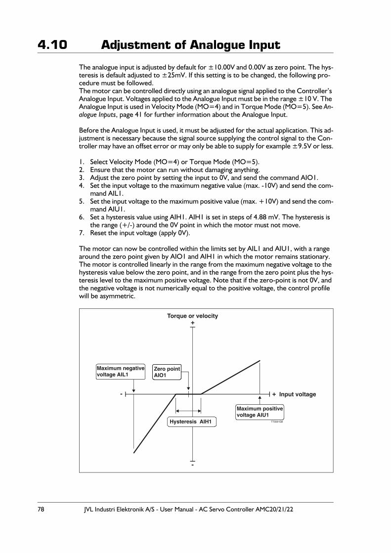
78 JVL Industri Elektronik A/S - User Manual - AC Servo Controller AMC20/21/22
4.10 Adjustment of Analogue Input
The analogue input is adjusted by default for ±10.00V and 0.00V as zero point. The hys-teresis is default adjusted to ±25mV. If this setting is to be changed, the following pro-cedure must be followed.The motor can be controlled directly using an analogue signal applied to the Controller’s Analogue Input. Voltages applied to the Analogue Input must be in the range ±10 V. The Analogue Input is used in Velocity Mode (MO=4) and in Torque Mode (MO=5). See An-alogue Inputs, page 41 for further information about the Analogue Input.
Before the Analogue Input is used, it must be adjusted for the actual application. This ad-justment is necessary because the signal source supplying the control signal to the Con-troller may have an offset error or may only be able to supply for example ±9.5V or less.
1. Select Velocity Mode (MO=4) or Torque Mode (MO=5).2. Ensure that the motor can run without damaging anything.3. Adjust the zero point by setting the input to 0V, and send the command AIO1.4. Set the input voltage to the maximum negative value (max. -10V) and send the com-
mand AIL1.5. Set the input voltage to the maximum positive value (max. +10V) and send the com-
mand AIU1.6. Set a hysteresis value using AIH1. AIH1 is set in steps of 4.88 mV. The hysteresis is
the range (+/-) around the 0V point in which the motor must not move.7. Reset the input voltage (apply 0V).
The motor can now be controlled within the limits set by AIL1 and AIU1, with a range around the zero point given by AIO1 and AIH1 in which the motor remains stationary. The motor is controlled linearly in the range from the maximum negative voltage to the hysteresis value below the zero point, and in the range from the zero point plus the hys-teresis level to the maximum positive voltage. Note that if the zero-point is not 0V, and the negative voltage is not numerically equal to the positive voltage, the control profile will be asymmetric.
Input voltage
Torque or velocity
Maximum positivevoltage AIU1
Maximum negativevoltage AIL1
+
-
+-
Zero pointAIO1
Hysteresis AIH1 TT0561GB
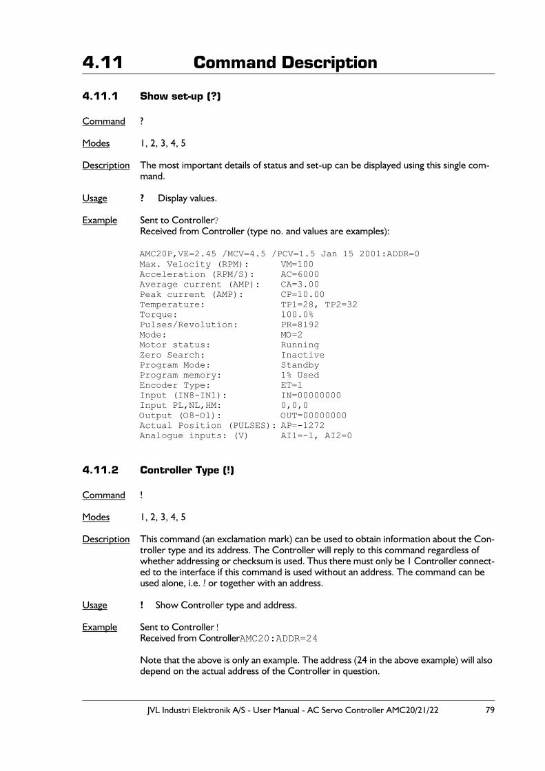
JVL Industri Elektronik A/S - User Manual - AC Servo Controller AMC20/21/22 79
4.11 Command Description
4.11.1 Show set-up (?)
Command ?
Modes 1, 2, 3, 4, 5
Description The most important details of status and set-up can be displayed using this single com-mand.
Usage ? Display values.
Example Sent to Controller?Received from Controller (type no. and values are examples):
AMC20P,VE=2.45 /MCV=4.5 /PCV=1.5 Jan 15 2001:ADDR=0Max. Velocity (RPM): VM=100Acceleration (RPM/S): AC=6000Average current (AMP): CA=3.00Peak current (AMP): CP=10.00Temperature: TP1=28, TP2=32Torque: 100.0%Pulses/Revolution: PR=8192Mode: MO=2Motor status: RunningZero Search: InactiveProgram Mode: StandbyProgram memory: 1% UsedEncoder Type: ET=1Input (IN8-IN1): IN=00000000Input PL,NL,HM: 0,0,0Output (O8-O1): OUT=00000000Actual Position (PULSES): AP=-1272Analogue inputs: (V) AI1=-1, AI2=0
4.11.2 Controller Type (!)
Command !
Modes 1, 2, 3, 4, 5
Description This command (an exclamation mark) can be used to obtain information about the Con-troller type and its address. The Controller will reply to this command regardless of whether addressing or checksum is used. Thus there must only be 1 Controller connect-ed to the interface if this command is used without an address. The command can be used alone, i.e. ! or together with an address.
Usage ! Show Controller type and address.
Example Sent to Controller!Received from ControllerAMC20:ADDR=24
Note that the above is only an example. The address (24 in the above example) will also depend on the actual address of the Controller in question.
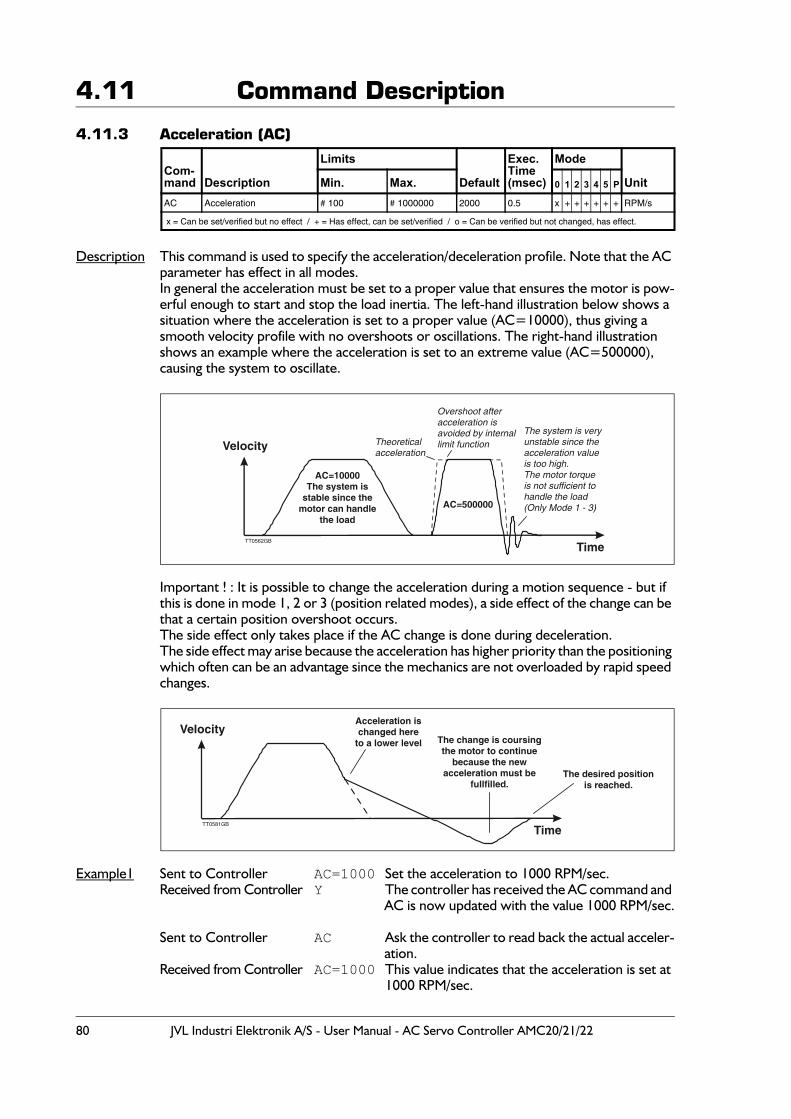
80 JVL Industri Elektronik A/S - User Manual - AC Servo Controller AMC20/21/22
4.11 Command Description
4.11.3 Acceleration (AC)
Description This command is used to specify the acceleration/deceleration profile. Note that the AC parameter has effect in all modes.In general the acceleration must be set to a proper value that ensures the motor is pow-erful enough to start and stop the load inertia. The left-hand illustration below shows a situation where the acceleration is set to a proper value (AC=10000), thus giving a smooth velocity profile with no overshoots or oscillations. The right-hand illustration shows an example where the acceleration is set to an extreme value (AC=500000), causing the system to oscillate.
Important ! : It is possible to change the acceleration during a motion sequence - but if this is done in mode 1, 2 or 3 (position related modes), a side effect of the change can be that a certain position overshoot occurs.The side effect only takes place if the AC change is done during deceleration.The side effect may arise because the acceleration has higher priority than the positioning which often can be an advantage since the mechanics are not overloaded by rapid speed changes.
Example1 Sent to Controller AC=1000 Set the acceleration to 1000 RPM/sec. Received from Controller Y The controller has received the AC command and
AC is now updated with the value 1000 RPM/sec.
Sent to Controller AC Ask the controller to read back the actual acceler-ation.
Received from Controller AC=1000 This value indicates that the acceleration is set at 1000 RPM/sec.
Com-mand Description
Limits
Default
Exec.Time(msec)
Mode
UnitMin. Max. 0 1 2 3 4 5 P
AC Acceleration # 100 # 1000000 2000 0.5 x + + + + + + RPM/s
x = Can be set/verified but no effect / + = Has effect, can be set/verified / o = Can be verified but not changed, has effect.
Velocity
AC=10000The system is
stable since themotor can handle
the load
AC=500000
TT0562GB
Time
The system is veryunstable since theacceleration value is too high.The motor torqueis not sufficient tohandle the load (Only Mode 1 - 3)
Overshoot afteracceleration isavoided by internallimit functionTheoretical
acceleration
VelocityAcceleration ischanged here
to a lower level The change is coursingthe motor to continue
because the newacceleration must be
fullfilled.The desired position
is reached.
TT0581GB
Time
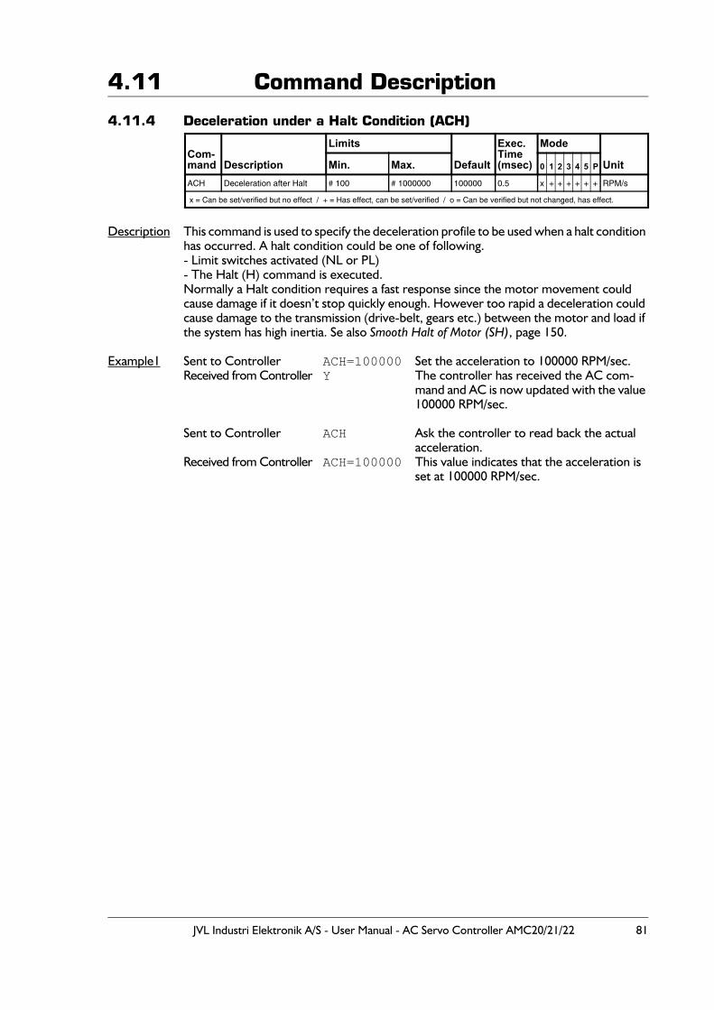
JVL Industri Elektronik A/S - User Manual - AC Servo Controller AMC20/21/22 81
4.11 Command Description
4.11.4 Deceleration under a Halt Condition (ACH)
Description This command is used to specify the deceleration profile to be used when a halt condition has occurred. A halt condition could be one of following.- Limit switches activated (NL or PL)- The Halt (H) command is executed.Normally a Halt condition requires a fast response since the motor movement could cause damage if it doesn’t stop quickly enough. However too rapid a deceleration could cause damage to the transmission (drive-belt, gears etc.) between the motor and load if the system has high inertia. Se also Smooth Halt of Motor (SH), page 150.
Example1 Sent to Controller ACH=100000 Set the acceleration to 100000 RPM/sec. Received from Controller Y The controller has received the AC com-
mand and AC is now updated with the value 100000 RPM/sec.
Sent to Controller ACH Ask the controller to read back the actual acceleration.
Received from Controller ACH=100000 This value indicates that the acceleration is set at 100000 RPM/sec.
Com-mand Description
Limits
Default
Exec.Time(msec)
Mode
UnitMin. Max. 0 1 2 3 4 5 P
ACH Deceleration after Halt # 100 # 1000000 100000 0.5 x + + + + + + RPM/s
x = Can be set/verified but no effect / + = Has effect, can be set/verified / o = Can be verified but not changed, has effect.
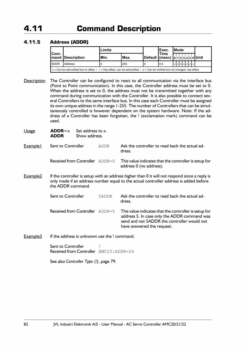
82 JVL Industri Elektronik A/S - User Manual - AC Servo Controller AMC20/21/22
4.11 Command Description
4.11.5 Address (ADDR)
Description The Controller can be configured to react to all communication via the interface bus(Point to Point communication). In this case, the Controller address must be set to 0.When the address is set to 0, the address must not be transmitted together with anycommand during communication with the Controller. It is also possible to connect sev-eral Controllers to the same interface bus. In this case each Controller must be assignedits own unique address in the range 1-255. The number of Controllers that can be simul-taneously controlled is however dependent on the system hardware. Note: If the ad-dress of a Controller has been forgotten, the ! (exclamation mark) command can beused.
Usage ADDR=x Set address to x.ADDR Show address.
Example1 Sent to Controller ADDR Ask the controller to read back the actual ad-dress.
Received from Controller ADDR=0 This value indicates that the controller is setup for
address 0 (no address).
Example2 If the controller is setup with an address higher than 0 it will not respond since a reply is only made if an address number equal to the actual controller address is added before the ADDR command.
Sent to Controller 5ADDR Ask the controller to read back the actual ad-dress.
Received from Controller ADDR=5 This value indicates that the controller is setup for
address 5. In case only the ADDR command was send and not 5ADDR the controller would not have answered the request.
Example3 If the address is unknown use the ! command.
Sent to Controller !Received from Controller AMC20:ADDR=24
See also Controller Type (!), page 79.
Com-mand Description
Limits
Default
Exec.Time(msec)
Mode
UnitMin. Max. 0 1 2 3 4 5 P
ADDR Address 0 255 0 0.5 + + + + + + +
x = Can be set/verified but no effect / + = Has effect, can be set/verified / o = Can be verified but not changed, has effect.
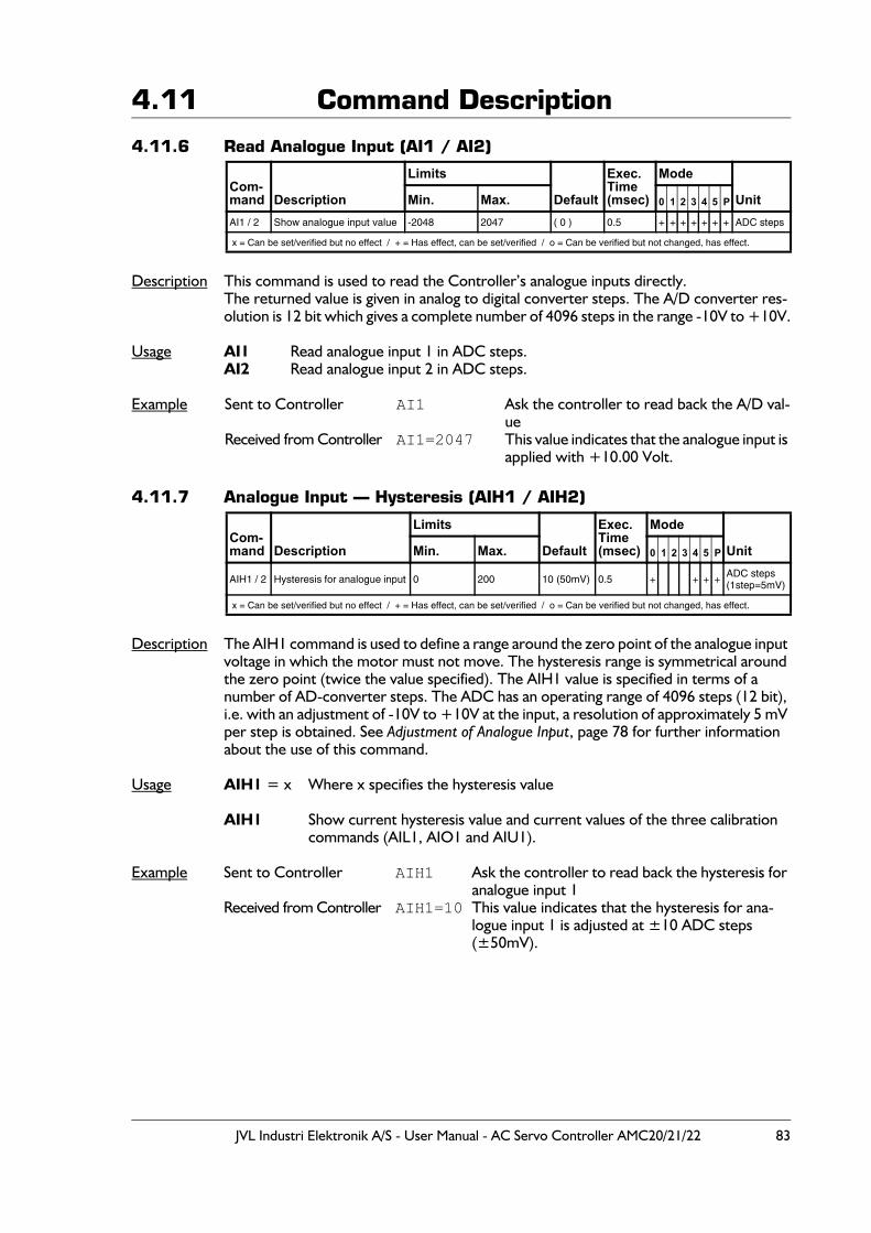
JVL Industri Elektronik A/S - User Manual - AC Servo Controller AMC20/21/22 83
4.11 Command Description
4.11.6 Read Analogue Input (AI1 / AI2)
Description This command is used to read the Controller’s analogue inputs directly.The returned value is given in analog to digital converter steps. The A/D converter res-olution is 12 bit which gives a complete number of 4096 steps in the range -10V to +10V.
Usage AI1 Read analogue input 1 in ADC steps. AI2 Read analogue input 2 in ADC steps.
Example Sent to Controller AI1 Ask the controller to read back the A/D val-ue
Received from Controller AI1=2047 This value indicates that the analogue input is applied with +10.00 Volt.
4.11.7 Analogue Input — Hysteresis (AIH1 / AIH2)
Description The AIH1 command is used to define a range around the zero point of the analogue input voltage in which the motor must not move. The hysteresis range is symmetrical around the zero point (twice the value specified). The AIH1 value is specified in terms of a number of AD-converter steps. The ADC has an operating range of 4096 steps (12 bit), i.e. with an adjustment of -10V to +10V at the input, a resolution of approximately 5 mV per step is obtained. See Adjustment of Analogue Input, page 78 for further information about the use of this command.
Usage AIH1 = x Where x specifies the hysteresis value
AIH1 Show current hysteresis value and current values of the three calibration commands (AIL1, AIO1 and AIU1).
Example Sent to Controller AIH1 Ask the controller to read back the hysteresis for analogue input 1
Received from Controller AIH1=10 This value indicates that the hysteresis for ana-logue input 1 is adjusted at ±10 ADC steps (±50mV).
Com-mand Description
Limits
Default
Exec.Time(msec)
Mode
UnitMin. Max. 0 1 2 3 4 5 P
AI1 / 2 Show analogue input value -2048 2047 ( 0 ) 0.5 + + + + + + + ADC steps
x = Can be set/verified but no effect / + = Has effect, can be set/verified / o = Can be verified but not changed, has effect.
Com-mand Description
Limits
Default
Exec.Time(msec)
Mode
UnitMin. Max. 0 1 2 3 4 5 P
AIH1 / 2 Hysteresis for analogue input 0 200 10 (50mV) 0.5 + + + + ADC steps(1step=5mV)
x = Can be set/verified but no effect / + = Has effect, can be set/verified / o = Can be verified but not changed, has effect.
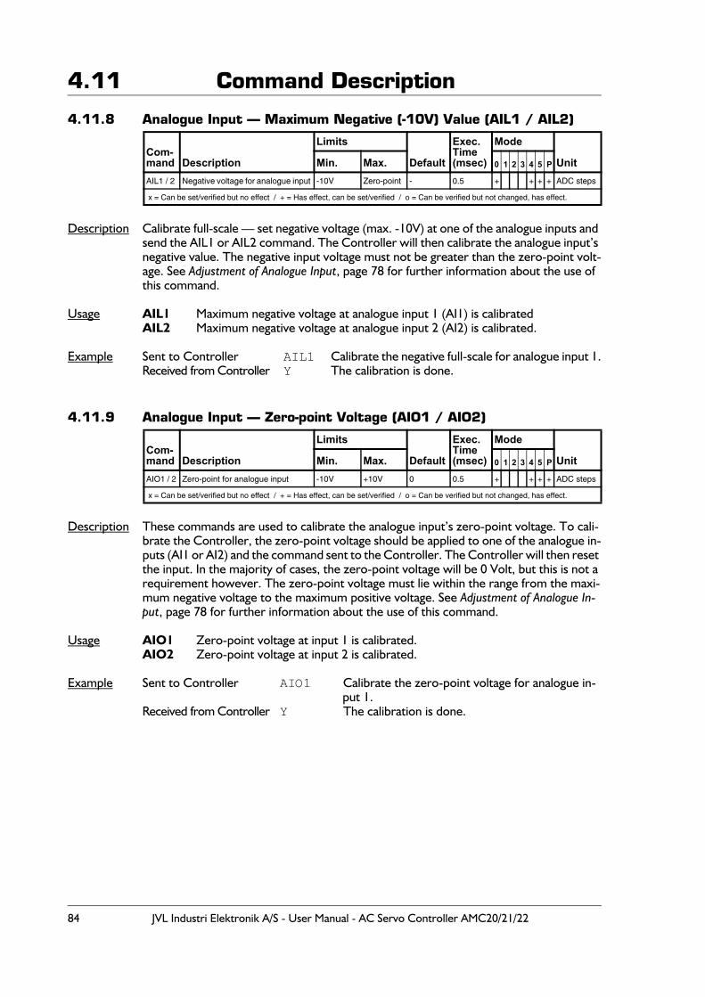
84 JVL Industri Elektronik A/S - User Manual - AC Servo Controller AMC20/21/22
4.11 Command Description
4.11.8 Analogue Input — Maximum Negative (-10V) Value (AIL1 / AIL2)
Description Calibrate full-scale — set negative voltage (max. -10V) at one of the analogue inputs and send the AIL1 or AIL2 command. The Controller will then calibrate the analogue input’s negative value. The negative input voltage must not be greater than the zero-point volt-age. See Adjustment of Analogue Input, page 78 for further information about the use of this command.
Usage AIL1 Maximum negative voltage at analogue input 1 (AI1) is calibratedAIL2 Maximum negative voltage at analogue input 2 (AI2) is calibrated.
Example Sent to Controller AIL1 Calibrate the negative full-scale for analogue input 1.Received from Controller Y The calibration is done.
4.11.9 Analogue Input — Zero-point Voltage (AIO1 / AIO2)
Description These commands are used to calibrate the analogue input’s zero-point voltage. To cali-brate the Controller, the zero-point voltage should be applied to one of the analogue in-puts (AI1 or AI2) and the command sent to the Controller. The Controller will then reset the input. In the majority of cases, the zero-point voltage will be 0 Volt, but this is not a requirement however. The zero-point voltage must lie within the range from the maxi-mum negative voltage to the maximum positive voltage. See Adjustment of Analogue In-put, page 78 for further information about the use of this command.
Usage AIO1 Zero-point voltage at input 1 is calibrated.AIO2 Zero-point voltage at input 2 is calibrated.
Example Sent to Controller AIO1 Calibrate the zero-point voltage for analogue in-put 1.
Received from Controller Y The calibration is done.
Com-mand Description
Limits
Default
Exec.Time(msec)
Mode
UnitMin. Max. 0 1 2 3 4 5 P
AIL1 / 2 Negative voltage for analogue input -10V Zero-point - 0.5 + + + + ADC steps
x = Can be set/verified but no effect / + = Has effect, can be set/verified / o = Can be verified but not changed, has effect.
Com-mand Description
Limits
Default
Exec.Time(msec)
Mode
UnitMin. Max. 0 1 2 3 4 5 P
AIO1 / 2 Zero-point for analogue input -10V +10V 0 0.5 + + + + ADC steps
x = Can be set/verified but no effect / + = Has effect, can be set/verified / o = Can be verified but not changed, has effect.
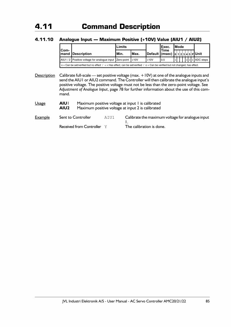
JVL Industri Elektronik A/S - User Manual - AC Servo Controller AMC20/21/22 85
4.11 Command Description
4.11.10 Analogue Input — Maximum Positive (+10V) Value (AIU1 / AIU2)
Description Calibrate full-scale — set positive voltage (max. +10V) at one of the analogue inputs and send the AIU1 or AIU2 command. The Controller will then calibrate the analogue input’s positive voltage. The positive voltage must not be less than the zero-point voltage. See Adjustment of Analogue Input, page 78 for further information about the use of this com-mand.
Usage AIU1 Maximum positive voltage at input 1 is calibratedAIU2 Maximum positive voltage at input 2 is calibrated
Example Sent to Controller AIU1 Calibrate the maximum voltage for analogue input 1.
Received from Controller Y The calibration is done.
Com-mand Description
Limits
Default
Exec.Time(msec)
Mode
UnitMin. Max. 0 1 2 3 4 5 P
AIU1 / 2 Positive voltage for analogue input Zero-point +10V +10V 0.5 + + + + ADC steps
x = Can be set/verified but no effect / + = Has effect, can be set/verified / o = Can be verified but not changed, has effect.
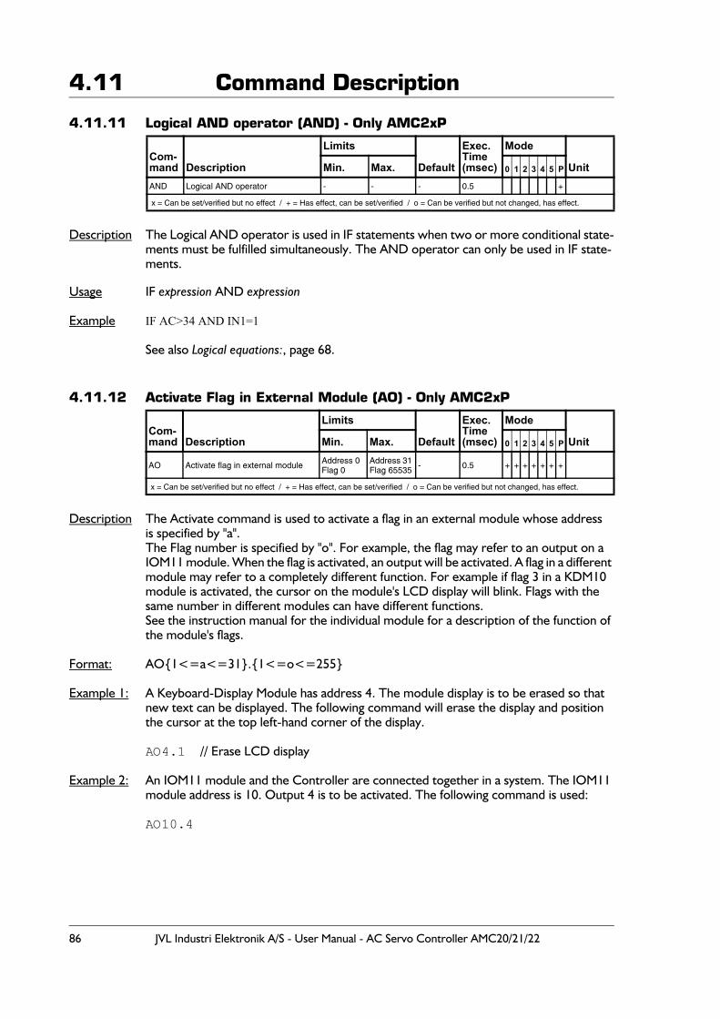
86 JVL Industri Elektronik A/S - User Manual - AC Servo Controller AMC20/21/22
4.11 Command Description
4.11.11 Logical AND operator (AND) - Only AMC2xP
Description The Logical AND operator is used in IF statements when two or more conditional state-ments must be fulfilled simultaneously. The AND operator can only be used in IF state-ments.
Usage IF expression AND expression
Example IF AC>34 AND IN1=1
See also Logical equations:, page 68.
4.11.12 Activate Flag in External Module (AO) - Only AMC2xP
Description The Activate command is used to activate a flag in an external module whose addressis specified by "a".The Flag number is specified by "o". For example, the flag may refer to an output on a IOM11 module. When the flag is activated, an output will be activated. A flag in a different module may refer to a completely different function. For example if flag 3 in a KDM10 module is activated, the cursor on the module's LCD display will blink. Flags with the same number in different modules can have different functions.See the instruction manual for the individual module for a description of the function of the module's flags.
Format: AO{1<=a<=31}.{1<=o<=255}
Example 1: A Keyboard-Display Module has address 4. The module display is to be erased so that new text can be displayed. The following command will erase the display and position the cursor at the top left-hand corner of the display.
AO4.1 // Erase LCD display
Example 2: An IOM11 module and the Controller are connected together in a system. The IOM11 module address is 10. Output 4 is to be activated. The following command is used:
AO10.4
Com-mand Description
Limits
Default
Exec.Time(msec)
Mode
UnitMin. Max. 0 1 2 3 4 5 P
AND Logical AND operator - - - 0.5 +
x = Can be set/verified but no effect / + = Has effect, can be set/verified / o = Can be verified but not changed, has effect.
Com-mand Description
Limits
Default
Exec.Time(msec)
Mode
UnitMin. Max. 0 1 2 3 4 5 P
AO Activate flag in external module Address 0Flag 0
Address 31Flag 65535 - 0.5 + + + + + + +
x = Can be set/verified but no effect / + = Has effect, can be set/verified / o = Can be verified but not changed, has effect.
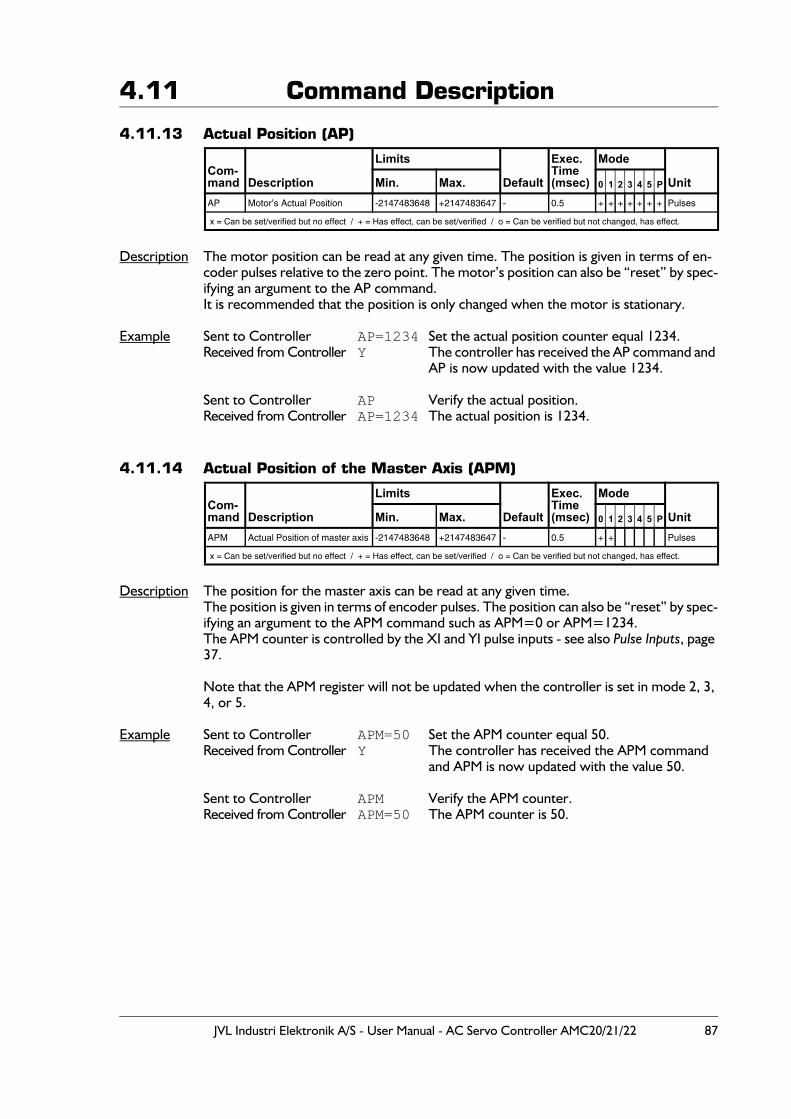
JVL Industri Elektronik A/S - User Manual - AC Servo Controller AMC20/21/22 87
4.11 Command Description
4.11.13 Actual Position (AP)
Description The motor position can be read at any given time. The position is given in terms of en-coder pulses relative to the zero point. The motor’s position can also be “reset” by spec-ifying an argument to the AP command.It is recommended that the position is only changed when the motor is stationary.
Example Sent to Controller AP=1234 Set the actual position counter equal 1234.Received from Controller Y The controller has received the AP command and
AP is now updated with the value 1234.
Sent to Controller AP Verify the actual position.Received from Controller AP=1234 The actual position is 1234.
4.11.14 Actual Position of the Master Axis (APM)
Description The position for the master axis can be read at any given time.The position is given in terms of encoder pulses. The position can also be “reset” by spec-ifying an argument to the APM command such as APM=0 or APM=1234.The APM counter is controlled by the XI and YI pulse inputs - see also Pulse Inputs, page 37.
Note that the APM register will not be updated when the controller is set in mode 2, 3, 4, or 5.
Example Sent to Controller APM=50 Set the APM counter equal 50.Received from Controller Y The controller has received the APM command
and APM is now updated with the value 50.
Sent to Controller APM Verify the APM counter.Received from Controller APM=50 The APM counter is 50.
Com-mand Description
Limits
Default
Exec.Time(msec)
Mode
UnitMin. Max. 0 1 2 3 4 5 P
AP Motor’s Actual Position -2147483648 +2147483647 - 0.5 + + + + + + + Pulses
x = Can be set/verified but no effect / + = Has effect, can be set/verified / o = Can be verified but not changed, has effect.
Com-mand Description
Limits
Default
Exec.Time(msec)
Mode
UnitMin. Max. 0 1 2 3 4 5 P
APM Actual Position of master axis -2147483648 +2147483647 - 0.5 + + Pulses
x = Can be set/verified but no effect / + = Has effect, can be set/verified / o = Can be verified but not changed, has effect.
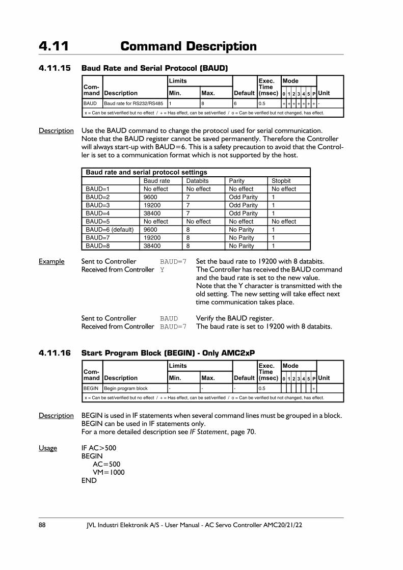
88 JVL Industri Elektronik A/S - User Manual - AC Servo Controller AMC20/21/22
4.11 Command Description
4.11.15 Baud Rate and Serial Protocol (BAUD)
Description Use the BAUD command to change the protocol used for serial communication.Note that the BAUD register cannot be saved permanently. Therefore the Controller will always start-up with BAUD=6. This is a safety precaution to avoid that the Control-ler is set to a communication format which is not supported by the host.
Example Sent to Controller BAUD=7 Set the baud rate to 19200 with 8 databits.Received from Controller Y The Controller has received the BAUD command
and the baud rate is set to the new value.Note that the Y character is transmitted with the old setting. The new setting will take effect next time communication takes place.
Sent to Controller BAUD Verify the BAUD register.Received from Controller BAUD=7 The baud rate is set to 19200 with 8 databits.
4.11.16 Start Program Block (BEGIN) - Only AMC2xP
Description BEGIN is used in IF statements when several command lines must be grouped in a block. BEGIN can be used in IF statements only.For a more detailed description see IF Statement, page 70.
Usage IF AC>500BEGIN
AC=500VM=1000
END
Com-mand Description
Limits
Default
Exec.Time(msec)
Mode
UnitMin. Max. 0 1 2 3 4 5 P
BAUD Baud rate for RS232/RS485 1 8 6 0.5 + + + + + + + -
x = Can be set/verified but no effect / + = Has effect, can be set/verified / o = Can be verified but not changed, has effect.
Baud rate and serial protocol settingsBaud rate Databits Parity Stopbit
BAUD=1 No effect No effect No effect No effectBAUD=2 9600 7 Odd Parity 1BAUD=3 19200 7 Odd Parity 1BAUD=4 38400 7 Odd Parity 1BAUD=5 No effect No effect No effect No effectBAUD=6 (default) 9600 8 No Parity 1BAUD=7 19200 8 No Parity 1BAUD=8 38400 8 No Parity 1
Com-mand Description
Limits
Default
Exec.Time(msec)
Mode
UnitMin. Max. 0 1 2 3 4 5 P
BEGIN Begin program block - - - 0.5 +
x = Can be set/verified but no effect / + = Has effect, can be set/verified / o = Can be verified but not changed, has effect.
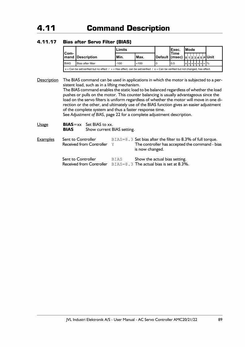
JVL Industri Elektronik A/S - User Manual - AC Servo Controller AMC20/21/22 89
4.11 Command Description
4.11.17 Bias after Servo Filter (BIAS)
Description The BIAS command can be used in applications in which the motor is subjected to a per-sistent load, such as in a lifting mechanism. The BIAS command enables the static load to be balanced regardless of whether the load pushes or pulls on the motor. This counter balancing is usually advantageous since the load on the servo filters is uniform regardless of whether the motor will move in one di-rection or the other, and ultimately use of the BIAS function gives an easier adjustment of the complete system and thus a faster response time.See Adjustment of BIAS, page 22 for a complete adjustment description.
Usage BIAS=xx Set BIAS to xx.BIAS Show current BIAS setting.
Examples Sent to Controller BIAS=8.3 Set bias after the filter to 8.3% of full torque.Received from Controller Y The controller has accepted the command - bias
is now changed.
Sent to Controller BIAS Show the actual bias setting.Received from Controller BIAS=8.3 The actual bias is set at 8.3%.
Com-mand Description
Limits
Default
Exec.Time(msec)
Mode
UnitMin. Max. 0 1 2 3 4 5 P
BIAS Bias after filter -100 +100 0 0.5 x + + + + + + %
x = Can be set/verified but no effect / + = Has effect, can be set/verified / o = Can be verified but not changed, has effect.
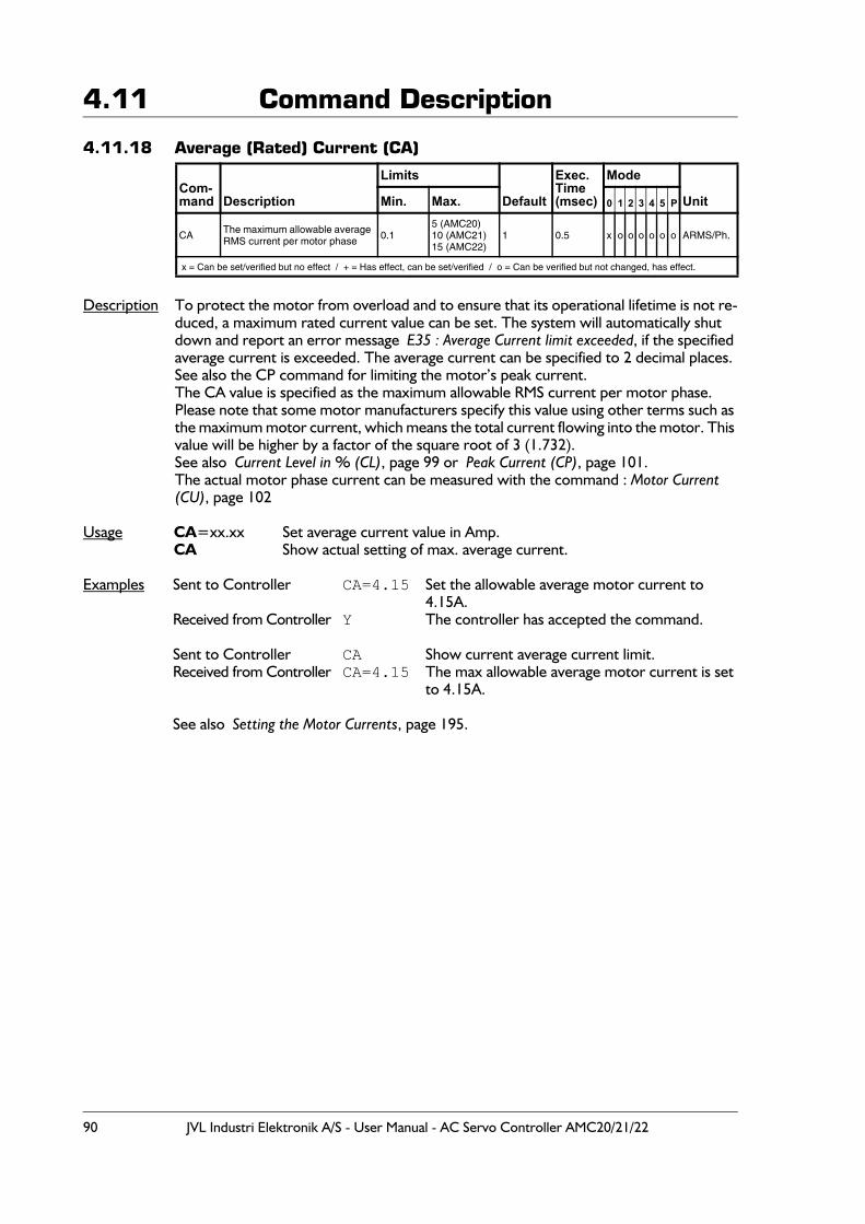
90 JVL Industri Elektronik A/S - User Manual - AC Servo Controller AMC20/21/22
4.11 Command Description
4.11.18 Average (Rated) Current (CA)
Description To protect the motor from overload and to ensure that its operational lifetime is not re-duced, a maximum rated current value can be set. The system will automatically shut down and report an error message E35 : Average Current limit exceeded, if the specified average current is exceeded. The average current can be specified to 2 decimal places.See also the CP command for limiting the motor’s peak current.The CA value is specified as the maximum allowable RMS current per motor phase.Please note that some motor manufacturers specify this value using other terms such as the maximum motor current, which means the total current flowing into the motor. This value will be higher by a factor of the square root of 3 (1.732).See also Current Level in % (CL), page 99 or Peak Current (CP), page 101.The actual motor phase current can be measured with the command : Motor Current (CU), page 102
Usage CA=xx.xx Set average current value in Amp.CA Show actual setting of max. average current.
Examples Sent to Controller CA=4.15 Set the allowable average motor current to 4.15A.
Received from Controller Y The controller has accepted the command.
Sent to Controller CA Show current average current limit.Received from Controller CA=4.15 The max allowable average motor current is set
to 4.15A.
See also Setting the Motor Currents, page 195.
Com-mand Description
Limits
Default
Exec.Time(msec)
Mode
UnitMin. Max. 0 1 2 3 4 5 P
CA The maximum allowable average RMS current per motor phase 0.1
5 (AMC20)10 (AMC21)15 (AMC22)
1 0.5 x o o o o o o ARMS/Ph.
x = Can be set/verified but no effect / + = Has effect, can be set/verified / o = Can be verified but not changed, has effect.
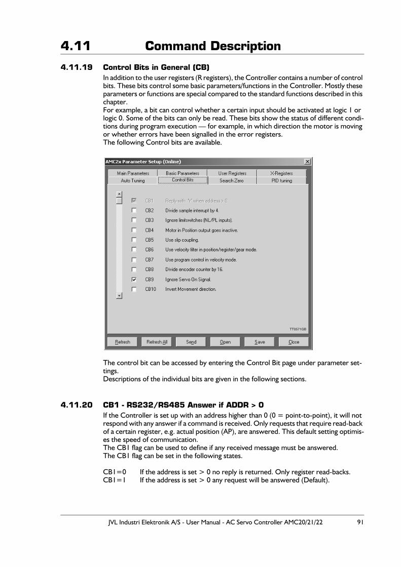
JVL Industri Elektronik A/S - User Manual - AC Servo Controller AMC20/21/22 91
4.11 Command Description
4.11.19 Control Bits in General (CB)In addition to the user registers (R registers), the Controller contains a number of control bits. These bits control some basic parameters/functions in the Controller. Mostly these parameters or functions are special compared to the standard functions described in this chapter.For example, a bit can control whether a certain input should be activated at logic 1 or logic 0. Some of the bits can only be read. These bits show the status of different condi-tions during program execution — for example, in which direction the motor is moving or whether errors have been signalled in the error registers.The following Control bits are available.
The control bit can be accessed by entering the Control Bit page under parameter set-tings.Descriptions of the individual bits are given in the following sections.
4.11.20 CB1 - RS232/RS485 Answer if ADDR > 0If the Controller is set up with an address higher than 0 (0 = point-to-point), it will not respond with any answer if a command is received. Only requests that require read-back of a certain register, e.g. actual position (AP), are answered. This default setting optimis-es the speed of communication.The CB1 flag can be used to define if any received message must be answered.The CB1 flag can be set in the following states.
CB1=0 If the address is set > 0 no reply is returned. Only register read-backs.CB1=1 If the address is set > 0 any request will be answered (Default).
TT0571GB
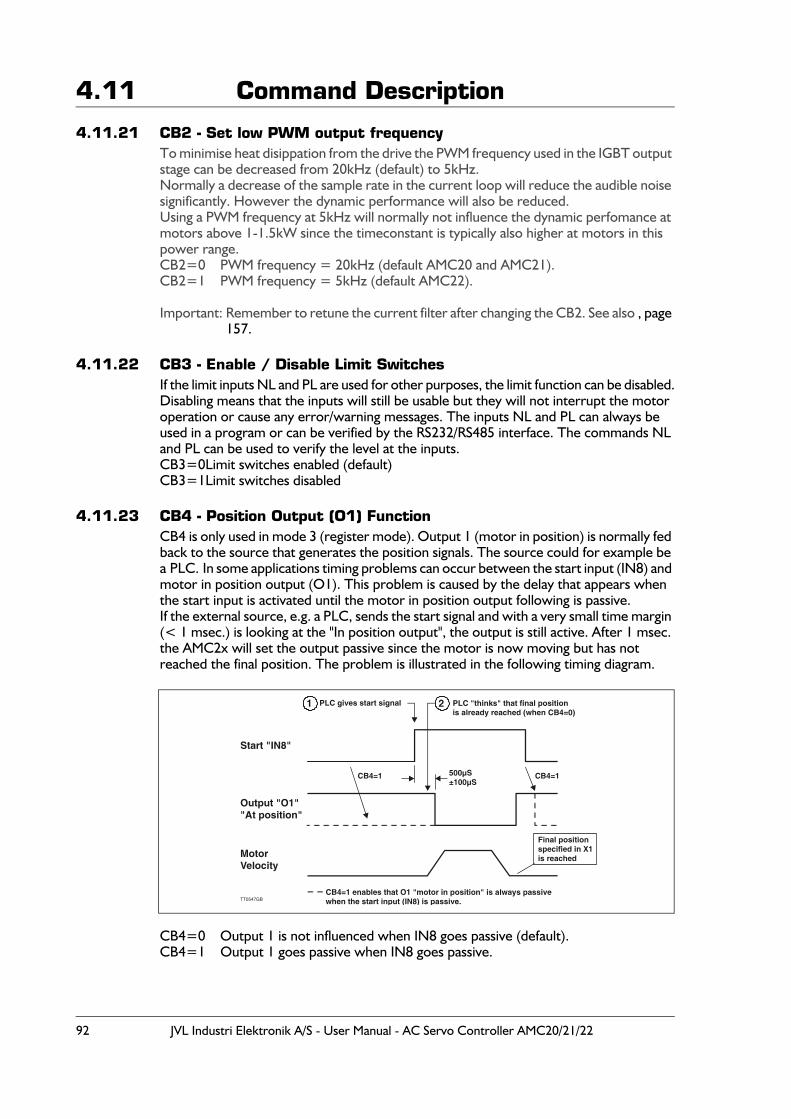
92 JVL Industri Elektronik A/S - User Manual - AC Servo Controller AMC20/21/22
4.11 Command Description
4.11.21 CB2 - Set low PWM output frequencyTo minimise heat disippation from the drive the PWM frequency used in the IGBT output stage can be decreased from 20kHz (default) to 5kHz.Normally a decrease of the sample rate in the current loop will reduce the audible noise significantly. However the dynamic performance will also be reduced.Using a PWM frequency at 5kHz will normally not influence the dynamic perfomance at motors above 1-1.5kW since the timeconstant is typically also higher at motors in this power range.CB2=0 PWM frequency = 20kHz (default AMC20 and AMC21).CB2=1 PWM frequency = 5kHz (default AMC22).
Important: Remember to retune the current filter after changing the CB2. See also , page 157.
4.11.22 CB3 - Enable / Disable Limit SwitchesIf the limit inputs NL and PL are used for other purposes, the limit function can be disabled.Disabling means that the inputs will still be usable but they will not interrupt the motor operation or cause any error/warning messages. The inputs NL and PL can always be used in a program or can be verified by the RS232/RS485 interface. The commands NL and PL can be used to verify the level at the inputs.CB3=0Limit switches enabled (default)CB3=1Limit switches disabled
4.11.23 CB4 - Position Output (O1) FunctionCB4 is only used in mode 3 (register mode). Output 1 (motor in position) is normally fed back to the source that generates the position signals. The source could for example be a PLC. In some applications timing problems can occur between the start input (IN8) and motor in position output (O1). This problem is caused by the delay that appears when the start input is activated until the motor in position output following is passive.If the external source, e.g. a PLC, sends the start signal and with a very small time margin (< 1 msec.) is looking at the "In position output", the output is still active. After 1 msec. the AMC2x will set the output passive since the motor is now moving but has not reached the final position. The problem is illustrated in the following timing diagram.
CB4=0 Output 1 is not influenced when IN8 goes passive (default).CB4=1 Output 1 goes passive when IN8 goes passive.
MotorVelocity
Start "IN8"
Output "O1""At position"
PLC gives start signal PLC "thinks" that final positionis already reached (when CB4=0)
500µS±100µS
Final positionspecified in X1is reached
TT0547GB
1 2
CB4=1CB4=1
CB4=1 enables that O1 "motor in position" is always passivewhen the start input (IN8) is passive.
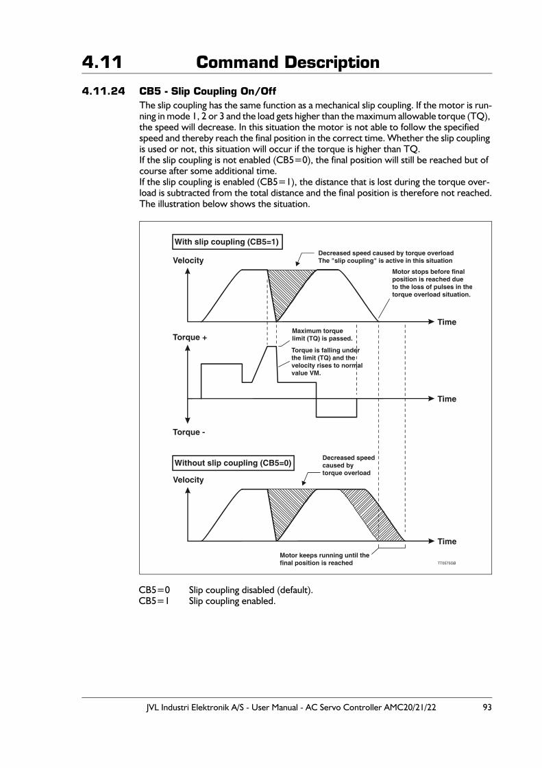
JVL Industri Elektronik A/S - User Manual - AC Servo Controller AMC20/21/22 93
4.11 Command Description
4.11.24 CB5 - Slip Coupling On/OffThe slip coupling has the same function as a mechanical slip coupling. If the motor is run-ning in mode 1, 2 or 3 and the load gets higher than the maximum allowable torque (TQ), the speed will decrease. In this situation the motor is not able to follow the specified speed and thereby reach the final position in the correct time. Whether the slip coupling is used or not, this situation will occur if the torque is higher than TQ.If the slip coupling is not enabled (CB5=0), the final position will still be reached but of course after some additional time.If the slip coupling is enabled (CB5=1), the distance that is lost during the torque over-load is subtracted from the total distance and the final position is therefore not reached.The illustration below shows the situation.
CB5=0 Slip coupling disabled (default).CB5=1 Slip coupling enabled.
Velocity
Velocity
Torque +
Torque -
Decreased speed caused by torque overloadThe "slip coupling" is active in this situation
With slip coupling (CB5=1)
Without slip coupling (CB5=0)Decreased speedcaused bytorque overload
Motor keeps running until thefinal position is reached TT0575GB
Time
Time
Time
Maximum torquelimit (TQ) is passed.
Motor stops before finalposition is reached dueto the loss of pulses in thetorque overload situation.
Torque is falling underthe limit (TQ) and thevelocity rises to normalvalue VM.
94 JVL Industri Elektronik A/S - User Manual - AC Servo Controller AMC20/21/22
4.11 Command Description
4.11.25 CB6 - Filter SelectionUse velocity filter in position/register/gear mode (modes involving absolute positioning).If the mechanical system is elastic, and the position tolerance is low, the velocity filter can be used to ensure a more stable system.
CB6=0 Use position filter (default)CB6=1 Use velocity filter
Please note that the positioning precision is not as good when the velocity filter is used.It is therefore recommended that the following registers are adjusted to a higher value than by using the position filter :FE Following Error - see Following Error (FEM), page 111.PE Maximum Pulse Error - see Maximum Pulse Error (PE), page 136.PES Pulse Error Samples - see Pulse Error Samples (PES), page 137.
4.11.26 CB7 - Mode 4 Source SelectionUse program control in velocity mode (MO=4)Instead of controlling the velocity via the analogue input, AI1, it is possible to control the velocity via VM commands via the controller status window in MotoWare, or via VM commands in a MotoWare program.
CB7=0 Use AI1 (default)CB7=1 Use program control
4.11.27 CB8 - Divide Encoder Input by 16When this control bit is set, the encoder input will be divided by 16. This feature is seldom used but if the Controller is used together with an encoder with a very high resolution, it can be necessary because the encoder input only allows encoder resolutions up to 65535 pulses per electrical cycle. If CB8 is set (CB8=1), the PR value must also be divided by 16. See also Encoder Pulses (PR), page 142.
Example:An encoder rated at 20000 pulses per revolution is used, mounted at a 2-pole motor.20000 pulses per revolution is internally converted to 80000 pulses per revolution since all the transitions in the encoder signals are used. A value of 80000 pulses per revolution is too high (maximum is 65535) and therefore CB8 must be set. The PR register must also be corrected to 1250 (20000/16) instead of 20000.Remember to make a new tuning of the servo filter.
CB8=0 Passive (default).CB8=1 Divide encoder input by 16.
4.11.28 CB9 - Ignore Servo On SignalThe Controller input SON can normally be used for safety. The motor will stay current-less until this input is supplied with an external voltage. CB9 is made to bypass this fea-ture.If CB9 is set to 1, the SON input will be passive (not used) and the motor output will stay fully operational regardless the voltage at the SON input. See also Servo On Input (SON), page 32.
CB9=0 SON input enabled (default).CB9=1 SON input disabled.
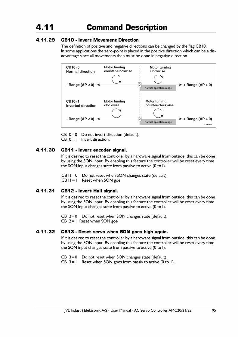
JVL Industri Elektronik A/S - User Manual - AC Servo Controller AMC20/21/22 95
4.11 Command Description
4.11.29 CB10 - Invert Movement DirectionThe definition of positive and negative directions can be changed by the flag CB10.In some applications the zero-point is placed in the positive direction which can be a dis-advantage since all movements then must be done in negative direction.
CB10=0 Do not invert direction (default).CB10=1 Invert direction.
4.11.30 CB11 - Invert encoder signal.If it is desired to reset the controller by a hardware signal from outside, this can be done by using the SON input. By enabling this feature the controller will be reset every time the SON input changes state from passive to active (0 to1).
CB11=0 Do not reset when SON changes state (default).CB11=1 Reset when SON goe
4.11.31 CB12 - Invert Hall signal.If it is desired to reset the controller by a hardware signal from outside, this can be done by using the SON input. By enabling this feature the controller will be reset every time the SON input changes state from passive to active (0 to1).
CB12=0 Do not reset when SON changes state (default).CB12=1 Reset when SON goe
4.11.32 CB13 - Reset servo when SON goes high again.If it is desired to reset the controller by a hardware signal from outside, this can be done by using the SON input. By enabling this feature the controller will be reset every time the SON input changes state from passive to active (0 to1).
CB13=0 Do not reset when SON changes state (default).CB13=1 Reset when SON goes from passiv to active (0 to 1).
+ Range (AP > 0)
+ Range (AP > 0)TT0580GB
- Range (AP < 0)
- Range (AP < 0)
CB10=0 Normal direction
CB10=1 Inverted direction
Motor turningclockwise
Motor turningcounter-clockwise
Motor turningcounter-clockwise
Motor turningclockwise
0
0
Normal operation range
Normal operation range
96 JVL Industri Elektronik A/S - User Manual - AC Servo Controller AMC20/21/22
4.11 Command Description
4.11.33 CB14 - Enable PID FilterThe Controller normally uses a very advanced filter that can be adjusted up to 6 orders.This "standard" filter however involves up to 35 filter constants which are impossible to adjust manually since the behaviour of each filter constant is extremely complex. Only the auto-tuning facility in MotoWare can be used to adjust this filter.As an alternative, a traditional PID filter is available. The PID filter can be adjusted man-ually and is intended to be used in applications where the auto tuning is not possible.See also Adjustment of Servo Regulation, page 18 where a complete description of the filter adjustment is given.
CB14=0 PID filter disabled (default).CB14=1 PID filter enabled.
4.11.34 CB15 - Function of User Output 1 (O1)The user output 1 is set up by default to show when the motor is in position (CB15=1 or CB15=2). This function is only used in mode 2 and 3. Alternatively, the output can be configured to work as a general output with the same function as outputs 2 to 8 (O2-O8), which means that O1 can be controlled through commands send via the RS232 interface or OUT commands implemented in a program (only AMC2xP).In this case the output 1 will not be influenced when the motor is in position or not.
CB15=0 Output 1 can be used for general purposes.CB15=1 Output 1 is used as "in position output". Active high. - Default.CB15=2 Output 1 is used as "in position output". Active low.
4.11.35 CB16 - Function of User Output 2 (O2)By default, the user output 2 is set up to show when the Controller is in fully operational and no fatal errors have occurred (CB16=1 or CB16=2).Alternatively, the output can be configured to work as a general output with the same function as outputs 1 and 3 to 8 (O1, O3-O8), which means that O2 can be controlled through commands send via the RS232 interface or OUT commands implemented in a program (only AMC2xP). In this case the output 2 will not be influenced when the Con-troller is in a passive state or if a fatal error occurs.
CB16=0 Output 2 can be used for general purpose.CB16=1 Output 2 is used as "Controller OK Output". Active high. - Default.CB16=2 Output 2 is used as "Controller OK Output". Active low.
4.11.36 CB17 - Function of User Output 3 (O3)By default, the user output 3 is set up to work as a general output with the same function as outputs 1, 2 and 4 to 8 (O1, O2, O4-O8), which means that O3 can be controlled through commands send via the RS232 interface or OUT commands implemented in a program (only AMC2xP). In this case, output 3 will not be influenced by any other activ-ity in the Controller.Output 3 can however be set up to control a brake at the motor by setting CB17=1 or 2.The output will then be active during normal operation, which means that the brake will be released. If any error occurs or if mode 0 (passive mode) is selected, the output is set passive whereby the brake keeps the motor in a stationary position.
CB17=0 Output 3 can be used for general purpose - Default.CB17=1 Output 3 is used as "Brake Output". Active high.CB17=2 Output 3 is used as "Brake Output". Active low.
JVL Industri Elektronik A/S - User Manual - AC Servo Controller AMC20/21/22 97
4.11 Command Description4.11.37 CB18 - Enable extended gear mode
This bit enables extended gear mode. By extended gear mode means that every pulse received at the pulse inputs is "remembered" also in situations where the maximum mo-tor torque is reached which means that the motor has difficulties by moving in the same speed as the pulses are specifying.
CB18=0 Extended gear mode disabledCB18=1 Extended gear mode enabled (default)
4.11.38 CB19 - Enable passive halt mode.Sometimes it can be desired that the running status register RS is not going to 0 if a Halt or Soft Halt command is executed. By setting CB19 to 1 the RS register will go to 7 in-stead of 0 if a Halt or Soft Halt command is executed. See also Report Motor Status (RS), page 147.
CB19=0 Disable passive halt mode. RS will be set to 0 if a Halt or Soft halt command is executed. (default).
CB19=1 Enable passive halt mode. RS will be set to 7 if a Halt or Softhalt command is executed.
4.11.39 CB20 - Enable direct torque mode.In torque mode the response can be optimized by CB20. By enabling direct torque mode the bandwidth is increased significantly but the limits made by AC (the acceleration pa-rameter) and VM (the topspeed parameter) is completely ignored.
CB20=0 Disable direct torque mode (default).CB20=1 Enable direct torque mode.
4.11.40 CB21 - Use balanced analogue inputs.-CB21=0 Disable (default).CB20=1 Enable.
4.11.41 CB22 - Enable pulse torque mode.-CB22=0 Disable (default).CB22=1 Enable.
4.11.42 CB23 - Invert pulse input direction.-CB23=0 Disable (default).CB23=1 Enable.
98 JVL Industri Elektronik A/S - User Manual - AC Servo Controller AMC20/21/22
4.11 Command Description
4.11.43 CFE Current Following Error in Pulses
Description CFE can be verified to see the static position error in the system. CFE must be seen in combination with FEM which sets the maximum allowable number of pulses in CFE. If this limit is passed, the error message E102 : Encoder error or position error limit exceeded will be given.
Usage CFE Show the actual following error in pulses.
Example Send the command CFE(enter) In the MotoWare online editor.Following is received CFE=15 Which means that the actual static position
error is 15 pulses.
4.11.44 CFNE Current Following Error Nominal in Pulses
Description CFNE can be verified to see the static position error in the system. CFNE must be seen in combination with FNEM which sets the maximum allowable number of pulses in CFNE. If this limit is passed, the error message E102 : Encoder error or position error limit exceeded will be given.
Usage CFNE Show the actual following error in pulses.
Example Send the command CFNE(enter) In the MotoWare online editor.Following is received CFNE=15 Which means that the actual static position
error is 15 pulses.
Com-mand Description
Limits
Default
Exec.Time(msec)
Mode
UnitMin. Max. 0 1 2 3 4 5 P
CFE Show current following error 0 32767 - 0.5 o o o o o o o Pulses
x = Can be set/verified but no effect / + = Has effect, can be set/verified / o = Can be verified but not changed, has effect.
Com-mand Description
Limits
Default
Exec.Time(msec)
Mode
UnitMin. Max. 0 1 2 3 4 5 P
CFNE Show current following error nom. 0 32767 - 0.5 o o o o o o o Pulses
x = Can be set/verified but no effect / + = Has effect, can be set/verified / o = Can be verified but not changed, has effect.
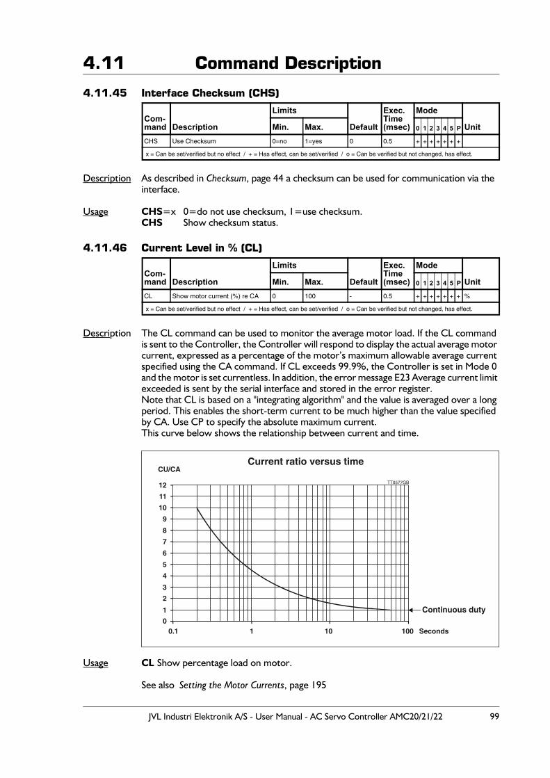
JVL Industri Elektronik A/S - User Manual - AC Servo Controller AMC20/21/22 99
4.11 Command Description
4.11.45 Interface Checksum (CHS)
Description As described in Checksum, page 44 a checksum can be used for communication via the interface.
Usage CHS=x 0=do not use checksum, 1=use checksum.CHS Show checksum status.
4.11.46 Current Level in % (CL)
Description The CL command can be used to monitor the average motor load. If the CL command is sent to the Controller, the Controller will respond to display the actual average motor current, expressed as a percentage of the motor’s maximum allowable average current specified using the CA command. If CL exceeds 99.9%, the Controller is set in Mode 0 and the motor is set currentless. In addition, the error message E23 Average current limit exceeded is sent by the serial interface and stored in the error register.Note that CL is based on a "integrating algorithm" and the value is averaged over a long period. This enables the short-term current to be much higher than the value specified by CA. Use CP to specify the absolute maximum current.This curve below shows the relationship between current and time.
Usage CL Show percentage load on motor.
See also Setting the Motor Currents, page 195
Com-mand Description
Limits
Default
Exec.Time(msec)
Mode
UnitMin. Max. 0 1 2 3 4 5 P
CHS Use Checksum 0=no 1=yes 0 0.5 + + + + + + +
x = Can be set/verified but no effect / + = Has effect, can be set/verified / o = Can be verified but not changed, has effect.
Com-mand Description
Limits
Default
Exec.Time(msec)
Mode
UnitMin. Max. 0 1 2 3 4 5 P
CL Show motor current (%) re CA 0 100 - 0.5 + + + + + + + %
x = Can be set/verified but no effect / + = Has effect, can be set/verified / o = Can be verified but not changed, has effect.
TT0577GB
Continuous duty
Current ratio versus timeCU/CA
12
11
10
9
8
7
6
5
1
00.1 1 10 100 Seconds
2
4
3
100 JVL Industri Elektronik A/S - User Manual - AC Servo Controller AMC20/21/22
4.11 Command Description
4.11.47 Clear Flag in External Module (CO) - Only AMC2xP
Description The Clear command is used to clear a flag in an external module. The number of flags which that can be cleared in different external modules varies, but each module has at least 1 flag. For the KDM10 module (Keyboard-Display Module) for example, the Clear command can be used to clear the LCD display; in the IOM11 module (I/O module) the Clear command can be used to deactivate one of the Module's outputs, etc.
Format: CO {1<=a<=31}.{1<=o<=255}
Example 1: The Controller and a KDM10 module are connected in a system via the JVL Bus inter-face. The address of the Controller is 1 and the KDM10 module address is 3. The Cursor on the KDM10's LCD display is to be switched off. If the cursor is active while text is be-ing printed using the PRINT command, the display may flicker. This is avoided by switch-ing off the cursor as follows:
CO3.3 // Deactivate cursor
Example 2: The Controller and an IOM11 module are connected in a system via the JVL Bus inter-face. The IOM11 module's address is 5. The IOM11's output 7 is to be de-activated. The command is as follows:
CO5.7 // Deactivate output 7 on IOM11 module with address 5.
Com-mand Description
Limits
Default
Exec.Time(msec)
Mode
UnitMin. Max. 0 1 2 3 4 5 P
CO Clear flag in external module Address 0Flag 0
Address 31Flag 65535 - 0.5 + + + + + + +
x = Can be set/verified but no effect / + = Has effect, can be set/verified / o = Can be verified but not changed, has effect.
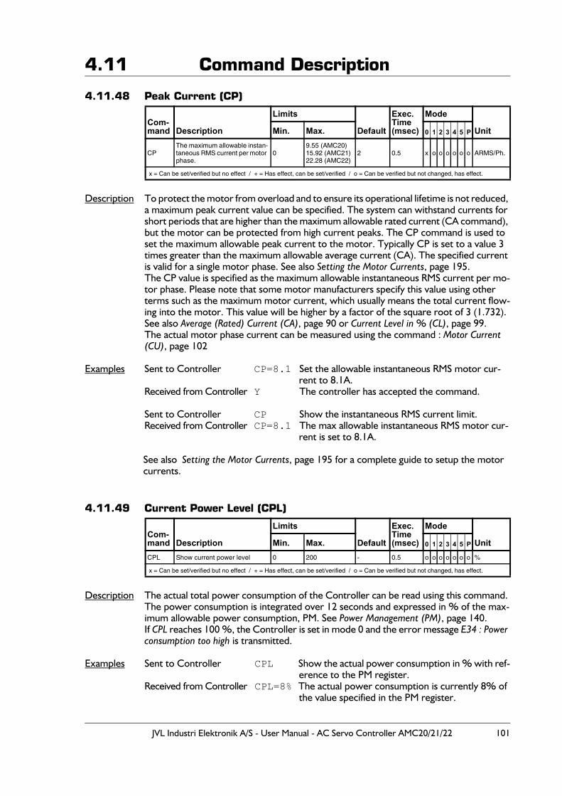
JVL Industri Elektronik A/S - User Manual - AC Servo Controller AMC20/21/22 101
4.11 Command Description
4.11.48 Peak Current (CP)
Description To protect the motor from overload and to ensure its operational lifetime is not reduced, a maximum peak current value can be specified. The system can withstand currents for short periods that are higher than the maximum allowable rated current (CA command), but the motor can be protected from high current peaks. The CP command is used to set the maximum allowable peak current to the motor. Typically CP is set to a value 3 times greater than the maximum allowable average current (CA). The specified current is valid for a single motor phase. See also Setting the Motor Currents, page 195.The CP value is specified as the maximum allowable instantaneous RMS current per mo-tor phase. Please note that some motor manufacturers specify this value using other terms such as the maximum motor current, which usually means the total current flow-ing into the motor. This value will be higher by a factor of the square root of 3 (1.732).See also Average (Rated) Current (CA), page 90 or Current Level in % (CL), page 99.The actual motor phase current can be measured using the command : Motor Current (CU), page 102
Examples Sent to Controller CP=8.1 Set the allowable instantaneous RMS motor cur-rent to 8.1A.
Received from Controller Y The controller has accepted the command.
Sent to Controller CP Show the instantaneous RMS current limit.Received from Controller CP=8.1 The max allowable instantaneous RMS motor cur-
rent is set to 8.1A.
See also Setting the Motor Currents, page 195 for a complete guide to setup the motor currents.
4.11.49 Current Power Level (CPL)
Description The actual total power consumption of the Controller can be read using this command. The power consumption is integrated over 12 seconds and expressed in % of the max-imum allowable power consumption, PM. See Power Management (PM), page 140.If CPL reaches 100 %, the Controller is set in mode 0 and the error message E34 : Power consumption too high is transmitted.
Examples Sent to Controller CPL Show the actual power consumption in % with ref-erence to the PM register.
Received from Controller CPL=8% The actual power consumption is currently 8% of the value specified in the PM register.
Com-mand Description
Limits
Default
Exec.Time(msec)
Mode
UnitMin. Max. 0 1 2 3 4 5 P
CPThe maximum allowable instan-taneous RMS current per motor phase.
09.55 (AMC20)15.92 (AMC21)22.28 (AMC22)
2 0.5 x o o o o o o ARMS/Ph.
x = Can be set/verified but no effect / + = Has effect, can be set/verified / o = Can be verified but not changed, has effect.
Com-mand Description
Limits
Default
Exec.Time(msec)
Mode
UnitMin. Max. 0 1 2 3 4 5 P
CPL Show current power level 0 200 - 0.5 o o o o o o o %
x = Can be set/verified but no effect / + = Has effect, can be set/verified / o = Can be verified but not changed, has effect.
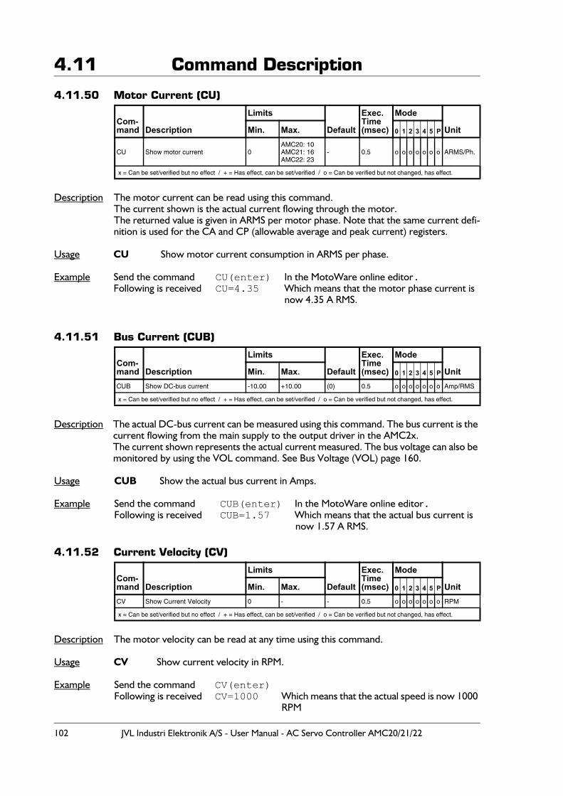
102 JVL Industri Elektronik A/S - User Manual - AC Servo Controller AMC20/21/22
4.11 Command Description
4.11.50 Motor Current (CU)
Description The motor current can be read using this command.The current shown is the actual current flowing through the motor.The returned value is given in ARMS per motor phase. Note that the same current defi-nition is used for the CA and CP (allowable average and peak current) registers.
Usage CU Show motor current consumption in ARMS per phase.
Example Send the command CU(enter) In the MotoWare online editor.Following is received CU=4.35 Which means that the motor phase current is
now 4.35 A RMS.
4.11.51 Bus Current (CUB)
Description The actual DC-bus current can be measured using this command. The bus current is the current flowing from the main supply to the output driver in the AMC2x.The current shown represents the actual current measured. The bus voltage can also be monitored by using the VOL command. See Bus Voltage (VOL) page 160.
Usage CUB Show the actual bus current in Amps.
Example Send the command CUB(enter) In the MotoWare online editor.Following is received CUB=1.57 Which means that the actual bus current is
now 1.57 A RMS.
4.11.52 Current Velocity (CV)
Description The motor velocity can be read at any time using this command.
Usage CV Show current velocity in RPM.
Example Send the command CV(enter)Following is received CV=1000 Which means that the actual speed is now 1000
RPM
Com-mand Description
Limits
Default
Exec.Time(msec)
Mode
UnitMin. Max. 0 1 2 3 4 5 P
CU Show motor current 0AMC20: 10AMC21: 16AMC22: 23
- 0.5 o o o o o o o ARMS/Ph.
x = Can be set/verified but no effect / + = Has effect, can be set/verified / o = Can be verified but not changed, has effect.
Com-mand Description
Limits
Default
Exec.Time(msec)
Mode
UnitMin. Max. 0 1 2 3 4 5 P
CUB Show DC-bus current -10.00 +10.00 (0) 0.5 o o o o o o o Amp/RMS
x = Can be set/verified but no effect / + = Has effect, can be set/verified / o = Can be verified but not changed, has effect.
Com-mand Description
Limits
Default
Exec.Time(msec)
Mode
UnitMin. Max. 0 1 2 3 4 5 P
CV Show Current Velocity 0 - - 0.5 o o o o o o o RPM
x = Can be set/verified but no effect / + = Has effect, can be set/verified / o = Can be verified but not changed, has effect.
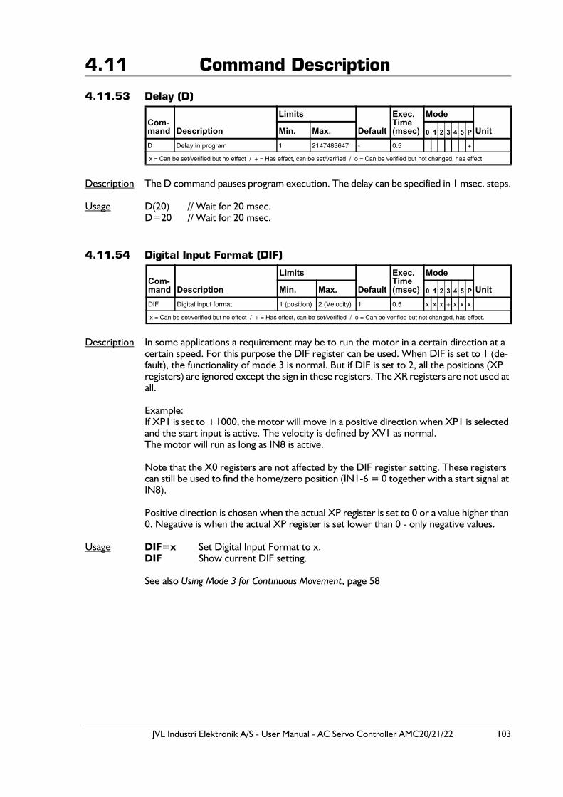
JVL Industri Elektronik A/S - User Manual - AC Servo Controller AMC20/21/22 103
4.11 Command Description
4.11.53 Delay (D)
Description The D command pauses program execution. The delay can be specified in 1 msec. steps.
Usage D(20) // Wait for 20 msec.D=20 // Wait for 20 msec.
4.11.54 Digital Input Format (DIF)
Description In some applications a requirement may be to run the motor in a certain direction at a certain speed. For this purpose the DIF register can be used. When DIF is set to 1 (de-fault), the functionality of mode 3 is normal. But if DIF is set to 2, all the positions (XP registers) are ignored except the sign in these registers. The XR registers are not used at all.
Example:If XP1 is set to +1000, the motor will move in a positive direction when XP1 is selected and the start input is active. The velocity is defined by XV1 as normal.The motor will run as long as IN8 is active.
Note that the X0 registers are not affected by the DIF register setting. These registers can still be used to find the home/zero position (IN1-6 = 0 together with a start signal at IN8).
Positive direction is chosen when the actual XP register is set to 0 or a value higher than 0. Negative is when the actual XP register is set lower than 0 - only negative values.
Usage DIF=x Set Digital Input Format to x.DIF Show current DIF setting.
See also Using Mode 3 for Continuous Movement, page 58
Com-mand Description
Limits
Default
Exec.Time(msec)
Mode
UnitMin. Max. 0 1 2 3 4 5 P
D Delay in program 1 2147483647 - 0.5 +
x = Can be set/verified but no effect / + = Has effect, can be set/verified / o = Can be verified but not changed, has effect.
Com-mand Description
Limits
Default
Exec.Time(msec)
Mode
UnitMin. Max. 0 1 2 3 4 5 P
DIF Digital input format 1 (position) 2 (Velocity) 1 0.5 x x x + x x x
x = Can be set/verified but no effect / + = Has effect, can be set/verified / o = Can be verified but not changed, has effect.
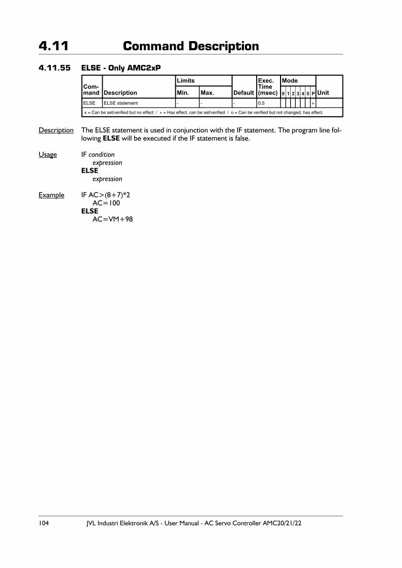
104 JVL Industri Elektronik A/S - User Manual - AC Servo Controller AMC20/21/22
4.11 Command Description
4.11.55 ELSE - Only AMC2xP
Description The ELSE statement is used in conjunction with the IF statement. The program line fol-lowing ELSE will be executed if the IF statement is false.
Usage IF conditionexpression
ELSEexpression
Example IF AC>(8+7)*2AC=100
ELSEAC=VM+98
Com-mand Description
Limits
Default
Exec.Time(msec)
Mode
UnitMin. Max. 0 1 2 3 4 5 P
ELSE ELSE statement - - - 0.5 +
x = Can be set/verified but no effect / + = Has effect, can be set/verified / o = Can be verified but not changed, has effect.
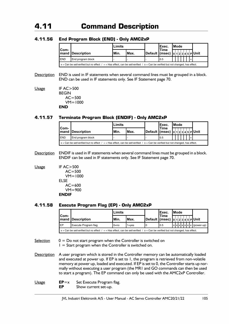
JVL Industri Elektronik A/S - User Manual - AC Servo Controller AMC20/21/22 105
4.11 Command Description
4.11.56 End Program Block (END) - Only AMC2xP
Description END is used in IF statements when several command lines must be grouped in a block. END can be used in IF statements only. See IF Statement page 70.
Usage IF AC>500BEGIN
AC=500VM=1000
END
4.11.57 Terminate Program Block (ENDIF) - Only AMC2xP
Description ENDIF is used in IF statements when several command lines must be grouped in a block. ENDIF can be used in IF statements only. See IF Statement page 70.
Usage IF AC>500AC=500VM=1000
ELSEAC=600VM=900
ENDIF
4.11.58 Execute Program Flag (EP) - Only AMC2xP
Selection 0 = Do not start program when the Controller is switched on1 = Start program when the Controller is switched on.
Description A user program which is stored in the Controller memory can be automatically loaded and executed at power up. If EP is set to 1, the program is retrieved from non-volatile memory at power up, loaded and executed. If EP is set to 0, the Controller starts up nor-mally without executing a user program (the MR1 and GO commands can then be used to start a program). The EP command can only be used with the AMC2xP Controller.
Usage EP=x Set Execute Program flag.EP Show current set-up.
Com-mand Description
Limits
Default
Exec.Time(msec)
Mode
UnitMin. Max. 0 1 2 3 4 5 P
END End program block - - - 0.5 +
x = Can be set/verified but no effect / + = Has effect, can be set/verified / o = Can be verified but not changed, has effect.
Com-mand Description
Limits
Default
Exec.Time(msec)
Mode
UnitMin. Max. 0 1 2 3 4 5 P
END End program block - - - 0.5 +
x = Can be set/verified but no effect / + = Has effect, can be set/verified / o = Can be verified but not changed, has effect.
Com-mand Description
Limits
Default
Exec.Time(msec)
Mode
UnitMin. Max. 0 1 2 3 4 5 P
EP Execute Program flag 0=no 1=yes 0 0.5 x x x x x x x (power-up)
x = Can be set/verified but no effect / + = Has effect, can be set/verified / o = Can be verified but not changed, has effect.
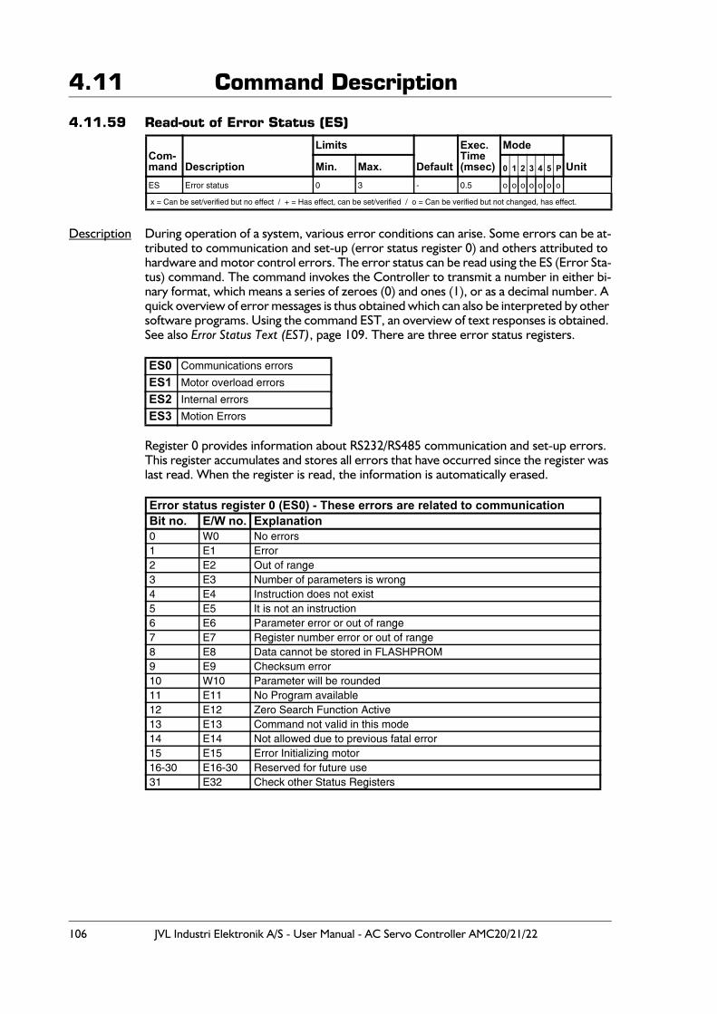
106 JVL Industri Elektronik A/S - User Manual - AC Servo Controller AMC20/21/22
4.11 Command Description
4.11.59 Read-out of Error Status (ES)
Description During operation of a system, various error conditions can arise. Some errors can be at-tributed to communication and set-up (error status register 0) and others attributed to hardware and motor control errors. The error status can be read using the ES (Error Sta-tus) command. The command invokes the Controller to transmit a number in either bi-nary format, which means a series of zeroes (0) and ones (1), or as a decimal number. A quick overview of error messages is thus obtained which can also be interpreted by other software programs. Using the command EST, an overview of text responses is obtained. See also Error Status Text (EST), page 109. There are three error status registers.
Register 0 provides information about RS232/RS485 communication and set-up errors. This register accumulates and stores all errors that have occurred since the register was last read. When the register is read, the information is automatically erased.
Com-mand Description
Limits
Default
Exec.Time(msec)
Mode
UnitMin. Max. 0 1 2 3 4 5 P
ES Error status 0 3 - 0.5 o o o o o o o
x = Can be set/verified but no effect / + = Has effect, can be set/verified / o = Can be verified but not changed, has effect.
ES0 Communications errors
ES1 Motor overload errors
ES2 Internal errors
ES3 Motion Errors
Error status register 0 (ES0) - These errors are related to communicationBit no. E/W no. Explanation0 W0 No errors1 E1 Error2 E2 Out of range3 E3 Number of parameters is wrong4 E4 Instruction does not exist5 E5 It is not an instruction6 E6 Parameter error or out of range7 E7 Register number error or out of range8 E8 Data cannot be stored in FLASHPROM9 E9 Checksum error10 W10 Parameter will be rounded11 E11 No Program available12 E12 Zero Search Function Active13 E13 Command not valid in this mode14 E14 Not allowed due to previous fatal error15 E15 Error Initializing motor16-30 E16-30 Reserved for future use31 E32 Check other Status Registers
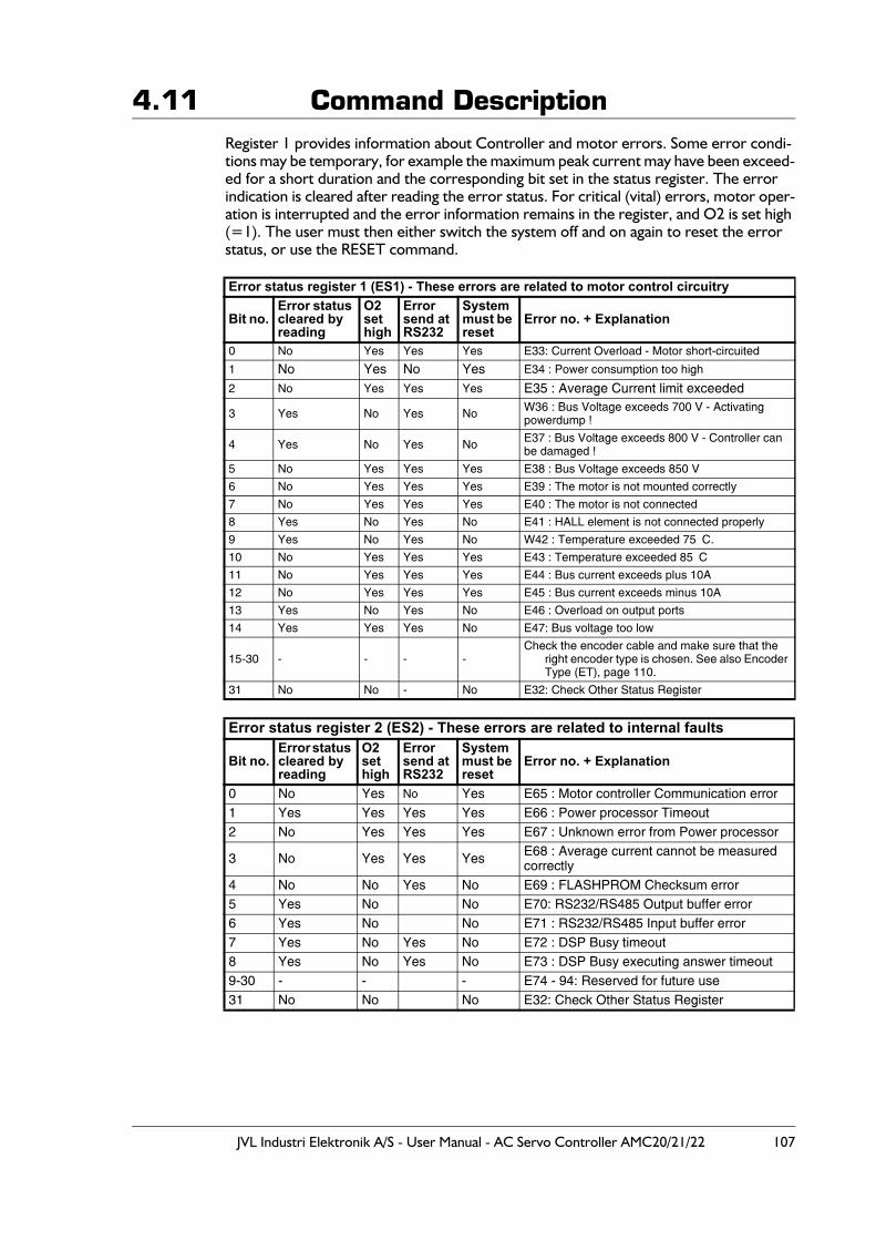
JVL Industri Elektronik A/S - User Manual - AC Servo Controller AMC20/21/22 107
4.11 Command DescriptionRegister 1 provides information about Controller and motor errors. Some error condi-tions may be temporary, for example the maximum peak current may have been exceed-ed for a short duration and the corresponding bit set in the status register. The error indication is cleared after reading the error status. For critical (vital) errors, motor oper-ation is interrupted and the error information remains in the register, and O2 is set high (=1). The user must then either switch the system off and on again to reset the error status, or use the RESET command.
Error status register 1 (ES1) - These errors are related to motor control circuitry
Bit no.Error status cleared by reading
O2sethigh
Error send at RS232
Systemmust be reset
Error no. + Explanation
0 No Yes Yes Yes E33: Current Overload - Motor short-circuited
1 No Yes No Yes E34 : Power consumption too high
2 No Yes Yes Yes E35 : Average Current limit exceeded
3 Yes No Yes No W36 : Bus Voltage exceeds 700 V - Activating powerdump !
4 Yes No Yes No E37 : Bus Voltage exceeds 800 V - Controller can be damaged !
5 No Yes Yes Yes E38 : Bus Voltage exceeds 850 V
6 No Yes Yes Yes E39 : The motor is not mounted correctly
7 No Yes Yes Yes E40 : The motor is not connected
8 Yes No Yes No E41 : HALL element is not connected properly
9 Yes No Yes No W42 : Temperature exceeded 75�C.
10 No Yes Yes Yes E43 : Temperature exceeded 85�C
11 No Yes Yes Yes E44 : Bus current exceeds plus 10A
12 No Yes Yes Yes E45 : Bus current exceeds minus 10A
13 Yes No Yes No E46 : Overload on output ports
14 Yes Yes Yes No E47: Bus voltage too low
15-30 - - - -Check the encoder cable and make sure that the
right encoder type is chosen. See also Encoder Type (ET), page 110.
31 No No - No E32: Check Other Status Register
Error status register 2 (ES2) - These errors are related to internal faults
Bit no.Error status cleared by reading
O2sethigh
Error send at RS232
Systemmust be reset
Error no. + Explanation
0 No Yes No Yes E65 : Motor controller Communication error1 Yes Yes Yes Yes E66 : Power processor Timeout2 No Yes Yes Yes E67 : Unknown error from Power processor
3 No Yes Yes Yes E68 : Average current cannot be measured correctly
4 No No Yes No E69 : FLASHPROM Checksum error5 Yes No No E70: RS232/RS485 Output buffer error6 Yes No No E71 : RS232/RS485 Input buffer error7 Yes No Yes No E72 : DSP Busy timeout8 Yes No Yes No E73 : DSP Busy executing answer timeout9-30 - - - E74 - 94: Reserved for future use31 No No No E32: Check Other Status Register
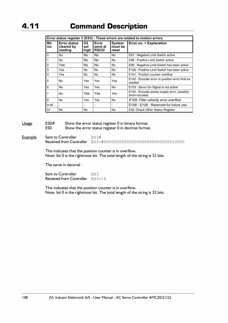
108 JVL Industri Elektronik A/S - User Manual - AC Servo Controller AMC20/21/22
4.11 Command Description
Usage ES0# Show the error status register 0 in binary format.ES0 Show the error status register 0 in decimal format.
Example Sent to Controller ES3#Received from Controller ES3=#00000000000000000000000000010000
This indicates that the position counter is in overflow.Note: bit 0 is the rightmost bit. The total length of the string is 32 bits.
The same in decimal :
Sent to Controller ES3Received from Controller ES3=16
This indicates that the position counter is in overflow.Note: bit 0 is the rightmost bit. The total length of the string is 32 bits.
Error status register 3 (ES3) - These errors are related to motion errorsBit no.
Error status cleared by reading
O2sethigh
Error send at RS232
Systemmust be reset
Error no. + Explanation
0 No No No No E97 : Negative Limit Switch active
1 No No No No E98 : Positive Limit Switch active
2 Yes No No No E99 : Negative Limit Switch has been active
3 Yes No No No E100 : Positive Limit Switch has been active
4 Yes No No No E101 : Position counter overflow
5 No Yes Yes Yes E102 : Encoder error or position error limit ex-ceeded
6 No Yes Yes No E103 : Servo On Signal is not active
7 No Yes Yes Yes E104 : Encoder power supply error, possibly short-circuited.
8 No Yes Yes No E105: Filter velocity error overflow9-30 - - - - E106 - E126 : Reserved for future use31 No No No E32: Check Other Status Register
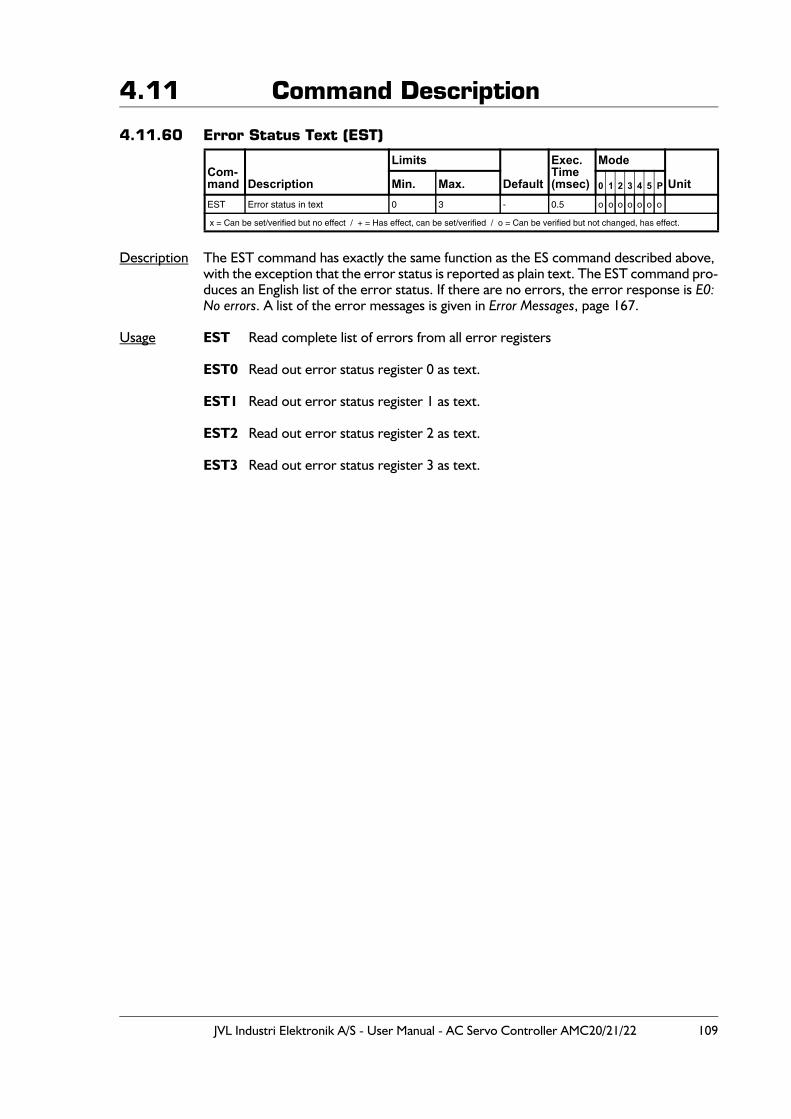
JVL Industri Elektronik A/S - User Manual - AC Servo Controller AMC20/21/22 109
4.11 Command Description 4.11.60 Error Status Text (EST)
Description The EST command has exactly the same function as the ES command described above, with the exception that the error status is reported as plain text. The EST command pro-duces an English list of the error status. If there are no errors, the error response is E0: No errors. A list of the error messages is given in Error Messages, page 167.
Usage EST Read complete list of errors from all error registers
EST0 Read out error status register 0 as text.
EST1 Read out error status register 1 as text.
EST2 Read out error status register 2 as text.
EST3 Read out error status register 3 as text.
Com-mand Description
Limits
Default
Exec.Time(msec)
Mode
UnitMin. Max. 0 1 2 3 4 5 P
EST Error status in text 0 3 - 0.5 o o o o o o o
x = Can be set/verified but no effect / + = Has effect, can be set/verified / o = Can be verified but not changed, has effect.
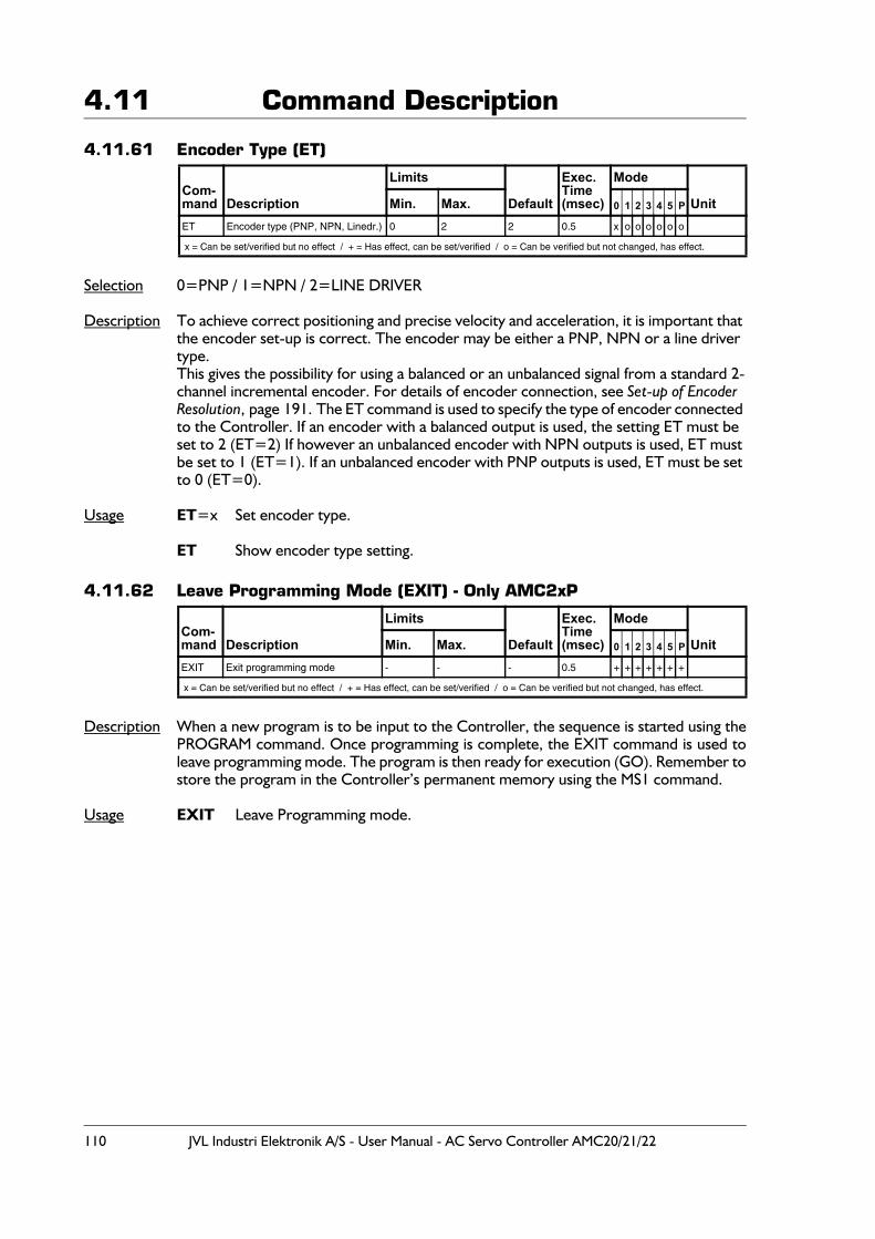
110 JVL Industri Elektronik A/S - User Manual - AC Servo Controller AMC20/21/22
4.11 Command Description
4.11.61 Encoder Type (ET)
Selection 0=PNP / 1=NPN / 2=LINE DRIVER
Description To achieve correct positioning and precise velocity and acceleration, it is important that the encoder set-up is correct. The encoder may be either a PNP, NPN or a line driver type.This gives the possibility for using a balanced or an unbalanced signal from a standard 2-channel incremental encoder. For details of encoder connection, see Set-up of Encoder Resolution, page 191. The ET command is used to specify the type of encoder connected to the Controller. If an encoder with a balanced output is used, the setting ET must be set to 2 (ET=2) If however an unbalanced encoder with NPN outputs is used, ET must be set to 1 (ET=1). If an unbalanced encoder with PNP outputs is used, ET must be set to 0 (ET=0).
Usage ET=x Set encoder type.
ET Show encoder type setting.
4.11.62 Leave Programming Mode (EXIT) - Only AMC2xP
Description When a new program is to be input to the Controller, the sequence is started using thePROGRAM command. Once programming is complete, the EXIT command is used toleave programming mode. The program is then ready for execution (GO). Remember tostore the program in the Controller’s permanent memory using the MS1 command.
Usage EXIT Leave Programming mode.
Com-mand Description
Limits
Default
Exec.Time(msec)
Mode
UnitMin. Max. 0 1 2 3 4 5 P
ET Encoder type (PNP, NPN, Linedr.) 0 2 2 0.5 x o o o o o o
x = Can be set/verified but no effect / + = Has effect, can be set/verified / o = Can be verified but not changed, has effect.
Com-mand Description
Limits
Default
Exec.Time(msec)
Mode
UnitMin. Max. 0 1 2 3 4 5 P
EXIT Exit programming mode - - - 0.5 + + + + + + +
x = Can be set/verified but no effect / + = Has effect, can be set/verified / o = Can be verified but not changed, has effect.
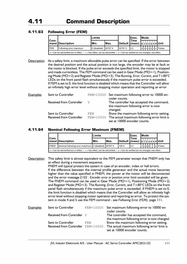
JVL Industri Elektronik A/S - User Manual - AC Servo Controller AMC20/21/22 111
4.11 Command Description
4.11.63 Following Error (FEM)
Description As a safety limit, a maximum allowable pulse error can be specified. If the error betweenthe desired position and the actual position is too large, the encoder may be at fault orthe motor is blocked. If the pulse error exceeds the specified limit, the motor is stoppedand made currentless. The FEM command can be used in Gear Mode (MO=1), Position-ing Mode (MO=2) and Register Mode (MO=3). The Running, Error, Current, and T>80°CLEDs on the front panel flash simultaneously if the maximum pulse error is exceeded.If FEM is set to 0, the limit function is disabled which means that the Controller will allow an infinitely high error level without stopping motor operation and reporting an error
Examples Sent to Controller FEM=10000 Set maximum following error to 10000 en-coder counts.
Received from Controller Y The controller has accepted the command, the maximum following error is now changed.
Sent to Controller FEM Show the maximum following error setting.Received from Controller FEM=10000 The actual maximum following error limit is
set at 10000 encoder counts.
4.11.64 Nominal Following Error Maximum (FNEM)
Description This safety limit is almost equivalent to the FEM parameter except that FNEM only hasan effect during a movement sequence.FNEM will typical protect the system in case of an encoder, index or hall errors.If the difference between the internal profile generator and the actual move becomeshigher than the value specified in FNEM, the power at the motor will be disconnectedand the error message E102 : Encoder error or position error limit exceeded will be given.The FNEM command can be used in Gear Mode (MO=1), Positioning Mode (MO=2)and Register Mode (MO=3). The Running, Error, Current, and T>80°C LEDs on the frontpanel flash simultaneously if the maximum pulse error is exceeded. If FNEM is set to 0,the limit function is disabled which means that the Controller will allow an infinitely higherror level without stopping motor operation and reporting an error. To protect the sys-tem in mode 4 and 5 use the FEM command - see Following Error (FEM), page 111.
Examples Sent to Controller FEM=10000 Set maximum following error to 10000 en-coder counts.
Received from Controller Y The controller has accepted the command, the maximum following error is now changed.
Sent to Controller FEM Show the maximum following error setting.Received from Controller FEM=10000 The actual maximum following error limit is
set at 10000 encoder counts.
Com-mand Description
Limits
Default
Exec.Time(msec)
Mode
UnitMin. Max. 0 1 2 3 4 5 P
FEM Following error maximum 0 (disabled) 32767 # 32767 # 0.5 x + + + + + + Pulses
x = Can be set/verified but no effect / + = Has effect, can be set/verified / o = Can be verified but not changed, has effect.
Com-mand Description
Limits
Default
Exec.Time(msec)
Mode
UnitMin. Max. 0 1 2 3 4 5 P
FNEM Nominal following error maximum 0 (disabled) 32767 # 100 # 0.5 + + x x x Pulses
x = Can be set/verified but no effect / + = Has effect, can be set/verified / o = Can be verified but not changed, has effect.
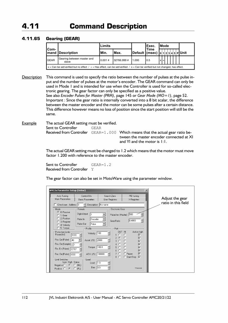
112 JVL Industri Elektronik A/S - User Manual - AC Servo Controller AMC20/21/22
4.11 Command Description
4.11.65 Gearing (GEAR)
Description This command is used to specify the ratio between the number of pulses at the pulse in-put and the number of pulses at the motor’s encoder. The GEAR command can only be used in Mode 1 and is intended for use when the Controller is used for so-called elec-tronic gearing. The gear factor can only be specified as a positive value.See also Encoder Pulses for Master (PRM), page 145 or Gear Mode (MO=1), page 52.Important : Since the gear ratio is internally converted into a 8 bit scalar, the difference between the master encoder and the motor can be some pulses after a certain distance. This difference however means no loss of position since the start position will still be the same.
Example The actual GEAR setting must be verified. Sent to Controller GEAR
Received from Controller GEAR=1.000 Which means that the actual gear ratio be-tween the master encoder connected at XI and YI and the motor is 1:1.
The actual GEAR setting must be changed to 1.2 which means that the motor must move factor 1.200 with reference to the master encoder.
Sent to Controller GEAR=1.2Received from Controller Y
The gear factor can also be set in MotoWare using the parameter window.
Com-mand Description
Limits
Default
Exec.Time(msec)
Mode
UnitMin. Max. 0 1 2 3 4 5 P
GEAR Gearing between master and slave 0.001 # 32766.999 # 1.000 0.5 x +
x = Can be set/verified but no effect / + = Has effect, can be set/verified / o = Can be verified but not changed, has effect.
TT9024GB
Adjust the gearratio in this field
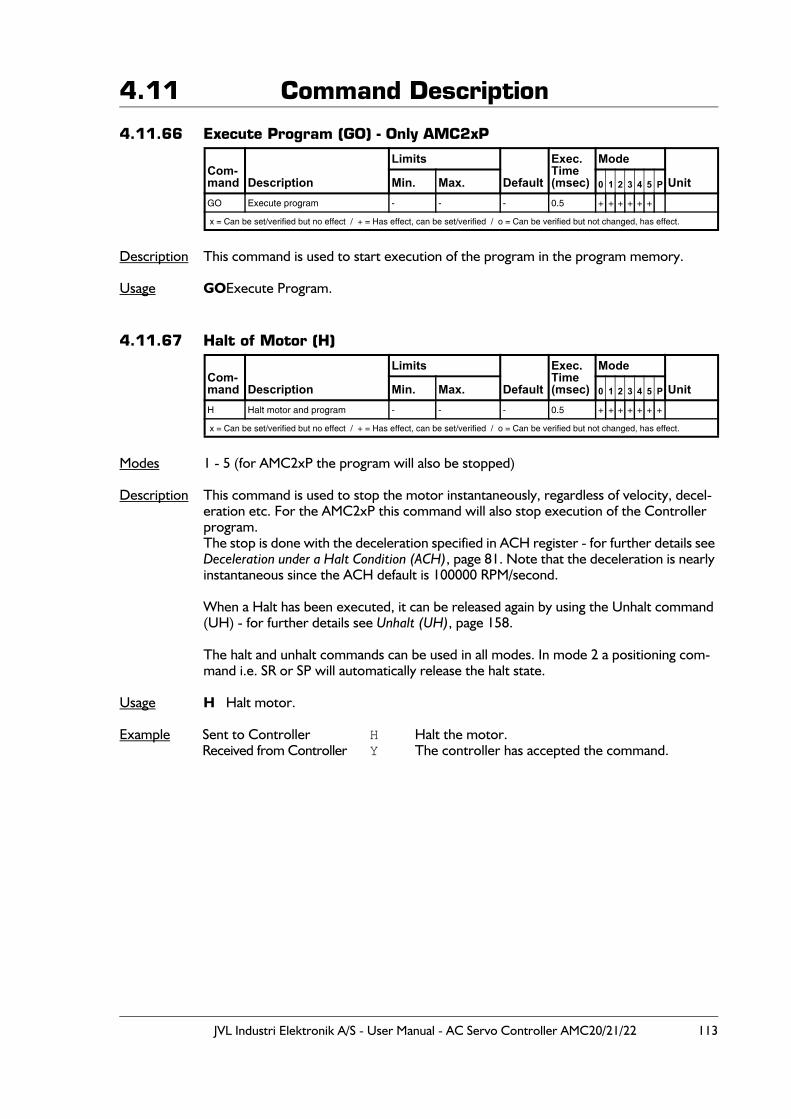
JVL Industri Elektronik A/S - User Manual - AC Servo Controller AMC20/21/22 113
4.11 Command Description
4.11.66 Execute Program (GO) - Only AMC2xP
Description This command is used to start execution of the program in the program memory.
Usage GOExecute Program.
4.11.67 Halt of Motor (H)
Modes 1 - 5 (for AMC2xP the program will also be stopped)
Description This command is used to stop the motor instantaneously, regardless of velocity, decel-eration etc. For the AMC2xP this command will also stop execution of the Controller program.The stop is done with the deceleration specified in ACH register - for further details see Deceleration under a Halt Condition (ACH), page 81. Note that the deceleration is nearly instantaneous since the ACH default is 100000 RPM/second.
When a Halt has been executed, it can be released again by using the Unhalt command (UH) - for further details see Unhalt (UH), page 158.
The halt and unhalt commands can be used in all modes. In mode 2 a positioning com-mand i.e. SR or SP will automatically release the halt state.
Usage H Halt motor.
Example Sent to Controller H Halt the motor.Received from Controller Y The controller has accepted the command.
Com-mand Description
Limits
Default
Exec.Time(msec)
Mode
UnitMin. Max. 0 1 2 3 4 5 P
GO Execute program - - - 0.5 + + + + + +
x = Can be set/verified but no effect / + = Has effect, can be set/verified / o = Can be verified but not changed, has effect.
Com-mand Description
Limits
Default
Exec.Time(msec)
Mode
UnitMin. Max. 0 1 2 3 4 5 P
H Halt motor and program - - - 0.5 + + + + + + +
x = Can be set/verified but no effect / + = Has effect, can be set/verified / o = Can be verified but not changed, has effect.
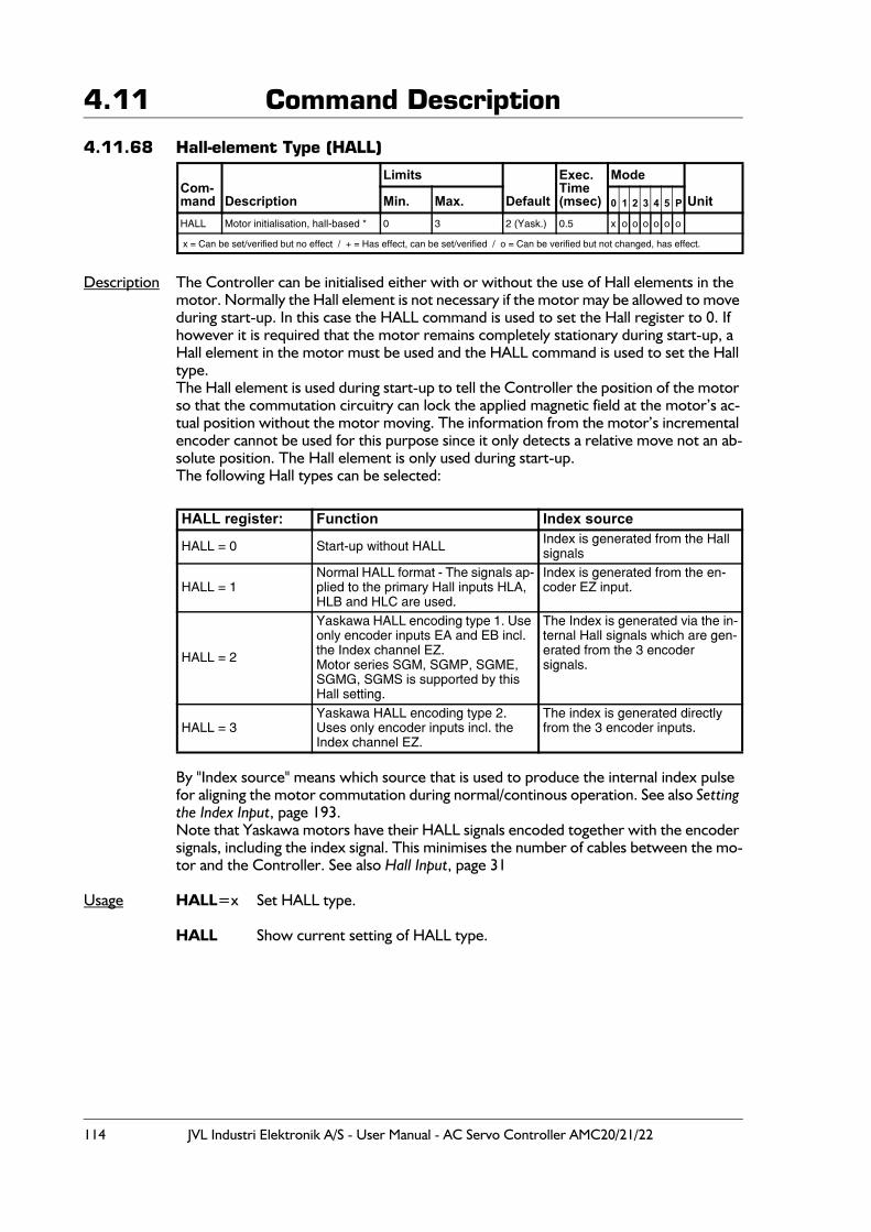
114 JVL Industri Elektronik A/S - User Manual - AC Servo Controller AMC20/21/22
4.11 Command Description
4.11.68 Hall-element Type (HALL)
Description The Controller can be initialised either with or without the use of Hall elements in the motor. Normally the Hall element is not necessary if the motor may be allowed to move during start-up. In this case the HALL command is used to set the Hall register to 0. If however it is required that the motor remains completely stationary during start-up, a Hall element in the motor must be used and the HALL command is used to set the Hall type.The Hall element is used during start-up to tell the Controller the position of the motor so that the commutation circuitry can lock the applied magnetic field at the motor’s ac-tual position without the motor moving. The information from the motor’s incremental encoder cannot be used for this purpose since it only detects a relative move not an ab-solute position. The Hall element is only used during start-up.The following Hall types can be selected:
By "Index source" means which source that is used to produce the internal index pulse for aligning the motor commutation during normal/continous operation. See also Setting the Index Input, page 193. Note that Yaskawa motors have their HALL signals encoded together with the encoder signals, including the index signal. This minimises the number of cables between the mo-tor and the Controller. See also Hall Input, page 31
Usage HALL=x Set HALL type.
HALL Show current setting of HALL type.
Com-mand Description
Limits
Default
Exec.Time(msec)
Mode
UnitMin. Max. 0 1 2 3 4 5 P
HALL Motor initialisation, hall-based * 0 3 2 (Yask.) 0.5 x o o o o o o
x = Can be set/verified but no effect / + = Has effect, can be set/verified / o = Can be verified but not changed, has effect.
HALL register: Function Index source
HALL = 0 Start-up without HALL Index is generated from the Hall signals
HALL = 1Normal HALL format - The signals ap-plied to the primary Hall inputs HLA, HLB and HLC are used.
Index is generated from the en-coder EZ input.
HALL = 2
Yaskawa HALL encoding type 1. Use only encoder inputs EA and EB incl. the Index channel EZ.Motor series SGM, SGMP, SGME, SGMG, SGMS is supported by this Hall setting.
The Index is generated via the in-ternal Hall signals which are gen-erated from the 3 encoder signals.
HALL = 3Yaskawa HALL encoding type 2.Uses only encoder inputs incl. the Index channel EZ.
The index is generated directly from the 3 encoder inputs.
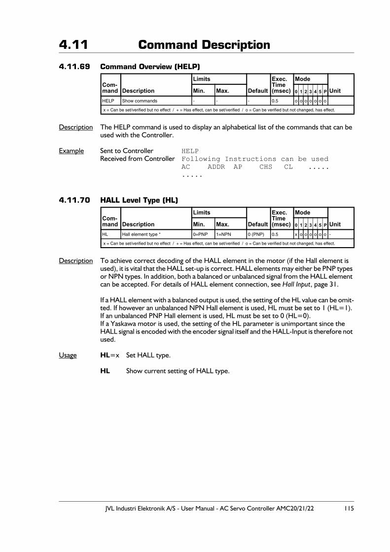
JVL Industri Elektronik A/S - User Manual - AC Servo Controller AMC20/21/22 115
4.11 Command Description
4.11.69 Command Overview (HELP)
Description The HELP command is used to display an alphabetical list of the commands that can be used with the Controller.
Example Sent to Controller HELPReceived from Controller Following Instructions can be used
AC ADDR AP CHS CL ..........
4.11.70 HALL Level Type (HL)
Description To achieve correct decoding of the HALL element in the motor (if the Hall element is used), it is vital that the HALL set-up is correct. HALL elements may either be PNP types or NPN types. In addition, both a balanced or unbalanced signal from the HALL element can be accepted. For details of HALL element connection, see Hall Input, page 31.
If a HALL element with a balanced output is used, the setting of the HL value can be omit-ted. If however an unbalanced NPN Hall element is used, HL must be set to 1 (HL=1). If an unbalanced PNP Hall element is used, HL must be set to 0 (HL=0).If a Yaskawa motor is used, the setting of the HL parameter is unimportant since the HALL signal is encoded with the encoder signal itself and the HALL-Input is therefore not used.
Usage HL=x Set HALL type.
HL Show current setting of HALL type.
Com-mand Description
Limits
Default
Exec.Time(msec)
Mode
UnitMin. Max. 0 1 2 3 4 5 P
HELP Show commands - - - 0.5 o o o o o o o
x = Can be set/verified but no effect / + = Has effect, can be set/verified / o = Can be verified but not changed, has effect.
Com-mand Description
Limits
Default
Exec.Time(msec)
Mode
UnitMin. Max. 0 1 2 3 4 5 P
HL Hall element type * 0=PNP 1=NPN 0 (PNP) 0.5 x o o o o o o -
x = Can be set/verified but no effect / + = Has effect, can be set/verified / o = Can be verified but not changed, has effect.
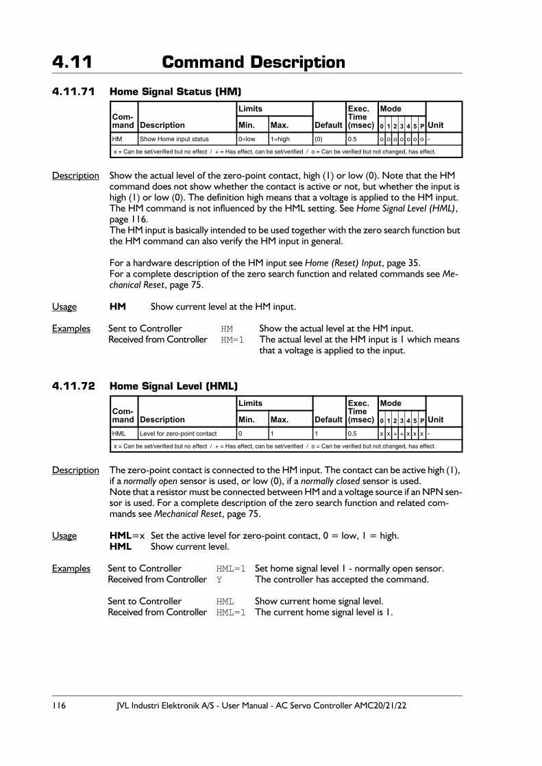
116 JVL Industri Elektronik A/S - User Manual - AC Servo Controller AMC20/21/22
4.11 Command Description
4.11.71 Home Signal Status (HM)
Description Show the actual level of the zero-point contact, high (1) or low (0). Note that the HM command does not show whether the contact is active or not, but whether the input is high (1) or low (0). The definition high means that a voltage is applied to the HM input.The HM command is not influenced by the HML setting. See Home Signal Level (HML), page 116.The HM input is basically intended to be used together with the zero search function but the HM command can also verify the HM input in general.
For a hardware description of the HM input see Home (Reset) Input, page 35.For a complete description of the zero search function and related commands see Me-chanical Reset, page 75.
Usage HM Show current level at the HM input.
Examples Sent to Controller HM Show the actual level at the HM input.Received from Controller HM=1 The actual level at the HM input is 1 which means
that a voltage is applied to the input.
4.11.72 Home Signal Level (HML)
Description The zero-point contact is connected to the HM input. The contact can be active high (1), if a normally open sensor is used, or low (0), if a normally closed sensor is used.Note that a resistor must be connected between HM and a voltage source if an NPN sen-sor is used. For a complete description of the zero search function and related com-mands see Mechanical Reset, page 75.
Usage HML=x Set the active level for zero-point contact, 0 = low, 1 = high.HML Show current level.
Examples Sent to Controller HML=1 Set home signal level 1 - normally open sensor.Received from Controller Y The controller has accepted the command.
Sent to Controller HML Show current home signal level.Received from Controller HML=1 The current home signal level is 1.
Com-mand Description
Limits
Default
Exec.Time(msec)
Mode
UnitMin. Max. 0 1 2 3 4 5 P
HM Show Home input status 0=low 1=high (0) 0.5 o o o o o o o -
x = Can be set/verified but no effect / + = Has effect, can be set/verified / o = Can be verified but not changed, has effect.
Com-mand Description
Limits
Default
Exec.Time(msec)
Mode
UnitMin. Max. 0 1 2 3 4 5 P
HML Level for zero-point contact 0 1 1 0.5 x x + + x x x -
x = Can be set/verified but no effect / + = Has effect, can be set/verified / o = Can be verified but not changed, has effect.
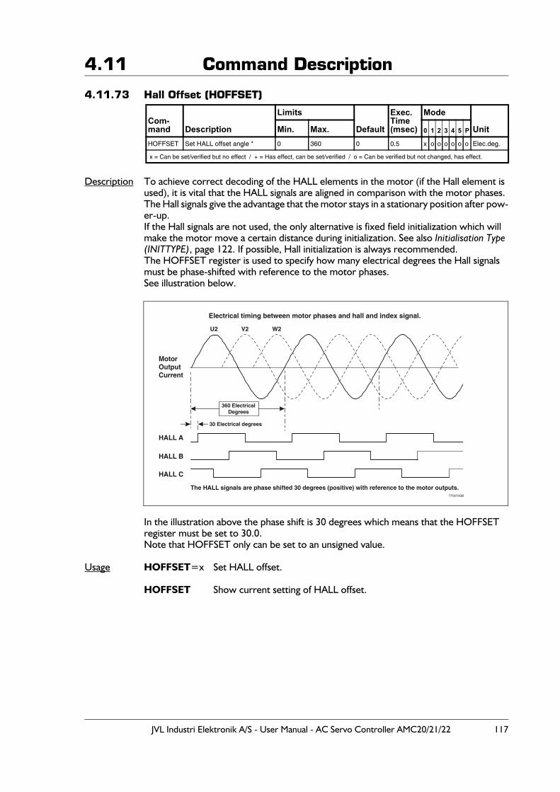
JVL Industri Elektronik A/S - User Manual - AC Servo Controller AMC20/21/22 117
4.11 Command Description
4.11.73 Hall Offset (HOFFSET)
Description To achieve correct decoding of the HALL elements in the motor (if the Hall element is used), it is vital that the HALL signals are aligned in comparison with the motor phases.The Hall signals give the advantage that the motor stays in a stationary position after pow-er-up.If the Hall signals are not used, the only alternative is fixed field initialization which will make the motor move a certain distance during initialization. See also Initialisation Type (INITTYPE), page 122. If possible, Hall initialization is always recommended.The HOFFSET register is used to specify how many electrical degrees the Hall signals must be phase-shifted with reference to the motor phases.See illustration below.
In the illustration above the phase shift is 30 degrees which means that the HOFFSET register must be set to 30.0.Note that HOFFSET only can be set to an unsigned value.
Usage HOFFSET=x Set HALL offset.
HOFFSET Show current setting of HALL offset.
Com-mand Description
Limits
Default
Exec.Time(msec)
Mode
UnitMin. Max. 0 1 2 3 4 5 P
HOFFSET Set HALL offset angle * 0 360 0 0.5 x o o o o o o Elec.deg.
x = Can be set/verified but no effect / + = Has effect, can be set/verified / o = Can be verified but not changed, has effect.
Electrical timing between motor phases and hall and index signal.
U2 V2 W2
HALL A
The HALL signals are phase shifted 30 degrees (positive) with reference to the motor outputs.
HALL C
HALL B
MotorOutputCurrent
360 ElectricalDegrees
30 Electrical degrees
TT0572GB
118 JVL Industri Elektronik A/S - User Manual - AC Servo Controller AMC20/21/22
4.11 Command Description
4.11.74 IF statement (IF) - Only AMC2xP
Description Program execution can be controlled using conditional statements. If the condition spec-ified by the IF statement is true (not 0), the next line in the program is executed. If the statement is false (=0), the next program line is skipped and program execution contin-ues. The ELSE statement can also be used in conjunction with the IF statement. All reg-isters and commands that return a value can be used in IF statements.
The following operators can be used in the statement:
Usage IF statement { OR statement }statement::= expression { AND expression }expression::=value rel_op value (where rel_op is <, >, =, <=, >= or <>)value::= register or equation
Examples IF AC>56 AND IN1=1AC=789
IF IN1=1
IF IN2=1 OR IN3=0 AND IN4=1 OR IN5=1
IF IN5=IN6
IF AC>6+VM-IN1+3*9 OR IN7=1
Com-mand Description
Limits
Default
Exec.Time(msec)
Mode
UnitMin. Max. 0 1 2 3 4 5 P
IF IF statement - - - 0.5 + -
x = Can be set/verified but no effect / + = Has effect, can be set/verified / o = Can be verified but not changed, has effect.
Operator Description< Less than
> Greater than
= Equal to
<= Less than or equal to
>= Greater than or equal to
<> not equal to
AND Logical AND operator
OR Logical OR operator
JVL Industri Elektronik A/S - User Manual - AC Servo Controller AMC20/21/22 119
4.11 Command Description
4.11.75 Verify Flag in External Module - Only AMC2xP
Description Execute next line if flag in external module (connected to the Bus) is equal to the spec-ified logic level. The function can be used to verify a flag or a certain input. If the specified condition is true, the next line in the program is executed.This function can be useful to control the program flow in the AMC2xP, since the only alternative function is the INPUT command Read Data from External Module (INPUT) - Only AMC2xP, page 124. This command however reads a complete register in the exter-nal module and not a single input or flag. The INPUT command therefore requires a fol-lowing mask routine to extract a specific input or flag.
Usage IF I[a].[f]=[l]
Command Format :a Specifies the address of the external module from which input is required. The ad-
dress parameter must be specified as a value between 0 and 31. The JVL Bus inter-face enables up to 32 modules to be connected to the interface. The address of each module must be set via DIP switches on the individual module. Consult the user man-ual for the actual module.
f Specifies the flag or input in the external module from which input is to be read. f must be specified in the range 0-255. Consult the user manual for the actual module to see which flags or inputs are available.
Examples An IOM11 Input/output module is used. The Module address is 2. Input 5 has to be read
and tested to determine if the value is logic 1 (input is activated). If this is the case, the module Counter is read and the program continues. In the instruction manual for the IOM11 module, the Counter register is specified as register 2 and the register for all 16 inputs is 3.
:START IF I2.5=1 ; VERIFY FLAG 5 IN MODULE 2 (ADDRESS 2); IF FLAG IS EQUAL 1 (LOGIC 1), MOVE; MOTOR TO POSITION 5000. OTHRWISE; BYPASS NEXT LINE (SP=5000).
SP=5000 ; MOVE MOTOR TO POSITION 5000OUT1=4 ; ACTIVATE OUTPUT 4
Com-mand Description
Limits
Default
Exec.Time(msec)
Mode
UnitMin. Max. 0 1 2 3 4 5 P
IF (ext) IF statement (External module) - - - 0.5 + -
x = Can be set/verified but no effect / + = Has effect, can be set/verified / o = Can be verified but not changed, has effect.
120 JVL Industri Elektronik A/S - User Manual - AC Servo Controller AMC20/21/22
4.11 Command Description
4.11.76 Read Status of Inputs (IN1 - IN8)
Description The Controller has 8 inputs. The status of these inputs can be read using the IN com-mand.The Inputs have certain pre-defined functions depending on the Controller’s mode of operation. Inputs can be read individually using the INx command, where x specifies the input to be read. All inputs can be read simultaneously using the IN command.
Usage IN Read inputs.INx Read input x
Example Sent to Controller IN4Received from Controller IN4=0
Sent to Controller INReceived from Controller IN=00010100 Note that IN8 is the leftmost digit (MSB)
4.11.77 Input Active Level (INAL)
Range 0 - 255(decimal) or 00000000 - 11111111 (binary)Default 11111111 (all inputs are active high)
Description The active level of the digital inputs can be independently programmed to be active high (1) or active low (0). Active high (1) means that the input is activated when a positive volt-age is applied at the input with reference to the input common terminal IN-. Active low (0) means that the actual input terminal is left open (no voltage applied) with reference to the terminal IN-.
Example All inputs must be active high therefore INAL=11111111 is set.All inputs must be active low therefore INAL=00000000 is set.
Com-mand Description
Limits
Default
Exec.Time(msec)
Mode
UnitMin. Max. 0 1 2 3 4 5 P
IN Read input port status 0 255 - 0.5 o o o o o o o -
x = Can be set/verified but no effect / + = Has effect, can be set/verified / o = Can be verified but not changed, has effect.
Input FunctionRegister Mode (MO=3) All other Modes
IN1 D0 (Least significant bit) General inputIN2 D1 General inputIN3 D2 General inputIN4 D3 General inputIN5 D4 General inputIN6 D5 (Most significant bit) General inputIN7 Pause input General inputIN8 Start / stop input General Input
Com-mand Description
Limits
Default
Exec.Time(msec)
Mode
UnitMin. Max. 0 1 2 3 4 5 P
INAL Input active level 0 255 Decimal11111111 Binary 255 0.5 + + + + + + + -
x = Can be set/verified but no effect / + = Has effect, can be set/verified / o = Can be verified but not changed, has effect.
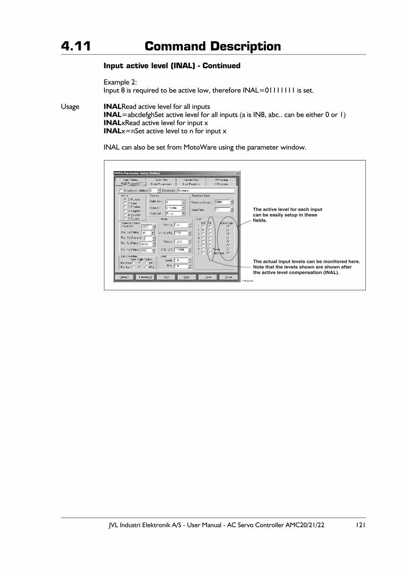
JVL Industri Elektronik A/S - User Manual - AC Servo Controller AMC20/21/22 121
4.11 Command DescriptionInput active level (INAL) - Continued
Example 2:Input 8 is required to be active low, therefore INAL=01111111 is set.
Usage INALRead active level for all inputsINAL=abcdefghSet active level for all inputs (a is IN8, abc.. can be either 0 or 1)INALxRead active level for input xINALx=nSet active level to n for input x
INAL can also be set from MotoWare using the parameter window.
TT9022GB
The active level for each inputcan be easily setup in these fields.
The actual input levels can be monitored here.Note that the levels shown are shown after the active level compensation (INAL).
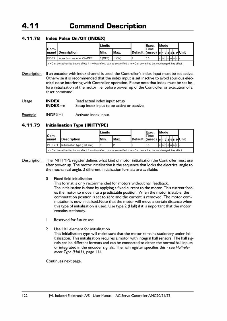
122 JVL Industri Elektronik A/S - User Manual - AC Servo Controller AMC20/21/22
4.11 Command Description
4.11.78 Index Pulse On/Off (INDEX)
Description If an encoder with index channel is used, the Controller’s Index Input must be set active.Otherwise it is recommended that the index input is set inactive to avoid spurious elec-trical noise interfering with Controller operation. Please note that index must be set be-fore initialization of the motor, i.e. before power up of the Controller or execution of a reset command.
Usage INDEX Read actual index input setupINDEX=n Setup index input to be active or passive
Example INDEX=1 Activate index input.
4.11.79 Initialisation Type (INITTYPE)
Description The INITTYPE register defines what kind of motor initialisation the Controller must use after power up. The motor initialisation is the sequence that locks the electrical angle to the mechanical angle. 3 different initialisation formats are available:
0 Fixed field initialisationThis format is only recommended for motors without hall feedback.The initialisation is done by applying a fixed current to the motor. This current forc-es the motor to move into a predictable position. When the motor is stable, the commutation position is set to zero and the current is removed. The motor com-mutation is now initialised.Note that the motor will move a certain distance when this type of initialisation is used. Use type 2 (Hall) if it is important that the motor remains stationary.
1 Reserved for future use
2 Use Hall element for initialisation.This initialisation type will make sure that the motor remains stationary under ini-tialisation. This initialisation requires a motor with integral hall sensors. The hall sig-nals can be different formats and can be connected to either the normal hall inputs or integrated in the encoder signals. The hall register specifies this - see Hall-ele-ment Type (HALL), page 114.
Continues next page.
Com-mand Description
Limits
Default
Exec.Time(msec)
Mode
UnitMin. Max. 0 1 2 3 4 5 P
INDEX Index from encoder ON/OFF 0 (OFF) 1 (ON) 1 0.5 x o o o o o o -
x = Can be set/verified but no effect / + = Has effect, can be set/verified / o = Can be verified but not changed, has effect.
Com-mand Description
Limits
Default
Exec.Time(msec)
Mode
UnitMin. Max. 0 1 2 3 4 5 P
INITTYPE Initialisation type (Hall etc.) 0 2 2 0.5 x o o o o o o -
x = Can be set/verified but no effect / + = Has effect, can be set/verified / o = Can be verified but not changed, has effect.
JVL Industri Elektronik A/S - User Manual - AC Servo Controller AMC20/21/22 123
4.11 Command DescriptionInitialisation type (INITTYPE) - Continued
Usage INITTYPE Read actual inittype setup.INITTYPE=n Set inittype to "n" type.
Example INITTYPE=2 Set initialisation type to Hall element - Use Hall element to initialise after powering up the system.
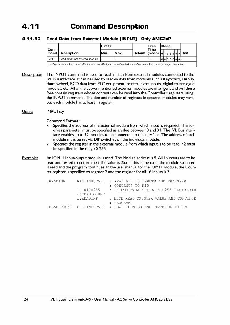
124 JVL Industri Elektronik A/S - User Manual - AC Servo Controller AMC20/21/22
4.11 Command Description
4.11.80 Read Data from External Module (INPUT) - Only AMC2xP
Description The INPUT command is used to read-in data from external modules connected to the JVL Bus interface. It can be used to read-in data from modules such a Keyboard, Display, thumbwheel, BCD data from PLC equipment, printer, extra inputs, digital-to-analogue modules, etc. All of the above-mentioned external modules are intelligent and will there-fore contain registers whose contents can be read into the Controller's registers using the INPUT command. The size and number of registers in external modules may vary, but each module has at least 1 register.
Usage INPUTx.y
Command Format :x Specifies the address of the external module from which input is required. The ad-
dress parameter must be specified as a value between 0 and 31. The JVL Bus inter-face enables up to 32 modules to be connected to the interface. The address of each module must be set via DIP switches on the individual module.
y Specifies the register in the external module from which input is to be read. n2 must be specified in the range 0-255.
Examples An IOM11 Input/output module is used. The Module address is 5. All 16 inputs are to be
read and tested to determine if the value is 255. If this is the case, the module Counter is read and the program continues. In the user manual for the IOM11 module, the Coun-ter register is specified as register 2 and the register for all 16 inputs is 3.
:READINP R10=INPUT5.2 ; READ ALL 16 INPUTS AND TRANSFER; CONTENTS TO R10
IF R10=255 ; IF INPUTS NOT EQUAL TO 255 READ AGAINJ:READ_COUNTJ:READINP ; ELSE READ COUNTER VALUE AND CONTINUE
; PROGRAM:READ_COUNT R30=INPUT5.3 ; READ COUNTER AND TRANSFER TO R30
Com-mand Description
Limits
Default
Exec.Time(msec)
Mode
UnitMin. Max. 0 1 2 3 4 5 P
INPUT Read data from external module - - - 0.5 o o o o o o o -
x = Can be set/verified but no effect / + = Has effect, can be set/verified / o = Can be verified but not changed, has effect.
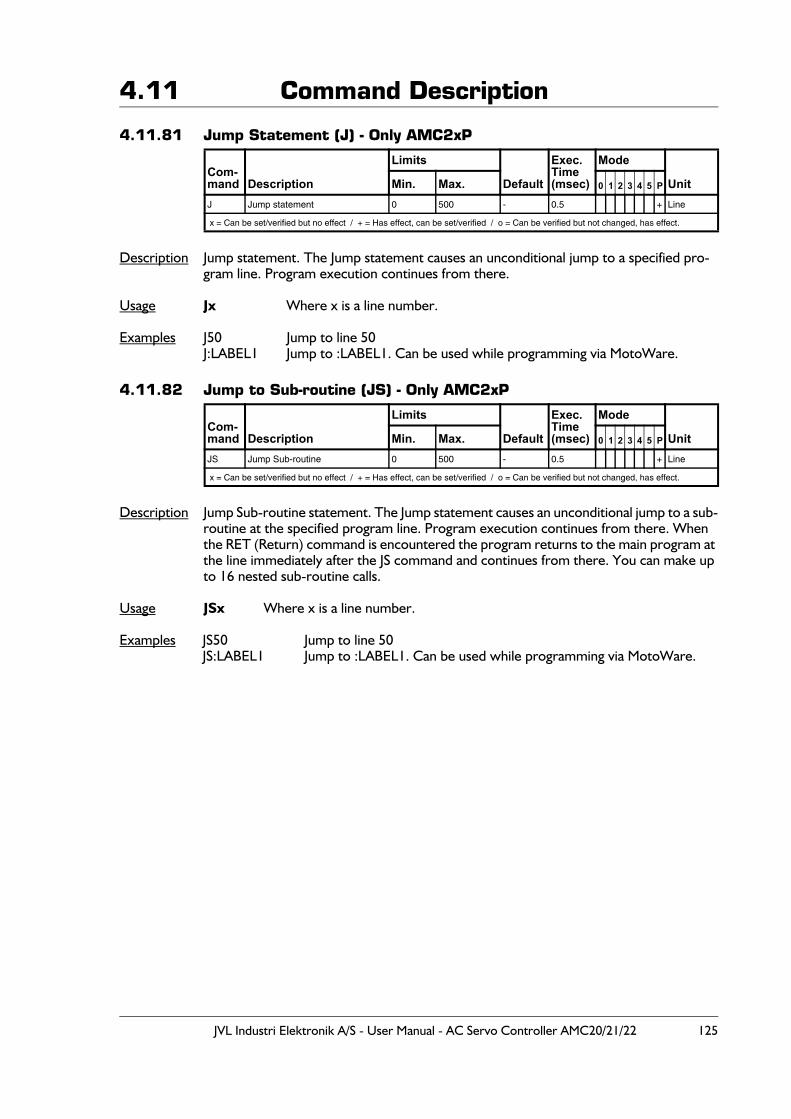
JVL Industri Elektronik A/S - User Manual - AC Servo Controller AMC20/21/22 125
4.11 Command Description
4.11.81 Jump Statement (J) - Only AMC2xP
Description Jump statement. The Jump statement causes an unconditional jump to a specified pro-gram line. Program execution continues from there.
Usage Jx Where x is a line number.
Examples J50 Jump to line 50J:LABEL1 Jump to :LABEL1. Can be used while programming via MotoWare.
4.11.82 Jump to Sub-routine (JS) - Only AMC2xP
Description Jump Sub-routine statement. The Jump statement causes an unconditional jump to a sub-routine at the specified program line. Program execution continues from there. When the RET (Return) command is encountered the program returns to the main program at the line immediately after the JS command and continues from there. You can make up to 16 nested sub-routine calls.
Usage JSx Where x is a line number.
Examples JS50 Jump to line 50JS:LABEL1 Jump to :LABEL1. Can be used while programming via MotoWare.
Com-mand Description
Limits
Default
Exec.Time(msec)
Mode
UnitMin. Max. 0 1 2 3 4 5 P
J Jump statement 0 500 - 0.5 + Line
x = Can be set/verified but no effect / + = Has effect, can be set/verified / o = Can be verified but not changed, has effect.
Com-mand Description
Limits
Default
Exec.Time(msec)
Mode
UnitMin. Max. 0 1 2 3 4 5 P
JS Jump Sub-routine 0 500 - 0.5 + Line
x = Can be set/verified but no effect / + = Has effect, can be set/verified / o = Can be verified but not changed, has effect.
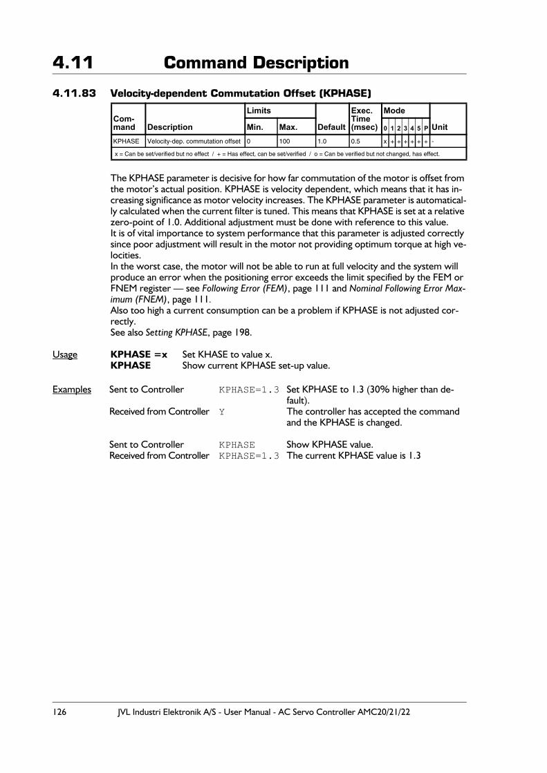
126 JVL Industri Elektronik A/S - User Manual - AC Servo Controller AMC20/21/22
4.11 Command Description
4.11.83 Velocity-dependent Commutation Offset (KPHASE)
The KPHASE parameter is decisive for how far commutation of the motor is offset from the motor’s actual position. KPHASE is velocity dependent, which means that it has in-creasing significance as motor velocity increases. The KPHASE parameter is automatical-ly calculated when the current filter is tuned. This means that KPHASE is set at a relative zero-point of 1.0. Additional adjustment must be done with reference to this value.It is of vital importance to system performance that this parameter is adjusted correctly since poor adjustment will result in the motor not providing optimum torque at high ve-locities. In the worst case, the motor will not be able to run at full velocity and the system will produce an error when the positioning error exceeds the limit specified by the FEM or FNEM register — see Following Error (FEM), page 111 and Nominal Following Error Max-imum (FNEM), page 111.Also too high a current consumption can be a problem if KPHASE is not adjusted cor-rectly.See also Setting KPHASE, page 198.
Usage KPHASE =x Set KHASE to value x.KPHASE Show current KPHASE set-up value.
Examples Sent to Controller KPHASE=1.3 Set KPHASE to 1.3 (30% higher than de-fault).
Received from Controller Y The controller has accepted the command and the KPHASE is changed.
Sent to Controller KPHASE Show KPHASE value.Received from Controller KPHASE=1.3 The current KPHASE value is 1.3
Com-mand Description
Limits
Default
Exec.Time(msec)
Mode
UnitMin. Max. 0 1 2 3 4 5 P
KPHASE Velocity-dep. commutation offset 0 100 1.0 0.5 x + + + + + + -
x = Can be set/verified but no effect / + = Has effect, can be set/verified / o = Can be verified but not changed, has effect.
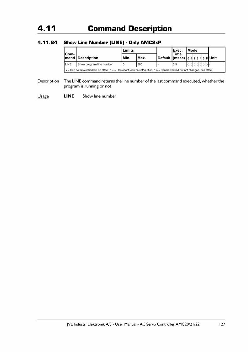
JVL Industri Elektronik A/S - User Manual - AC Servo Controller AMC20/21/22 127
4.11 Command Description
4.11.84 Show Line Number (LINE) - Only AMC2xP
Description The LINE command returns the line number of the last command executed, whether the program is running or not.
Usage LINE Show line number
Com-mand Description
Limits
Default
Exec.Time(msec)
Mode
UnitMin. Max. 0 1 2 3 4 5 P
LINE Show program line number 0 500 - 0.5 o o o o o o o -
x = Can be set/verified but no effect / + = Has effect, can be set/verified / o = Can be verified but not changed, has effect.
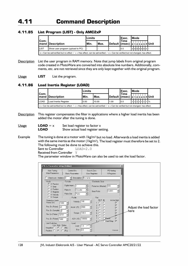
128 JVL Industri Elektronik A/S - User Manual - AC Servo Controller AMC20/21/22
4.11 Command Description
4.11.85 List Program (LIST) - Only AMC2xP
Description List the user program in RAM memory. Note that jump labels from original program code created in MotoWare are converted into absolute line numbers. Additionally, com-ments, etc. are not retrieved since they are only kept together with the original program.
Usage LIST List the program.
4.11.86 Load Inertia Register (LOAD)
Description This register compensates the filter in applications where a higher load inertia has been added the motor after the tuning is done.
Usage LOAD = x Set load register to factor xLOAD Show actual load register setting.
Example The tuning is done at a motor with 1kg/m² but no load. Afterwards a load inertia is added with the same inertia as the motor (1kg/m²). The load register must therefore be set to 2.The following must be done to achieve this.Sent to Controller LOAD=2.0Received from Controller YThe parameter window in MotoWare can also be used to set the load factor.
Com-mand Description
Limits
Default
Exec.Time(msec)
Mode
UnitMin. Max. 0 1 2 3 4 5 P
LIST Show user program (upload to PC) - - - 0.5 o o o o o o o -
x = Can be set/verified but no effect / + = Has effect, can be set/verified / o = Can be verified but not changed, has effect.
Com-mand Description
Limits
Default
Exec.Time(msec)
Mode
UnitMin. Max. 0 1 2 3 4 5 P
LOAD Load Inertia Register 0.50 10.00 1.00 0.5 + + + + + + + %
x = Can be set/verified but no effect / + = Has effect, can be set/verified / o = Can be verified but not changed, has effect.
TT9024GB
Adjust the load factorhere
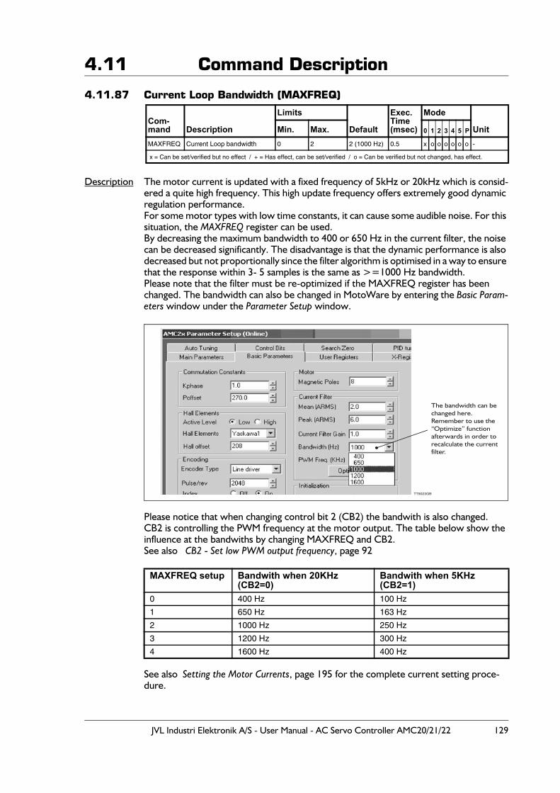
JVL Industri Elektronik A/S - User Manual - AC Servo Controller AMC20/21/22 129
4.11 Command Description
4.11.87 Current Loop Bandwidth (MAXFREQ)
Description The motor current is updated with a fixed frequency of 5kHz or 20kHz which is consid-ered a quite high frequency. This high update frequency offers extremely good dynamic regulation performance.For some motor types with low time constants, it can cause some audible noise. For this situation, the MAXFREQ register can be used.By decreasing the maximum bandwidth to 400 or 650 Hz in the current filter, the noise can be decreased significantly. The disadvantage is that the dynamic performance is also decreased but not proportionally since the filter algorithm is optimised in a way to ensure that the response within 3- 5 samples is the same as >=1000 Hz bandwidth.Please note that the filter must be re-optimized if the MAXFREQ register has been changed. The bandwidth can also be changed in MotoWare by entering the Basic Param-eters window under the Parameter Setup window.
Please notice that when changing control bit 2 (CB2) the bandwith is also changed.CB2 is controlling the PWM frequency at the motor output. The table below show the influence at the bandwiths by changing MAXFREQ and CB2.See also CB2 - Set low PWM output frequency, page 92
See also Setting the Motor Currents, page 195 for the complete current setting proce-dure.
Com-mand Description
Limits
Default
Exec.Time(msec)
Mode
UnitMin. Max. 0 1 2 3 4 5 P
MAXFREQ Current Loop bandwidth 0 2 2 (1000 Hz) 0.5 x o o o o o o -
x = Can be set/verified but no effect / + = Has effect, can be set/verified / o = Can be verified but not changed, has effect.
MAXFREQ setup Bandwith when 20KHz(CB2=0)
Bandwith when 5KHz(CB2=1)
0 400 Hz 100 Hz
1 650 Hz 163 Hz
2 1000 Hz 250 Hz
3 1200 Hz 300 Hz
4 1600 Hz 400 Hz
The bandwidth can bechanged here.Remember to use the“Optimize” function afterwards in order torecalculate the currentfilter.
TT9023GB
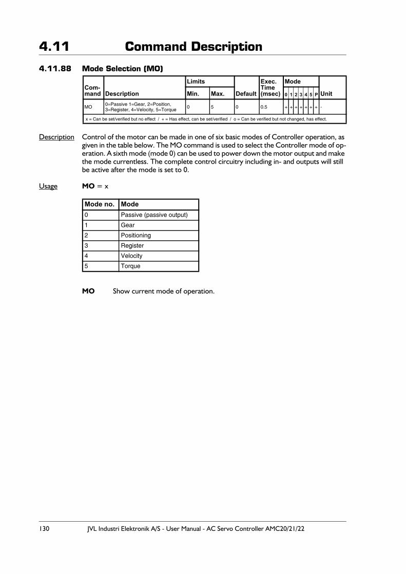
130 JVL Industri Elektronik A/S - User Manual - AC Servo Controller AMC20/21/22
4.11 Command Description
4.11.88 Mode Selection (MO)
Description Control of the motor can be made in one of six basic modes of Controller operation, as given in the table below. The MO command is used to select the Controller mode of op-eration. A sixth mode (mode 0) can be used to power down the motor output and make the mode currentless. The complete control circuitry including in- and outputs will still be active after the mode is set to 0.
Usage MO = x
MO Show current mode of operation.
Com-mand Description
Limits
Default
Exec.Time(msec)
Mode
UnitMin. Max. 0 1 2 3 4 5 P
MO 0=Passive 1=Gear, 2=Position,3=Register, 4=Velocity, 5=Torque 0 5 0 0.5 + + + + + + + -
x = Can be set/verified but no effect / + = Has effect, can be set/verified / o = Can be verified but not changed, has effect.
Mode no. Mode0 Passive (passive output)
1 Gear
2 Positioning
3 Register
4 Velocity
5 Torque
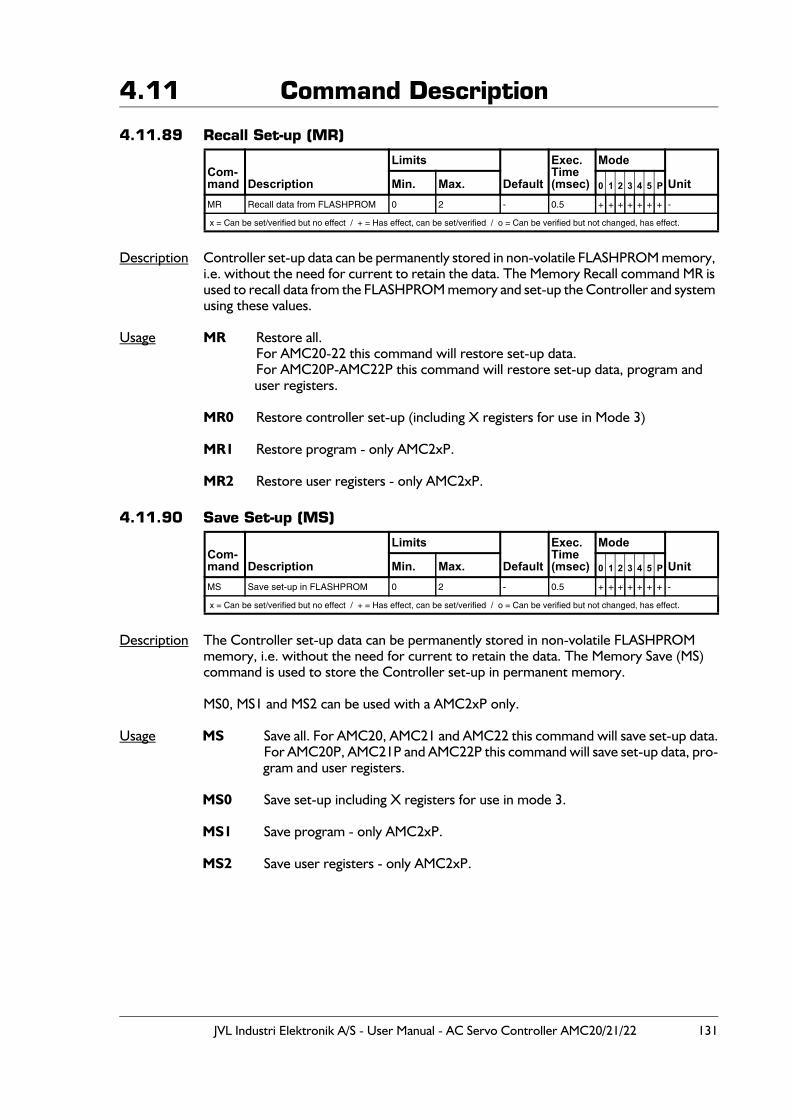
JVL Industri Elektronik A/S - User Manual - AC Servo Controller AMC20/21/22 131
4.11 Command Description
4.11.89 Recall Set-up (MR)
Description Controller set-up data can be permanently stored in non-volatile FLASHPROM memory, i.e. without the need for current to retain the data. The Memory Recall command MR is used to recall data from the FLASHPROM memory and set-up the Controller and system using these values.
Usage MR Restore all.For AMC20-22 this command will restore set-up data.For AMC20P-AMC22P this command will restore set-up data, program and user registers.
MR0 Restore controller set-up (including X registers for use in Mode 3)
MR1 Restore program - only AMC2xP.
MR2 Restore user registers - only AMC2xP.
4.11.90 Save Set-up (MS)
Description The Controller set-up data can be permanently stored in non-volatile FLASHPROM memory, i.e. without the need for current to retain the data. The Memory Save (MS) command is used to store the Controller set-up in permanent memory.
MS0, MS1 and MS2 can be used with a AMC2xP only.
Usage MS Save all. For AMC20, AMC21 and AMC22 this command will save set-up data.For AMC20P, AMC21P and AMC22P this command will save set-up data, pro-gram and user registers.
MS0 Save set-up including X registers for use in mode 3.
MS1 Save program - only AMC2xP.
MS2 Save user registers - only AMC2xP.
Com-mand Description
Limits
Default
Exec.Time(msec)
Mode
UnitMin. Max. 0 1 2 3 4 5 P
MR Recall data from FLASHPROM 0 2 - 0.5 + + + + + + + -
x = Can be set/verified but no effect / + = Has effect, can be set/verified / o = Can be verified but not changed, has effect.
Com-mand Description
Limits
Default
Exec.Time(msec)
Mode
UnitMin. Max. 0 1 2 3 4 5 P
MS Save set-up in FLASHPROM 0 2 - 0.5 + + + + + + + -
x = Can be set/verified but no effect / + = Has effect, can be set/verified / o = Can be verified but not changed, has effect.
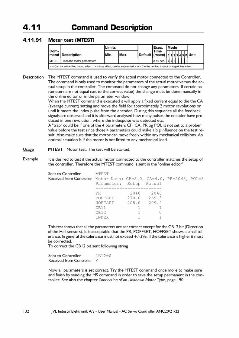
132 JVL Industri Elektronik A/S - User Manual - AC Servo Controller AMC20/21/22
4.11 Command Description
4.11.91 Motor test (MTEST)
Description The MTEST command is used to verify the actual motor connected to the Controller.The command is only used to monitor the parameters of the actual motor versus the ac-tual setup in the controller. The command do not change any parameters. If certain pa-rameters are not equal (set to the correct value) the change must be done manually in the online editor or in the parameter window.When the MTEST command is executed it will apply a fixed current equal to the the CA (average current) setting and move the field for approximately 2 motor revolutions or until it meets the index pulse from the encoder. During this sequence all the feedback signals are observed and it is afterward analysed how many pulses the encoder have pro-duced in one revolution, where the indexpulse was detected etc. A "trap" could be if one of the 4 parameters CP, CA, PR og POL is not set to a prober value before the test since those 4 parameters could make a big influence on the test re-sult. Also make sure that the motor can move freely within any mechanical collisions. An optimal situation is if the motor is not fitted to any mechanical load.
Usage MTEST Motor test. The test will be started.
Example It is desired to test if the actual motor connected to the controller matches the setup of the controller. Therefore the MTEST command is sent in the "online editor".
Sent to Controller MTESTReceived from Controller Motor Data: CP=8.0, CA=4.0, PR=2048, POL=8
Parameter: Setup Actual-------------------------PR 2048 2046POFFSET 270.0 269.3HOFFSET 208.0 209.4CB11 1 1CB12 1 0INDEX 1 1
This test shows that all the parameters are set correct except for the CB12 bit (Direction of the Hall sensors). It is acceptable that the PR, POFFSET, HOFFSET shows a small tol-erance. In general the tolerance must not exceed +/-3%. If the tolerance is higher it must be corrected.To correct the CB12 bit sent following string
Sent to Controller CB12=0Received from Controller Y
Now all parameters is set correct. Try the MTEST command once more to make sure and finish by sending the MS command in order to save the setup permanent in the con-troller. See also the chapter Connection of an Unknown Motor Type, page 190.
Com-mand Description
Limits
Default
Exec.Time(msec)
Mode
UnitMin. Max. 0 1 2 3 4 5 P
MTEST Finds the motor parameters - - - 3-10 sec. + + + + + + + -
x = Can be set/verified but no effect / + = Has effect, can be set/verified / o = Can be verified but not changed, has effect.
JVL Industri Elektronik A/S - User Manual - AC Servo Controller AMC20/21/22 133
4.11 Command Description
4.11.92 Negative Limit signal status (NL)
Description Shows the actual level of the NL (negative limit input), high (1) or low (0). Note that the NL command does not show whether the connected contact is active or not, but wheth-er the input is high (1) or low (0). The definition high means that a voltage is applied to the NL input. The NL command is not influenced by the NLL setting. See Negative Limit Input Level (NLL), page 133.The NL input is basically intended to be used for the negative limit switch, but the NL command can also verify the NL input in general.
For a hardware description of the NL input see End-of-travel Limit Inputs, page 34.
Usage NL Show current level at the NL input.
Examples Sent to Controller NL Show the actual level at the NL input.Received from Controller NL=1 The actual level at the NL input is 1 which means
that a voltage is applied to the input.
4.11.93 Negative Limit Input Level (NLL)
Description The PL and NL Inputs function as end-of-travel limits. If the motor is moving in a negative direction and NL is activated, the motor is stopped instantaneously. The PL Input is the positive end-of-travel input. The two limit switches can be independently programmed to be active high (1=Normally open sensor) or active low (0=Normally closed sensor). The NLL command is used to set this active level for the NL input (positive limit switch).For connection of the end-of-travel inputs, see End-of-travel Limit Inputs, page 34.
Usage NLL=x Set the active level for the negative limit switch sensor connected to the NL input, 0 = low(normally closed), 1 = high(normally open).
NLL Show current active level for the NL input.
Examples Sent to Controller NLL=1 Set NL active level to 1 - normally open sensor.Received from Controller Y The controller has accepted the command.
Sent to Controller NLL Show current NL active level.Received from Controller NLL=1 The current NL active level is 1.
Com-mand Description
Limits
Default
Exec.Time(msec)
Mode
UnitMin. Max. 0 1 2 3 4 5 P
NL Negative Limit input status 0=low 1=high - 0.5 + + + + + + + -
x = Can be set/verified but no effect / + = Has effect, can be set/verified / o = Can be verified but not changed, has effect.
Com-mand Description
Limits
Default
Exec.Time(msec)
Mode
UnitMin. Max. 0 1 2 3 4 5 P
NLL Negative Limit input active Level 0=low 1=high 1 0.5 x x + + x x x -
x = Can be set/verified but no effect / + = Has effect, can be set/verified / o = Can be verified but not changed, has effect.
134 JVL Industri Elektronik A/S - User Manual - AC Servo Controller AMC20/21/22
4.11 Command Description
4.11.94 Logical OR Operator (OR) - Only AMC2xP
Description Logical OR operator. OR can only be used in conditional IF statements and is used when only one of the conditional expressions is required to be fulfilled.
Usage IF expression OR expression
Example IF VM<>500 OR AC=750
4.11.95 Read/Set Status of Outputs (O1 - O8)
Description The 8 user outputs can be set or read by this command. The status of these outputs can be read or set using the OUT command. The OUT command is expressed in decimal values. If the output level must be defined in binary, a # character is added after the com-mand - see following examples. Note that the 8 LEDs O1 - O8 at the Controller front panel always show the actual levels at the respective outputs.Outputs 1 and 2 are by default dedicated for use as "In position" and "Controller OK" out-puts. The functionality of these outputs can however be redefined - see :CB4 - Position Output (O1) Function, page 92.CB15 - Function of User Output 1 (O1), page 96.CB16 - Function of User Output 2 (O2), page 96CB17 - Function of User Output 3 (O3), page 96
Continued on following page.
Com-mand Description
Limits
Default
Exec.Time(msec)
Mode
UnitMin. Max. 0 1 2 3 4 5 P
OR Logical OR operator - - - 0.5 + -
x = Can be set/verified but no effect / + = Has effect, can be set/verified / o = Can be verified but not changed, has effect.
Com-mand Description
Limits
Default
Exec.Time(msec)
Mode
UnitMin. Max. 0 1 2 3 4 5 P
OUT Show/set levels at User Outputs 0 255 0 0.5 + + + + + + + -
x = Can be set/verified but no effect / + = Has effect, can be set/verified / o = Can be verified but not changed, has effect.
Bit no. Output Function
0 O1Default used as "In position output". Default levels : 1 = In position (only used in mode 2 and 3). CB4 and CB15 control the function of this out-put. Output 1 can also be used as a general output.
1 O2Default used as "Controller OK".Default levels : 0 = Fatal error(s), 1 = Controller OK. CB16 controls the function of this output. Output 2 can also be used as a general output.
2 O3 Output 3. Can be used via the OUT command. Output 3 can also be used to control a brake - see CB17 description.
3 O4 Output 4. Can be used via the OUT command
4 O5 Output 5. Can be used via the OUT command
5 O6 Output 6. Can be used via the OUT command
6 O7 Output 7. Can be used via the OUT command
7 O8 Output 8. Can be used via the OUT command
JVL Industri Elektronik A/S - User Manual - AC Servo Controller AMC20/21/22 135
4.11 Command DescriptionUsage OUT Read status of outputs
OUT n Read status of output n (n=1 to 8)OUT n=x Set output n to x (0 or 1)OUT# =xxxxxxxx Set all outputs to x, where x is 0 or 1.OUT = x Set all 8 outputs to decimal value x (x= 0-255)
Examples Sent to Controller OUT Read outputs as a decimal value.Received from Controller OUT=0 Which means that all outputs (O1-O8)
are passive (logic 0).Sent to Controller OUT3=1 Set O3 to 1Received from Controller Y
Sent to Indexer Out#=1010 Sets outputs to 00001010Received from Indexer Y All digits to the left of MSB will be set
to 0
Sent to Indexer OUT# Read outputsReceived from Indexer OUT#=00001010 Note O1 is the rightmost digit (LSB)
Sent to Indexer OUT=255 Sets all outputs to 1Received from Indexer Y
4.11.96 Toggle a Single OutputIn some applications it can be necessary to toggle a single output. Toggling means that a specific output is changed from active to passive or visa versa. Use OUTx=1-OUTx.
Example Sent to Controller OUT5=1-OUT5 Toggle output 5.Received from Controller Y Which means that the output is now tog-
gled. If the output was active before the command was executed, it will now be passive and visa versa.
136 JVL Industri Elektronik A/S - User Manual - AC Servo Controller AMC20/21/22
4.11 Command Description
4.11.97 Maximum Pulse Error (PE)
Description To determine when the motor is in position, the RS register is normally used - see Report Motor Status (RS), page 147. The state of RS is partly controlled by PE since PE specifies the interval in which the final position of the motor is accepted. RS is set according to the following conditions :RS=0 Motor in position. The position is within the number of pulses specified by PE.RS=1 Motor is accelerating.RS=2 Motor is running at constant speed.RS=3 Motor is decelerating.RS=4 Motor in position but the position is outside the tolerance specified by PE.
As shown, RS will change depending on the actual motor status. PE only has effect when the motor theoretically is stopped at the final position. If the interval specified by PE is fulfilled, RS is 0. If not RS is set to 4.The table below shows the conversion between PE values and the actual number of pulses.
The Running LED also depends on the RS register, which means that the Running LED is only lit when RS is equal 0 (position within PE). Note that PES (Position Error Samples) also determines the state of RS.
Usage PE = x Set pulse errorPE Show current Pulse Error limit
Com-mand Description
Limits
Default
Exec.Time(msec)
Mode
UnitMin. Max. 0 1 2 3 4 5 P
PE Maximum Pulse Error 0 15 7 0.5 x + + + ( pulses )
x = Can be set/verified but no effect / + = Has effect, can be set/verified / o = Can be verified but not changed, has effect.
PE Value Pulses PE Value Pulses0 2 8 601 3 9 902 5 10 1353 8 11 2024 12 12 3035 18 13 4546 27 14 6827 (default) 40 15 1024
Velocity
RS
Stable systemwith low
acceleration
Unstablesystem
with highacceleration
TT0562GB
Time
Time
The system is unstablesince the accelerationvalue is too high.The motor torqueis not enough tohandle the load
Position Error is greater than theinterval specified in the PE registertherefore RS is set to 4.
432103210 0
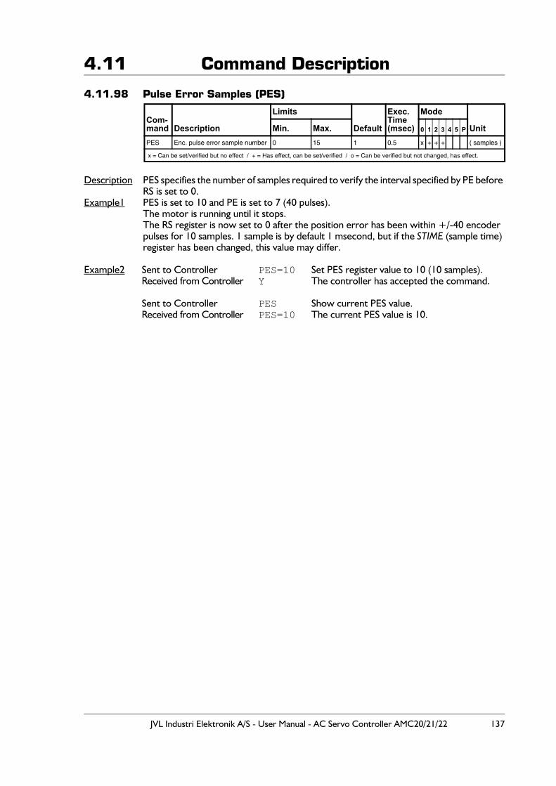
JVL Industri Elektronik A/S - User Manual - AC Servo Controller AMC20/21/22 137
4.11 Command Description
4.11.98 Pulse Error Samples (PES)
Description PES specifies the number of samples required to verify the interval specified by PE before RS is set to 0.
Example1 PES is set to 10 and PE is set to 7 (40 pulses).The motor is running until it stops.The RS register is now set to 0 after the position error has been within +/-40 encoder pulses for 10 samples. 1 sample is by default 1 msecond, but if the STIME (sample time) register has been changed, this value may differ.
Example2 Sent to Controller PES=10 Set PES register value to 10 (10 samples).Received from Controller Y The controller has accepted the command.
Sent to Controller PES Show current PES value.Received from Controller PES=10 The current PES value is 10.
Com-mand Description
Limits
Default
Exec.Time(msec)
Mode
UnitMin. Max. 0 1 2 3 4 5 P
PES Enc. pulse error sample number 0 15 1 0.5 x + + + ( samples )
x = Can be set/verified but no effect / + = Has effect, can be set/verified / o = Can be verified but not changed, has effect.
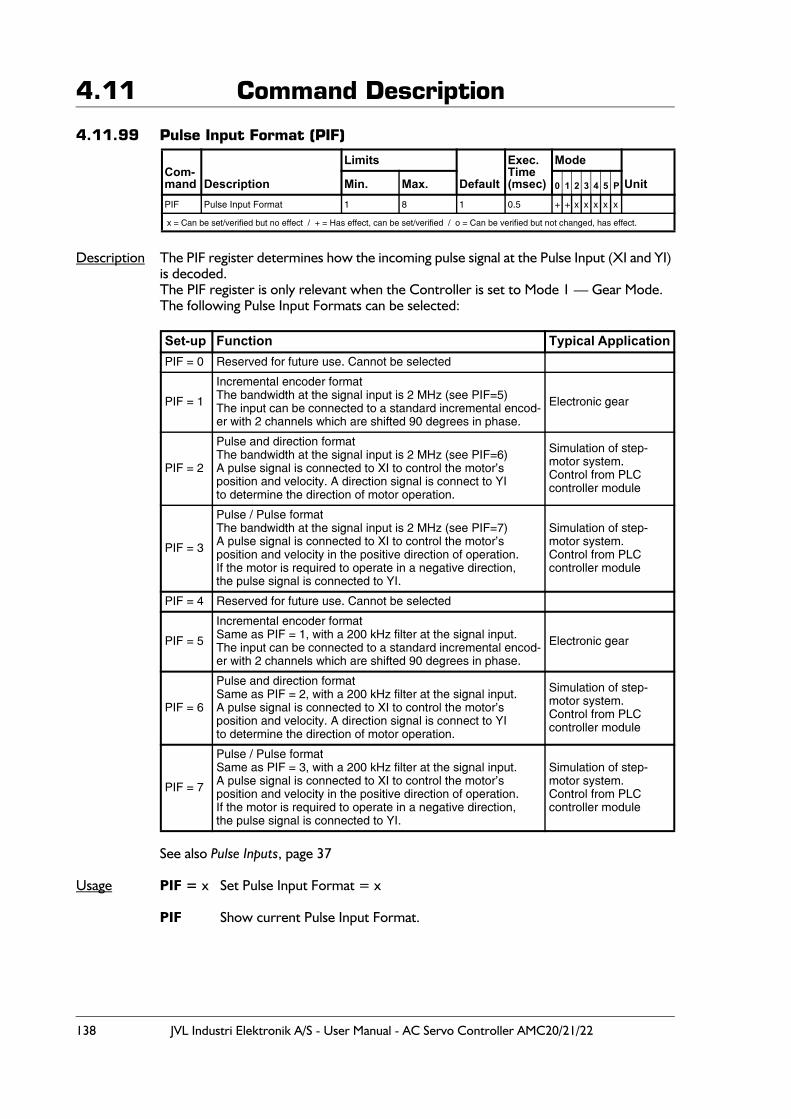
138 JVL Industri Elektronik A/S - User Manual - AC Servo Controller AMC20/21/22
4.11 Command Description
4.11.99 Pulse Input Format (PIF)
Description The PIF register determines how the incoming pulse signal at the Pulse Input (XI and YI) is decoded. The PIF register is only relevant when the Controller is set to Mode 1 — Gear Mode.The following Pulse Input Formats can be selected:
See also Pulse Inputs, page 37
Usage PIF = x Set Pulse Input Format = x
PIF Show current Pulse Input Format.
Com-mand Description
Limits
Default
Exec.Time(msec)
Mode
UnitMin. Max. 0 1 2 3 4 5 P
PIF Pulse Input Format 1 8 1 0.5 + + x x x x x
x = Can be set/verified but no effect / + = Has effect, can be set/verified / o = Can be verified but not changed, has effect.
Set-up Function Typical ApplicationPIF = 0 Reserved for future use. Cannot be selected
PIF = 1
Incremental encoder formatThe bandwidth at the signal input is 2 MHz (see PIF=5)The input can be connected to a standard incremental encod-er with 2 channels which are shifted 90 degrees in phase.
Electronic gear
PIF = 2
Pulse and direction formatThe bandwidth at the signal input is 2 MHz (see PIF=6)A pulse signal is connected to XI to control the motor’sposition and velocity. A direction signal is connect to YI to determine the direction of motor operation.
Simulation of step-motor system.Control from PLCcontroller module
PIF = 3
Pulse / Pulse formatThe bandwidth at the signal input is 2 MHz (see PIF=7)A pulse signal is connected to XI to control the motor’s position and velocity in the positive direction of operation.If the motor is required to operate in a negative direction,the pulse signal is connected to YI.
Simulation of step-motor system.Control from PLCcontroller module
PIF = 4 Reserved for future use. Cannot be selected
PIF = 5
Incremental encoder formatSame as PIF = 1, with a 200 kHz filter at the signal input.The input can be connected to a standard incremental encod-er with 2 channels which are shifted 90 degrees in phase.
Electronic gear
PIF = 6
Pulse and direction formatSame as PIF = 2, with a 200 kHz filter at the signal input.A pulse signal is connected to XI to control the motor’sposition and velocity. A direction signal is connect to YI to determine the direction of motor operation.
Simulation of step-motor system.Control from PLCcontroller module
PIF = 7
Pulse / Pulse formatSame as PIF = 3, with a 200 kHz filter at the signal input.A pulse signal is connected to XI to control the motor’s position and velocity in the positive direction of operation.If the motor is required to operate in a negative direction,the pulse signal is connected to YI.
Simulation of step-motor system.Control from PLCcontroller module
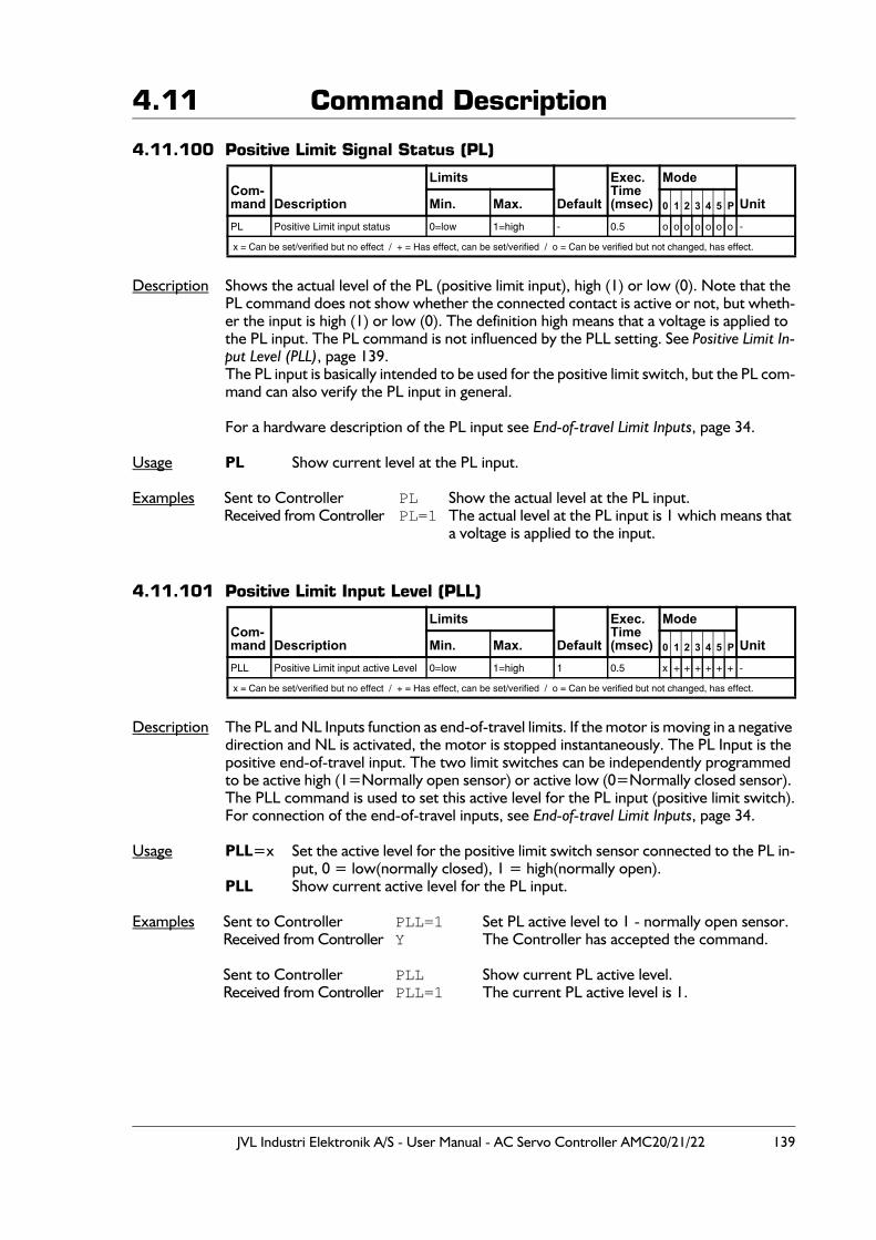
JVL Industri Elektronik A/S - User Manual - AC Servo Controller AMC20/21/22 139
4.11 Command Description
4.11.100 Positive Limit Signal Status (PL)
Description Shows the actual level of the PL (positive limit input), high (1) or low (0). Note that the PL command does not show whether the connected contact is active or not, but wheth-er the input is high (1) or low (0). The definition high means that a voltage is applied to the PL input. The PL command is not influenced by the PLL setting. See Positive Limit In-put Level (PLL), page 139.The PL input is basically intended to be used for the positive limit switch, but the PL com-mand can also verify the PL input in general.
For a hardware description of the PL input see End-of-travel Limit Inputs, page 34.
Usage PL Show current level at the PL input.
Examples Sent to Controller PL Show the actual level at the PL input.Received from Controller PL=1 The actual level at the PL input is 1 which means that
a voltage is applied to the input.
4.11.101 Positive Limit Input Level (PLL)
Description The PL and NL Inputs function as end-of-travel limits. If the motor is moving in a negative direction and NL is activated, the motor is stopped instantaneously. The PL Input is the positive end-of-travel input. The two limit switches can be independently programmed to be active high (1=Normally open sensor) or active low (0=Normally closed sensor). The PLL command is used to set this active level for the PL input (positive limit switch).For connection of the end-of-travel inputs, see End-of-travel Limit Inputs, page 34.
Usage PLL=x Set the active level for the positive limit switch sensor connected to the PL in-put, 0 = low(normally closed), 1 = high(normally open).
PLL Show current active level for the PL input.
Examples Sent to Controller PLL=1 Set PL active level to 1 - normally open sensor.Received from Controller Y The Controller has accepted the command.
Sent to Controller PLL Show current PL active level.Received from Controller PLL=1 The current PL active level is 1.
Com-mand Description
Limits
Default
Exec.Time(msec)
Mode
UnitMin. Max. 0 1 2 3 4 5 P
PL Positive Limit input status 0=low 1=high - 0.5 o o o o o o o -
x = Can be set/verified but no effect / + = Has effect, can be set/verified / o = Can be verified but not changed, has effect.
Com-mand Description
Limits
Default
Exec.Time(msec)
Mode
UnitMin. Max. 0 1 2 3 4 5 P
PLL Positive Limit input active Level 0=low 1=high 1 0.5 x + + + + + + -
x = Can be set/verified but no effect / + = Has effect, can be set/verified / o = Can be verified but not changed, has effect.
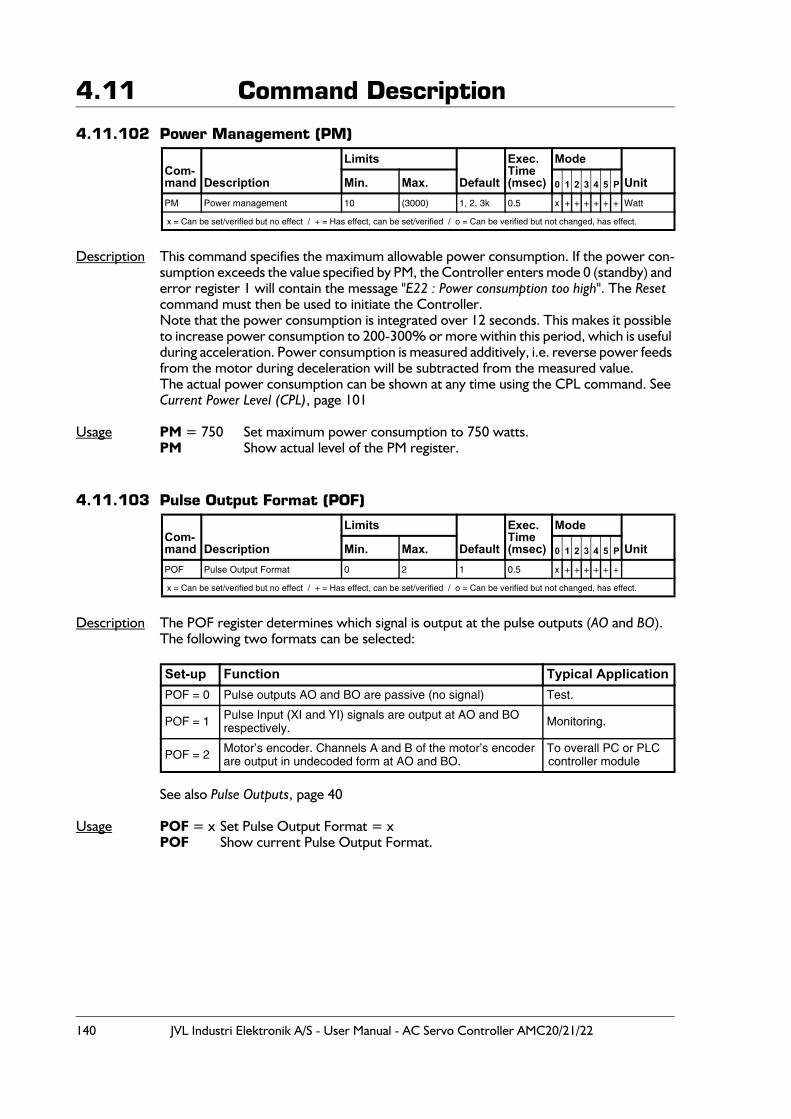
140 JVL Industri Elektronik A/S - User Manual - AC Servo Controller AMC20/21/22
4.11 Command Description
4.11.102 Power Management (PM)
Description This command specifies the maximum allowable power consumption. If the power con-sumption exceeds the value specified by PM, the Controller enters mode 0 (standby) and error register 1 will contain the message "E22 : Power consumption too high". The Reset command must then be used to initiate the Controller.Note that the power consumption is integrated over 12 seconds. This makes it possible to increase power consumption to 200-300% or more within this period, which is useful during acceleration. Power consumption is measured additively, i.e. reverse power feeds from the motor during deceleration will be subtracted from the measured value. The actual power consumption can be shown at any time using the CPL command. See Current Power Level (CPL), page 101
Usage PM = 750 Set maximum power consumption to 750 watts.PM Show actual level of the PM register.
4.11.103 Pulse Output Format (POF)
Description The POF register determines which signal is output at the pulse outputs (AO and BO).The following two formats can be selected:
See also Pulse Outputs, page 40
Usage POF = x Set Pulse Output Format = xPOF Show current Pulse Output Format.
Com-mand Description
Limits
Default
Exec.Time(msec)
Mode
UnitMin. Max. 0 1 2 3 4 5 P
PM Power management 10 (3000) 1, 2, 3k 0.5 x + + + + + + Watt
x = Can be set/verified but no effect / + = Has effect, can be set/verified / o = Can be verified but not changed, has effect.
Com-mand Description
Limits
Default
Exec.Time(msec)
Mode
UnitMin. Max. 0 1 2 3 4 5 P
POF Pulse Output Format 0 2 1 0.5 x + + + + + +
x = Can be set/verified but no effect / + = Has effect, can be set/verified / o = Can be verified but not changed, has effect.
Set-up Function Typical ApplicationPOF = 0 Pulse outputs AO and BO are passive (no signal) Test.
POF = 1 Pulse Input (XI and YI) signals are output at AO and BOrespectively. Monitoring.
POF = 2 Motor’s encoder. Channels A and B of the motor’s encoderare output in undecoded form at AO and BO.
To overall PC or PLC controller module
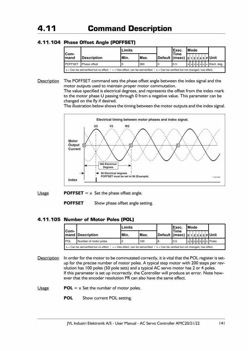
JVL Industri Elektronik A/S - User Manual - AC Servo Controller AMC20/21/22 141
4.11 Command Description
4.11.104 Phase Offset Angle (POFFSET)
Description The POFFSET command sets the phase offset angle between the index signal and the motor outputs used to maintain proper motor commutation.The value specified is electrical degrees, and represents the offset from the index mark to the motor phase U passing through 0 from a negative value. This parameter can be changed on the fly if desired.The illustration below shows the timing between the motor outputs and the index signal.
Usage POFFSET = x Set the phase offset angle.
POFFSET Show phase offset angle setting.
4.11.105 Number of Motor Poles (POL)
Description In order for the motor to be commutated correctly, it is vital that the POL register is set-up for the precise number of motor poles. A typical step motor with 200 steps per rev-olution has 100 poles (50 pole sets) and a typical AC servo motor has 2 or 4 poles.If this parameter is set up incorrectly, the Controller will produce an error. Note how-ever that the encoder resolution PR can also have the same effect.
Usage POL = x Set the number of motor poles.
POL Show current POL setting.
Com-mand Description
Limits
Default
Exec.Time(msec)
Mode
UnitMin. Max. 0 1 2 3 4 5 P
POFFSET Phase offset 0 360 0 0.5 x + + + + + + Elect. deg.
x = Can be set/verified but no effect / + = Has effect, can be set/verified / o = Can be verified but not changed, has effect.
Com-mand Description
Limits
Default
Exec.Time(msec)
Mode
UnitMin. Max. 0 1 2 3 4 5 P
POL Number of motor poles 2 100 8 0.5 x o o o o o o Poles
x = Can be set/verified but no effect / + = Has effect, can be set/verified / o = Can be verified but not changed, has effect.
Electrical timing between motor phases and index signal.
U2 V2 W2
Index
MotorOutputCurrent
360 ElectricalDegrees
90 Electrical degreesPOFFSET must be set to 90 (Example) TT0576GB
0 0 0
142 JVL Industri Elektronik A/S - User Manual - AC Servo Controller AMC20/21/22
4.11 Command Description
4.11.106 Encoder Pulses (PR)
Description To achieve correct velocity and commutation of the motor, the number of encoder lines per revolution must be programmed. The value specified here must be the resolution specified for the encoder. Note that the Controller internally multiplies this resolution by a factor of 4, so that for example an encoder/motor with a resolution of 500 lines per revolution effectively has a resolution of 2000 pulses per revolution. If the motor is to rotate 1 revolution, the posi-tioning command must be based on the effective resolution of 2000 pulses.PR cannot be set to a value lower than the number of motor poles times 128. If PR is set lower, the Controller responds with an error message: E2: Out of range
Usage PR = x Set encoder pulses per revolution.PR Show encoder pulses per revolution.
Example Sent to Controller PR Show the actual PR setting.Received from Controller PR=500 The actual number of encoder lines per revolu-
tion is set to 500, which means that the total counts per revolution is 2000.
Com-mand Description
Limits
Default
Exec.Time(msec)
Mode
UnitMin. Max. 0 1 2 3 4 5 P
PR Pulses per revolution 100 50000 8192 0.5 x + + + + + + Pulses
x = Can be set/verified but no effect / + = Has effect, can be set/verified / o = Can be verified but not changed, has effect.
JVL Industri Elektronik A/S - User Manual - AC Servo Controller AMC20/21/22 143
4.11 Command Description
4.11.107 Print to External Module (PRINT) - Only AMC2xP
Description The Print command is used to print out the contents of registers to external modules. At present, print-out to 4 external modules is possible: to a PC via the RS232 interface and to DIS10, KDM10 and IOM11 Modules via the JVL Bus interface.
Usage PRINTn1.n2.n3
n1 Specifies the address of the module to be printed to (1-31). Address 255 is re-served for a PC.
n2 Specifies the register or cursor position to be printed to in the external module. n3 Specifies the register, numeric value or text string in the Controller to be printed.
When n3 is a string, then the string contains two types of objects: ordinary charac-ters, which are simply copied to the display, and conversion specifications, each of which causes conversion and printing of the next successive argument to PRINT. Each conversion specification is introduced by the character % and ended by a conversion character. If a decimal number is included in the successive argument, then the argument must be surrounded by parentheses. E.g. (CA*1.5).The conversion characters and their meanings are:% To print a single ’%’ include two ’%’ in the string like "%%"c The argument is taken to be a single characteri The argument is taken to be a 16-bit integer in the range (-32768 to 32767)l The argument is taken to be a 32-bit integer (-2.147.483.647 to
+2.147.483.647)f The argument is taken to be a 32-bit decimal number ("floating- point")
number with one decimal. .nf The argument is taken to be a 32-bit decimal number ("floating- point")
number with n numbers of decimals. n must be in the range 0 to 4.
Example 1: PRINT1.0.R23
Prints the contents of register R23 to the module whose interface address is 1. Since transmission via the JVL Bus interface is balanced, it is possible to locate external modules up to 500 metres from the Controller.
Example 2: PRINT255.0."TEST"
Prints the text "TEST" to a PC via the RS232 interface. Address 255 is reserved as the address for PCs. Note that the Print command can be used to print out register contents at run-time. It is especially well-suited for debugging a program. If JVL's MotoWare pro-gram is used, once the Controller program has been transferred, the online feature can be used to display when a Print command is executed at run-time.
Com-mand Description
Limits
Default
Exec.Time(msec)
Mode
UnitMin. Max. 0 1 2 3 4 5 P
PRINT Print to external moduleAddress: 0Register: 0Value: 0
Address: 31Register: 65535Value: 65535 -or text
- 0.5 + + + + + + +
x = Can be set/verified but no effect / + = Has effect, can be set/verified / o = Can be verified but not changed, has effect.
144 JVL Industri Elektronik A/S - User Manual - AC Servo Controller AMC20/21/22
4.11 Command DescriptionPrint to External Module (PRINT) Cont. - Only AMC2xP
Example 3: PRINT3.41."Key in Value: "
When a Keyboard-Display Module KDM10 is incorporated in a system, it is often desir-able to display information to the user. The above example illustrates how text can be written to the module's LCD display. In the example, the address of the module is 3. The second parameter value is cursor position 41, which is the first character on line 2 of the display.
Example 4: R1=5555 // ASSIGN A VALUE OF 5555 TO REGISTER R1 R30=333 // ASSIGN A VALUE OF 333 TO REGISTER R30
PRINT5.41.R1 // PRINT THE CONTENTS OF REGISTER R1 TO CURSOR// POSITION 41 OF A KDM10 MODULE WITH ADDRESS 5
PRINT2.0.R30 // PRINT THE CONTENTS OF REGISTER R30 TO THE // DISPLAY// OF A DIS10 MODULE WITH ADDRESS 2
When external modules DIS10 or KDM10 are used in a system, it is often necessary to print out the contents of register on the displays of the modules. As illustrated in the above example, this is best accomplished using the PRINT command to print the con-tents of a register either to a cursor position or directly to the LED display of the DIS10 module.
Example 5: PRINT3.41."ACT. POSITION:%l".AP
// PRINT THE STRING ACT.POSITION AND THE VALUE OF// ACTUAL POSITION REGISTER TO CURSOR POSITION // OF A KDM10 MODULE WITH ADDRESS 3.
PRINT3.1."IN:%i%i%i%i%i%i%i%i".IN8.IN7.IN6.IN5.IN4.IN3.IN2.IN1
// PRINT INPUTS 8-1 (IN8-IN1)
The above example illustrates how a text string including conversion specifications can be written to the module's LCD display.
Example 6: PRINT3.41."CP=%.1f".(CP*1.5)
The above example illustrates how a decimal value can be included in a text string.
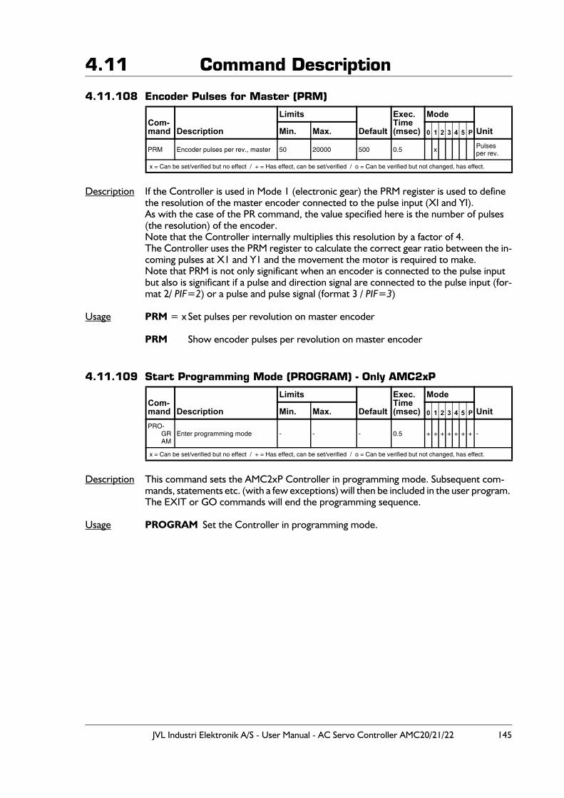
JVL Industri Elektronik A/S - User Manual - AC Servo Controller AMC20/21/22 145
4.11 Command Description
4.11.108 Encoder Pulses for Master (PRM)
Description If the Controller is used in Mode 1 (electronic gear) the PRM register is used to define the resolution of the master encoder connected to the pulse input (XI and YI).As with the case of the PR command, the value specified here is the number of pulses (the resolution) of the encoder. Note that the Controller internally multiplies this resolution by a factor of 4.The Controller uses the PRM register to calculate the correct gear ratio between the in-coming pulses at X1 and Y1 and the movement the motor is required to make. Note that PRM is not only significant when an encoder is connected to the pulse input but also is significant if a pulse and direction signal are connected to the pulse input (for-mat 2/ PIF=2) or a pulse and pulse signal (format 3 / PIF=3)
Usage PRM = x Set pulses per revolution on master encoder
PRM Show encoder pulses per revolution on master encoder
4.11.109 Start Programming Mode (PROGRAM) - Only AMC2xP
Description This command sets the AMC2xP Controller in programming mode. Subsequent com-mands, statements etc. (with a few exceptions) will then be included in the user program. The EXIT or GO commands will end the programming sequence.
Usage PROGRAM Set the Controller in programming mode.
Com-mand Description
Limits
Default
Exec.Time(msec)
Mode
UnitMin. Max. 0 1 2 3 4 5 P
PRM Encoder pulses per rev., master 50 20000 500 0.5 x Pulsesper rev.
x = Can be set/verified but no effect / + = Has effect, can be set/verified / o = Can be verified but not changed, has effect.
Com-mand Description
Limits
Default
Exec.Time(msec)
Mode
UnitMin. Max. 0 1 2 3 4 5 P
PRO-GRAM
Enter programming mode - - - 0.5 + + + + + + + -
x = Can be set/verified but no effect / + = Has effect, can be set/verified / o = Can be verified but not changed, has effect.
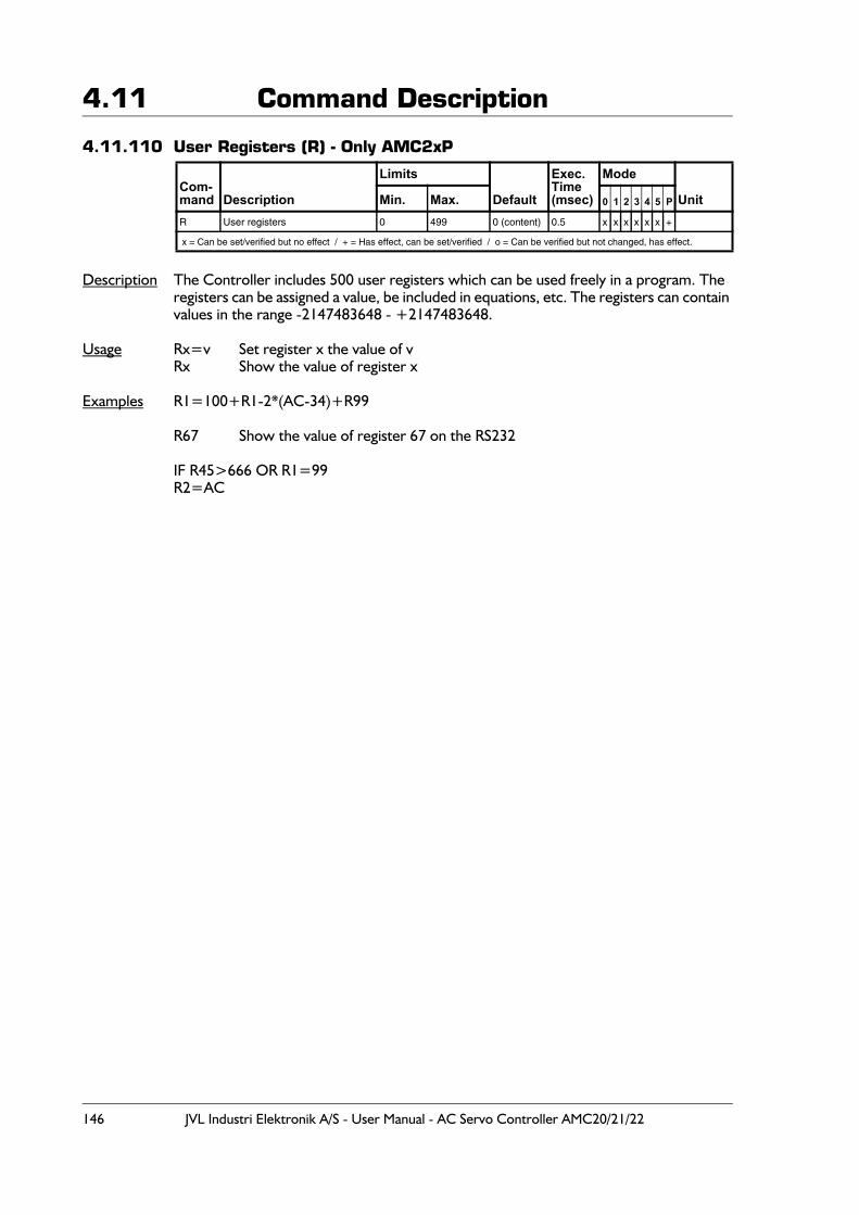
146 JVL Industri Elektronik A/S - User Manual - AC Servo Controller AMC20/21/22
4.11 Command Description
4.11.110 User Registers (R) - Only AMC2xP
Description The Controller includes 500 user registers which can be used freely in a program. The registers can be assigned a value, be included in equations, etc. The registers can contain values in the range -2147483648 - +2147483648.
Usage Rx=v Set register x the value of vRx Show the value of register x
Examples R1=100+R1-2*(AC-34)+R99
R67 Show the value of register 67 on the RS232
IF R45>666 OR R1=99R2=AC
Com-mand Description
Limits
Default
Exec.Time(msec)
Mode
UnitMin. Max. 0 1 2 3 4 5 P
R User registers 0 499 0 (content) 0.5 x x x x x x +
x = Can be set/verified but no effect / + = Has effect, can be set/verified / o = Can be verified but not changed, has effect.
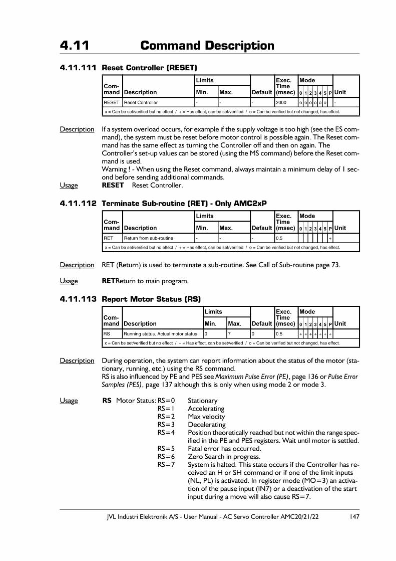
JVL Industri Elektronik A/S - User Manual - AC Servo Controller AMC20/21/22 147
4.11 Command Description
4.11.111 Reset Controller (RESET)
Description If a system overload occurs, for example if the supply voltage is too high (see the ES com-mand), the system must be reset before motor control is possible again. The Reset com-mand has the same effect as turning the Controller off and then on again. The Controller’s set-up values can be stored (using the MS command) before the Reset com-mand is used.Warning ! - When using the Reset command, always maintain a minimum delay of 1 sec-ond before sending additional commands.
Usage RESET Reset Controller.
4.11.112 Terminate Sub-routine (RET) - Only AMC2xP
Description RET (Return) is used to terminate a sub-routine. See Call of Sub-routine page 73.
Usage RETReturn to main program.
4.11.113 Report Motor Status (RS)
Description During operation, the system can report information about the status of the motor (sta-tionary, running, etc.) using the RS command.RS is also influenced by PE and PES see Maximum Pulse Error (PE), page 136 or Pulse Error Samples (PES), page 137 although this is only when using mode 2 or mode 3.
Usage RS Motor Status: RS=0 StationaryRS=1 AcceleratingRS=2 Max velocityRS=3 DeceleratingRS=4 Position theoretically reached but not within the range spec-
ified in the PE and PES registers. Wait until motor is settled.RS=5 Fatal error has occurred.RS=6 Zero Search in progress.RS=7 System is halted. This state occurs if the Controller has re-
ceived an H or SH command or if one of the limit inputs (NL, PL) is activated. In register mode (MO=3) an activa-tion of the pause input (IN7) or a deactivation of the start input during a move will also cause RS=7.
Com-mand Description
Limits
Default
Exec.Time(msec)
Mode
UnitMin. Max. 0 1 2 3 4 5 P
RESET Reset Controller - - - 2000 o o o o o o -
x = Can be set/verified but no effect / + = Has effect, can be set/verified / o = Can be verified but not changed, has effect.
Com-mand Description
Limits
Default
Exec.Time(msec)
Mode
UnitMin. Max. 0 1 2 3 4 5 P
RET Return from sub-routine - - - 0.5 +
x = Can be set/verified but no effect / + = Has effect, can be set/verified / o = Can be verified but not changed, has effect.
Com-mand Description
Limits
Default
Exec.Time(msec)
Mode
UnitMin. Max. 0 1 2 3 4 5 P
RS Running status. Actual motor status 0 7 0 0.5 + + + + + + +
x = Can be set/verified but no effect / + = Has effect, can be set/verified / o = Can be verified but not changed, has effect.
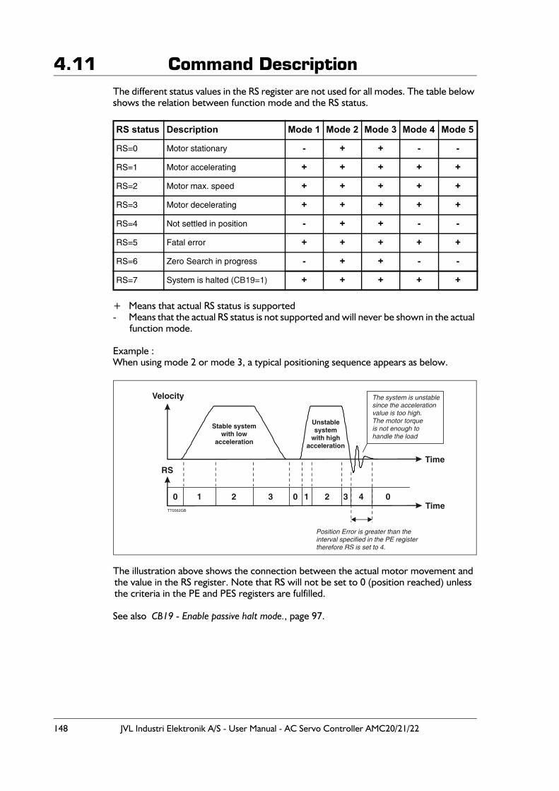
148 JVL Industri Elektronik A/S - User Manual - AC Servo Controller AMC20/21/22
4.11 Command DescriptionThe different status values in the RS register are not used for all modes. The table below shows the relation between function mode and the RS status.
+ Means that actual RS status is supported- Means that the actual RS status is not supported and will never be shown in the actual
function mode.
Example :When using mode 2 or mode 3, a typical positioning sequence appears as below.
The illustration above shows the connection between the actual motor movement and the value in the RS register. Note that RS will not be set to 0 (position reached) unless the criteria in the PE and PES registers are fulfilled.
See also CB19 - Enable passive halt mode., page 97.
RS status Description Mode 1 Mode 2 Mode 3 Mode 4 Mode 5
RS=0 Motor stationary - + + - -
RS=1 Motor accelerating + + + + +
RS=2 Motor max. speed + + + + +
RS=3 Motor decelerating + + + + +
RS=4 Not settled in position - + + - -
RS=5 Fatal error + + + + +
RS=6 Zero Search in progress - + + - -
RS=7 System is halted (CB19=1) + + + + +
Velocity
RS
Stable systemwith low
acceleration
Unstablesystem
with highacceleration
TT0562GB
Time
Time
The system is unstablesince the accelerationvalue is too high.The motor torqueis not enough tohandle the load
Position Error is greater than theinterval specified in the PE registertherefore RS is set to 4.
432103210 0
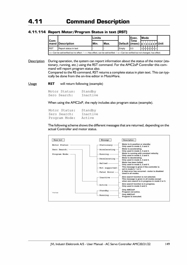
JVL Industri Elektronik A/S - User Manual - AC Servo Controller AMC20/21/22 149
4.11 Command Description
4.11.114 Report Motor/Program Status in text (RST)
Description During operation, the system can report information about the status of the motor (sta-tionary, running, etc.) using the RST command. For the AMC2xP Controller this com-mand will report program status also.Compared to the RS command, RST returns a complete status in plain text. This can typ-ically be done from the on-line editor in MotoWare.
Usage RST will return following (example)
Motor Status: StandbyZero Search: Inactive
When using the AMC2xP, the reply includes also program status (example).
Motor Status: StandbyZero Search: InactiveProgram Mode: Active
The following scheme shows the different messages that are returned, depending on the actual Controller and motor status.
Com-mand Description
Limits
Default
Exec.Time(msec)
Mode
UnitMin. Max. 0 1 2 3 4 5 P
RST Report status in text - - Empty 0.5 + + + + + + +
x = Can be set/verified but no effect / + = Has effect, can be set/verified / o = Can be verified but not changed, has effect.
Motor Status:Zero Search:Program Mode:
StationaryAcceleratingRunningDeceleratingHaltedNot supportedFatal Error
Inactive
StandbyRunning
Active
Motor is in position or standbyOnly used in mode 2, 3 and 4.
Message :Base text : Description :
Motor is accelerating.Only used in mode 2, 3 and 4.Motor is running with constant velocity.Only used in mode 2, 3 and 4.Motor is decelerating.Only used in mode 2, 3 and 4.Motor has been halted.Only used in mode 2, 3 and 4.This message is given if the controller isset in mode 0, 1 or 5.A fatal error has occurred - motor is disabledUsed in all modes.
Zero search function is not selected.This message is given in all modes exceptwhen zero search is in progress in mode 2 or 3.
Zero search function is in progress.Only used in mode 2 and 3.
Only AMC2xP.Program not active.Only AMC2xP.Program is executed.
TT0573GB
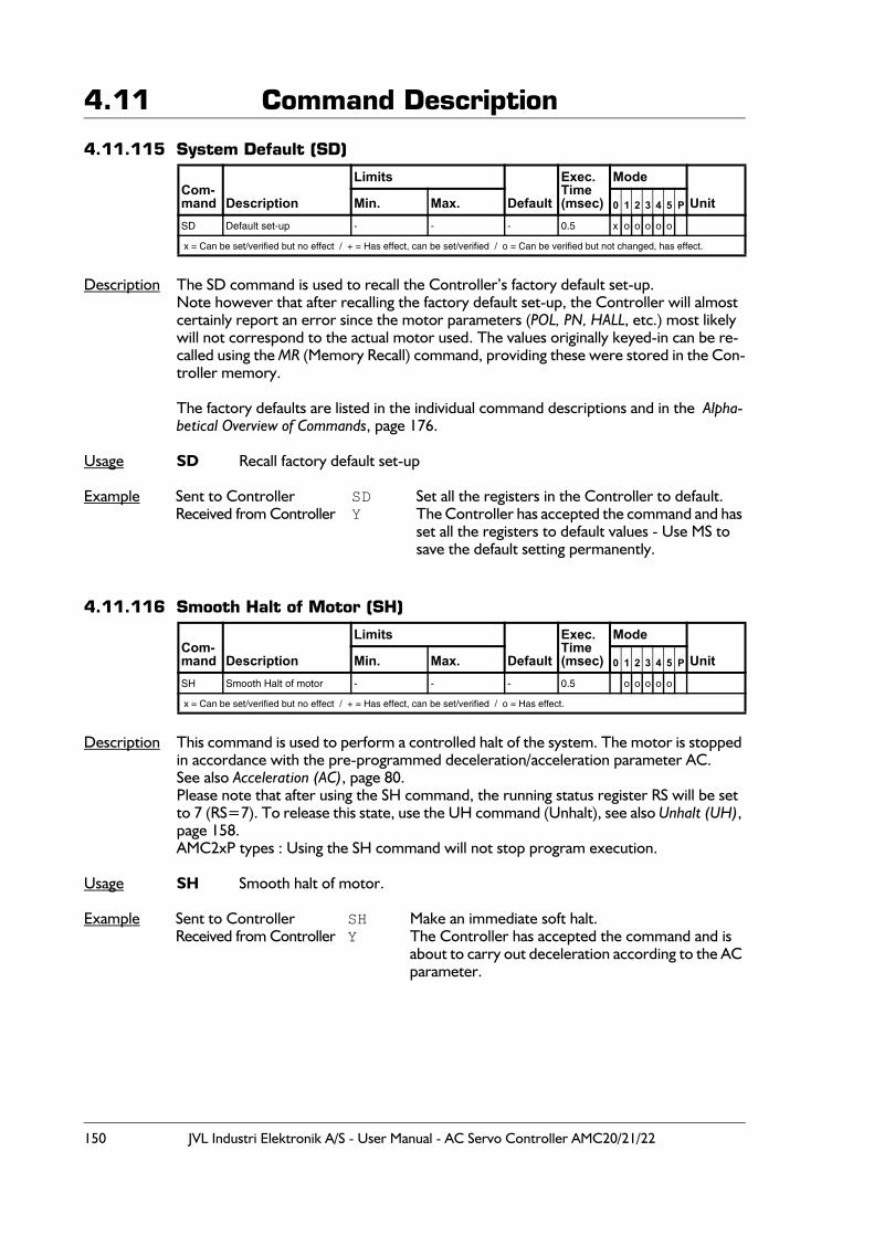
150 JVL Industri Elektronik A/S - User Manual - AC Servo Controller AMC20/21/22
4.11 Command Description
4.11.115 System Default (SD)
Description The SD command is used to recall the Controller’s factory default set-up.Note however that after recalling the factory default set-up, the Controller will almost certainly report an error since the motor parameters (POL, PN, HALL, etc.) most likely will not correspond to the actual motor used. The values originally keyed-in can be re-called using the MR (Memory Recall) command, providing these were stored in the Con-troller memory.
The factory defaults are listed in the individual command descriptions and in the Alpha-betical Overview of Commands, page 176.
Usage SD Recall factory default set-up
Example Sent to Controller SD Set all the registers in the Controller to default.Received from Controller Y The Controller has accepted the command and has
set all the registers to default values - Use MS to save the default setting permanently.
4.11.116 Smooth Halt of Motor (SH)
Description This command is used to perform a controlled halt of the system. The motor is stopped in accordance with the pre-programmed deceleration/acceleration parameter AC.See also Acceleration (AC), page 80.Please note that after using the SH command, the running status register RS will be set to 7 (RS=7). To release this state, use the UH command (Unhalt), see also Unhalt (UH), page 158.AMC2xP types : Using the SH command will not stop program execution.
Usage SH Smooth halt of motor.
Example Sent to Controller SH Make an immediate soft halt.Received from Controller Y The Controller has accepted the command and is
about to carry out deceleration according to the AC parameter.
Com-mand Description
Limits
Default
Exec.Time(msec)
Mode
UnitMin. Max. 0 1 2 3 4 5 P
SD Default set-up - - - 0.5 x o o o o o
x = Can be set/verified but no effect / + = Has effect, can be set/verified / o = Can be verified but not changed, has effect.
Com-mand Description
Limits
Default
Exec.Time(msec)
Mode
UnitMin. Max. 0 1 2 3 4 5 P
SH Smooth Halt of motor - - - 0.5 o o o o o
x = Can be set/verified but no effect / + = Has effect, can be set/verified / o = Has effect.
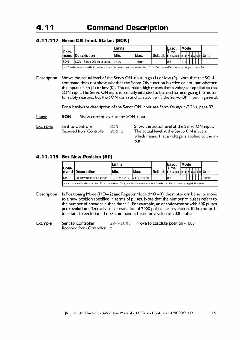
JVL Industri Elektronik A/S - User Manual - AC Servo Controller AMC20/21/22 151
4.11 Command Description
4.11.117 Servo ON Input Status (SON)
Description Shows the actual level of the Servo ON input, high (1) or low (0). Note that the SON command does not show whether the Servo ON function is active or not, but whether the input is high (1) or low (0). The definition high means that a voltage is applied to the SON input.The Servo ON input is basically intended to be used for energizing the motor for safety reasons, but the SON command can also verify the Servo ON input in general.
For a hardware description of the Servo ON input see Servo On Input (SON), page 32.
Usage SON Show current level at the SON input.
Examples Sent to Controller SON Show the actual level at the Servo ON input.Received from Controller SON=1 The actual level at the Servo ON input is 1
which means that a voltage is applied to the in-put.
4.11.118 Set New Position (SP)
Description In Positioning Mode (MO=2) and Register Mode (MO=3), the motor can be set to move to a new position specified in terms of pulses. Note that the number of pulses refers to the number of encoder pulses times 4. For example, an encoder/motor with 500 pulses per revolution effectively has a resolution of 2000 pulses per revolution. If the motor is to rotate 1 revolution, the SP command is based on a value of 2000 pulses.
Example Sent to Controller SP=-1000 Move to absolute position -1000Received from Controller Y
Com-mand Description
Limits
Default
Exec.Time(msec)
Mode
UnitMin. Max. 0 1 2 3 4 5 P
SON SON - Servo ON input status 0=low 1=high - 0.5 + + + + + + + -
x = Can be set/verified but no effect / + = Has effect, can be set/verified / o = Can be verified but not changed, has effect.
Com-mand Description
Limits
Default
Exec.Time(msec)
Mode
UnitMin. Max. 0 1 2 3 4 5 P
SP Set new absolute position - 2147483647 2147483648 0 0.5 + + Pulses
x = Can be set/verified but no effect / + = Has effect, can be set/verified / o = Can be verified but not changed, has effect.
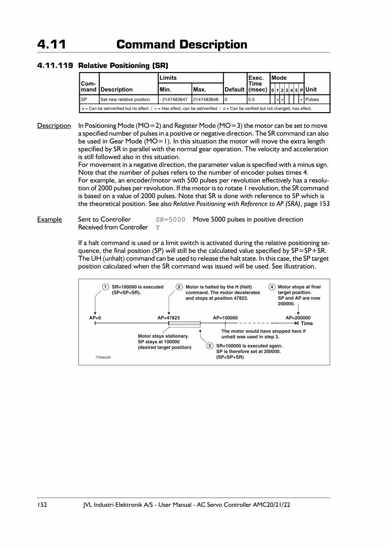
152 JVL Industri Elektronik A/S - User Manual - AC Servo Controller AMC20/21/22
4.11 Command Description
4.11.119 Relative Positioning (SR)
Description In Positioning Mode (MO=2) and Register Mode (MO=3) the motor can be set to move a specified number of pulses in a positive or negative direction. The SR command can also be used in Gear Mode (MO=1). In this situation the motor will move the extra length specified by SR in parallel with the normal gear operation. The velocity and acceleration is still followed also in this situation. For movement in a negative direction, the parameter value is specified with a minus sign. Note that the number of pulses refers to the number of encoder pulses times 4.For example, an encoder/motor with 500 pulses per revolution effectively has a resolu-tion of 2000 pulses per revolution. If the motor is to rotate 1 revolution, the SR command is based on a value of 2000 pulses. Note that SR is done with reference to SP which is the theoretical position. See also Relative Positioning with Reference to AP (SRA), page 153
Example Sent to Controller SR=5000 Move 5000 pulses in positive directionReceived from Controller Y
If a halt command is used or a limit switch is activated during the relative positioning se-quence, the final position (SP) will still be the calculated value specified by SP=SP+SR. The UH (unhalt) command can be used to release the halt state. In this case, the SP target position calculated when the SR command was issued will be used. See illustration.
Com-mand Description
Limits
Default
Exec.Time(msec)
Mode
UnitMin. Max. 0 1 2 3 4 5 P
SP Set new relative position - 2147483647 2147483648 0 0.5 + + + Pulses
x = Can be set/verified but no effect / + = Has effect, can be set/verified / o = Can be verified but not changed, has effect.
AP=0 AP=47823 AP=100000 AP=200000
1 2
3
4SR=100000 is executed(SP=SP+SR).
Motor is halted by the H (Halt)command. The motor deceleratesand stops at position 47823.
SR=100000 is executed again.SP is therefore set at 200000.(SP=SP+SR)
Motor stops at finaltarget position.SP and AP are now200000.
Motor stays stationary.SP stays at 100000(desired target position)
TT0582GB
The motor would have stopped here ifunhalt was used in step 3.
Time
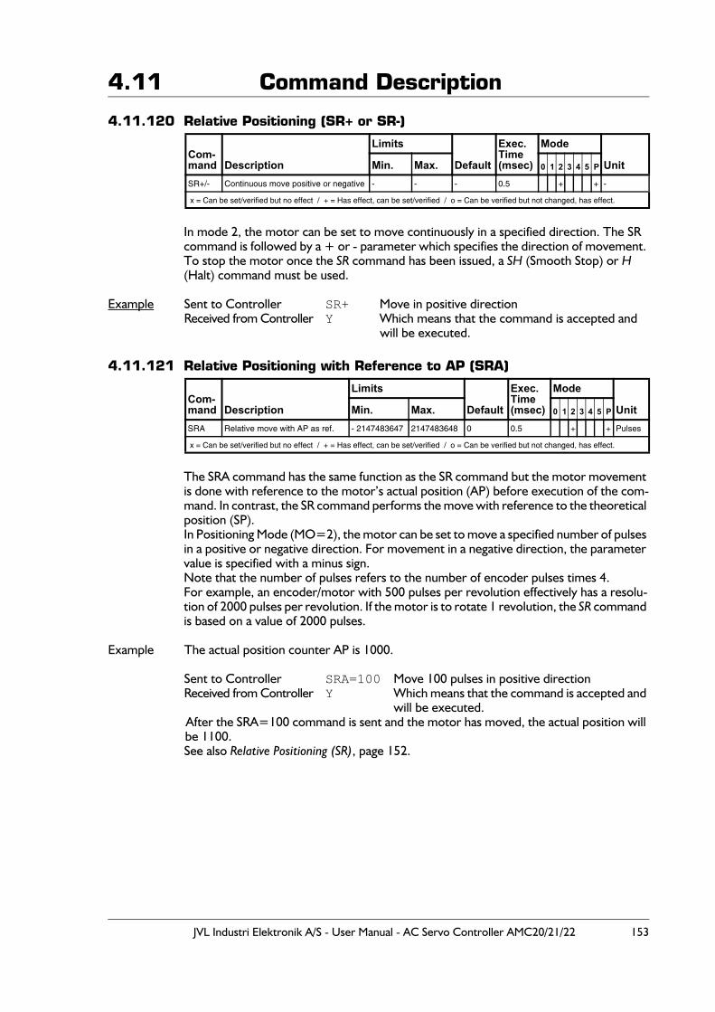
JVL Industri Elektronik A/S - User Manual - AC Servo Controller AMC20/21/22 153
4.11 Command Description
4.11.120 Relative Positioning (SR+ or SR-)
In mode 2, the motor can be set to move continuously in a specified direction. The SR command is followed by a + or - parameter which specifies the direction of movement. To stop the motor once the SR command has been issued, a SH (Smooth Stop) or H (Halt) command must be used.
Example Sent to Controller SR+ Move in positive directionReceived from Controller Y Which means that the command is accepted and
will be executed.
4.11.121 Relative Positioning with Reference to AP (SRA)
The SRA command has the same function as the SR command but the motor movement is done with reference to the motor’s actual position (AP) before execution of the com-mand. In contrast, the SR command performs the move with reference to the theoretical position (SP).In Positioning Mode (MO=2), the motor can be set to move a specified number of pulses in a positive or negative direction. For movement in a negative direction, the parameter value is specified with a minus sign. Note that the number of pulses refers to the number of encoder pulses times 4.For example, an encoder/motor with 500 pulses per revolution effectively has a resolu-tion of 2000 pulses per revolution. If the motor is to rotate 1 revolution, the SR command is based on a value of 2000 pulses.
Example The actual position counter AP is 1000.
Sent to Controller SRA=100 Move 100 pulses in positive directionReceived from Controller Y Which means that the command is accepted and
will be executed.After the SRA=100 command is sent and the motor has moved, the actual position will be 1100.See also Relative Positioning (SR), page 152.
Com-mand Description
Limits
Default
Exec.Time(msec)
Mode
UnitMin. Max. 0 1 2 3 4 5 P
SR+/- Continuous move positive or negative - - - 0.5 + + -
x = Can be set/verified but no effect / + = Has effect, can be set/verified / o = Can be verified but not changed, has effect.
Com-mand Description
Limits
Default
Exec.Time(msec)
Mode
UnitMin. Max. 0 1 2 3 4 5 P
SRA Relative move with AP as ref. - 2147483647 2147483648 0 0.5 + + Pulses
x = Can be set/verified but no effect / + = Has effect, can be set/verified / o = Can be verified but not changed, has effect.
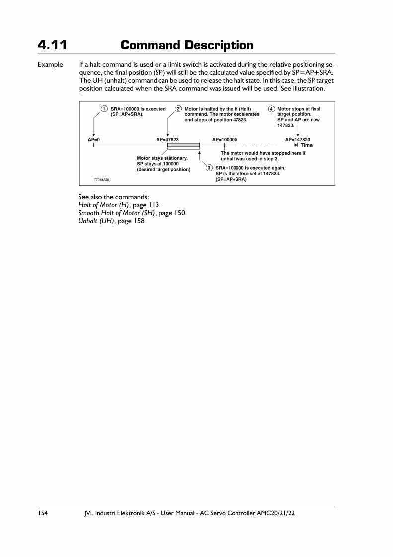
154 JVL Industri Elektronik A/S - User Manual - AC Servo Controller AMC20/21/22
4.11 Command DescriptionExample If a halt command is used or a limit switch is activated during the relative positioning se-
quence, the final position (SP) will still be the calculated value specified by SP=AP+SRA. The UH (unhalt) command can be used to release the halt state. In this case, the SP target position calculated when the SRA command was issued will be used. See illustration.
See also the commands:Halt of Motor (H), page 113.Smooth Halt of Motor (SH), page 150.Unhalt (UH), page 158
AP=0 AP=47823 AP=100000 AP=147823
1 2
3
4SRA=100000 is executed(SP=AP+SRA).
Motor is halted by the H (Halt)command. The motor deceleratesand stops at position 47823.
SRA=100000 is executed again.SP is therefore set at 147823.(SP=AP+SRA)
Motor stops at finaltarget position.SP and AP are now147823.
Motor stays stationary.SP stays at 100000(desired target position)
TT0583GB
The motor would have stopped here ifunhalt was used in step 3.
Time

JVL Industri Elektronik A/S - User Manual - AC Servo Controller AMC20/21/22 155
4.11 Command Description
4.11.122 Sample Time (STIME)
Description The sample time for the outer servo filter can be adjusted using this command.The outer servo filter covers the position loop and the speed loop. The current loop filter that controls the current to the motor cannot be adjusted and is fixed to 50 µS (20kHz). The resolution for the sample rate is 0.05 msecond.If high inertias are applied to the motor, the sample rate must be increased.A more detailed description is given in Adjustment of Servo Regulation, page 18
Usage STIME = x Set servo filter sample time.STIME Show servo filter sample time.
Example Sent to Controller STIME=5.0 Set sample time to 5.0 msecond (200Hz).Received from Controller Y The Controller has accepted the command -
sample time is now changed.
Sent to Controller STIME Show the actual sample time setting.Received from Controller STIME=5.0 The actual sample time is set at 5.0 second.
4.11.123 Search Zero Point (SZ)
Description This command is used to reset the motor position to a known zero point.See also Home (Reset) Input, page 35 or Mechanical Reset, page 75
Usage SZ Begin zero point search.
Example Sent to Controller SZ Begin zero search.Received from Controller Y The Controller has accepted the command.
Com-mand Description
Limits
Default
Exec.Time(msec)
Mode
UnitMin. Max. 0 1 2 3 4 5 P
STIME Show/set update time pos./velocity loop 0.2 30.0 1 0.5 x o o o o o o mSec.
x = Can be set/verified but no effect / + = Has effect, can be set/verified / o = Can be verified but not changed, has effect.
Com-mand Description
Limits
Default
Exec.Time(msec)
Mode
UnitMin. Max. 0 1 2 3 4 5 P
SZ Search zero-point - - - 0.5 + + -
x = Can be set/verified but no effect / + = Has effect, can be set/verified / o = Can be verified but not changed, has effect.
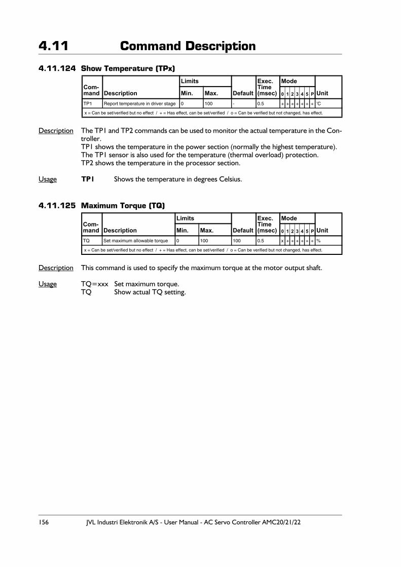
156 JVL Industri Elektronik A/S - User Manual - AC Servo Controller AMC20/21/22
4.11 Command Description
4.11.124 Show Temperature (TPx)
Description The TP1 and TP2 commands can be used to monitor the actual temperature in the Con-troller. TP1 shows the temperature in the power section (normally the highest temperature). The TP1 sensor is also used for the temperature (thermal overload) protection. TP2 shows the temperature in the processor section.
Usage TP1 Shows the temperature in degrees Celsius.
4.11.125 Maximum Torque (TQ)
Description This command is used to specify the maximum torque at the motor output shaft.
Usage TQ=xxx Set maximum torque.TQ Show actual TQ setting.
Com-mand Description
Limits
Default
Exec.Time(msec)
Mode
UnitMin. Max. 0 1 2 3 4 5 P
TP1 Report temperature in driver stage 0 100 - 0.5 + + + + + + + ’C
x = Can be set/verified but no effect / + = Has effect, can be set/verified / o = Can be verified but not changed, has effect.
Com-mand Description
Limits
Default
Exec.Time(msec)
Mode
UnitMin. Max. 0 1 2 3 4 5 P
TQ Set maximum allowable torque 0 100 100 0.5 x + + + + + + %
x = Can be set/verified but no effect / + = Has effect, can be set/verified / o = Can be verified but not changed, has effect.
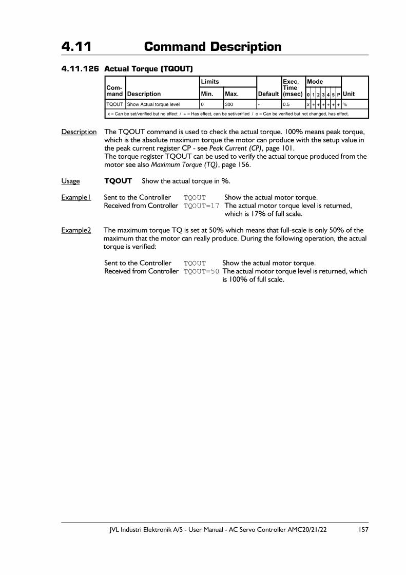
JVL Industri Elektronik A/S - User Manual - AC Servo Controller AMC20/21/22 157
4.11 Command Description
4.11.126 Actual Torque (TQOUT)
Description The TQOUT command is used to check the actual torque. 100% means peak torque, which is the absolute maximum torque the motor can produce with the setup value in the peak current register CP - see Peak Current (CP), page 101.The torque register TQOUT can be used to verify the actual torque produced from the motor see also Maximum Torque (TQ), page 156.
Usage TQOUT Show the actual torque in %.
Example1 Sent to the Controller TQOUT Show the actual motor torque.Received from Controller TQOUT=17 The actual motor torque level is returned,
which is 17% of full scale.
Example2 The maximum torque TQ is set at 50% which means that full-scale is only 50% of the maximum that the motor can really produce. During the following operation, the actual torque is verified:
Sent to the Controller TQOUT Show the actual motor torque.Received from Controller TQOUT=50 The actual motor torque level is returned, which
is 100% of full scale.
Com-mand Description
Limits
Default
Exec.Time(msec)
Mode
UnitMin. Max. 0 1 2 3 4 5 P
TQOUT Show Actual torque level 0 300 - 0.5 x + + + + + + %
x = Can be set/verified but no effect / + = Has effect, can be set/verified / o = Can be verified but not changed, has effect.
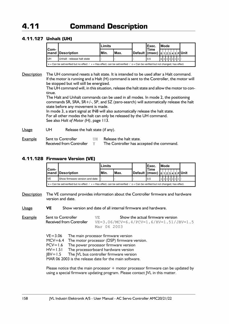
158 JVL Industri Elektronik A/S - User Manual - AC Servo Controller AMC20/21/22
4.11 Command Description
4.11.127 Unhalt (UH)
Description The UH command resets a halt state. It is intended to be used after a Halt command.If the motor is running and a Halt (H) command is sent to the Controller, the motor will be stopped but will still be energized.The UH command will, in this situation, release the halt state and allow the motor to con-tinue.The Halt and Unhalt commands can be used in all modes. In mode 2, the positioning commands SR, SRA, SR+/-, SP, and SZ (zero-search) will automatically release the halt state before any movement is made.In mode 3, a start signal at IN8 will also automatically release the halt state.For all other modes the halt can only be released by the UH command.See also Halt of Motor (H), page 113.
Usage UH Release the halt state (if any).
Example Sent to Controller UH Release the halt state.Received from Controller Y The Controller has accepted the command.
4.11.128 Firmware Version (VE)
Description The VE command provides information about the Controller firmware and hardware version and date.
Usage VE Show version and date of all internal firmware and hardware.
Example Sent to Controller VE Show the actual firmware versionReceived from Controller VE=3.06/MCV=6.4/PCV=1.6/HV=1.51/JBV=1.5
Mar 06 2003
VE=3.06 The main processor firmware versionMCV=6.4 The motor processor (DSP) firmware version.PCV=1.6 The power processor firmware versionHV=1.51 The processorboard hardware versionJBV=1.5 The JVL bus controller firmware versionMAR 06 2003 is the release date for the main software.
Please notice that the main processor + motor processor firmware can be updated by using a special firmware updating program. Please contact JVL in this matter.
Com-mand Description
Limits
Default
Exec.Time(msec)
Mode
UnitMin. Max. 0 1 2 3 4 5 P
UH Unhalt - release halt state - - - 0.5 x + + + + + + -
x = Can be set/verified but no effect / + = Has effect, can be set/verified / o = Can be verified but not changed, has effect.
Com-mand Description
Limits
Default
Exec.Time(msec)
Mode
UnitMin. Max. 0 1 2 3 4 5 P
VE Show firmware version and date - - - 0.5 + + + + + + + -
x = Can be set/verified but no effect / + = Has effect, can be set/verified / o = Can be verified but not changed, has effect.
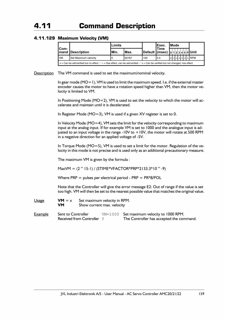
JVL Industri Elektronik A/S - User Manual - AC Servo Controller AMC20/21/22 159
4.11 Command Description
4.11.129 Maximum Velocity (VM)
Description The VM command is used to set the maximum/nominal velocity.
In gear mode (MO=1), VM is used to limit the maximum speed. I.e. if the external master encoder causes the motor to have a rotation speed higher than VM, then the motor ve-locity is limited to VM.
In Positioning Mode (MO=2), VM is used to set the velocity to which the motor will ac-celerate and maintain until it is decelerated.
In Register Mode (MO=3), VM is used if a given XV register is set to 0.
In Velocity Mode (MO=4), VM sets the limit for the velocity corresponding to maximum input at the analog input. If for example VM is set to 1000 and the analogue input is ad-justed to an input voltage in the range -10V to +10V, the motor will rotate at 500 RPM in a negative direction for an applied voltage of -5V.
In Torque Mode (MO=5), VM is used to set a limit for the motor. Regulation of the ve-locity in this mode is not precise and is used only as an additional precautionary measure.
The maximum VM is given by the formula :
MaxVM = (2^15-1) / (STIME*VFACTOR*PRP*2133.3*10^-9)
Where PRP = pulses per electrical period - PRP = PR*8/POL
Note that the Controller will give the error message E2: Out of range if the value is set too high. VM will then be set to the nearest possible value that matches the original value.
Usage VM = x Set maximum velocity in RPM.VM Show current max. velocity
Example Sent to Controller VM=1000 Set maximum velocity to 1000 RPM.Received from Controller Y The Controller has accepted the command.
Com-mand Description
Limits
Default
Exec.Time(msec)
Mode
UnitMin. Max. 0 1 2 3 4 5 P
VM Set Maximum velocity 0 32767 100 0.5 x + + + + + + RPM
x = Can be set/verified but no effect / + = Has effect, can be set/verified / o = Can be verified but not changed, has effect.
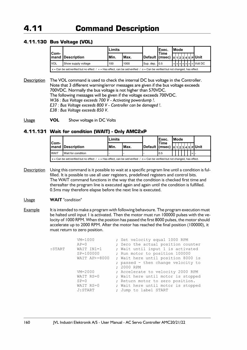
160 JVL Industri Elektronik A/S - User Manual - AC Servo Controller AMC20/21/22
4.11 Command Description
4.11.130 Bus Voltage (VOL)
Description The VOL command is used to check the internal DC bus voltage in the Controller.Note that 3 different warning/error messages are given if the bus voltage exceeds 700VDC. Normally the bus voltage is not higher than 570VDC.The following messages will be given if the voltage exceeds 700VDC.W36 : Bus Voltage exceeds 700 V - Activating powerdump !.E37 : Bus Voltage exceeds 800 V - Controller can be damaged !.E38 : Bus Voltage exceeds 850 V.
Usage VOL Show voltage in DC Volts
4.11.131 Wait for condition (WAIT) - Only AMC2xP
Description Using this command is it possible to wait at a specific program line until a condition is ful-filled. It is possible to use all user registers, predefined registers and control bits.The WAIT command functions in the way that the condition is checked first time and thereafter the program line is executed again and again until the condition is fulfilled. 0.5ms may therefore elapse before the next line is executed.
Usage WAIT "condition"
Example It is intended to make a program with following behavoure. The program execution must be halted until input 1 is activated. Then the motor must run 100000 pulses with the ve-locity of 1000 RPM. When the position has passed the first 8000 pulses, the motor should accelerate up to 2000 RPM. After the motor has reached the final position (100000), it must return to zero position.
VM=1000 ; Set velocity equal 1000 RPMAP=0 ; Zero the actual position counter
:START WAIT IN1=1 ; Wait until input 1 is activatedSP=100000 ; Run motor to position 100000 WAIT AP>=8000 ; Wait here until position 8000 is
; passed - then change velocity to ; 2000 RPM
VM=2000 ; Accelerate to velocity 2000 RPMWAIT RS=0 ; Wait here until motor is stoppedSP=0 ; Return motor to zero position.WAIT RS=0 ; Wait here until motor is stoppedJ:START ; Jump to label START
Com-mand Description
Limits
Default
Exec.Time(msec)
Mode
UnitMin. Max. 0 1 2 3 4 5 P
VOL Show supply voltage 100 1000 Sup. dep. 0.5 + + + + + + + Volt DC
x = Can be set/verified but no effect / + = Has effect, can be set/verified / o = Can be verified but not changed, has effect.
Com-mand Description
Limits
Default
Exec.Time(msec)
Mode
UnitMin. Max. 0 1 2 3 4 5 P
WAIT Wait for condition - - - 0.5 + -
x = Can be set/verified but no effect / + = Has effect, can be set/verified / o = Can be verified but not changed, has effect.
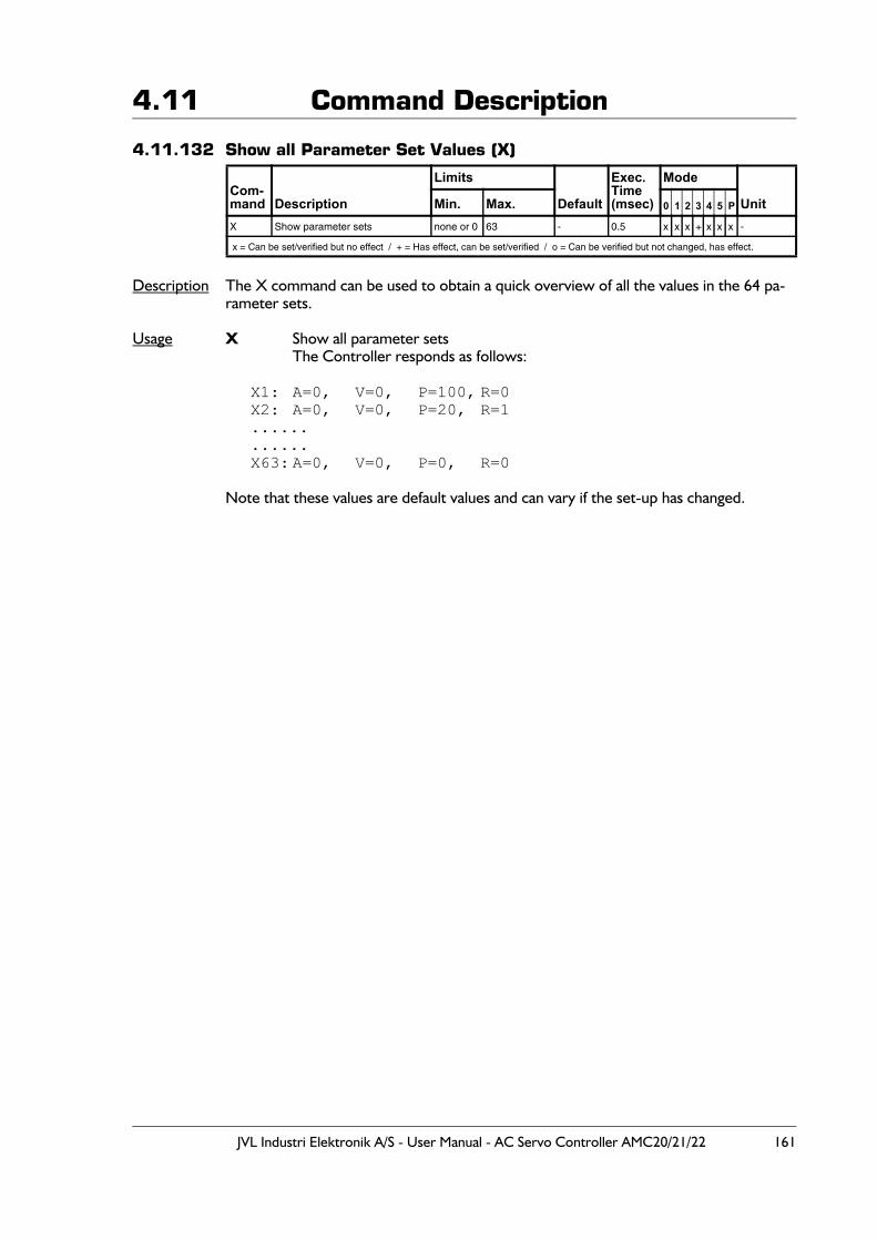
JVL Industri Elektronik A/S - User Manual - AC Servo Controller AMC20/21/22 161
4.11 Command Description
4.11.132 Show all Parameter Set Values (X)
Description The X command can be used to obtain a quick overview of all the values in the 64 pa-rameter sets.
Usage X Show all parameter setsThe Controller responds as follows:
X1: A=0, V=0, P=100, R=0X2: A=0, V=0, P=20, R=1............X63: A=0, V=0, P=0, R=0
Note that these values are default values and can vary if the set-up has changed.
Com-mand Description
Limits
Default
Exec.Time(msec)
Mode
UnitMin. Max. 0 1 2 3 4 5 P
X Show parameter sets none or 0 63 - 0.5 x x x + x x x -
x = Can be set/verified but no effect / + = Has effect, can be set/verified / o = Can be verified but not changed, has effect.
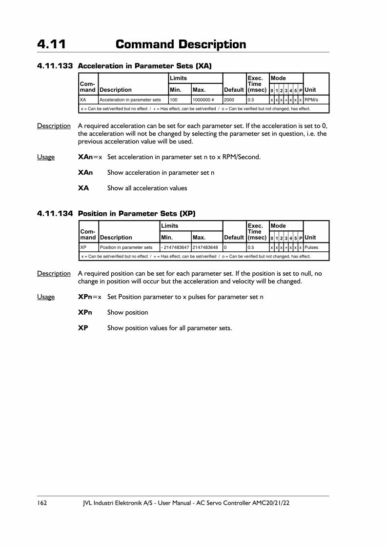
162 JVL Industri Elektronik A/S - User Manual - AC Servo Controller AMC20/21/22
4.11 Command Description
4.11.133 Acceleration in Parameter Sets (XA)
Description A required acceleration can be set for each parameter set. If the acceleration is set to 0, the acceleration will not be changed by selecting the parameter set in question, i.e. the previous acceleration value will be used.
Usage XAn=x Set acceleration in parameter set n to x RPM/Second.
XAn Show acceleration in parameter set n
XA Show all acceleration values
4.11.134 Position in Parameter Sets (XP)
Description A required position can be set for each parameter set. If the position is set to null, no change in position will occur but the acceleration and velocity will be changed.
Usage XPn=x Set Position parameter to x pulses for parameter set n
XPn Show position
XP Show position values for all parameter sets.
Com-mand Description
Limits
Default
Exec.Time(msec)
Mode
UnitMin. Max. 0 1 2 3 4 5 P
XA Acceleration in parameter sets 100 1000000 # 2000 0.5 x x x + x x x RPM/s
x = Can be set/verified but no effect / + = Has effect, can be set/verified / o = Can be verified but not changed, has effect.
Com-mand Description
Limits
Default
Exec.Time(msec)
Mode
UnitMin. Max. 0 1 2 3 4 5 P
XP Position in parameter sets - 2147483647 2147483648 0 0.5 x x x + x x x Pulses
x = Can be set/verified but no effect / + = Has effect, can be set/verified / o = Can be verified but not changed, has effect.
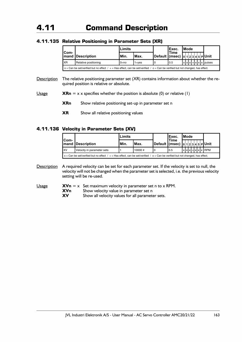
JVL Industri Elektronik A/S - User Manual - AC Servo Controller AMC20/21/22 163
4.11 Command Description
4.11.135 Relative Positioning in Parameter Sets (XR)
Description The relative positioning parameter set (XR) contains information about whether the re-quired position is relative or absolute.
Usage XRn = x x specifies whether the position is absolute (0) or relative (1)
XRn Show relative positioning set-up in parameter set n
XR Show all relative positioning values
4.11.136 Velocity in Parameter Sets (XV)
Description A required velocity can be set for each parameter set. If the velocity is set to null, the velocity will not be changed when the parameter set is selected, i.e. the previous velocity setting will be re-used.
Usage XVn = x Set maximum velocity in parameter set n to x RPM.XVn Show velocity value in parameter set n XV Show all velocity values for all parameter sets.
Com-mand Description
Limits
Default
Exec.Time(msec)
Mode
UnitMin. Max. 0 1 2 3 4 5 P
XR Relative positioning 0=no 1=yes 0 0.5 x x x + x x x pulses
x = Can be set/verified but no effect / + = Has effect, can be set/verified / o = Can be verified but not changed, has effect.
Com-mand Description
Limits
Default
Exec.Time(msec)
Mode
UnitMin. Max. 0 1 2 3 4 5 P
XV Velocity in parameter sets 1 10000 # 0 0.5 x x x + x x x RPM
x = Can be set/verified but no effect / + = Has effect, can be set/verified / o = Can be verified but not changed, has effect.
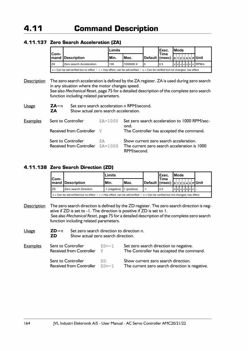
164 JVL Industri Elektronik A/S - User Manual - AC Servo Controller AMC20/21/22
4.11 Command Description
4.11.137 Zero Search Acceleration (ZA)
Description The zero search acceleration is defined by the ZA register. ZA is used during zero search in any situation where the motor changes speed.See also Mechanical Reset, page 75 for a detailed description of the complete zero search function including related parameters.
Usage ZA=n Set zero search acceleration n RPM/second.ZA Show actual zero search acceleration.
Examples Sent to Controller ZA=1000 Set zero search acceleration to 1000 RPM/sec-ond.
Received from Controller Y The Controller has accepted the command.
Sent to Controller ZA Show current zero search acceleration.Received from Controller ZA=1000 The current zero search acceleration is 1000
RPM/second.
4.11.138 Zero Search Direction (ZD)
Description The zero search direction is defined by the ZD register. The zero search direction is neg-ative if ZD is set to -1. The direction is positive if ZD is set to 1. See also Mechanical Reset, page 75 for a detailed description of the complete zero search function including related parameters.
Usage ZD=n Set zero search direction to direction n.ZD Show actual zero search direction.
Examples Sent to Controller ZD=-1 Set zero search direction to negative.Received from Controller Y The Controller has accepted the command.
Sent to Controller ZD Show current zero search direction.Received from Controller ZD=-1 The current zero search direction is negative.
Com-mand Description
Limits
Default
Exec.Time(msec)
Mode
UnitMin. Max. 0 1 2 3 4 5 P
ZA Zero search Acceleration 100 1000000 # 0 0.5 x x + + x x x RPM/s
x = Can be set/verified but no effect / + = Has effect, can be set/verified / o = Can be verified but not changed, has effect.
Com-mand Description
Limits
Default
Exec.Time(msec)
Mode
UnitMin. Max. 0 1 2 3 4 5 P
ZD Zero search Direction -1 (negative) 1 (positive) -1 0.5 x x + + x x x -
x = Can be set/verified but no effect / + = Has effect, can be set/verified / o = Can be verified but not changed, has effect.
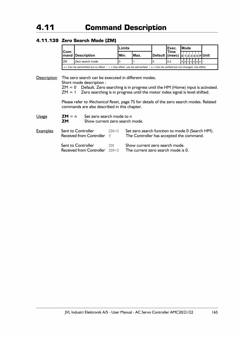
JVL Industri Elektronik A/S - User Manual - AC Servo Controller AMC20/21/22 165
4.11 Command Description
4.11.139 Zero Search Mode (ZM)
Description The zero search can be executed in different modes.Short mode description :ZM = 0 Default. Zero searching is in progress until the HM (Home) input is activated.ZM = 1 Zero searching is in progress until the motor index signal is level shifted.
Please refer to Mechanical Reset, page 75 for details of the zero search modes. Related commands are also described in this chapter.
Usage ZM = n Set zero search mode to nZM Show current zero search mode.
Examples Sent to Controller ZM=0 Set zero search function to mode 0 (Search HM).Received from Controller Y The Controller has accepted the command.
Sent to Controller ZM Show current zero search mode.Received from Controller ZM=0 The current zero search mode is 0.
Com-mand Description
Limits
Default
Exec.Time(msec)
Mode
UnitMin. Max. 0 1 2 3 4 5 P
ZM Zero search mode 0 1 0 0.5 x x + + x x x -
x = Can be set/verified but no effect / + = Has effect, can be set/verified / o = Can be verified but not changed, has effect.
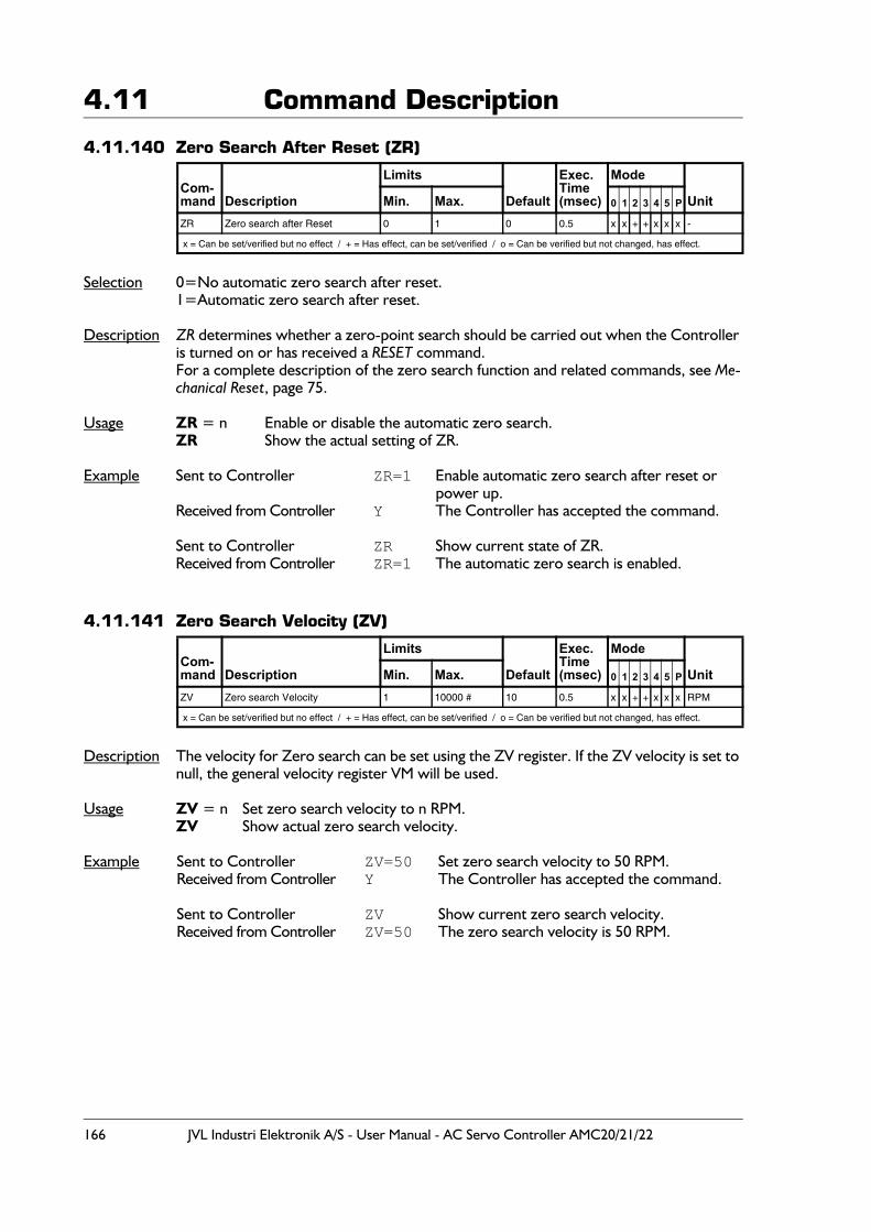
166 JVL Industri Elektronik A/S - User Manual - AC Servo Controller AMC20/21/22
4.11 Command Description
4.11.140 Zero Search After Reset (ZR)
Selection 0=No automatic zero search after reset.1=Automatic zero search after reset.
Description ZR determines whether a zero-point search should be carried out when the Controller is turned on or has received a RESET command.For a complete description of the zero search function and related commands, see Me-chanical Reset, page 75.
Usage ZR = n Enable or disable the automatic zero search.ZR Show the actual setting of ZR.
Example Sent to Controller ZR=1 Enable automatic zero search after reset or power up.
Received from Controller Y The Controller has accepted the command.
Sent to Controller ZR Show current state of ZR.Received from Controller ZR=1 The automatic zero search is enabled.
4.11.141 Zero Search Velocity (ZV)
Description The velocity for Zero search can be set using the ZV register. If the ZV velocity is set to null, the general velocity register VM will be used.
Usage ZV = n Set zero search velocity to n RPM.ZV Show actual zero search velocity.
Example Sent to Controller ZV=50 Set zero search velocity to 50 RPM.Received from Controller Y The Controller has accepted the command.
Sent to Controller ZV Show current zero search velocity.Received from Controller ZV=50 The zero search velocity is 50 RPM.
Com-mand Description
Limits
Default
Exec.Time(msec)
Mode
UnitMin. Max. 0 1 2 3 4 5 P
ZR Zero search after Reset 0 1 0 0.5 x x + + x x x -
x = Can be set/verified but no effect / + = Has effect, can be set/verified / o = Can be verified but not changed, has effect.
Com-mand Description
Limits
Default
Exec.Time(msec)
Mode
UnitMin. Max. 0 1 2 3 4 5 P
ZV Zero search Velocity 1 10000 # 10 0.5 x x + + x x x RPM
x = Can be set/verified but no effect / + = Has effect, can be set/verified / o = Can be verified but not changed, has effect.
JVL Industri Elektronik A/S - User Manual - AC Servo Controller AMC20/21/22 167
4.12 Error Messages
When an error occurs in communication with the Controller or when an internal error occurs, the Controller transmits an error message. The error message consists of an ‘E’, followed by an error number, followed by a colon ‘:’, followed by a descriptive English text. The following illustrates an example of an error message:
Example: E2: Out of range
The error messages can be read by typing "EST (enter)" in the on-line editor in Moto-Ware. When a old message is read once, it will be deleted from the error register and not shown again.
4.12.1 Description of Error Messages
E0: No errorsNo errors have occurred since the last request.
E1: ErrorThe command string cannot be understood.Example:
asdfælkj (enter)Results in error E1.
Correction:Carefully check the command sent to Controller and compare with the description of the command given in this manual.
E2: Out of rangeThe parameter value specified with the command is out of the allowable range.Example:
CP=100The above command attempts to set the peak current to 100 Amps, which is outside the allowable range. The Controller therefore reports an E2 error.
Correction:Specify a parameter value within the allowable range for the actual command.
E3: Number of parameters is wrongThe number of parameters specified with the command is incorrect.Example:
VM100 or ES0=9Both of the above command examples will produce an E3 error.
Correction:The VM command has only 1 register associated with it and can therefore only be called by specifying VM. Correction : send the command VM=100.The ESO command is only used to show information and therefore specifying a pa-rameter has no meaning.
E4: Instruction does not existThe command does not exist.Example:
ABCDEFCorrection:
Use a valid Controller command. See the description of the command for details of the required command syntax.
168 JVL Industri Elektronik A/S - User Manual - AC Servo Controller AMC20/21/22
4.12 Error Messages
E5: It is not an instructionThe Controller has not received a proper command.Example:
4RIf the Controller is not using addressing, this example will result in error E5.
Correction:Use a proper command.
E6: Parameter error or out of rangeThere is an error in the specified parameter or the parameter value is out of the allowable range.Example:
SP=111111111111 or VM=8G7Correction:
The Controller cannot handle values as great as 111111111111 in the first example. Use a value within the allowable range.In the second example: parameter values must not contain alphabetic characters.
E7: Register number error or out of rangeError in register number.Example:
XP7777 or XP4FCorrection:
In the first example: use a register number in the allowable range.In the second example: register number must not contain alphabetic characters.
E8: Data can not be stored in FLASHPROMThe set-up cannot be stored in the FLASHPROM. A hardware error has occurred that prevents the CPU from communicating with FLASHPROM.Correction:
Try to restart the Controller by shutting off the power.Try to set Controller to default by typing SD followed by MS. Restart Controller.
E9: Checksum errorThe Controller’s (receiver’s) calculated checksum is not the same as the transmitted checksum. Example:
255KP=25F3Correction:
Send the command as 255KP=25DB.
W10: Parameter will be roundedThe Controller has received a parameter value which must be an integer. Example:
VM=1000.8Correction:
Send the command specifying an integer value VM=1000 or VM=1001.
Example:The calculation R1=5 / 2 will cause the W10 warning to appear since R1 will be rounded to 2.
JVL Industri Elektronik A/S - User Manual - AC Servo Controller AMC20/21/22 169
4.12 Error MessagesE11: No Program availableThere is no program in the program (RAM) memory. Example:
After executing a GO command, the E11: No Program available will appearif there is no program in the program memory.
Correction:Use MR to retrieve the program from FLASHPROM or enter a new program.
E12: Zero Search Function ActiveThe zero search function is already active. The motor is moving while the Controller is waiting for a signal at the HM input or other signal (depending on ZM - zero search mode register)Example:
An SZ command (start zero search) is sent but the zero search is already in progress.Correction:
Avoid starting a zero search when a zero search is already in progress.
E13: Command not valid in this modeThe Controller is setup in a mode (Mode register) where the use of the chosen com-mand or register is not possible.Example:
The SP command (set position) is used in mode 5 (torque mode). This is not possiblebecause mode 5 is only intended for torque control and not position control.
Correction:Set the Controller in position mode (MO=2) and send the SP command.
E14: Not allowed due to previous fatal errorThe Controller is in a fatal error state, which typically means that the motor is not able to make any movements. This state is typically provoked by too high an average current or a following error, but other circumstances can also be the reason. Verify the other messages in the error register to determine the exact cause of the fatal error state.Example:
The average current during normal operation has been too high and the Controller is set in mode 0. If a positioning command is used, such as SP=xxx, the Controller will return the E14: Not allowed due to previous fatal error.
Correction:Only a RESET or power down of the Controller will cancel the fatal error and there-by allow the actual command to be executed.
E15: Error initialising motorThe Controller has tried to initialise the motor but for some reason this was not possible.The problem can be one of following.1. The INITTYPE is set to 0 (fixed field initialisation) but during initialization the motor
was unstable. The commutation angle could not be found.2. The INITTYPE is set to 1 (mixed field initialisation). This is a future option not sup-
ported. The initialization is therefore cancelled.3. The INITTYPE is set to 2 (hall initialisation) but the HALL register is not adjusted for
the right Hall sensor.
Correction:Check the motor and feedback (encoder/hall) connections and consult the Initialisa-tion Type (INITTYPE), page 122 or Hall-element Type (HALL), page 114 to ensure the correct setting.
170 JVL Industri Elektronik A/S - User Manual - AC Servo Controller AMC20/21/22
4.12 Error Messages
E32: Check Other Status RegisterAn error has been detected in one of the other status registers. Read register ES0, ES1, ES2 or ES3. This error message can appear while reading one of these registers.
E33: Current Overload - Motor short-circuitedThe Controller has been overloaded/short-circuited.Correction:
Use another motor or insert an inductance of approximately 1mH in series with the motor leads. The inductances must be placed in the FA, FB, FC leads.This error can also appear if the current loop has been faultily tuned. Try a new auto-tuning. Remember to tune using a realistic mains voltage.
E34 : Power consumption too highThe Controller/motor has been drawing too much power from the supply.This limit is set by the PM command.Correction:
Decrease the motor speed / load or increase the value of the PM register.See also Power Management (PM), page 140
E35 : Average Current limit exceededThe maximum allowable average current has been exceeded.Example:
The velocity or load is very high or the CA (average current) register is not set cor-rect for the actual motor.
Correction:Reduce velocity or load until the error disappears. Check that CA is set correctly.
W36 : Bus Voltage exceeds 700 V - Activating powerdump !The power Bus voltage has exceeded 700V. This is only a warning. Under normal oper-ation this can happen if the motor decelerates with a high inertia causing a lot of energy to flow back from the motor to the Controller and thereby increasing the bus voltage.Example:
The power supply voltage is too high or the motor has been decelerated quickly with a high inertial load.
Correction:If the supply voltage is too high, it should be reduced. During deceleration the motor can send current back to the Controller, causing the bus voltage to increase. The deceleration (AC) can be reduced until the error dis-appears. If required, a “Power Dump” shunt resistor should be inserted as de-scribed in Power Dump Output, page 42. If deceleration must be rapid, this warning is ok.
E37 : Bus Voltage exceeds 800 V - Controller can be damaged !The power Bus voltage has exceeded 800V. This is an error that indicates that the power dump circuitry is not able to consume the extra amount of energy that flows back from the motor to the Controller, thereby increasing the bus voltage. This energy is typically caused by high inertial load on the motor which makes the internal supply increase if the deceleration of the motor is rapid. This error is number 2 of 3. See also W36 : Bus Voltage exceeds 700 V - Activating powerdump ! or E38 : Bus Voltage exceeds 850 V. Note that if the voltage reaches 850V, the Controller will shut down the driver circuit and therefore make the motor currentless.Correction:
Decrease the deceleration (AC) until the error disappears. If required, a “Power Dump” shunt resistor should be inserted as described in Power Dump Output, page 42.
JVL Industri Elektronik A/S - User Manual - AC Servo Controller AMC20/21/22 171
4.12 Error MessagesE38 : Bus Voltage exceeds 850 VThe Bus voltage has exceeded 850V. Important ! : This error message can be fatal since too high a voltage can damage the
power circuitry inside the Controller.Example:
The power supply voltage is too high or the motor is being decelerated too quickly.Correction:
If the power supply voltage is too high, it must be reduced.During deceleration the motor can send current back to the Controller, causing an increase in the bus voltage. The deceleration (AC) must be reduced until the error disappears. The problem can also be alleviated by using a “Power Dump” shunt re-sistor. See Power Dump Output, page 42.
E39 : The motor is not mounted correctlyThe motor is not connected correctly.Example:
The motor is moving in the wrong direction.Correction:
Read the section dealing with motor connections see Motor Connection, page 27.
E40 : The motor is not connectedThe motor is not connected.Example:
The motor does not move.Correction:
Check the motor connections.
E41 : HALL element is not connected properlyThe Hall element’s signals are not connected or are faulty.Correction:
Check the Hall element connections and check that the Hall register and HL are ad-justed correctly. If operation without the use of a Hall element is required, the Hall register is set to 0 (normal). See Hall-element Type (HALL), page 114
W42 : Temperature exceeded 75°C.This is only a warning. The temperature inside the Controller has exceeded 75°C.The Controller will continue to function normally, but if the temperature exceeds 85°C, the Controller’s thermal overload protection will prevent damage by setting the power section to standby, which means that the motor will be current less. The T>75°C LED on the front of the Controller will be lit.Correction:
- Reduce the ambient temperature or reduce load at the motor.- Consider to decrease the PWM frequency to 5KHz - see CB2 - Set low PWM out-
put frequency, page 92.- If the W36 : Bus Voltage exceeds 700 V - Activating powerdump ! is often shown it
indicates that the internal power dump resistor is often used. Consider to mount an external power dump in order to decrease the internal heat in the controller.
172 JVL Industri Elektronik A/S - User Manual - AC Servo Controller AMC20/21/22
4.12 Error MessagesE43 : Temperature exceeded 85°CThe temperature inside the Controller has exceeded 85°C. The Controller will prevent internal damage by setting the power section to standby, which means that the motor will be current less. Correction:
- Reduce the ambient temperature or reduce load at the motor.- Consider to decrease the PWM frequency to 5KHz - see CB2 - Set low PWM output
frequency, page 92.- If the W36 : Bus Voltage exceeds 700 V - Activating powerdump ! is often shown it
indicates that the internal power dump resistor is often used. Consider to mount an external power dump in order to decrease the internal heat in the controller.
E44 : Bus current exceeds plus 10AThe current at the internal DC bus has exceed +10A RMS which means that the energy flowing is too high. This can be caused by too high an inertial load on the motor or too high deceleration.Correction:
The deceleration (AC) can be reduced until the error disappears.The load inertia at the motor must be decreased.
E45 : Bus current exceeds minus 10AThe current at the internal DC bus has exceed -10A RMS which means that the energy flowing is too high. This can be caused by too high an inertial on the motor or too high acceleration.Correction:
The acceleration (AC) can be reduced until the error disappears.The load inertia at the motor must be decreased.
E46 : Overload on output portsThe user outputs (O1-O8) have been overloaded. The overload can be caused by an overload on one or more of the outputs. An overload occurs if an output is short circuited or too high a current is drawn (>700mA).Correction:
Check that no short-circuit exists between an output and ground (O-).Check that the current at each of the 8 outputs (O1-O8) does not exceed 700mA at any time, also during an activation if the load is capacitive.
E47: Bus voltage too lowThe voltage at the internal DC-bus is too low.This may be caused by too low a voltage at the supply terminals U1, V1, or W1, or if the Controller is supplied by a single-phase supply, the total power consumption of the mo-tor is so high that the internal DC-voltage sometimes drops below 100VDC.Correction:
- Check that the mains supply fulfils the voltage requirements listed in Technical Data, page 182.
- If only a single-phase supply is used as the mains supply, consider using a 3-phase supply. However, ensure that the actual motor is rated for the higher voltage which will be present when using 3 supply phases instead of a single phase.
- See: Power Supply, page 25 for details.
JVL Industri Elektronik A/S - User Manual - AC Servo Controller AMC20/21/22 173
4.12 Error MessagesE48: Error initializing motorThe controller have not been able to determine the position of the motor (rotor) after power up or an initialization. A typical error source is the Hall signals. If an invalid code on this signals appears the E48 message will be shown. The error message only appears when an active mode is selected (Mode 1 to 5).Correction:
Check the Hall/Encoder cables or verify that the Hall setup is done correct. See also Setting the Hall Element, page 196
E49: Serial Encoder failedThis message only apears if a serial encoder is used. The message indicates that the serial communication with the encoder could not be established.Correction:
Check the encoder cable and make sure that the right encoder type is chosen. See also Encoder Type (ET), page 110.
E50: Currentfilter overflowThe current filter has not been able to control the motor current within the range that that the controller can handle. The maximum peak current has been exceeded.Correction:
Lower the acceleration or deceleration.Try to reoptimize the current filter with a higher bandwidth. See also Current filter optimizing, page 16
E51 - 63: Reserved for future use
E65 : Motor controller Communication errorInternal error. The main processor is not able to communicate with the motor processor (DSP) that takes care of the motor and servo filter.Correction:
Turn off power immediately and consult JVL.
E66 : Power processor TimeoutInternal error. The main processor is not able to communicate with the power processor that takes care of the driver section including power supply.Correction:
Turn off power immediately and consult JVL.
E67 : Unknown error from Power processorInternal error. The main processor is not able to communicate with the power proces-sor that takes care of the driver section including power supply.Correction:
Turn off power immediately and consult JVL.
E68 : Average current cannot be measured correctlyThe average current value in the motor phases cannot be measured correctly.Correction:
Turn the Controller off and then on again. If the error condition persists, a hardware error has occurred. It is important to note that the motor must not be moving when the Controller is switched on.
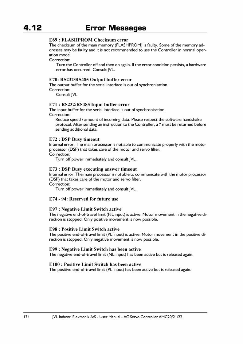
174 JVL Industri Elektronik A/S - User Manual - AC Servo Controller AMC20/21/22
4.12 Error MessagesE69 : FLASHPROM Checksum errorThe checksum of the main memory (FLASHPROM) is faulty. Some of the memory ad-dresses may be faulty and it is not recommended to use the Controller in normal oper-ation mode.Correction:
Turn the Controller off and then on again. If the error condition persists, a hardware error has occurred. Consult JVL.
E70: RS232/RS485 Output buffer errorThe output buffer for the serial interface is out of synchronisation.Correction:
Consult JVL.
E71 : RS232/RS485 Input buffer errorThe input buffer for the serial interface is out of synchronisation.Correction:
Reduce speed / amount of incoming data. Please respect the software handshake protocol. After sending an instruction to the Controller, a Y must be returned before sending additional data.
E72 : DSP Busy timeoutInternal error. The main processor is not able to communicate properly with the motor processor (DSP) that takes care of the motor and servo filter.Correction:
Turn off power immediately and consult JVL.
E73 : DSP Busy executing answer timeoutInternal error. The main processor is not able to communicate with the motor processor (DSP) that takes care of the motor and servo filter.Correction:
Turn off power immediately and consult JVL.
E74 - 94: Reserved for future use
E97 : Negative Limit Switch activeThe negative end-of-travel limit (NL input) is active. Motor movement in the negative di-rection is stopped. Only positive movement is now possible.
E98 : Positive Limit Switch activeThe positive end-of-travel limit (PL input) is active. Motor movement in the positive di-rection is stopped. Only negative movement is now possible.
E99 : Negative Limit Switch has been activeThe negative end-of-travel limit (NL input) has been active but is released again.
E100 : Positive Limit Switch has been activeThe positive end-of-travel limit (PL input) has been active but is released again.
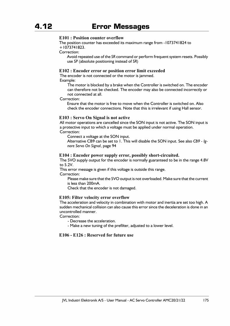
JVL Industri Elektronik A/S - User Manual - AC Servo Controller AMC20/21/22 175
4.12 Error MessagesE101 : Position counter overflowThe position counter has exceeded its maximum range from -1073741824 to +1073741823.Correction:
Avoid repeated use of the SR command or perform frequent system resets. Possibly use SP (absolute positioning instead of SR)
E102 : Encoder error or position error limit exceededThe encoder is not connected or the motor is jammed.Example:
The motor is blocked by a brake when the Controller is switched on. The encoder can therefore not be checked. The encoder may also be connected incorrectly or not connected at all.
Correction:Ensure that the motor is free to move when the Controller is switched on. Also check the encoder connections. Note that this is irrelevant if using Hall sensor.
E103 : Servo On Signal is not activeAll motor operations are cancelled since the SON input is not active. The SON input is a protective input to which a voltage must be applied under normal operation.Correction:
Connect a voltage at the SON input.Alternative CB9 can be set to 1. This will disable the SON input. See also CB9 - Ig-nore Servo On Signal, page 94
E104 : Encoder power supply error, possibly short-circuited.The 5VO supply output for the encoder is normally guaranteed to be in the range 4.8Vto 5.2V.This error message is given if this voltage is outside this range.Correction:
Please make sure that the 5VO output is not overloaded. Make sure that the current is less than 200mA.Check that the encoder is not damaged.
E105: Filter velocity error overflowThe acceleration and velocity in combination with motor and inertia are set too high. A sudden mechanical collision can also cause this error since the deceleration is done in an uncontrolled manner.Correction:
- Decrease the acceleration.- Make a new tuning of the prefilter, adjusted to a lower level.
E106 - E126 : Reserved for future use
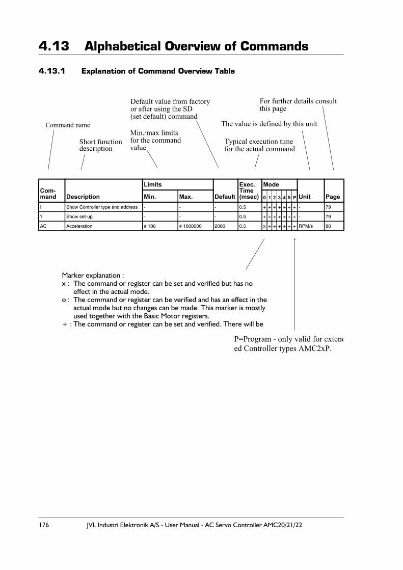
176 JVL Industri Elektronik A/S - User Manual - AC Servo Controller AMC20/21/22
4.13 Alphabetical Overview of Commands
4.13.1 Explanation of Command Overview Table
Com-mand Description
Limits
Default
Exec.Time(msec)
Mode
Unit PageMin. Max. 0 1 2 3 4 5 P
! Show Controller type and address - - - 0.5 + + + + + + + - 79
? Show set-up - - - 0.5 + + + + + + + - 79
AC Acceleration # 100 # 1000000 2000 0.5 x + + + + + + RPM/s 80
Command name
Short functiondescription
Min./max limitsfor the commandvalue
Default value from factoryor after using the SD(set default) command
Typical execution timefor the actual command
For further details consultthis page
The value is defined by this unit
Marker explanation :x : The command or register can be set and verified but has no
effect in the actual mode.o : The command or register can be verified and has an effect in the
actual mode but no changes can be made. This marker is mostlyused together with the Basic Motor registers.
+ : The command or register can be set and verified. There will be
P=Program - only valid for extended Controller types AMC2xP.
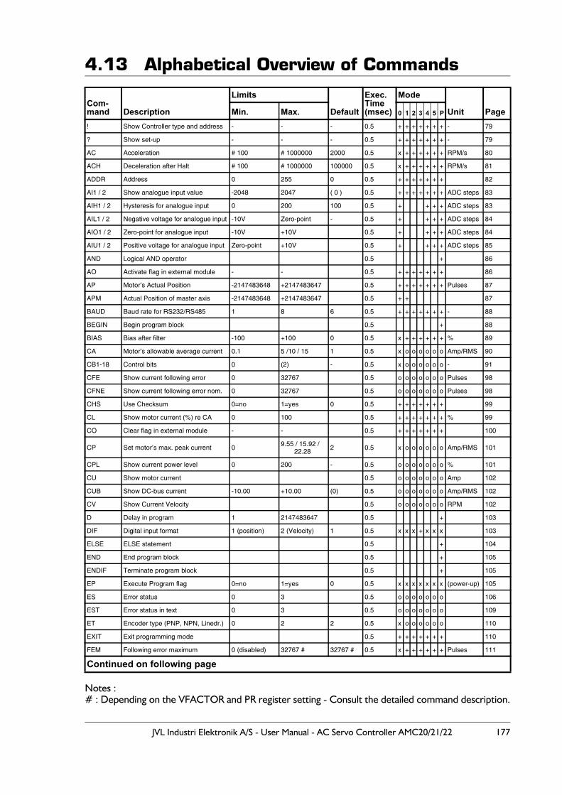
JVL Industri Elektronik A/S - User Manual - AC Servo Controller AMC20/21/22 177
4.13 Alphabetical Overview of Commands
Notes :# : Depending on the VFACTOR and PR register setting - Consult the detailed command description.
Com-mand Description
Limits
Default
Exec.Time(msec)
Mode
Unit PageMin. Max. 0 1 2 3 4 5 P
! Show Controller type and address - - - 0.5 + + + + + + + - 79
? Show set-up - - - 0.5 + + + + + + + - 79
AC Acceleration # 100 # 1000000 2000 0.5 x + + + + + + RPM/s 80
ACH Deceleration after Halt # 100 # 1000000 100000 0.5 x + + + + + + RPM/s 81
ADDR Address 0 255 0 0.5 + + + + + + + 82
AI1 / 2 Show analogue input value -2048 2047 ( 0 ) 0.5 + + + + + + + ADC steps 83
AIH1 / 2 Hysteresis for analogue input 0 200 100 0.5 + + + + ADC steps 83
AIL1 / 2 Negative voltage for analogue input -10V Zero-point - 0.5 + + + + ADC steps 84
AIO1 / 2 Zero-point for analogue input -10V +10V 0.5 + + + + ADC steps 84
AIU1 / 2 Positive voltage for analogue input Zero-point +10V 0.5 + + + + ADC steps 85
AND Logical AND operator 0.5 + 86
AO Activate flag in external module - - 0.5 + + + + + + + 86
AP Motor’s Actual Position -2147483648 +2147483647 0.5 + + + + + + + Pulses 87
APM Actual Position of master axis -2147483648 +2147483647 0.5 + + 87
BAUD Baud rate for RS232/RS485 1 8 6 0.5 + + + + + + + - 88
BEGIN Begin program block 0.5 + 88
BIAS Bias after filter -100 +100 0 0.5 x + + + + + + % 89
CA Motor’s allowable average current 0.1 5 /10 / 15 1 0.5 x o o o o o o Amp/RMS 90
CB1-18 Control bits 0 (2) - 0.5 x o o o o o o - 91
CFE Show current following error 0 32767 0.5 o o o o o o o Pulses 98
CFNE Show current following error nom. 0 32767 0.5 o o o o o o o Pulses 98
CHS Use Checksum 0=no 1=yes 0 0.5 + + + + + + + 99
CL Show motor current (%) re CA 0 100 0.5 + + + + + + + % 99
CO Clear flag in external module - - 0.5 + + + + + + + 100
CP Set motor’s max. peak current 0 9.55 / 15.92 /22.28 2 0.5 x o o o o o o Amp/RMS 101
CPL Show current power level 0 200 - 0.5 o o o o o o o % 101
CU Show motor current 0.5 o o o o o o o Amp 102
CUB Show DC-bus current -10.00 +10.00 (0) 0.5 o o o o o o o Amp/RMS 102
CV Show Current Velocity 0.5 o o o o o o o RPM 102
D Delay in program 1 2147483647 0.5 + 103
DIF Digital input format 1 (position) 2 (Velocity) 1 0.5 x x x + x x x 103
ELSE ELSE statement 0.5 + 104
END End program block 0.5 + 105
ENDIF Terminate program block 0.5 + 105
EP Execute Program flag 0=no 1=yes 0 0.5 x x x x x x x (power-up) 105
ES Error status 0 3 0.5 o o o o o o o 106
EST Error status in text 0 3 0.5 o o o o o o o 109
ET Encoder type (PNP, NPN, Linedr.) 0 2 2 0.5 x o o o o o o 110
EXIT Exit programming mode 0.5 + + + + + + + 110
FEM Following error maximum 0 (disabled) 32767 # 32767 # 0.5 x + + + + + + Pulses 111
Continued on following page
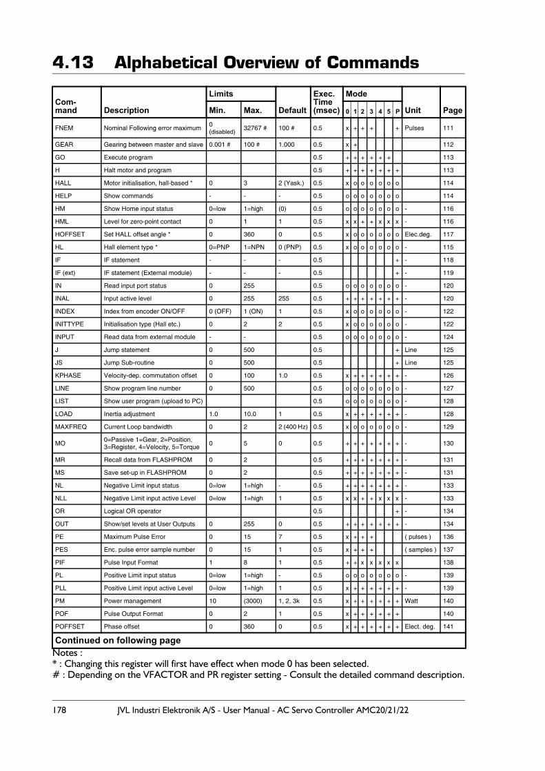
178 JVL Industri Elektronik A/S - User Manual - AC Servo Controller AMC20/21/22
4.13 Alphabetical Overview of Commands
Notes :* : Changing this register will first have effect when mode 0 has been selected. # : Depending on the VFACTOR and PR register setting - Consult the detailed command description.
Com-mand Description
Limits
Default
Exec. Time(msec)
Mode
Unit PageMin. Max. 0 1 2 3 4 5 P
FNEM Nominal Following error maximum 0 (disabled)
32767 # 100 # 0.5 x + + + + Pulses 111
GEAR Gearing between master and slave 0.001 # 100 # 1.000 0.5 x + 112
GO Execute program 0.5 + + + + + + 113
H Halt motor and program 0.5 + + + + + + + 113
HALL Motor initialisation, hall-based * 0 3 2 (Yask.) 0.5 x o o o o o o 114
HELP Show commands - - - 0.5 o o o o o o o 114
HM Show Home input status 0=low 1=high (0) 0.5 o o o o o o o - 116
HML Level for zero-point contact 0 1 1 0.5 x x + + x x x - 116
HOFFSET Set HALL offset angle * 0 360 0 0.5 x o o o o o o Elec.deg. 117
HL Hall element type * 0=PNP 1=NPN 0 (PNP) 0.5 x o o o o o o - 115
IF IF statement - - - 0.5 + - 118
IF (ext) IF statement (External module) - - - 0.5 + - 119
IN Read input port status 0 255 0.5 o o o o o o o - 120
INAL Input active level 0 255 255 0.5 + + + + + + + - 120
INDEX Index from encoder ON/OFF 0 (OFF) 1 (ON) 1 0.5 x o o o o o o - 122
INITTYPE Initialisation type (Hall etc.) 0 2 2 0.5 x o o o o o o - 122
INPUT Read data from external module - - 0.5 o o o o o o o - 124
J Jump statement 0 500 0.5 + Line 125
JS Jump Sub-routine 0 500 0.5 + Line 125
KPHASE Velocity-dep. commutation offset 0 100 1.0 0.5 x + + + + + + - 126
LINE Show program line number 0 500 0.5 o o o o o o o - 127
LIST Show user program (upload to PC) 0.5 o o o o o o o - 128
LOAD Inertia adjustment 1.0 10.0 1 0.5 x + + + + + + - 128
MAXFREQ Current Loop bandwidth 0 2 2 (400 Hz) 0.5 x o o o o o o - 129
MO 0=Passive 1=Gear, 2=Position,3=Register, 4=Velocity, 5=Torque 0 5 0 0.5 + + + + + + + - 130
MR Recall data from FLASHPROM 0 2 0.5 + + + + + + + - 131
MS Save set-up in FLASHPROM 0 2 0.5 + + + + + + + - 131
NL Negative Limit input status 0=low 1=high - 0.5 + + + + + + + - 133
NLL Negative Limit input active Level 0=low 1=high 1 0.5 x x + + x x x - 133
OR Logical OR operator 0.5 + - 134
OUT Show/set levels at User Outputs 0 255 0 0.5 + + + + + + + - 134
PE Maximum Pulse Error 0 15 7 0.5 x + + + ( pulses ) 136
PES Enc. pulse error sample number 0 15 1 0.5 x + + + ( samples ) 137
PIF Pulse Input Format 1 8 1 0.5 + + x x x x x 138
PL Positive Limit input status 0=low 1=high - 0.5 o o o o o o o - 139
PLL Positive Limit input active Level 0=low 1=high 1 0.5 x + + + + + + - 139
PM Power management 10 (3000) 1, 2, 3k 0.5 x + + + + + + Watt 140
POF Pulse Output Format 0 2 1 0.5 x + + + + + + 140
POFFSET Phase offset 0 360 0 0.5 x + + + + + + Elect. deg. 141
Continued on following page
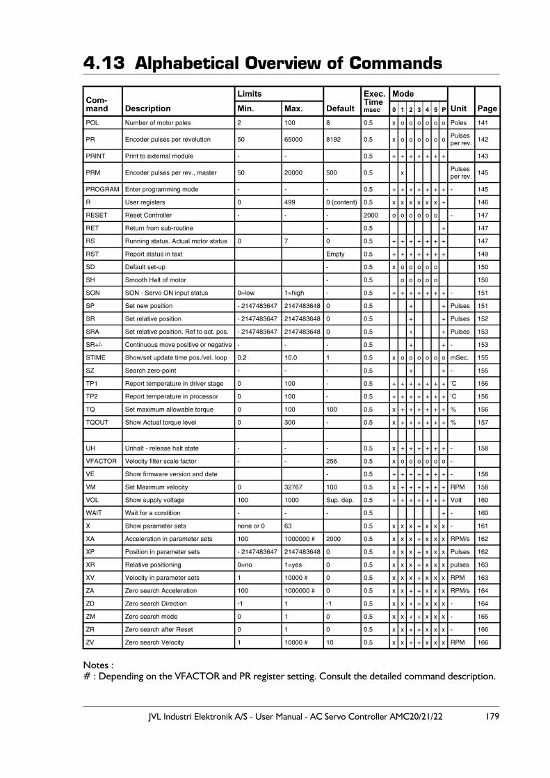
JVL Industri Elektronik A/S - User Manual - AC Servo Controller AMC20/21/22 179
4.13 Alphabetical Overview of Commands
Notes :# : Depending on the VFACTOR and PR register setting. Consult the detailed command description.
Com-mand Description
Limits
Default
Exec.Timemsec
Mode
Unit PageMin. Max. 0 1 2 3 4 5 P
POL Number of motor poles 2 100 8 0.5 x o o o o o o Poles 141
PR Encoder pulses per revolution 50 65000 8192 0.5 x o o o o o o Pulsesper rev. 142
PRINT Print to external module - - 0.5 + + + + + + + 143
PRM Encoder pulses per rev., master 50 20000 500 0.5 x Pulsesper rev. 145
PROGRAM Enter programming mode - - - 0.5 + + + + + + + - 145
R User registers 0 499 0 (content) 0.5 x x x x x x + 146
RESET Reset Controller - - - 2000 o o o o o o - 147
RET Return from sub-routine - 0.5 + 147
RS Running status. Actual motor status 0 7 0 0.5 + + + + + + + 147
RST Report status in text Empty 0.5 + + + + + + + 149
SD Default set-up - 0.5 x o o o o o 150
SH Smooth Halt of motor - 0.5 o o o o o 150
SON SON - Servo ON input status 0=low 1=high - 0.5 + + + + + + + - 151
SP Set new position - 2147483647 2147483648 0 0.5 + + Pulses 151
SR Set relative position - 2147483647 2147483648 0 0.5 + + Pulses 152
SRA Set relative position. Ref to act. pos. - 2147483647 2147483648 0 0.5 + + Pulses 153
SR+/- Continuous move positive or negative - - - 0.5 + + - 153
STIME Show/set update time pos./vel. loop 0.2 10.0 1 0.5 x o o o o o o mSec. 155
SZ Search zero-point - - - 0.5 + + - 155
TP1 Report temperature in driver stage 0 100 - 0.5 + + + + + + + ’C 156
TP2 Report temperature in processor 0 100 - 0.5 + + + + + + + ’C 156
TQ Set maximum allowable torque 0 100 100 0.5 x + + + + + + % 156
TQOUT Show Actual torque level 0 300 - 0.5 x + + + + + + % 157
UH Unhalt - release halt state - - - 0.5 x + + + + + + - 158
VFACTOR Velocity filter scale factor - - 256 0.5 x o o o o o o -
VE Show firmware version and date - 0.5 + + + + + + + - 158
VM Set Maximum velocity 0 32767 100 0.5 x + + + + + + RPM 158
VOL Show supply voltage 100 1000 Sup. dep. 0.5 + + + + + + + Volt 160
WAIT Wait for a condition - - - 0.5 + - 160
X Show parameter sets none or 0 63 0.5 x x x + x x x - 161
XA Acceleration in parameter sets 100 1000000 # 2000 0.5 x x x + x x x RPM/s 162
XP Position in parameter sets - 2147483647 2147483648 0 0.5 x x x + x x x Pulses 162
XR Relative positioning 0=no 1=yes 0 0.5 x x x + x x x pulses 163
XV Velocity in parameter sets 1 10000 # 0 0.5 x x x + x x x RPM 163
ZA Zero search Acceleration 100 1000000 # 0 0.5 x x + + x x x RPM/s 164
ZD Zero search Direction -1 1 -1 0.5 x x + + x x x - 164
ZM Zero search mode 0 1 0 0.5 x x + + x x x - 165
ZR Zero search after Reset 0 1 0 0.5 x x + + x x x - 166
ZV Zero search Velocity 1 10000 # 10 0.5 x x + + x x x RPM 166

180 JVL Industri Elektronik A/S - User Manual - AC Servo Controller AMC20/21/22

JVL Industri Elektronik A/S - User Manual - AC Servo Controller AMC20/21/22 181
5 Appendix
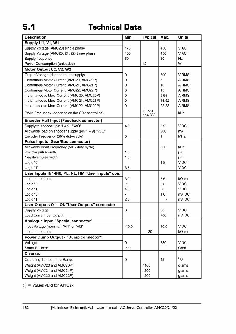
182 JVL Industri Elektronik A/S - User Manual - AC Servo Controller AMC20/21/22
5.1 Technical Data
( ) = Values valid for AMC2x
Description Min. Typical Max. UnitsSupply U1, V1, W1 Supply Voltage (AMC20) single phase 175 450 V ACSupply Voltage (AMC20, 21, 22) three phase 100 450 V ACSupply frequency 50 60 HzPower Consumption (unloaded) 12 W
Motor Output U2, V2, W2Output Voltage (dependent on supply) 0 600 V RMSContinuous Motor Current (AMC20, AMC20P) 0 5 A RMSContinuous Motor Current (AMC21, AMC21P) 0 10 A RMSContinuous Motor Current (AMC22, AMC22P) 0 15 A RMSInstantaneous Max. Current (AMC20, AMC20P) 0 9.55 A RMSInstantaneous Max. Current (AMC21, AMC21P) 0 15.92 A RMSInstantaneous Max. Current (AMC22, AMC22P) 0 22.28 A RMS
PWM Frequency (depends on the CB2 control bit). 19.531or 4.883 kHz
Encoder/Hall-Input (Feedback connector)Supply to encoder (pin 1 + 9) "5VO" 4.8 5.2 V DCAllowable load on encoder supply (pin 1 + 9) "5VO" 200 mAEncoder Frequency (50% duty-cycle) 0 1 MHz
Pulse Inputs (Gear/Bus connector)Allowable Input Frequency (50% duty-cycle) 500 kHzPositive pulse width 1.0 µsNegative pulse width 1.0 µsLogic “0” 1.8 V DCLogic “1” 3.8 V DC
User Inputs IN1-IN8, PL, NL, HM "User Inputs" con.Input Impedance 3.2 3.6 kOhmLogic "0" -1 2.5 V DCLogic "1" 4.5 30 V DCLogic "0" - 1.0 mA DCLogic "1" 2.0 - mA DC
User Outputs O1 - O8 "User Outputs" connectorSupply Voltage 8 28 V DCLoad Current per Output 700 mA DC
Analogue Input "Special connector"Input Voltage (nominal) "AI1" or "AI2" -10.0 10.0 V DCInput Impedance 20 kOhm
Power Dump Output - "Dump connector"Voltage 0 850 V DCShunt Resistor 220 Ohm
Diverse:Operating Temperature Range 0 45 °C
Weight (AMC20 and AMC20P) 4100 gramsWeight (AMC21 and AMC21P) 4200 gramsWeight (AMC22 and AMC22P) 4200 grams
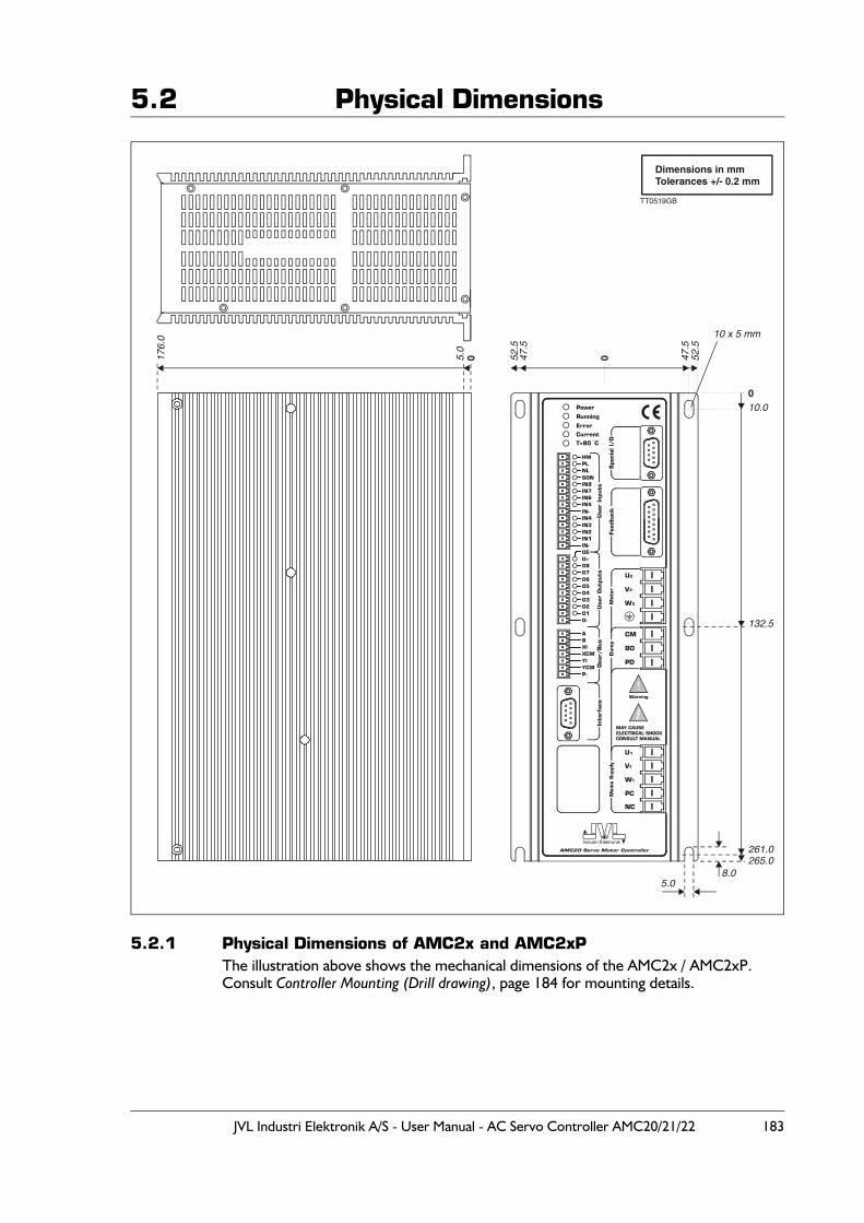
JVL Industri Elektronik A/S - User Manual - AC Servo Controller AMC20/21/22 183
5.2 Physical Dimensions
5.2.1 Physical Dimensions of AMC2x and AMC2xPThe illustration above shows the mechanical dimensions of the AMC2x / AMC2xP.Consult Controller Mounting (Drill drawing), page 184 for mounting details.
0
Dimensions in mmTolerances +/- 0.2 mm
00
10.0
10 x 5 mm
52.5
52.5
176.
0
47.5
47.5
5.0
132.5
265.0
5.08.0
261.0
!
TT0519GB
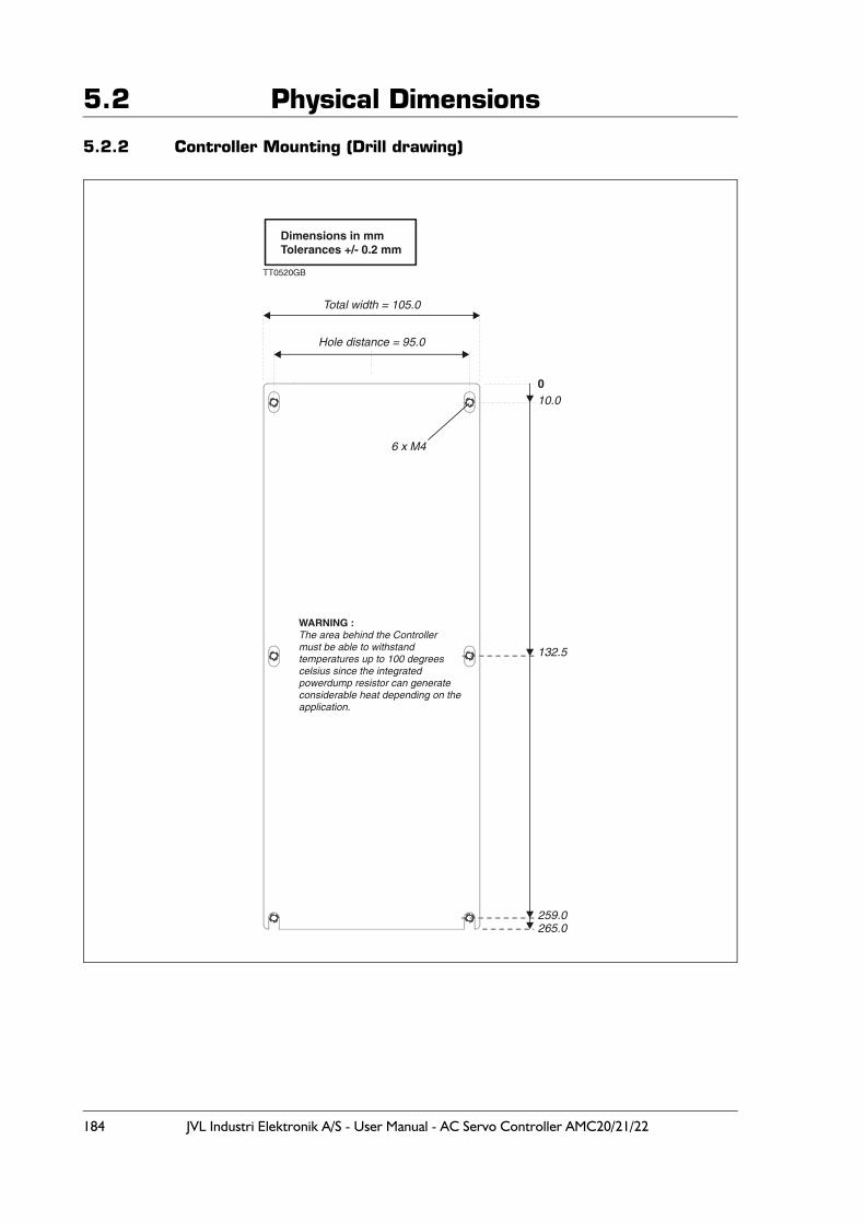
184 JVL Industri Elektronik A/S - User Manual - AC Servo Controller AMC20/21/22
5.2 Physical Dimensions
5.2.2 Controller Mounting (Drill drawing)
0
Dimensions in mmTolerances +/- 0.2 mm
10.0
Total width = 105.0
Hole distance = 95.0
6 x M4
132.5
265.0259.0
TT0520GB
WARNING :The area behind the Controllermust be able to withstand temperatures up to 100 degreescelsius since the integratedpowerdump resistor can generateconsiderable heat depending on the application.
JVL Industri Elektronik A/S - User Manual - AC Servo Controller AMC20/21/22 185
5.3 Power Dissipation
5.3.1 Power Dissipation.The controller is optimized for lowest possible losses since losses means heat dissipation.The total power disipation can be calculated after following formular
Total power dissipation = 40 + (Motor Power * 0.1)
The formular covers worst case which is mains supply 3 x 400 VAC.If only 1 x 230 VAC single phase supply is used the dissipation is much lower.
Example :
In an application the total output power to the motor is 3 kW.This surcomstance result in following power dissipation :
40 + (3000 * 0.1) = 340W
This amount of power (340W) will be dissipated as heat inside the controller.The surounding cabinet must therefore be able to absorb some of this heat.
Please make sure that an area is keept free in each end of the controller to asure that a free air circulation is possible.
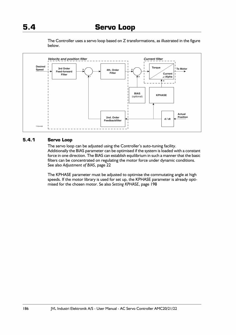
186 JVL Industri Elektronik A/S - User Manual - AC Servo Controller AMC20/21/22
5.4 Servo Loop
The Controller uses a servo loop based on Z transformations, as illustrated in the figure below.
5.4.1 Servo LoopThe servo loop can be adjusted using the Controller’s auto-tuning facility.Additionally the BIAS parameter can be optimised if the system is loaded with a constant force in one direction. The BIAS can establish equilibrium in such a manner that the basic filters can be concentrated on regulating the motor force under dynamic conditions.See also Adjustment of BIAS, page 22
The KPHASE parameter must be adjusted to optimise the commutating angle at high speeds. If the motor library is used for set up, the KPHASE parameter is already opti-mised for the chosen motor. Se also Setting KPHASE, page 198
3rd OrderFeed-forward
Filter
4th. OrderFilter
2nd. OrderFeedbackfilter
BIAS(optional) KPHASE
d / dt
Torque
CurrentAlpha
DesiredSpeed + +
- +
+
ActualPosition
To Motor
TT0544GB
Current filterVelocity and position filter
JVL Industri Elektronik A/S - User Manual - AC Servo Controller AMC20/21/22 187
5.5 Error Indication
In addition to their normal function, the Controller LEDs are also used to indicate vital error conditions. The following describes the normal functions of the LEDs and then their additional functions. See also Error Status Text (EST), page 109, concerning Control-ler error messages.
5.5.1 Error LEDThe Error LED is lit when a fatal error occurs. A fatal error is an error which prevents motor operation, e.g. a fault in an encoder cable, the motor is jammed, a temperature overload, short-circuiting of the motor output, voltage overload, average current ex-ceeded.
5.5.2 Current LEDThe Current LED is lit if the specified average (rated) current (CA) is exceeded for any length of time. The Error LED is also lit.The Current LED is also lit if an overload occurs. The system must be reset after an over-load. See Reset Controller (RESET), page 147.
5.5.3 T>75°C LEDThe T>75°C LED is lit when the Controller’s internal temperature exceeds 75°C. The Controller must be reset.
5.5.4 Out Error LEDThe Out Error LED is lit when an error occurs at one of the eight Outputs O1-O8.
5.5.5 Four LEDs Blinking in SequenceIf the four LEDs Running, Error, Current and T>75°C blink in sequence, it is an indication of a PROM error. When the Controller is switched on, the checksum in the Controller’s program memory (PROM) is verified. If the pre-programmed checksum does not match the calculated checksum, the Controller will not operate the motor. The PROM may be defective. Try resetting the Controller.
5.5.6 Four LEDs Blinking SimultaneouslyIf the four LEDs Running, Error, Current and T>75°C blink simultaneously, a motor error or encoder error has occurred. When the Controller is switched on, a check is carried out to ensure that the motor and encoder are connected correctly. The PWM signal to the motor is gradually increased until movement is registered or the PWM signals reach 50%.
In this way the Controller can check whether:
1. The motor is correctly connected, i.e. moves in the right direction. 2. The motor is blocked, i.e. draws a lot of current without the motor moving.3. The encoder is connected incorrectly.
Check that the motor or encoder is connected correctly. Use the EST command (Error Status Text (EST), page 109) for further information from the Controller.
188 JVL Industri Elektronik A/S - User Manual - AC Servo Controller AMC20/21/22
5.6 Typical Errors
During installation and use of the Controller, various errors may occur. Information about many of these can be obtained from the Controller itself using the EST command (see Error Status Text (EST), page 109). Some error conditions are similar to other errors. The following describes some of the most common errors and possible solutions.
5.6.1 Motion Errors :The motor runs ok but at higher speeds the error message "average current exceeded" appears.
The error could be1. The current filter is not tuned properly. Please re-tune the current filter using
the TUNE1 command. See also Setting the Motor Currents, page 1952. The KPHASE register is not set properly. Please let the motor run at a speed
as high as possible without causing this error. Try then to adjust the KPHASE value until the CL (melt integral) is settling at a minimum. Try now at full speed.
5.6.2 TemperatureThe temperature is very high at the surface of controller or a temperature warning is of-ten displayed in MotoWare.
The error could be1. The ambient temperature is too high. Make sure that the ambient tempera-
tures specified in Technical Data, page 182 is not exceeded.2. The cable length or the cable capacitance is too high.
Decrease the PWM frequency at the motor output by using the CB2 param-eter. See also CB2 - Set low PWM output frequency, page 92.
3. The airflow through the cooling channel in the controller is too bad due to nar-row mounting. Mount an extra fan in the housing around the controller or im-prove the air ciculation by mounting the controller with a better distance to the surounding housing.
Incorrect VelocityIt is important that the servo constants are adjusted correctly. The system cannot main-tain the correct velocity if the servo loop is not adjusted.
Incorrect Velocity even though the servo constants have been adjustedIt is important that the specification of the encoder resolution (pulses/revolution) is set correctly. Use the PR command; see Encoder Pulses (PR), page 142.
The motor does not move to the correct position by selecting XP0XP0 is used for the zero-point search function and has therefore a different function than the other position registers.
The motor and encoder are connected correctly but still report an errorCheck that the encoder type is set correctly using the ET command (page 110).
The motor does not supply the correct torqueIt is important that the servo constants are adjusted. The system cannot produce the cor-rect torque if the servo loop is not adjusted.

JVL Industri Elektronik A/S - User Manual - AC Servo Controller AMC20/21/22 189
5.6 Typical ErrorsFour LEDs blink simultaneouslyA problem has occurred with either the encoder or the motor. The encoder has fallen off or the motor is jammed. In cases where the encoder and motor appear to be con-nected correctly, check the maximum allowable pulse error using the PE command (Maximum Pulse Error (PE), page 136). Check also the encoder type using the ET com-mand; see Encoder Type (ET), page 110.
190 JVL Industri Elektronik A/S - User Manual - AC Servo Controller AMC20/21/22
5.7 Connection of an Unknown Motor Type
This section should be followed if the Controller is to be adjusted for an unknown motor type which is not included in the MotoWare parameter list.Proceed as follows:
1. Find the following data for the actual motor and adjust the Controller accordingly:
— Number of motor poles: parameter POL. See Setting the Number of Motor Poles, page 194.
— Number of encoder pulses per revolution and encoder type: parameters PR, ET, and INDEX. See Set-up of Encoder Resolution, page 191.
— Motor currents. The values of the motor’s allowable average current/peak cur-rent: parameters CA and CP. See Setting the Motor Currents, page 195
It is recommended that the Controller is adjusted without using Hall elements, even if the motor is equipped with Hall elements. These should first be connected and used after the basic adjustment. If the motor does not have Hall elements, follow the instructions in Start-up of Motor without Hall Element, page 199.If the motor has Hall elements, these may be used. See Setting the Hall Element, page 196.
2. Adjust the other critical parameters for the actual type of motor, including:— Current filter. See Current filter optimizing, page 16— Servo filter parameters. See Adjustment of Servo Regulation, page 18.— Velocity dependent commutation offset: parameter KPHASE. See Setting
KPHASE, page 198.
A usefull command for determine the motor parameters is the Motor test (MTEST), page 132.
For set up of other Controller functions, see Software, page 49
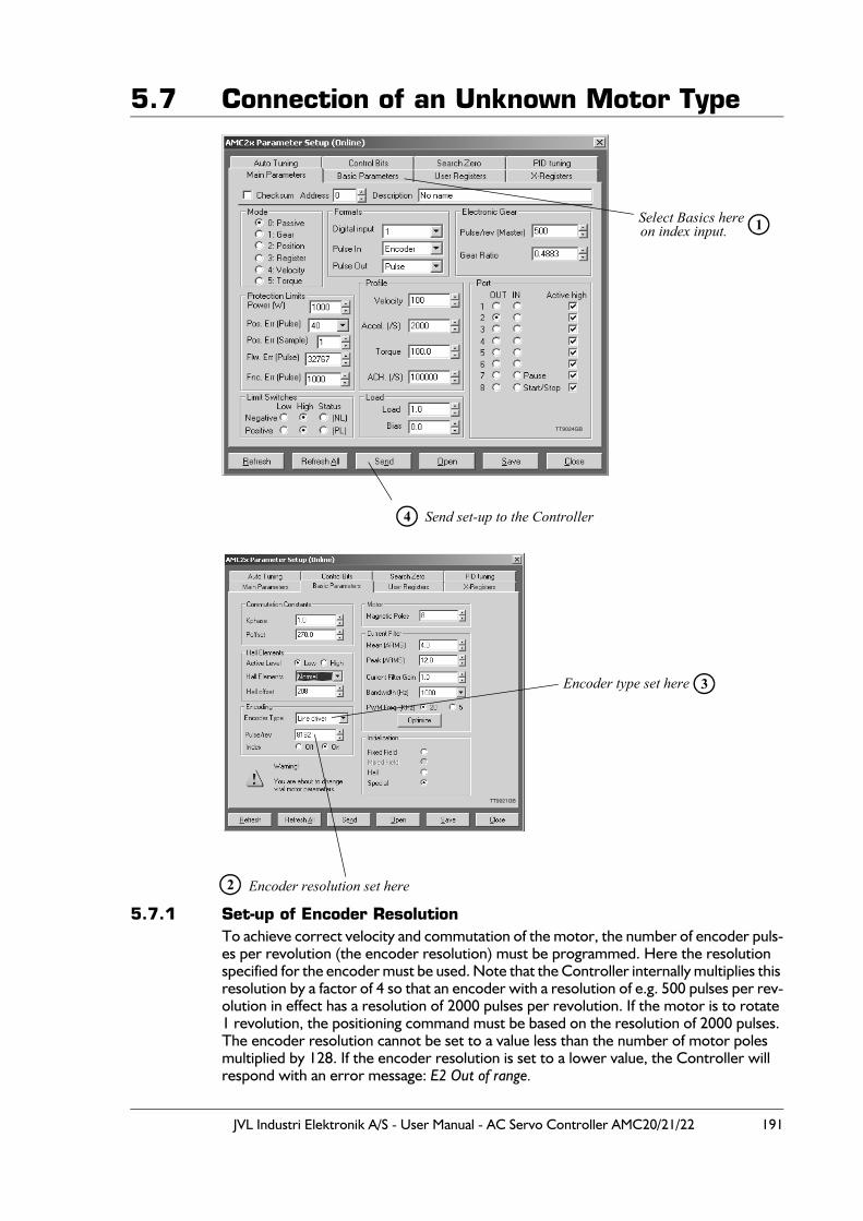
JVL Industri Elektronik A/S - User Manual - AC Servo Controller AMC20/21/22 191
5.7 Connection of an Unknown Motor Type
5.7.1 Set-up of Encoder Resolution To achieve correct velocity and commutation of the motor, the number of encoder puls-es per revolution (the encoder resolution) must be programmed. Here the resolution specified for the encoder must be used. Note that the Controller internally multiplies this resolution by a factor of 4 so that an encoder with a resolution of e.g. 500 pulses per rev-olution in effect has a resolution of 2000 pulses per revolution. If the motor is to rotate 1 revolution, the positioning command must be based on the resolution of 2000 pulses. The encoder resolution cannot be set to a value less than the number of motor poles multiplied by 128. If the encoder resolution is set to a lower value, the Controller will respond with an error message: E2 Out of range.
Send set-up to the Controller
Select Basics hereon index input.
4
1
TT9024GB
Encoder resolution set here
Encoder type set here
2
3
TT9021GB
192 JVL Industri Elektronik A/S - User Manual - AC Servo Controller AMC20/21/22
5.7 Connection of an Unknown Motor TypeThe encoder resolution must be set to a value in the range 256 to 20000 pulses per rev-olution.Set the encoder resolution in the Pulse/rev (S) field and send the information by pressing Send. If required, store the value in the Controller’s non-volatile memory by pressing FLASHPROM.
If the encoder resolution is set via the on-line editor, the PR command is used.
Example:PR=2048(enter) Sets the encoder resolution to 2048 pulses per revolution.PR(enter) Displays the current encoder resolution set-up.
To store the value in the Controller’s permanent memory, key MS (enter).
5.7.2 Setting the Encoder TypeThe encoder used with the AMC Controller can be of either a PNP or NPN type. In ad-dition, the Controller accepts both a balanced and unbalanced signal from a standard 2-channel incremental encoder. For connection of the encoder, see Encoder Input, page 29.The Encoder Type field determines which type of encoder is connected to the Controller. If an encoder with a balanced output is used, this setting can be omitted. If however an unbalanced NPN type encoder is used, the field must be set to NPN. If the encoder is a PNP type, the field is set to PNP.Send the information to the Controller by pressing Send. If required, save the setting in the Controller’s non-volatile memory by pressing FLASHPROM.
If the encoder type is set via the on-line editor, the ET command is used.
Example:ET=0(enter) Set encoder type to PNP.ET=1(enter) Set encoder type to NPN.ET(enter) Display current setting for encoder type
To store the setting in the Controller’s permanent memory, key MS (enter).

JVL Industri Elektronik A/S - User Manual - AC Servo Controller AMC20/21/22 193
5.7 Connection of an Unknown Motor Type
5.7.3 Setting the Index InputIt is recommended that an encoder with an index channel is used. If an encoder with in-dex channel is used, the Controller’s Index Input (EZ1 and EZ2) must be enabled by Setting the INDEX paramter to 1 (INDEX=1).The index inputs will only read a transistion at the input therefore the polarity of the in-dex pulse is irrelevant.
Illustration of active levels:
If the index input is enabled via the on-line editor, the INDEX command can be used.
Example:INDEX=1(enter) Enable the index input.INDEX(enter) Display current index input status (enabled or disabled).
EncoderA channel
EncoderA channel
EncoderB channel
EncoderB channel
EncoderIndex channel
EncoderIndex channel
90 degrees 90 degrees
Encoder with active high index Encoder with active low index
TT0009GB
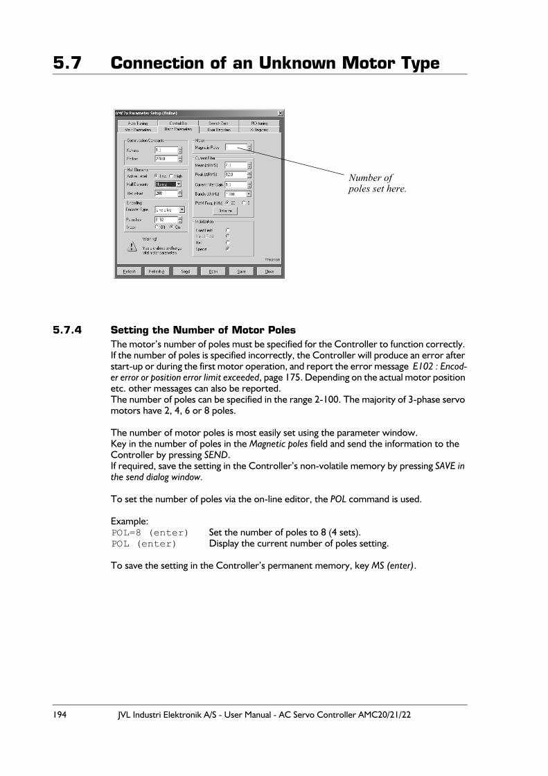
194 JVL Industri Elektronik A/S - User Manual - AC Servo Controller AMC20/21/22
5.7 Connection of an Unknown Motor Type
5.7.4 Setting the Number of Motor PolesThe motor’s number of poles must be specified for the Controller to function correctly. If the number of poles is specified incorrectly, the Controller will produce an error after start-up or during the first motor operation, and report the error message E102 : Encod-er error or position error limit exceeded, page 175. Depending on the actual motor position etc. other messages can also be reported.The number of poles can be specified in the range 2-100. The majority of 3-phase servo motors have 2, 4, 6 or 8 poles.
The number of motor poles is most easily set using the parameter window.Key in the number of poles in the Magnetic poles field and send the information to the Controller by pressing SEND.If required, save the setting in the Controller’s non-volatile memory by pressing SAVE in the send dialog window.
To set the number of poles via the on-line editor, the POL command is used.
Example:POL=8 (enter) Set the number of poles to 8 (4 sets).POL (enter) Display the current number of poles setting.
To save the setting in the Controller’s permanent memory, key MS (enter).
Number of poles set here.
TT9021GB
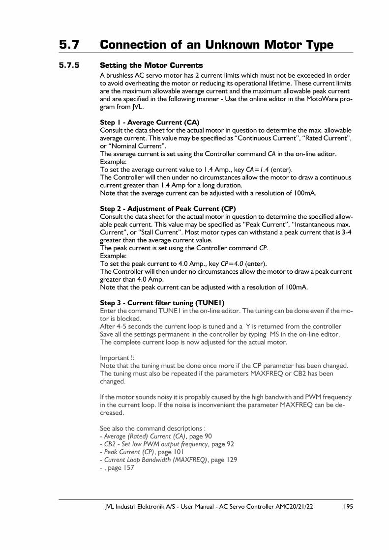
JVL Industri Elektronik A/S - User Manual - AC Servo Controller AMC20/21/22 195
5.7 Connection of an Unknown Motor Type
5.7.5 Setting the Motor CurrentsA brushless AC servo motor has 2 current limits which must not be exceeded in order to avoid overheating the motor or reducing its operational lifetime. These current limits are the maximum allowable average current and the maximum allowable peak current and are specified in the following manner - Use the online editor in the MotoWare pro-gram from JVL.
Step 1 - Average Current (CA)Consult the data sheet for the actual motor in question to determine the max. allowable average current. This value may be specified as “Continuous Current”, “Rated Current”, or “Nominal Current”.The average current is set using the Controller command CA in the on-line editor.Example:To set the average current value to 1.4 Amp., key CA=1.4 (enter).The Controller will then under no circumstances allow the motor to draw a continuous current greater than 1.4 Amp for a long duration. Note that the average current can be adjusted with a resolution of 100mA.
Step 2 - Adjustment of Peak Current (CP)Consult the data sheet for the actual motor in question to determine the specified allow-able peak current. This value may be specified as “Peak Current”, “Instantaneous max. Current”, or “Stall Current”. Most motor types can withstand a peak current that is 3-4 greater than the average current value. The peak current is set using the Controller command CP.Example:To set the peak current to 4.0 Amp., key CP=4.0 (enter).The Controller will then under no circumstances allow the motor to draw a peak current greater than 4.0 Amp. Note that the peak current can be adjusted with a resolution of 100mA.
Step 3 - Current filter tuning (TUNE1)Enter the command TUNE1 in the on-line editor. The tuning can be done even if the mo-tor is blocked.After 4-5 seconds the current loop is tuned and a Y is returned from the controllerSave all the settings permanent in the controller by typing MS in the on-line editor.The complete current loop is now adjusted for the actual motor.
Important !:Note that the tuning must be done once more if the CP parameter has been changed.The tuning must also be repeated if the parameters MAXFREQ or CB2 has been changed.
If the motor sounds noisy it is propably caused by the high bandwith and PWM frequency in the current loop. If the noise is inconvenient the parameter MAXFREQ can be de-creased.
See also the command descriptions :- Average (Rated) Current (CA), page 90- CB2 - Set low PWM output frequency, page 92- Peak Current (CP), page 101- Current Loop Bandwidth (MAXFREQ), page 129- , page 157
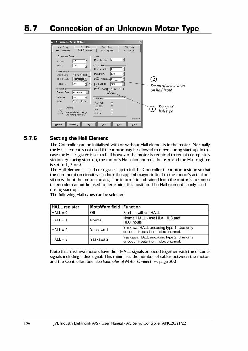
196 JVL Industri Elektronik A/S - User Manual - AC Servo Controller AMC20/21/22
5.7 Connection of an Unknown Motor Type
5.7.6 Setting the Hall Element The Controller can be initialised with or without Hall elements in the motor. Normally the Hall element is not used if the motor may be allowed to move during start-up. In this case the Hall register is set to 0. If however the motor is required to remain completely stationary during start-up, the motor’s Hall element must be used and the Hall register is set to 1, 2 or 3.The Hall element is used during start-up to tell the Controller the motor position so that the commutation circuitry can lock the applied magnetic field to the motor’s actual po-sition without the motor moving. The information obtained from the motor’s incremen-tal encoder cannot be used to determine this position. The Hall element is only used during start-up. The following Hall types can be selected.
Note that Yaskawa motors have their HALL signals encoded together with the encoder signals including index-signal. This minimises the number of cables between the motor and the Controller. See also Examples of Motor Connection, page 200
HALL register MotoWare field FunctionHALL = 0 Off Start-up without HALL
HALL = 1 Normal Normal HALL - use HLA, HLB andHLC inputs
HALL = 2 Yaskawa 1 Yaskawa HALL encoding type 1. Use onlyencoder inputs incl. Index channel.
HALL = 3 Yaskawa 2 Yaskawa HALL encoding type 2. Use onlyencoder inputs incl. Index channel.
Set up of active levelon hall input
1
2
Set up ofhall type
TT9021GB
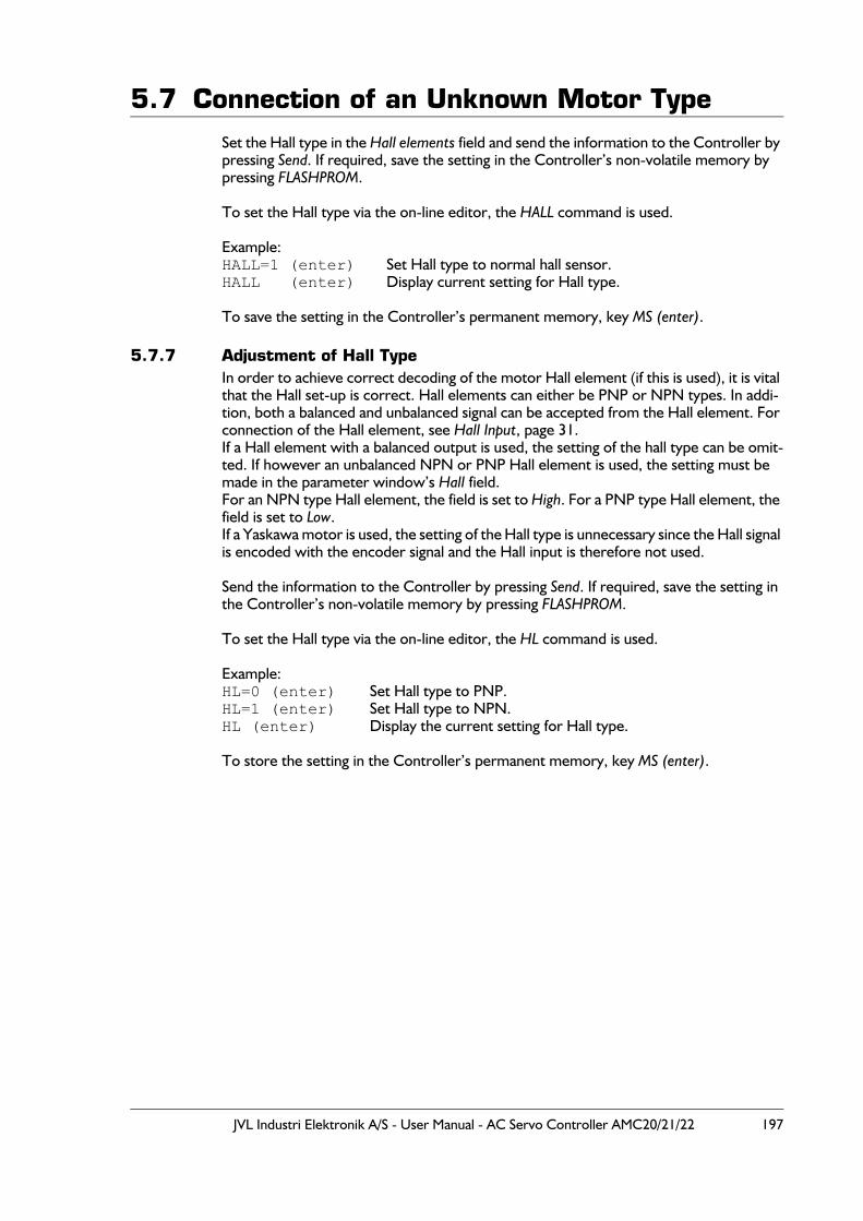
JVL Industri Elektronik A/S - User Manual - AC Servo Controller AMC20/21/22 197
5.7 Connection of an Unknown Motor TypeSet the Hall type in the Hall elements field and send the information to the Controller by pressing Send. If required, save the setting in the Controller’s non-volatile memory by pressing FLASHPROM.
To set the Hall type via the on-line editor, the HALL command is used.
Example:HALL=1 (enter) Set Hall type to normal hall sensor.HALL (enter) Display current setting for Hall type.
To save the setting in the Controller’s permanent memory, key MS (enter).
5.7.7 Adjustment of Hall TypeIn order to achieve correct decoding of the motor Hall element (if this is used), it is vital that the Hall set-up is correct. Hall elements can either be PNP or NPN types. In addi-tion, both a balanced and unbalanced signal can be accepted from the Hall element. For connection of the Hall element, see Hall Input, page 31.If a Hall element with a balanced output is used, the setting of the hall type can be omit-ted. If however an unbalanced NPN or PNP Hall element is used, the setting must be made in the parameter window’s Hall field.For an NPN type Hall element, the field is set to High. For a PNP type Hall element, the field is set to Low.If a Yaskawa motor is used, the setting of the Hall type is unnecessary since the Hall signal is encoded with the encoder signal and the Hall input is therefore not used.
Send the information to the Controller by pressing Send. If required, save the setting in the Controller’s non-volatile memory by pressing FLASHPROM.
To set the Hall type via the on-line editor, the HL command is used.
Example:HL=0 (enter) Set Hall type to PNP.HL=1 (enter) Set Hall type to NPN.HL (enter) Display the current setting for Hall type.
To store the setting in the Controller’s permanent memory, key MS (enter).
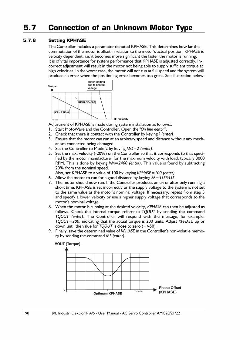
198 JVL Industri Elektronik A/S - User Manual - AC Servo Controller AMC20/21/22
5.7 Connection of an Unknown Motor Type
5.7.8 Setting KPHASEThe Controller includes a parameter denoted KPHASE. This determines how far the commutation of the motor is offset in relation to the motor’s actual position. KPHASE is velocity dependent, i.e. it becomes more significant the faster the motor is running.It is of vital importance for system performance that KPHASE is adjusted correctly. In-correct adjustment will result in the motor not being able to supply sufficient torque at high velocities. In the worst case, the motor will not run at full speed and the system will produce an error when the positioning error becomes too great. See illustration below.
Adjustment of KPHASE is made during system installation as follows:.1. Start MotoWare and the Controller. Open the "On line editor”.2. Check that there is contact with the Controller by keying ? (enter).3. Ensure that the motor can run at an arbitrary speed and distance without any mech-
anism connected being damaged.4. Set the Controller to Mode 2 by keying MO=2 (enter).5. Set the max. velocity (-20%) on the Controller so that it corresponds to that speci-
fied by the motor manufacturer for the maximum velocity with load, typically 3000RPM. This is done by keying VM=2400 (enter). This value is found by subtracting20% from the nominal speed.Also, set KPHASE to a value of 100 by keying KPHASE=100 (enter)
6. Allow the motor to run for a good distance by keying SP=5555555.7. The motor should now run. If the Controller produces an error after only running a
short time, KPHASE is set incorrectly or the supply voltage to the system is not setto the same value as the motor’s nominal voltage. If necessary, repeat from step 5and specify a lower velocity or use a higher supply voltage that corresponds to themotor’s nominal voltage.
8. When the motor is running at the desired velocity, KPHASE can then be adjusted asfollows. Check the internal torque reference TQOUT by sending the commandTQOUT (enter). The Controller will respond with the message, for example,TQOUT=200, indicating that the actual torque is 200 units. Adjust KPHASE up ordown until the value for TQOUT is close to zero (+/-50).
9. Finally, save the determined value of KPHASE in the Controller’s non-volatile memo-ry by sending the command MS (enter).
Torque
Velocity
Motor limitingdue to limitedvoltage
KPHASE=0
KPHASE=500
TT0046-GB
VOUT (Torque)
Phase Offset(KPHASE)Optimum KPHASE
00 TT0548GB
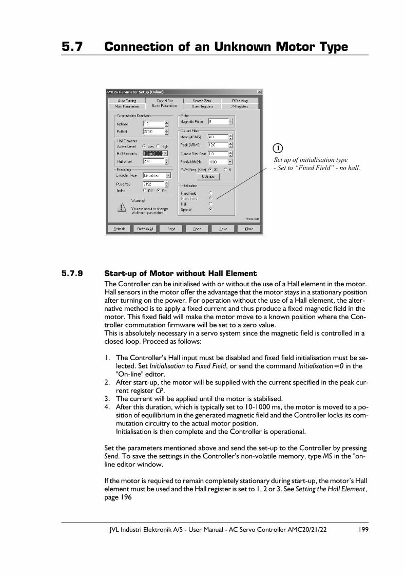
JVL Industri Elektronik A/S - User Manual - AC Servo Controller AMC20/21/22 199
5.7 Connection of an Unknown Motor Type
5.7.9 Start-up of Motor without Hall Element The Controller can be initialised with or without the use of a Hall element in the motor. Hall sensors in the motor offer the advantage that the motor stays in a stationary position after turning on the power. For operation without the use of a Hall element, the alter-native method is to apply a fixed current and thus produce a fixed magnetic field in the motor. This fixed field will make the motor move to a known position where the Con-troller commutation firmware will be set to a zero value.This is absolutely necessary in a servo system since the magnetic field is controlled in a closed loop. Proceed as follows:
1. The Controller’s Hall input must be disabled and fixed field initialisation must be se-lected. Set Initialisation to Fixed Field, or send the command Initialisation=0 in the "On-line" editor.
2. After start-up, the motor will be supplied with the current specified in the peak cur-rent register CP.
3. The current will be applied until the motor is stabilised. 4. After this duration, which is typically set to 10-1000 ms, the motor is moved to a po-
sition of equilibrium in the generated magnetic field and the Controller locks its com-mutation circuitry to the actual motor position.Initialisation is then complete and the Controller is operational.
Set the parameters mentioned above and send the set-up to the Controller by pressing Send. To save the settings in the Controller’s non-volatile memory, type MS in the "on-line editor window.
If the motor is required to remain completely stationary during start-up, the motor’s Hall element must be used and the Hall register is set to 1, 2 or 3. See Setting the Hall Element, page 196
Set up of initialisation type
1
- Set to “Fixed Field” - no hall.
TT9021GB
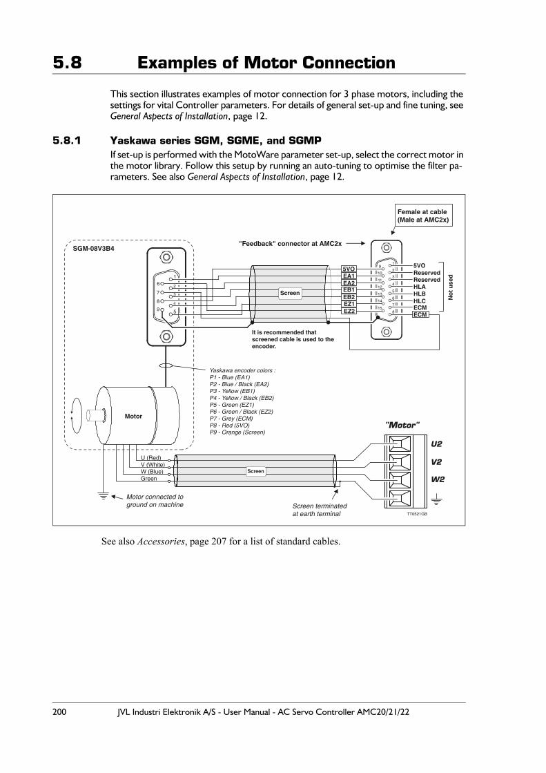
200 JVL Industri Elektronik A/S - User Manual - AC Servo Controller AMC20/21/22
5.8 Examples of Motor Connection
This section illustrates examples of motor connection for 3 phase motors, including the settings for vital Controller parameters. For details of general set-up and fine tuning, see General Aspects of Installation, page 12.
5.8.1 Yaskawa series SGM, SGME, and SGMPIf set-up is performed with the MotoWare parameter set-up, select the correct motor in the motor library. Follow this setup by running an auto-tuning to optimise the filter pa-rameters. See also General Aspects of Installation, page 12.
See also Accessories, page 207 for a list of standard cables.
U (Red)
Green
V (White)
SGM-08V3B4
W (Blue)
Motor connected toground on machine Screen terminated
at earth terminal TT0521GB
5VO
No
t u
sed
ECMECM
HLA
ReservedReserved
HLBHLC
5VOEA1EA2EB1EB2EZ1EZ2
1
2
3
4
5
6
7
8
9
10
11
12
13
14
15
It is recommended that screened cable is used to theencoder.
Motor
Screen
1
2
3
4
5
6
7
8
9
Yaskawa encoder colors :P1 - Blue (EA1)P2 - Blue / Black (EA2)P3 - Yellow (EB1)P4 - Yellow / Black (EB2)P5 - Green (EZ1)P6 - Green / Black (EZ2)P7 - Grey (ECM)P8 - Red (5VO)P9 - Orange (Screen)
Screen
"Feedback" connector at AMC2x
U2
V2
W2
"Motor"
Female at cable(Male at AMC2x)
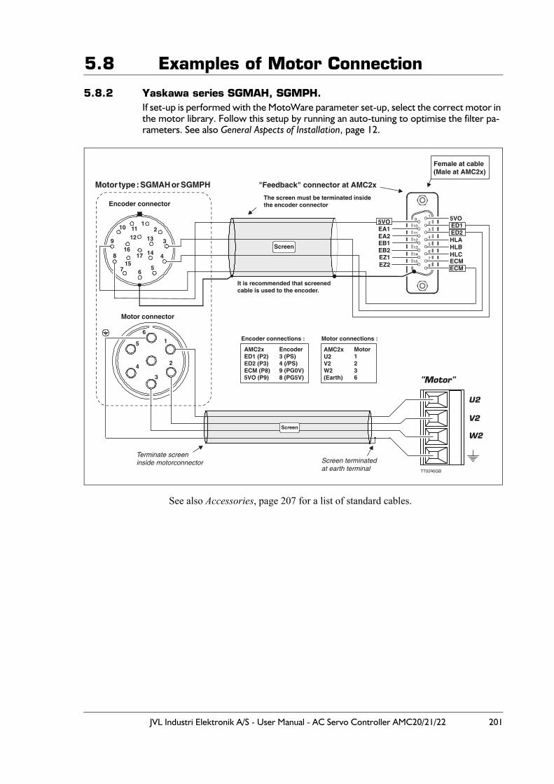
JVL Industri Elektronik A/S - User Manual - AC Servo Controller AMC20/21/22 201
5.8 Examples of Motor Connection
5.8.2 Yaskawa series SGMAH, SGMPH.If set-up is performed with the MotoWare parameter set-up, select the correct motor in the motor library. Follow this setup by running an auto-tuning to optimise the filter pa-rameters. See also General Aspects of Installation, page 12.
See also Accessories, page 207 for a list of standard cables.
Encoder connector
Motor connector
Terminate screeninside motorconnector Screen terminated
at earth terminal TT0590GB
5VO
ECM
ED2ED1
ECM
HLAHLBHLC
5VOEA1EA2EB1EB2EZ1EZ2
1
2
3
4
5
6
7
8
9
10
11
12
13
14
15
It is recommended that screenedcable is used to the encoder.
The screen must be terminated insidethe encoder connector
Motor type : SGMAH or SGMPH "Feedback" connector at AMC2x
Female at cable(Male at AMC2x)
Encoder
8 (PG5V)
3 (PS)4 (/PS)9 (PG0V)
Encoder connections : Motor connections :
Motor1236
AMC2xU2V2W2(Earth)
AMC2xED1 (P2)ED2 (P3)ECM (P8)5VO (P9)
U2
V2
W2
"Motor"
12
3
4
567
8
9
10 1112 13
14
15
1617
1
4
3
6
2
5
Screen
Screen
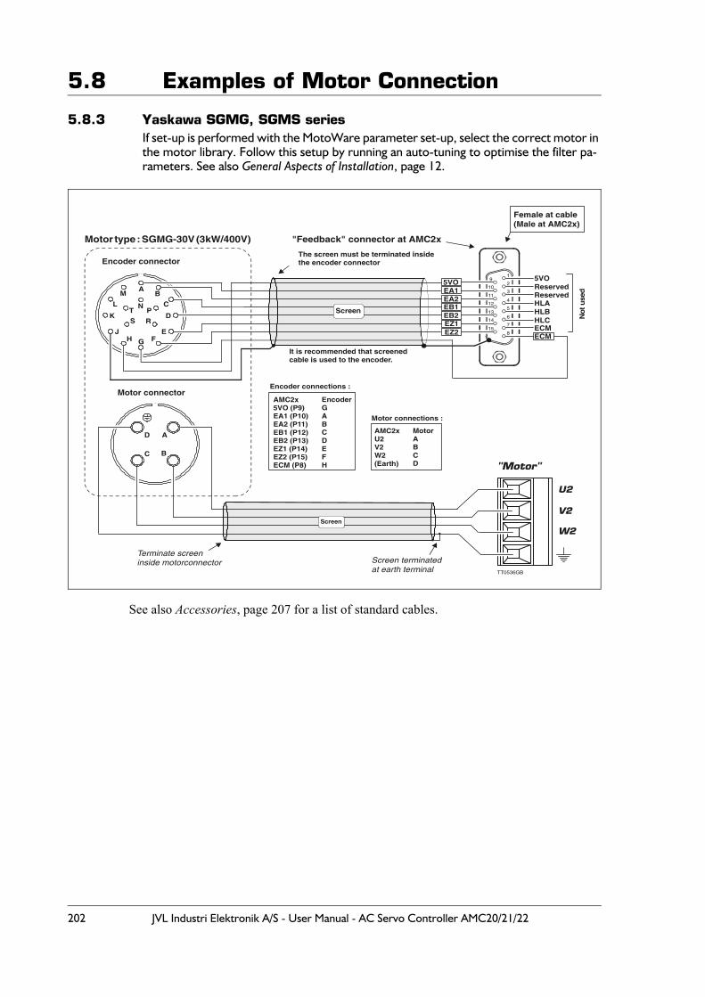
202 JVL Industri Elektronik A/S - User Manual - AC Servo Controller AMC20/21/22
5.8 Examples of Motor Connection
5.8.3 Yaskawa SGMG, SGMS seriesIf set-up is performed with the MotoWare parameter set-up, select the correct motor in the motor library. Follow this setup by running an auto-tuning to optimise the filter pa-rameters. See also General Aspects of Installation, page 12.
See also Accessories, page 207 for a list of standard cables.
Encoder connector
Motor connector
Terminate screeninside motorconnector Screen terminated
at earth terminal TT0536GB
5VO
No
t u
sed
ECMECM
HLA
ReservedReserved
HLBHLC
5VOEA1EA2EB1EB2EZ1EZ2
1
2
3
4
5
6
7
8
9
10
11
12
13
14
15
It is recommended that screenedcable is used to the encoder.
The screen must be terminated insidethe encoder connector
Motor type : SGMG-30V (3kW/400V)
Screen
"Feedback" connector at AMC2x
Female at cable(Male at AMC2x)
EncoderGABCDEFH
Encoder connections :
Motor connections :
MotorABCD
AMC2xU2V2W2(Earth)
AMC2x5VO (P9)EA1 (P10)EA2 (P11)EB1 (P12)EB2 (P13)EZ1 (P14)EZ2 (P15)ECM (P8)
U2
V2
W2
"Motor"
AB
C
DS
K
HE
FG
R
PN
T
M
L
J
A
BC
D
Screen
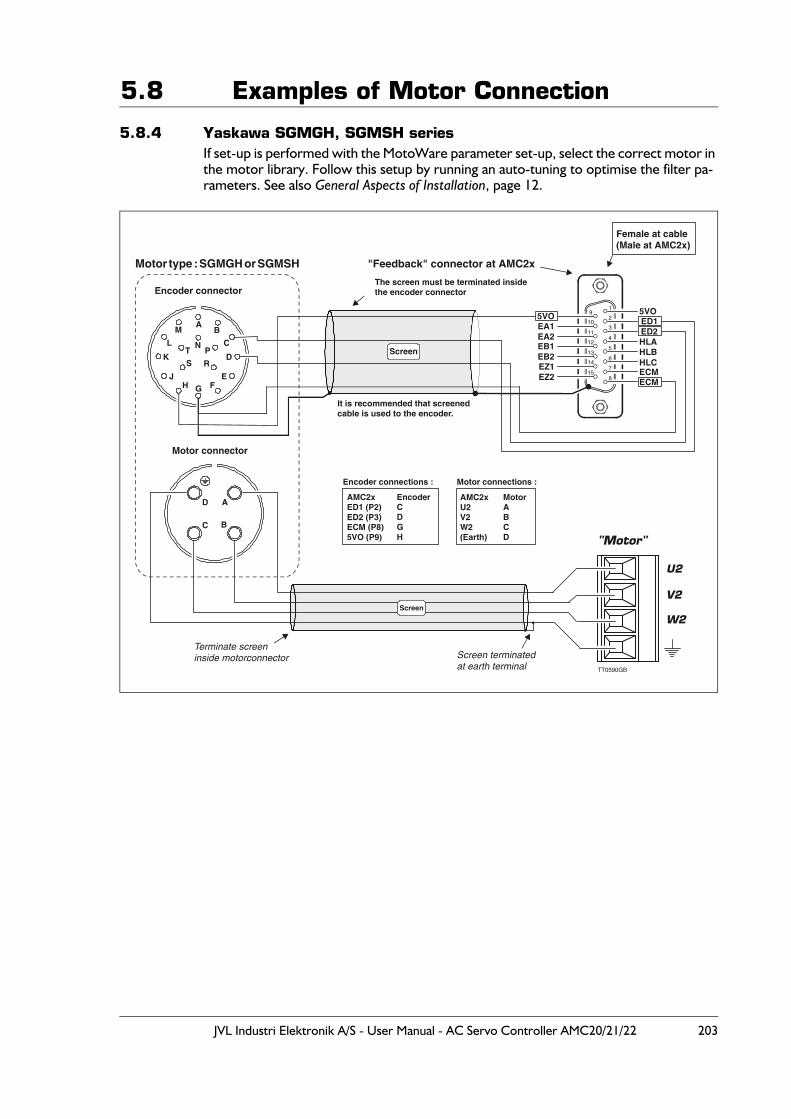
JVL Industri Elektronik A/S - User Manual - AC Servo Controller AMC20/21/22 203
5.8 Examples of Motor Connection
5.8.4 Yaskawa SGMGH, SGMSH seriesIf set-up is performed with the MotoWare parameter set-up, select the correct motor in the motor library. Follow this setup by running an auto-tuning to optimise the filter pa-rameters. See also General Aspects of Installation, page 12.
Encoder connector
Motor connector
Terminate screeninside motorconnector Screen terminated
at earth terminal TT0590GB
5VO
ECM
ED2ED1
ECM
HLAHLBHLC
5VOEA1EA2EB1EB2EZ1EZ2
1
2
3
4
5
6
7
8
9
10
11
12
13
14
15
It is recommended that screenedcable is used to the encoder.
The screen must be terminated insidethe encoder connector
Motor type : SGMGH or SGMSH "Feedback" connector at AMC2x
Female at cable(Male at AMC2x)
EncoderCDGH
Encoder connections : Motor connections :
MotorABCD
AMC2xU2V2W2(Earth)
AMC2xED1 (P2)ED2 (P3)ECM (P8)5VO (P9)
U2
V2
W2
"Motor"
AB
C
DS
K
HE
FG
R
PN
T
M
L
J
A
BC
D
Screen
Screen
204 JVL Industri Elektronik A/S - User Manual - AC Servo Controller AMC20/21/22
5.8 Examples of Motor Connection
5.8.5 Linear Drives - Size 2504 with HallIf set-up is performed with the MotoWare parameter set-up, select the correct motor in the motor library. Follow this setup by running an auto-tuning to optimise the filter pa-rameters. See also General Aspects of Installation, page 12.
Motor connections.Motor AMC2x motor connector.Red U2Yellow V2Blue W2Green Earth
Hall connections.Hall AMC2x feedback connector (SUBD15 pole)H0+ (Yellow) Pin 4H1+ (Violet) Pin 5H2+ (Blue) Pin 60V (Green) Pin 7+V (Red) Pin 1Black UnusedWhite UnusedGrey UnusedBrown UnusedPink UnusedShield Case.
Encoder AMC2x feedback connector (SUBD15 pole)(Renishaw 9pole)A+ (Pin 2) Pin 10A- (Pin 6) Pin 11B+ (Pin 4) Pin 12B- (Pin 8) Pin 13Z+ (Pin 3) Pin 14Z- (Pin 7) Pin 155V (Pin 5) Pin 90V (Pin 1) Pin 8Inner shield (Pin 9) Pin 8Outer shield Case
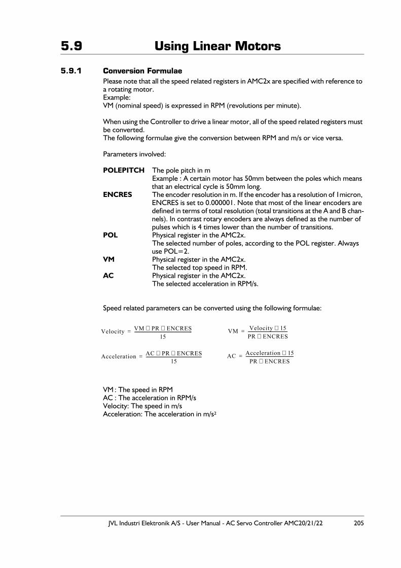
JVL Industri Elektronik A/S - User Manual - AC Servo Controller AMC20/21/22 205
5.9 Using Linear Motors
5.9.1 Conversion FormulaePlease note that all the speed related registers in AMC2x are specified with reference to a rotating motor.Example:VM (nominal speed) is expressed in RPM (revolutions per minute).
When using the Controller to drive a linear motor, all of the speed related registers must be converted.The following formulae give the conversion between RPM and m/s or vice versa.
Parameters involved:
POLEPITCH The pole pitch in mExample : A certain motor has 50mm between the poles which means that an electrical cycle is 50mm long.
ENCRES The encoder resolution in m. If the encoder has a resolution of 1micron, ENCRES is set to 0.000001. Note that most of the linear encoders are defined in terms of total resolution (total transitions at the A and B chan-nels). In contrast rotary encoders are always defined as the number of pulses which is 4 times lower than the number of transitions.
POL Physical register in the AMC2x.The selected number of poles, according to the POL register. Always use POL=2.
VM Physical register in the AMC2x.The selected top speed in RPM.
AC Physical register in the AMC2x.The selected acceleration in RPM/s.
Speed related parameters can be converted using the following formulae:
VM : The speed in RPMAC : The acceleration in RPM/sVelocity: The speed in m/sAcceleration: The acceleration in m/s²
Velocity VM PR ENCRES⋅ ⋅15
---------------------------------------------------------= VM Velocity 15⋅PR ENCRES⋅---------------------------------------=
Acceleration AC PR ENCRES⋅ ⋅15
-------------------------------------------------------= AC Acceleration 15⋅PR ENCRES⋅
-----------------------------------------------=
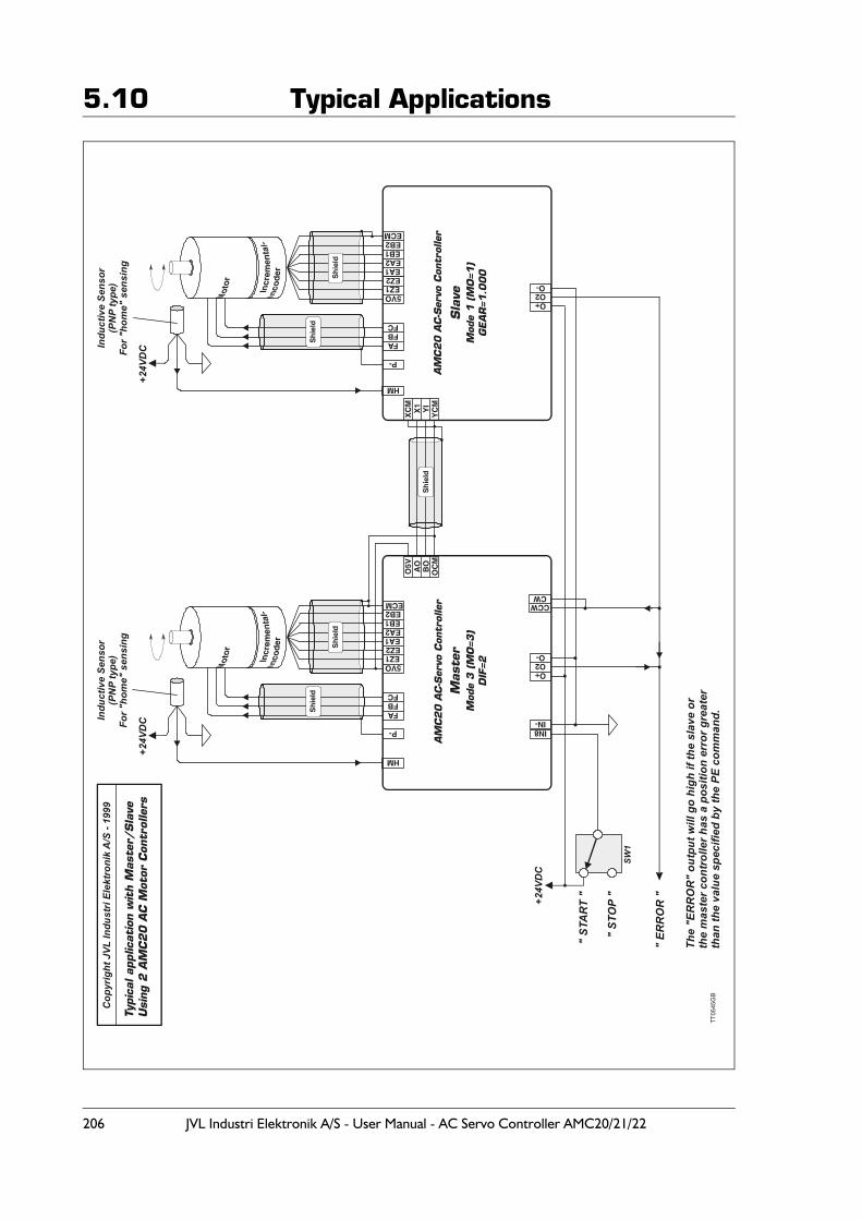
206 JVL Industri Elektronik A/S - User Manual - AC Servo Controller AMC20/21/22
5.10 Typical Applications
EZ15VO
EZ2EA1
EB1
EB1
EA2
EA2
EB2
EB2
ECM
ECM
EZ15VO
EZ2EA1
AO
O5V BO
OC
M
IN-
O2
CCW
O2
IN8
O+
O+
O-
CW
O-
X1
XC
M
YI
YC
M
P-
HM
HM
P-
FB
FB
FA
FA
FC
FC
Sh
ield
Sh
ield
Sh
ield
Sh
ield
AM
C20
AC
-Ser
vo C
ontr
olle
r
Mod
e 3 (
MO
=3)
DIF
=2M
ode
1 (
MO
=1)
GEA
R=1
.000
AM
C2
0 A
C-S
ervo
Con
trol
ler
Mas
ter
Sla
ve
Sh
ield
+24V
DC
" ST
AR
T "
" ST
OP
"SW
1
Indu
ctiv
e Se
nsor
(PN
P ty
pe)
For "
hom
e" s
ensi
ng
Indu
ctiv
e Se
nsor
(PN
P ty
pe)
For "
hom
e" s
ensi
ng
+24V
DC
+24V
DC
" ER
RO
R "
Typic
al a
pplic
atio
n w
ith M
aste
r/Sla
veU
sing
2 A
MC
20 A
C M
otor
Con
trol
lers
The
"ER
RO
R"
outp
ut w
ill g
o hi
gh if
the
slav
e or
the
mas
ter c
ontr
olle
r has
a p
ositi
on e
rror
gre
ater
than
the
valu
e sp
ecifi
ed b
y th
e PE
com
man
d.
Cop
yrig
ht J
VL In
dust
ri El
ektr
onik
A/S
- 19
99
TT
0545
GB
JVL Industri Elektronik A/S - User Manual - AC Servo Controller AMC20/21/22 207
5.11 Accessories
JVL supplies the following accessories for use with the Controller.
5.11.1 SoftwareJVL’s unique MotoWare software can be used for set up and installation of the Control-ler. MotoWare also includes a motor library and program editor for making advanced motion-control programs which can be downloaded to the AMC2xP Controllers.
5.11.2 CablesThe following cables are available for programming interface, motor etc.
All motor cables can be delivered in any length. Specify the WM number and 2 digits de-pending on the motor type. The last 2 digits specify the required length in metres. Example : WM1905 specifies a cable for a Yaskawa SGM/SGMP motor and a required
length of 5 metres.
All encoder cables can be delivered in any length. Specify the WE number and 2 digits depending on the motor type. The last 2 digits specify the required length in metres. Example : WE1403 specifies a cable for a Yaskawa SGM/SGMP motor and a required
length of 3 metres.
Motor cables (only motor)Type (order no.) Motor manufacturer Motor type Power Range
WM19xx Yaskawa SGM(E) / SGMP SGM(E) : 0-750WSGMP : 0-1500W
WM20xx Drive Systems BLS70 750W
WM21xx Yaskawa SGMG/SGMS SGMG : 0.5 - 0.9 - 1.3 kWSGMS : 1.0 - 1.5 kW
WM22xx Yaskawa SGMG/SGMS SGMG : 2 - 3 kWSGMS : 3 kW
WM23xx Yaskawa SGMG/SGMS SGMG : 4.4 - 5.5 - 7.5 kWSGMS : 4.0 - 5.0 kW
Encoder cablesType (order no.) Motor manufacturer Motor typeWE14xx Yaskawa SGM(E) / SGMP
WE15xx Drive Systems BLS70
WE16xx Yaskawa SGMG/SGMS
Programming cables between PC and AMC2x ControllerType (order no.) Length PC connectorRS232-9-1 3m 9 Pole SUB-D

208 JVL Industri Elektronik A/S - User Manual - AC Servo Controller AMC20/21/22
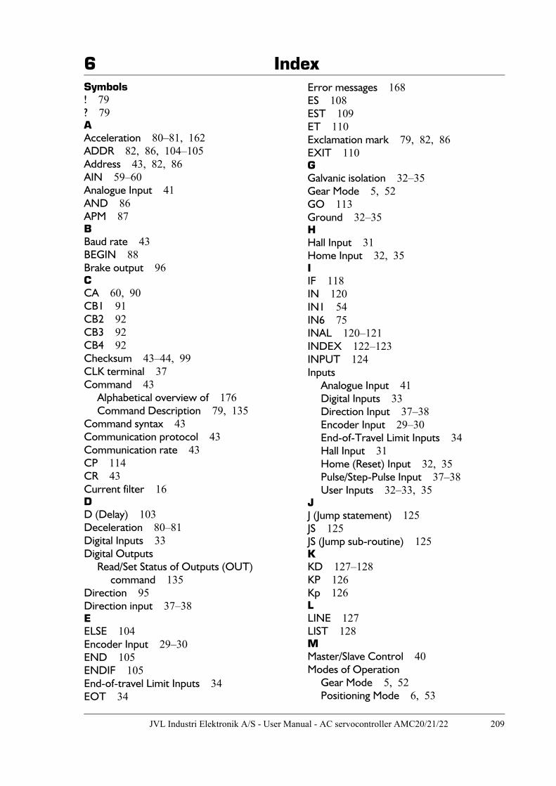
6 Index
JVL Industri Elektronik A/S - User Manual - AC servocontroller AMC20/21/22 209
Symbols! 79? 79AAcceleration 80–81, 162ADDR 82, 86, 104–105Address 43, 82, 86AIN 59–60Analogue Input 41AND 86APM 87BBaud rate 43BEGIN 88Brake output 96CCA 60, 90CB1 91CB2 92CB3 92CB4 92Checksum 43–44, 99CLK terminal 37Command 43
Alphabetical overview of 176Command Description 79, 135
Command syntax 43Communication protocol 43Communication rate 43CP 114CR 43Current filter 16DD (Delay) 103Deceleration 80–81Digital Inputs 33Digital Outputs
Read/Set Status of Outputs (OUT) command 135
Direction 95Direction input 37–38EELSE 104Encoder Input 29–30END 105ENDIF 105End-of-travel Limit Inputs 34EOT 34
Error messages 168ES 108EST 109ET 110Exclamation mark 79, 82, 86EXIT 110GGalvanic isolation 32–35Gear Mode 5, 52GO 113Ground 32–35HHall Input 31Home Input 32, 35IIF 118IN 120IN1 54IN6 75INAL 120–121INDEX 122–123INPUT 124Inputs
Analogue Input 41Digital Inputs 33Direction Input 37–38Encoder Input 29–30End-of-Travel Limit Inputs 34Hall Input 31Home (Reset) Input 32, 35Pulse/Step-Pulse Input 37–38User Inputs 32–33, 35
JJ (Jump statement) 125JS 125JS (Jump sub-routine) 125KKD 127–128KP 126Kp 126LLINE 127LIST 128MMaster/Slave Control 40Modes of Operation
Gear Mode 5, 52Positioning Mode 6, 53
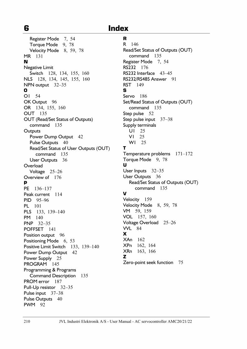
6 Index
210 JVL Industri Elektronik A/S - User Manual - AC servocontroller AMC20/21/22
Register Mode 7, 54Torque Mode 9, 78Velocity Mode 8, 59, 78
MR 131NNegative Limit
Switch 128, 134, 155, 160NLS 128, 134, 145, 155, 160NPN output 32–35OO1 54OK Output 96OR 134, 155, 160OUT 135OUT (Read/Set Status of Outputs)
command 135Outputs
Power Dump Output 42Pulse Outputs 40Read/Set Status of User Outputs (OUT)
command 135User Outputs 36
OverloadVoltage 25–26
Overview of 176PPE 136–137Peak current 114PID 95–96PL 101PLS 133, 139–140PM 140PNP 32–35POFFSET 141Position output 96Positioning Mode 6, 53Positive Limit Switch 133, 139–140Power Dump Output 42Power Supply 25PROGRAM 145Programming & Programs
Command Description 135PROM error 187Pull-Up resistor 32–35Pulse input 37–38Pulse Outputs 40PWM 92
RR 146Read/Set Status of Outputs (OUT)
command 135Register Mode 7, 54RS232 176RS232 Interface 43–45RS232/RS485 Answer 91RST 149SServo 186Set/Read Status of Outputs (OUT)
command 135Step pulse 52Step pulse input 37–38Supply terminals
U1 25V1 25W1 25
TTemperature problems 171–172Torque Mode 9, 78UUser Inputs 32–35User Outputs 36
Read/Set Status of Outputs (OUT) command 135
VVelocity 159Velocity Mode 8, 59, 78VM 59, 159VOL 157, 160Voltage Overload 25–26VVL 84XXAn 162XPn 162, 164XRn 163, 166ZZero-point seek function 75