Embed Size (px)
Citation preview
AdvisoryU.S. Department of Transportation Circular Federal Aviation Administration
Subject: Airport Avian Radar Systems Date: 11/23/10 AC No: 150/5220-25 Initiated by: AAS-100 Change:
1. PURPOSE. This advisory circular (AC) provides guidance on the use of avian radar systems to supplement an airport’s Wildlife Hazard Management Plan (WHMP) and reduce the potential avian threats to aircraft.
2. SCOPE. This AC describes how airports can select, procure, deploy, and manage an avian radar system. A chapter dedicated to each of the program areas is provided, as shown in the summaries below:
• Selection: Describes the factors that must be considered when choosing the proper system for a given set of airport conditions and requirements (Chapter 3).
• Procurement: The minimum performance standards for airport avian radar systems are provided (Chapter 4).
• Deployment: Discusses the process of installing a system in the location best suited to maximize system capabilities (Chapter 5).
• Management: Outlines the effective use of avian radar system data using the fundamental principles of risk management (Chapter 6).
The guidance in this AC is applicable to airport owners and operators. This AC is based on research conducted by the Federal Aviation Administration (FAA) Airport Technology Research and Development Program to examine the performance of several avian radar technologies.
3. APPLICATION. The Federal Aviation Administration (FAA) recommends the guidance and specifications in this Advisory Circular for deploying and managing an avian radar system at an airport. In general, use of this AC is not mandatory. However, use of this AC is mandatory for all projects funded with federal grant monies through the Airport Improvement Program (AIP) and with revenue from the Passenger Facility Charge (PFC) Program. See Grant Assurance No. 34, Policies, Standards, and Specifications, and PFC Assurance No.9, Standards and Specifications.
AC 150/5220-25 11/23/10
4. COMMENTS OR SUGGESTIONS for improvements to this AC should be sent to:
Manager, Airport Engineering Division (AAS-100) ATTN: AVIAN RADAR Federal Aviation Administration 800 Independence Avenue SW Washington DC 20591
Michael J. O'Donnell Director of Airport Safety and Standards
ii
11/23/10 AC 150/5220-25
TABLE OF CONTENTS
CHAPTER 1. TERMINOLOGY AND REFERENCES ........................................................... 5 1.1. Definitions............................................................................................................... 5 1.2. Acronyms and Terms.............................................................................................. 6 1.3. Applicable Documents............................................................................................ 7
CHAPTER 2. INTRODUCTION................................................................................................ 9 2.1. General.................................................................................................................... 9 2.2. System Benefits and Limitations. ........................................................................... 9 2.3. Wildlife Hazard Regulatory Issues. ...................................................................... 10 2.4. Avian Radar Fundamentals................................................................................... 11 2.5. System Implementation Overview........................................................................ 14
CHAPTER 3. SYSTEM SELECTION ..................................................................................... 17 3.1. General.................................................................................................................. 17 3.2. Bird Movement Patterns and Radar Coverage Area............................................. 17 3.3. Equipment Considerations. ................................................................................... 18 3.4. Data Acquisition and Management Considerations.............................................. 19 3.5. Additional System Considerations........................................................................ 19
CHAPTER 4. PERFORMANCE SPECIFICATIONS ........................................................... 21 4.1. Fundamental Standards......................................................................................... 21 4.2. Detection Performance.......................................................................................... 21 4.3. Signal Standards.................................................................................................... 23 4.4. Data Standards. ..................................................................................................... 23 4.5. Data Presentation / Display Standards.................................................................. 24
CHAPTER 5. DEPLOYMENT ................................................................................................. 27 5.1 General.................................................................................................................. 27 5.2. Site Selection. ....................................................................................................... 27 5.3. Equipment Setup and Initial Operation................................................................. 34 5.4. Integration into Airport Operations. ..................................................................... 36
CHAPTER 6. OPERATIONS AND MANAGEMENT........................................................... 37 6.1. General.................................................................................................................. 37 6.2. Applications. ......................................................................................................... 37 6.3. Data Acquisition and Use. .................................................................................... 38 6.4. Data analysis and the Risk Assessment Process. .................................................. 43 6.5. Continuous Program Improvement....................................................................... 43
APPENDIX A. ADDITIONAL SYSTEM STANDARDS. ...................................................... 45
iii
AC 150/5220-25 11/23/10
LIST OF FIGURES
Figure 2-1. Basic Radar System Components ............................................................................. 11 Figure 2-2. A Radar Operational Console ................................................................................... 12 Figure 2-3. Slotted Array Antenna............................................................................................... 13 Figure 2-4. Parabolic Dish Antenna............................................................................................. 13 Figure 2-5. Radar DRSP Detected Movements on a Geographically Referenced Screen........... 14 Figure 5-1. Areas of Higher and Lower Levels of Bird Activity by Month................................ 29 Figure 5-2. Seasonal Changes in the Numbers of Birds .............................................................. 30 Figure 5-3. Land Cover Types ..................................................................................................... 30 Figure 5-4. Attractive Habitats Showing Threats ........................................................................ 31 Figure 5-5. Radar Tracks Showing Expected Arrival and Departure Paths of Aircraft (Colors
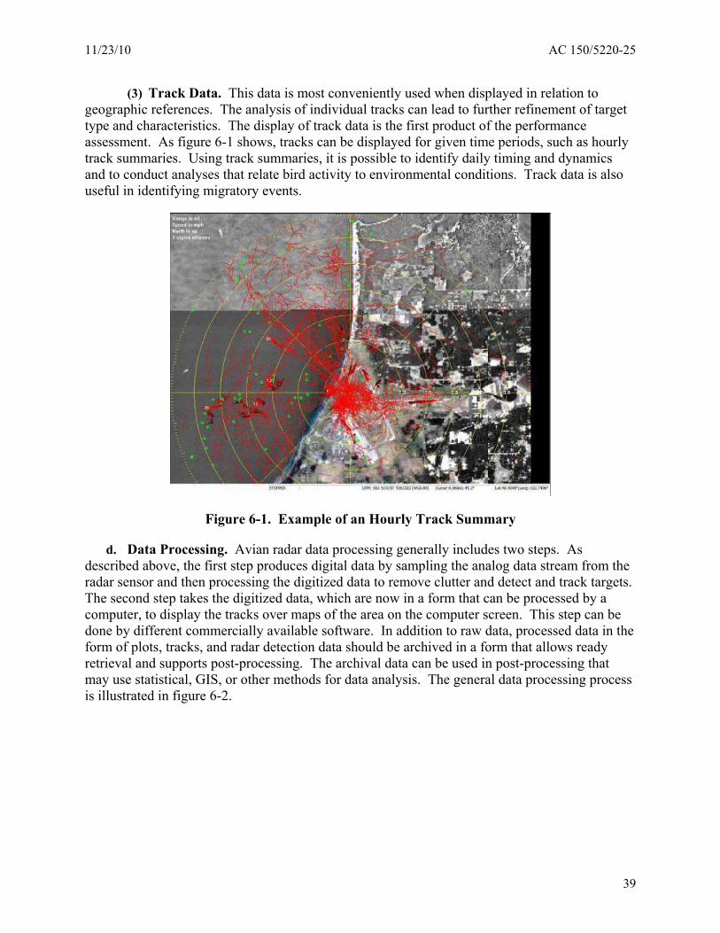
Indicate Altitude) .................................................................................................. 32 Figure 6-1. Example of an Hourly Track Summary .................................................................... 39 Figure 6-2. Flowchart of Radar Data Processing......................................................................... 40 Figure 6-3. Flowchart of Radar Raw Data Processing With DRSP ............................................ 41 Figure 6-4. Flowchart of Data Product Generation ..................................................................... 41
LIST OF TABLES
Table 4-1. Parameters recorded for each update (scan) of each tracked target. .......................... 25
iv
11/23/10 AC 150/5220-25
CHAPTER 1. TERMINOLOGY AND REFERENCES
1.1. DEFINITIONS.
a. Air Operations Area (AOA). All airport areas where aircraft can operate, either under their own power or while in tow. The AOA includes runways, taxiways, apron areas, and all unpaved surfaces within the airport’s perimeter fence.
b. Airport Apron (or Ramp). A surface in the AOA where aircraft park and are serviced (refueled, loaded with cargo, and/or boarded by passengers).
c. Avian Radar System. An avian radar system that integrates sensor data, data processing (including digitization), data management, and data display.
d. B-scan. Bearing scan designed to convert a polar-sampled image into a Cartesian format while retaining integrity of the geometry and content of the image. In radar this provides range, azimuth, and intensity data from radar in Cartesian coordinates.
e. Clutter. Undesired echoes returned from radar transmissions.
f. dBm2. Decibel meter-squared, a unit of measure for the radar cross section of a target:
RCS (dBm2) = 10·log10(σ/1 m2)
g. False negative. Failure to declare a target when a target is actually present, or failing to provide an alert, when a target alert is warranted.
h. False positive. Declaring a target, or providing an alert, when no target is present.
i. Hazard. A condition, object or activity with the potential for causing damage, loss, or injury.
j. L-band. Radar frequency in the 1-2 Ghz range, typical wavelength 23 cm.
k. Manufacturer. The manufacturer, distributor, lessor, or supplier of an avian radar system and/or associated support equipment. This includes any provider of an airport’s WHMP that incorporates an avian radar system.
l. Radio signal. Electro-magnetic radiation consisting of a defined frequency and/or waveform.
m. Real-time. The update of data before the completion of the next scan of the radar, providing a steady flow of information to the user.
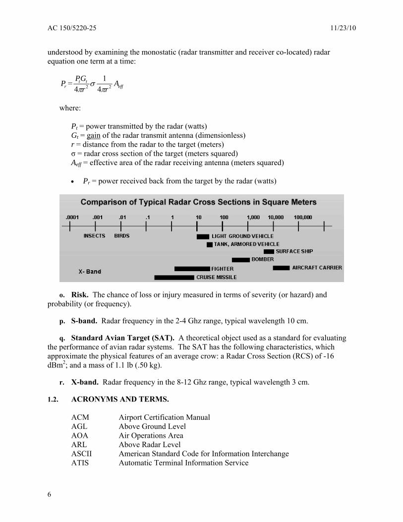
n. RCS. Radar cross section, a measure of target reflectivity based on the power equation: RCS of a radar target is the hypothetical area required to intercept the transmitted power density at the target such that if the total intercepted power were re-radiated isotropically, the power density actually observed at the receiver is produced. This is a complex statement that can be
5
AC 150/5220-25 11/23/10
understood by examining the monostatic (radar transmitter and receiver co-located) radar equation one term at a time:
PG 1P = t t σ Ar 2 2 eff4πr 4πr
where:
Pt = power transmitted by the radar (watts) Gt = gain of the radar transmit antenna (dimensionless) r = distance from the radar to the target (meters) σ = radar cross section of the target (meters squared) Aeff = effective area of the radar receiving antenna (meters squared)
• Pr = power received back from the target by the radar (watts)
o. Risk. The chance of loss or injury measured in terms of severity (or hazard) and probability (or frequency).
p. S-band. Radar frequency in the 2-4 Ghz range, typical wavelength 10 cm.
q. Standard Avian Target (SAT). A theoretical object used as a standard for evaluating the performance of avian radar systems. The SAT has the following characteristics, which approximate the physical features of an average crow: a Radar Cross Section (RCS) of -16 dBm2; and a mass of 1.1 lb (.50 kg).
r. X-band. Radar frequency in the 8-12 Ghz range, typical wavelength 3 cm.
1.2. ACRONYMS AND TERMS.
ACM Airport Certification Manual AGL Above Ground Level AOA Air Operations Area ARL Above Radar Level ASCII American Standard Code for Information Interchange ATIS Automatic Terminal Information Service
6
11/23/10 AC 150/5220-25
COTS Commercial Off-The-Shelf dBm2 Decibel per Square Meter DRSP Digital Radar Signal Processor FAA Federal Aviation Administration GHz 109 Cycles per Second GIS Geographic Information System GMT Greenwich Mean Time; see also UTC GPS Global Positioning System ICAO International Civil Aviation Organization KML Keyhole Markup Language LAN Local Area Network nmi Nautical Mile PPI Plan Position Indicator RCS Radar Cross Section RDBMS Relational Database Management System RF Radio Frequency SSL Secure Sockets Layer TDV Track Data Viewer TDWR Terminal Doppler Weather Radar TVW Track Viewer Workstation UPS Uninterruptable Power Supply UTC Coordinated Universal Time WGS84 World Geodetic System, 1984 Revision
1.3. APPLICABLE DOCUMENTS.
The following documents form part of this specification and are applicable to the extent specified:
a. FAA Orders, Specifications, Drawings, and Advisory Circulars (ACs).
AC 150/5200-18 Airport Safety Self-Inspection
AC 150/5200-32 Reporting Wildlife Aircraft Strikes
AC 150/5200-33 Hazardous Wildlife Attractants On or Near Airports
AC 150/5300-13 Airport Design
Order JO 7110.65 Air Traffic Control, Bird Activity Information
AIM, Section 7-4-6 Aeronautical Information Manual: Official Guide to Basic Flight Information and ATC Procedures. Flights Over Charted U.S. Wildlife Refuges, Parks, and Forest Service Areas
7
AC 150/5220-25 11/23/10
b. Industry Publications.
Dolbeer, R.A., et al. Wildlife Strikes to Civil Aircraft in the United States
Gauthreaux, S.A., et al. Overview: Radar Ornithology and Biological Conservation
Skolnik, M.I., ed. Radar Handbook
c. Sources.
(1) FAA ACs may be obtained from the FAA website at: http://www.faa.gov/regulations_policies/advisory_circulars/
(2) FAA Orders, Specifications, and Drawings may be obtained from: Federal Aviation Administration, ATO-W CM-NAS Documentation, Control Center, 800 Independence Avenue, SW, Washington, DC 20591. Telephone: (202) 548-5256, FAX: (202) 548-5501 and website: http://www.faa.gov/about/office_org/headquarters_offices/ato/service_units/techops/atc_facilitie s/cm/cm_documentation/
(3) Dolbeer, R.A., Wright, S.E., Weller, J., and Begier, M.J., Wildlife strikes to civil aircraft in the United States 1990-2008. 2009.
(4) Gauthreaux, S.A., JR. and Belser, C. G., Overview: Radar Ornithology and Biological Conservation. Auk 120:266-277, 2003.
(5) Skolnik, M. I., ed., Radar Handbook, Second Edition, McGraw-Hill, New York, 1990, pp. 6.8.
8
11/23/10 AC 150/5220-25
CHAPTER 2. INTRODUCTION
2.1. GENERAL.
Wildlife hazards include many different species of animals with birds the most common hazard and the primary focus of aviation safety. The proper management of birds on and around airports can do much to reduce the risk of bird strikes. In support of these goals, specific radar-based detection systems have been developed to support two critical efforts: the monitoring of bird movements in support of an airport’s WHMP and the surveillance of airspace to identify potential threats to the safe operation of aircraft.
2.2. SYSTEM BENEFITS AND LIMITATIONS.
a. Benefits. In the past, the only tool available at airports to perform these monitoring and surveillance tasks was limited to human observation by airport personnel. These individuals then had to manually document bird species and numbers and perform in-depth scientific investigations on the results to obtain useful, actionable, information. With the advent of radar technologies and the availability of relatively inexpensive radar systems, a new tool was introduced to airports to aid in their WHMP.
(1) Avian radar provides an opportunity to extend observational capabilities to aroundthe-clock operation and the ability to expand spatial coverage in both distance and altitude. For example, avian radars can be used in a surveillance mode for providing coverage of approach and departure corridors. This surveillance can improve the understanding of bird movement dynamics in critical corridors and help in assessing the real threat to aircraft safety posed by birds. Avian radar systems can also provide consistent information for trend assessments, identification of areas for focused management, and information about active wildlife management efforts at the airport.
b. Limitations. The successful use of avian radars requires a clear understanding of the system’s capabilities and limitations. The two primary limitations occur as a result of the physics underlying the transmission and reception of the radar pulse. The first phenomena include the generation of erroneous returns, or echoes, and the second phenomena involves the time-delay observed during object detection. A radar operator must have a clear understanding of what the radar is “seeing” to distinguish bird tracks from tracks produced by insects, airport vehicles, multiple echoes, or objects no longer in the expected position due to time-lag.
(1) Erroneous returns. The physics of the RF signal, the transmission characteristics of that signal, the antenna that sends and receives the signal, and the sensitivity of the receiver all influence detection capability and the tracking of targets. Unpredictable data can sometimes be generated and are exhibited when large targets are detected well outside a radar antenna’s expected beam geometry, and energies from the beam (due to side-lobe energies) sometimes create echoes from unexpected places. Other types of interference can occur during the movement of large aircraft on the ground at slow speeds, which can produce multiple echoes (multipath interference) and potentially misleading track information.
(2) Time-delay. Avian radar has time limitations in terms of response times for target identification and tracking. Because the technology relies on a rotating beam and computer
9
AC 150/5220-25 11/23/10
computations, there are lags between an echo return, detection, and eventual display. Users must be aware that a displayed target may no longer be in the location identified by the radar at that time. For example, the relative closing velocity of a bird and an aircraft is very rapid. A closing velocity of 250 mph covers a distance of over 350 ft, the length of a football field, in a second. If the antenna is rotating 24 times a minute, once every 2.5 seconds, and there is time needed for digital processing, a 3- or 4-second delay in target acquisition translates to a 1/4 mile of distance traveled by an aircraft.
(3) Site limitations. The construction requirements on airports present limitations on where the radar system can be installed. Since safety areas are critical areas where obstructions to aircraft must be limited, installations in the most ideal locations to maximize performance may not be possible. Radar technologies are also bound by physical laws that require line-of-site positioning and adjustment of radar radio frequency (RF) characteristics to the airport environment where multiple permanent and mobile reflectors of RF energy challenge the interpretation of radar information.
2.3. WILDLIFE HAZARD REGULATORY ISSUES.
Note: This section is provided as guidance only, and does not mandate the use of avian radar systems.
a. The need for wildlife hazard management at certificated airports is based on the requirements outlined in 14 CFR Part 139, Certification of Airports. The presence of birds in the airport environment is discussed in §139.337, and if certain conditions are met, requires airports to conduct a wildlife hazard assessment (WHA) and/or implement a WHMP. Both the assessment and management plans require the observation of bird populations and types that pose a threat to aircraft. It should be noted that while Part 139 requirements are mandatory for a holder of a Part 139 Airport Operating Certificate, the regulation contains many safety practices the FAA recommends for use at all airports.
b. Other FAA guidance documents, such as the Bird Activity Information section (2-1-22) of FAA Order JO 7110.65S Air Traffic Control, tasks air traffic controllers to issue advisory information on "pilot-reported, tower-observed or radar-observed and pilot-verified" bird activities. Also, the FAA Aeronautical Information Manual: Official Guide to Basic Flight Information and ATC Procedures (AIM), Section 7-4-6, Flights Over Charted U.S. Wildlife Refuges, Parks, and Forest Service Areas, details current FAA procedures regarding wildlife hazards. Current instructions to pilots focus on general awareness of possible wildlife hazards and protocols for dealing with wildlife encounters that threaten the aircraft. AIM directs pilots to reduce bird strike risks through (1) avoidance, through the implementation of strategies such as minimizing en-route flight at lower elevations during migratory months, avoiding over flight of known areas of bird concentration, and climbing to avoid collision with birds encountered en route, and (2) review of emergency procedures for wildlife encounters that threaten aircraft, including engine ingestion, engine-out, and windshield strike. AIM also notes that pilots may be advised of bird activity at specific airports through the Airport/Facility Directory and the NOTAM system.
10
11/23/10 AC 150/5220-25
2.4. AVIAN RADAR FUNDAMENTALS.
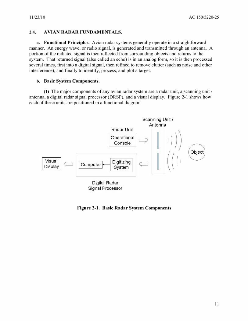
a. Functional Principles. Avian radar systems generally operate in a straightforward manner. An energy wave, or radio signal, is generated and transmitted through an antenna. A portion of the radiated signal is then reflected from surrounding objects and returns to the system. That returned signal (also called an echo) is in an analog form, so it is then processed several times, first into a digital signal, then refined to remove clutter (such as noise and other interference), and finally to identify, process, and plot a target.
b. Basic System Components.
(1) The major components of any avian radar system are a radar unit, a scanning unit / antenna, a digital radar signal processor (DRSP), and a visual display. Figure 2-1 shows how each of these units are positioned in a functional diagram.
Figure 2-1. Basic Radar System Components
11
AC 150/5220-25 11/23/10
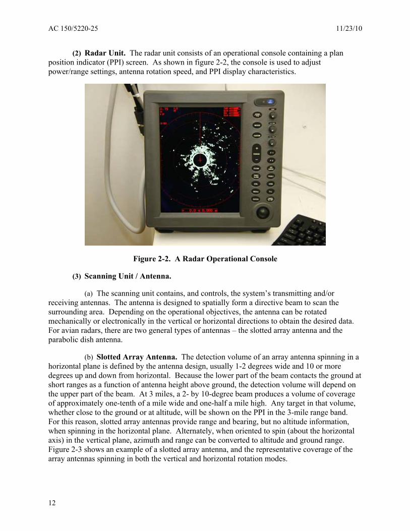
(2) Radar Unit. The radar unit consists of an operational console containing a plan position indicator (PPI) screen. As shown in figure 2-2, the console is used to adjust power/range settings, antenna rotation speed, and PPI display characteristics.
Figure 2-2. A Radar Operational Console
(3) Scanning Unit / Antenna.
(a) The scanning unit contains, and controls, the system’s transmitting and/or receiving antennas. The antenna is designed to spatially form a directive beam to scan the surrounding area. Depending on the operational objectives, the antenna can be rotated mechanically or electronically in the vertical or horizontal directions to obtain the desired data. For avian radars, there are two general types of antennas – the slotted array antenna and the parabolic dish antenna.
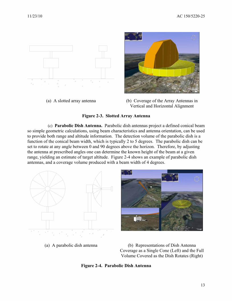
(b) Slotted Array Antenna. The detection volume of an array antenna spinning in a horizontal plane is defined by the antenna design, usually 1-2 degrees wide and 10 or more degrees up and down from horizontal. Because the lower part of the beam contacts the ground at short ranges as a function of antenna height above ground, the detection volume will depend on the upper part of the beam. At 3 miles, a 2- by 10-degree beam produces a volume of coverage of approximately one-tenth of a mile wide and one-half a mile high. Any target in that volume, whether close to the ground or at altitude, will be shown on the PPI in the 3-mile range band. For this reason, slotted array antennas provide range and bearing, but no altitude information, when spinning in the horizontal plane. Alternately, when oriented to spin (about the horizontal axis) in the vertical plane, azimuth and range can be converted to altitude and ground range. Figure 2-3 shows an example of a slotted array antenna, and the representative coverage of the array antennas spinning in both the vertical and horizontal rotation modes.
12
11/23/10 AC 150/5220-25
(a) A slotted array antenna (b) Coverage of the Array Antennas in Vertical and Horizontal Alignment
Figure 2-3. Slotted Array Antenna
(c) Parabolic Dish Antenna. Parabolic dish antennas project a defined conical beam so simple geometric calculations, using beam characteristics and antenna orientation, can be used to provide both range and altitude information. The detection volume of the parabolic dish is a function of the conical beam width, which is typically 2 to 5 degrees. The parabolic dish can be set to rotate at any angle between 0 and 90 degrees above the horizon. Therefore, by adjusting the antenna at prescribed angles one can determine the known height of the beam at a given range, yielding an estimate of target altitude. Figure 2-4 shows an example of parabolic dish antennas, and a coverage volume produced with a beam width of 4 degrees.
(a) A parabolic dish antenna (b) Representations of Dish Antenna Coverage as a Single Cone (Left) and the Full Volume Covered as the Dish Rotates (Right)
Figure 2-4. Parabolic Dish Antenna
13
AC 150/5220-25 11/23/10
(4) Digital Radar Signal Processor (DRSP).
(a) The Digital Radar Signal Processor (DRSP) is the core of the modern avian radar system. Components include a digitizing system to transform the analog signal data into digital data, and a computer that uses the digitized data to reject clutter, process target detections, and plot target tracks. The presentation of radar data achieved by the DRSP allows an operator to analyze and interpret radar information.
(5) Visual Display.
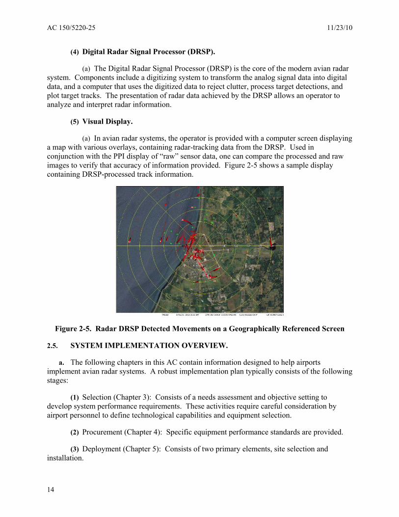
(a) In avian radar systems, the operator is provided with a computer screen displaying a map with various overlays, containing radar-tracking data from the DRSP. Used in conjunction with the PPI display of “raw” sensor data, one can compare the processed and raw images to verify that accuracy of information provided. Figure 2-5 shows a sample display containing DRSP-processed track information.
Figure 2-5. Radar DRSP Detected Movements on a Geographically Referenced Screen
2.5. SYSTEM IMPLEMENTATION OVERVIEW .
a. The following chapters in this AC contain information designed to help airports implement avian radar systems. A robust implementation plan typically consists of the following stages:
(1) Selection (Chapter 3): Consists of a needs assessment and objective setting to develop system performance requirements. These activities require careful consideration by airport personnel to define technological capabilities and equipment selection.
(2) Procurement (Chapter 4): Specific equipment performance standards are provided.
(3) Deployment (Chapter 5): Consists of two primary elements, site selection and installation.
14

11/23/10 AC 150/5220-25
(4) Operation and Data Analysis (Chapter 6): Contains information on the typical applications of avian radar systems in the airport environment, an overview of data usage and analysis, and suggestions for continuous program improvement.
15

AC 150/5220-25 11/23/10
This page intentionally left blank.
16
11/23/10 AC 150/5220-25
CHAPTER 3. SYSTEM SELECTION
3.1. GENERAL.
a. There are many considerations that will influence the type of avian radar system used at an airport. A basic understanding of the main considerations, including bird movement patterns, radar coverage area, equipment components, and data acquisition and management, allow an airport to select a system that is maximized to their unique geographic and operational situation.
b. The implementation of an avian radar system at a civil airport is a complex undertaking that includes preliminary site selection decisions, actual deployment, operations, maintenance, data analysis, management, and information dissemination. Airport operators must recognize that these actions require close coordination with trained wildlife biologists or other wildlife management professionals. The significant costs needed for wildlife personnel to support avian radar systems, including the operation and maintenance costs of the equipment itself, must also be considered by an airport during the system selection process.
3.2. BIRD MOVEMENT PATTERNS AND RADAR COVERAGE AREA.
a. True regional coverage requires an integrated network of avian radars, which unfortunately, is challenging given current technology and information coordination limitations. To focus on the actual area that can be studied with equipment operated directly by airports, the following bird patterns and corresponding coverage areas are provided as a general guide. It should be noted that all of the following types of birds that approach the airport can be picked up by avian radars within the airport coverage area, providing local situational awareness of migrating, commuting, and resident birds.
(1) Migrating Birds / Regional Radar Coverage.
(a) Migrating birds move seasonally over long distances. Typically migrations occur below 5000 ft, but migrating birds may be present at altitudes in excess of 10,000 ft.
(b) Regional Coverage - Regional radar coverage allows for the detection of migrating birds, which can detect the flight altitudes and relative density of birds at those altitudes. At present, Terminal Doppler and Next Generation Weather Radars can provide this coverage, and research is continuing on the interpretation of bird migrations using these radars. The detection of migrating birds requires radar that can scan a hundred or more miles to altitudes in excess of 10,000 ft. Multiple radars may be needed for regional coverage.
(2) Commuting Birds / Local Radar Coverage.
(a) Local commuting birds show daily movement patterns in local (airport) to regional scales (5 to 20 miles from an airport). Commuters will move from roosting and loafing sites to feeding locations at altitudes from ground level to several thousand feet.
(b) Local Coverage - A regional radar can provide needed information for in-transit aircraft and warnings about potential conflicts with aircraft. The radar capabilities required include altitude discrimination and systems support to identify and track threats to an airport's
17
AC 150/5220-25 11/23/10
defined approach and departure paths. To detect commuting birds, local radar systems must be able to effectively scan altitudes up to several thousand feet to a range of 10 to 20 miles.
(3) Resident Birds / Airport Radar Coverage.
(a) Resident birds remain local to a site and may nest or roost on or near airports. Resident birds forage locally and typically fly under 1000 ft., although soaring birds may reach high altitudes.
(b) Airport Coverage – Strike data indicate that 90% or more of bird strikes occur below 3000 ft AGL, and 80% occur on or near the airport surface (Dolbeer, R. A. 2006). Aircraft taking off and landing are therefore the most vulnerable to bird strikes. Current avian radar technology can produce bird movement data that can be used at all levels of airport operations to mitigate the various threats posed by birds. Airport radar systems should be able to scan from the ground to several thousand feet, up to a range of several miles.
3.3. EQUIPMENT CONSIDERATIONS.
a. Marine Radar Technology.
(1) The most common avian radar systems use readily available marine band radar technology (S-band and X-band) with scan configurations and digital processing of sensor data optimized for the detection and tracking of birds. Although marine radar technology was originally designed to detect and track large, slow-moving targets on a flat surface, it has benefited from advances in electronics and the availability of low-cost digital processing.
(2) The use of marine radars as the basis for avian radar systems brings compromises in technological capabilities based on the cost and availability of off-the-shelf sensors. However, even as improvements are being made that will improve price and performance relationships of radar feature sets, there will always be price/performance trade-off that yields strengths in some areas and potential compromises in others. Airports should therefore understand the price/performance characteristics of the different avian radar systems they are considering.
b. Radar Unit. A component of this selection includes choices of radar transmission power, control sophistication, and potential conflicts of radar RF emissions at the airport. Avian radar manufacturers can accommodate specific needs, but additional planning and cost may be associated with meeting such needs.
c. Scanning Unit / Antenna. Antenna selection is one of the most important decisions that can be made in implementing an avian radar system. The antenna type (array or parabolic dish) determines the operational characteristics of the radar (e.g., volume coverage) as well as the response of the system to clutter interference. The type of antenna should be selected by considering coverage needs and volumes of detection as constrained by clutter based on radar location. The importance of the availability of coarse altitude information for targets should also be considered.
d. DRSP. Avian radars generally provide only limited information beyond range, direction of movement, and velocity. It is the interpretation and application of that information to specific
18
11/23/10 AC 150/5220-25
operational objectives that gives radar its value. Unfortunately, manufacturers each have their own proprietary processing equipment, software, and algorithms to process raw signal data to obtain optimum results. Airports must be aware of the capabilities and limitations provided by each proprietary system.
e. Visual Displays. A wide range of options exists for the display of radar data. Typical display options provide target tracking with system capabilities to count tracks, summarize data, and then display results in either real time or as historical summaries. In terms of the actual display equipment, there are a variety of display sizes and colors to consider depending on the intended applications.
3.4. DATA ACQUISITION AND MANAGEMENT CONSIDERATIONS.
a. The quality of the data provided by an avian radar system is the most important factor in data acquisition and management. After quality, factors such as data geographic references, the time interval between data generation, analysis, and reporting are important. In addition, a radar system’s data management program should reflect the results of an airport’s needs analysis and statement of objectives.
b. Data storage and retrieval is essential for the comparative analysis of movement dynamics. Data from specified time periods, such as hourly or daily summaries of bird movements, must be readily connected to the data archive in order to provide comprehensive database searches. Radars generate very large data sets, and the user will need to use the data management tools (e.g., database management systems, or DBMS) that accommodate these large data sets in order to facilitate data post-processing. Moreover, different post-processing applications may require different views of the same data. Usually, the radar system manufacturer will have developed unique analytical methods to analyze and view the collected data, and those methods should be considered in relation to the specific needs of the airport.
3.5. ADDITIONAL SYSTEM CONSIDERATIONS.
a. Each airport will have unique needs and requirements for an avian radar system to fulfill. A wide range of pricing and performance options are currently available. The selection of those options will be driven by the considerations previously mentioned in this Chapter, along with the following factors:
(1) Local and regional geography (such as the proximity to bodies of water, where wave action can produce clutter),
(2) Number, types, and movement patterns of bird species,
(3) Number and type of aircraft operating,
(4) Number and size of surveillance areas,
(5) Location of surveillance areas (and their horizontal/vertical distance from the sensor),
(6) Radar precision/sensitivity,
19

AC 150/5220-25 11/23/10
(7) Radar maintenance requirements,
(8) Airport climate (sensors generally operate most effectively under clear and dry conditions - heavy rainfall or snow can degrade sensor effectiveness), and
(9) Ability of personnel to respond to alerts.
20
11/23/10 AC 150/5220-25
CHAPTER 4. PERFORMANCE SPECIFICATIONS
4.1. FUNDAMENTAL STANDARDS.
a. Basic Functions. Avian radar systems must perform the following functions:
(1) Detect the movement of standard bird targets at ranges and altitudes appropriate for the sensor and as specified by the airport.
(2) Plot detected targets in a coordinate system and assemble sequential plots into tracks.
(3) Operate in conjunction with, and not interfere with, airport and aircraft communication, navigation, and surveillance systems.
(4) Operate in conjunction with, and without interference from, normal airport and aircraft operations (e.g., aircraft and vehicle movements).
(5) Provide a data record of bird movements, allowing for equipment calibration and the analysis of events (including daily, seasonal, and annual activities).
(6) Support maintenance programs and periodic calibration and tuning.
b. Standard Avian Target (SAT).
(1) An SAT is a theoretical object used as a standard for evaluating the performance of avian radar systems. The SAT has the following characteristics, which approximate the physical features of an average crow:
(a) Radar Cross Section (RCS): -16 dBm2
(b) Mass: 1.1 lb (.50 kg)
(2) The SAT is defined under the following conditions: a bird in side (profile) view; moderate clutter environment (flat airport area, no rain); at 300 ft (91 m) in altitude; and in the middle of the radar beam.
(3) When multiples of the SAT are referenced, the RCS and mass quantities are increased or decreased accordingly. For example, a 2 SAT (or 2 times the Standard Avian Target) object has a mass of 2.2 lb and an RCS of -13 dBm2 (since doubling the intensity on a logarithmic scale equates to an increase of 3 dB). A 2 SAT object would therefore approximate the physical features of another common bird, the Mallard duck.
4.2. DETECTION PERFORMANCE.
a. Standard Object Detection. Avian radar systems must be able to detect the following targets at each of the ranges (from the sensor) specified:
(1) Range: 0.3 to 1 nmi (.6 to 2 km). Target: 1 SAT up to an altitude of 1000 ft (300 m) (ARL).
21
AC 150/5220-25 11/23/10
(2) Range: 0.3 to 3 nmi (.6 to 6 km). Target: at least 2 SAT up to an altitude of 3000 ft (900 m) (ARL).
b. Multiple Objects. Avian radar systems must be capable of tracking at least 1000 targets, simultaneously.
c. Object Resolution. Avian radar systems must be capable of differentiating two standard avian targets when separated by 165 ft (50.0 m) or less in both range and azimuth (cross-range) at a range of up to 1.0 nmi (1.9 km).
d. Surveillance Area. At a minimum, avian radar systems must be able to provide coverage of the airspace defined by the flight path of the airport’s primary runway (for both landing and takeoff), up to 3 nmi (6 km) from the sensor location and up to 3000 ft (900 m) in elevation (at 5 nm / 9 km). The specific areas/volumes of coverage, must be defined by the manufacturer for each location. Additional surveillance areas (based on the airport’s WHMP) may be specified by the airport operator.
e. Location Accuracy. Avian radar systems must provide range location information for a tracked target that is within 165 ft (50.0 m) of the actual target’s range location.
f. Detection Quality. Avian radar systems must be capable of the detecting an SAT at the following ranges and confidence levels:
(1) up to 1.0 nmi (1.9 km) from the sensor with a confidence level of 90% in moderate clutter environments (flat airport area, no rain);
(2) from 1.0 to 3.0 nmi (1.9 to 5.6 km) from the sensor with a confidence level of 75% in moderate clutter environments (flat airport area, no rain);
Note: The manufacturer is free to develop or use any method to demonstrate that the performance of their system meets the required confidence levels.
g. Inspection Frequency. Avian radar systems must be capable of continuous operation to allow for the continuous inspection of the surveillance areas airspace during flight operations. The time interval between successive updates for the position of a tracked SAT must not exceed 5 seconds. The duration of flight operations is dependent on the airport and specified by the user.
h. Detection Response Time. Avian radar systems must have the capability to acquire an SAT located in the surveillance area within 5 seconds of the area being scanned.
i. Weather. Avian radar systems must demonstrate the detection performance under both clear and inclement weather conditions.
(1) Demonstrate detection capabilities under rainfall or snow conditions (e.g. having a specific intensity, duration, and frequency) for a two-year category of storm in the local region (as specified in CLIM 20, Climatology of the United States No. 20). Specific requirements must be specified by the user.
22
11/23/10 AC 150/5220-25
(2) Avian radar systems must have site-specific performance specifications that include validated:
(a) performance during clear weather conditions;
(b) performance during inclement weather conditions; and
(c) provide the airport operator with the amount of time required for the system to recover after a rain or snow storm, that is, to return the performance capabilities of clear weather conditions after adverse weather conditions subside. In this case, the end of adverse weather conditions will be defined as when precipitation of rain or snow ends.
(3) Lighting conditions. All systems must demonstrate detection performance during daylight, nighttime, and dawn/dusk operations.
4.3. SIGNAL STANDARDS.
a. Signal Generation. Both magnetron or solid state systems are acceptable.
b. Antenna configuration. Multiple antenna configurations are possible meeting site requirements (including either dish or slotted array antennas).
4.4. DATA STANDARDS.
a. Data Digitization (Analog to Digital Data Conversion).
(1) Fidelity. Analog radar echo signals must be converted to digital data with the fidelity of the digitized data to the analog signal known.
(2) Format. Digitized radar data converted in the B-scan or scan-converted format systems are acceptable.
(3) Multi-tasking. The system must be able to record B-scan or scan-converted data while not interfering with data processing (detection and tracking) or data recording (of the detections/plots and tracks). Thus, these processes must be able to occur simultaneously to allow constant observation of the displays.
b. Clutter Management.
(1) System processors must be able to provide the capability to identify clutter, map clutter locations, and address clutter influences on the detection of a target.
(2) The system must be able to detect and manage for improved clarity, false positive and false negative target detections. As a class of false positive detections, the system must be able to detect and manage for multipath interference and side lobe detections.
23
AC 150/5220-25 11/23/10
c. Data Storage and Archiving.
(1) Avian radar systems must be capable of recording at least one hour of raw digital data (in a B-scan and/or scan-converted format) to support reprocessing. Reprocessing may facilitate training, calibration and sensitivity testing, and wildlife management inquiries. In addition, the hardware and software tools required for reprocessing must be provided by the manufacturer.
(2) Avian radar systems must be capable of recording at least 24 hours of plot and track data, or regenerating plot and track data from the raw digital data. The ability to store and view any screen captures of plot and track displays is also required.
(3) In the reprocessing of plot and track data, avian radar systems must be capable of supporting analyses that change criteria for track display, that provide alternatives for track history displays, and that provide easy comparison of track histories over different time scales.
(4) Avian radar systems must allow the easy retrieval of archived plot and track data based on a given date and time.
(5) All stored data must contain the scan update rate used by the system.
(6) Any type of plot and track data able to be retrieved and displayed must be provided in a standard, non-proprietary format, such as video (e.g. .avi, mpeg, etc.), image format (e.g. .jpg, gif, etc.) and Google Earth utility (.kml).
4.5. DATA PRESENTATION / DISPLAY STANDARDS.
a. Plot and Track Parameters.
(1) The system must provide a display of detected avian targets as plotted bird detections or processor identified bird tracks;
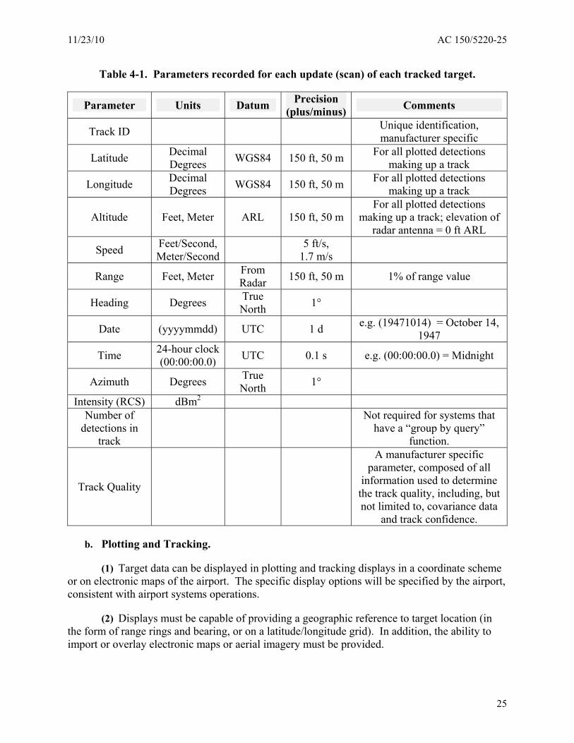
(2) Plotted bird detections and identified bird tracks must display the following data in a user-accessible format that include parameters in Table 4-1.
24
11/23/10 AC 150/5220-25
Table 4-1. Parameters recorded for each update (scan) of each tracked target.
Parameter Units Datum Precision (plus/minus) Comments
Track ID Unique identification, manufacturer specific
Latitude Decimal Degrees WGS84 150 ft, 50 m For all plotted detections
making up a track
Longitude Decimal Degrees WGS84 150 ft, 50 m For all plotted detections
making up a track
Altitude Feet, Meter ARL 150 ft, 50 m For all plotted detections
making up a track; elevation of radar antenna = 0 ft ARL
Speed Feet/Second, Meter/Second
5 ft/s, 1.7 m/s
Range Feet, Meter From Radar 150 ft, 50 m 1% of range value
Heading Degrees True North 1°
Date (yyyymmdd) UTC 1 d e.g. (19471014) = October 14, 1947
Time 24-hour clock (00:00:00.0) UTC 0.1 s e.g. (00:00:00.0) = Midnight
Azimuth Degrees True North 1°
Intensity (RCS) dBm2
Number of detections in
track
Not required for systems that have a “group by query”
function.
Track Quality
A manufacturer specific parameter, composed of all
information used to determine the track quality, including, but not limited to, covariance data
and track confidence.
b. Plotting and Tracking.
(1) Target data can be displayed in plotting and tracking displays in a coordinate scheme or on electronic maps of the airport. The specific display options will be specified by the airport, consistent with airport systems operations.
(2) Displays must be capable of providing a geographic reference to target location (in the form of range rings and bearing, or on a latitude/longitude grid). In addition, the ability to import or overlay electronic maps or aerial imagery must be provided.
25
AC 150/5220-25 11/23/10
(3) The system must provide information on the maximum number of tracks, track handling capacity, track storage procedures, and system saturation that limits track identification or storage.
(4) Multiple Sensor Integration. The system must have the ability to provide spatial and temporal alignment for the fusion of tracks from multiple sensors with overlapping coverage.
(5) The system must have the capability to record and compare “raw” radar sensor data (e.g. as shown on a PPI display) to the display produced by the radar digital signal processor. For systems that do not use a PPI-type display, a similar function must be provided to allow the user to conduct a quality assurance analysis of the plot and track information.
(6) The plot and track archive in any avian radar system must support easy access to historical data, support access by location, date, and time, and allow assembly of data sets for multiple locations, dates, or times. Note: For systems where the “plot” and “track” are considered to be the same entity, equivalent usage of that entity must be provided.
(7) Remote Use. If the optimal location of an avian radar system on an airport is in an area that prohibits regular access by system operators, the system must be capable for the remote operation, display, and recording of data when specified by the user.
(8) Options. The system should be able to provide the following options for target tracks:
(a) Target position coordinate system
(b) Track history display
(c) Total number of targets tracked per scan
c. Display Standards.
(1) The following tools and reference items must be provided on the user display, at a minimum:
(a) Distance measures and heading
(b) Units for on-screen measurements
26
11/23/10 AC 150/5220-25
CHAPTER 5. DEPLOYMENT
5.1 GENERAL.
a. Deploying an avian radar system consists of the following activities:
(1) Site Selection:
(a) Clutter Management / Mapping
(b) Bird Habitat / Critical Area Considerations
(c) Airspace Considerations
(d) Airport Installation Considerations
(2) Equipment Setup and Initial Operation
(3) Integration into Airport Operations
5.2. SITE SELECTION.
a. Although the primary objective for radar deployment is effective detection and tracking of targets, issues such as safety zones, power availability, network connectivity, and general access take precedence over optimal placement of radar. Placement of the radar on the airport invariably requires compromise in location.
b. Finding an acceptable site for the radar requires prioritizing identified needs and then carefully analyzing competing issues. From a radar operations perspective, the most critical criterion is minimizing clutter interference for critical areas. From a bird detection perspective, the most important criteria for site selection are providing good detection capabilities for known critical areas on the airport. Critical areas are those locations where observational data suggests a high hazard potential due to site attractants or the actual use of the area known from observations. These two factors can generally be accommodated by several locations. The final location is then determined by considering infrastructure needs, such as the enclosures needed for the radar system (including towers or other structures required for the radar antenna), power supply, and the availability of high-speed connectivity.
c. Clutter Management / Mapping.
(1) The beam patterns of both slotted array and parabolic dish antenna types produce reflections from ground surfaces, buildings, and other fixed targets that interfere with target detection and tracking. This “clutter environment” decreases the radar’s ability to detect and track avian targets. Thus, assessing the clutter environment when selecting a radar system is an important strategy for optimizing a radar’s effectiveness. Although experienced individuals can suggest locations based on “eyeball” surveys, the only way clutter is fully revealed is by operating the radar. This produces a difficult situation in the radar implementation process.
27
AC 150/5220-25 11/23/10
Using the radar on the airport requires the completion and approval of an FAA Form 7460 for the exact locations of the radar unit(s).
(2) A number of solutions have been found to this quandary. In some instances, temporary permission is granted for radar use during limited time periods. This facilitates the movement of the radar to multiple sites on the airport to provide actual data for possible alternative locations. After the temporary deployment of the radar, clutter mapping results can be reviewed and radar locations selected. If temporary permission is not available, airport personnel should use their judgment to select a small number of locations and submit FAA Form 7460 applications for each location. Deployment will be delayed if these initial locations are unacceptable, requiring testing of other locations. However, it is likely that one of the selected locations will meet minimal needs and full implementation can occur immediately after clutter mapping has been completed. Note: A review of any navigational aids located on an airfield should take place prior to the submission of a Form 7460. Navigational aids generally have minimum separation standards to other equipment in order to ensure that signal interference does not occur.
28
11/23/10 AC 150/5220-25
d. Bird Habitat / Critical Area Considerations.
(1) The location of possible sites can be determined using the records of wildlife managers to analyze the airport’s landscape and features to identify locations that may be attractive to birds. Such understanding of critical areas attractive to birds can be the basis for assessing needs and locating the radar to meet those needs. If an airport has performed a WHA or has a WHMP in place, many of these features may already be known. For those without a WHA or WHMP, several examples are described below.
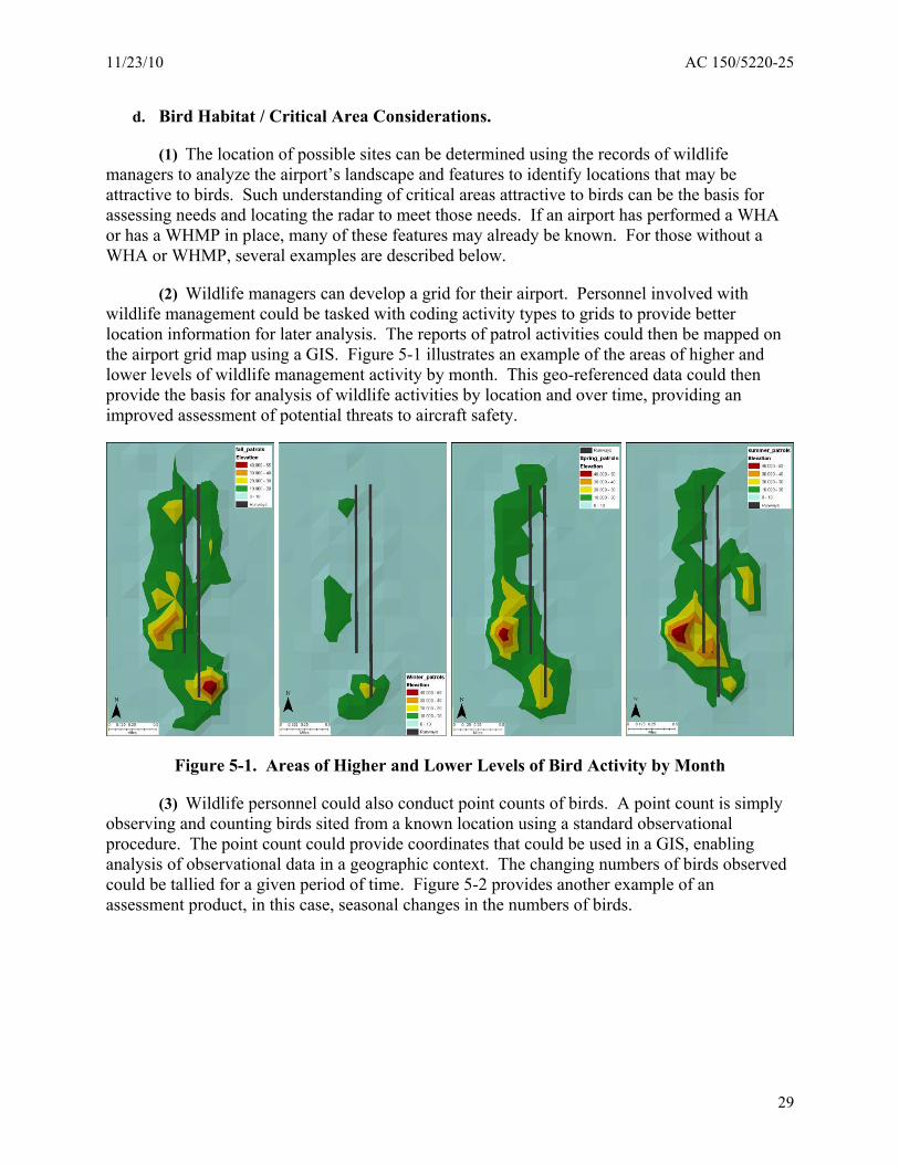
(2) Wildlife managers can develop a grid for their airport. Personnel involved with wildlife management could be tasked with coding activity types to grids to provide better location information for later analysis. The reports of patrol activities could then be mapped on the airport grid map using a GIS. Figure 5-1 illustrates an example of the areas of higher and lower levels of wildlife management activity by month. This geo-referenced data could then provide the basis for analysis of wildlife activities by location and over time, providing an improved assessment of potential threats to aircraft safety.
Figure 5-1. Areas of Higher and Lower Levels of Bird Activity by Month
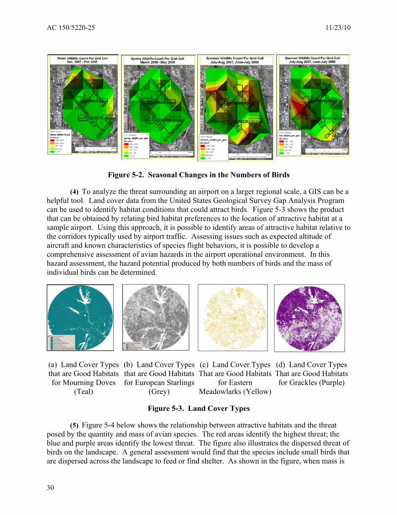
(3) Wildlife personnel could also conduct point counts of birds. A point count is simply observing and counting birds sited from a known location using a standard observational procedure. The point count could provide coordinates that could be used in a GIS, enabling analysis of observational data in a geographic context. The changing numbers of birds observed could be tallied for a given period of time. Figure 5-2 provides another example of an assessment product, in this case, seasonal changes in the numbers of birds.
29
(a) Land Cover Types that are Good Habitats for Mourning Doves
(Teal)
(b) Land Cover Types that are Good Habitats for European Starlings
(Grey)
(c) Land Cover Types That are Good Habitats
for Eastern Meadowlarks (Yellow)
(d) Land Cover Types That are Good Habitats for Grackles (Purple)
AC 150/5220-25 11/23/10
Figure 5-2. Seasonal Changes in the Numbers of Birds
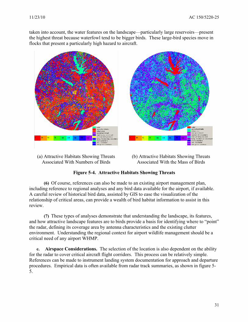
(4) To analyze the threat surrounding an airport on a larger regional scale, a GIS can be a helpful tool. Land cover data from the United States Geological Survey Gap Analysis Program can be used to identify habitat conditions that could attract birds. Figure 5-3 shows the product that can be obtained by relating bird habitat preferences to the location of attractive habitat at a sample airport. Using this approach, it is possible to identify areas of attractive habitat relative to the corridors typically used by airport traffic. Assessing issues such as expected altitude of aircraft and known characteristics of species flight behaviors, it is possible to develop a comprehensive assessment of avian hazards in the airport operational environment. In this hazard assessment, the hazard potential produced by both numbers of birds and the mass of individual birds can be determined.
Figure 5-3. Land Cover Types
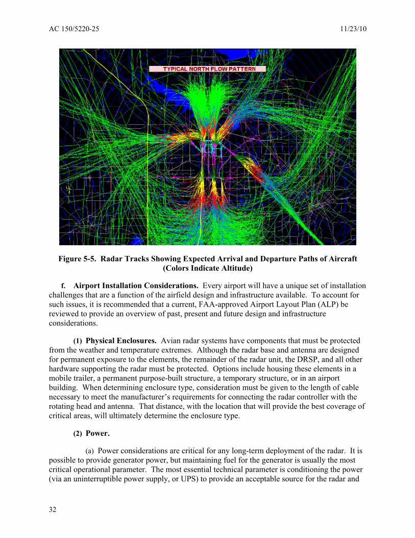
(5) Figure 5-4 below shows the relationship between attractive habitats and the threat posed by the quantity and mass of avian species. The red areas identify the highest threat; the blue and purple areas identify the lowest threat. The figure also illustrates the dispersed threat of birds on the landscape. A general assessment would find that the species include small birds that are dispersed across the landscape to feed or find shelter. As shown in the figure, when mass is
30
(a) Attractive Habitats Showing Threats Associated With Numbers of Birds
(b) Attractive Habitats Showing Threats Associated With the Mass of Birds
11/23/10 AC 150/5220-25
taken into account, the water features on the landscape—particularly large reservoirs—present the highest threat because waterfowl tend to be bigger birds. These large-bird species move in flocks that present a particularly high hazard to aircraft.
Figure 5-4. Attractive Habitats Showing Threats
(6) Of course, references can also be made to an existing airport management plan, including reference to regional analyses and any bird data available for the airport, if available. A careful review of historical bird data, assisted by GIS to ease the visualization of the relationship of critical areas, can provide a wealth of bird habitat information to assist in this review.
(7) These types of analyses demonstrate that understanding the landscape, its features, and how attractive landscape features are to birds provide a basis for identifying where to “point” the radar, defining its coverage area by antenna characteristics and the existing clutter environment. Understanding the regional context for airport wildlife management should be a critical need of any airport WHMP.
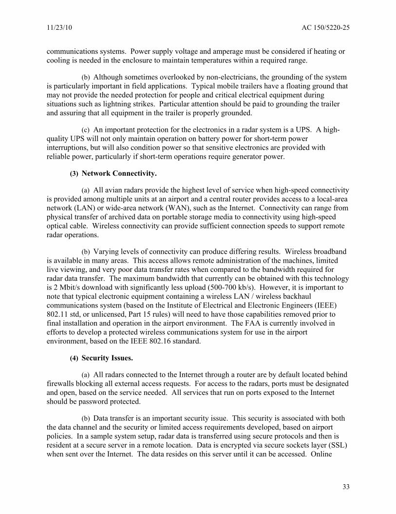
e. Airspace Considerations. The selection of the location is also dependent on the ability for the radar to cover critical aircraft flight corridors. This process can be relatively simple. References can be made to instrument landing system documentation for approach and departure procedures. Empirical data is often available from radar track summaries, as shown in figure 55.
31
AC 150/5220-25 11/23/10
Figure 5-5. Radar Tracks Showing Expected Arrival and Departure Paths of Aircraft (Colors Indicate Altitude)
f. Airport Installation Considerations. Every airport will have a unique set of installation challenges that are a function of the airfield design and infrastructure available. To account for such issues, it is recommended that a current, FAA-approved Airport Layout Plan (ALP) be reviewed to provide an overview of past, present and future design and infrastructure considerations.
(1) Physical Enclosures. Avian radar systems have components that must be protected from the weather and temperature extremes. Although the radar base and antenna are designed for permanent exposure to the elements, the remainder of the radar unit, the DRSP, and all other hardware supporting the radar must be protected. Options include housing these elements in a mobile trailer, a permanent purpose-built structure, a temporary structure, or in an airport building. When determining enclosure type, consideration must be given to the length of cable necessary to meet the manufacturer’s requirements for connecting the radar controller with the rotating head and antenna. That distance, with the location that will provide the best coverage of critical areas, will ultimately determine the enclosure type.
(2) Power.
(a) Power considerations are critical for any long-term deployment of the radar. It is possible to provide generator power, but maintaining fuel for the generator is usually the most critical operational parameter. The most essential technical parameter is conditioning the power (via an uninterruptible power supply, or UPS) to provide an acceptable source for the radar and
32
11/23/10 AC 150/5220-25
communications systems. Power supply voltage and amperage must be considered if heating or cooling is needed in the enclosure to maintain temperatures within a required range.
(b) Although sometimes overlooked by non-electricians, the grounding of the system is particularly important in field applications. Typical mobile trailers have a floating ground that may not provide the needed protection for people and critical electrical equipment during situations such as lightning strikes. Particular attention should be paid to grounding the trailer and assuring that all equipment in the trailer is properly grounded.
(c) An important protection for the electronics in a radar system is a UPS. A high-quality UPS will not only maintain operation on battery power for short-term power interruptions, but will also condition power so that sensitive electronics are provided with reliable power, particularly if short-term operations require generator power.
(3) Network Connectivity.
(a) All avian radars provide the highest level of service when high-speed connectivity is provided among multiple units at an airport and a central router provides access to a local-area network (LAN) or wide-area network (WAN), such as the Internet. Connectivity can range from physical transfer of archived data on portable storage media to connectivity using high-speed optical cable. Wireless connectivity can provide sufficient connection speeds to support remote radar operations.
(b) Varying levels of connectivity can produce differing results. Wireless broadband is available in many areas. This access allows remote administration of the machines, limited live viewing, and very poor data transfer rates when compared to the bandwidth required for radar data transfer. The maximum bandwidth that currently can be obtained with this technology is 2 Mbit/s download with significantly less upload (500-700 kb/s). However, it is important to note that typical electronic equipment containing a wireless LAN / wireless backhaul communications system (based on the Institute of Electrical and Electronic Engineers (IEEE) 802.11 std, or unlicensed, Part 15 rules) will need to have those capabilities removed prior to final installation and operation in the airport environment. The FAA is currently involved in efforts to develop a protected wireless communications system for use in the airport environment, based on the IEEE 802.16 standard.
(4) Security Issues.
(a) All radars connected to the Internet through a router are by default located behind firewalls blocking all external access requests. For access to the radars, ports must be designated and open, based on the service needed. All services that run on ports exposed to the Internet should be password protected.
(b) Data transfer is an important security issue. This security is associated with both the data channel and the security or limited access requirements developed, based on airport policies. In a sample system setup, radar data is transferred using secure protocols and then is resident at a secure server in a remote location. Data is encrypted via secure sockets layer (SSL) when sent over the Internet. The data resides on this server until it can be accessed. Online
33
AC 150/5220-25 11/23/10
access is limited to accounts with varying levels of access privileges; physical access to the secure server must also be restricted.
(5) Bandwidth Issues.
(a) Data can be remotely retrieved in a number of ways, but the most efficient is to directly download the data from the radar system. The method employed depends on the availability of an Internet connection as well as the bandwidth of that connection. Data can also be locally retrieved by attaching an external hard drive to the radar system and manually downloading the data, although this procedure is not recommended. Depending on the source (cable, fiber, etc.), bandwidth will not be a limiting factor to radar utility. Modern networks are capable of transferring several gigabytes of data over the course of a few hours.
(b) Fiber-optical cable networks typically provide the highest speed connectivity currently available. Optical cable-based networks provide an ideal base for data transfer and management. Data accumulated during a day of operation can be transferred overnight, allowing the data to be available the next day. Remote access is also improved with high-speed connectivity.
5.3. EQUIPMENT SETUP AND INITIAL OPERATION.
a. Setup. Delivery to final deployment locations may require the preparation of pads or buildings and the availability of power and connectivity. Temporary power and connectivity may need to be provided, depending on testing or other operational requirements.
b. Initial Operation. The initial operational period may last from weeks to as much as a year. This potentially long timeframe is required to determine optimal configuration of radar settings to accommodate different weather conditions and seasonal patterns of bird movements that may improve detection of transient species. In the initial operational period, the radar can be operated and settings adjusted to accommodate site-specific conditions not identified in clutter mapping.
(1) Alternative Configurations:
(a) The radar unit and the DRSP in the radar system are closely coupled, and configurations of both must be optimized to provide the best site-specific radar operational performance. A range of settings is possible in both the radar and the DRSP. Most of these settings are established as part of the manufacturer’s development of the avian radar system, but other settings can produce site-specific configurations or configurations that address different conditions (e.g., rainfall). Alternative configurations include the antenna selected and operational settings of the radar unit (e.g., pulse length or rotational speed). If using a parabolic dish antenna, fields to specify the different angles are available in the configuration step. Additionally, it is possible to minimize clutter by placing the antenna close to the ground. Radar technologists also advise that clutter fences can be developed for some installations, but no clutter fencing has been attempted in the performance assessment program to date.
(b) Aside from these physical configuration elements, the available options on the radar unit electronics (e.g., for internal clutter management systems) and the DRSP allows a vast
34
11/23/10 AC 150/5220-25
number of settings for the radar system. The radar manufacturer limits the options for configuration changes based on an intimate understanding of the system and a desire to meet airport needs when the availability of trained staff may be limited. Manufacturers will typically provide a tuning service as part of the radar set-up and select a limited number of configurations that are most suitable to addressing identified objectives and meeting airport needs.
(2) Selecting Optimal Configurations:
(a) The radar unit and the radar system present the user with many possible adjustments to adapt performance to a site. Manufacturers of avian radars have experience in the use of their systems and usually have established radar unit and radar system configurations that have achieved advertised performance. Even though general configurations will produce adequate performance levels, there is usually a period of adjustment where the radar experts adjust the radar to site-specific conditions.
(b) Airport operators should carefully review configurations with the radar manufacturer and expect the identification of alternative configurations to meet different needs and uses. For example, there may be a different configuration that will work more effectively during different seasonal weather patterns or for resident or migratory birds. The process of selecting alternative configurations is based, in part, on needs and objectives as well as experiences gained as the radar is used, developed, and analyzed for both validity and utility.
(c) A second group of configuration issues are associated with detection volumes and displays. After determining critical areas for radar coverage, data should be reviewed to ensure that the radar beam actually covers critical areas. Such areas may shift, and adjusting the radar may be required as needs change. In addition, as actual radar data is assessed, it is essential to make sure that data is not contaminated by aircraft traffic or by traffic from nearby roads or highways on or off the airport property. Displays (color selection, trail length, speed values, distance values, screen extent, alarm zones, and useful maps) should also be configured to ease operations and enhance the radar’s usefulness. Such settings will typically be developed by the radar manufacturer in consultation with the airport client.
(3) Periodic Review of Configurations:
(a) To ensure quality assurance, an avian radar implementation program should include a regular review of radar operations and operational performance. A basic requirement is the periodic review of performance associated with the proper settings of the radar unit. As discussed above, the actual settings used for operation may change with season or target presence, thus a review of operational configurations may be scheduled based on seasonal or other time frames.
(b) The review of configurations requires a baseline setting that is also associated with a baseline performance level. An element of the clutter mapping procedure is to identify specific baseline settings and performance expectations for the radar. The results from the clutter mapping and from each review of configuration should be documented and archived.
35
AC 150/5220-25 11/23/10
5.4. INTEGRATION INTO AIRPORT OPERATIONS.
a. Airport Integration. A critical part of initial deployment considerations is developing a coordination plan for the effective use of the avian radar technology. The actual coordination plan will be specific to each airport, reflecting the organizational structure and the operational methods in place. Although operational integration with air traffic and with wildlife management requires similar information from the radar, objectives will vary in the areas of airspace coverage, data validation, and speed of information transfer.
b. Air Traffic Integration. The integration of avian radar information into air traffic control is a complex undertaking that must consider radar technology issues, air traffic, and methods to ensure information utility in the air traffic environment. Although not optimized for air traffic use, avian radars can provide valuable information to air traffic control activities. The FAA is currently assessing these integration issues, taking into account the many benefits available from understanding the movement dynamics of birds in and around airports. It must be noted, however, that prior to the installation and operation of avian radar systems or any other wave emitting equipment, airport operators must positively conclude that these systems do not interfere with ATC equipment.
c. Wildlife Management Integration:
(1) The operational integration of avian radars into wildlife management at airports can take advantage of the new information resources provided by radar systems. The primary benefit of avian radars is that they provide a means to continuously monitor the movement of targets, including birds, in the scan volume of the radar. This capability adds a new dimension to wildlife management by providing night-time surveillance of the airport, a permanent record of targets detected and tracked, and new options for the long-term monitoring of bird movement dynamics.
(2) The wildlife management operations at an airport can benefit from radar data in many ways. For example, in a typical situation where radar imagery can be transmitted to field vehicles, managers could to determine where their management activities are needed, which can contribute to the improved effectiveness of management options, such as harassment. For the near term, improved local and regional management can be achieved using daily or weekly summaries of bird movement activity with information on paths of movement supporting identification of the origin and destination of transitory birds. Further, this near-term information can be consolidated to provide a better picture of the threats of bird movement to aircraft, supporting the integration of updated information in airport Automatic Terminal Information Service (ATIS) announcements, or even Notice to Airmen (NOTAM), when unusual activity is observed. Finally, over the long term, the avian radar contributes to an archive of information, collected in a uniform manner, which can support detailed analysis of patterns and trends in bird movement.
36
11/23/10 AC 150/5220-25
CHAPTER 6. OPERATIONS AND MANAGEMENT
6.1. GENERAL.
a. An operational scheme focusing on supporting an airport’s WHMP and bird strike prevention program can be developed once the many phases of the avian radar implementation program have been completed. It is at this stage where the optimum radar system application, as defined by the benefits and limitations from the equipment configuration and installed location in the airport environment, can be developed.
b. This chapter outlines the potential applications of avian radar systems, as well as the significant data management issues involved in those operations.
6.2. APPLICATIONS.
a. The potential applications of avian radar run the gamut from straightforward to highly complex. While it is anticipated that each airport will utilize the technology differently, there are a number of fundamental capabilities, including immediate and long-term benefits, inherent to all systems.
b. Avian radar systems are capable of:
(1) continuously monitoring the movement of birds, including night-time surveillance of the airport;
(2) expanding surveillance areas, in both distance and altitude;
(3) automatically and permanently recording all targets detected and tracked; and
(4) generating hourly/daily/weekly/monthly (seasonal) summaries of bird movement activity.
c. The immediate airport benefits from the radar system’s capabilities/data include:
(1) transmitting radar imagery data to field vehicles, enabling managers to respond to threats quickly and have a focused/effective harassment activities;
(2) identifying new wildlife hazards (or hazards undetected by traditional wildlife hazard management methods) on the airport;
(3) when unusual activity that may threaten aircraft is observed, radar data can support the update of information in airport Automatic Terminal Information Service (ATIS) announcements or Notices to Airmen (NOTAMs).
d. The airport’s long-term benefits from radar data analysis include:
(1) developing an archive of information that is collected in a uniform manner, for use on the airport or shared with other airports;
37
AC 150/5220-25 11/23/10
(2) identifying areas and times for mitigation activities;
(3) identifying the origin and destination of transitory birds;
(4) understanding the relationships between habitat characteristics and bird activity at problematic locations;
(5) understanding the dynamics/trends/patterns in the movement, abundance, and behavior of their birds; and
(6) assessing/quantifying the effectiveness of their wildlife management efforts.
6.3. DATA ACQUISITION AND USE.
a. Radars produce extremely large data sets that must be processed and analyzed, then interpreted and archived. Although the DRSP provides a reduction in the magnitude of the sensor data stream by converting the raw digital data signals to plots and track data for targets, retaining detection and plot data and generating moving target tracks still has the potential for producing large data sets that must be organized and archived.
b. The management problem for radar data grows with the number of radar systems in operation and the processing needs of airport users. Systems integration capabilities provided by a manufacturer can be used to post-process daily radar plot-and-track data and produce several data visualization products. Although this process is currently manual, improvements are underway to complete basic post-processing on a radar data server and complete initial steps for visualization of data resources automatically.
c. Types of Data. The first step in developing data-handling procedures, appropriate to a given application, is to understand the types of data produced by avian radar systems. Avian radar systems produce three main types of data:
(1) Raw Data. The signals generated and received by the marine radars used in commercial avian radar systems are analog waveforms (i.e., radio waves). The first step in processing the received signals is to convert them from analog to digital form. This digitized, but unprocessed, data is referred to as “raw data.” Although raw data sets are extremely large, their retention allows maximum flexibility in post-processing.
(2) Processed Plot Data. This data usually consists of detections that have met processor criteria and are then aggregated into a plot of the position of each target in the current scan of the radar and the association of a plot with previous plots of that target to form a track of that target. At a minimum, the “plots-and-tracks” data include the spatial (e.g., longitude, latitude, and in some configurations, altitude) and temporal (i.e., date and time) coordinates of the targets of interest. Further processing of this data may use parameters such as speed and heading to refine identification leading to the identification of avian targets, which are then tracked on the display. Retaining plot data allows the development of tracks during postprocessing using different selection criteria. Plots-and-tracks data sets are still large, but size reduction from raw data is significant.
38
11/23/10 AC 150/5220-25
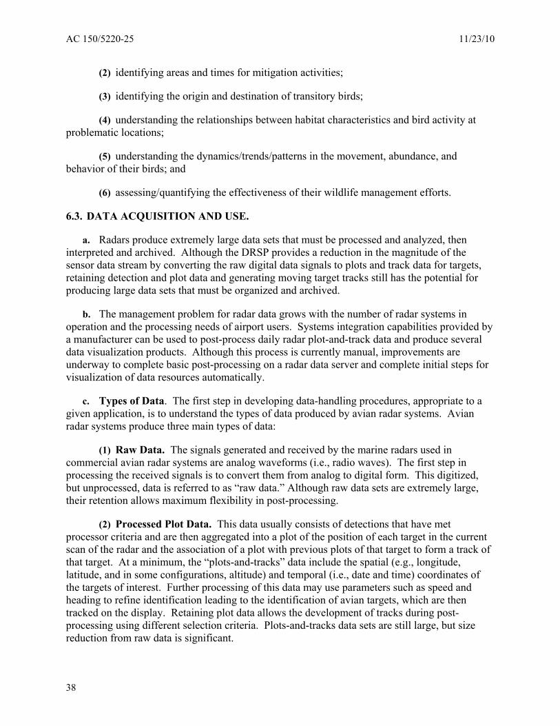
(3) Track Data. This data is most conveniently used when displayed in relation to geographic references. The analysis of individual tracks can lead to further refinement of target type and characteristics. The display of track data is the first product of the performance assessment. As figure 6-1 shows, tracks can be displayed for given time periods, such as hourly track summaries. Using track summaries, it is possible to identify daily timing and dynamics and to conduct analyses that relate bird activity to environmental conditions. Track data is also useful in identifying migratory events.
Figure 6-1. Example of an Hourly Track Summary
d. Data Processing. Avian radar data processing generally includes two steps. As described above, the first step produces digital data by sampling the analog data stream from the radar sensor and then processing the digitized data to remove clutter and detect and track targets. The second step takes the digitized data, which are now in a form that can be processed by a computer, to display the tracks over maps of the area on the computer screen. This step can be done by different commercially available software. In addition to raw data, processed data in the form of plots, tracks, and radar detection data should be archived in a form that allows ready retrieval and supports post-processing. The archival data can be used in post-processing that may use statistical, GIS, or other methods for data analysis. The general data processing process is illustrated in figure 6-2.
39
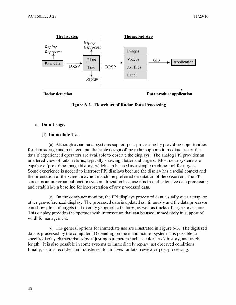
AC 150/5220-25 11/23/10
DRSP
Images
Videos
.txt files
Excel
Application
Radar detection Data product application
DRSP GIS
Raw data .Plots
.Trac
Replay Reprocess
Replay Reprocess
Replay
The fist step The second step
Figure 6-2. Flowchart of Radar Data Processing
e. Data Usage.
(1) Immediate Use.
(a) Although avian radar systems support post-processing by providing opportunities for data storage and management, the basic design of the radar supports immediate use of the data if experienced operators are available to observe the displays. The analog PPI provides an unaltered view of radar returns, typically showing clutter and targets. Most radar systems are capable of providing image history, which can be used as a simple tracking tool for targets. Some experience is needed to interpret PPI displays because the display has a radial context and the orientation of the screen may not match the preferred orientation of the observer. The PPI screen is an important adjunct to system utilization because it is free of extensive data processing and establishes a baseline for interpretation of any processed data.
(b) On the computer monitor, the PPI displays processed data, usually over a map, or other geo-referenced display. The processed data is updated continuously and the data processor can show plots of targets that overlay geographic features, as well as tracks of targets over time. This display provides the operator with information that can be used immediately in support of wildlife management.
(c) The general options for immediate use are illustrated in Figure 6-3. The digitized data is processed by the computer. Depending on the manufacturer system, it is possible to specify display characteristics by adjusting parameters such as color, track history, and track length. It is also possible in some systems to immediately replay just observed conditions. Finally, data is recorded and transferred to archives for later review or post-processing.
40
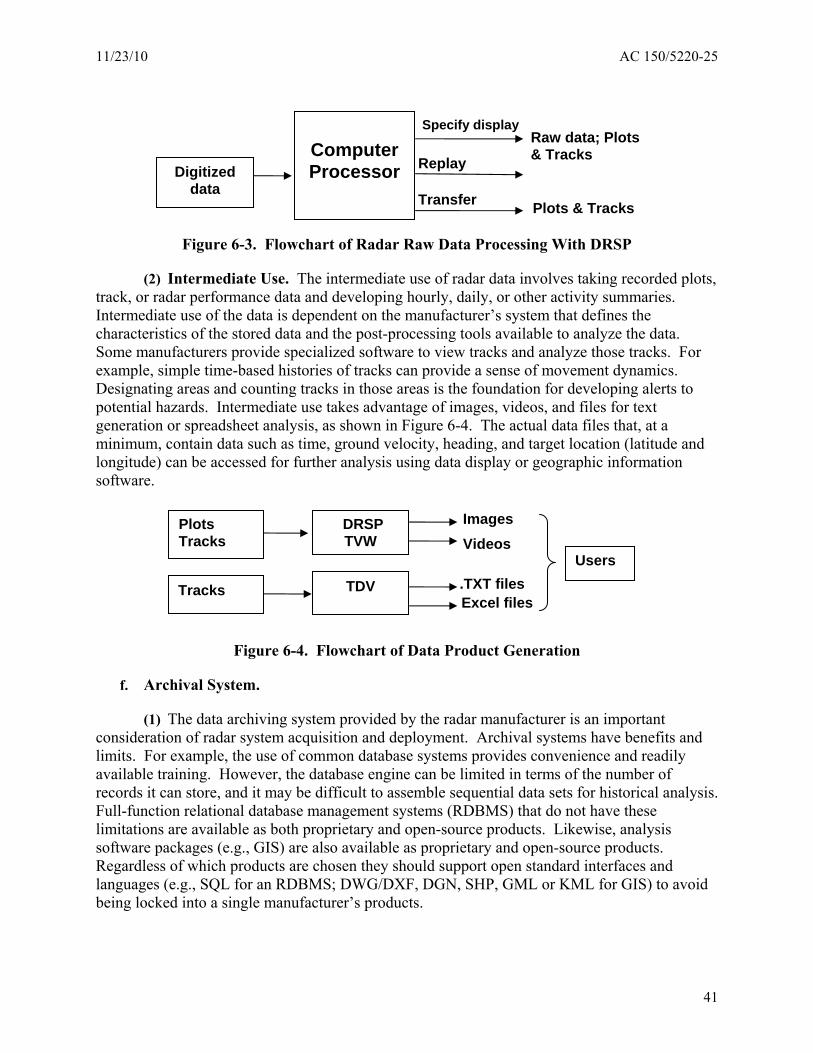
Specify display Raw data; Plots
Computer
Digitized data
& TracksProcessor Replay
Transfer Plots & Tracks
Figure 6-3. Flowchart of Radar Raw Data Processing With DRSP
(2) Intermediate Use. The intermediate use of radar data involves taking recorded plots, track, or radar performance data and developing hourly, daily, or other activity summaries. Intermediate use of the data is dependent on the manufacturer’s system that defines the characteristics of the stored data and the post-processing tools available to analyze the data. Some manufacturers provide specialized software to view tracks and analyze those tracks. For example, simple time-based histories of tracks can provide a sense of movement dynamics. Designating areas and counting tracks in those areas is the foundation for developing alerts to potential hazards. Intermediate use takes advantage of images, videos, and files for text generation or spreadsheet analysis, as shown in Figure 6-4. The actual data files that, at a minimum, contain data such as time, ground velocity, heading, and target location (latitude and longitude) can be accessed for further analysis using data display or geographic information software.
ImagesPlots DRSP Tracks TVW Videos
Users .TXT filesTracks TDVExcel files
Figure 6-4. Flowchart of Data Product Generation
11/23/10 AC 150/5220-25
f. Archival System.
(1) The data archiving system provided by the radar manufacturer is an important consideration of radar system acquisition and deployment. Archival systems have benefits and limits. For example, the use of common database systems provides convenience and readily available training. However, the database engine can be limited in terms of the number of records it can store, and it may be difficult to assemble sequential data sets for historical analysis. Full-function relational database management systems (RDBMS) that do not have these limitations are available as both proprietary and open-source products. Likewise, analysis software packages (e.g., GIS) are also available as proprietary and open-source products. Regardless of which products are chosen they should support open standard interfaces and languages (e.g., SQL for an RDBMS; DWG/DXF, DGN, SHP, GML or KML for GIS) to avoid being locked into a single manufacturer’s products.
41
AC 150/5220-25 11/23/10
(2) An important point to evaluate when considering avian radars is the efficiency with which the data is stored and the capabilities that exist for post-processing. To provide maximum utility, raw data storage is needed. Raw data may originate from the radar unit, but often have large file sizes that limit the length of time data can be recorded. This raw data is valuable because it provides a data set that can be reprocessed as part of a quality assurance program, assesses changes and improvements in the processing software, or enables the review of incidents of interest with full reprocessing capability. The raw data resource may also be an intermediate product of the digitization process. This data is often subject to compression algorithms, and it is possible to archive raw data for reprocessing for long time periods.
(3) Post-processing. The radar’s tracking capabilities enable a day’s worth of tracks to be visualized in different ways. Depending on the manufacturer solution, tracks may be stored as plot and track files or may be added to a database that contains additional data derived from the radar. Manufacturer solutions vary from a program that assembles and replays tracks from recorded data to external analytical engines, such as GIS programs, which assemble and process radar data.
(4) Reprocessing. Airport operators will find that there will be situations where it is important to reprocess data. Full reprocessing is only available if the raw data from the radar unit is recorded. This record is seldom available because of the massive size of the data sets generated by the radar. Alternatives exist in various approaches provided by different manufacturers. Raw data compression schemes reduce storage requirements, but storage of all radar data is still limited by size requirements. It is possible to develop storage systems that only retain data from a limited time and continuously roll over data sets. This approach would be suitable for event analysis. Reprocessing can also take a form in which a processed data set is used by a program that allows a review of plot-and-track data, such as using different criteria for track generation or the analysis of track density in relation to areas defined on a radar screen/area map overlay.
(5) Metadata.
(a) Metadata is data about data. It provides information that is not recorded with the primary measurement data, but which may be necessary to use and interpret the measurements. Metadata provides the context in which the measurements were made. For example, the track data output from an avian target (i.e., the primary measurement data) would typically include the spatial and temporal coordinates of the targets; it may not include the horizontal and vertical coordinates of the radar, the time zone of the date/time values (e.g., GMT versus local), the configuration of the radar (e.g., antenna type and angle, range setting), or how and when the radar was last calibrated. Depending on the avian radar system, some of this metadata may be recorded in a “configuration file” that is generated and used by the DRSP.
(b) Another common type of metadata is found in a data dictionary. A data dictionary is a human-readable document that names and describes the records and fields in the output data stream. A data dictionary provides details such as the type and length of each data element and the minimum and maximum values of numeric fields. If the output data is simply streamed into ASCII “flat” files, a single data dictionary may suffice. However, if the data is streamed into an RDBMS, a second data dictionary is also required that describes the tables,
42
11/23/10 AC 150/5220-25
records, and fields in the database; the type and length of data elements; minimum and maximum values; and similar information. A document that maps the elements in the output data stream into the tables and elements of the database is also desirable.
(c) The importance of metadata, including a data dictionary, cannot be overemphasized. Without it, the avian radar becomes, in a sense, a black-box that limits the users’ ability to understand and interpret the data and to use the data for other, perhaps unforeseen, applications. As an example, avian radars can only directly measure the range and azimuth of a target. If the DRSP computes the altitude of a target, the description of the altitude field in the data dictionary should detail how (including the formula) altitude is computed, the assumptions that go into that computation (e.g., a narrow-beam dish antenna was used), whether the altitude values are reported as integer or decimal numbers, the precision of the computed altitudes as a function of range (e.g., ±4 m at 1 km), and the units and datum in which the altitude values are recorded (e.g., meters above radar level). From this information and other metadata, the users can, for example, compute the height of a target above ground level.
(d) Metadata needs to be tightly coupled with the primary measurement data. Both the data and metadata should be contained in the same data storage mechanism. When users retrieve measurement data, they should be able to easily find the accompanying metadata, and vice versa. Equally important, when the measurements data are moved from one RDBMS to another, the metadata should be moved.
6.4. DATA ANALYSIS AND THE RISK ASSESSMENT PROCESS.
a. Once avian radar data can be reliably obtained and used, the process of analyzing the data can begin. The data allows for a risk assessment to be performed and enables an airport to determine where potential bird threats exist on the airport.
6.5. CONTINUOUS PROGRAM IMPROVEMENT.
a. Safety performance monitoring validates the WHMP, confirming the organization’s safety objectives. Through regular review and evaluation, management can pursue continuous improvements in wildlife management and may revise safety objectives, policies, procedures, and training programs to ensure that the WHMP remains effective and relevant to the organization’s operation.
b. The wildlife manager, in assessing the effectiveness of the WHMP, should work with the persons that have direct responsibility for analyzing hazards, identifying control measures derived from that analysis, and ensuring those measures are effective.
43

AC 150/5220-25 11/23/10
This page intentionally left blank.
44
11/23/10 AC 150/5220-25 Appendix A
APPENDIX A. ADDITIONAL SYSTEM STANDARDS.
a. Design Standards.
(1) Total Life. Avian radar systems must be designed to perform its intended function for its “total life” period when maintained according to the manufacturer’s instructions. The “total life” for which the equipment is designed, assuming it is used and maintained in accordance with the manufacturer’s recommendations, must be a minimum of 10 years.
(a) Avian radar equipment reliability. The mean time between failure for the avian radar system must be at least 4000 hours of transit time.
(2) Environment. Avian radar systems, including all associated outdoor mounted equipment, must be designed to withstand the following extreme climatic conditions and operate without damage or failure:
(a) Weather:
(i) Ambient temperature range: -25 degrees F (-32 degrees C) to +123 degrees F (+52 degrees C) ambient outdoor air temperature (may be modified by the purchaser if the device is to be used in extreme climates).
(ii) Relative Humidity: 5% to 90% (may be modified by the purchaser if the device is to be used in extreme climates).
(iii) General Environment: Dust and airborne hydrocarbons resulting from jet fuel fumes.
(b) Components must be protected from mechanical, electrical, and corrosion damage causing impairment of operation due to rain, snow, ice, sand, grit, and deicing fluids.
(c) All electric motors, controls, and electrical wiring / equipment placed outdoors must be weatherproof in order to protect the equipment and connections from the elements.
(d) All non-moving structural components and materials must be individually and collectively designed and selected to serve the total life requirement under such conditions. Moving or working components, such as tires, motors, brakes, etc. are exempt from this provision.
(3) Power Supply. In the event of a power failure, the system must have the capability to automatically power-up and operate in the condition and settings that were available just prior to the power failure.
45
AC 150/5220-25 11/23/10 Appendix A
b. Construction Standards.
(1) General Requirements:
(a) All equipment and material must be new, undamaged, and of the best grade; decisions concerning quality, fitness of materials, or workmanship are determined by the purchaser.
(b) Where items exceed one in number, the manufacturer must provide products from the same component manufacturer with identical construction, model numbers, and appearance.
(c) Insofar as possible, products must be the standard and proven design of the manufacturer.
(d) The manufacturer must install electrical connections for power, controls, and devices in accordance with NEMA and NEC recommendations and requirements. Transmitting equipment must be installed and adjusted in accordance with manufacturer's published instructions and the requirements specified herein.
(2) Workmanship. The manufacturer must install all equipment, materials, specialties, etc., in accordance with the best engineering practice and standards for this type of work.
(3) Materials:
(a) Equipment exposed to the weather must be weatherproof type.
(b) All external components must be constructed and finished in a manner to inhibit corrosion based on the purchaser’s specific environment.
(c) All machined surfaces must be coated with a suitable rust preventative.
(4) Parts:
(a) Standard and Commercial Parts. Insofar as practicable, commercially available standard parts complying with commercial and/or military standards must be used throughout.
(b) Interchangeability and Replaceability.
(i) All parts having the same manufacturer’s part number must be directly and completely interchangeable with each other with respect to installation and performance.
(ii) All components and assemblies incorporated in the equipment must be designed and manufactured to dimensional tolerances which permit future interchangeability and facilitate the replacement of parts.
(c) Spare / Replacement of Parts. The manufacturer must develop and provide to the purchaser a parts list, including associated replacement/repair costs.
46
11/23/10 AC 150/5220-25 Appendix A
(d) Substitutions. The purchaser must approve any material or equipment designated as an “or equal” product, but these items must be clearly distinguished and noted in the technical manuals as substitutions.
(5) Codes, Standards, Regulations, and References. The manufacturer must recognize and comply with all codes and standards applicable to the design and construction of this type of equipment which are generally accepted and used as good practice in the industry.
c. Installation and Acceptance Standards.
(1) Installation:
(a) Obstructions and other standards. Avian radar systems must conform to applicable airport obstruction criteria, marking and lighting, and equipment design and installation standards.
(b) Prior to installation, the manufacturer must obtain all site construction, environmental, and coordination requirements for installation of the detection system at the airport.
(c) Unless otherwise specified by the purchaser, installers of mechanical and electrical work must participate in any pre-installation meetings at the project site to review conditions of other related project work.
(d) The manufacturer must provide trained personnel at the time of delivery to place the device into operation.
(e) Equipment located outside of paved surfaces should be designed and built with ease of maintenance in mind.
(2) Quality Assurance. The manufacturer must test all of the equipment installed under this specification and demonstrate its proper operation to the purchaser. The manufacturer must furnish all required labor, testing, instruments and devices required for the conduct of such tests.
(a) The manufacturer must install all electrical, instrumentation, and mechanical works to the satisfaction of the purchaser, with inspecting authorities having jurisdiction.
(b) The manufacturer must notify the purchaser in writing of any instances in the specifications that are in conflict with applicable codes. The manufacturer must perform all work in accordance with applicable laws, rules, or regulations.
(c) Deviations from the specifications required for conformance with the applicable codes and/or laws must be corrected immediately, but not until such deviations have been brought to the attention of the purchaser.
(d) For applicable codes and/or laws that govern the minimum design requirements: where this AC calls for materials, vents, sizes, design details, etc., in excess of the code requirements, the AC takes precedence.
47
AC 150/5220-25 11/23/10 Appendix A
(3) Inspection. The manufacturer will establish a formalized final inspection regimen to ensure each system is adjusted as designed, all systems are operating properly, and the finish in complete and undamaged. The user may choose to participate in the final inspection of designated systems.
(4) Testing. After the equipment has been installed and the various units have been inspected, adjusted/calibrated, and placed in correct operating condition, the equipment must be field tested in accordance with the purchaser’s testing procedures and requirements. The field tests must demonstrate that the equipment functions are in compliance with the specifications over the entire range of operation. The manufacturer must report any unusual conditions and correct deficiencies of any of the units.
(a) Preliminary Qualification Tests. Preliminary qualification tests may be specified by the purchaser.
(b) Formal Qualification Tests. Formal qualification tests may be specified by the purchaser.
(5) Manuals and Publications. The following operation and maintenance manuals must accompany the delivered equipment. The quantity of items is specified by the purchaser. No special format is required.
(a) Operator’s handbook.
(b) Illustrated parts breakdown and list.
(c) Preventive maintenance schedule.
d. Equipment Training and Maintenance Standards.
(1) Training:
(a) The manufacturer must provide trained personnel at the time of delivery to adequately train airport/airline staff in the operation and maintenance of the detection equipment.
(b) Training must include written operating instructions that depict the step by step operational use of the detection system. Written instructions must include, or be supplemented by, materials which can be used to train subsequent new operators.
(c) Training topics must include trouble shooting and problem solving, in the form of theory and hands-on training, for personnel designated by the purchaser.
(d) At least four hours of training for airport/airline personnel must be provided by the manufacturer. Training selected personnel as part of a “Train the Trainer” program will also satisfy this requirement.
(e) Upon the completion of training, the manufacturer must issue to each participant a certificate of competency.
48
11/23/10 AC 150/5220-25 Appendix A
(2) Maintenance:
(a) Preventive. The manufacturer must develop and provide to the purchaser written documentation on recommended preventive maintenance actions.
(b) Cleaning. The manufacturer must develop and provide to the purchaser written documentation on recommended cleaning procedures, including solvent types and tools.
(c) Inspection. The manufacturer must develop and provide to the purchaser written documentation on regularly scheduled maintenance inspection procedures. A focus on sensitive equipment and schedule timelines must be included in the documentation.
(d) Recalibration. The manufacturer must develop and provide to the purchaser a recalibration plan and recalibration procedures. Recalibration should ensure wildlife management program performance specifications are maintained for the life of the sensor.
49

AC 150/5220-25 11/23/10 Appendix A
This page intentionally left blank.
50