Embed Size (px)
Citation preview
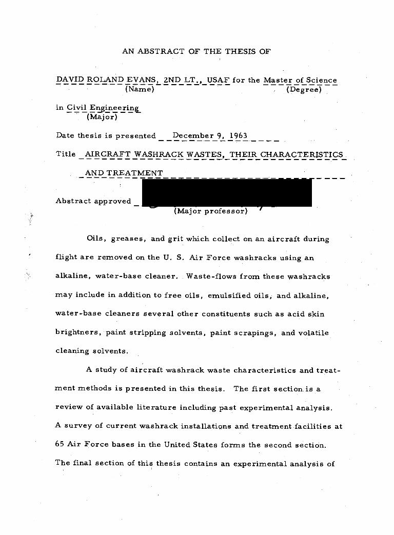
AN ABSTRACT OF THE THESIS OF
DAVID ROLAND EVANSL 2ND LT., USAF for the Master of Science (Name) (Degree)
in Civil Engineering_ (Major)
Date thesis is presented December 9, 1963
Title AIRCRAFT WASHRACK WASTES, THEIR CHARACTERISTICS
AND TREATMENT
Abstract approved Major professor)
Oils, greases, and grit which collect on an aircraft during
flight are removed on the U. S. Air Force washracks using an
alkaline, water -base cleaner. Waste -flows from these washracks
may include in addition to free oils, emulsified oils, and alkaline,
water -base cleaners several other constituents such as acid skin
brightners, paint stripping solvents, paint scrapings, and volatile
cleaning solvents.
A study of aircraft washrack waste characteristics and treat-
ment methods is presented in this thesis. The first section is a
review of available literature including past experimental analysis.
A survey of current washrack installations and treatment facilities at
65 Air Force bases in the United States forms the second section.
The final section of this thesis contains an experimental analysis of
--
the washrack wastes and the treatment facility at Portland AFB,
Oregon.
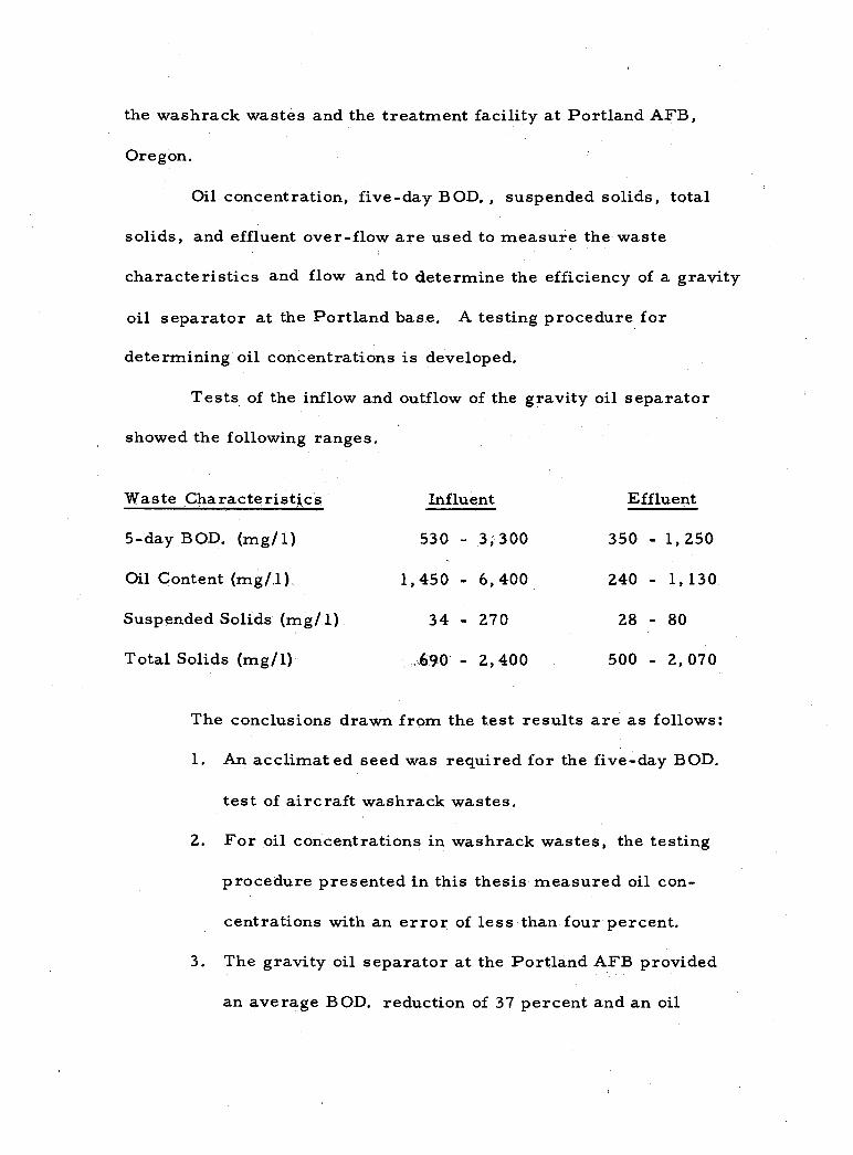
Oil concentration, five -day BOD. , suspended solids, total
solids, and effluent over -flow are used to measure the waste
characteristics and flow and to determine the efficiency of a gravity
oil separator at the Portland base. A testing procedure for
determining oil concentrations is developed.
Tests of the inflow and outflow of the gravity oil separator
showed the following ranges.
Waste Characteristics Influent Effluent
5 -day BOD. (mg /1) 530 - 3,300 350 - 1,250
Oil Content (mg /,1), 1,450 - 6,400 240 - 1,130
Suspended Solids (mg/ 1) 34 - 270 28 - 80
Total Solids (mg /1) ,:.690 - 2, 400 500 - 2, 070
The conclusions drawn from the test results are as follows:
1. An acclimated seed was required for the five -day BOD.
test of aircraft washrack wastes.
2. For oil concentrations in washrack wastes, the testing
procedure presented in this thesis measured oil con-
centrations with an error of less than four percent.
3. The gravity oil separator at the Portland AFB provided
an average BOD. reduction of 37 percent and an oil
removal of 70 percent.
4. The effluent from the gravity oil separator contained
only emulsified oils.
5. The average oil content of the treated effluent was 589
ppm. This value greatly exceeded the general limit of
30 ppm, established by states which had oil concentration
standards.
6. An average of 410 gallons of water was required to wash
a C -119 aircraft at Portland AFB.
AIRCRAFT WASHRACK WASTES, THEIR CHARACTERISTICS AND TREATMENT
by
DAVID ROLAND EVANS SECOND LIEUTENANT, UNITED STATES AIR FORCE
A THESIS
submitted to
OREGON STATE UNIVERSITY
in partial fulfillment of the requirements for the
degree of
MASTER OF SCIENCE
June 1964
APPROVED:
Associate Professor of Civil Engineering
In Charge of Major
Head of Department of Civil Engineering
Dean of Graduate School
Date thesis is presented December 9, 1963
Typed by Nancy Kerley
1vil
ACKNOWLEDGMENTS
A thesis represents the work and co- operation of many
people and organizations. To this end, the author wishes to express
a sincere thank you:
To the Air Force Institute of Technology, Wright -Patterson
AFB, Ohio, for accepting me into their advanced educational program
under full scholarship and salary. Without their help an advanced
degree would not have been possible.
To the Civil Engineering faculty at Oregon State University
and in particular to Professor Donald C. Phillips, for his untiring
and patient counsel.
To the engineering personnel at Air Force bases across the
United States for providing the information describing current
policies and treatment methods for aircraft washrack wastes.
To the airmen of the 939th Troop Carrier. Squadron,
Portland AFB, and the Adair AFS Motor Pool for their interest and
support.
To SSgt. Vail, 939th T. C. Squadron, for his help in taking
samples; Major Ream and Don Hill, Portland base engineering office
for their very important help in getting the thesis research underway.
And above all to my wife Carol for her love and understanding.
TABLE OF CONTENTS
INTRODUCTION
Purpose of the Study Statement of Scope
LITERATURE REVIEW
Composition and Quantity of Washrack Wastes Treatment of Washrack and Related Wastes
SURVEY OF CURRENT WASHRACK INSTALLATIONS AND TREATMENT FACILITIES AT AIR FORCE BASES IN THE UNITED STATES
Aircraft Washrack Wastes Questionnaire Miscellaneous Air Force Policies
ANALYSIS OF WASHRACK WASTES AND THE TREATMENT FACILITY AT PORTLAND AFB, OREGON
Page
3
5
24
24 27
29
Introduction 29 Method of Study and Experimental Design 32 Analytical Methods 33 Experimental Procedure 37 Experimental Results 39 Conclusions 43 Recommendations for Further Studies 44
BIBLIOGRAPHY 45
APPENDIX A 48
Summary of Military Specifications for Cleaning Compounds 48
Aircraft Surface, Alkaline Waterbase 48 Metal Conditioner and Brightner 48 Source for Military Specifications 49
Chemical Composition of Aircraft Cleaners 49
1
3
5
9
TABLE OF CONTENTS (continued)
Page
Control Specification for a Commercial Cleaner, LIX 3852 50
Other Cleaning Compounds Sometimes Present in Washrack Wastes 51
APPENDIX B
Experimental Testing Procedures
Biochemical Oxygen Demand Oil and Grease
APPENDIX C
52
52
52 54
60
Aircraft Washrack Wastes Questionnaire 60 Corrections to Aircraft Washrack Waste Questionnaire 63 Results of Chemical Test Performed by the Air Force
on Washrack Wastes 64 Descriptions of Washrack Waste Treatment Facilites
at U. S. Air Force Bases 69
-
LIST OF FIGURES
Figure
Chemical coagulation plant, Wiesbaden Air Base,
Page
1
Germany. 19
2 Air flotation plant diagram. 21
3 Gravity oil separator, Portland AFB. 31
4 Evaporation curve. 58
5 Industrial Waste Treatment Plant No. 1, McClellan AFB. 74
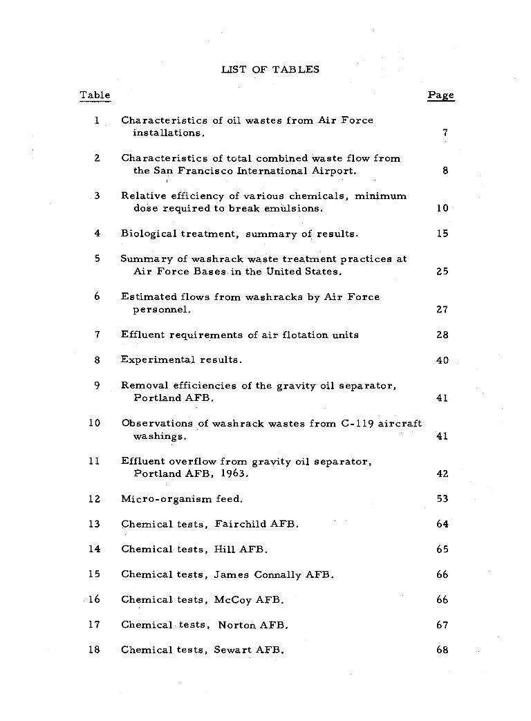
LIST OF TABLES
Table
1 Characteristics of oil wastes from Air Force installations.
Characteristics of total combined waste flow from the San Francisco International Airport.
3 Relative efficiency of various chemicals, minimum dose required to break emulsions.
4 Biological treatment, summary of results.
Summary of washrack waste treatment practices at Air Force Bases in the United States. 25
Estimated flows from washracks by Air Force personnel. 27
7 Effluent requirements of air flotation units 28
8 Experimental results. 40
Removal efficiencies of the gravity oil separator, Portland AFB. 41
10 Observations of washrack wastes from C -119 aircraft washings. 41
11 Effluent overflow from gravity oil separator, Portland AFB, 1963.
Page
7
10
15
12 Micro -organism feed.
42
53
13 Chemical tests, Fairchild AFB. 64
14 Chemical tests, Hill AFB. 65
15 Chemical tests, James Connally AFB. 66
16 Chemical tests, McCoy AFB. 66
17 Chemical tests, Norton AFB. 67
18 Chemical tests, Sewart AFB. 68
2 8
5
6
9
AIRCRAFT WASHRACK WASTES, THEIR CHARACTERISTICS AND TREATMENT
INTRODUCTION
Aircraft of the United States Air Force log countless air
miles each year. Some of these aircraft are on routine training
missions, some are on patrol flights, while other aircraft are
transporting men and support materials. From these flights, oils,
greases, dirt, and metal oxides collect on the aircraft surfaces. To
remove these films the aircraft are washed at periodic intervals or
when other maintenance operations are to be performed.
The aircraft washing procedure involves the spraying of
specified cleaners on prescribed skin surfaces to loosen and
emulsify the collected films. The surfaces are then brushed and
rinsed off with hot or cold water. If need be, the procedure is
repeated. Following the aircraft washing, the clad aluminum sur-
faces may be sprayed with an acid skin brightner designed to remove
corrosion products and to improve the appearance of the aircraft.
The brightner is applied with a nonatomizing spray, allowed to sit
for five to twelve minutes, and then is rinsed off with water (7).
The wastes normally derived from the washracks are com-
posed of free -floating oils and greases, settleable solids, and a
milky, soap -like emulsion containing suspended oil and grease
particles. The milky emulsion is extremely stable and resistant to
many methods of cracking. Investigators have observed that the
"untreated emulsions would stand for months without any
tendency to separate, retaining their milk -like appearance" (16,
p. 436). Excluding free - floating oils, the oil concentration in the
emulsion may vary from several ppm. to several thousand ppm. with
most of the oil concentrations falling into the 100 to 1, 000 ppm. range.
The discharge of untreated washrack wastes which can be
(1) high in biochemical oxygen demand (BOIL), (2) toxic to stream
life, and may (3) reduce surface re- aeration, (4) cause taste and
odor problems in drinking water supplies, and (5) cause offensive
and unsightly conditions along stream banks may, but not necessarily,
create pollution problems.
Air Force Regulation 91 -9 states,
Military authorities in the continental U. S. will co- operate with civil authorities in preventing the pollution of surface or underground waters by sewage or industrial wastes from Air Force installations by com- pliance with the laws of the state where the installation is located.
In the states where oil concentration limits exist, the acceptable
limit of oil concentration in streams varies from 15 to 30 ppm. (22,
p. 163).
Industrial wastes at U. S. Air Force installations arise
chiefly from metal plating, aircraft and vehicle washing, and engine
z
...
3
part cleanings.
The extensive industrial activity carried on at Air Material Command installations results in more varied and complex wastes, but almost all installations generate wastes from aircraft washings and small plating operations (22, p. 162).
Thus not only aircraft washrack waste, but acids, alkalies,
chromates, and heavy oils may in some cases be added to the treat-
ment considerations.
Purpose of the Study
The purpose of this study is to develop a comprehensive
picture of the past, present, and future problems and solutions con-
nected with the examination and treatment of aircraft washrack
wastes.
Statement of Scope
The body of this thesis is divided into three main sections.
The first section traces the experimentation and development of
methods to treat washrack wastes. A survey of current washrack
installations and treatment facilities at 65 Air Force bases in the
United States is presented in the second section. The third section is
concerned with the development of experimental procedures to
evaluate washrack wastes and treatment methods, These procedures
are then applied to the analysis of washrack wastes and treatment
facilities at Portland AFB, Oregon.
4
LITERATURE REVIEW
One method of studying an industrial waste problem is to
investigate (1) the characteristics and quantity of the waste, (2)
treatment theories on laboratory scale, and (3) to apply knowledge
gained from laboratory studies to full scale operations.
The available literature on washrack wastes and methods of
treatment have been arranged in this manner. Other related wastes
sometimes combined with washrack wastes, such as wastes from
metal plating and engine part cleaning, will be included when
applicable in the discussion.
Composition and Quantity of Washrack Wastes
Cleaners. The Air Force specifications for cleaners are
written on a performance basis. For this reason a number of dif-
ferent commercial cleaners are used (Appendix A).
Generally the cleaners are alkaline, water -base compounds
made up of the following constituents: aromatic hydrocarbons or
trisodium phosphate, an alkaline pH buffer such as caustic potash,
emulsifying agents and glycol derivatives. "The emulsifying agents
are nonionic detergents which are biologically degradable, and fatty
acids which combine with caustic potash to form a potassium soap.
5
6
The glycols serve as couplers."
An acid skin -brightner, sometimes used in conjunction with
the alkaline, water -base cleaner to remove stains' from clad
aluminum surfaces, conforms to military specification MIL -C- 25378.
Prior to about 1958, a commercially manufactured crude
soap (often referred to as gunk) mixed with kerosene was used in
place of the alkaline, water -base cleaner for washing aircraft, De-
pending on the strength required for aircraft cleaning, the ratio of
gunk to kerosene usually varied between 1:7 and :1:10 (14, p. 284).
Composition of Wastes. Free and emulsified oils, and
greases are found in the industrial wastes of most Air Force instal-
lations. Emulsified oils and greases are defined by the Air Force
(24, Appendix p, 1) as "the type of waste resulting from the cleaning
of engines, gears, and similar parts of machinery with gunk and
kerosene or other solvents of grease and oil, " Waste containing only
free -floating oils and greases are referred to by the Air Force as
"a waste resulting from the washing of aircraft using an alkaline,
water -base washing compound as specified in MIL -C- 25769. This
waste does not contain emulsified oil or grease in significant
quantity, 2
1For reference to quote see foot note 4, page 49.
2The reader is urged to study page 43 of this thesis in conjunc- tion with this definition.
1
7
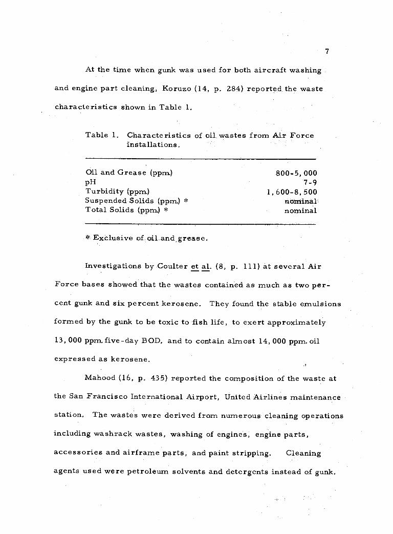
At the time when gunk was used for both aircraft washing
and engine part cleaning, Koruzo (14, p. 284) reported the waste
characteristics shown in Table 1.
Table 1. Characteristics of oil. wastes from Air Force installations.
Oil and Grease (ppm) 800 -5, 000 pH 7 -9 Turbidity (ppm.) 1,600-8,500 Suspended Solids (ppm.) nominal Total Solids (ppm.) * nominal
*.Exclusive of Dil_and,grease.
Investigations by Coulter et al. (8, p. 111) at several Air
Force bases showed that the wastes contained as much as two per-
cent gunk and six percent kerosene. They found the stable emulsions
formed by the gunk to be toxic to fish life, to exert approximately
13, 000 ppm. five -day BOD. and to contain almost 14, 000 ppm. oil
expressed as kerosene.
Mahood (16, p. 43 5) reported the composition of the waste at
the San Francisco International Airport, United Airlines maintenance
station. The wastes were derived from numerous cleaning operations
including washrack wastes, washing of engines, engine parts,
accessories and airframe parts, and paint stripping. Cleaning
agents used were petroleum solvents and detergents instead of gunk.
e
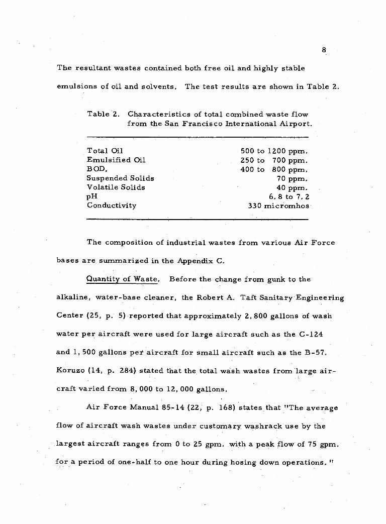
The resultant wastes contained both free oil and highly stable
emulsions of oil and solvents. The test results are shown in Table 2.
Table 2. Characteristics of total combined waste flow from the San Francisco International Airport.
Total Oil 500 to 1200 ppm. Emulsified Oil 250 to 700 ppm. B OD. 400 to 800 ppm. Suspended Solids 70 ppm. Volatile Solids 40 ppm. pH 6. 8 to 7. 2 Conductivity 330 micromhos
The composition of industrial wastes from various Air Force
bases are summarized in the Appendix C.
Quantity of Waste. Before the change from gunk to the
alkaline, water -base cleaner, the Robert A. Taft Sanitary Engineering
Center (25, p. 5) reported that approximately 2, 800 gallons of wash
water per aircraft were used for large aircraft such as the C -124
and 1,500 gallons per aircraft for small aircraft such as the B -57.
Koruzo (14, p. 284) stated that the total wash wastes from large air-
craft varied from 8, 000 to 12,000 gallons.
Air Force Manual 85 -14 (22, p. 168) states that "The average
flow of aircraft wash wastes under customary washrack use by the
largest aircraft ranges from 0 to 25 gpm. with a peak flow of 75 gpm.
for a period of one -half to one hour during hosing down operations. "
8
9
McClellan AFB, 3 estimates the combined flow from their two wash -
racks to be 13, 000 gpd.
Treatment of Washrack and Related Wastes
Investigators have generally followed the pattern of first
determining methods of cracking the oil- water -solvent emulsions
to facilitate gravity separation. After cracking the emulsion, ways
to treat the partially clarified liquid using chemical, biological, or
physical means were studied.
Experimental Investigations. The experimental work re-
ported in the literature was done prior to the adoption of the alkaline,
water -base cleaner. However, because the gunk- kerosene cleaner
is still used to clean engine parts and because future experiments
will follow many of the same procedures this topic has been included.
The wastes under discussion in this section are assumed to contain
the gunk- kerosene cleaner unless otherwise specifically stated.
Studies of washrack waste samples by the R. A. Taft
Engineering Center (25) showed that after free oils had been sep-
arated, the remaining emulsified oils after several months did not
exhibit any tendency to separate.
3The information was taken from the letter written by Base Engineering Office, McClellan AFB, Càlifornia.
10
For complete treatment the R. A. Taft Engineering Center
and others found it necessary to use chemicals to break the
emulsions. J. B. Coulter, et al. (8, p. 100) states,
A review of specifications and an approximate analysis indicate that various soaps and soap -like compounds make up a large fraction of the gunk. Therefore, it might be expected to react with mineral acids or hardness ions to form the typical insoluble curd common to household soaps.
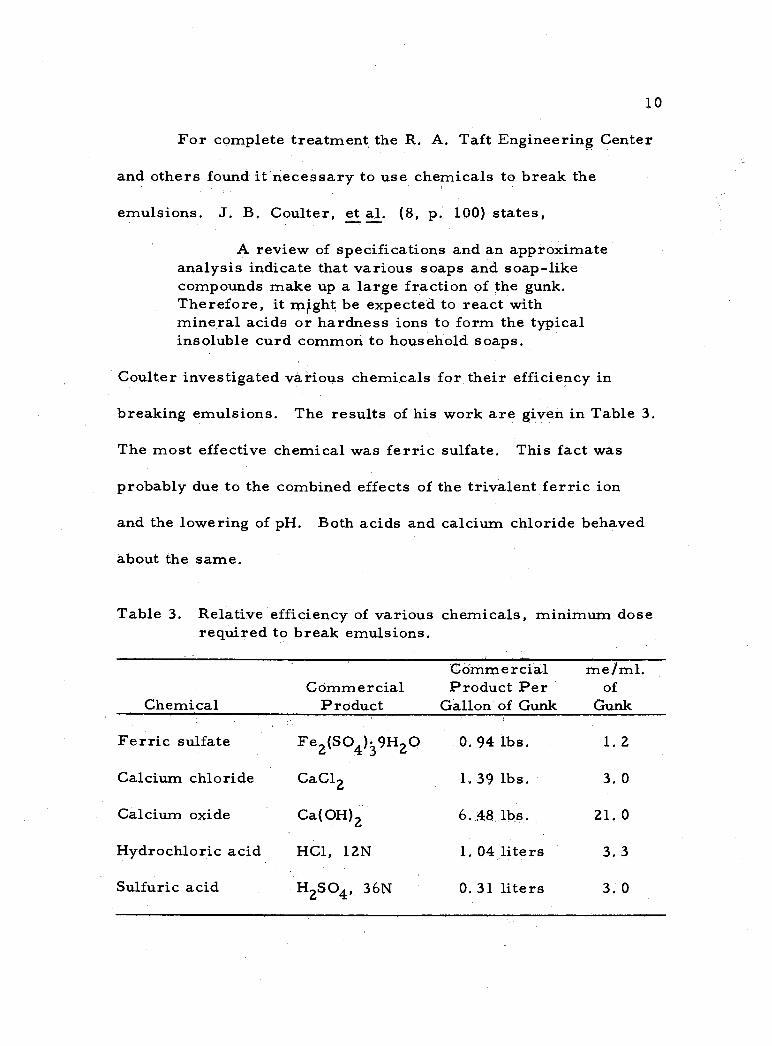
Coulter investigated various chemicals for their efficiency in
breaking emulsions. The results of his work are given in Table 3.
The most effective chemical was ferric sulfate. This fact was
probably due to the combined effects of the trivalent ferric ion
and the lowering of pH. Both acids and calcium chloride behaved
about the same.
Table 3. Relative efficiency of various chemicals, minimum dose required to break emulsions.
Chemical Commercial
Product
Commercial Product Per
Gallon of Gunk
me/ml. of
Gunk
Ferric sulfate Fe2(SO4)39H2O 0. 94 lbs. 1.2
Calcium chloride. CaCl2 1.39 lbs. 3. 0
Calcium oxide Ca(OH)2 6.48. lbs. 21,0
Hydrochloric acid HG1, 12N 1. 04 liters 3.3
Sulfuric acid H2SO4, 36N 0. 31 liters 3. 0
11
The Water Pollution Research Board of England (12, p. 71)
found that at least 4000 ppm. each of aluminum sulfate and sulfuric
acid were required to break the emulsion. Sulfuric acid and common
salts by themselves also produced satisfactory results. They also
reported that unless the pH was reduced to 2. 6, aluminum, ferric
or calcium salts produced very bulky precipitates.
Jar tests by Coulter's group (8, p. 102) showed that the floc
characteristics of both ferric sulfate and alum were pH dependent.
Floc first formed at pH 5. 0 - 4. 7; poor floc was observed at pH 4. 7-
4. 0; good results again were recorded at pH 4. 0 and below.
The R. A. Taft Engineering Center (25, p. 2) came to the
conclusion that calcium chloride had a number of "practical ad-
vantages" over ferric sulfate or alum.
It is low in cost, easy to handle, readily soluble in the waste, requires only a flash mix, and produces a low volume of sludge even with excess doses. More- over, optimum results are not pH dependent.
In the case of ferric sulfate, the Taft Center pointed out that
the addition of alkalinity such as lime to the ferric sulfate produced
a stronger floc over a wider range of chemical application with
faster and better clarification. In one instance the net effect was
to raise the pH from 2. 8 to 5. 7 and the light transmittance from ten
percent to 75 percent.
After methods to break the emulsion were studied, the second
12
step was to determine on a laboratory scale the best method to achieve
a neutral, oil -free effluent. Investigations were conducted using
filtration, lagooning, air flotation, and biological treatment.
Coulter et al. (8, p. 108) in their summary of the R. A. Taft
Engineering Center report (25) stated that, when a previously
cracked emulsion free of floating material was passed through filter
paper, an effluent of tap water clarity was produced.
To explore the possibility of using filters in plant operation,
small tubes of sand excelsior, wood chips, glass wool, hay, activated
carbon, and sawdust were tried as filter media. The test procedure
followed was (1) emulsion cracking using an acid or calcium chloride
in a flash mix, (2) 30 minute separation period, (3) removal of
floating oil and scum, and (4) filtration of the subnatant.
The group found that sawdust produced the best effluent.
Further tests were made using three inch diameter tubes filled with
sawdust to a depth of 12 inches and packed to a density of approxi-
mately 13 pounds per cubic foot. Both untreated waste and cracked
subnatant were filtered through the sawdust under a free head of two
inches. Very poor results were obtained with the untreated waste.
With pretreated wastes, at pH 7, the filtrate developed a yellow -
green tinge and a slight turbidity in filter runs using both cracking
agents. A faint odor characteristic of sawdust could be detected.
;.
13
Color and odor were undetectable at á dilution of three parts tap
water to one part filtrate. Studies showed that the residual oil in
approximately 1, 100 gallons of pretreated washrack waste could be
removed with a cubic foot of sawdust.
The R. A. Taft Engineering Center (25, p. 20) reported
that sawdust filtration reduced the toxicity to fat -head minnows by
a factor of 10.
Coulter et al, (8, p. 102), and the R. A. Taft Engineering
Center (25, p. 2) reported the effects of prolonged settling or
lagooning. Untreated waste showed no clarification after several
months, but pretreated wastes gradually cleared. Samples of the
subnatant from the pretreated waste were taken after 30 minutes
and 24 hours separation. After 30 minutes the BOD. was 1,800
ppm. and after 24 hours it was 500 ppm. The oil content was 1,000
ppm. at 30 minutes and 85 ppm. at 24 hours.
Dissolved air flotation was investigated by the R. A. Taft
Engineering Center (25, p. 37) and reviewed by Coulter et al. (8,
p. 103). To duplicate the air flotation process on a laboratory scale,
a cylinder similar to that described by Rohlich (17, p. 304) was.
used. Using coagulants such as ferric sulfate, 90 percent of the
cylinder volume was clarified nearly three times faster by the
flotation process than by simple gravity separation. At the end of
14
two hours the oil content of the subnatant was thé same for the two
cases.
Pilot plant studies were conducted at Carswell Air Force
Base, Texas, to evaluate dissolved air flotation equipment. A
"Sediflotor" air flotation unit was operated at a flow rate of 90 gpm. ,
and at an air saturation tank pressure of 40 psi. gauge. Both ferric
sulfate and alum were used as emulsion cracking agents (25, p. 39).
Samples taken from a receiving stream at a point several hundred
yards below the outfall showed oil contents less than 20 ppm. as
measured by the direct extraction method (15, p. 1840). Alum and
ferric sulfate produced the same oil removal; however, the rust
colored floc of ferric sulfate in the effluent caused unsightly
conditions along the stream banks.
Tests were also conducted by the R. A. Taft Engineering
Center to determine the effect of untreated and pretreated aircraft
washrack wastes on trickling filters being fed primarily with
domestic sewage. An apparatus resembling that described by
Gloyna (10, p. 1356) was used. The device consisted of three, 24
inch long plastic tubes three inches in diameter and mounted on a 2. 5
percent slope. The tubes were rotated slowly while wastes pumped in
at the upper end trickled slowly over a growth that developed on the
inner walls of the tubes. A summary of results presented by
15
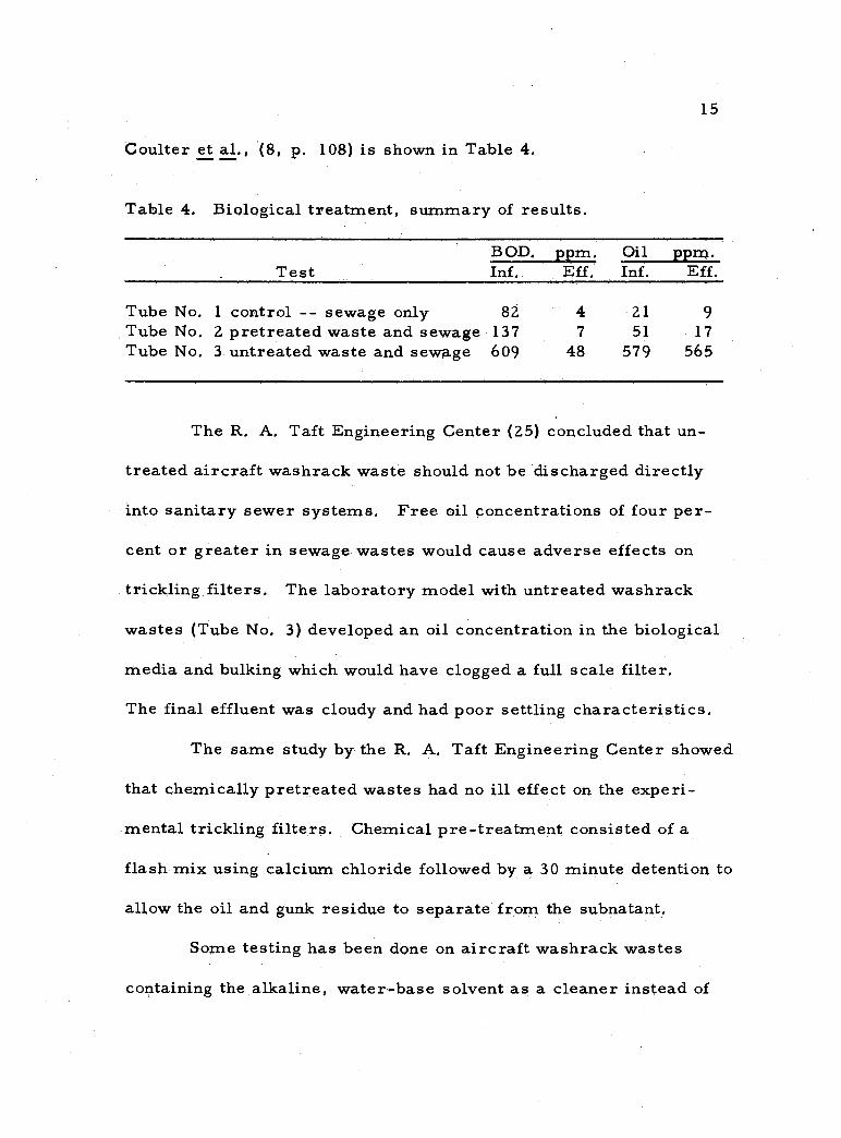
Coulter et al., (8, p. 108) is shown in Table 4.
Table 4. Biological treatment, summary of results.
BOD. ppm. Oil ppm. Test Inf. Eff. Inf. Eff.
Tube No. 1 control -- sewage only 82 4 21 9 Tube No. 2 pretreated waste and sewage 137 7 51 17 Tube No. 3 untreated waste and sewage 609 48 579 565
The R. A. Taft Engineering Center (25) concluded that un-
treated aircraft washrack waste should not be discharged directly
into sanitary sewer systems. Free oil concentrations of four per-
cent or greater in sewage wastes would cause adverse effects on
trickling filters. The laboratory model with untreated washrack
wastes (Tube No. 3) developed an oil concentration in the biological
media and bulking which would have clogged a full scale filter.
The final effluent was cloudy and had poor settling characteristics.
The same study by the R. A. Taft Engineering Center showed
that chemically pretreated wastes had no ill effect on the experi-
mental trickling filters. Chemical pre -treatment consisted of a
flash mix using calcium chloride followed by a 30 minute detention to
allow the oil and gunk residue to separate from the subnatant.
Some testing has been done on aircraft washrack wastes
containing the alkaline, water -base solvent as a cleaner instead of
16
the gunk- kerosene cleaner, The British Water Pollution Research
Board (11, p. 41) reported that a number of alkaline, water -base
compounds used on aircraft were studied to determine the effect of
these compounds on biological treatment processes. They found that
the cleaning compounds had BOD, values approximately 100 times
greater than strong domestic sewage, If the emulsified oil were
first separated, they felt that wastes containing alkaline, water -
base cleaners could be discharged to the sewers for biological
treatment with sewage.
Mahood (16, p. 436) in his study of United Airlines washrack
waste problems at the San Francisco International Airport reported
that, "A number of commercial coagulant aids were tested and
found to be ineffective as were simple acid or alkaline treatments. "
Pilot plant studies indicated that the addition of alum and activated
silica followed by pressure flotation was the most effective method
of treatment.
Treatment Methods. A number of methods have been used
to treat washrack and related wastes with varied success. The
treatment systems are most easily classified by the following:
gravity separation, chemical coagulation, air flotation, lagoons, and
filtration.
Gravity Separation At Air Force installations (22, p. 169), the
_.
_.
17
gravity separation unit usually consists of a 5, 000 gallon steel or
concrete holding tank with a slotted pipe overflow or differential
weir to recover the surface oils and greases. A weir system or
pump is used to regulate the discharge of tank effluent. The separa-
tion tank is sometimes preceeded by a grit trap.
The Air Force (22, p. 169) pointed out that the only treat-
ment normally required for aircraft washrack wastes was the
removal of free oil and greases usually by gravity separation.
Occasionally gravity separation tanks would be preceeded by
chemical pretreatment units.
Gravity separators are designed to remove only the floating
oils and greases. The American Petroleum Institute (2, p. 13)
mentioned that emulsified oils would not be trapped by gravity
separators unless the emulsion were first broken.
Chemical Coagulation A chemical coagulation plant treats
aircraft washrack and related wastes by (1) coagulation, (2) floccula-
tion, (3) sedimentation or flotation, and (4) filtration if necessary.
The Engineering News Record (7, p. 40) described an in-
expensive operational chemical coagulation plant developed by
William R. Stevens, sanitary engineer with the Wiesbaden Air Base,
Wiesbaden, Germany. The cleaning agent being used was the gunk -
kerosene mixture (1:9 by volume). During washing operations the
18
BOD. of the influent was about 800 ppm. Experimentation with
several coagulants showed that 700 ppm. of aluminum sulfate
produced the best results. BOD. and total solids were reduced by
more than 90 percent. A schematic diagram of the plant is shown in
Figure 1.
For the most efficient operation, API (2, p. 42) recommended
that holding basins be used to provide uniform flow through the
chemical coagulation plant.
Air Flotation The process of air flotation employs the dissolving of
air into the waste water under pressure and then releasing the
solution to atmospheric pressure thereby causing air bubbles to
form and float certain waste fractions to the surface. D'Arcy (9,
p. 39) presented a good description of air flotation. In his discussion,
D'Arcy made a distinction between dissolved - -air flotation and
colloid - -air flotation. He referred to air flotation processes using
floc forming chemicals as colloid - -air flotation. Units not using
floc forming chemicals were referred to as dissolved - -air flotation
units. Unless a distinction is made, this thesis assumes the term
air flotation to be synonymous with colloid- -air flotation.
Flotation methods have been used to concentrate mineral ores
for almost a century. Another early use of dissolved- -air flotation
was in the paper industry for the recovery of solids in the "White
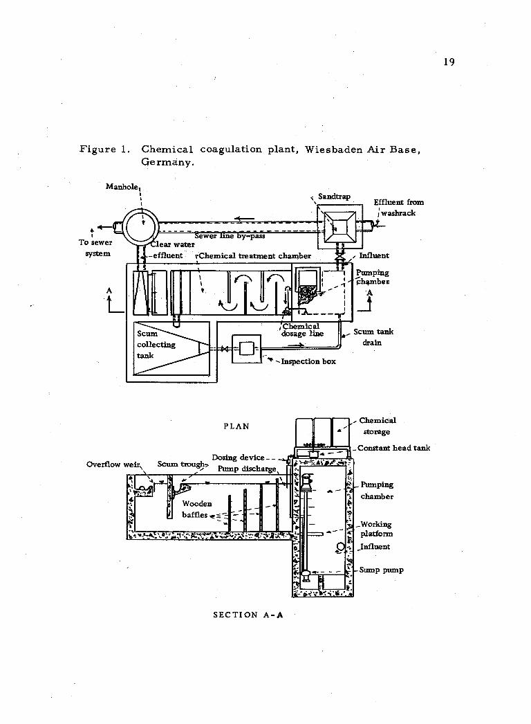
Figure 1. Chemical coagulation plant, Wiesbaden Air Base, Germany.
Manhole,
To sewer system
Sandtrap
___ ______T in 10, Sewer line by -pass
lean water -effluent rChemical treatment chamber f Influent
Effluent from
j washrack
Scum collecting tank
- I
Overflow weir\ Scum troughs
PLAN
Dosing device- Pump discharge
;Chemical dosage line
Inspection box
Pumping -0hamber
Scum tank drain
Chemical storage
Constant head tank
Pumping chamber
_Working platform
Influent
ump pump
SECTION A -A
19
4--- i
IC1
1 '
A
20
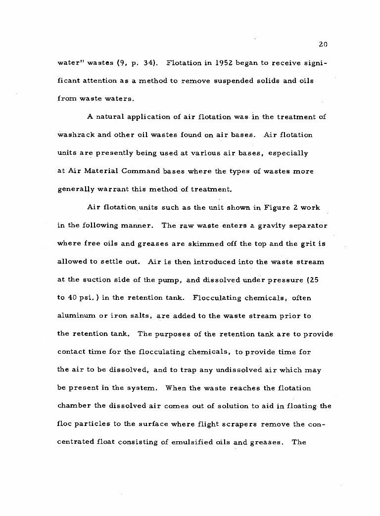
water" wastes (9, p. 34). Flotation in 1952 began to receive signi-
ficant attention as a method to remove suspended solids and oils
from waste waters.
A natural application of air flotation was in the treatment of
washrack and other oil wastes found on air bases. Air flotation
units are presently being used at various air bases, especially
at Air Material Command bases where the types of wastes more
generally warrant this method of treatment.
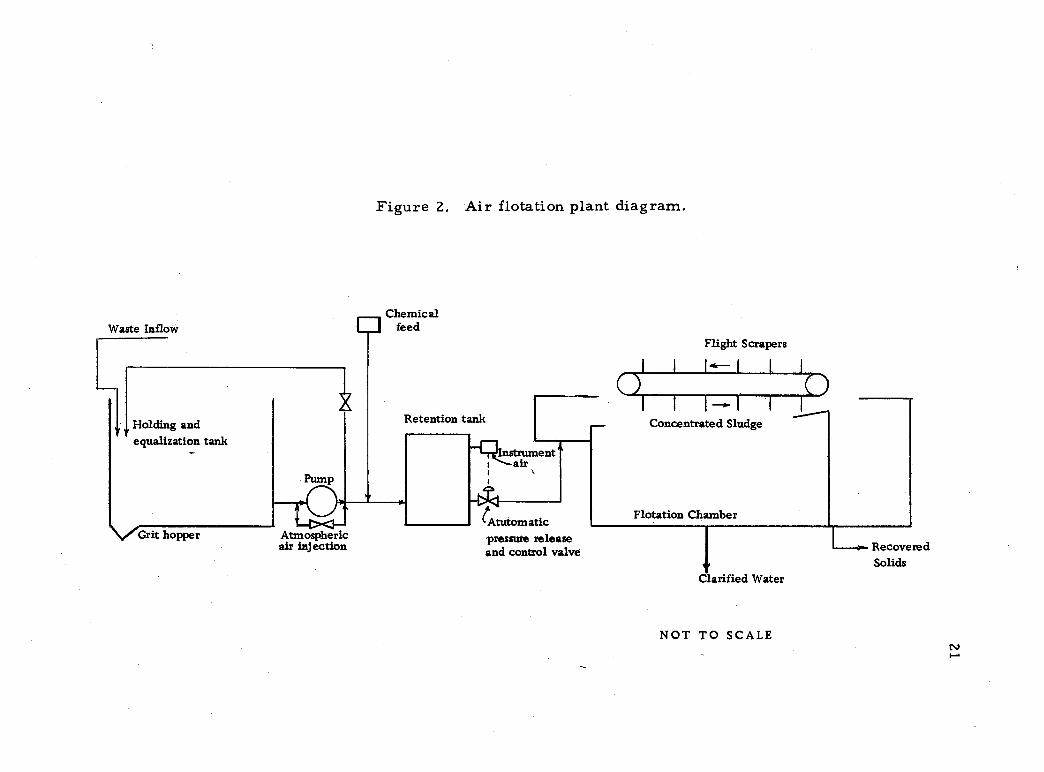
Air flotation units such as the unit shown in Figure 2 work
in the following manner. The raw waste enters a gravity separator
where free oils and greases are skimmed off the top and the grit is
allowed to settle out. Air is then introduced into the waste stream
at the suction side of the pump, and dissolved under pressure (25
to 40 psi. ) in the retention tank. Flocculating chemicals, often
aluminum or iron salts, are added to the waste stream prior to
the retention tank. The purposes of the retention tank are to provide
contact time for the flocculating chemicals, to provide time for
the air to be dissolved, and to trap any undissolved air which may
be present in the system. When the waste reaches the flotation
chamber the dissolved air comes out of solution to aid in floating the
floc particles to the surface where flight scrapers remove the con-
centrated float consisting of emulsified oils and greases. The
Waste Inflow
Holding and equalization tank
Grit y hopper
Pump
Figure 2. Air flotation plant diagram.
ElChemical feed
Retention tank
Atmospheric air injection
r Instrument air
I;4:l tAtutomatic pressure release and control valve
Flight Scrapers
I I
I I--- I I _ Concentrated Sludge
Flotation Chamber
Clarified Water
NOT TO SCALE
a Recovered Solids
(,I 1 1C
I
O I
22
clarified water is withdrawn from near the bottom of the flotation
tank.
Lagoons Secondary settling or lagooning has been used primarily
for secondary treatment of aircraft washrack wastes. At some air
bases in the southwest where washrack waste flows were small,
the lagoons were used as primary or evaporation lagoons.
In aerobic lagoons carbonaceous matter is oxidized by
aerobic bacteria to carbon dioxide which is used by the algea for
photosynthesis. The algea in turn supply oxygen to the aerobic
bacteria. "With oil wastes, the organic constituents are converted
to algea or are directly oxidized to the extent that they physically
separate from the waste water either by rising or settling" (2,
p. 51).
Filtration Other methods such as vacuum filtration and sand
or hay filtration were discussed by the American Petroleum
Institute (2, p. 40). According to the available literature, filtration
was not generally used as a method for treating washrack wastes.
However, F. A. Sanders, Lt. Col. USAF (18, p. 387) reported that
at Kelly Field AFB industrial oil wastes including washrack wastes,
following coagulation with alum to remove emulsified oils, were
passed through percolation filters before final sedimentation.
The American Petroleum Institute (2, p. 41) states that slow
23
sand filters operated in the two to ten mgad range but would clog
extremely fast when the turbidity exceeded 30 -50 ppm.
24
SURVEY OF CURRENT WASHRACK INSTALLATIONS AND TREATMENT FACILITIES AT AIR FORCE BASES
IN THE UNITED STATES
Aircraft Washrack Wastes Questionnaire
A questionnaire and letter of explanation were sent to 130
Air Force bases in the United States requesting information about
their methods of treating washrack wastes. Replies from 50 percent
of the contacted bases supplied the material for this section.
The information received was compiled into a description of
the facilities and operations for each air base. The descriptions
are arranged in alphabetical order according to the name of the
base, assigned an index number, and are included in Appendix C.
Table 5 serves as both a cross reference index and a summary of the
questionnaire information. For example, item 1 (c) in Table 5
shows that nine Air Force bases make use of gravity separation
followed by air flotation to treat their aircraft washrack wastes.
The index numbers refer to the descriptions in Appendix C and
indicate the air bases using this treatment method.
The questionnaire supplied the desired answers except in
a few cases. A copy of the questionnaire and a list of suggested
modifications have been included in Appendix C.
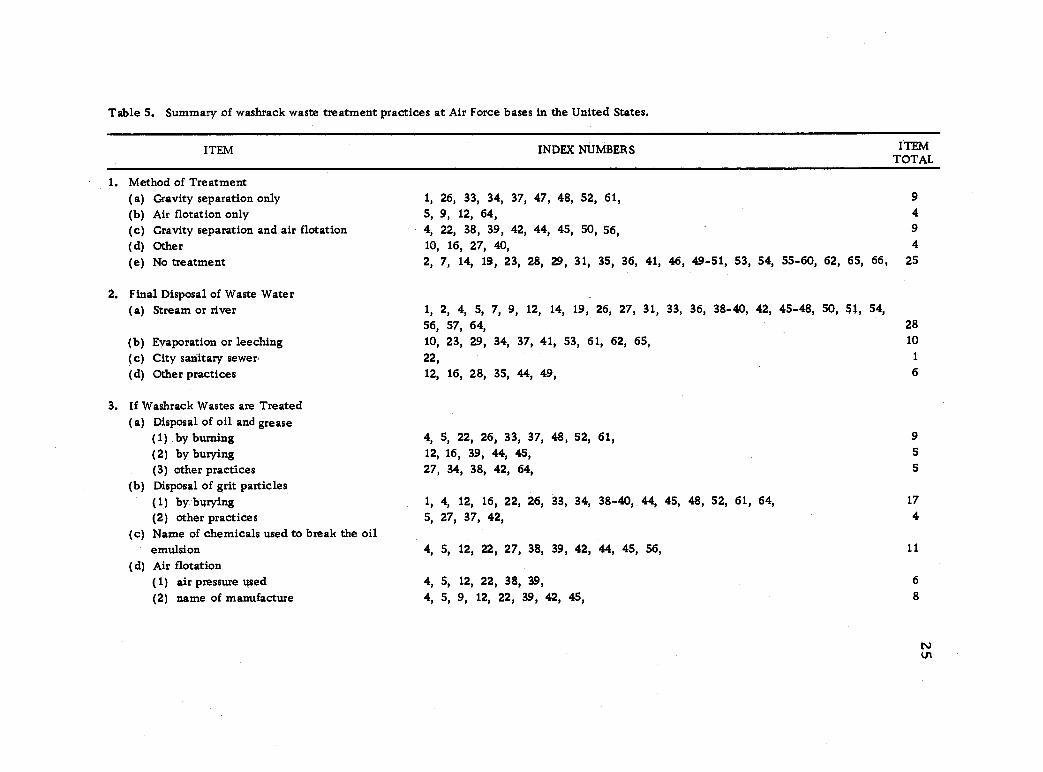
Table 5. Summary of washrack waste treatment practices at Air Force bases in the United States.
ITEM INDEX NUMBERS ITEM TOTAL
1. Method of Treatment (a) Gravity separation only (b) Air flotation only (c) Gravity separation and air flotation (d) Other
1,
5,
4,
10,
26, 33, 34, 37, 47, 48, 52, 61, 9, 12, 64, 22, 38, 39, 42, 44, 45, 50, 56,
16, 27, 40,
9
4 9
4
(e) No treatment 2, 7, 14, 19, 23, 28, 29, 31, 35, 36, 41, 46, 49-51, 53, 54, 55-60, 62, 65, 66, 25
2. Final Disposal of Waste Water (a) Stream or river 1, 2, 4, 5, 7, 9, 12, 14, 19, 26, 27, 31, 33, 36, 38-40, 42, 45-48, 50, 51, 54,
56, 57, 64, 28
(b) Evaporation or leeching 10, 23, 29, 34, 37, 41, 53, 61, 62, 65, 10
(c) City sanitary sewer 22, 1
(d) Other practices 12, 16, 28, 35, 44, 49, 6
3. If Washrack Wastes are Treated (a) Disposal of oil and grease
(1) by burning 4, 5, 22, 26, 33, 37, 48, 52, 61, 9
(2) by burying 12, 16, 39, 44, 45, 5
(3) other practices (b) Disposal of grit particles
27, 34, 38, 42, 64, 5
(1) by burying 1, 4, 12, 16, 22, 26, 33, 34, 38-40, 44, 45, 48, 52, 61, 64, 17
(2) other practices (c) Name of chemicals used to break the oil
5, 27, 37, 42, 4
emulsion (d) Air flotation
4, 5, 12, 22, 27, 38, 39, 42, 44, 45, 56, 11
(1) air pressure used 4, 5, 12, 22, 38, 39, 6
(2) name of manufacture 4, 5, 9, 12, 22, 39, 42, 45, 8
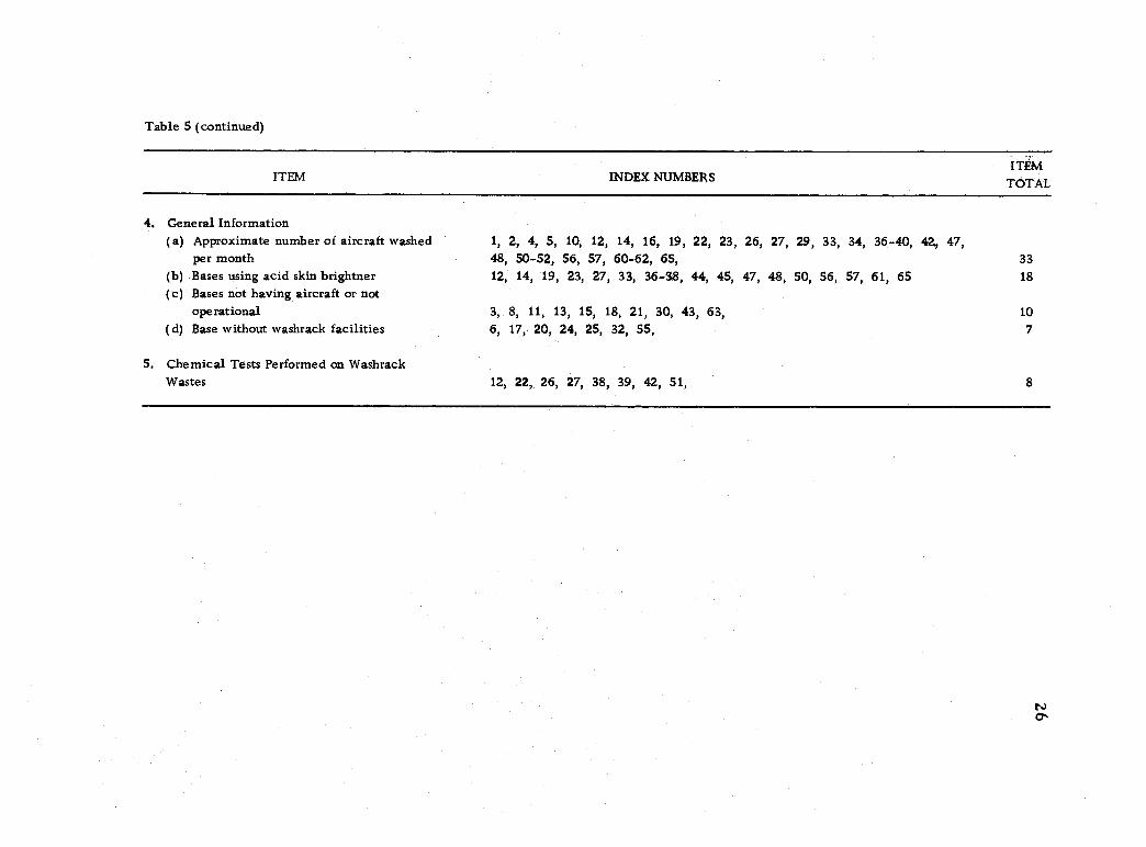
Table 5 (continued)
ITEM INDEX NUMBERS ITEM
TOTAL
4, General Information (a) Approximate number of aircraft washed 1, 2, 4, 5, 10, 12, 14, 16, 19, 22, 23, 26, 27, 29, 33, 34, 36-40, 42, 47,
per month 48, 50-52, 56, 57, 60-62, 65, 33 (b) Bases using acid skin brightner (c) Bases not having aircraft or not
12, 14, 19, 23, 27, 33, 36-38, 44, 45, 47, 48, 50, 56, 57, 61, 65 18
ope rational 3, 8, 11, 13, 15, 18, 21, 30, 43, 63, 10
(d) Base without washrack facilities 6, 17, 20, 24, 2S, 32, SS, 7
5. Chemical Tests Performed on Washrack Wastes 12, 22, 26, 27, 38, 39, 42, 51, 8
27
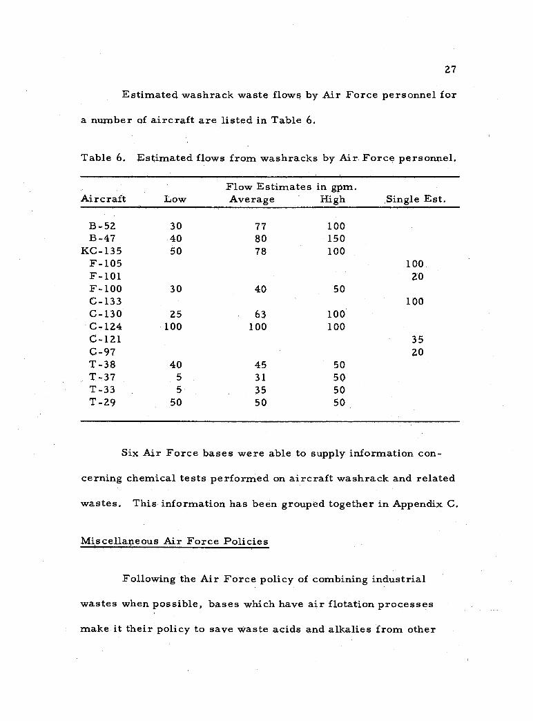
Estimated washraçk waste flows by Air Force personnel for
a number of aircraft are listed in Table 6.
Table 6. Estimated flows from washracks by Air Force personnel.
Aircraft Low Flow Estimates in gpm. Average High Single Est.
B-52 30 77 100 B-47 40 80 150
KC-135 50 78 100 F-105 100 F-101 20 F-100 30 40 50 C-133 100 C-130 25 63 100 C-124 100 100 100 C-121 35 C-97 20 T-38 40 45 50 T-37 5 31 50 T-33 5 35 50 T-29 50 50 50
Six Air Force bases were able to supply information con-
cerning chemical tests performed on aircraft washrack and related
wastes. This information has been grouped together in Appendix C.
Miscellaneous Air Force Policies
Following the Air Force policy of combining industrial
wastes when possible, bases which have air flotation processes
make it their policy to save waste acids and alkalies from other
28
base operations. The waste acids play a part in cracking the oil -
solvent -water emulsions and alkalies a part in pH control.
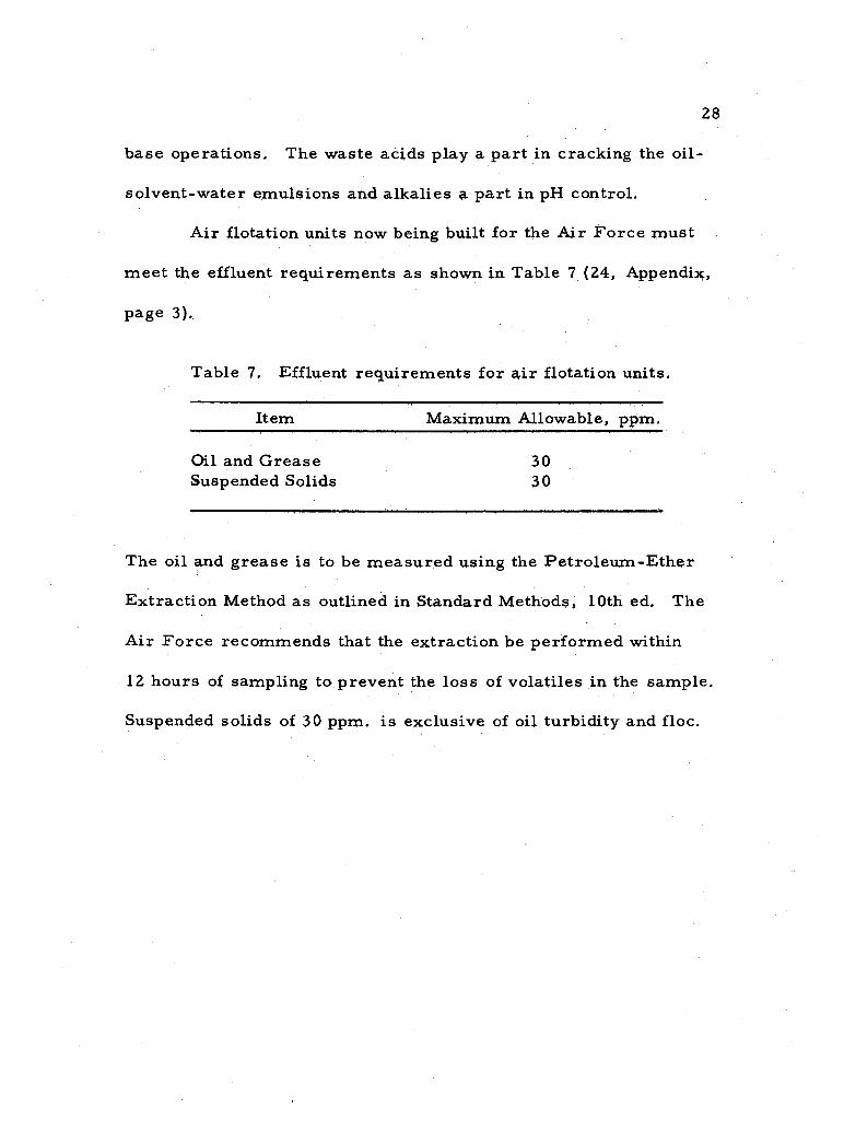
Air flotation units now being built for the Air Force must
meet the effluent requirements as shown in Table 7 (24, Appendix,
page 3). ,
Table 7. Effluent requirements for air flotation units.
Item Maximum Allowable, ppm.
Oil and Grease 30 Suspended Solids 30
The oil and grease is to be measured using the Petroleum -Ether
Extraction Method as outlined in Standard Methods, 10th ed. The
Air Force recommends that the extraction be performed within
12 hours of sampling to prevent the loss of volatiles in the sample.
Suspended solids of 30 ppm. is exclusive of oil turbidity and floc.
29
ANALYSIS OF WASHRACK WASTES AND THE TREATMENT FACILITY AT PORTLAND AFB, OREGON
Introduction
Portland Air Force Base is situated on the south side of a
reclaimed Columbia River flood plane within the city limits of
Portland, Oregon. The runways of the base are used jointly by the
337th Fighter Group, 939th Troop Carrier Squadron, Oregon Air
National Guard, and the Portland International Airport. The climate
of the area is moderate with a mean annual rainfall of about 35 inches
occurring for the most part during the months of October through
April. Average temperatures vary from 750 F in the summer to 360
F in the winter. Frost penetration seldom exceeds three inches,
The base is drained by a series of open ditches, storm drains and
small sloughs which all eventually reach the Columbia River. Flow
in the ditches and sloughs is controlled primarily by the ground
water table, Ponding and reversal of flow occurs frequently in the
drainage ditches.
Prior to July of 1963, only the Oregon Air National Guard
of the three military flying groups at Portland Air Force Base
provided any treatment of washrack wastes. At the 337th Fighter
Group and 939th Troop Carrier Squadron washing sites, the washrack
30
wastes drained from the aprons into the open ditches and sloughs.
Standing oils and solvents produced unsightly conditions and extreme
fire hazards, A small gravity oil separator at the Oregon Air
National Guard washrack removed the free oils and greases. The
effluent which contained only emulsified oils was discharged to a
nearby slough.
On July 24, 1963, a 5, 000 gallon skimming tank or gravity
oil separator for use by the 337th Fighter Group and the 939th
Troop Carrier Squadron was completed. The design flow of 400
gpm. for the gravity oil separator was based on a flow of 30 gpm.
from the washing operation and a storm flow of 363 gpm. The storm
flow was arrived at by considering a storm frequency of two years
with an intensity of 1.4 inches per hour and a maximum time of
concentration on the apron of ten minutes. Figure 3 is a drawing
of the gravity oil separator.
The effluent from the newly completed gravity separator
flows through a storm sewer to one of the drainage ditches. Free
oils trapped by the gravity separator will be burned or buried. At
present, no attempt is made to crack the emulsified oils. The
wastes which drain from the washing apron contain, oils, greases,
grit, paint strippings, alkaline water -base cleaner, acid cleaner or
skin brightner, paint stripper, and solvents similar to kerosene.
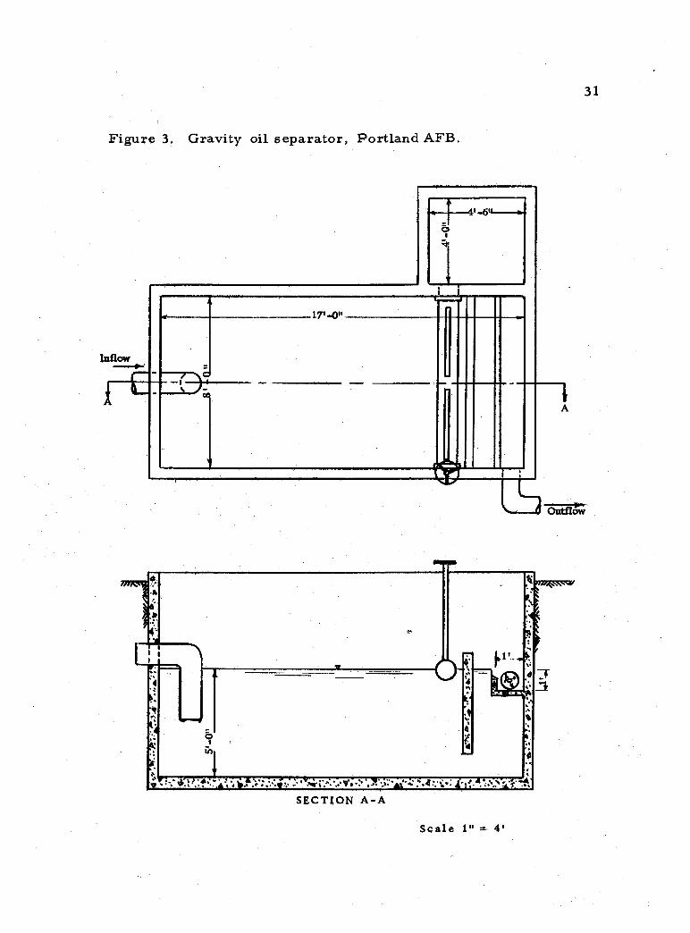
Figure 3. Gravity oil separator, Portland AFB.
4'6"
Inflow
X
ö
17'-O"
q
i
M
4
..:'it¡,,t. .`O.`.w'L.° r'-ifs''i-w;'.d:'¡.
Arrd741/4"4v
.;s\s. SECTION A -A
Scale 1"
31
..-
' a
= 4'
32
During the washing operation, the solvents are used to remove
heavy greases from areas such as engine cowlings and wheel
assemblies. Approximately ten C -119 aircraft are washed each
month. The washing procedure for the C -119 involves the spraying
of a small area of the aircraft with an alkaline, water -base cleaner,
brushing the sprayed area, and then rinsing the area down using an
1 -1/4 inch hose. The procedure is repeated until the complete air-
craft has been cleaned. Following washing, an acid skin brightner
is applied to corroded spots, brushed, and then rinsed off.
Method of Study and Experimental Design
Four tests, BOD. , oil and grease, suspended and total
solids, and flow measurements were chosen to determine the wash-
rack waste characteristics and to measure the efficiency of the
gravity separator used by the Fighter Group and Troop Carrier
Squadron.
The first step involved determining modifications of the four
above mentioned tests in order to make them suitable for determina-
tions involving small concentrations of oils, greases, and solvents
in waste water. Once analytical methods were formulated, and
laboratory proficiency was obtained, tests were conducted on waste
samples from the influent and effluent of the gravity separator during
33
aircraft washings.
Analytical Methods
Biochemical Oxygen Demand. The five day, 20o C, bio-
chemical oxygen demand of the aircraft washrack wastes was
determined as outlined in Standard Methods (4, p. 309) using the
Alsterberg azide modification of the Winkler method to measure the
dissolved oxygen. An acclimated seed was maintained by regularly
feeding small amounts of the alkaline, water -base cleaning solvent
and other solvents present in the washrack wastes to a stock culture.
The procedure for growing the modified BOD. seeding material has
been included in Appendix B.
Oil and Grease. There are many methods available to test
for oily matter in industrial waste waters. Attempts at standardiza-
tion of these methods have not met with too much success. The ASTM
Joint Committee on Uniformity of Methods of Water Examination
(5, D 1340 - 60, p. 490) stated that... "uniformity of methods for
the determination of grease and oily matter is not practicable on the
basis of present technical knowledge. " The four most popular
methods being presently used to measure oil in water appeared to be
the reflux distillation method, the infrared spectrophotometry method,
the extraction -evaporation method, and the direct extraction -
pycnometer method.
34
These four methods would probably produce different
results; however, the results of any one method would be consistent
provided the extraction solvent remained the same. According to
ASTM (5, p. 490) the solvents most commonly used were hexane,
petroleum ether, benzene, chloroform, or carbon tetrachloride.
Each of these solvents has a particular affinity for specific greases
and oils which may be of vegetable, mineral, or animal origin.
The definition of grease and oily matter due to the above
consideration, must be based on the procedure used.
Reflux Distillation Both the American Petroleum Institute (3,
API 731 -53) and the American Society for Testing and Materials
(5, ASTM D 1340 -60) have published reflux distillation methods for
measuring small amounts of greases and oils in waste waters. The
two methods are essentially the same. In both cases the sample is
refluxed through a trap which collects the volatile oily matter for
volumetric measurement. The remaining sample is extracted with
successive applications of solvent using mechanical agitation. The
API method requires that benzene be used as the extraction solvent,
whereas the ASTM method permits the use of benzene, chloroform,
or carbon tetrachloride. After separating the solvent layer from
the water, the extracts are distilled to remove the solvent. The
residue is cooled and weighed.
35
Substances such as alcohols, phenolics and organic acids
in addition to gasoline, fuel oil and hydrocarbons are measured.
The API method provides a correction for organic acids.
ASTM (5, p. 491) defines oily matter as... "Hydrocarbons,
hydrocarbon derivatives, and all liquid or unctuous substances that
have boiling points of 900 C or above and are extractable from water
a pH 5. 0 or lower using benzene as solvent."
These two methods, by API and ASTM, are reported to
measure better than 90 percent of the oily matter present, when the
cut point between volatile and nonvolatile oily matter lies in the 230°
to 260e C boiling range.
Extraction- evaporation. Standard Methods (4, p. 185) recom-
mends an extraction - evaporation method for measuring small
amounts of grease and oily matter in water.
The procedure involves using petroleum ether solvent under
acid conditions to extract dissolved or emulsified oils and greases. o
After extraction, the petroleum -ether is evaporated at 70 C through
a condenser. The remaining residue is cooled, weighed, and
reported as oil.
Infrared Spectrophotometry. R. G. Simard et al. (20, p. 1384)
explains that the infrared speçtrophotometry method for determining
oils is based on "bro#nination" of the phenols and oils in the water
-
36
sample. Oil is determined in a carbon tetrachloride extraction
from the phenol extraction (bromination) by optical density measure-
ments in the 3. 4 micron region. The API Committee on Analytical
Research (1, p. 1682) reports that this method is reliable for oil
concentrations as low as 0.1 ppm. with a standard deviation of
less than ten percent. The deviations, API reports, seem to be
caused by the variation in the absorptivity of different oil samples
at 3. 4 microns.
Direct Extraction -Pycnometer. The direct extraction -
pycnometer method as developed by Levine, Maps and Roddy (15,
p. 1840) is based...
on the fact that carbon tetrachloride containing a small amount of oil will weigh less than an equal volume of pure carbon tetrachloride. The difference in weight is the difference between the weight of the oil dissolved in the carbon tetrachloride and the weight of the volume of solvent equal to that of the oil,
The amount of oil in the water is then calculated directly based on
the assumption of an average specific gravity of the oil. The direct
extraction -pycnometer method is sensitive to ten ppm.
Measurement of Oil and Grease. Each of the four methods has
its own particular advantages and disadvantages. Considering (1)
the type of oil waste generally found on Air Force bases, (2) the
laboratory space and apparatus available, (3) the frequency of testing
required, (4) the time required, and (5) availability of trained
-
37
personnel, a modification of the extraction- evaporation method as
outlined in Standard Methods (4, p. 185) was developed.
The modified extraction- evaporation procedure is included
in Appendix B.
Suspended and Total Solids. A method outlined by the
American Petroleum Institute (3, API method 709 -53) was used to
measure suspended and total solids in aircraft washrack wastes.
The total solids were found by adding the results of the suspended
and dissolved solids determinations. The API defined suspended
solids as those solids remaining after the gooch crucible had been
rinsed with 30 ml. of distilled water and 60 ml. of chloroform. The
dissolved solids, in turn, were determined by evaporating the gooch
filtrate excluding the rinsings. Oils not lost in the evaporation of
the filtrate were included as dissolved solids.
Experimental Procedure
Evaluation of. Test Procedures. A series of tests were per-
formed to evaluate the BOD. and oil determination tests. The
criteria used to evaluate the BOD. testing procedure was the
consistency of results. For the oil determination tests, a series
of ten samples were set up with known concentrations of the solvents
used at Portland AFB. To duplicate the emulsion effect caused by
38
the alkaline, water -base cleaner, one mililiter of one gram per
liter ABS solution was added to each separatory funnel. The
separatory funnels containing a known concentration of solvent and
one ml. of ABS solution were shaken for two minutes and oil deter- -.
minations as outlined in the previous section were performed.
Based on the ten oil determinations an average time period
of 25 minutes was used for extending the tangent line in subsequent
oil determinations.
Washrack Waste Test Procedure. At periodic intervals
composite samples of the influent and effluent flow to and from the
gravity oil separator were taken, and the constituents making up the
influent were noted. Oil concentration, BOD. , total solids, and
suspended solids tests were then performed. The washrack waste
samples were derived solely from washing and paint stripping C -119
aircraft. Depending on the dirtiness of the aircraft and the type of
maintenance to be performed, an individual sampling period covering
the complete washing and rinsing time ran from two to six hours.
The effluent flow from the gravity separator was measured
using a seven day automatic stage recorder and a fixed 90° V -notch
weir.
39
Experimental Results
Waste Analysis. The results of the analyses of the treated
and untreated washrack wastes are presented in Table 8. The
"waste composition" portion of the table indicates the type of
cleaning operation being performed and the probable constituents
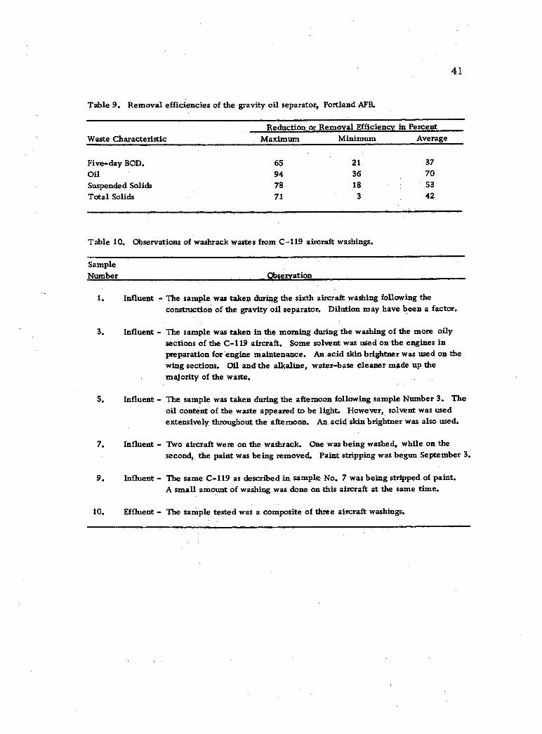
in the wash water at the time of sampling. From the test results
listed in the lower portion of Table 8 under "waste characteristics, "
the maximum, minimum, and average percent reduction or removal
is shown in Table 9. To link "waste composition" with "waste
characteristics" as shown in Table 8, a brief description of the
washing operations at the time of sampling are included in Table 10.
The sample numbers of Table 8 correspond to those in Table 10.
After the four waste analysis tests were performed, the
wastes were allowed to stand for approximately one month. The
treated waste samples or effluent samples showed no signs of free,
floating oils at the end of this period.
Flow Rates. Effluent flow measurements, Table 11, were o computed from stage changes over a 90 V -notch weir (13, p. 4 -13).
Due to the washing procedure and the damping effect of the gravity
oil separator, the influent flow rate would be somewhat higher than
the maximum effluent discharge rate shown in Table 11. The
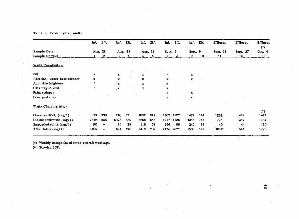
Table 8. Experimental results.
Inf. Eff. Inf. Eff. Inf. Eff. Inf. Eff, Inf. Eff. Effluent Effluent Effluent (t)
Sample Date Aug. 23 Aug. 28 Aug. 28 Sept. 6 Sept. 9 Sept. 18 Sept. 27 Oct. 4 Sample Number 1 2 3 4 5 6 7 8 9 10 11 12 13
Waste Composition
Oil x x x x x Alkaline, water -base cleaner x x x x x Acid skin brightner ? x x x
Cleaning solvent ? x x x
Paint stripper x x Paint particles x x
Waste Characteristics (*)
Five -day BOD. (mg/1) 533 350 740 521 1032 812 3302 1127 1477 514 1252 489 1471 Oil concentration (mg/1) 1449 656 6398 580 2258 545 1757 1125 4248 243 724 249 1131
Suspended solids (mg /1) 90 - 34 28 110 51 266 80 240 54 40 44 125
Total solids (mg /1) 1105 - 694 498 2413 702 2126 2071 1505 697 1012 561 1775
(t) Weekly composite of three aircraft washings. ( *) Six -day BOD.
41
Table 9. Removal efficiencies of the gravity oil separator, Portland AFB.
Waste Characteristic Reduction or Removal Efficiency in Percent
Maximum Minimum Average
Five -day BOD. 6$ 21 37
Oil 94 36 70 Suspended Solids 78 18 53
Total Solids 71 3 42
Table 10. Observations of washrack wastes from C -119 aircraft washings.
Sample Number Observation
1. Influent ,- The sample was taken during the sixth aircraft washing following the construction of the gravity oil separator. Dilution may have been a factor.
3. Influent - The sample was taken in the morning during the washing of the more oily sections of the C -119 aircraft. Some solvent was used on the engines in preparation for engine maintenance. An acid skin brightner was used on the wing sections. Oil and the alkaline, water base cleaner made up the majority of the waste.
5, Influent - The sample was taken during the afternoon following sample Number 3. The oil content of the waste appeared to be light. However, solvent was used extensively throughout the afternoon. An acid skin brightner was also used.
7. Influent - Two aircraft were on the washrack. One was being washed, while on the second, the paint was being removed. Paint stripping was begun September 3.
9. Influent - The same C -119 as described in sample No. 7 was being stripped of paint. A small amount of washing was done on this aircraft at the same time.
10. Effluent - The sample tested was a composite of three aircraft washings.
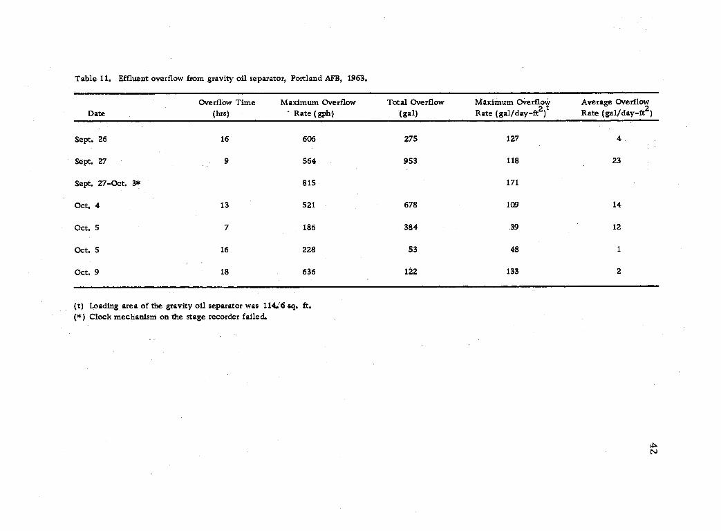
Table 11. Effluent overflow from gravity oil separator, Portland AFB, 1963.
Date Overflow Time
(hrs) Maximum Overflow
Rate (gph) Total Overflow
(gal) Maximum Overflow Rate (gal /day -ft2)t
Average Overflow Rate (gal /day -ft2)
Sept. 26 16 606 275 127 4
Sept. 27 9 564 953 118 23
Sept. 27 -Oct. 3* 815 171
Oct. 4 13 521 678 109 14
Oct. 5 7 186 384 39 12
Oct. 5 16 228 53 48 1
Oct. 9 18 636 122 133 2
(t) Loading area of the gravity oil separator was 1140'6 -sq. ft. ( *) Clock mechanism on the stage recorder failed.
-
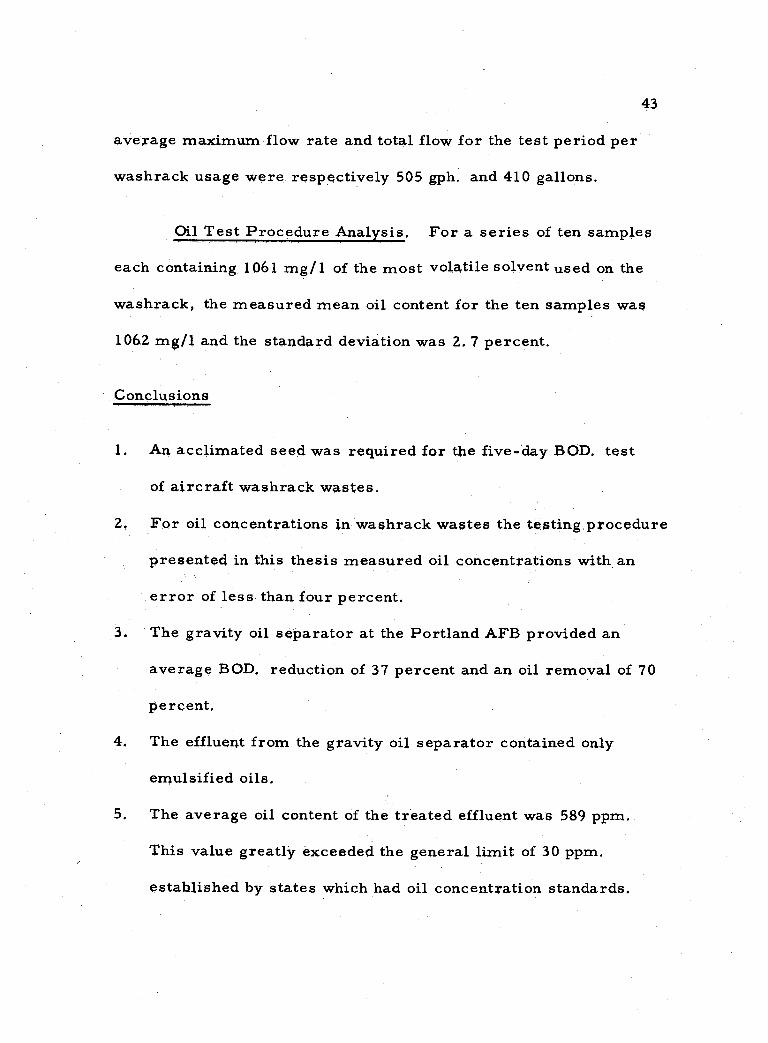
43
average maximum flow rate and total flow for the test period per
washrack usage were respectively 505 gph. and 410 gallons.
Qil Test Procedure Analysis. For a series of ten samples
each containing 1061 mg /1 of the most volatile solvent used on the
washrack, the measured mean oil content for the ten samples was
1062 mg /1 and the standard deviation was 2. 7 percent.
Conclusions
1. An acclimated seed was required for the five -day BOD. test
of aircraft washrack wastes.
2, For oil concentrations in washrack wastes the testing procedure
presented in this thesis measured oil concentrations with an
error of less than four percent.
3. The gravity oil separator at the Portland AFB provided an
average BOD. reduction of 37 percent and an oil removal of 70
percent.
4. The effluent from the gravity oil separator contained only
emulsified oils.
5. The average oil content of the treated effluent was 589 ppm.
This value greatly exceeded the general limit of 30 ppm.
established by states which had oil concentration standards.
44
6. An average of 410 gallons of water was required to wash a C -119
aircraft at Portland AFB.
Recommendations for Further Studies
1. Investigate the possibility of using activated sludge or trickling
filter units to treat the washrack waste effluent from a gravity
oil separator,
2. Determine the characteristics of the washrack waste effluent
if air flotation or lagooning were used to remove the emulsified
oils.
3. Determine the oil and BOD. concentration of the alkaline, water -
base cleaner, acid skin cleaner, and paint stripper for con-
centrations found at washracks,
Investigate using an absorbent material which has a strong
affinity for oil as filter media.
5. Study further the oil concentration testing procedure as outlined
in this thesis by investigating such factors as:
a. evaporation rates of different solvents and oils,
b. the effect that the air flushing rate has on the time rate of evaporation of chloroform and extracted oils,
c. measurement of oil concentrations below 100 mg /1,
d. the effect that different water bath temperatures has on the results.
4.
-
45
BIBLIOGRAPHY
1. American Petroleum Institute, Committee on Analytical Research, Division of Refining. Methods for determining hydrocarbons and phenols in water. Analytical Chemistry 25: 1681 -1684. 1953.
Z. American Petroleum Institute. Manual on disposal of refinery wastes. Vol. 1, Waste water containing oil. 6th ed. New York, 1959. 92 p.
3. American Petroleum Institute. Manual on disposal of refinery wastes. Vol. 4, Sampling and analysis of waste water. 2nd ed. New York, n. d.
4, American Public Health Association, et al. Standard methods for examination of water and waste- water. 11th ed. New York, 1962. 626 p.
5. American Society for Testing Materials. Committee D -19 on Industrial Water and Industrial Waste Water. 2nd ed. Philadelphia, 1962. 762 p.
6. Bolton, Frederic Merret. The removal of beet waste color by activated sludge. Master's thesis. Corvallis, Oregon State University, 1963. 30 numb. leaves.
7, Cheap disposal plant helps Air Force get rid of heavy petroleum wastes. Engineering News -Record 154:40. Feb. 3, 1955.
8, Coulter, James B. , Francis M. Crompton, and Joseph F. Lagnese. Emulsified oil waste: an Air Force problem. In: Eleventh Industrial Waste Conference, Purdue University, May 15, 16,& 17, 1956. p. 99 -113. (Purdue University. Engineering Extension Dept. Extension series no, 91)
9, D'Arcy, Nicholas A. Dissolved -air flotation separates oil from waste water. Proceedings of American Petroleum Institute 31(Division of Refining, M[IIIJ):34 -44. 1951.
-
46
10. Gloyna, E. F. , R. F. Constock, and C. F. Renn. Rotary tubes as experimental trickling filters. Sewage and Industrial Wastes 24:1355 -1357. 1952.
11. Great Britain. Department of Scientific and Industrial Research. Water pollution research, 1960. London, H. M. Stationary Office, 1961. 128 p.
12. Great Britain. Department of Scientific and Industrial Research. Water pollution research, 1955. London, H. M. Stationary Office, 1956. 88 p.
13. King, Horace Williams. Handbook of Hydraulics, 4th ed. New York, McGraw -Hill, 1954. 822 p.
14. Koruzo, John E. Waste treatment facilities at United States Air Force installations. Sewage and Industrial Wastes 29: 281 -286. 1957.
15. Levine, W, S. , G. S. Mapes, and M. J. Roddy. Direct extraction -pyconometer methods for oil content of refinery effluents. Analytical Chemistry 25:1840- 1.844. 1953.
16, Mahood, Edward J. Chemical coagulation and pressure flotation for aircraft oil wastes. Wastes. Engineering 31: 434 -437. 1960.
17. Rohlich, G. A. Application of air flotation to refinery waste waters. Industrial and Engineering Chemistry 46:304 -308. 1954.
18. Sanders, F. A. , Lt. Col. USAF. Combating oil and metal plating waste problems. -at Kelly Air Force Base. In: Seventh Industrial Waste Conference, Purdue University, May 7, 8, &
9, 1952. p. 382 -394. (Purdue University. Engineering Extension Dept. Extension series no. 79)
19. Setter, L. R. et al. Disposal of wastes from the cleaning of airplanes. Cincinnati, Ohio, 1953. 50 p. (U. S. Public Health Service. Robert A. Taft Sanitary Engineering Center. Report no. 3 on contract no. AF -33 (038) 22425 with the Air Material Command, U. S. Air Force)
-
47
20. Simard, R. G. et al. Infrared spectrophotometric deter- mination of oil and phenols in water. Analytical Chemistry 23: 1384 -1387, 1951.
21. U. S. Air Force. Cleaning of aeronautical equipment. August 16, 1962. [6 p.] (Technical manual T. O. 1 -1 -1)
22. U. S. Aix Force. Installation -- general maintenance and operation of sewage and industrial waste plants and systems. January 5, 1959. 387 p. (Air Force manual 85 -14)
23. U. S. Air Force, McClellan Air Force Base. Water pollution control. Sacramento, April 1962. 13 p. (AF, SMAMA)
24. U. S. Air Force. Sewage, refuse, and industrial waste, civil engineering construction ch. 6. June 30, 1960. 57 p. (Air Force Manual 88 -11)
25. U. S. Public Health Service. Robert A. Taft Sanitary Engineering. Center. Disposal of airplane wash waste. Cincinnati, 1955. 58 p. (Publication of the Process Development Studies)
APPENDICES
48
APPENDIX A
Summary of Military Specifications for Cleaning Compounds
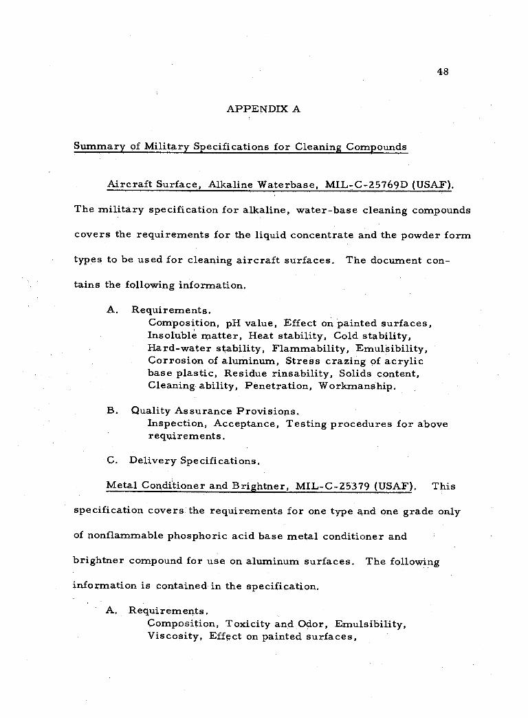
Aircraft Surface, Alkaline Waterbase, MIL- C- 25769D (USAF).
The military specification for alkaline, water -base cleaning compounds
covers the requirements for the liquid concentrate and the powder form
types to be used for cleaning aircraft surfaces. The document con-
tains the following information.
A. Requirements. Composition, pH value, Effect on painted surfaces, Insoluble matter, Heat stability, Cold stability, Hard -water stability, Flammability, Emulsibility, Corrosion of aluminum, Stress crazing of acrylic base plastic, Residue rinsability, Solids content, Cleaning ability, Penetration, Workmanship.
Quality Assurance Provisions. Inspection, Acceptance, Testing procedures for above requirements.
C. Delivery Specifications.
Metal Conditioner and Brightner, MIL -C -25379 (USAF). This
specification covers the requirements for one type and one grade only
of nonflammable phosphoric acid base metal conditioner and
brightner compound for use on aluminum surfaces. The following
information is contained in the specification.
A. Requirements. Composition, Toxicity and Odor, Emulsibility, Viscosity, Effect on painted surfaces,
B.

49
Nonflammability, Immersion corrosion, Residual corrosion, Diffuse reflectance, Stress - crazing of acrylic base plastic, Cleaning characteristics.
B. Quality Assurance Provisions. Acceptance tests, Testing procedures for above requirements.
C. Delivery Specifications.
Source for Military Specifications. The civil engineering
office of a nearby Air Force base should be contacted for further
information regarding these military specifications.
Chemical Composition of Aircraft Cleaners
The cleaners are single phase, liquid emulsifiable cleaners
used to remove soil, grease, and oil from metal surfaces.
Lix 3852 Surface Cleaner :4
Aromatic hydrocarbon Caustic potash Emulsifying agents Glycol derivatives
50% min. 2. 75% min.
36% max. 10% max.
Lix 3852 is an emulsified petroleum product which requires additional dilution with PS - 661 material before using. Rinsing is with water. Federal Specifications list PS - 661 as "Solvent,- Dry Cleaning. II
4The information was taken from a letter dated 26 June 62; written to SSgt.Victor B. Skaar, 825th Medical Group, Little Rock AFB, Arkansas, from the Lix Corporation of Missouri, 300 West 80th Street, Kansas City 14, Missouri, Phone Delmar 3 -4464.
50
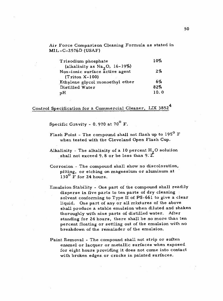
Air Force Comparison Cleaning Formula as stated in MIL -C -2576D (USAF)
Trisodium phosphate 10% (alkalinity as Na2O, 16 -19 %)
Non -ionic surface active agent 2% (Triton X -100)
Ethylene glycol monoethyl ether 6% Distilled Water 82% pH 10.0
Control Specification for a Commercial Cleaner, LIX 38524
Specific Gravity - 0. 970 at 70° F.
Flash Point - The compound shall not flash up to 195° F when tested with the Cleveland Open Flash Cup.
Alkalinity - The alkalinity of a 10 percent H2O solution shall not exceed 9. 8 or be less than 9.- 2.
Corrosion - The compound shall show no discoloration, pitting, or etching on magnesium or aluminum at 130° F for 24 hours.
Emulsion Stability - One part of the compound shall readily disperse in five parts to ten parts of dry cleaning solvent conforming to Type II of PS -661 to give a clear liquid. One part of any or all mixtures of the above shall produce a stable emulsion when diluted and shaken thoroughly with nine parts of distilled water. After standing for 24 hours, there shall be no more than ten percent floating or settling out of the emulsion with no breakdown of the remainder of the emulsion.
Paint Removal - The compound shall not strip or soften enamel or lacquer or metallic surfaces when exposed for eight hours providing it does not come into contact with broken edges or cracks in painted surfaces.
51
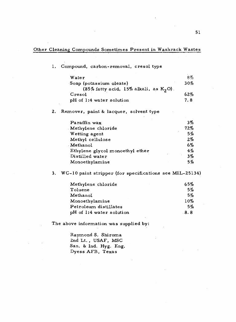
Other Cleaning Compounds Sometimes Present in Washrack Wastes
1, Compound, carbon - removal, cresol type
Water 8% Soap (potassium oleate) 30%
(85% fatty acid, 15% alkali, as K2O) Cresol 62% pH of 1:4 water solution 7. 8
2. Remover, paint & lacquer, solvent type
Paraffin wax 3% Methylene chloride 72% Wetting agent 5% Methyl cellulose 2% Methanol 6% Ethylene glycol monoethyl ether 4% Distilled water 3% Monoethylamine 5%
3. WC -10 paint stripper (for specifications see MIL -25134)
Methylene chloride 65% Toluene 5% Methanol 5% Monoethylamine 10% Petroleum distillates 5% pH of 1:4 water solution 8. 8
The above information was supplied by:
Raymond S. Shiroma 2nd Lt. , USAF, MSC San. & Ind. Hyg. Eng. Dyess AFB, Texas
52
APPENDIX B
Experimental Testing Procedures
Biochemical Oxygen Demand. The seed culture is started by
adding 30 ml. of raw sewage influent to one liter of tap water under
aeration. For a period of two weeks 10 ml. of feed are added each
day. For a second period of two weeks in addition to adding the
feed, one ml. of combined aircraft cleaners is added to the cultures
every two days. Foaming caused by the air agitation of the cleaner
is to be expected. At the end of four weeks the culture should be
ready to be used in BOD. determinations.
To prepare the seeded dilution water, remove 25 ml. of the
seed culture. Dilute to 250 ml. with distilled water. Blend the
diluted seed culture for one minute. Add to the unseeded dilution
water as prepared in Standard Methods (4, p. 319) five ml. of
blended seed per liter of dilution water. Seeded dilution water
should be used the same day it is made.
The feed as prepared by the following formula should be
remade every two weeks or when the feed becomes cloudy from
growths, The feed will last for longer periods if containers are acid
washed before using and the feed is kept at 5° C (6, p. 18). Refer to
Table 12 for feed formula.
53
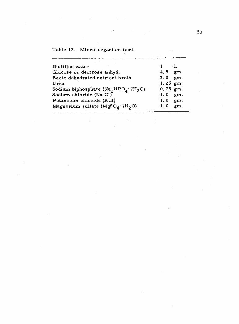
Table 12. Micro- organism feed.
Distilled water 1 1.
Glucose or dextrose anhyd. 4. 5 gm. Bacto dehydrated nutrient broth 3. 0 gm. Urea 1.25 gm. Sodium biphosphate (Na2HPO4. 7H2O) 0. 75 gm. Sodium chloride (Na C1) 1. 0 gm. Potassium chloride (KC1) 1. 0 gm. Magnesium sulfate (MgSO4. 7H2O) 1. 0 gm.
54
Oil and Grease. The following experimental procedure is
patterned after the extraction -evaporation method outlined in "Oil
and Grease" Standard Methods, 11th ed. , p. 185.
Measurement of Oil and Grease in Aircraft Washrack Wastes
General Discussion
Principles. The extraction- evaporation method as applied to aircraft washrack wastes embodies the following three steps: cracking the detergent -oil -water emulsion, extracting the oil fractions from the emulsion using an organic solvent, and evaporating the solvent to leave the oil residue.
Care must be exercised in choosing the extraction solvent and the evaporation temperature. As Standard Methods points out "Even lubrication oil fractions evaporate at a significant rate at the temperature which is necessary for removal of the last traces of the extraction solvent" (4, p. 185).
Sampling. Care should be taken that the sample is representative. Samples should be taken in clean, glass- stoppered bottles, previously washed with solvent and air dried before use, The bottles should not be completely filled, as a loss of floating oil may occur in stoppering. It is advisable to collect the desired quantity of sample in an oversized bottle that has previously been marked on the outside at the desired volume (4, p. 185).
Storage of Sample. Stored samples should be kept under refrigeration to inhibit bacterial activity. Acidifying the sample at this point may break the emulsion and cause more oil to cling to the sides of the container. Storage should be avoided if possible.
55
Apparatus
Water Bath. A distilled water bath capable of maintaining a water temperature of 84° C to 87° C should be used.
Separatory Funnel. The separatory should be 125 ml. in size. Stopcocks should be of the non - lubricating type or should have all greasy lubricants removed from the ground -glass surfaces. A special stopcock lubricant can be prepared (4, p. 186).
Weighing Balance. A balance accurate to one miligram is required.
Air Condenser. An air condenser of low actinic glass, 23 inches long, and with a T. S. joint is required.
Reagents
Sulfuric Acid Solution. One part concentrated sulfuric acid to one part water.
Chloroform. The boiling point is 62.2 0
C.
Procedure
1. Place 75 ml. of sample in a separatory funnel. If the sample added is the total sample originally taken, rinse sample bottle carefully with 3 ml. of chloroform and add the rinsing to the separa- tory funnel. If the sample added is a fraction of the total sample taken, agitate while with- drawing 75 ml. for the separatory funnel.
2. Add 1 ml. of 1 +1 H SO4 and 15 ml. of chloroform to the separatory funnel.
3. Shake the separatory funnel gently for three minutes.
4. Pass the entire contents of the separatory funnel through a glass funnel containing a cotton pad which has been previously saturated with chloroform.
56
Collect the filtrate in a second separatory funnel. Add 3 ml. of chloroform to the original separatory funnel, shake vigorously, drain through the cotton pad, and collect in the second separatory funnel. Taking the cotton pad in hand, rinse down the glass funnel thoroughly by squeezing the cotton pad until free of excess liquid. Also collect this washing in the second separatory funnel. The purpose of step four is to first filter out unwanted solids, and secondly, to break any emulsion which may form in the chloroform layer due to the shaking action in step three.
5. Drain the chloroform layer from the second separatory funnel into a previously cleaned, oven dried, and weighed 300 ml. T. S. jointed flask. Scum particles which may appear just above the chloroform layer should not be withdrawn with the chloroform layer.
6. Perform a second extraction by adding 15 ml. of chloroform to the sample after the first extraction has been completed. Shake gently for three minutes and follow with step four if necessary. Drain the chloroform layer into the flask containing the first extracted solvent.
7. Allow the separatory funnel to sit for five minutes. If further liquid (chloroform) appears below the water layer, withdraw this chloroform into the flask also.
8. Repeat steps 1 -7 with a second 75 ml. sample and add the extracted solvent portions to the flask containing the first extractions.
9. Attach the air condenser to the flask and place in an 84 -87° C water bath. Evaporate the chloro- form for 30 to 60 minutes or until 2 to 5 ml. of liquid still remain in the flask. At this point condensed liquid should still be draining down the condenser and back into the flask.
10. Remove the unit from the water bath and allow to cool for two minutes. Then remove the air condenser, and slowly blow dry filtered air into the
57
flask for one minute, and then weigh the flask. The weighing will be approximate due to the chloroform escaping from the flask.
11. Return dry filter air to flask for five minutes, then weigh the flask again.
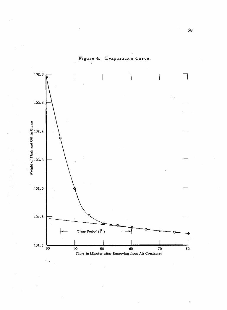
12. Plot the points on coordinate paper with axes of flask weight in grams vs. time after removing air condenser. The scale used on the vertical axis should be large enough to allow the plotting of points without estimation to one hundredth of a gram, See Figure 4, page 58 for an example curve.
13. Repeat items 11 and 12 until the curve has gone six points past its extreme change in slope.
14. Extend the constant slope portion back to the left as shown in Figure 4. From the point of tangency measure back along the horizontal axis a predetermined amount of time. (Refer to interpretation of results, page 59. )
15. The intersection of a vertical line lying a given number of minutes from the point of tangency and the tangent line is the weight of flask containing the oil residue when read on the vertical axis.
Calculation
The gain in weight of the flask is due to the oil and grease in the airplane washrack wastes.
where:
mg /1 (ppm.) of oil and grease = (a -b) 1000
a = weight of flask containing oil residue in mg. b = weight of flask empty (tare wt. ) in mg. c = volume of sample originally placed in
separatory funnel in ml. For this procedure c = 150 ml.
c
ti
102.8
102.6
58
Figure 4. Evaporation Curve.
..{
102.0
101.8
101.6 30
Time Period (ß
1
40 50 60 70 Time in Minutes after Removing from Air Condenser
80
w
á a
?
1 1 1 t
e 102. 4
59
Interpretation of Results
When reporting results the method of extraction and solvent used should be included.
To determine the period of time (p) to extend back from the point of tangency the preceding test should be performed on each of the washing solvents and oils known to be present in the waste stream. Ten tests should be run using a predetermined weight of a given solvent in each of the ten tests. Using the ex- tended tangent and the true solvent weight, an average time period and tangent slope for a particular solvent may then be determined,
For all subsequent tests of samples containing unknown amounts of given oils and solvents, the pre- determined standard tangent slopes and time periods will act as a guide for choosing the time period to extend back from the tangent point.
The rate at which air is bled into the flask should be kept constant for all tests once standard tangent slopes and time periods have been developed.
60
APPENDIX C
Aircraft Washrack Wastes Questionnaire
427 S. 5th Street Corvallis, Oregon 21 April 1963
SUBJECT: Analysis of Aircraft Washrack Wastes
TO: Installations Engineer
1. I am preparing a thesis in connection with my advanced course of study at Oregon State University pointing toward a Masters Degree in Civil Engineering (sanitary engineering specialty) under the AFIT program.
2. My thesis is concerned with the problems of treating aircraft washrack wastes. I am planning to study and evaluate some of the problems connected with using sedimentation separately or combined with air flotation as a method of removing the grit, solvents, and oil particles from the washrack wastes.
3. I would like to include in my thesis a summary of present operational methods of treating washrack wastes. If time permits, would you please fill out and return the enclosed questionnaire. Thank you.
DAVID R. EVANS 2nd Lt. , USAF
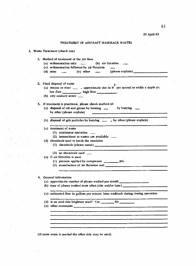
20 April 63
TREATMENT OF AIRCRAFT WASHRACK WASTES
I. Waste Treatment (check one)
61
1. Method of treatment at the Air Base
(a) sedimentation only (b) air flotation (c) sedimentation followed by air flotation (d) none _ (e) other - (please explain)
2. Final disposal of waste 3
(a) stream or river . approximate size in ft per second or width x depth at: low flow . high flow
(b) city sanitary sewer
3. If treatment is practiced, please check method of: (a) disposal of oil and grease by burning _ by burying
by other (please explain)
(b) disposal of grit particles by burying , by other (please explain)
(c) treatment of waste (1) continuous operation (2) intermittent as wastes are available
(d) chemicals used to break the emulsion (1) chemicals (please name)
(2) no chemicals used (e) If air flotation is used
(1) pressure applied by compressor psi. (2) manufacture of air flotation unit
4. General information (a) approximate number of planes washed per month (b) type of planes washed most often (size and /or type)
(c) estimated flow in gallons per minute from washrack during rinsing operation
(d) is an acid skin brightner used? Yes No (e) other comments
(if more room is needed the other side may be used)
-
- _
_
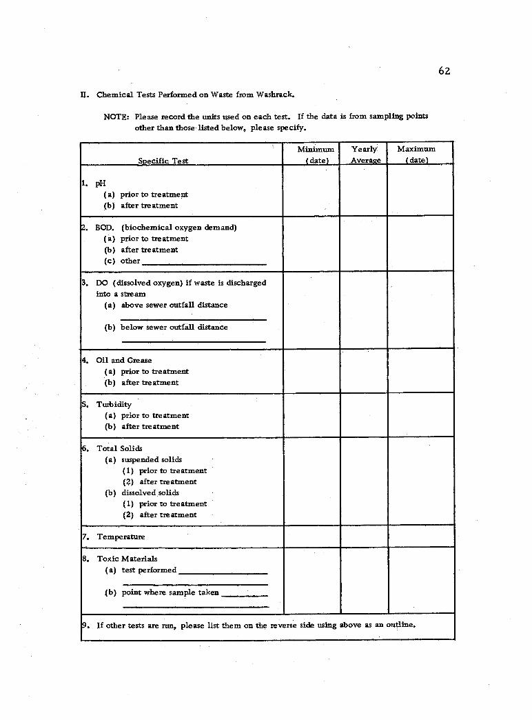
62
II. Chemical Tests Performed on Waste from Washrack.
NOTE: Please record the units used on each test. If the data is from sampling points other than those listed below, please specify.
Specific Test Minimum
(date) Yearly Average
Maximum (date)
1. pH
(a) prior to treatment (b) after treatment
2. BOD. (biochemical oxygen demand) (a) prior to treatment (b) after treatment (c) other
3, DO (dissolved oxygen) if waste is discharged into a stream
(a) above sewer outfall distance
(b) below sewer outfall distance
4. Oil and Grease (a) prior to treatment (b) after treatment
S. Turbidity (a) prior to treatment (b) after treatment
6. Total Solids (a) suspended solids
(1) prior to treatment (2) after treatment
(b) dissolved solids (1) prior to treatment (2) after treatment
7. Temperature
8. Toxic Materials (a) test performed
(b) point where sample taken
9. If other tests are run, please list them on the reverse side using above as an outline.
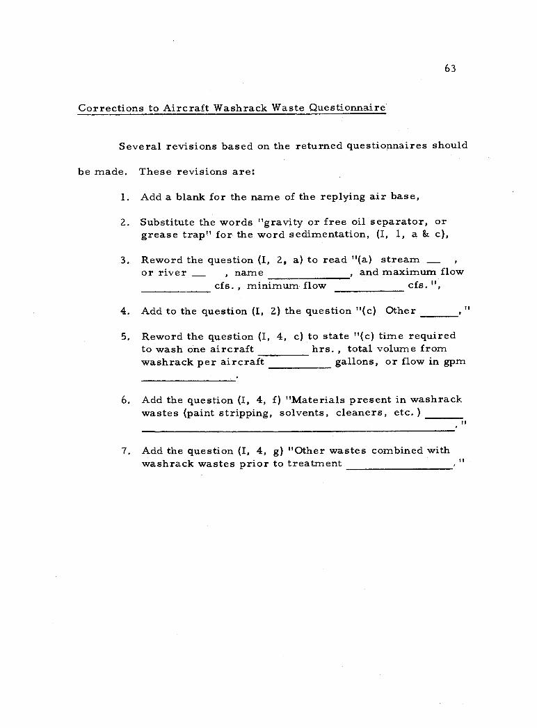
63
Corrections to Aircraft Washrack Waste Questionnaire
Several revisions based on the returned questionnaires should
be made. These revisions are:
1. Add a blank for the name of the replying air base,
2. Substitute the words "gravity or free oil separator, or grease trap" for the word sedimentation, (I, 1, a & c),
3. Reword the question (I, 2, a) to read "(a) stream or river , name , and maximum flow
cfs. , minimum flow cfs. ",
4. Add to the question (I, 2) the question "(c) Other
5. Reword the question (I, 4, c) to state "(c) time required to wash one aircraft hrs. , total volume from washrack per aircraft gallons, or flow in gpm
6. Add the question (I, 4, f) "Materials present in washrack wastes (paint stripping, solvents, cleaners, etc. )
7. Add the question (I, 4, g) "Other wastes combined with washrack wastes prior to treatment
_
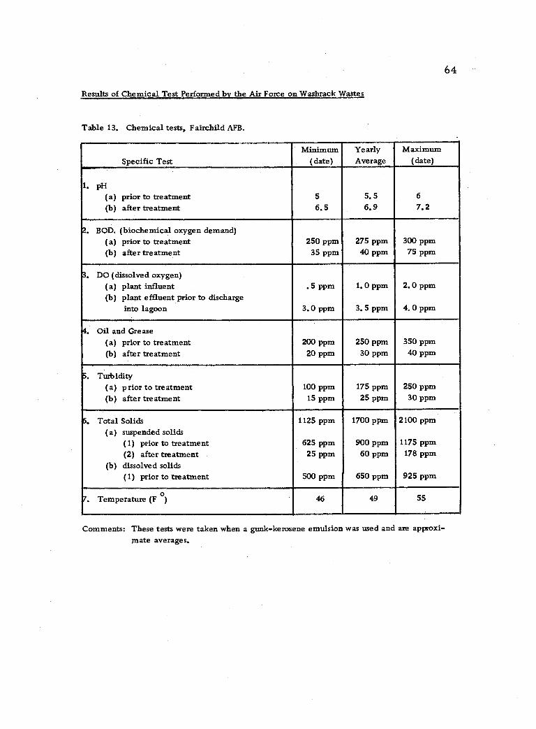
64
Results of Chemical Test Performed by the Air Force on Washrack Wastes
Table 13. Chemical tests, Fairchild AFB.
Specific Test Minimum
(date) Yearly Average
Maximum (date)
1. pH (a) prior to treatment (b) after treatment
5
6.5 5.5 6.9
6
7.2
2. BOD. (biochemical oxygen demand) (a) prior to treatment (b) after treatment
250 ppm 35 ppm
275 ppm 40 ppm
300 ppm 75 ppm
3. DO (dissolved oxygen) (a) plant influent (b) plant effluent prior to discharge
into lagoon
.5 ppm
3.0 ppm
1.0 ppm
3. S ppm
2.0 ppm
4.0 ppm
4. Oil and Grease (a) prior to treatment (b) after treatment
200 ppm 20 ppm
250 ppm 30 ppm
350 ppm 40 ppm
5. Turbidity (a) prior to treatment (b) after treatment
100 ppm 15 ppm
175 ppm 25 ppm
250 ppm 30 ppm
6. Total Solids (a) suspended solids
(1) prior to treatment (2) after treatment
(b) dissolved solids (1) prior to treatment
1125 ppm
625 ppm 25 ppm
500 ppm
1700 ppm
900 ppm 60 ppm
650 ppm
2100 ppm
1175 ppm 178 ppm
925 ppm
7. Temperature (F o) 46 49 55
Comments: These tests were taken when a gunk- kerosene emulsion was used and are approxi- mate averages.
r
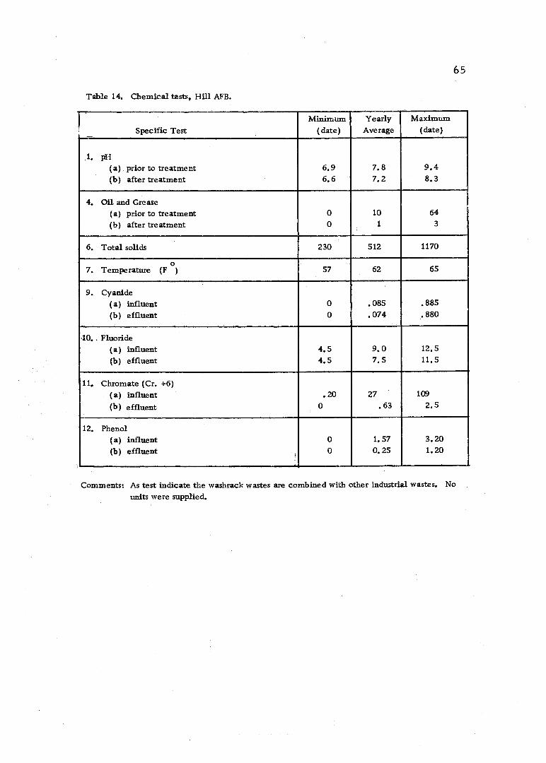
65
Table 14. Chemical tests, Hill AFB.
Specific Test Minimum
(date) Yearly
Average Maximum
(date)
1. pH
(a) prior to treatment 6.9 7.8 9.4 (b) after treatment 6.6 7.2 8.3
4. Oil and Grease (a) prior to treatment 0 10 64
(b) after treatment 0 1 3
6. Total solids 230 512 1170
f o 7. Temperature (F ) 57 62 65
9. Cyanide (a) influent 0 .085 .885 (b) effluent 0 .074 .880
40.. Fluoride (a) influent 4.5 9.0 12.5 (b) effluent 4.5 7.5 11.5
11. Chromate (Cr. +6) (a) influent .20 27 109
(b) effluent 0 .63 2.5
12. Phenol (a) influent 0 1.57 3.20 (b) effluent 0 0.25 1.20
Comments: As test indicate the washrack wastes are combined with other industrial wastes. No
units were supplied.
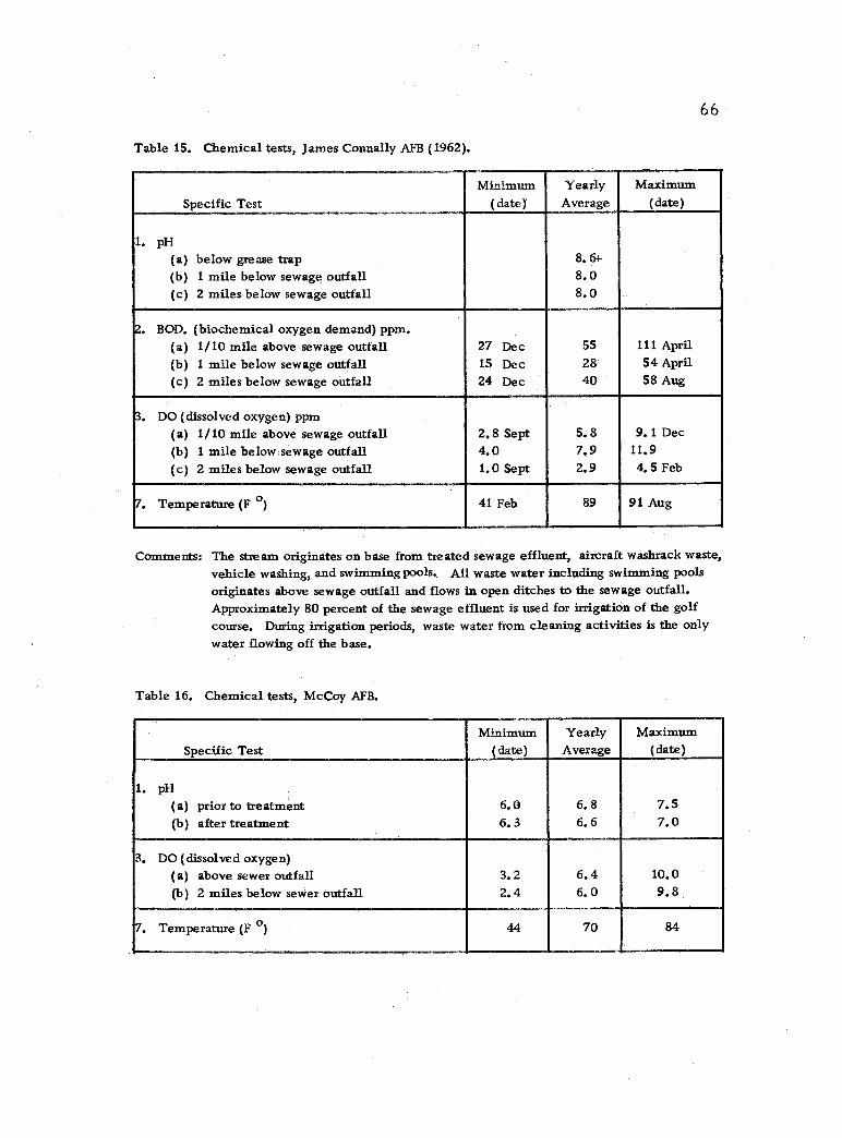
66
Table 15. Chemical tests, James Connally AFB (1962).
Specific Test Minimum
(date) Yearly
Average Maximum
(date)
1. pH
(a) below grease trap 8.6+ (b) 1 mile below sewage outfall 8.0 (c) 2 miles below sewage outfall 8.0
2. BOD. (biochemical oxygen demand) ppm. (a) 1/10 mile above sewage outfall 27 Dec 55 111 April (b) 1 mile below sewage outfall 15 Dec 28 54 April (c) 2 miles below sewage outfall 24 Dec 40 58 Aug
3. DO (dissolved oxygen) ppm (a) 1 /10 mile above sewage outfall 2.8 Sept 5.8 9.1 Dec (b) 1 mile below sewage outfall 4.0 7.9 11.9 (c) 2 miles below sewage outfall 1.0 Sept 2.9 4.5 Feb
7. Temperature (F 0) 41 Feb 89 91 Aug
Comments: The stream originates on base from treated sewage effluent, aircraft washrack waste, vehicle washing, and swimming pools, All waste water including swimming pools originates above sewage outfall and flows in open ditches to the sewage outfall. Approximately 80 percent of the sewage effluent is used for irrigation of the golf course. During irrigation periods, waste water from cleaning activities is the only water flowing off the base.
Table 16. Chemical tests, McCoy AFB.
Specific Test Minimum
(date) Yearly Average
Maximum (date)
1. pH
(a) prior to treatment 6.0 6.8 7.5 (b) after treatment 6.3 6.6 7.0
3. DO (dissolved oxygen) (a) above sewer outfall 3.2 6.4 10.0 (b) 2 miles below sewer outfall 2.4 6.0 9.8
7. Temperature (F 0) 70 84 44
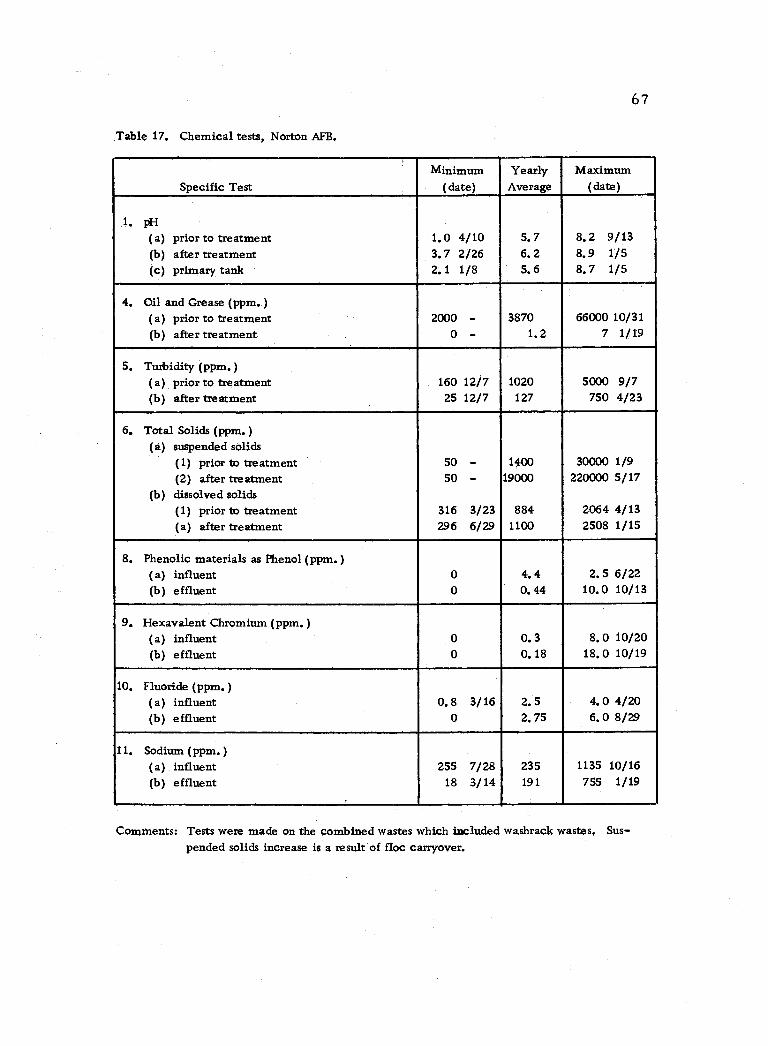
67
Table 17. Chemical tests, Norton AFB.
Specific Test Minimum
(date) Yearly Average
Maximum (date)
1. pH
(a) prior to treatment 1.0 4/10 5.7 8.2 9/13 (b) after treatment 3.7 2/26 6.2 8.9 1/5 (c) primary tank 2.1 1/8 5.6 8.7 1/5
4. Oil and Grease (ppm. ) (a) prior to treatment 2000 - 3870 66000 10/31 (b) after treatment 0 - 1.2 7 1/19
5. Turbidity (ppm. )
(a) prior to treatment 160 12/7 1020 5000 9/7 (b) after treatment 25 12/7 127 750 4/23
6. Total Solids (ppm.) (a) suspended solids
(1) prior to treatment 50 - 1400 30000 1/9 (2) after treatment 50 - 19000 220000 5/17
(b) dissolved solids (1) prior to treatment 316 3/23 884 2064 4/13 (a) after treatment 296 6/29 1100 2508 1/15
8. Phenolic materials as Phenol (ppm. )
(a) influent 0 4.4 2.5 6/22 (b) effluent 0 0.44 10.0 10/13
9. Hexavalent Chromium (ppm. )
(a) influent 0 0.3 8.0 10/20 (b) effluent 0 0.18 18.0 10/19
10. Fluoride (ppm. )
(a) influent 0.8 3/16 2.5 4.0 4/20 (b) effluent 0 2.75 6.0 8/29
11. Sodium (ppm.) (a) influent 255 7/28 235 1135 10/16 (b) effluent 18 3/14 191 755 1/19
Comments: Tests were made on the combined wastes which included washrack wastes. Sus- pended solids increase is a result of floc carryover.
-
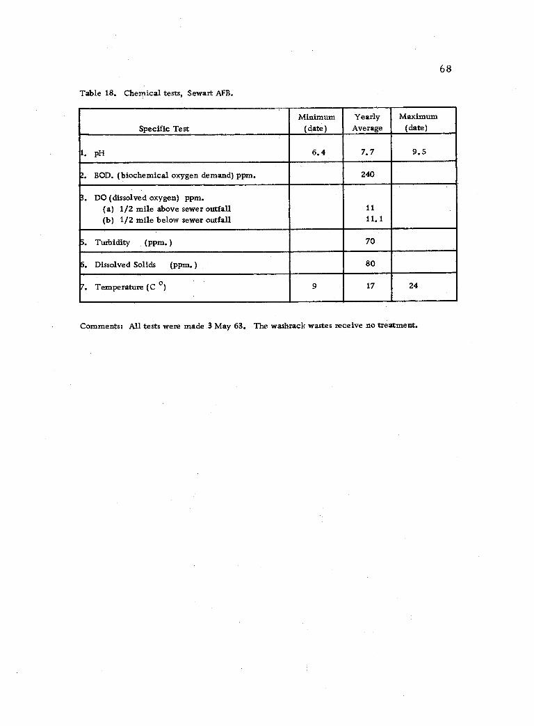
68
Table 18. Chemical tests, Sewart AFB.
Specific Test Minimum
(date) Yearly Average
Maximum (date)
1. pH 6.4 7.7 9.5
2. BOD. (biochemical oxygen demand) ppm. 240
3. DO (dissolved oxygen) ppm. (a) 1/2 mile above sewer outfall 11
(b) 1/2 mile below sewer outfall 11. 1
5. Turbidity (ppm.) 70
6. Dissolved Solids (ppm.) 80
7. Temperature (C 0) 9 17 24
Comments: All tests were made 3 May 63. The washrack wastes receive no treatment.
f -
-
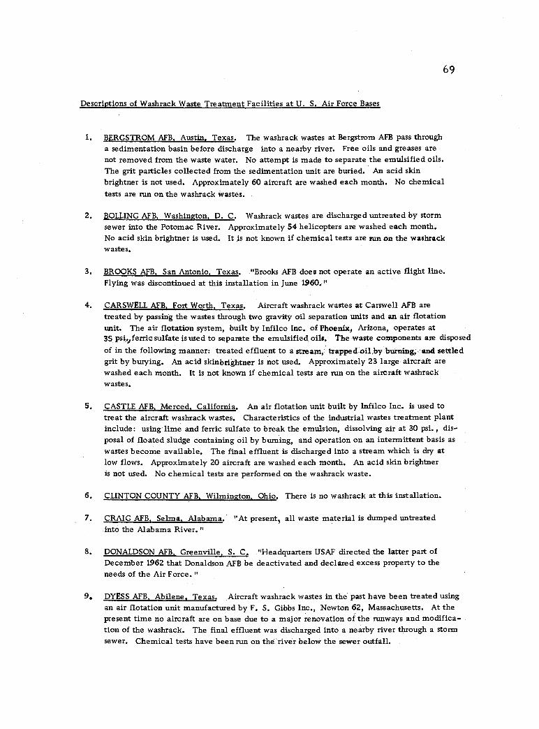
69
Descriptions of Washrack Waste Treatment Facilities at U. S. Air Force Bases
1. BERGSTROM AFB, Austin, Texas. The washrack wastes at Bergstrom AFB pass through a sedimentation basin before discharge into a nearby river. Free oils and greases are not removed from the waste water. No attempt is made to separate the emulsified oils. The grit particles collected from the sedimentation unit are buried. An acid skin brightner is not used. Approximately 60 aircraft are washed each month. No chemical tests are run on the washrack wastes.
2. BOLLING AFB, Washington. D. C. Washrack wastes are discharged untreated by storm sewer into the Potomac River. Approximately 54 helicopters are washed each month. No acid skin brightner is used. It is not known if chemical tests are run on the washrack wastes.
3. BROOKS AFB, San Antonio, Texas. "Brooks AFB does not operate an active flight line. Flying was discontinued at this installation in June 1960."
4, CARSWELL AFB, Fort Worth, Texas. Aircraft washrack wastes at Carswell AFB are treated by passing the wastes through two gravity oil separation units and an air flotation unit. The air flotation system, built by Infilco Inc. of Phoenix, Arizona, operates at 35 psivferric sulfate is used to separate the emulsified oils. The waste components are disposed of in the following manner: treated effluent to a stream, trapped oil,by burning, and settled grit by burying. An acid skinbrightner is not used. Approximately 23 large aircraft are washed each month. It is not known if chemical tests are run on the aircraft washrack wastes.
5. CASTLE AFB. Merced, California. An air flotation unit built by Infilco Inc. is used to treat the aircraft washrack wastes. Characteristics of the industrial wastes treatment plant include: using lime and ferric sulfate to break the emulsion, dissolving air at 30 psi. , dis- posal of floated sludge containing oil by burning, and operation on an intermittent basis as
wastes become available. The final effluent is discharged into a stream which is dry at low flows. Approximately 20 aircraft are washed each month. An acid skin brightner is not used. No chemical tests are performed on the washrack waste.
6, CLINTON COUNTY AFB, Wilmington. Ohio. There is no washrack at this installation.
7. CRAIG AFB, Selma, Alabama. "At present, all waste material is dumped untreated into the Alabama River."
8. DONALDSON AFB, Greenville, S. C. "Headquarters USAF directed the latter part of December 1962 that Donaldson AFB be deactivated and declared excess property to the needs of the Air Force. "
9. DYESS AFB, Abilene, Texas. Aircraft washrack wastes in the past have been treated using an air flotation unit manufactured by F. S. Gibbs Inc., Newton 62, Massachusetts. At the present time no aircraft are on base due to a major renovation of the runways and modifica- tion of the washrack. The final effluent was discharged into a nearby river through a storm sewer, Chemical tests have been run on the river below the sewer outfall,
-
-
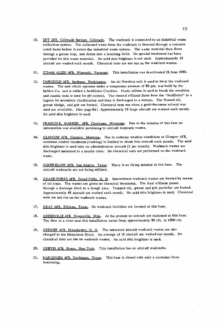
70
10. ENT AFB, Colorado Springs, Colorado. The washrack is connected to an industrial waste collection system. The collected waste from the washrack is directed through a concrete catch basin before it enters the industrial waste system. The waste material then flows
through a grease trap, and drains into a leaching field. No special treatment has been provided for this waste material. An acid skin brightner is not used. Approximately 15
aircraft are washed each month. Chemical tests are not run on the washrack wastes.
11. ETHAN ALLEN AFB, Winooski, Vermont. This installation was deactivated 25 June 1960.
12. FAIRCHILD AFB, Spokane, Washington. An air flotation unit is used to treat the washrack wastes. The unit which operates under a compressor pressure of 50 psi. was built by the
Infilco Co. and is called a Sediflotor Clarifier. Ferric sulfate is used to break the emulsion and caustic soda is used for pH control. The treated effluent flows from the "Sediflotor" to a lagoon for secondary clarification and then is discharged to a stream. The floated oil, grease sludge, and grit are buried. Chemical tests run when a gunk- kerosene solvent was
used are available. (See page 64 ) Approximately 18 large aircraft are washed each month. An acid skin brightner is used.
13. FRANCIS E. WARREN, AFB, Cheyenne. Wyoming. Due to the mission of this base no
information was available pertaining to aircraft washrack wastes.
14. GLASGOW AFB, Glasgow, Montana. Due to extreme weather conditions at Glasgow AFB,
corrosion control treatment (washing) is limited to about four aircraft each month. The acid skin brightner is used only on administrative aircraft (2 per month). Washrack wastes are
discharged untreated to a nearby river. No chemical tests are performed on the washrack
waste.
15. GOODFELLOW AFB, San Angelo, Texas. There is no flying mission at this base. The aircraft washracks are not being utilized.
16. GRAND FORKS AFB, Grand Forks, N. D. Intermittent washrack wastes are treated by means
of oil traps. The wastes are given no chemical treatment. The final effluent passes
through a drainage ditch to a slough area. Trapped oil, grease and grit particles are buried. Approximately 45 aircraft are washed each month. No acid skin brightner is used. Chemical tests are not run on the washrack wastes.
17. GRAY AFB, Killeen. Texas. No washrack facilities are located at this base.
18. GREENVILLE AFB, Greenville, Miss. At the present no aircraft are stationed at this base. The flow in a river near this installation varies from approximately 50 cfs. to 1500 cfs.
19. GRENIER AFB, Manchester, N. H. The untreated aircraft washrack wastes are dis- charged to the Mennimac River. An average of 18 aircraft are washed per month. No
chemical tests are run on washrack wastes. An acid skin brightner is used.
20. GRIFFIS AFB, Rome, New York. This installation has no aircraft washracks.
21. HARLINGEN AFB, Harlingen, Texas. This base is closed with only a caretaker force
remaining.
-
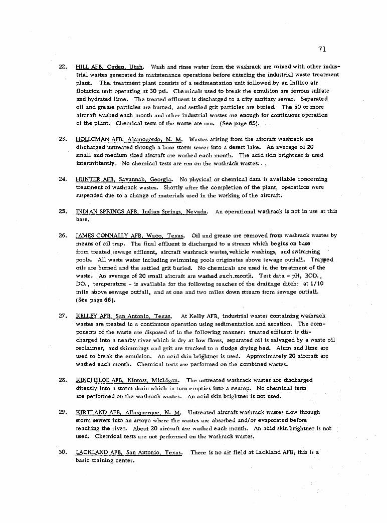
71
22. HILL AFB, Ogden. Utah. Wash and rinse water from the washrack are mixed with other indus- trial wastes generated in maintenance operations before entering the industrial waste treatment plant. The treatment plant consists of a sedimentation unit followed by an Infilco air flotation unit operating at 30 psi. Chemicals used to break the emulsion are ferrous sulfate and hydrated lime. The treated effluent is discharged to a city sanitary sewer, Separated oil and grease particles are burned, and settled grit particles are buried. The 50 or more aircraft washed each month and other industrial wastes are enough for continuous operation of the plant. Chemical tests of the waste are run, (See page 65).
23. HOLLOMAN AFB, Alamogordo, N. M. Wastes arising from the aircraft washrack are discharged untreated through a base storm sewer into a desert lake. An average of 20
small and medium sized aircraft are washed each month. The acid skin brightner is used intermittently. No chemical tests are run on the washrack wastes.
24. HUNTER AFB, Savannah, Georgia. No physical or chemical data is available concerning treatment of washrack wastes. Shortly after the completion of the plant, operations were suspended due to a change of materials used in the working of the aircraft.
25. INDIAN SPRINGS AFB, Indian Springs, Nevada. An operational washrack is not in use at this base.
26. JAMES CONNALLY AFB, Waco, Texas. Oil and grease are removed from washrack wastes by means of oil trap. The final effluent is discharged to a stream which begins on base from treated sewage effluent, aircraft washrack wastes, vehicle washings, and swimming pools. All waste water including swimming pools originates above sewage outfall. Trapped oils are burned and the settled grit buried. No chemicals are used in the treatment of the waste. An average of 20 small aircraft are washed each.montji. Test data - pH, BOD., DO., temperature - is available for the following reaches of the drainage ditch: at 1/10 mile above sewage outfall, and at one and two miles down stream from sewage outfall. (See page 66).
27. KELLEY AFB, San Antonio, Texas. At Kelly AFB, industrial wastes containing washrack wastes are treated in a continuous operation using sedimentation and aeration. The com- ponents of the waste are disposed of in the following manner: treated effluent is dis- charged into a nearby river which is dry at low flows, separated oil is salvaged by a waste oil reclaimer, and skimmings and grit are trucked to a sludge drying bed. Alum and lime are used to break the emulsion. An acid skin brightner is used. Approximately 20 aircraft are washed each month. Chemical tests are performed on the combined wastes.
28. KINCHELOE AFB, Kinross, Michigan. The untreated washrack wastes are discharged directly into a storm drain which in turn empties into a swamp. No chemical tests are performed on the washrack wastes. An acid skin brightner is not used.
29. KIRTLAND AFB, Albuquerque, N. M. Untreated aircraft washrack wastes flow through storm sewers into an arroyo where the wastes are absorbed and /or evaporated before reaching the river. About 20 aircraft are washed each month. An acid skin brightner is not used. Chemical tests are not performed on the washrack wastes.
30. LACKLAND AFB, San Antonio. Texas. There is no air field at Lackland AFB; this is a
basic training center.
.
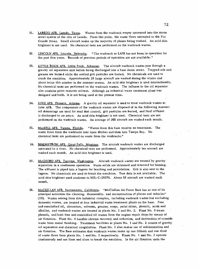
72
31.. LAREDO AFB, Laredo, Texas. Wastes from the washrack empty untreated into the storm sewer system of the city of Laredo. From this point, the waste flows untreated to the Rio Grande River. Small aircraft make up the majority of planes being washed. An acid skin brightner is not used. No chemical tests are performed on the washrack wastes.
32. LINCOLN AFB, Lincoln, Nebraska. "The washrack at LAFB has not been in operation for
the past five years. Records of previous periods of operation are not available."
33. LITTLE ROCK AFB, Little Rock, Arkansas. The aircraft washrack wastes pass through a
gravity oil separation unit before being discharged into a base storm sewer. Trapped oils and greases are burned while the settled grit particles are buried. No chemicals are used to crack the emulsion. Approximately 25 large aircraft are washed during the winter and about twice this number in the summer season. An acid skin brightner is used intermittently. No chemical tests are performed on the washrack wastes. The influent to the oil separator also contains paint remover solvent. Although an industrial waste treatment plant was designed and built, it is not being used at the present time.
34. LUKE AFB, Phoenix, Arizona. A gravity oil separator is used to treat washrack wastes at Luke AFB. The components of the washrack wastes are disposed of in the following manner: oil skimmings are used for road dust control, grit particles are buried, and final effluent is discharged to an aroyo. An acid skin brightner is not used. Chemical tests are not performed on the washrack wastes. An average of 200 aircraft are washed each month.
35. MacDILL AFB, Tampa, Florida. "Wastes from this base receive no treatment. The waste flows from the washracks into open ditches and then into Tampa Bay, No chemical tests are performed on waste from the washracks,"
36. MALMSTROM AFB, Great Falls, Montana. The aircraft washrack wastes are discharged untreated to a river. No chemical tests are performed. Approximately ten aircraft are washed each month. An acid skin brightner is used.
37. McCHORD AFB, Tacoma, Washington. Aircraft washrack wastes are treated by gravity separation in a continuous operation. Waste solids are skimmed and removed for burning. The effluent is piped into a lagoon for leaching and percolation. Grit is also sent to the lagoon. No chemicals are used to break the emulsion. Test data is not available. The acid skin brightner used conforms to MIL -C- 25378. About 32 aircraft are washed each month.
38. McCLELLAN AFB, Sacramento, California. "McClellan Air Force Base has as one of its principal activities the cleaning. disassembly. and reconstruction of planes and vehicles" (23). Wastes arising from this industrial complex, including washrack wastes but excluding domestic wastes, are treated at four industrial waste treatment plants on the base. Free and emulsified oil, chromium, solvents, greases, soaps, paint skims, phenols, acids and alkalies, and washrack wastes are treated in plants No. 1 and No. 2. Plant No. 3 treats phenols, and both free and emulsified oil wastes from the engine repair shops by means of
air flotation. Plant No. 4 handles chrome recovery and reduction, and destruction of cyanide waste from metal finishing. Treatment facilities at plants No. 1 and No. 2 consist of gravity oil separation and chemical coagulation. Plant No. 1 also makes use of sedimentation and air flotation. The Base estimates that washrack wastes make up one fiftieth and one third of waste flows from plants No. 1 and No. 2 respectively. Plants No. 1 and No. 2 operate continuously and use lime and alum to break the emulsion. In the air flotation units the
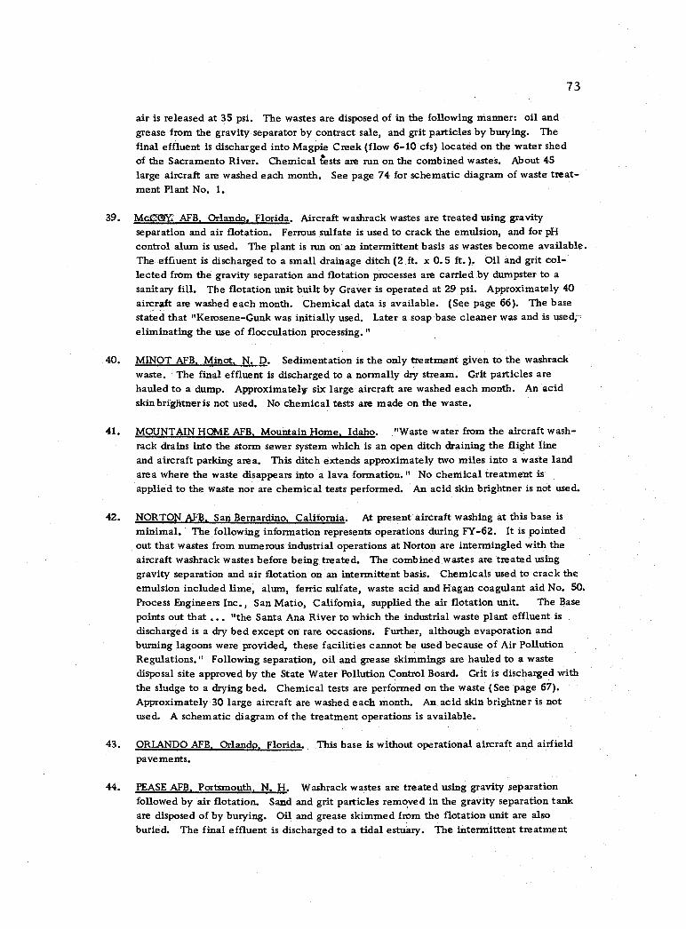
73
air is released at 35 psi. The wastes are disposed of in the following manner: oil and grease from the gravity separator by contract sale, and grit particles by burying, The final effluent is discharged into Magpie Creek (flow 6 -10 cfs) located on the water shed of the Sacramento River. Chemical tests are run on the combined wastes. About 45
large aircraft are washed each month. See page 74 for schematic diagram of waste treat- ment Plant No. 1.
39. McCYY AFB, Orlando, Florida. Aircraft washrack wastes are treated using gravity separation and air flotation. Ferrous sulfate is used to crack the emulsion, and for pH
control alum is used. The plant is run on an intermittent basis as wastes become available. The effluent is discharged to a small drainage ditch (2 ft. x 0.5 ft. ). Oil and grit col- lected from the gravity separation and flotation processes are carried by dumpster to a
sanitary fill. The flotation unit built by Graver is operated at 29 psi. Approximately 40
aircraft are washed each month. Chemical data is available. (See page 66). The base stated that "Kerosene -Gunk was initially used. Later a soap base cleaner was and is used, eliminating the use of flocculation processing."
40. MINOT AFB, Minot, N. D. Sedimentation is the only treatment given to the washrack waste. The final effluent is discharged to a normally dry stream. Grit particles are hauled to a dump. Approximately six large aircraft are washed each month. An acid skinbrightneris not used. No chemical tests are made on the waste.
41. MOUNTAIN HOME AFB, Mountain Home, Idaho. "Waste water from the aircraft wash- rack drains into the storm sewer system which is an open ditch draining the flight line and aircraft parking area. This ditch extends approximately two miles into a waste land area where the waste disappears into a lava formation." No chemical treatment is
applied to the waste nor are chemical tests performed. An acid skin brightner is not used.
42. NORTON AFB, San Bernardino, California. At present aircraft washing at this base is
minimal. The following information represents operations during FY -62. It is pointed out that wastes from numerous industrial operations at Norton are intermingled with the aircraft washrack wastes before being treated. The combined wastes are treated using gravity separation and air flotation on an intermittent basis. Chemicals used to crack the emulsion included lime, alum, ferric sulfate, waste acid and Hagan coagulant aid No. 50. Process Engineers Inc., San Matio, California, supplied the air flotation unit. The Base
points out that ... "the Santa Ana River to which the industrial waste plant effluent is
discharged is a dry bed except on rare occasions. Further, although evaporation and burning lagoons were provided, these facilities cannot be used because of Air Pollution Regulations." Following separation, oil and grease skimmings are hauled to a waste disposal site approved by the State Water Pollution Control Board. Grit is discharged with the sludge to a drying bed. Chemical tests are performed on the waste (See page 67). Approximately 30 large aircraft are washed each month. An acid skin brightner is not used. A schematic diagram of the treatment operations is available.
43. ORLANDO AFB, Orlando, Florida. This base is without operational aircraft and airfield pavements.
44. PEASE AFB, Portsmouth, N. H. Washrack wastes are treated using gravity separation followed by air flotation. Sand and grit particles removed in the gravity separation tank are disposed of by burying. Oil and grease skimmed from the flotation unit are also buried. The final effluent is discharged to a tidal estuary. The intermittent treatment
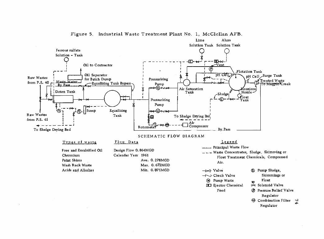
Raw Wastes I
from P.S. 40 r
Doten Tank
Figure
Ferrous sulfate Solution - Tank
Q
5. Industrial Waste Treatment Plant No. 1, McClellan AFB. Lime Alum
Solution Tank Solution Tank
Oil to Contractor
Oil Separator for Batch Dump
Equalizing Tank Bypass
Y - - - ---- -- --T - r--co-'
1 1 nt
Pressurizing Pump
Flotation Tank pH Cell .Surge Tank
Treated Waste reek
pH Ce
in4 .
Air Saturation Tank
Raw Wastes from P.S. 41
I®
.4-- __ - -1_ -1 To Sludge Drying Bed
0.1 _ 7um - 1
i
Types of waste
Equalizing Tank
Flow Data
Sludge, r---©---D4--
To Sludge Drying Bed' - -- - - - -
Air Compressor Roto etdf ® -
SCHEMATIC FLOW DIAGRAM
Free and Emulsified Oil Design Flow 0.864MGD Chromium Calendar Year 1961
Paint Skims Ave. 0. 278MGD Wash Rack Waste Max. 0. 672MGD
Acids and Alkalies Min. 0.071MGD
By__Pass
ennison Nozzle boat
Tank
Legend Principal Waste Flow
- - - Waste Concentrates, Sludge, Skimming or Float Treatment Chemicals, Compressed Air.
-po- Valve -N Check Valve
Q Pump Waste ED Ejector Chemical
Feed
Q Pump Sludge, Skimmings or
rr Float b1d Solenoid Valve ® Pressure Relief Valve
Regulator e Combination Filter
Regulator
r-- d
a
i
-
-
io
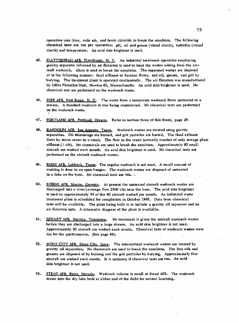
75
operation uses lime, soda ash, and ferric chloride to break the emulsion. The following chemical tests are run per operation: pH, oil and grease (visual check), turbidity (visual check) and temperature. An acid skin brightner is used.
45. PLATTSBURGH AFB, Plattsburgh. N. Y. An industrial treatment operation employing gravity separator followed by air flotation is used to treat the wastes arising from the air- craft washrack. Alum is used to break the emulsion. The separated wastes are disposed of in the following manner: final effluent to Saranac River, and oil, grease, and grit by burying. The treatment plant is operated continuously. The air flotation was manufactured by Gibbs Flotation Unit, Newton 62, Massachusetts. An acid skin brightner is used. No chemical test are performed on the washrack waste.
POPE AFB, Fort Bragg. N. C. The waste from a temporary washrack flows untreated to a
stream. A standard washrack is now being constructed. No chemical tests are performed on the washrack waste.
47. PORTLAND AFB, Portland, Oregon. Refer to section three of this thesis, page 29.
48. RANDOLPH AFB, San Antonio. Texas. Washrack wastes are treated using gravity separation. Oil skimmings are burned, and grit particles are buried. The final effluent flows by storm sewer to a creek. The flow in the creek normally consists of only sewage plant effluent (1 cfs). No chemicals are used to break the emulsion. Approximately 60 small aircraft are washed each month. An acid skin brightner is used. No chemical tests are performed on the aircraft washrack wastes.
49. REESE AFIf. Lubbock, Texas. The regular washrack is not used. A small amount of washing is done in an open hanger. The washrack wastes are disposed of untreated in a lake on the base. No chemical tests are run.;.,
50. ROBINS AFB, Macon, Georgia. At present the untreated aircraft washrack wastes are discharged into a river (average flow 2800 cfs) near the base. The acid skin brightner is used on approximately 30 of the 40 aircraft washed per month. An industrial waste treatment plant is scheduled for completion in October 1963. Data from chemical tests will be available. The plant being built is to include a gravity oil separator and an air flotation unit. A schematic diagram of the plant is available.
51. SEWART AFB, Smyrna, Tennessee. No treatment is given the aircraft washrack wastes before they are discharged into a large stream. An acid skin brightner is not used. Approximately 30 aircraft are washed each month. Chemical tests of washrack wastes were run for the questionnaire. (See page 68).
52. SIOUX CITY AFB, Sioux City, Iowa. The intermittent washrack wastes are treated by gravity oil separation. No chemicals are used to break the emulsion. The free oils and greases are disposed of by burning and the grit particles by burying. Approximately five aircraft are washed each month. It is unknown if chemical tests are run.. An acid skin brightner is not used.
53, STEAD AFB, Reno, Nevada. Washrack volume is small at Stead AFB. The washrack drains into the dry lake beds at either end of the field for natural leaching.
46.
76
54. STEWART AFB, Newburgh, N. Y. "Stewart AFB does not have any industrial waste treatment of the washrack wastes. The washrack wastes empty directly into a nearby surface stream."
SS. SUFFOLK COUNTY AFB, Westhampton Beach, New York. There is no washrack at this installation.
56. TINKER AFB, Oklahoma City, Oklahoma. At present the untreated washrack wastes from approximately 25 aircraft washings per month are discharged directly to a stream (3.0 cfs to 6.6 cfs). No chemical tests are being performed. An acid skin brightner is used.
According to TAFB... "An industrial waste plant is now being constructed here and will be completed some time in October 1963. This plant will be used to treat all industrial wastes originating on Tinker Air Force Base including the wastes from aircraft washracks. The plant will consist of an air flotation unit with the addition of flocculation chemicals, ferrous sulfate and lime, to remove oils, greases, chromatic wastes, and other metallic substances. The effluent will then be processed through the existing sewage treatment plant which is a biological trickling filter type. The biological filtration will be used to remove phenolic wastes containing a mixture of ortho, meta, and para cresols which will be a result of aircraft washing and engine cleaning operations. Pilot plant studies here indicated that the bacteria on a trickling filter could withstand concentrations of 100 ppm. of phenols and that 80 percent removal could be effected at this concentration. If the concentrations of phenols exceeds 100 ppm., it is proposed to add a commercial fertilizer to the trickling filter at the rate of .025 percent per 1000 ppm. concentration of phenol or 25 percent of the phenolic concentration. The grit, oils, chromates, and other sludge removed from the air flotation unit will be dried and dis- posed of on land fills."
57, TURNER AFB, Albany, Georgia. The washrack wastes from this base are discharged un- treated to a river. Approximately ten large aircraft are washed each month. An acid skin brightner is used. No chemical tests are performed on the washrack wastes.
58. TYNDALL AFB, Panama City, Florida. No treatment is given to the washrack wastes at this base. Chemical tests on the waste are not performed.
59. VANCE AFB, Enid, Oklahoma. Aircraft washrack wastes are not treated at this base.
60. VANDENBERG AFB, Lompoc, California. "Aircraft washing is a very minor item at this base. The average is about one a day; therefore, no analysis or treatment is
made on this waste."
61. WALKER AFB. Roswell, New Mexico. "Drainage from the washrack is passed through a gravity type P. C. concrete grease trap and then to the storm sewer system from which it emerges into open drainage ditches and eventually into an on -base evaporation pond." The trapped oils and greases are burned and sediment is buried. No chemicals are used to break the emulsion. Wastes flows are intermittent. A priority demand for water is experienced during the summer months due to shortages. On the average. 40 aircraft are washed each month. An acid skin brightner is used. No chemical tests are performed on the washrack water.
77
62. WEBB AFB, Big Spring, Texas. The aircraft washrack wastes are discharged directly to evaporation pits with no other treatment being given to the waste. Chemical tests are not performed. Approximately 35 small aircraft are washed each month. An acid skin brightner is not used.
63. WENDOVER AFB, Wendover, Utah. "This installation is now in a caretaker status."
64. WHITEMAN AFB, Knob Noster, Mo. Aircraft washrack wastes are treated using air flotation. Treatment is on an intermittent bases as wastes are available. No chemicals are used to break the emulsion. The final effluent is discharged to a stream which is
normally dry. Oil and grease are disposed of using a sand grease trap and the grit particles by a sanitary land fill. No chemical tests are performed at present on the washrack wastes.
65. WILLIAMS AFB, Chandler, Arizona. The aircraft washrack wastes flow untreated to evaporation and leaching beds. No chemical tests are performed. Approximately 42
aircraft are washed each month. Acid skin brightners are used on about five aircraft per month.
66. WRIGHT -PATTERSON AFB, Dayton, Ohio. No information was given concerning the washrack and treatment facilities. However, the statement was made: "An alkaline cleaner is used in the aircraft washracks at this facility which eliminates any require- ment for treatment of wastes."


![Uniform magister studies X * 1st degree studies 2nd degree studies 3rd degree studies postgraduate studies X full-time X part-time C] obligatory ... arrhythmia, pneumonia, asthma](https://img.pdfslide.us/doc/110x75/5f74679c80762429701dd053/-uniform-magister-studies-x-1st-degree-studies-2nd-degree-studies-3rd-degree.jpg)