Embed Size (px)
Citation preview
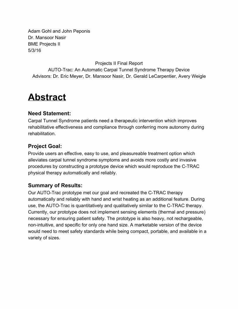
Adam Gohl and John Peponis Dr. Mansoor Nasir BME Projects II 5/3/16
Projects II Final Report AUTOTrac: An Automatic Carpal Tunnel Syndrome Therapy Device
Advisors: Dr. Eric Meyer, Dr. Mansoor Nasir, Dr. Gerald LeCarpentier, Avery Weigle
Abstract Need Statement: Carpal Tunnel Syndrome patients need a therapeutic intervention which improves rehabilitative effectiveness and compliance through conferring more autonomy during rehabilitation. Project Goal: Provide users an effective, easy to use, and pleasureable treatment option which alleviates carpal tunnel syndrome symptoms and avoids more costly and invasive procedures by constructing a prototype device which would reproduce the CTRAC physical therapy automatically and reliably. Summary of Results: Our AUTOTrac prototype met our goal and recreated the CTRAC therapy automatically and reliably with hand and wrist heating as an additional feature. During use, the AUTOTrac is quantitatively and qualitatively similar to the CTRAC therapy. Currently, our prototype does not implement sensing elements (thermal and pressure) necessary for ensuring patient safety. The prototype is also heavy, not rechargeable, nonintuitive, and specific for only one hand size. A marketable version of the device would need to meet safety standards while being compact, portable, and available in a variety of sizes.
Background
Carpal tunnel syndrome is the most prevalent entrapment neuropathy, afflicting approximately 3.7 million Americans each year. The incidence of CTS significantly increases among the older age groups (3044, 4564 years old) as well as among the female population. Carpal tunnel syndrome (CTS) is caused by an impingement of the median nerve in the carpal tunnel, an enclosure of tendons, ligaments, nerves, blood vessels, and connective tissue at the base of the wrist. Clinical manifestations of CTS include numbness, tingling, pain, reduced sensory and motor communication.
Several important changes have been made since senior projects I enabling
successful fabrication and validation of a prototype. Discovery related mechanical traction devices supported the decision for the further development of a carpal tunnel mechanical traction device, specifically the CTRAC. The original focus for projects II was to purchase a CTRAC ourselves, cannibalize the mechanical and pneumatic components, and replace the manual system with an automatic system, using a microcontroller and common electrical components. Utilization of resources such as the LTU fabrication lab and BME department’s PLA filament supply, enabled us to construct a mechanical frame of our own. Additionally, the freedom and versatility of MakerBot 3D printing allowed the frame design to be easily adjusted and reprinted.
Methods Frame: FEA Analysis
After determining the approximate therapeutic force magnitude (75N), our previous FEA model was updated for analysis of the theoretical stresses and displacements.
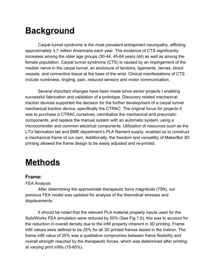
It should be noted that the relevant PLA material property inputs used for the SolidWorks FEA simulation were reduced by 50% (See Fig.1.0), this was to account for the reduction in overall density due to the infill property inherent in 3D printing. Frame infill values were defined to be 25% for all 3D printed frames tested in the Instron. The frame infill value of 25% was a qualitative compromise between frame flexibility and overall strength required by the therapeutic forces, which was determined after printing at varying print infills (1560%).
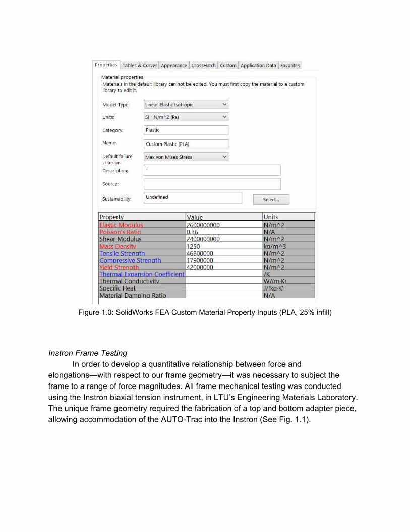
Figure 1.0: SolidWorks FEA Custom Material Property Inputs (PLA, 25% infill)
Instron Frame Testing
In order to develop a quantitative relationship between force and elongations—with respect to our frame geometry—it was necessary to subject the frame to a range of force magnitudes. All frame mechanical testing was conducted using the Instron biaxial tension instrument, in LTU’s Engineering Materials Laboratory. The unique frame geometry required the fabrication of a top and bottom adapter piece, allowing accommodation of the AUTOTrac into the Instron (See Fig. 1.1).
Figure 1.1: SolidWorks Drawing of Top (left) and Bottom (right) Adapter Pieces
We were primarily interested in investigating the differences/similarities between
our 3D printed PLA frames and the CTRAC frame material. Developing a relationship between the two frame materials would allow us to achieve the necessary therapeutic forces (~75N) for the alternative frame material (3D Printed PLA), by tailoring the print infill, geometry, and print configuration variables. One major change following the first round of Instron testing, was the discovered potential benefit of the Vertically Printed Frame (VPF). Benefits included a drastically reduced print mass (See Fig. 1.2) in addition to a potential enhancement of frame stiffness. Stiffness values were calculated by linearly fitting the forceextension curves; the slope of the linear fit curve served as an approximate stiffness for each frame test.
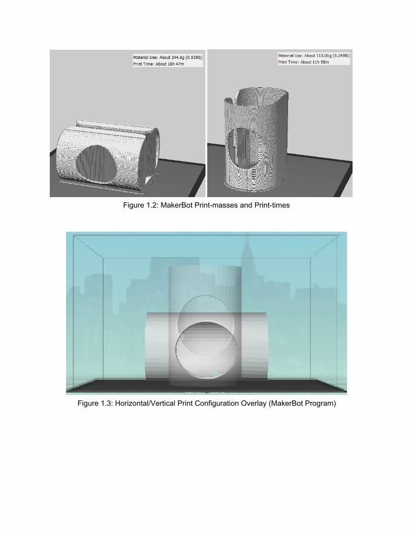
Figure 1.2: MakerBot Printmasses and Printtimes
Figure 1.3: Horizontal/Vertical Print Configuration Overlay (MakerBot Program)
Pump, Valve, and Bladder:
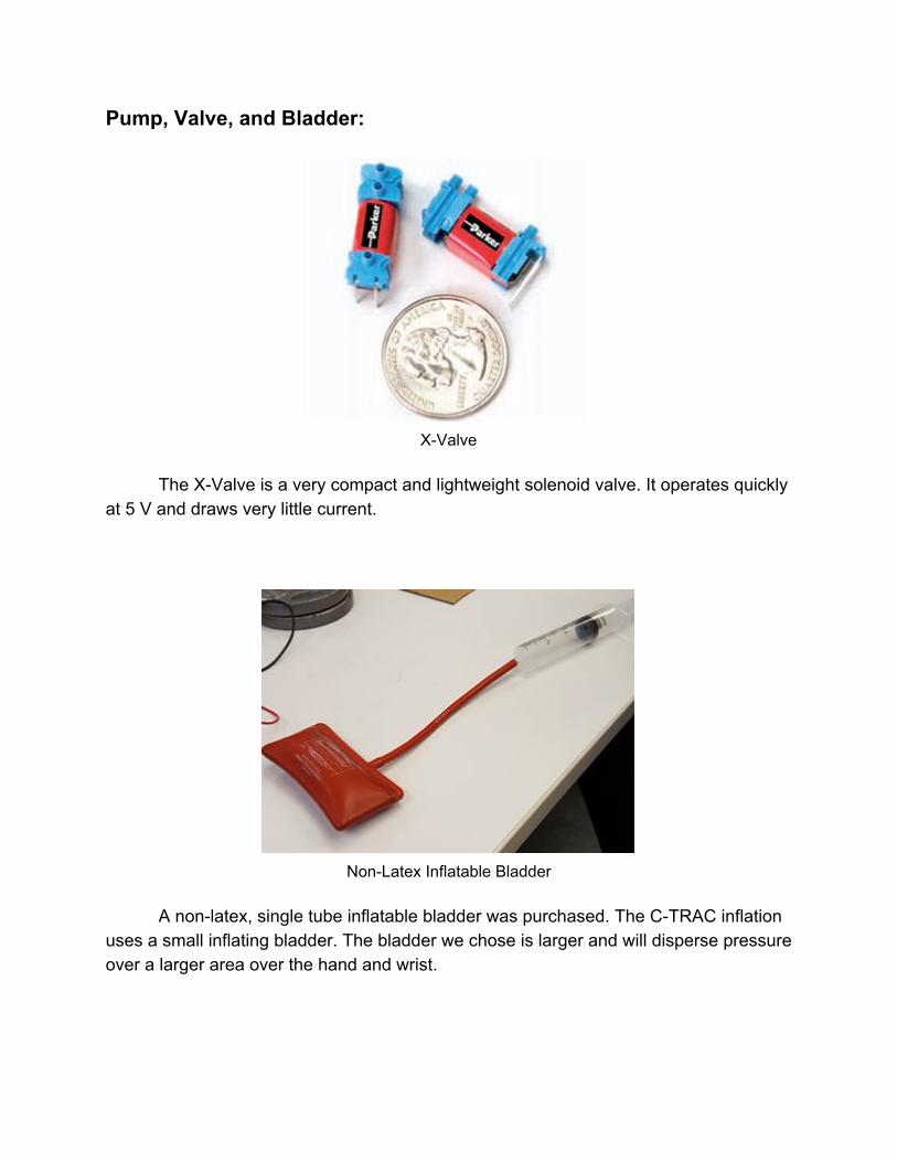
XValve
The XValve is a very compact and lightweight solenoid valve. It operates quickly
at 5 V and draws very little current.
NonLatex Inflatable Bladder
A nonlatex, single tube inflatable bladder was purchased. The CTRAC inflation
uses a small inflating bladder. The bladder we chose is larger and will disperse pressure over a larger area over the hand and wrist.
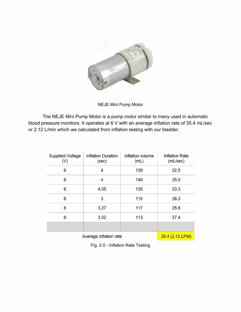
NEJE Mini Pump Motor
The NEJE Mini Pump Motor is a pump motor similar to many used in automatic
blood pressure monitors. It operates at 6 V with an average inflation rate of 35.4 mL/sec or 2.12 L/min which we calculated from inflation testing with our bladder.
Fig. 2.0 Inflation Rate Testing
Heating:
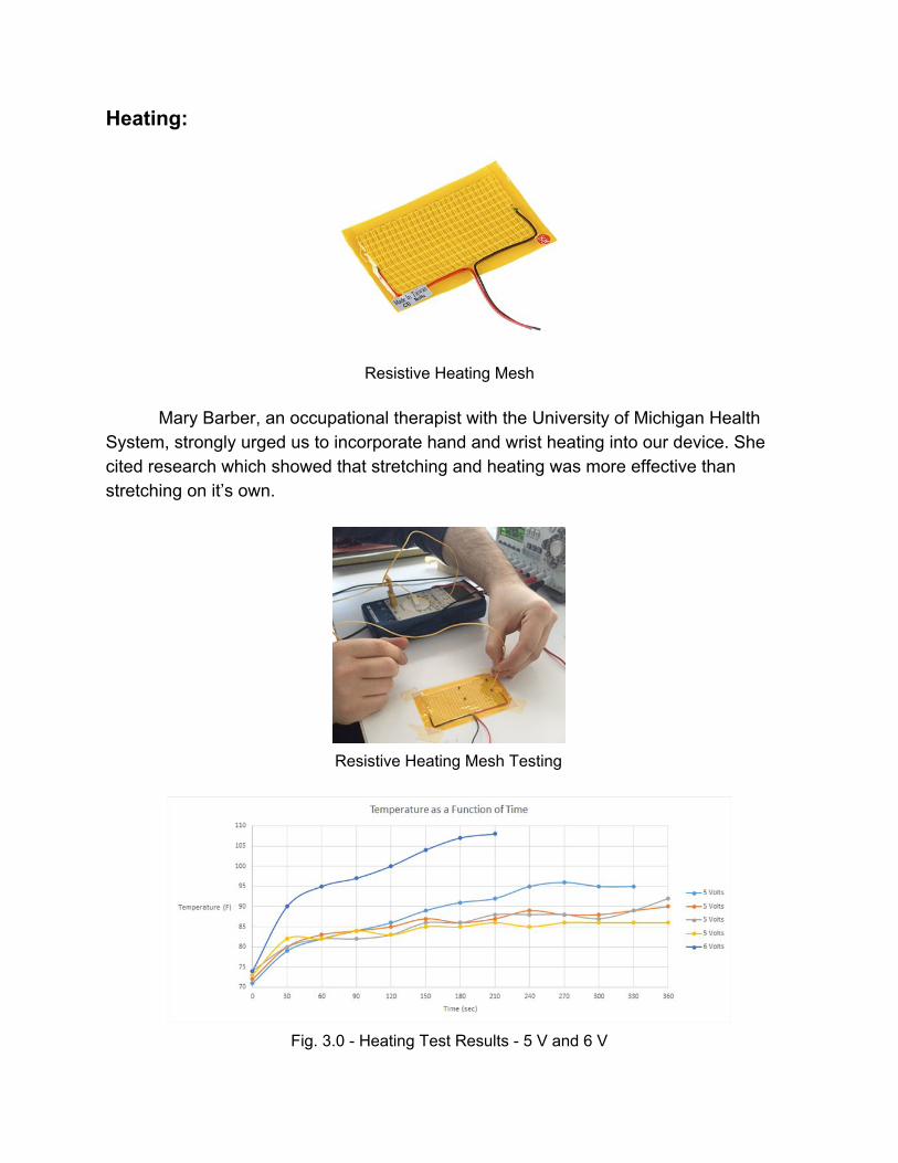
Resistive Heating Mesh
Mary Barber, an occupational therapist with the University of Michigan Health
System, strongly urged us to incorporate hand and wrist heating into our device. She cited research which showed that stretching and heating was more effective than stretching on it’s own.
Resistive Heating Mesh Testing
Fig. 3.0 Heating Test Results 5 V and 6 V
We applied a voltage using a DC power supply to the heating mesh. We
measured the temperature of the mesh using a multimetermeasured thermocouple. The mesh is rated for 5V. We conducted four heating tests at 5 V over five minutes. The mesh did not reach a desired temperature between 115 and 125 degrees Fahrenheit. At 6 V, the mesh reached a temperature of 108 degrees in 3.5 minutes.
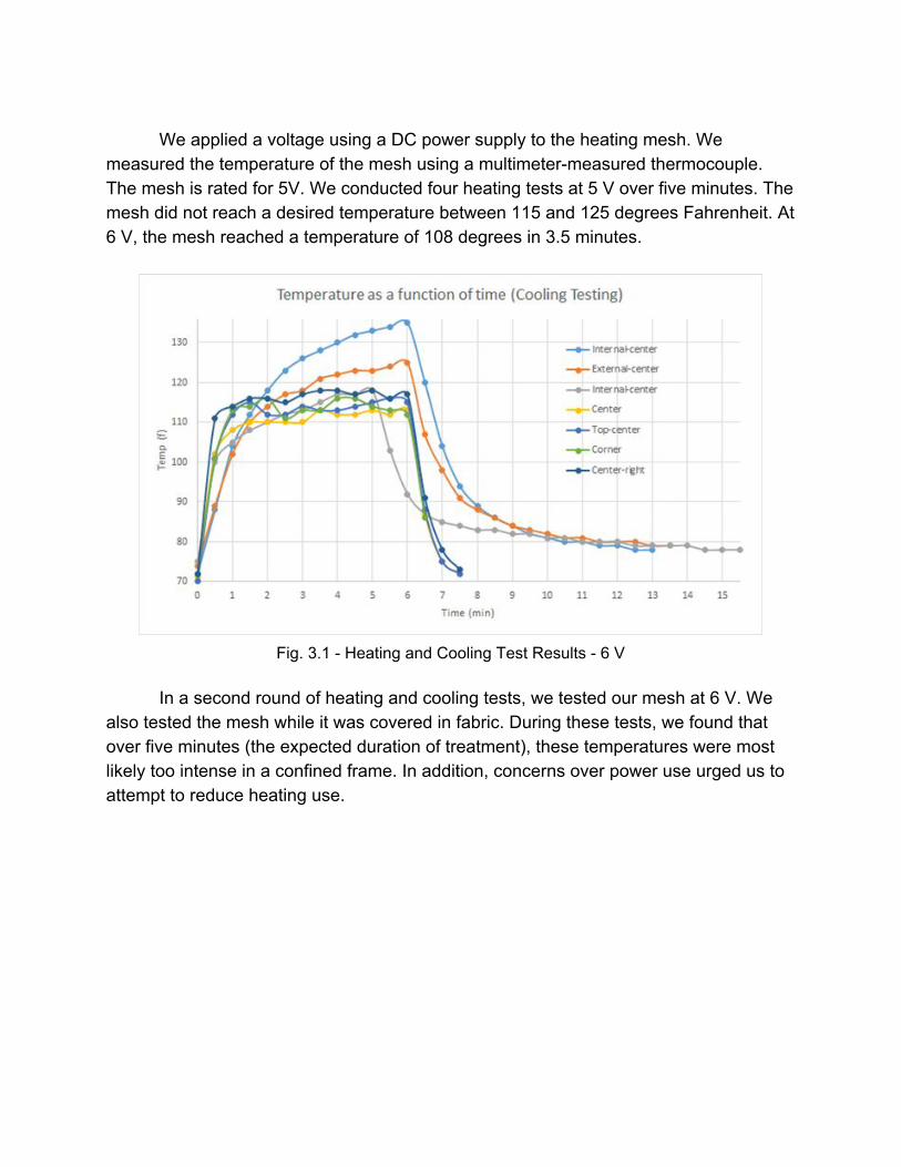
Fig. 3.1 Heating and Cooling Test Results 6 V
In a second round of heating and cooling tests, we tested our mesh at 6 V. We
also tested the mesh while it was covered in fabric. During these tests, we found that over five minutes (the expected duration of treatment), these temperatures were most likely too intense in a confined frame. In addition, concerns over power use urged us to attempt to reduce heating use.
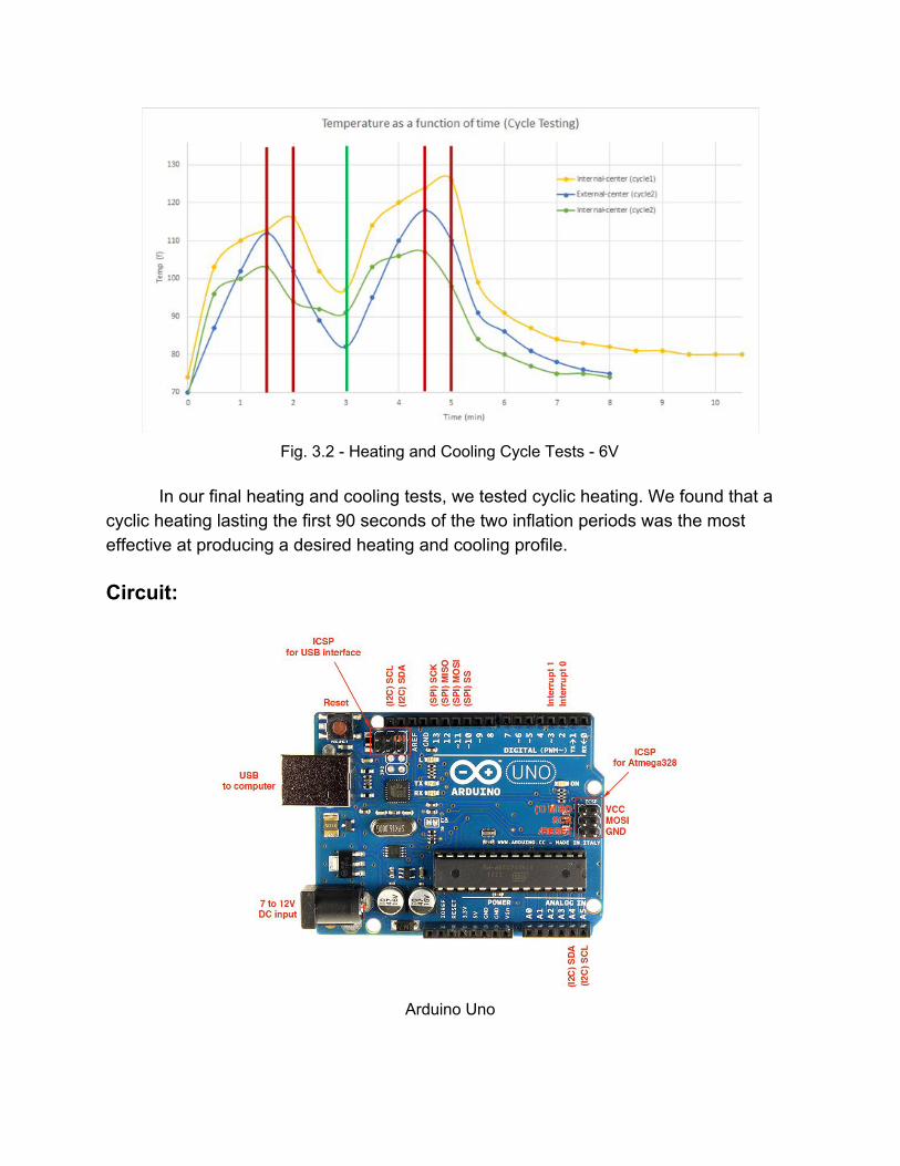
Fig. 3.2 Heating and Cooling Cycle Tests 6V
In our final heating and cooling tests, we tested cyclic heating. We found that a
cyclic heating lasting the first 90 seconds of the two inflation periods was the most effective at producing a desired heating and cooling profile. Circuit:
Arduino Uno
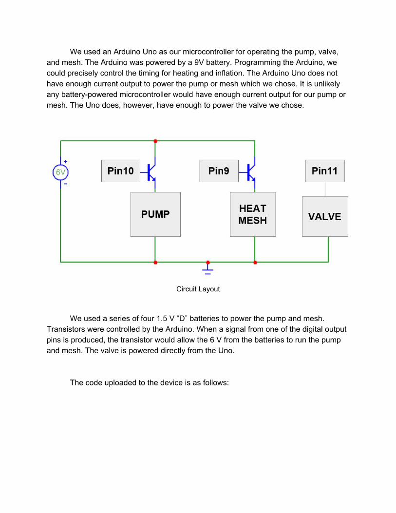
We used an Arduino Uno as our microcontroller for operating the pump, valve, and mesh. The Arduino was powered by a 9V battery. Programming the Arduino, we could precisely control the timing for heating and inflation. The Arduino Uno does not have enough current output to power the pump or mesh which we chose. It is unlikely any batterypowered microcontroller would have enough current output for our pump or mesh. The Uno does, however, have enough to power the valve we chose.
Circuit Layout
We used a series of four 1.5 V “D” batteries to power the pump and mesh. Transistors were controlled by the Arduino. When a signal from one of the digital output pins is produced, the transistor would allow the 6 V from the batteries to run the pump and mesh. The valve is powered directly from the Uno.
The code uploaded to the device is as follows:

int meshPin = 9; int pumpPin = 10; int valvePin = 11; void setup() pinMode(pumpPin, OUTPUT); pinMode(valvePin, OUTPUT); pinMode(meshPin, OUTPUT); digitalWrite(pumpPin, HIGH); digitalWrite(meshPin, HIGH); delay(4500); digitalWrite(pumpPin, LOW); delay(85500); digitalWrite(meshPin, LOW); delay(34500); digitalWrite(valvePin, HIGH); delay(60000); digitalWrite(valvePin, LOW); digitalWrite(pumpPin, HIGH); digitalWrite(meshPin, HIGH); delay(4500); digitalWrite(pumpPin, LOW); delay(85500); digitalWrite(meshPin, LOW); delay(34500); digitalWrite(valvePin, HIGH); delay(60000); digitalWrite(valvePin, LOW);
The code defines the pins as outputs and sets up the cycle. The pump runs for 4.5 seconds to inflate the bladder. The first 90 seconds of the cycle the mesh is powered. 30 seconds after the mesh is depowered, the valve is opened and the pressure is released. After 60 seconds of rest, the same procedure is repeated. The code spans 6 minutes and 9 seconds. The user should only experience 5 minutes and 9 seconds, after which only the valve is open to ensure that it is fully deflated before the next uses.
Results Frame: FEA Analysis
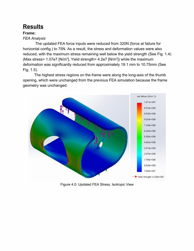
The updated FEA force inputs were reduced from 320N (force at failure for horizontal config.) to 75N. As a result, the stress and deformation values were also reduced, with the maximum stress remaining well below the yield strength (See Fig. 1.4) (Max stress= 1.07e7 [N/m2], Yield strength= 4.2e7 [N/m2]) while the maximum deformation was significantly reduced from approximately 19.1 mm to 10.75mm (See Fig. 1.5).
The highest stress regions on the frame were along the longaxis of the thumb opening, which were unchanged from the previous FEA simulation because the frame geometry was unchanged.
Figure 4.0: Updated FEA Stress, Isotropic View
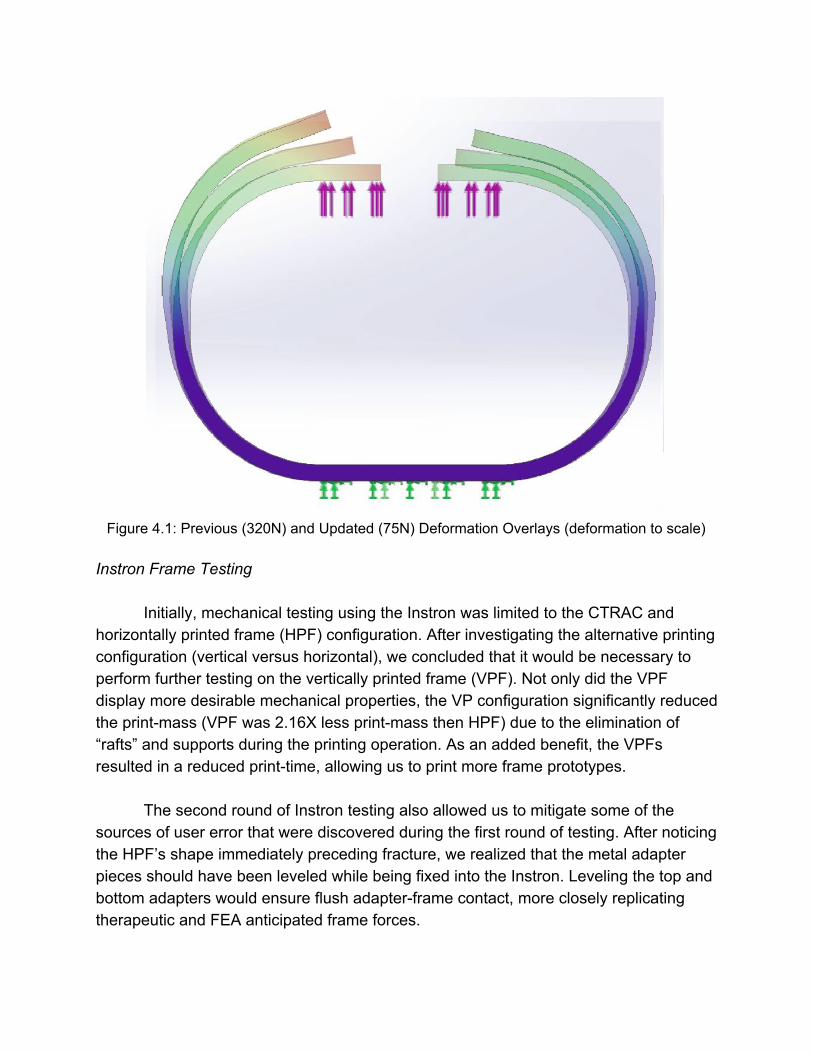
Figure 4.1: Previous (320N) and Updated (75N) Deformation Overlays (deformation to scale)
Instron Frame Testing
Initially, mechanical testing using the Instron was limited to the CTRAC and
horizontally printed frame (HPF) configuration. After investigating the alternative printing configuration (vertical versus horizontal), we concluded that it would be necessary to perform further testing on the vertically printed frame (VPF). Not only did the VPF display more desirable mechanical properties, the VP configuration significantly reduced the printmass (VPF was 2.16X less printmass then HPF) due to the elimination of “rafts” and supports during the printing operation. As an added benefit, the VPFs resulted in a reduced printtime, allowing us to print more frame prototypes. The second round of Instron testing also allowed us to mitigate some of the sources of user error that were discovered during the first round of testing. After noticing the HPF’s shape immediately preceding fracture, we realized that the metal adapter pieces should have been leveled while being fixed into the Instron. Leveling the top and bottom adapters would ensure flush adapterframe contact, more closely replicating therapeutic and FEA anticipated frame forces.
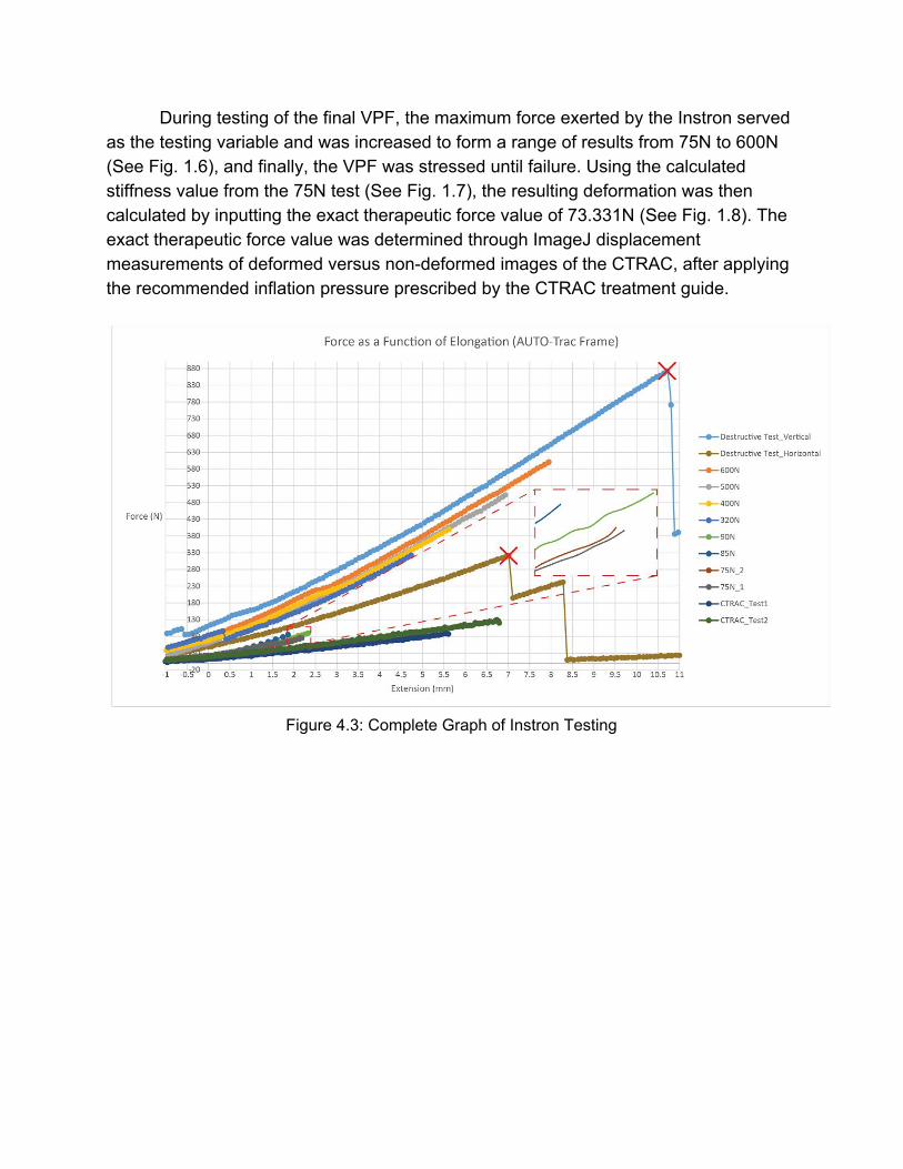
During testing of the final VPF, the maximum force exerted by the Instron served as the testing variable and was increased to form a range of results from 75N to 600N (See Fig. 1.6), and finally, the VPF was stressed until failure. Using the calculated stiffness value from the 75N test (See Fig. 1.7), the resulting deformation was then calculated by inputting the exact therapeutic force value of 73.331N (See Fig. 1.8). The exact therapeutic force value was determined through ImageJ displacement measurements of deformed versus nondeformed images of the CTRAC, after applying the recommended inflation pressure prescribed by the CTRAC treatment guide.
Figure 4.3: Complete Graph of Instron Testing
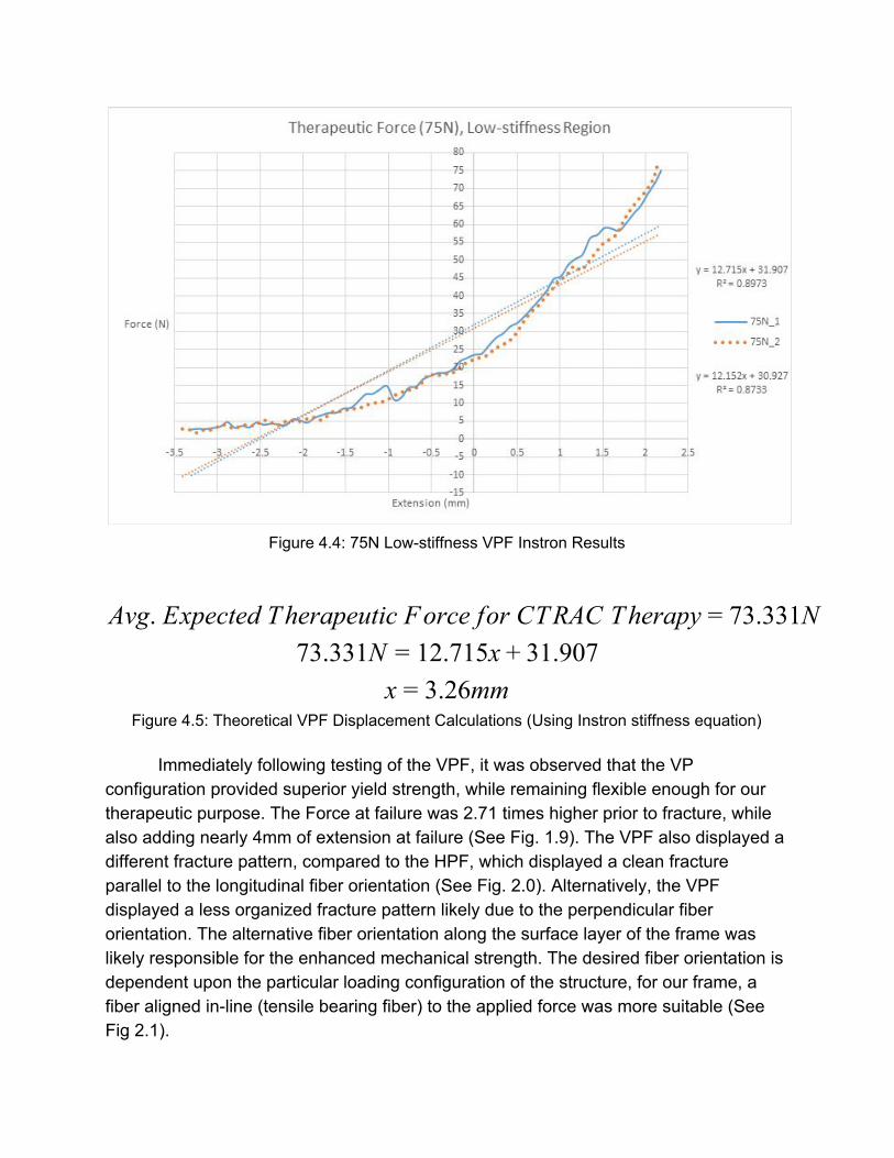
Figure 4.4: 75N Lowstiffness VPF Instron Results
vg. Expected Therapeutic Force for CTRAC Therapy 3.331NA = 7 3.331N 2.715x 1.9077 = 1 + 3
.26mmx = 3 Figure 4.5: Theoretical VPF Displacement Calculations (Using Instron stiffness equation)
Immediately following testing of the VPF, it was observed that the VP configuration provided superior yield strength, while remaining flexible enough for our therapeutic purpose. The Force at failure was 2.71 times higher prior to fracture, while also adding nearly 4mm of extension at failure (See Fig. 1.9). The VPF also displayed a different fracture pattern, compared to the HPF, which displayed a clean fracture parallel to the longitudinal fiber orientation (See Fig. 2.0). Alternatively, the VPF displayed a less organized fracture pattern likely due to the perpendicular fiber orientation. The alternative fiber orientation along the surface layer of the frame was likely responsible for the enhanced mechanical strength. The desired fiber orientation is dependent upon the particular loading configuration of the structure, for our frame, a fiber aligned inline (tensile bearing fiber) to the applied force was more suitable (See Fig 2.1).
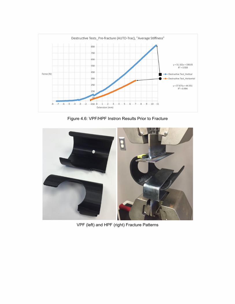
Figure 4.6: VPF/HPF Instron Results Prior to Fracture
VPF (left) and HPF (right) Fracture Patterns
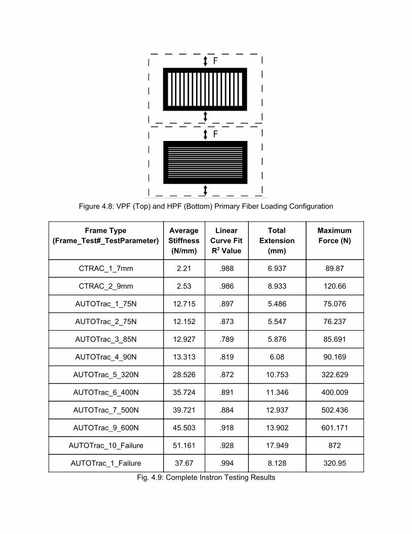
Figure 4.8: VPF (Top) and HPF (Bottom) Primary Fiber Loading Configuration
Frame Type (Frame_Test#_TestParameter)
Average Stiffness (N/mm)
Linear Curve Fit R2 Value
Total Extension (mm)
Maximum Force (N)
CTRAC_1_7mm 2.21 .988 6.937 89.87
CTRAC_2_9mm 2.53 .986 8.933 120.66
AUTOTrac_1_75N 12.715 .897 5.486 75.076
AUTOTrac_2_75N 12.152 .873 5.547 76.237
AUTOTrac_3_85N 12.927 .789 5.876 85.691
AUTOTrac_4_90N 13.313 .819 6.08 90.169
AUTOTrac_5_320N 28.526 .872 10.753 322.629
AUTOTrac_6_400N 35.724 .891 11.346 400.009
AUTOTrac_7_500N 39.721 .884 12.937 502.436
AUTOTrac_9_600N 45.503 .918 13.902 601.171
AUTOTrac_10_Failure 51.161 .928 17.949 872
AUTOTrac_1_Failure 37.67 .994 8.128 320.95
Fig. 4.9: Complete Instron Testing Results
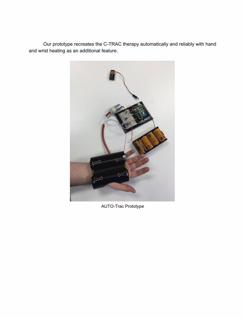
Our prototype recreates the CTRAC therapy automatically and reliably with hand and wrist heating as an additional feature.
AUTOTrac Prototype
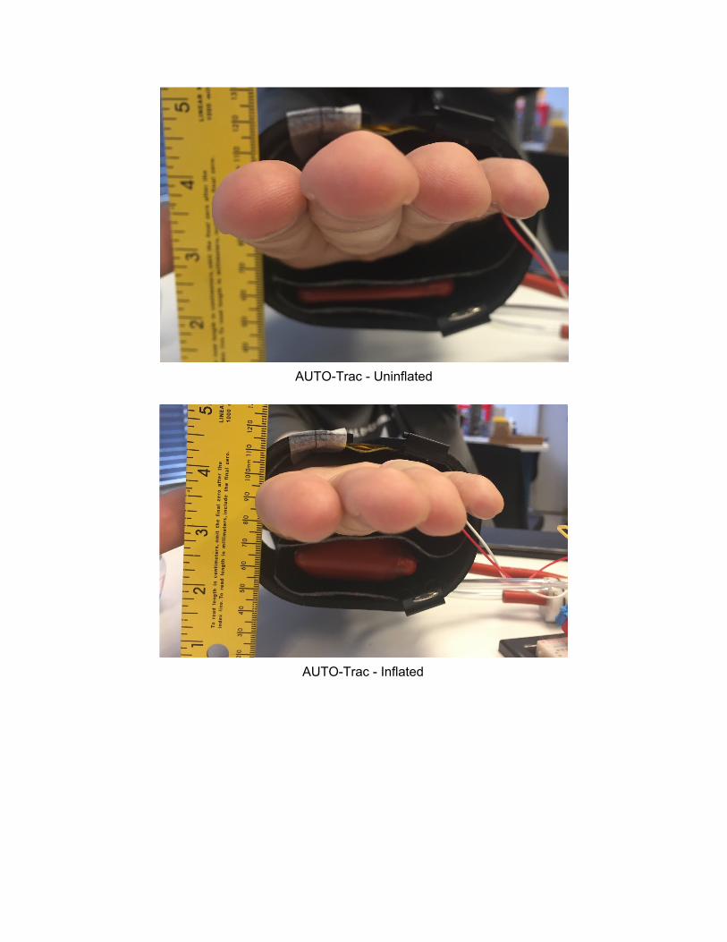
AUTOTrac Uninflated
AUTOTrac Inflated
Discussion and Future Work
The CTRAC is a Class I medical device as defined by the FDA. If marketed, the
AUTOTrac would be a Class II medical device, claiming substantial equivalence to other Class II medical devices such as automatic blood pressure monitors and heating blankets. The AUTOTrac would thus be subject to the same safety regulations. The current prototype does not incorporate any thermal or pressure sensors for feedback regulation of the heating and inflation. These would be needed to guard against overinflation and overheating and to meet FDA safety standards
A randomized controlled trial comparing the effectiveness of the AUTOTrac and CTRAC will be necessary to prove the superiority of our design for alleviation of CTS symptoms. Ideally, a sample of 150 CTS patients would be split into three groups of 50. One group would receive the AUTOTrac treatment. Another group would receive the CTRAC treatment. The last group would receive no treatment. The trial would track patients over six weeks and include a oneyear follow up.
The AUTOTrac can be developed further to be even more effective at combating CTS symptoms. The initial CTRAC regimen upon which the AUTOTrac was based (two minutes of pressure, a minute rest, and another two minutes of pressure) seems largely arbitrary with no physiological basis. With even the pressure with which the CTRAC is to be inflated (180200 mmHg) does not seem to have any firm footing in the physiology of the hand, wrist, or carpal tunnel. The automatic and programmable nature of the AUTOTrac allows for optimization studies wherein, if the current AUTOTrac treatment were shown to be effective, one could determine the most effective treatment. Heating duration, heating intensity, maximum pressure, pressure duration, and cycle time are all variables which could be easily manipulated and examined. It may be the case that there is no general, most effective treatment, but there may be a most effective treatment specific to any individual user with CTS.

Acknowledgments:
We thank LEGENDS Entrepreneurial Student Awards for generously funding our project, Mary Barber, OT for information about current CTS therapy and heating during stretching, Professor Ken Cook for last minute circuit design help, and the Biomedical Engineering Department for facilities, materials, and support.