Embed Size (px)
Citation preview
1
ERTMS/ETCS Level 2 high speed / high capacity lines feedback on RAMS and performance parameters: experience after two years of commercial service in Italy and features of the new
HS/HC Italian lines.
Enzo Marzilli, F.Senesi, D.Caronti, N.Filippini, R.Malangone, U.Foschi, M.Ciaffi, M.Frandi Rete Ferroviaria Italiana,, Rome, Italy
Abstract
The article has been developed on the base of some lessons-learned by RFI, after two years from the implementation of ERTMS/ETCS Level 2 on the Rome-Naples and Turin-Novara high speed/high capacity lines. The implementation of ERTMS/ETCS Level 2 allowed getting interesting performances of ERTMS on a commercial point of view. In particular the structuring of the architecture of the ERTMS/ETCS Level 2 with suitable interfaces has concurred to gain RAMS performances that allowed meaningful income and trends in returns on investment for RFI within this period. Most detailed technical information concerning this successful structure of ERTMS/ETCS Level 2 system and interfaces is provided herein, by including related performances, RAMS, and those faults and degradations affecting the ERTMS in this period as well. This comprehensive information would be helpful in the estimation of the returns on investments for each time-slot, by putting a breakthrough in the evaluation of the economic trend of convenience in implementing the ERTMS, after just two years of commercial operation. Moreover, information upon the development of ERTMS network is extended to related interoperable corridors up to the next 5 years, for a comprehensive evaluation of the economical fallouts upon the ERTMS migration strategy of RFI. In the conclusions it is evidenced as the implementation of the ERTMS with a suitable architecture of its interfaces has turns out to provide profitable returns in the medium-long terms of system operation.
1-Introduction
The Infrastructure Managers and the Undertaking Companies in Europe have gradually started a process of introduction of innovative technologies (GSM-R, GPS, ERTMS, Computer Based Interlocking, and Command and Control Systems) in order to answer to the requirements of the market (passenger and freight traffic) with criteria of optimization of the resources, improving of safety standards, promotion of railway interoperability and standardization of the products.
2-Architecture and operation of High Speed Signalling Sub-System
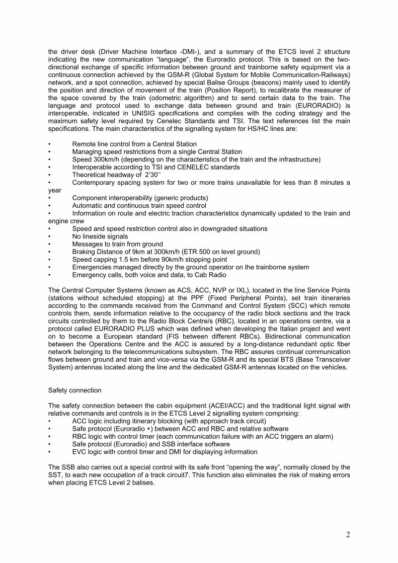
The signalling system for HS/HC lines comprises a line management subsystem used to control and command yard objects and train routes or itineraries and a train spacing subsystem. The two subsystems use a telecommunications subsystem to interface and dialogue with the trains. As previously mentioned, the signalling system for the Italian HS/HC lines comprises the ERTMS/ETCS Level 2 train spacing system with automatic train travel control and command. The above system achieves the ultimate aim of controlling train travel. Though it is naturally divided by the equipment fitted on the trains and moves with them (ETCS on-board subsystem) and the equipment that remains motionless on the ground (ETCS ground subsystem), it is extremely integrated at functional level. As regards signalling logic, each ETCS train spacing subsystem is complementary to the next. The two-directional flow of information achieved through the widespread use of telecommunication systems, GSM-R radio in particular, is absolutely innovative for the world of signalling. ERTMS/ETCS Level 2 generates integrated signalling functions directly in the driver's cab, train separation and travel control, and transfers a significant amount of signalling equipment from ground to train (the traditional fixed light signal is now on the driver's desk). Figure 4.1 illustrates the operating principle of ERTMS/ETCS Level 2. It shows the Air Gap interface between the ground subsystem (SST) and the on-board subsystem (SSB), the interface between the ground subsystem components, a diagram of the main steps for calculating an emergency braking curve and the relative display on
2
the driver desk (Driver Machine Interface -DMI-), and a summary of the ETCS level 2 structure indicating the new communication “language”, the Euroradio protocol. This is based on the two-directional exchange of specific information between ground and trainborne safety equipment via a continuous connection achieved by the GSM-R (Global System for Mobile Communication-Railways) network, and a spot connection, achieved by special Balise Groups (beacons) mainly used to identify the position and direction of movement of the train (Position Report), to recalibrate the measurer of the space covered by the train (odometric algorithm) and to send certain data to the train. The language and protocol used to exchange data between ground and train (EURORADIO) is interoperable, indicated in UNISIG specifications and complies with the coding strategy and the maximum safety level required by Cenelec Standards and TSI. The text references list the main specifications. The main characteristics of the signalling system for HS/HC lines are: • Remote line control from a Central Station • Managing speed restrictions from a single Central Station • Speed 300km/h (depending on the characteristics of the train and the infrastructure) • Interoperable according to TSI and CENELEC standards • Theoretical headway of 2’30’’ • Contemporary spacing system for two or more trains unavailable for less than 8 minutes a year • Component interoperability (generic products) • Automatic and continuous train speed control • Information on route and electric traction characteristics dynamically updated to the train and engine crew • Speed and speed restriction control also in downgraded situations • No lineside signals • Messages to train from ground • Braking Distance of 9km at 300km/h (ETR 500 on level ground) • Speed capping 1.5 km before 90km/h stopping point • Emergencies managed directly by the ground operator on the trainborne system • Emergency calls, both voice and data, to Cab Radio The Central Computer Systems (known as ACS, ACC, NVP or IXL), located in the line Service Points (stations without scheduled stopping) at the PPF (Fixed Peripheral Points), set train itineraries according to the commands received from the Command and Control System (SCC) which remote controls them, sends information relative to the occupancy of the radio block sections and the track circuits controlled by them to the Radio Block Centre/s (RBC), located in an operations centre, via a protocol called EURORADIO PLUS which was defined when developing the Italian project and went on to become a European standard (FIS between different RBCs). Bidirectional communication between the Operations Centre and the ACC is assured by a long-distance redundant optic fiber network belonging to the telecommunications subsystem. The RBC assures continual communication flows between ground and train and vice-versa via the GSM-R and its special BTS (Base Transceiver System) antennas located along the line and the dedicated GSM-R antennas located on the vehicles. Safety connection The safety connection between the cabin equipment (ACEI/ACC) and the traditional light signal with relative commands and controls is in the ETCS Level 2 signalling system comprising: • ACC logic including itinerary blocking (with approach track circuit) • Safe protocol (Euroradio +) between ACC and RBC and relative software • RBC logic with control timer (each communication failure with an ACC triggers an alarm) • Safe protocol (Euroradio) and SSB interface software • EVC logic with control timer and DMI for displaying information The SSB also carries out a special control with its safe front “opening the way”, normally closed by the SST, to each new occupation of a track circuit7. This function also eliminates the risk of making errors when placing ETCS Level 2 balises.
3
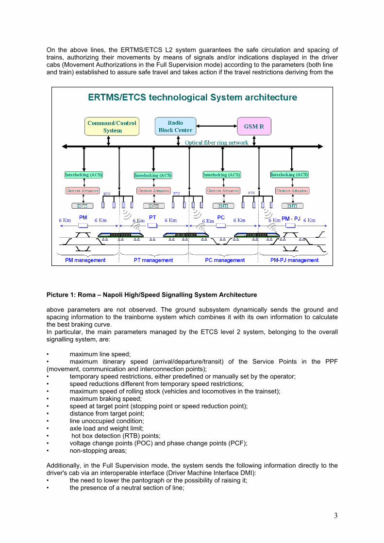
On the above lines, the ERTMS/ETCS L2 system guarantees the safe circulation and spacing of trains, authorizing their movements by means of signals and/or indications displayed in the driver cabs (Movement Authorizations in the Full Supervision mode) according to the parameters (both line and train) established to assure safe travel and takes action if the travel restrictions deriving from the
Picture 1: Roma – Napoli High/Speed Signalling System Architecture above parameters are not observed. The ground subsystem dynamically sends the ground and spacing information to the trainborne system which combines it with its own information to calculate the best braking curve. In particular, the main parameters managed by the ETCS level 2 system, belonging to the overall signalling system, are: • maximum line speed; • maximum itinerary speed (arrival/departure/transit) of the Service Points in the PPF (movement, communication and interconnection points); • temporary speed restrictions, either predefined or manually set by the operator; • speed reductions different from temporary speed restrictions; • maximum speed of rolling stock (vehicles and locomotives in the trainset); • maximum braking speed; • speed at target point (stopping point or speed reduction point); • distance from target point; • line unoccupied condition; • axle load and weight limit; • hot box detection (RTB) points; • voltage change points (POC) and phase change points (PCF); • non-stopping areas; Additionally, in the Full Supervision mode, the system sends the following information directly to the driver's cab via an interoperable interface (Driver Machine Interface DMI): • the need to lower the pantograph or the possibility of raising it; • the presence of a neutral section of line;
4
• specific areas where shunting and reversing maneuvers are allowed by the system. The ETCS system features different operating modes and, depending on the existence or not of degraded situations, allows full or partial supervision of train travel. The Full Supervision train travel operating mode assumes the entire ERTMS/ETCS L2 system is working correctly. In the event of special line degrading situations (e.g.: irregularities in a track circuit or point) the system can provide Partial Supervision by: • granting train movement authorizations with control by the system and travel on sight, never exceeding 30 km/h (Movement Authorizations with Travel on Sight - On Sight Mode). In this operating mode, the system sets maximum speed to 30 km/h or even less; • authorizing train movement in respect of the 30 km/h (default value) or 60 km/h speed limit entered by the engine crew following receipt of a special movement prescription (Movement Authorizations with Special Prescriptions - STAFF Responsible Mode). In the above modes, the system directly communicates the relative mode and the instantaneous speed of the train to the driver's cab. The main information exchanged between the on-board and the trackside systems to ensure the system works properly is: Train-to-Track: Position Report (PR) This is a radio message containing, among other things, the position, operating mode, speed and direction of the train, MA request. Track-to-Train: Movement Authority (MA) Depending on the Interlocking status (ACC/IXL), the state of the track circuits, itineraries, etc., the preconfigured line data (maximum speeds, gradients, etc.) and the information received from the train via PR, RBC generates the MA (periodically and/or on request) and sends it to the train together with the Static Speed Profiles (SSP) of the line from which the on-board system will calculate the Most Restrictive Speed Profile and then, depending on the Movement Authority, the braking curve of the Dynamic Speed Profile. Track-to-Train and Train-to-Track information acquisition acknowledgements. The system is based on fixed position markers comprising balises (transponders) located on the railway sleepers 200 meters before each electric end-of-track circuit joint in both directions of travel and known to the RBC, and on the calculation of the space covered by the trains starting from these points (also used to correct any position errors calculated by the SSB odometric devices). Information is continuously exchanged between SST and SSB via the GSM-R radio telecommunication network. Each train allots at least one communication channel to the latter. On ERTMS/ETCS Level 2 lines there are neither trackside light signals nor fixed shunting signals as the signals received in the cab are normally sufficient to drive the trains. External non-luminous signalling has been installed in order to handle downgrade situations. This, analysed at a later stage, identifies the division of the railway infrastructure required by the signalling system and ETCS Level 2 and achieves train spacing in the Radio Block Sections. In normal conditions (Full Supervision - FS), Operations Centre of the system authorises trains to enter a section of line (Movement Authority - MA) only after checking: • the position of the train; • that the characteristics of the train are compatible with those of the section; • that all MA previously granted to other trains for that section are no longer valid; • there are no active system alarms (e.g.: Emergency); Additionally, the system must have received confirmation from suitable systems and devices that the section is unoccupied and available (correct direction of circulation or any blocked itineraries). If the section is occupied, but no MA previously sent to other trains for it are valid, the system may send the train authorisation to enter the section in the On Sight (OS) partial supervision mode which comes into effect after driver acknowledgement is performed. If one of the conditions required for sending an FS or OS MA is not met, the train may enter the section in the STAFF Responsible (SR) mode after the engine crew sends a specific request to DCO with node acknowledgement.
5
3-New features
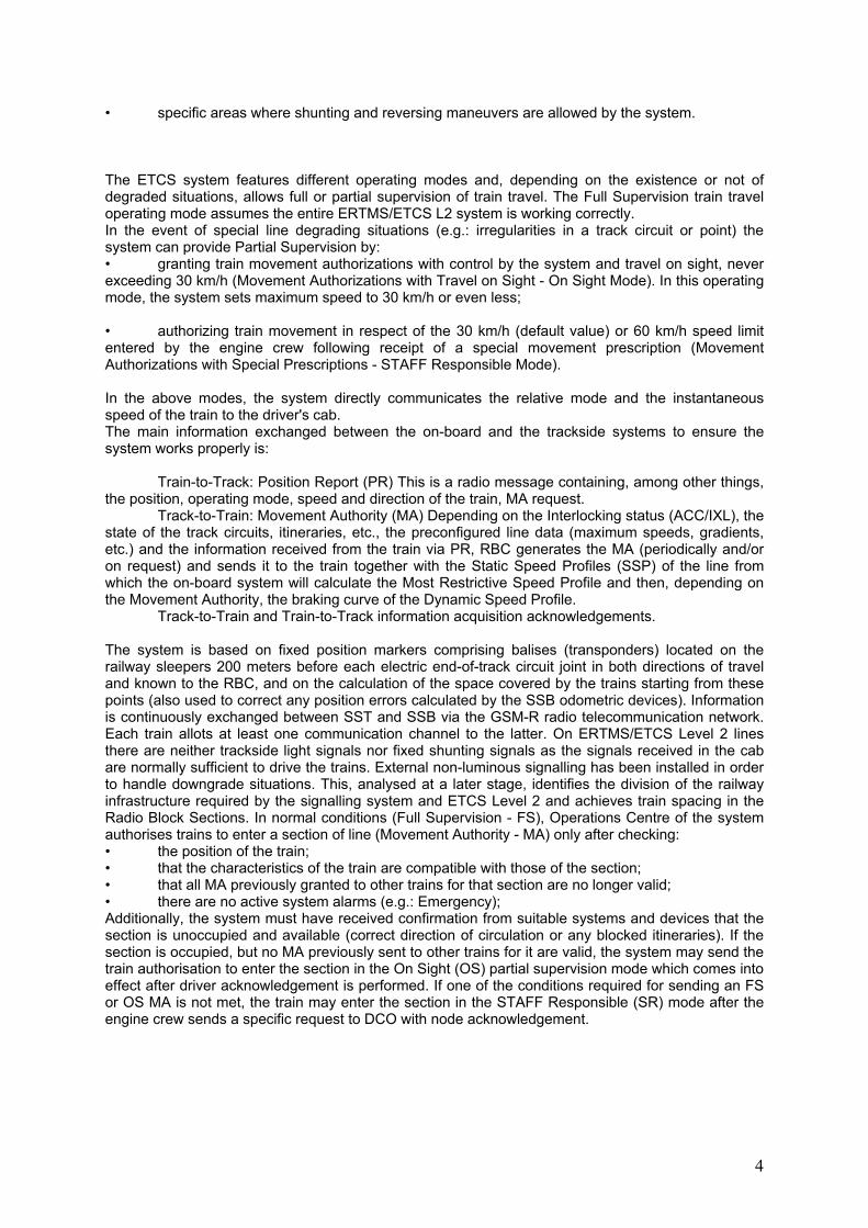
DISTRIBUTED (MULTISTATION) INTERLOCKING The Italian next-to-be-opened High Speed/High Capacity ERTMS lines (Milano-Bologna and Bologna-Firenze) will be provided by new features concerning the interlockings: the Distributed or Multi-station Computer Based Interlocking. This new technology enables the extension of vital controls from a single control centre over a whole railway line with several stations.The core of the system: concentrated logic for a distributed service is a technologically integrated system able to manage, from a single main station, the signalling systems of several stations on a line, with the same reliability of a classic computer based interlocking, but also implementing supervision facilities
Picture 2: Distributed (“Multi-Station”) Interlocking
4- Availability and Reliability Requirements
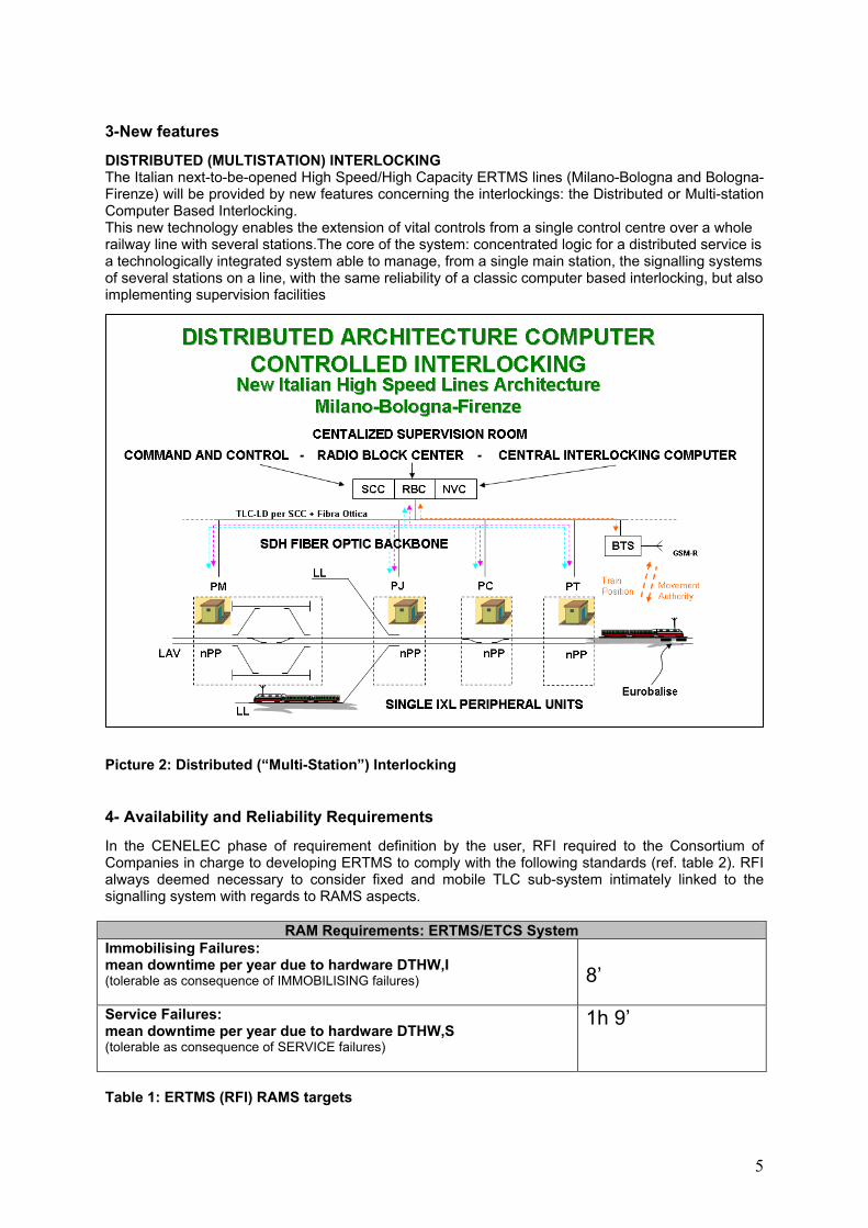
In the CENELEC phase of requirement definition by the user, RFI required to the Consortium of Companies in charge to developing ERTMS to comply with the following standards (ref. table 2). RFI always deemed necessary to consider fixed and mobile TLC sub-system intimately linked to the signalling system with regards to RAMS aspects.
RAM Requirements: ERTMS/ETCS System Immobilising Failures: mean downtime per year due to hardware DTHW,I (tolerable as consequence of IMMOBILISING failures)
8’
Service Failures: mean downtime per year due to hardware DTHW,S (tolerable as consequence of SERVICE failures)
1h 9’
Table 1: ERTMS (RFI) RAMS targets
6
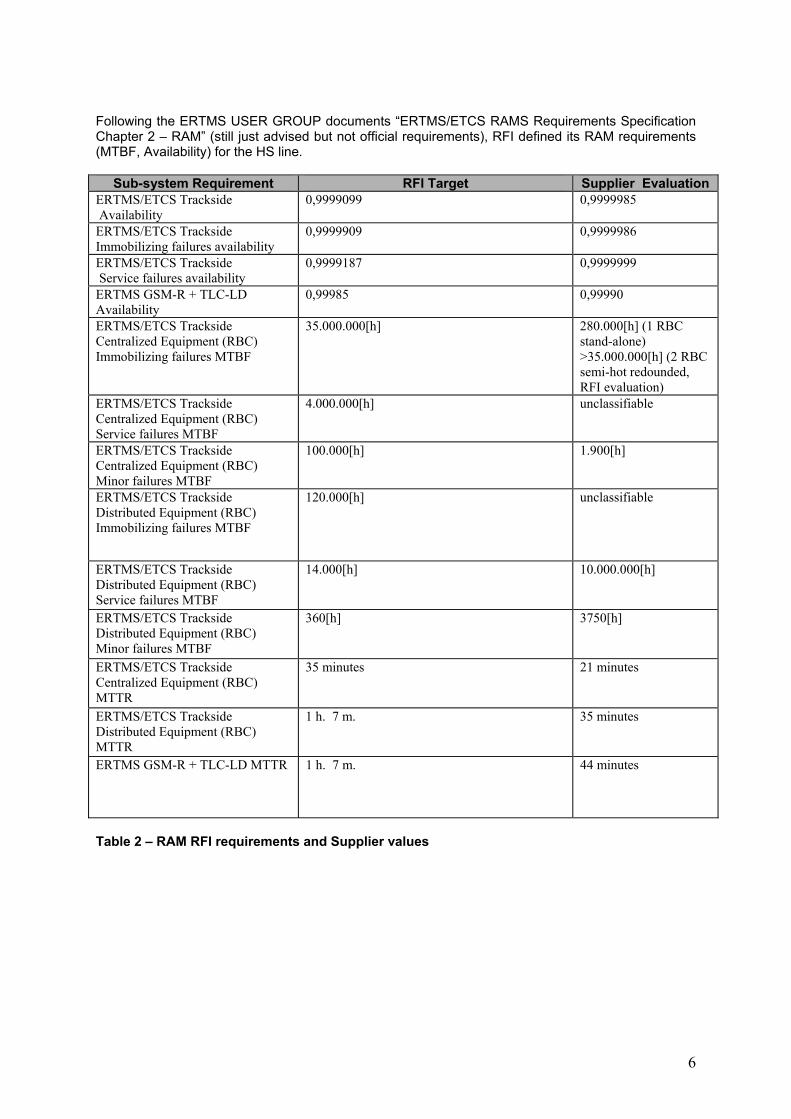
Following the ERTMS USER GROUP documents “ERTMS/ETCS RAMS Requirements Specification Chapter 2 – RAM” (still just advised but not official requirements), RFI defined its RAM requirements (MTBF, Availability) for the HS line.
Sub-system Requirement RFI Target Supplier EvaluationERTMS/ETCS Trackside Availability
0,9999099 0,9999985
ERTMS/ETCS Trackside Immobilizing failures availability
0,9999909 0,9999986
ERTMS/ETCS Trackside Service failures availability
0,9999187 0,9999999
ERTMS GSM-R + TLC-LD Availability
0,99985
0,99990
ERTMS/ETCS Trackside Centralized Equipment (RBC) Immobilizing failures MTBF
35.000.000[h] 280.000[h] (1 RBC stand-alone) >35.000.000[h] (2 RBC semi-hot redounded, RFI evaluation)
ERTMS/ETCS Trackside Centralized Equipment (RBC) Service failures MTBF
4.000.000[h] unclassifiable
ERTMS/ETCS Trackside Centralized Equipment (RBC) Minor failures MTBF
100.000[h] 1.900[h]
ERTMS/ETCS Trackside Distributed Equipment (RBC) Immobilizing failures MTBF
120.000[h] unclassifiable
ERTMS/ETCS Trackside Distributed Equipment (RBC) Service failures MTBF
14.000[h] 10.000.000[h]
ERTMS/ETCS Trackside Distributed Equipment (RBC) Minor failures MTBF
360[h] 3750[h]
ERTMS/ETCS Trackside Centralized Equipment (RBC) MTTR
35 minutes 21 minutes
ERTMS/ETCS Trackside Distributed Equipment (RBC) MTTR
1 h. 7 m. 35 minutes
ERTMS GSM-R + TLC-LD MTTR 1 h. 7 m. 44 minutes
Table 2 – RAM RFI requirements and Supplier values
7
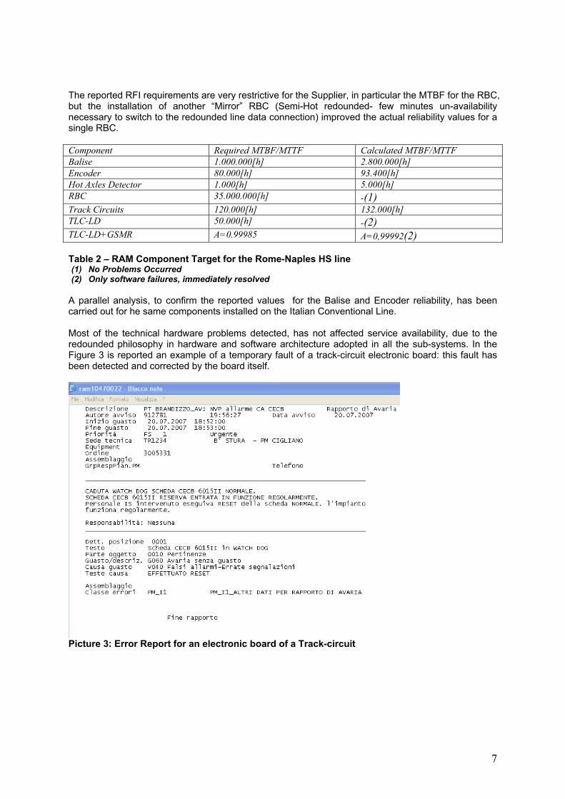
The reported RFI requirements are very restrictive for the Supplier, in particular the MTBF for the RBC, but the installation of another “Mirror” RBC (Semi-Hot redounded- few minutes un-availability necessary to switch to the redounded line data connection) improved the actual reliability values for a single RBC. Component Required MTBF/MTTF Calculated MTBF/MTTF Balise 1.000.000[h] 2.800.000[h] Encoder 80.000[h] 93.400[h] Hot Axles Detector 1.000[h] 5.000[h] RBC 35.000.000[h] -(1) Track Circuits 120.000[h] 132.000[h] TLC-LD 50.000[h] -(2) TLC-LD+GSMR A=0.99985 A=0,99992(2) Table 2 – RAM Component Target for the Rome-Naples HS line (1) No Problems Occurred (2) Only software failures, immediately resolved
A parallel analysis, to confirm the reported values for the Balise and Encoder reliability, has been carried out for he same components installed on the Italian Conventional Line. Most of the technical hardware problems detected, has not affected service availability, due to the redounded philosophy in hardware and software architecture adopted in all the sub-systems. In the Figure 3 is reported an example of a temporary fault of a track-circuit electronic board: this fault has been detected and corrected by the board itself.
Picture 3: Error Report for an electronic board of a Track-circuit
8
5- Time related performances
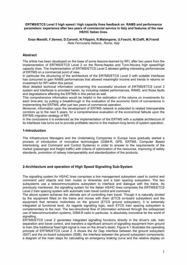
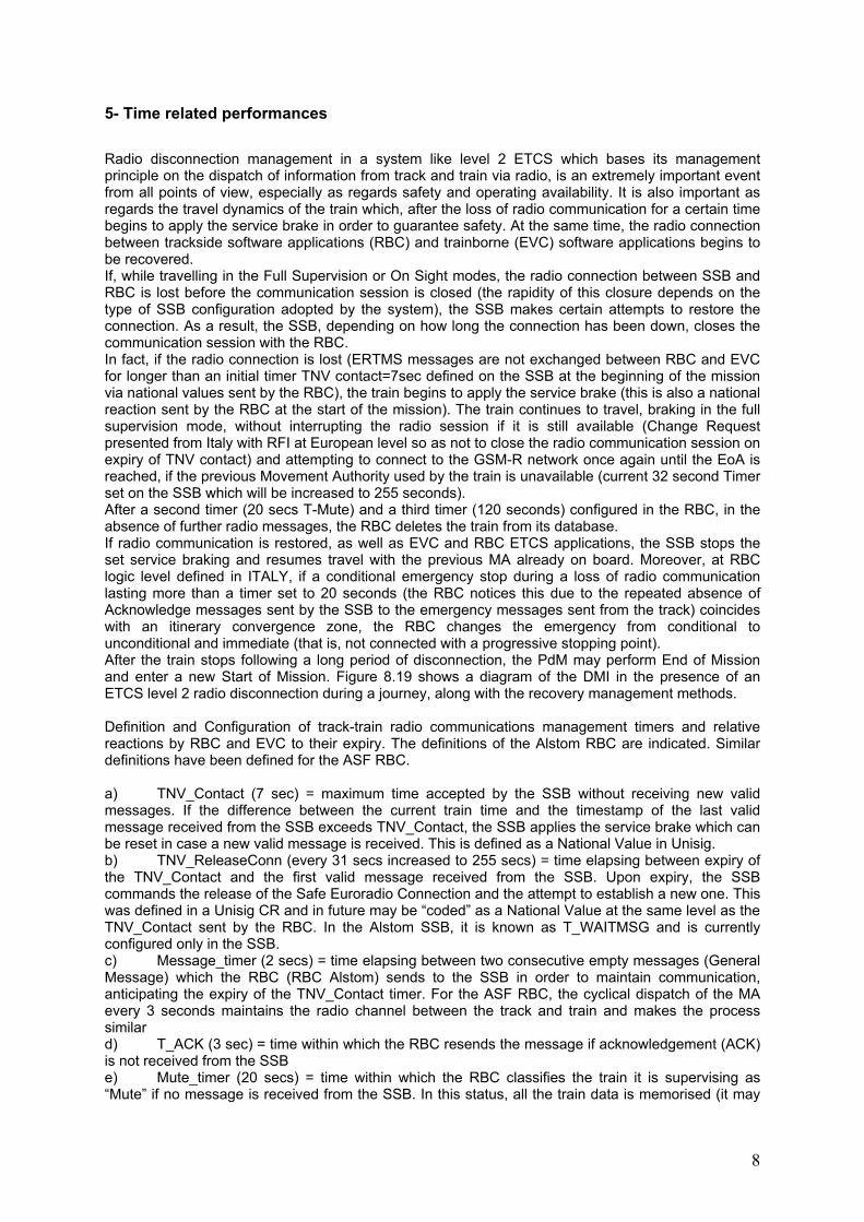
Radio disconnection management in a system like level 2 ETCS which bases its management principle on the dispatch of information from track and train via radio, is an extremely important event from all points of view, especially as regards safety and operating availability. It is also important as regards the travel dynamics of the train which, after the loss of radio communication for a certain time begins to apply the service brake in order to guarantee safety. At the same time, the radio connection between trackside software applications (RBC) and trainborne (EVC) software applications begins to be recovered. If, while travelling in the Full Supervision or On Sight modes, the radio connection between SSB and RBC is lost before the communication session is closed (the rapidity of this closure depends on the type of SSB configuration adopted by the system), the SSB makes certain attempts to restore the connection. As a result, the SSB, depending on how long the connection has been down, closes the communication session with the RBC. In fact, if the radio connection is lost (ERTMS messages are not exchanged between RBC and EVC for longer than an initial timer TNV contact=7sec defined on the SSB at the beginning of the mission via national values sent by the RBC), the train begins to apply the service brake (this is also a national reaction sent by the RBC at the start of the mission). The train continues to travel, braking in the full supervision mode, without interrupting the radio session if it is still available (Change Request presented from Italy with RFI at European level so as not to close the radio communication session on expiry of TNV contact) and attempting to connect to the GSM-R network once again until the EoA is reached, if the previous Movement Authority used by the train is unavailable (current 32 second Timer set on the SSB which will be increased to 255 seconds). After a second timer (20 secs T-Mute) and a third timer (120 seconds) configured in the RBC, in the absence of further radio messages, the RBC deletes the train from its database. If radio communication is restored, as well as EVC and RBC ETCS applications, the SSB stops the set service braking and resumes travel with the previous MA already on board. Moreover, at RBC logic level defined in ITALY, if a conditional emergency stop during a loss of radio communication lasting more than a timer set to 20 seconds (the RBC notices this due to the repeated absence of Acknowledge messages sent by the SSB to the emergency messages sent from the track) coincides with an itinerary convergence zone, the RBC changes the emergency from conditional to unconditional and immediate (that is, not connected with a progressive stopping point). After the train stops following a long period of disconnection, the PdM may perform End of Mission and enter a new Start of Mission. Figure 8.19 shows a diagram of the DMI in the presence of an ETCS level 2 radio disconnection during a journey, along with the recovery management methods. Definition and Configuration of track-train radio communications management timers and relative reactions by RBC and EVC to their expiry. The definitions of the Alstom RBC are indicated. Similar definitions have been defined for the ASF RBC. a) TNV_Contact (7 sec) = maximum time accepted by the SSB without receiving new valid messages. If the difference between the current train time and the timestamp of the last valid message received from the SSB exceeds TNV_Contact, the SSB applies the service brake which can be reset in case a new valid message is received. This is defined as a National Value in Unisig. b) TNV_ReleaseConn (every 31 secs increased to 255 secs) = time elapsing between expiry of the TNV_Contact and the first valid message received from the SSB. Upon expiry, the SSB commands the release of the Safe Euroradio Connection and the attempt to establish a new one. This was defined in a Unisig CR and in future may be “coded” as a National Value at the same level as the TNV_Contact sent by the RBC. In the Alstom SSB, it is known as T_WAITMSG and is currently configured only in the SSB. c) Message_timer (2 secs) = time elapsing between two consecutive empty messages (General Message) which the RBC (RBC Alstom) sends to the SSB in order to maintain communication, anticipating the expiry of the TNV_Contact timer. For the ASF RBC, the cyclical dispatch of the MA every 3 seconds maintains the radio channel between the track and train and makes the process similar d) T_ACK (3 sec) = time within which the RBC resends the message if acknowledgement (ACK) is not received from the SSB e) Mute_timer (20 secs) = time within which the RBC classifies the train it is supervising as “Mute” if no message is received from the SSB. In this status, all the train data is memorised (it may
9
be used upon reception of a subsequent valid message received from the SSB) but no Movement Authority is generated for this train. f) Reception_timer (120 sec) = time within which RBC deletes the train from its database if no message is received from the SSB.
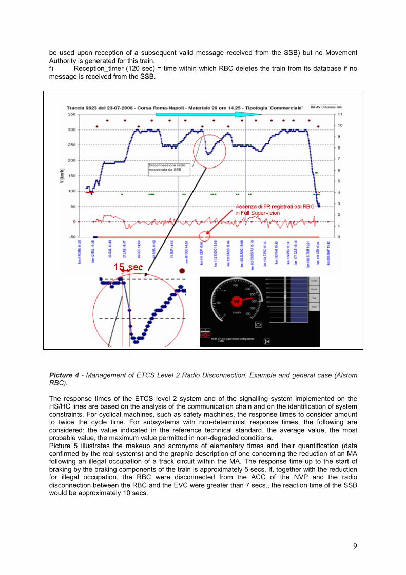
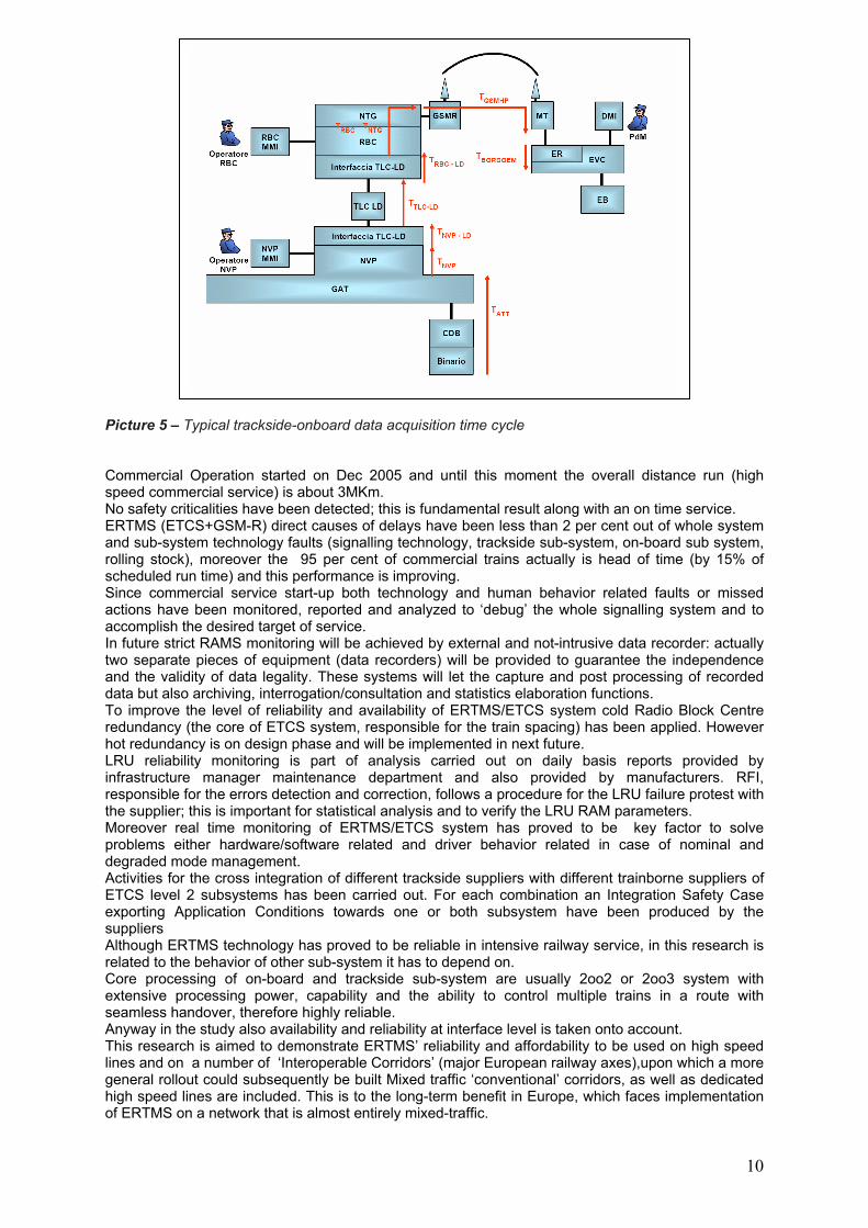
Picture 4 - Management of ETCS Level 2 Radio Disconnection. Example and general case (Alstom RBC). The response times of the ETCS level 2 system and of the signalling system implemented on the HS/HC lines are based on the analysis of the communication chain and on the identification of system constraints. For cyclical machines, such as safety machines, the response times to consider amount to twice the cycle time. For subsystems with non-determinist response times, the following are considered: the value indicated in the reference technical standard, the average value, the most probable value, the maximum value permitted in non-degraded conditions. Picture 5 illustrates the makeup and acronyms of elementary times and their quantification (data confirmed by the real systems) and the graphic description of one concerning the reduction of an MA following an illegal occupation of a track circuit within the MA. The response time up to the start of braking by the braking components of the train is approximately 5 secs. If, together with the reduction for illegal occupation, the RBC were disconnected from the ACC of the NVP and the radio disconnection between the RBC and the EVC were greater than 7 secs., the reaction time of the SSB would be approximately 10 secs.
10
Picture 5 – Typical trackside-onboard data acquisition time cycle Commercial Operation started on Dec 2005 and until this moment the overall distance run (high speed commercial service) is about 3MKm. No safety criticalities have been detected; this is fundamental result along with an on time service. ERTMS (ETCS+GSM-R) direct causes of delays have been less than 2 per cent out of whole system and sub-system technology faults (signalling technology, trackside sub-system, on-board sub system, rolling stock), moreover the 95 per cent of commercial trains actually is head of time (by 15% of scheduled run time) and this performance is improving. Since commercial service start-up both technology and human behavior related faults or missed actions have been monitored, reported and analyzed to ‘debug’ the whole signalling system and to accomplish the desired target of service. In future strict RAMS monitoring will be achieved by external and not-intrusive data recorder: actually two separate pieces of equipment (data recorders) will be provided to guarantee the independence and the validity of data legality. These systems will let the capture and post processing of recorded data but also archiving, interrogation/consultation and statistics elaboration functions. To improve the level of reliability and availability of ERTMS/ETCS system cold Radio Block Centre redundancy (the core of ETCS system, responsible for the train spacing) has been applied. However hot redundancy is on design phase and will be implemented in next future. LRU reliability monitoring is part of analysis carried out on daily basis reports provided by infrastructure manager maintenance department and also provided by manufacturers. RFI, responsible for the errors detection and correction, follows a procedure for the LRU failure protest with the supplier; this is important for statistical analysis and to verify the LRU RAM parameters. Moreover real time monitoring of ERTMS/ETCS system has proved to be key factor to solve problems either hardware/software related and driver behavior related in case of nominal and degraded mode management. Activities for the cross integration of different trackside suppliers with different trainborne suppliers of ETCS level 2 subsystems has been carried out. For each combination an Integration Safety Case exporting Application Conditions towards one or both subsystem have been produced by the suppliers Although ERTMS technology has proved to be reliable in intensive railway service, in this research is related to the behavior of other sub-system it has to depend on. Core processing of on-board and trackside sub-system are usually 2oo2 or 2oo3 system with extensive processing power, capability and the ability to control multiple trains in a route with seamless handover, therefore highly reliable. Anyway in the study also availability and reliability at interface level is taken onto account. This research is aimed to demonstrate ERTMS’ reliability and affordability to be used on high speed lines and on a number of ‘Interoperable Corridors’ (major European railway axes),upon which a more general rollout could subsequently be built Mixed traffic ‘conventional’ corridors, as well as dedicated high speed lines are included. This is to the long-term benefit in Europe, which faces implementation of ERTMS on a network that is almost entirely mixed-traffic.
11
Non intrusive sniffing of RBC-MSC connections with decoding of Euroradio and V110 protocols
MSC
MSMS MSMS MSMS
Handover diBTS e RBC
Handover diBTS e RBC
Non intrusive sniffing of RBC-IXL connections with decoding of Euroradio++ protocol
3+1 PRI2Mbit/s
LDR Station
LDI / LMS
NTG
Access Server
MXP
TB RBC2
ChA
ChB
ChC
I/OA
I/OB
TB RBC1
ChA
ChB
ChC
I/OA
I/OB
RouterRouter
TLC-LDInterface
Hub switchRBC
VMMI
Sonda Sonda SMAVSMAV
Sonda Sonda SMAVSMAV
RouterRouter
TB RBC3
ChA
ChB
ChC
I/OA
I/OB
SERVER
Non intrusive sniffing of RBC-MSC connections with decoding of Euroradio and V110 protocols
MSC
MSMS MSMS MSMSMSMSMSMS MSMSMSMS MSMSMSMS
Handover diBTS e RBC
Handover diBTS e RBC
Non intrusive sniffing of RBC-IXL connections with decoding of Euroradio++ protocol
3+1 PRI2Mbit/s
LDR Station
LDI / LMS
NTG
Access Server
MXP
NTG
Access Server
MXP
TB RBC2
ChA
ChB
ChC
I/OA
I/OB
TB RBC2
ChA
ChB
ChC
I/OA
I/OB
TB RBC1
ChA
ChB
ChC
I/OA
I/OB
TB RBC1
ChA
ChB
ChC
I/OA
I/OB
RouterRouter
TLC-LDInterface
Hub switchRBC
VMMI
Sonda Sonda SMAVSMAV
Sonda Sonda SMAVSMAV
RouterRouter
TB RBC3
ChA
ChB
ChC
I/OA
I/OB
TB RBC3
ChA
ChB
ChC
I/OA
I/OB
SERVER
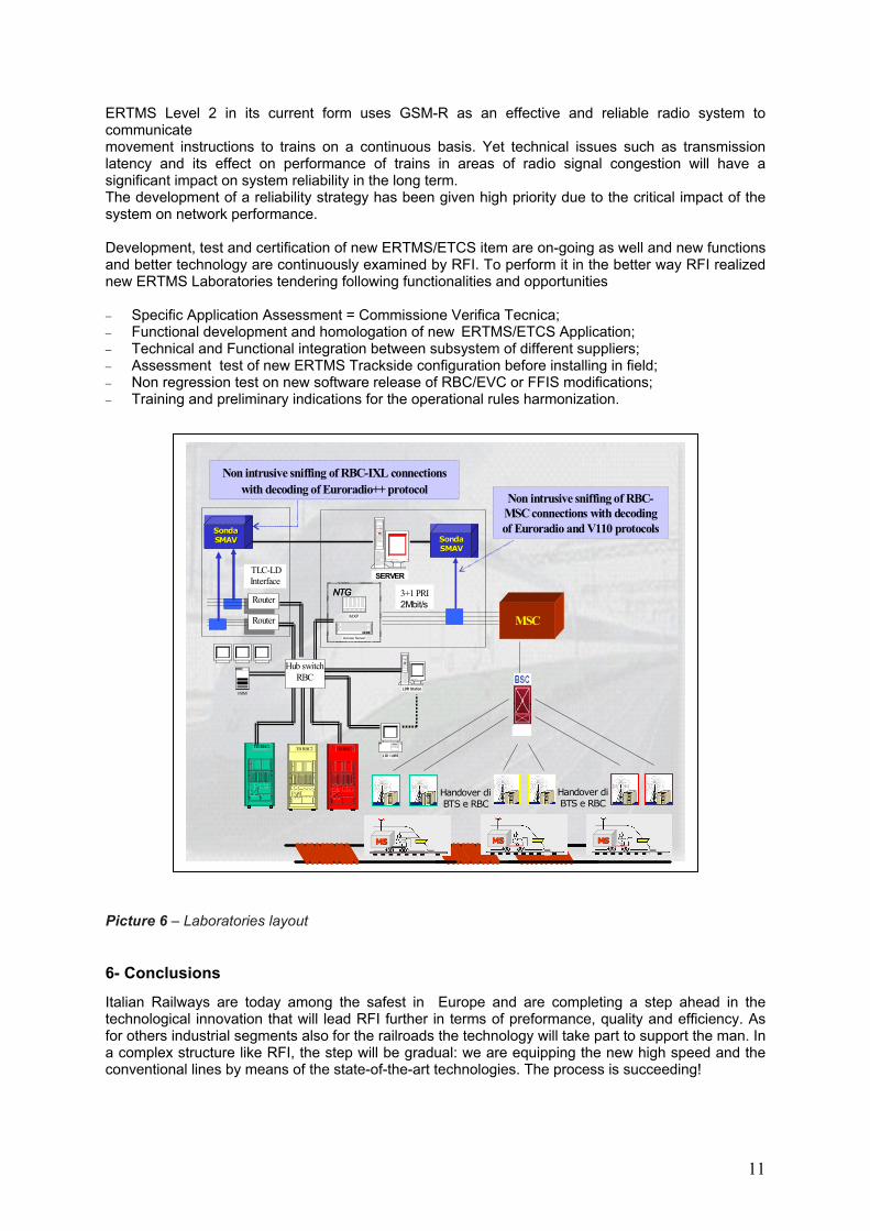
ERTMS Level 2 in its current form uses GSM-R as an effective and reliable radio system to communicate movement instructions to trains on a continuous basis. Yet technical issues such as transmission latency and its effect on performance of trains in areas of radio signal congestion will have a significant impact on system reliability in the long term. The development of a reliability strategy has been given high priority due to the critical impact of the system on network performance. Development, test and certification of new ERTMS/ETCS item are on-going as well and new functions and better technology are continuously examined by RFI. To perform it in the better way RFI realized new ERTMS Laboratories tendering following functionalities and opportunities − Specific Application Assessment = Commissione Verifica Tecnica; − Functional development and homologation of new ERTMS/ETCS Application; − Technical and Functional integration between subsystem of different suppliers; − Assessment test of new ERTMS Trackside configuration before installing in field; − Non regression test on new software release of RBC/EVC or FFIS modifications; − Training and preliminary indications for the operational rules harmonization. Picture 6 – Laboratories layout
6- Conclusions
Italian Railways are today among the safest in Europe and are completing a step ahead in the technological innovation that will lead RFI further in terms of preformance, quality and efficiency. As for others industrial segments also for the railroads the technology will take part to support the man. In a complex structure like RFI, the step will be gradual: we are equipping the new high speed and the conventional lines by means of the state-of-the-art technologies. The process is succeeding!