Embed Size (px)
Citation preview
CHEMICAL ENGINEERING TRANSACTIONS
VOL. 52, 2016
A publication of
The Italian Association of Chemical Engineering Online at www.aidic.it/cet
Guest Editors: Petar Sabev Varbanov, Peng-Yen Liew, Jun-Yow Yong, Jiří Jaromír Klemeš, Hon Loong Lam Copyright © 2016, AIDIC Servizi S.r.l.,
ISBN 978-88-95608-42-6; ISSN 2283-9216
Absorption Cooling Devices with LiBr/H2O as Working Media
Andreja Žužić*a, Veljko Filipanb
aUniversity of Zagreb, Faculty of Chemical Engineering and Technology, Marulićev trg 19, HR-10000 Zagreb, Croatia bUniversity of Zagreb, Faculty of Chemical Engineering and Technology, Department of Thermodynamics, Mechanical
Engineering and Energy, Savska cesta 16, HR-10000 Zagreb, Croatia
A short historical review of absorption cooling devices, starting from the first experiments revealing that some
liquids are capable to absorb aqueous vapour and some other gases, all through the mass produced devices
that have become forerunners of modern absorption systems, is given in the paper. The aim of the study was
to develop the mathematical model of an absorption cooling process in MATLAB and to test this model by
calculating thermodynamic properties of binary mixture LiBr/H2O using the constant coefficients given by Dong
– Seon Kim and Infante Ferreira. The derived model was then used for calculation of absorption cooling
process in the working conditions of the installed solar cooling plant in Dubrovnik, Croatia. The technical
parameters of the system which are used for the verification of the model are collected by using the long
distance measurement system.
1. Introduction
Nowadays, cooling demand is rapidly increasing in many parts of the world, especially in Mediterranean and
moderate climates. Electrically driven compression chillers usually used for the refrigeration and space cooling
purposes consume large amount of electric energy. This causes some problems in energy systems especially
in peak–load periods during the summer. On the other hand, the absorption cooling devices are driven mostly
by thermal energy and only a small part of electric energy is used for their operation (Eicker, Pietruschka,
2009). As the electric energy is mainly obtained from fossil fuels and thermal energy can be obtained from
waste heat or even from renewable energy sources such as solar energy, absorption cooling is more
environmentally friendly solution.
Although the absorption cooling is not so well known and widely spread as the compression systems, it has a
long history of development. The first absorption refrigerator was developed by the French inventor Edmond
Carré in 1850 and that original design used sulphuric acid and water as working media. Due to the high
corrosivity of this binary mixture, Edmond’s brother Ferdinand Carré made some modifications and he
demonstrated his absorption cooling device using NH3/H2O solution as working media in 1862. Significant
contribution in the field of absorption cooling was given by Carl G. Munters and Baltazar von Platen in 1922.
They enhanced the principle with a three-fluid configuration while they still were students at the Royal Institute
of Technology in Stockholm, Sweden. Their invention achieved successful commercialization started in 1923
by the newly formed company AB Arctic, which was bought by Electrolux in 1925. This production enabled
that absorption refrigerator become an infallible part of every American household. Albert Einstein and his
former student Leó Szilárd proposed an alternative design of absorption refrigerators in 1926. Their invention
known as Einstein’s refrigerator was the subject of many subsequent studies (Thévenot, 1979). From 1930’s
upward absorption refrigerators were suppressed by compression refrigeration systems, but nowadays, there
is increasing interest for absorption refrigeration systems and they again become attractive because they can
be driven by low-temperature heat sources and provide an excellent way for converting solar energy or waste
heat into useful refrigeration. Therefore some solar absorption systems were erected in the Mediterranean
area in the frame of an international project ADRIA COLD (Tehnokom, 2014). One of those installations is also
chosen as a case study in this paper and its measured data are used for the verification of the derived model.
DOI: 10.3303/CET1652011
Please cite this article as: Žužić A., Filipan V., 2016, Absorption cooling devices with libr/h2o as working media, Chemical Engineering Transactions, 52, 61-66 DOI:10.3303/CET1652011
61
2. The absorption cooling system with LiBr/H2O as working media
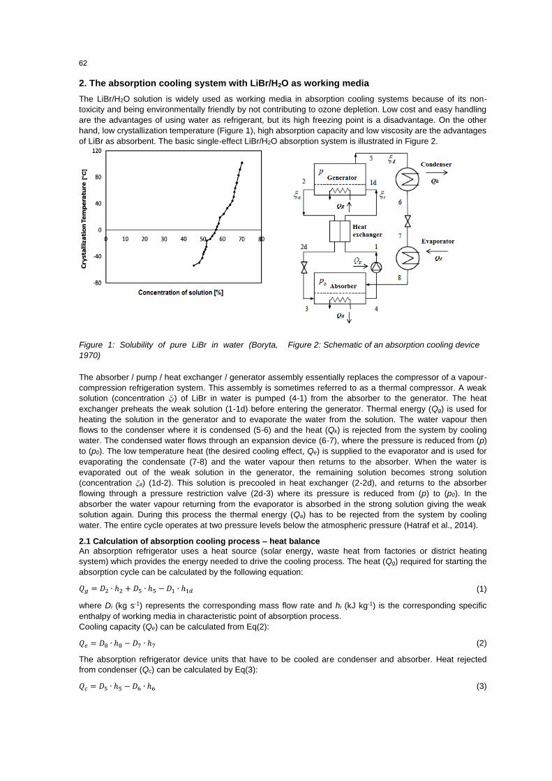
The LiBr/H2O solution is widely used as working media in absorption cooling systems because of its non-
toxicity and being environmentally friendly by not contributing to ozone depletion. Low cost and easy handling
are the advantages of using water as refrigerant, but its high freezing point is a disadvantage. On the other
hand, low crystallization temperature (Figure 1), high absorption capacity and low viscosity are the advantages
of LiBr as absorbent. The basic single-effect LiBr/H2O absorption system is illustrated in Figure 2.
Figure 1: Solubility of pure LiBr in water (Boryta,
1970)
Figure 2: Schematic of an absorption cooling device
The absorber / pump / heat exchanger / generator assembly essentially replaces the compressor of a vapour-
compression refrigeration system. This assembly is sometimes referred to as a thermal compressor. A weak
solution (concentration ξr) of LiBr in water is pumped (4-1) from the absorber to the generator. The heat
exchanger preheats the weak solution (1-1d) before entering the generator. Thermal energy (Qg) is used for
heating the solution in the generator and to evaporate the water from the solution. The water vapour then
flows to the condenser where it is condensed (5-6) and the heat (Qk) is rejected from the system by cooling
water. The condensed water flows through an expansion device (6-7), where the pressure is reduced from (p)
to (p0). The low temperature heat (the desired cooling effect, Qe) is supplied to the evaporator and is used for
evaporating the condensate (7-8) and the water vapour then returns to the absorber. When the water is
evaporated out of the weak solution in the generator, the remaining solution becomes strong solution
(concentration ξa) (1d-2). This solution is precooled in heat exchanger (2-2d), and returns to the absorber
flowing through a pressure restriction valve (2d-3) where its pressure is reduced from (p) to (p0). In the
absorber the water vapour returning from the evaporator is absorbed in the strong solution giving the weak
solution again. During this process the thermal energy (Qa) has to be rejected from the system by cooling
water. The entire cycle operates at two pressure levels below the atmospheric pressure (Hatraf et al., 2014).
2.1 Calculation of absorption cooling process – heat balance
An absorption refrigerator uses a heat source (solar energy, waste heat from factories or district heating
system) which provides the energy needed to drive the cooling process. The heat (Qg) required for starting the
absorption cycle can be calculated by the following equation:
𝑄𝑔 = 𝐷2 ∙ ℎ2 + 𝐷5 ∙ ℎ5 −𝐷1 ∙ ℎ1𝑑 (1)
where Di (kg s-1) represents the corresponding mass flow rate and hi (kJ kg-1) is the corresponding specific
enthalpy of working media in characteristic point of absorption process.
Cooling capacity (Qe) can be calculated from Eq(2):
𝑄𝑒 = 𝐷8 ∙ ℎ8 −𝐷7 ∙ ℎ7 (2)
The absorption refrigerator device units that have to be cooled are condenser and absorber. Heat rejected
from condenser (Qc) can be calculated by Eq(3):
𝑄𝑐 = 𝐷5 ∙ ℎ5 −𝐷6 ∙ ℎ6 (3)
62
Since the absorption of LiBr in water is an exothermic process, heat rejected from the absorber (Qa) can be
calculated from Eq(4):
𝑄𝑎 = 𝐷3 ∙ ℎ3 + 𝐷8 ∙ ℎ8 − 𝐷4 ∙ ℎ4 (4)
The heat exchanged between hot strong solution from generator and cold weak solution from absorber (Qhe)
can be calculated by Eq(5):
𝑄ℎ𝑒 = 𝐷1 ∙ (ℎ1𝑑 − ℎ1) = 𝐷2 ∙ (ℎ2 − ℎ2𝑑) (5)
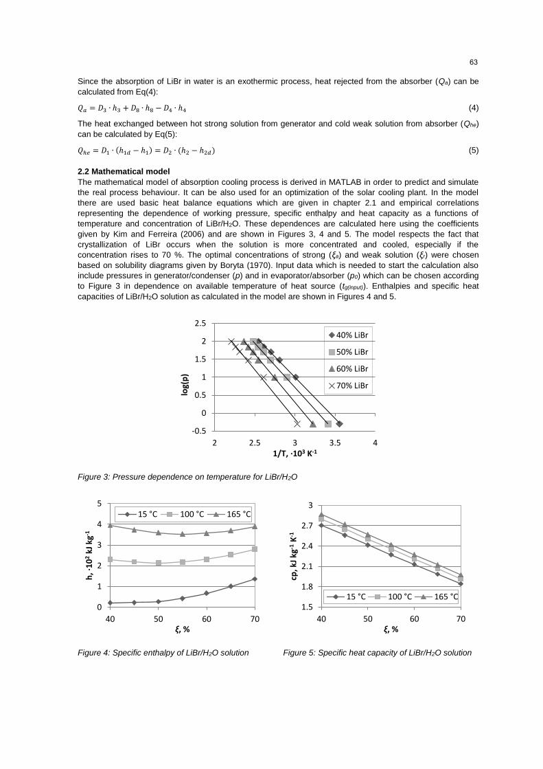
2.2 Mathematical model
The mathematical model of absorption cooling process is derived in MATLAB in order to predict and simulate
the real process behaviour. It can be also used for an optimization of the solar cooling plant. In the model
there are used basic heat balance equations which are given in chapter 2.1 and empirical correlations
representing the dependence of working pressure, specific enthalpy and heat capacity as a functions of
temperature and concentration of LiBr/H2O. These dependences are calculated here using the coefficients
given by Kim and Ferreira (2006) and are shown in Figures 3, 4 and 5. The model respects the fact that
crystallization of LiBr occurs when the solution is more concentrated and cooled, especially if the
concentration rises to 70 %. The optimal concentrations of strong (ξa) and weak solution (ξr) were chosen
based on solubility diagrams given by Boryta (1970). Input data which is needed to start the calculation also
include pressures in generator/condenser (p) and in evaporator/absorber (p0) which can be chosen according
to Figure 3 in dependence on available temperature of heat source (tg(input)). Enthalpies and specific heat
capacities of LiBr/H2O solution as calculated in the model are shown in Figures 4 and 5.
Figure 3: Pressure dependence on temperature for LiBr/H2O
Figure 4: Specific enthalpy of LiBr/H2O solution Figure 5: Specific heat capacity of LiBr/H2O solution
-0.5
0
0.5
1
1.5
2
2.5
2 2.5 3 3.5 4
log(
p)
1/T, ∙103 K-1
40% LiBr
50% LiBr
60% LiBr
70% LiBr
0
1
2
3
4
5
40 50 60 70
h, ∙
10
2kJ
kg-1
ξ, %
15 °C 100 °C 165 °C
1.5
1.8
2.1
2.4
2.7
3
40 50 60 70
cp, k
J kg
-1K
-1
ξ, %
15 °C 100 °C 165 °C
63
3. Solar absorption cooling system in Dubrovnik
The application of solar cooling has become the most discussed application of the absorption cooling
technology. The reason for this is the use of solar radiation as a free and renewable energy source for driving
the process. Therefore this technology acquires the status of ‘Green energy’. Another good circumstance of
this technology is the simultaneous cooling demand and available solar radiation (cooling during the day in
summer). As a case study for this article the solar cooling system installed for the cooling purposes of the
business building of “Vodovod Dubrovnik” in Dubrovnik, Croatia is chosen. The central part of this system
(Figure 6) is the device Yazaki-Maya WFC-SC5 (Tehnokom, 2014).
Figure 6: Process flow diagram of solar cooling system in Dubrovnik
According to the system data, the optimum hot water temperature is 88 °C, and chilled water temperature is
6/12 °C. Installed electric power of the device is 0.05 kW and nominal cooling capacity is 17.6 kW. As the heat
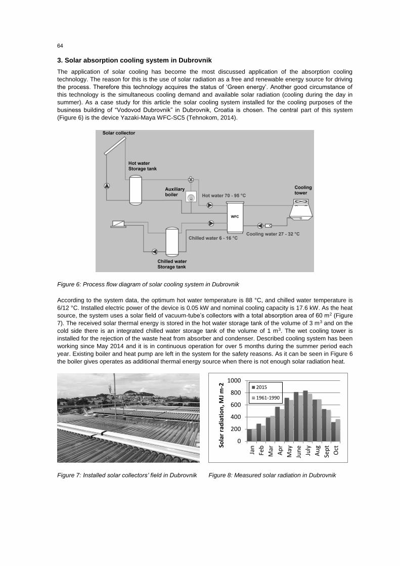
source, the system uses a solar field of vacuum-tube’s collectors with a total absorption area of 60 m2 (Figure
7). The received solar thermal energy is stored in the hot water storage tank of the volume of 3 m3 and on the
cold side there is an integrated chilled water storage tank of the volume of 1 m3. The wet cooling tower is
installed for the rejection of the waste heat from absorber and condenser. Described cooling system has been
working since May 2014 and it is in continuous operation for over 5 months during the summer period each
year. Existing boiler and heat pump are left in the system for the safety reasons. As it can be seen in Figure 6
the boiler gives operates as additional thermal energy source when there is not enough solar radiation heat.
Figure 7: Installed solar collectors’ field in Dubrovnik Figure 8: Measured solar radiation in Dubrovnik
0
200
400
600
800
1000
Jan
Feb
Mar
Ap
r
May
Jun
e
July
Au
g
Sep
t
OctSo
lar
rad
iati
on
, MJ
m-2 2015
1961-1990
64
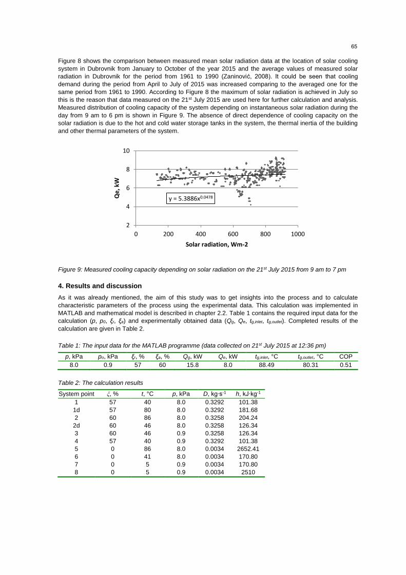
Figure 8 shows the comparison between measured mean solar radiation data at the location of solar cooling
system in Dubrovnik from January to October of the year 2015 and the average values of measured solar
radiation in Dubrovnik for the period from 1961 to 1990 (Zaninović, 2008). It could be seen that cooling
demand during the period from April to July of 2015 was increased comparing to the averaged one for the
same period from 1961 to 1990. According to Figure 8 the maximum of solar radiation is achieved in July so
this is the reason that data measured on the 21st July 2015 are used here for further calculation and analysis.
Measured distribution of cooling capacity of the system depending on instantaneous solar radiation during the
day from 9 am to 6 pm is shown in Figure 9. The absence of direct dependence of cooling capacity on the
solar radiation is due to the hot and cold water storage tanks in the system, the thermal inertia of the building
and other thermal parameters of the system.
Figure 9: Measured cooling capacity depending on solar radiation on the 21st July 2015 from 9 am to 7 pm
4. Results and discussion
As it was already mentioned, the aim of this study was to get insights into the process and to calculate
characteristic parameters of the process using the experimental data. This calculation was implemented in
MATLAB and mathematical model is described in chapter 2.2. Table 1 contains the required input data for the
calculation (p, p0, ξr, ξa) and experimentally obtained data (Qg, Qe, tg,inlet, tg,outlet). Completed results of the
calculation are given in Table 2.
Table 1: The input data for the MATLAB programme (data collected on 21st July 2015 at 12:36 pm)
p, kPa po, kPa ξr, % ξa, % Qg, kW Qe, kW tg,inlet, °C tg,outlet, °C COP
8.0 0.9 57 60 15.8 8.0 88.49 80.31 0.51
Table 2: The calculation results
System point ξ, % t, °C p, kPa D, kg∙s-1 h, kJ∙kg-1
1 57 40 8.0 0.3292 101.38
1d 57 80 8.0 0.3292 181.68
2 60 86 8.0 0.3258 204.24
2d 60 46 8.0 0.3258 126.34
3 60 46 0.9 0.3258 126.34
4 57 40 0.9 0.3292 101.38
5 0 86 8.0 0.0034 2652.41
6 0 41 8.0 0.0034 170.80
7 0 5 0.9 0.0034 170.80
8 0 5 0.9 0.0034 2510
y = 5.3886x0.0478
2
4
6
8
10
0 200 400 600 800 1000
Qe
, kW
Solar radiation, Wm-2
65
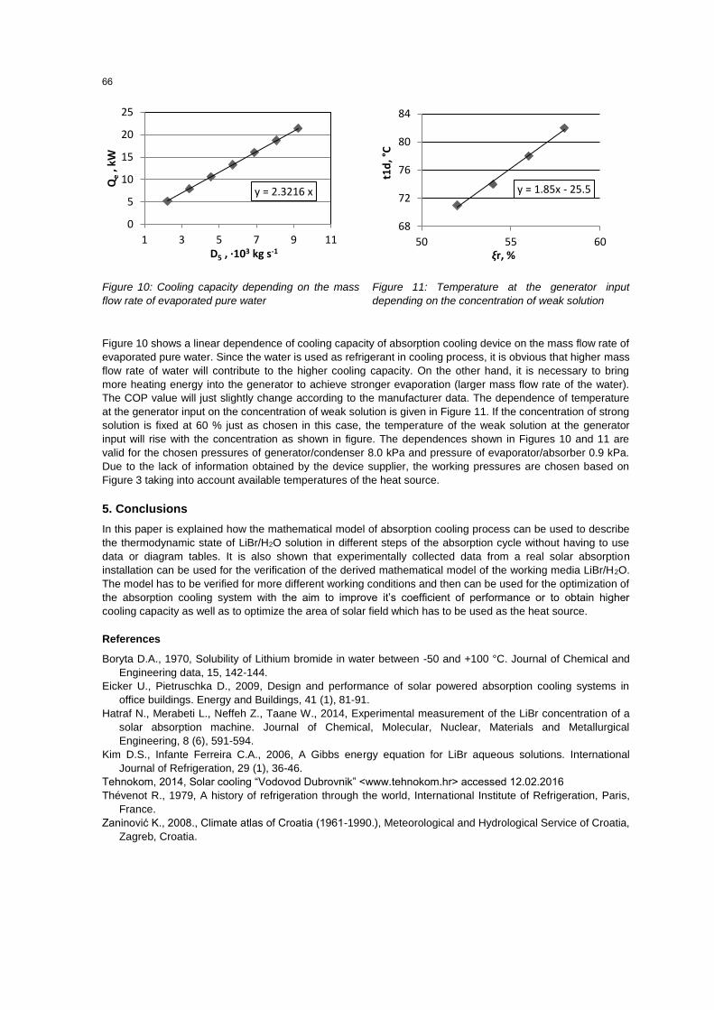
Figure 10: Cooling capacity depending on the mass
flow rate of evaporated pure water
Figure 11: Temperature at the generator input
depending on the concentration of weak solution
Figure 10 shows a linear dependence of cooling capacity of absorption cooling device on the mass flow rate of
evaporated pure water. Since the water is used as refrigerant in cooling process, it is obvious that higher mass
flow rate of water will contribute to the higher cooling capacity. On the other hand, it is necessary to bring
more heating energy into the generator to achieve stronger evaporation (larger mass flow rate of the water).
The COP value will just slightly change according to the manufacturer data. The dependence of temperature
at the generator input on the concentration of weak solution is given in Figure 11. If the concentration of strong
solution is fixed at 60 % just as chosen in this case, the temperature of the weak solution at the generator
input will rise with the concentration as shown in figure. The dependences shown in Figures 10 and 11 are
valid for the chosen pressures of generator/condenser 8.0 kPa and pressure of evaporator/absorber 0.9 kPa.
Due to the lack of information obtained by the device supplier, the working pressures are chosen based on
Figure 3 taking into account available temperatures of the heat source.
5. Conclusions
In this paper is explained how the mathematical model of absorption cooling process can be used to describe
the thermodynamic state of LiBr/H2O solution in different steps of the absorption cycle without having to use
data or diagram tables. It is also shown that experimentally collected data from a real solar absorption
installation can be used for the verification of the derived mathematical model of the working media LiBr/H2O.
The model has to be verified for more different working conditions and then can be used for the optimization of
the absorption cooling system with the aim to improve it’s coefficient of performance or to obtain higher
cooling capacity as well as to optimize the area of solar field which has to be used as the heat source.
References
Boryta D.A., 1970, Solubility of Lithium bromide in water between -50 and +100 °C. Journal of Chemical and
Engineering data, 15, 142-144.
Eicker U., Pietruschka D., 2009, Design and performance of solar powered absorption cooling systems in
office buildings. Energy and Buildings, 41 (1), 81-91.
Hatraf N., Merabeti L., Neffeh Z., Taane W., 2014, Experimental measurement of the LiBr concentration of a
solar absorption machine. Journal of Chemical, Molecular, Nuclear, Materials and Metallurgical
Engineering, 8 (6), 591-594.
Kim D.S., Infante Ferreira C.A., 2006, A Gibbs energy equation for LiBr aqueous solutions. International
Journal of Refrigeration, 29 (1), 36-46.
Tehnokom, 2014, Solar cooling “Vodovod Dubrovnik” <www.tehnokom.hr> accessed 12.02.2016
Thévenot R., 1979, A history of refrigeration through the world, International Institute of Refrigeration, Paris,
France.
Zaninović K., 2008., Climate atlas of Croatia (1961-1990.), Meteorological and Hydrological Service of Croatia,
Zagreb, Croatia.
y = 2.3216 x
0
5
10
15
20
25
1 3 5 7 9 11
Qe
, kW
D5 , ∙103 kg s-1
y = 1.85x - 25.5
68
72
76
80
84
50 55 60
t1d
, °C
ξr, %
66