Embed Size (px)
Citation preview

DS-25-16 Absolute position, rotary Electric Encoder™
1
DS-25-16-2017-01 , DEC 2016
www.netzerprecision.com
The DS-25 is a member of the DS series of Electric Encoders™, based on Netzer Precision proprietary technology. The Electric Encoder™ offers many advantages - some unparalleled
Low profile (7 mm).Hollow, floating shaft. No bearings or other contacting elements.High resolution and precision. High tolerance to temperature extremes , shock, moisture, EMI, RFI and Magnetic fields.Very low weight.Holistic signal generationAnalog or Digital interfaces.
MechanicalAllowable mounting eccentricity ±0.1 mm
Allowable rotor axial motion ±0.1 mm
Rotor inertia 11 gr · mm2
Total weight 4 gr
Outer Ø /Inner Ø/ Height 25 / 6 / 7 mm
The Electric Encoder™ is unique in being holistic, i.e., its output reading is the averaged outcome of the whole area of the rotor , This feature makes the Electric Encoder™ forgiving to mounting tolerances, mechanical wander etc. The absence of components such as ball bearings , flexible couplers, glass disc, light sources and detectors, along with very low power consumption makes the Electric Encoder™ virtually failure free. The internally shielded, DC operated Electric Encoder™ includes an electric field generator, a field receiver, a sinusoidal shaped dielectric rotor, and processing electronics.The output signals of Electric Encoder™ are analog Sine / Cosine representing the rotation angle. The digital outputs are obtained by further processing - which may be either internal or external to the encoder. The combination of precision, low profile, low weight and high reliability have made Netzer Precision encoders particularly suitable to a wide variety of critical applications including, but not limited to medical equipment and aerospace.
Electrical Supply voltage 5V ± 5%
Interconnection Shielded cable or
Cable Length 1,500 mm MAX
EnvironmentalEMC IEC 6100-6-2, IEC 6100-6-4
Operating temperature range Digital: -40°C to +85°C
Relative humidity 98% Non condensing
Shock endurance 100 g for 11 ms
Vibration endurance 20 g 10 – 2000 Hz
Protection IP 40
Characteristics Angular resolution 17 bits ; 131,072 CPR
Static error < 25 mDeg
Maximum operational speed 1,500 rpm
Measurement range Unlimited rotation
Power On - Max. operational speed 3.3 RPM , <=20°/sec
Build In Test BIT Optional

DS-25-16 Absolute position, rotary Electric Encoder™
2
DS-25-16-2017-01 , DEC 2016
www.netzerprecision.com
Description Recommendationsn Total number of data bits 12 - 22T Clock period
f= 1/T Clock frequency 0.5 - 2.0 MHz
Tu Bit update time 200 nsec
Tp Pause time 26 - ∞ μsec
Tm Monoflop time >25 μsec
Tr Time between 2 adjacent requests Tr > n*T+26 μsec
fr=1/Tr Data request frequency
Synchronous Serial Interface (SSI) is a point to point serial interface standard between a master (e.g. controller) and a slave (e.g. sensor) for digital data transmission.
BiSS – C Interface is unidirectional serial synchronous protocol for digital data transmission where the Encoder acts as “slave” transmits data according to “Master” clock. The BiSS protocol is designed in B mode and C mode (continuous mode) .The BiSS-C interface as the SSi is based on RS-422 standards.
SSi / BiSS Output signal parametersSignal latency ~250 μSec
Output code Binary
Serial output Differential RS-422
Clock Differential RS-422
Clock Frequency 0.5 ÷ 2.0 MHz
Position update rate (Max) 30 KHz
Current consumption 180 mA
SSi
Monoflop time 25 μSec
SSi / BiSS interface wires color codeClock + Grey
ClockClock - Blue
Data - YellowData
Data + Green
GND Black Ground
+5V Red Power supply
Software tools: (SSi / BiSS - C)
Advanced calibration and monitoring options are available by using the factory supplied Electric Encoder Explorer software, This facilitates proper mechanical mounting, offsets calibration and advanced signal monitoring.
5V
Host System
CLK / NCP RX [+]
CLK / NCP RX [‐]
5V
5V
120 Ω
(red)
(yellow)
(green)
(blue)
(gray)
(black)
Electric
Encod
er™
Gnd
DATA / NCP TX [‐]
DATA / NCP TX [+]
Digital SSi Interface Digital BiSS-C Interface
bit # Description Default Length
27 AckPeriod during which the encoder calculates the absolute position , one clock cycle
0 1/clock
26 Start Encoder signal for “start” data transmit 1 1 bit
25 “0” “start” bit follower 0 1 bit
8...24 AP Absolute Position encoder data
7 Error Error (amplitude levels) 1 1 bit
6 Warn. Warning (non active) 1 1 bit
0...5 CRC
The CRC polynomial for position, error and warning data is: x6 + x1 + x0. It is transmitted MSB first and inverted.The start bit and “0” bit are omitted from the CRC calculation.
6 bits
Timeout Elapse between the sequential “start”request cycle’s. 25 μs
DS-25-16 Absolute position, rotary Electric Encoder™
3
DS-25-16-2017-01 , DEC 2016
www.netzerprecision.com
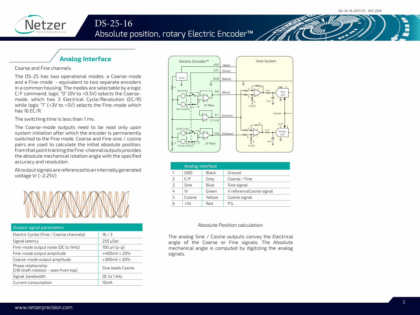
Analog InterfaceCoarse and Fine channels
The DS-25 has two operational modes: a Coarse-mode and a Fine-mode - equivalent to two separate encoders in a common housing. The modes are selectable by a logic C/F command; logic “0” (0V to +0.5V) selects the Coarse-mode, which has 3 Electrical Cycle/Revolution (EC/R) while logic ”1” (+3V to +5V) selects the Fine-mode which has 16 EC/R.
The switching time is less than 1 ms.
The Coarse-mode outputs need to be read only upon system initiation after which the encoder is permanently switched to the Fine mode. Coarse and Fine sine / cosine pairs are used to calculate the initial absolute position, from that point tracking the Fine-channel outputs provides the absolute mechanical rotation angle with the specified accuracy and resolution.
All output signals are referenced to an internally generated voltage Vr (~2.25V)
Output signal parameters Electric Cycles (Fine / Coarse channels) 16 / 3
Signal latency 250 μSec
Fine-mode output noise (DC to 1kHz) 100 μV (p-p)
Fine-mode output amplitude ±400mV ± 20%
Coarse-mode output amplitude ±300mV ± 20%
Phase relationship (CW shaft rotation - seen from top) Sine leads Cosine
Signal bandwidth DC to 1 kHz
Current consumption 10mA
Cos
Sin+
‐
+5V
C/F
Gnd
Vr
Host System Electric Encoder™
+
‐
Sample
+‐
+
‐
SINE (COARSE)
+‐
SINE (FINE)
COSINE (COARSE)
COSINE (FINE)
(Red)
(Yellow)
(Green)
(Blue)
(Grey)
(Black)
R
R
(~2.2V)
+4.5V
CosineA/D
LP filter
LP filter
Sine A/D
R1
R2
10nF
R1R2
4.7K
R2
R1
R2
R1
4.7K
10nF
Vref
Vref
Vref/2
Vref/2
Absolute Position calculation:
The analog Sine / Cosine outputs convey the Electrical angle of the Coarse or Fine signals. The Absolute mechanical angle is computed by digitizing the analog signals.
Analog interface 1 GND Black Ground
2 C/F Grey Coarse / Fine
3 Sine Blue Sine signal
4 Vr Green V referenceCosine signal
5 Cosine Yellow Cosine signal
6 +5V Red P.S.

DS-25-16 Absolute position, rotary Electric Encoder™
4
DS-25-16-2017-01 , DEC 2016
www.netzerprecision.com
Pair # Color123
Red / BlackGray / Blue
Green / Yellow
30 AWG twisted pairs (3)
Braided shield
Jacket 0.45mm
3.45 ± 0.20mm
30 AWG single insulated wire0.017
Ø 0.61 ± 0.051mm
Netzer Cat No.: CB-00014Provider: Ray-Q USA. wire CAT No: RQ213210Cable: 30 AWG twisted pair (3) :2 (30 AWG 25/44 finned copper , 0.15 PFE to Ø0.6 ± 0.05 OD).Temperature rating: -60 to +150 Deg C. Braided shield: Thinned copper braided 95% min. coverage. Jacket: 0.45 silicon rubber jacket Ø3.45 ±0.2 OD Related documents:
DS-25 User Manual : Mechanical , Electrical and calibration setup.
Demonstration Kit:
DS-25DKIT-01: Includes ,mounted encoder on rotary jig , and RS-422 to USB converter.
DS Product line
Outputs:
D - Digital : SSi E - Digital : BiSS-C 0 - Analog 1 Vp-p
Interconnection:
S - Shielded cable 250 mm (default)
C - Encapsulated external module
ResolutionCode Bit CPR
F 17 131,072
DS -
C - Connector (optional) 0 - Flying leads (default) B - Rotor metal sleeve
nnn - Custom
Outer Diameter
Fine ECR
25 - 16 - - S -0 n n nFD
SC2SSi External module
250 mm
SC2SSi External Encapsulated module
250 mm
Shielded cable AWG30
Analog Output
Digital Output SSi / BiSS-C
Teflon insulated AWG32
Shielded cable AWG30
BIT (Build In Test): optional
[ ] - none B - BIT
Dimensions on page # 8

DS-25-16 Absolute position, rotary Electric Encoder™
5
DS-25-16-2017-01 , DEC 2016
www.netzerprecision.com
3 SLOTS FOR ENCODERCLAMP EQ.SP
MOUNTING SURFACE
-
1
5.60
0.300
2 PL
AC
ES8
1.50
+ 7
0.05
0.02
0.70
25+ 7.
352
PLA
CES
6+0.02
0
A
A DS-25 ICDDS-25-16-00-S0DS-25-16-DF-S0DS-25-16-EF-S0
DS-25-16 Absolute position, rotary Electric Encoder™
6
DS-25-16-2017-01 , DEC 2016
www.netzerprecision.com
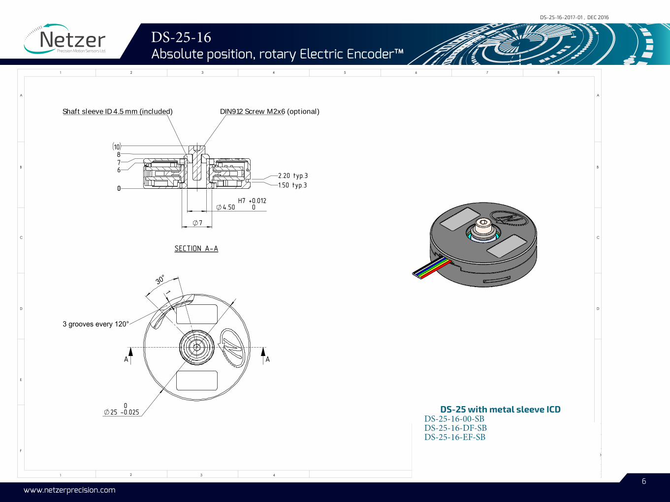
25 -00.025
1
30°
AA
3 grooves every 120°
4.50 H7
+ 0.0120
7
00 1.50 typ.32.20 typ.3
6
SECTION A-A
D
E
F
C
1 2 3 4
C
D
1 2 3 4 5 6 7 8
A A
Shaft sleeve ID 4.5 mm (included) DIN912 Screw M2x6 (optional)
1087
B B
The information contaned in this drawing is the sole property ot Netzer Precision Motion Sensores Ltd. Any reproduction in part or whole without the written permission of Netzer Precision Motion Sensors Ltd.is prohibited. The drawing is confidential,and is the property of Netzer Precision Ltd. it must not be disclosed to a third party without written consent of Netzer Precision Ltd.
SIGNATURE
DS-25-16-DF-SB, ID 4.5 mm11-12-1611-12-16
Jacob H.Jacob H.
11-12-16Michael A.
DS-25-16-DF-SB-ICD A3SHEET 1 OF 1
SCALE: 3:1DWG NO. :
TITLE:
MATERIAL:
DATENAME
UNLESS OTHERWISE SPECIFIED:DIMENSIONS ARE IN mmSURFACE FINISH: N6LINEAR TOLERANCES: 0.1 mmANGULAR TOLERANCES: 0.5 degALL CHAMFER: 0.1 mm X 45°
APPV'DCHK'DDRAWN
Coating:
CAT NO. : 00Revision :
DS-25-16-DF-SB-ICD
DS-25 with metal sleeve ICDDS-25-16-00-SBDS-25-16-DF-SBDS-25-16-EF-SB

DS-25-16 Absolute position, rotary Electric Encoder™
7
DS-25-16-2017-01 , DEC 2016
www.netzerprecision.com
DETAIL B SCALE 4 : 1
*
0.5
0min
1 1.4
0 -0 0.
05
0.5
0
2
13
4
B
B
C0.02
SECTION D-D
A0.02 B
0.02
0.02
A
0.05 A
C
0
23
0.5
0 m
in
*
1.4
0 ±0
.05
0.20 X 45°
0.05
0.02
0.07++
25 *
6 -
5.60
3HOLES #0-80" EQ.SP.
28
A A
0.1 A
SECTION A-A
B
16
* 0
-0.057.30
M3 6
Shaft - End installation (step) No Part Description QTY.
1 DS-25-16 Included DS-25 encoder 1
2 EAPK004 Included Kit Kit , 3 x Encoder clamps ULTEM 13
MA-DS25-004 OptionalShaft End installation kit
Washer DIN125-A3.2 14 Screw DIN 7984 M3x5 1
Critical dimensions marked with “*”

DS-25-16 Absolute position, rotary Electric Encoder™
8
DS-25-16-2017-01 , DEC 2016
www.netzerprecision.com
3
4
1
4
32
SECTION A-A
B
0 * -0.05
16
7.30
M3 6
DETAIL B SCALE 4 : 1
*
0.5
0min
0.10
1.5
0 RE
F
0 - 5
.50
1.4
0 -0 0.
05
0.5
0
3 HOLES M2 EQ.SP.
29.80
A A
0.1 A
B0.02
0.02 C
A
B
A0.1
SECTION C-C
0.05
B
A
0.02
0.05 A
C
*
0.070.05*
00.02
0.20 X 45°
25.50
++
25
23
00.50
+ 1
6 -
5.60
Deep , Shaft - End installation (step) No Part Description QTY.
1 DS-25-16 Included DS-25 encoder 1
2 EAPK005 Included Kit Kit , 3 x Encoder clamps St.St. 13
MA-DS25-004 OptionalShaft End installation kit
Washer DIN125-A3.2 14 Screw DIN 7984 M3x5 1
Critical dimensions marked with “*”

DS-25-16 Absolute position, rotary Electric Encoder™
9
DS-25-16-2017-01 , DEC 2016
www.netzerprecision.com
SC2SSi , DS-25 external digital module (SSi/BiSS) Part Description QTY.SC2SSi-03 Included with DS-25 CAT No. 1