Embed Size (px)
Citation preview
ABRHS PHYSICS (CP) NAME: ____________________ Chapters 35: Electric Circuits
2014-15
Text: Chapter 35 Think and Explain: 1-10 Think and Solve: 1-4 Vocabulary: ammeter, voltmeter, series, parallel, equivalent resistance, circuit, short circuit, open circuit Equations:
Req = R1 + R2 +
1Req
=1R1
+1R2
+
I = Qt
V = IR P = IV qPEV e= P = PEe
t Q = ne
Constants: e = 1.6 x 10⁻¹⁹ C Key Objectives: Concepts ! explain what happens to current and voltage in series and parallel circuits. ! correctly interpret a circuit diagram. ! correctly use ammeters and voltmeters in a circuit. (Lab Practical!) ! compare and contrast an ammeter and a voltmeter. ! apply the law of conservation of charge to a circuit (i.e. what happens to current in a circuit) ! apply the law of conservation of energy to a circuit. (i.e. what happens to voltage in a circuit) ! given a circuit made of identical light bulbs, be able to predict the relative brightness of each
bulb and what would happen if bulbs were unscrewed or shorted. ! explain how the outlets in your home are connected and why. Problem Solving ! solve for the missing variable in Ohm’s Law. ! calculate the equivalent resistance for resistors connected in series or parallel. ! calculate the missing variables (V, I, R) for a series, parallel or compound circuit.


ABRHS PHYSICS (CP) NAME: _______________
Lab 35-1: Series Circuits
side 1
Purpose: 1. To calculate the voltages and currents for individual resistors in a series circuit.
2. To calculate the equivalent resistance of a series circuit. 3. To determine what happens to voltage, current and resistance in a series
circuit. Equipment: 7 wires 6 alligator clips one 5-! & two 2-! resistors 1 ammeter 1 voltmeter 1 power supply Procedure: Circuit 1: Two resistors in series.
1. Hook up the circuit shown in the diagram below. 2. Set the power supply for 1 volt. DON'T CHANGE IT ONCE IT IS SET. 3. Measure the current and voltage for the 2 ! resistor and record in the data table
below the diagram. 4. Repeat measurements for the 5 ! resistor. 5. Measure the total voltage and total current using your portable meters. (This makes
sure you use the same devices to measure all the currents and voltages.)
Circuit 2: Three resistors in series. 1. Hook up the circuit shown in the diagram below. 2. Repeat your procedure from Part I, recording your results in the data table below the
diagram.
Remember: Ammeters are connected in series. Voltmeters are connected in parallel.
Diagrams: Circuit 1 Circuit 2
2 Ω 5 Ω
2 Ω 5 Ω 2 Ω
Data:
Circuit 1 Circuit 2 R V I R V I
2 Ω 2 Ω
5 Ω 5 Ω
2 Ω
Vpower supply Vpower supply Ipower supply Ipower supply
ABRHS PHYSICS (CP) NAME: _______________
Lab 35-1: Series Circuits
side 2
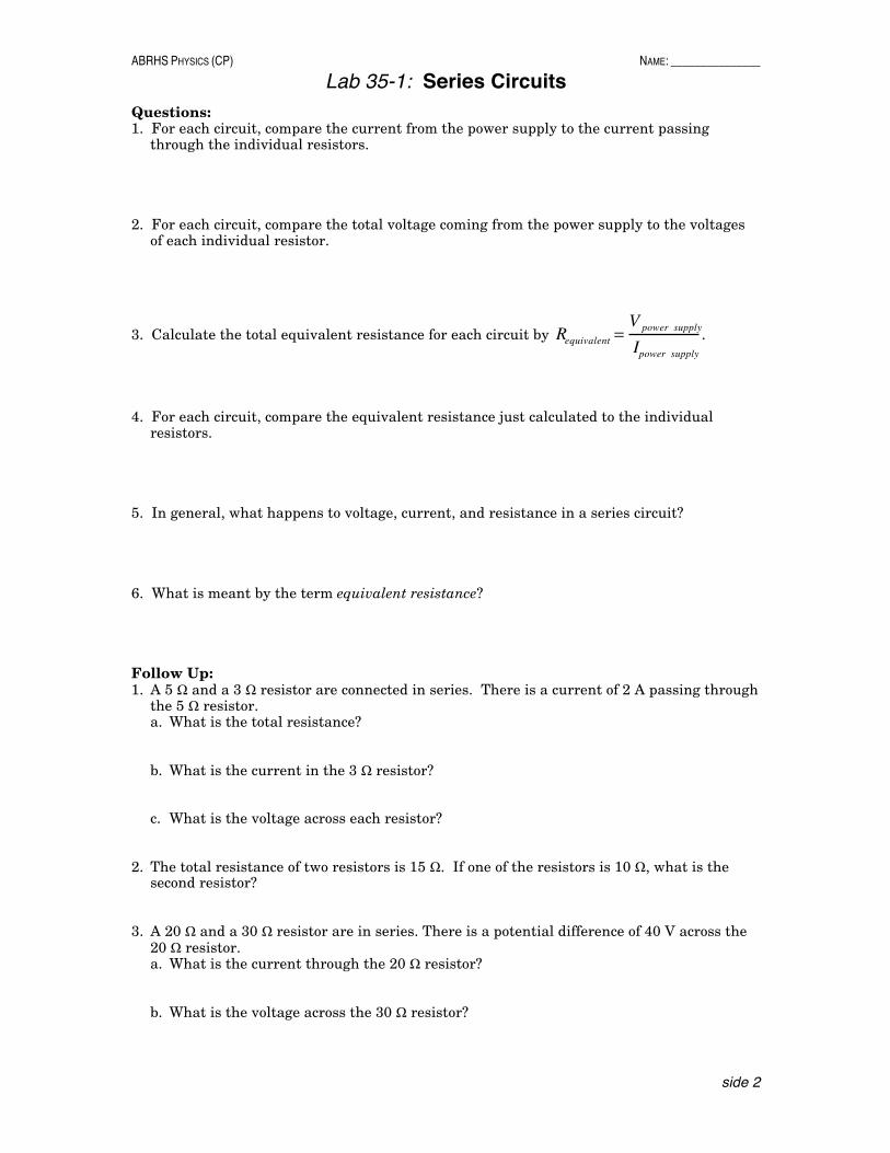
Questions: 1. For each circuit, compare the current from the power supply to the current passing
through the individual resistors. 2. For each circuit, compare the total voltage coming from the power supply to the voltages
of each individual resistor.
3. Calculate the total equivalent resistance for each circuit by Requivalent =V power supply
Ipower supply
.
4. For each circuit, compare the equivalent resistance just calculated to the individual
resistors. 5. In general, what happens to voltage, current, and resistance in a series circuit? 6. What is meant by the term equivalent resistance? Follow Up: 1. A 5 ! and a 3 ! resistor are connected in series. There is a current of 2 A passing through
the 5 ! resistor. a. What is the total resistance? b. What is the current in the 3 ! resistor? c. What is the voltage across each resistor?
2. The total resistance of two resistors is 15 !. If one of the resistors is 10 !, what is the
second resistor? 3. A 20 ! and a 30 ! resistor are in series. There is a potential difference of 40 V across the
20 ! resistor. a. What is the current through the 20 ! resistor? b. What is the voltage across the 30 ! resistor?

ABRHS PHYSICS NAME: _________________
Series Circuits
side 1
The following problems are all based on the following series circuit. For each problem, find all the missing numbers.
R1 R2 R3
Vtotal
Circuit 1
R I V R1 3 Ω Vt = 9 V
R2 3 Ω It =
R3 3 Ω Rt = Circuit 2
R I V R1 12 Ω Vt =
R2 12 Ω It = 2 A
R3 12 Ω Rt = Circuit 3
R I V R1 4 Ω Vt = 9 V
R2 8 Ω It =
R3 6 Ω Rt = Circuit 4
R I V R1 6 Ω Vt =
R2 12 Ω It = 3 A
R3 Rt = 20 Ω

ABRHS PHYSICS NAME: _________________
Series Circuits
side 2
R1 R2 R3
Vtotal
Circuit 5
R I V R1 4 Ω Vt = 12 V
R2 1 A It =
R3 5 V Rt = Circuit 6
R I V R1 0.5 A Vt = 11 V
R2 4 V It =
R3 6 V Rt = Circuit 7
R I V R1 2 V Vt =
R2 10 V It = 2 A
R3 3 Ω Rt = 9 Ω Circuit 8
R I V R1 8 Ω Vt =
R2 It = 3 A
R3 12 V Rt = 20 Ω

ABRHS PHYSICS (CP) NAME: _______________
Lab 35-2: Parallel Circuits
side 1
Purpose: 1. To calculate the voltages and currents for individual resistors in a parallel circuit.
2. To calculate the equivalent resistance of a parallel circuit. 3. To determine what happens to voltage, current and resistance in a parallel
circuit. Equipment: 7 wires 6 alligator clips one 5-! & two 2-! resistors 1 ammeter 1 voltmeter 1 power supply Procedure: Circuit 1: Two resistors in parallel.
1. Hook up the circuit shown in the diagram below. 2. Set the power supply for 1 volt. DON'T CHANGE IT ONCE IT IS SET. 3. Measure the current and voltage for the 3 ! resistor and record in the data table
below the diagram. 4. Repeat measurements for the 5 ! resistor. 5. Measure the total voltage and total current using your portable meters. (This makes
sure you use the same devices to measure all the currents and voltages.)
Circuit 2: Three resistors in parallel. 1. Hook up the circuit shown in the diagram below. 2. Repeat your procedure from Part I, recording your results in the data table below the
diagram.
Remember: Ammeters are connected in series. Voltmeters are connected in parallel.
Diagrams: Circuit 1 Circuit 2
2 Ω 5 Ω
2 Ω 5 Ω 2 Ω
Data:
Circuit 1 Circuit 2 R V I R V I
2 Ω 2 Ω
5 Ω 5 Ω
2 Ω
Vpower supply Vpower supply
Ipower supply Ipower supply

ABRHS PHYSICS (CP) NAME: _______________
Lab 35-2: Parallel Circuits
side 2
Questions: 1. For each circuit, compare the current from the power supply to the current passing
through the individual resistors. 2. For each circuit, compare the total voltage coming from the power supply to the voltages
of each individual resistor.
3. Calculate the total equivalent resistance for each circuit by Requivalent =V power supply
Ipower supply
.
4. For each circuit, compare the equivalent resistance just calculated to the individual
resistors.
5. With calculations, show that
1Requivalent
=1R1
+1R2
+1R3
+! in a parallel circuit.
6. In general, what happens to voltage, current, and resistance in a parallel circuit? Follow Up: 1. A 4 ! and a 4 ! resistor are connected in parallel. What is their total resistance? 2. A 3 ! and a 6 ! resistor are connected in parallel. What is their total resistance? 3. What is the total resistance of three 2-! resistors connected in parallel? 4. Two identical resistors are connected in parallel and have a total resistance of 4 !. What
are the individual resistors?

ABRHS PHYSICS (CP) NAME: _________________
Parallel Circuits
side 1
The following problems are all based on the following parallel circuit. For each problem, find all the missing numbers.
R1 R2 R3Vtotal
Circuit 1
R I V
R1 3 Ω Vtotal = 9 V
R2 3 Ω Itotal =
R3 3 Ω Rtotal = Circuit 2
R I V
R1 12 Ω 0.5 A Vtotal =
R2 12 Ω Itotal =
R3 12 Ω Rtotal = Circuit 3
R I V R1 6 Ω Vtotal = 6 V
R2 12 Ω Itotal =
R3 3 Ω Rtotal = Circuit 4
R I V R1 6 Ω Vtotal = 12 V
R2 12 Ω Itotal = 6 A
R3 Rtotal =

ABRHS PHYSICS (CP) NAME: _________________
Parallel Circuits
side 2
R1 R2 R3Vtotal
Circuit 5
R I V R1 10 Ω Vtotal =
R2 Itotal =
R3 20 Ω 1 A Rtotal = 5 Ω Circuit 6
R I V R1 0.5
A Vtotal =
R2 Itotal = 3 A
R3 1 A Rtotal = 2 Ω Circuit 7
R I V R1 2 A Vtotal =
R2 2 Ω 3 A Itotal =
R3 5 A Rtotal = Circuit 8
R I V R1 8 Ω Vtotal =
R2 2 A Itotal = 4 A
R3 Rtotal = 1 Ω
ABRHS PHYSICS (CP) NAME: __________________
Series & Parallel Circuits
side 1
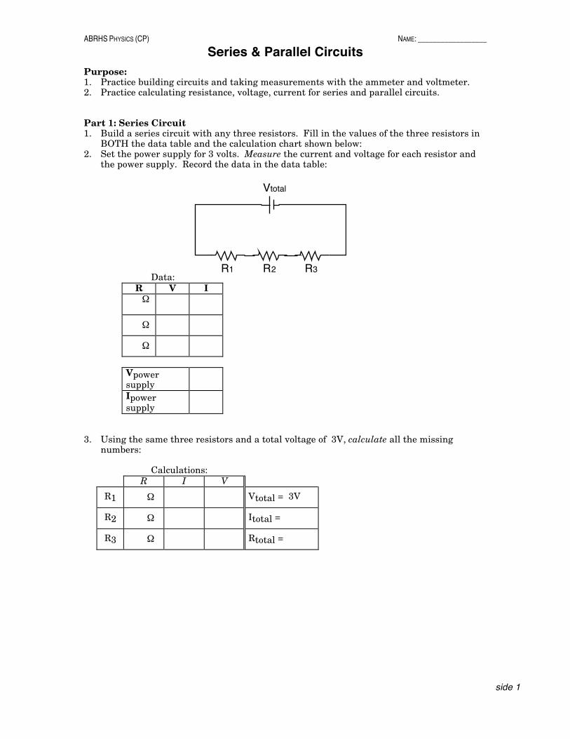
Purpose: 1. Practice building circuits and taking measurements with the ammeter and voltmeter. 2. Practice calculating resistance, voltage, current for series and parallel circuits. Part 1: Series Circuit 1. Build a series circuit with any three resistors. Fill in the values of the three resistors in
BOTH the data table and the calculation chart shown below: 2. Set the power supply for 3 volts. Measure the current and voltage for each resistor and
the power supply. Record the data in the data table: Data:
R V I Ω
Ω
Ω
Vpower supply
Ipower supply
3. Using the same three resistors and a total voltage of 3V, calculate all the missing
numbers: Calculations:
R I V
R1 Ω Vtotal = 3V
R2 Ω Itotal =
R3 Ω Rtotal =
R1 R2 R3
Vtotal

ABRHS PHYSICS (CP) NAME: _______________
Lab 35-3: Compound Circuits
side 1
Purpose: 1. To calculate the voltages and currents for individual resistors in a compound circuit.
2. To calculate the actual equivalent resistance of a compound circuit. 3. To calculate the ideal equivalent resistance of a compound circuit. 4. To determine what happens to voltage, current and resistance in a compound
circuit. 5. To apply the ideas of conservation of charge and conservation of energy to a
compound circuit. Procedure:
1. Hook up the circuit shown in the diagram below. 2. Set the power supply for about 1 volt. 3. Measure the current and voltage for each resistor in the circuit and record in the data
table. 4. Measure the total voltage and total current using your portable meters.
Remember: Ammeters are connected in series. Voltmeters are connected in parallel.
Circuit 1 Diagram:
Vtotal
R1
R2
R3
Data:
R V I R1 2 Ω
R2 5 Ω
R3 2 Ω
Vpower supply
Ipower supply
Questions: 1. The current in R1 should have been the same as the current leaving the power supply.
Why? 2. The current going through R1 should have been equal to the sum of the current in R2 and
R3. Why? 3. The voltages of two resistors should be the same. Which two are they and why should
they be the same?
ABRHS PHYSICS (CP) NAME: _______________
Lab 35-3: Compound Circuits
side 2
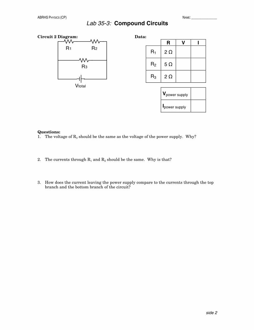
Circuit 2 Diagram:
Vtotal
R1 R2
R3
Data:
R V I R1 2 Ω
R2 5 Ω
R3 2 Ω
Vpower supply
Ipower supply
Questions: 1. The voltage of R3 should be the same as the voltage of the power supply. Why? 2. The currents through R1 and R2 should be the same. Why is that? 3. How does the current leaving the power supply compare to the currents through the top
branch and the bottom branch of the circuit?

ABRHS PHYSICS NAME: ____________________ Circuit Analysis
side 1
It turns out that one can understand an analyze even the most complicated circuits by just remembering one equation and two simple rules: 1) Ohm's Law, 2) charge is conserved and 3) energy is conserved. It's really that simple!
Ohm's Law The fundamental equation behind circuit analysis is Ohm's Law, or
V=IR You can think of it as a "cause and effect" equation. If there is a voltage (V) across a resistor (R) then a current (I) will flow. (It is sort of like F=ma.) While voltage is actually energy per charge, you can think of it as a sort of electrical push trying to get electrons to flow through a resistor. No push, no flow. The "Junction Rule" aka Conservation of Charge A junction is anyplace a wire branches off into 2 or more different wires or 2 or more wires come together into a single wire. One of the fundamental ideas in physics is that electric charge must be conserved. In circuit analysis, this means that electrons cannot be created or destroyed while they move through the circuit. Therefore, the total current going into a junction has to equal the total current going out of a junction. (You can think of the electrons as cars, and the wires as roads - every car that enters an intersection leaves the intersection.) 1. What is meant by the word junction in a circuit? 2. What is the Junction Rule? 3. The Junction Rule is really just a statement of what basic principle? 4. What could be the unmarked current in the pictures below?
10 A 10 A
8 A
x 5 A 3 A
x
7 A z
y
4 A
1 A
x
5. When resistors are connected in series, what must be true about the currents through each of the
resistors? 6. When resistors are connected in parallel, what must be true about the currents through each of
the resistors?

ABRHS PHYSICS NAME: ____________________ Circuit Analysis
side 2
The "Loop Rule" aka Conservation of Energy A loop is just any closed path that an electron might take in the circuit. We will keep the circuits fairly simple and not do multiple voltage sources, so for us, this simply means what are the possible ways that an electron might take to go from one terminal of the power supply to the other. (In college, you will probably see problems with multiple power supplies, but we won't do that.) Another fundamental idea in physics is that energy must be conserved. In a circuit, a battery gives electrons energy. The electrons use that energy in going through resistors. (We are assuming ideal wires with no resistance.) Because energy can't be created or destroyed, the total energy "used up" by an electron going through a circuit must be the same as the total energy given the electron by the power supply. Since voltage is simply energy per charge, this also means that the voltage of the power supply has to equal the sum of the voltages of all the resistors that the electron went through. 1. Where does an electron get the energy to move through a circuit? 2. Where does an electron lose energy in a circuit? 3. What happens to the energy lost by an electron going through a resistor? 4. What is the Loop Rule? 5. The Loop Rule is really just a statement of what basic principle? 6. For each of the circuits shown below, sketch in the two possible paths (loops) that an electron
could make in going from one terminal of the power supply to the other. (For our purposes, it doesn't matter if you go clockwise or counter clockwise.)
Vtotal
R1
R2
R3
Vtotal
R1 R2
R3 R4

ABRHS PHYSICS (CP) NAME: _________________
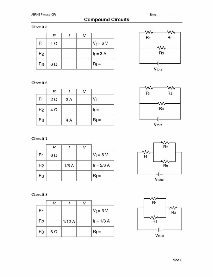
Compound Circuits
side 1
Fill in the missing information for each of the given circuits Circuit 1
R I V
R1 2 Ω 1 A Vt =
R2 It =
R3 2 Ω 3 A Rt =
Circuit 2
R I V
R1 4 Ω Vt = 12 V
R2 4 V It =
R3 4 Ω Rt = Circuit 3
R I V
R1 3 Ω Vt = 12 V
R2 6 Ω It =
R3 6 Ω Rt = Circuit 4
R I V
R1 4 Ω Vt =
R2 8 V It = 3 A
R3 4 V Rt =
Vtotal
R1
R2
R3
Vtotal
R1
R2
R3
Vtotal
R1
R2
R3
Vtotal
R1
R2
R3
ABRHS PHYSICS (CP) NAME: _________________
Compound Circuits
side 2
Circuit 5
R I V
R1 1 Ω Vt = 6 V
R2 It = 3 A
R3 6 Ω Rt =
Circuit 6
R I V
R1 2 Ω 2 A Vt =
R2 4 Ω It =
R3 4 A Rt =
Circuit 7
R I V
R1 6 Ω Vt = 6 V
R2 1/6 A It = 2/3 A
R3 Rt =
Circuit 8
R I V
R1 Vt = 3 V
R2 1/12 A It = 1/3 A
R3 6 Ω Rt =
Vtotal
R1
R2
R3
Vtotal
R1 R2
R3
Vtotal
R1 R2
R3
Vtotal
R1
R2
R3

ABRHS PHYSICS (CP) NAME: __________________
Lab 35-4: Light Bulb Circuits
side 1
Purpose: 1. To develop a conceptual understanding of basic circuits. 2. To define the terms series circuit, parallel circuit, short circuit, and open circuit. Materials:
3 light bulbs & holders 2 ammeters 1 voltmeter 6 alligator clips 10 wires
Procedure: You will be asked to make several simple circuits and alter them a number of times. Each time, record your observations of all the light bulbs and any meters that you are using. Be very careful to note whenever something changes. Make note of the brightness of the bulbs and any meter readings. Part I: Series Circuits 1. Hook up a light bulb and ammeter as shown in the diagram. Adjust the power supply until the
light bulb is bright. Record the current passing through the light bulb.
A
2. Unscrew the light bulb. What happens to the bulb and the current? 3. Screw the bulb back in. Without adjusting the power supply, add a second light bulb to your
circuit as shown. What happens to the brightness of the bulbs and the current?
A
4. Unscrew one of the light bulbs. What happens? 5. Screw the bulb back in. Remove the ammeter and connect it so that it is in between the two light
bulbs. What happens?
A
6. Put the ammeter back to where it started. Adjust the power supply until both light bulbs are as
bright as the first one was. Record the current passing through the bulbs. 7. Add a third light bulb to your circuit. What happens to the brightness of the bulbs and the
current?
A

ABRHS PHYSICS (CP) NAME: __________________
Lab 35-4: Light Bulb Circuits
side 2
8. Unscrew one of the light bulbs. What happens? 9. Screw the bulb back in. Unscrew a different bulb. What happens? 10. Screw the bulb back in. Take a wire and connect it around a light bulb as shown. What happens
to the brightness of each bulb and the current?
A
11. Repeat step 10 by short circuiting the other two bulbs, one at a time. NOTE: do not short out
the entire circuit! 12. Take a second ammeter and connect around a light bulb, as you did with the wire in step 10.
What happens to the brightness of each bulb and the current?
A
A
13. Remove the ammeter from the circuit. With a voltmeter, record the total voltage for your circuit. 14. Connect the voltmeter as shown in the diagram. What happens to the brightness of each bulb
and the readings on the ammeter and voltmeter?
A
V
Part II: Parallel Circuits 1. Hook up a light bulb and ammeter as shown in the diagram. Adjust the power supply until the
light bulb is bright. Record the current passing through the light bulb.
A
2. Without adjusting the power supply, add a second light bulb to your circuit as shown. What
happens to the brightness of the bulbs and the current?
A

ABRHS PHYSICS (CP) NAME: __________________
Lab 35-4: Light Bulb Circuits
side 3
3. Unscrew one of the light bulbs. What happens? 4. Screw the bulb back in. Unscrew the other light bulb. What happens? 5. Add a third light bulb as shown. What happens?
A
6. One at a time, unscrew each light bulb. What happens? 7. Make sure all the bulbs are lit. Take a wire and briefly connect it around one of the bulbs as
shown in the diagram. What happens?
A
8. Repeat step 7 with the other two bulbs. Questions: 1. Define the following terms:
series circuit parallel circuit short circuit open circuit
2. Which would be brighter, a light bulb with more current passing through it or less current? 3. Which meter acts like a short circuit? 4. Which meter acts like an open circuit? 5. If you were to keep the power supply set to the same voltage all the time and kept adding light
bulbs in series, what would happen to the brightness of the light bulbs? What would happen to the total current leaving the power supply?
6. If you were to keep the power supply set to the same voltage all the time and kept adding light
bulbs in parallel, what would happen to the brightness of the light bulbs? What would happen to the total current leaving the power supply?

ABRHS PHYSICS (CP) NAME: ____________________ Light Bulb Circuits
For each circuit, use 3 identical light bulbs and make the circuit shown. For each question, predict what will happen, and then test it on your circuit. Circuit 1 1. Rank the brightness of the bulbs, from brightest to dimmest. 2. What happens to the brightness of each bulb if you
a. unscrew bulb A? b. unscrew bulb B? c. unscrew bulb C?
3. What happens to the brightness of each bulb if you
a. short out bulb A? b. short out bulb B? c. short out bulb C?
Circuit 2 4. Rank the brightness of the bulbs, from brightest to
dimmest. 5. What happens to the brightness of each bulb if you
a. unscrew bulb A? b. unscrew bulb B? c. unscrew bulb C?
6. What happens to the brightness of each bulb if you
a. short out bulb A? b. short out bulb B? c. short out bulb C?
A
B
C
A B
C

ABRHS PHYSICS (CP) NAME: _________________
More Circuit Problems
side 1
Fill in the missing information for each of the given circuits Circuit 1
R I V
R1 2 Ω Vt =
R2 0.5 A It =
R3 3 Ω Rt = 7 Ω
Circuit 2
R I V
R1 5 Ω Vt = 20 V
R2 4 Ω It =
R3 1 Ω Rt = Circuit 3
R I V
R1 3 Ω Vt = 12 V
R2 6 Ω It =
R3 3 Ω Rt = Circuit 4
R I V
R1 2 Ω 2 A Vt =
R2 It = 7 A
R3 4 Ω Rt =
R1 R2 R3
Vtotal
R1 R2 R3
Vtotal
R1 R2 R3Vtotal
R1 R2 R3Vtotal

ABRHS PHYSICS (CP) NAME: _________________
More Circuit Problems
side 2
Circuit 5
R I V
R1 Vt = 5 V
R2 2 Ω It = 3 A
R3 0.5 A Rt =
Circuit 6
R I V
R1 3 A 6 V Vt =
R2 2 Ω It =
R3 1.5 A Rt =
Circuit 7
R I V
R1 1 Ω 2 A Vt =
R2 It =
R3 5 Ω 1 A Rt =
Circuit 8
R I V
R1 6 A Vt =
R2 It = 9 A
R3 36 V Rt = 10 Ω
Vtotal
R1
R2
R3
Vtotal
R1
R2 R3
Vtotal
R1
R2
R3
Vtotal
R1 R2
R3
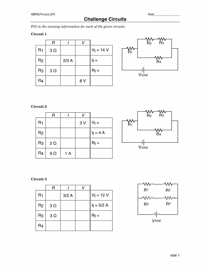
ABRHS PHYSICS (CP) NAME: _________________
Challenge Circuits
side 1
Fill in the missing information for each of the given circuits Circuit 1
R I V
R1 3 Ω Vt = 14 V
R2 2/3 A It =
R3 3 Ω Rt =
R4 8 V
Circuit 2
R I V
R1 3 V Vt =
R2 It = 4 A
R3 2 Ω Rt =
R4 9 Ω 1 A Circuit 3
R I V
R1 3/2 A Vt = 12 V
R2 3 Ω It = 5/2 A
R3 3 Ω Rt =
R4
Vtotal
R1
R2 R3
R4
Vtotal
R1
R2 R3
R4
Vtotal
R1 R2
R3 R4

ABRHS PHYSICS (CP) NAME: _________________
Challenge Circuits
side 2
Circuit 4
R I V
R1 8 V Vt =
R2 16 V It = 6 A
R3 2 Ω Rt =
R4 4 Ω
Circuit 5
R I V
R1 Vt = 36 V
R2 1 A It = 6 A
R3 3 Ω 2 A Rt =
R4
R5 2 A
R6 8 V
R7 1 Ω
R8 18 V
Vtotal
R1 R2
R3 R4
Vtotal
R1
R2
R3R4
R5 R6R7
R8