Embed Size (px)
Citation preview
NORTH DAKOTA AGRICULTURAL EXPERIMENT STATION 31
Above Ground Pump Houses' By John Gar land 2 and Richard L. Witz5
Water systems 011 the farm may be installed in several loca-tions. However, sanitary regulations do not permit an installation in any location without a positive (gravity) drain. In many loca-tions this will not allow the system to be installed in the house base-ment or in a well pit.
During the past year several installations have been made us-ing insulated pump houses built above the ground. This allows the pump house to be built over the well, which, if centrally located, will reduce the cost of piping as compared with a basement loca-tion. At the same time the pumping equipment is not subjected to the moisture present in well pits.
If the power supply to the pump is connected to the line ahead of the yard disconnect switch, a water supply is available in case of fire. This is not true of basement installations since the power supply will have to be disconnected at the yard pole.
During the winter of 1949-50, four above ground pump houses were under observation and records taken on electrical consump-tion for supplementary heating.
Considerable heat is obtained from the water in passing through the pressure tank. However, this supply of heat, which varies from day to day and farm to farm) cannot be depended on to heat the pump house. Additional heat, usually in the form of light bulbs or heat lamps, is necessary. These should be connected to a reliable thermostat set at around 35 °F. All of these pump houses have six inches of insulation in the walls and roof and are built on a concrete slab.
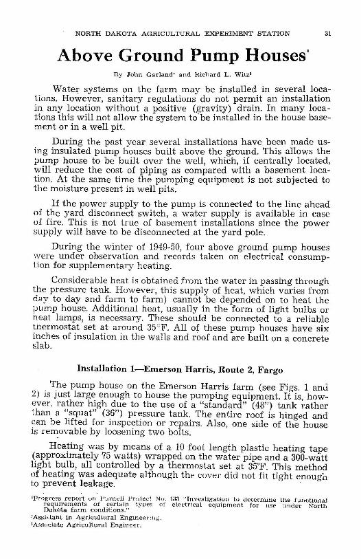
Installation 1—Emerson Harris, Route 2, Fargo The pump house on the Emerson Harris farm (see Figs. 1 and
2) is just large enough to house the pumping equipment. It is, how-ever, rather high due to the use of a "standard" (48") tank rather than a "squat" (36") pressure tank. The entire roof is hinged and can be lifted for inspection or repairs. Also, one side of the house is removable by loosening two bolts.
Heating was by means of a 10 foot length plastic heating tape (approximately 75 watts) wrapped on the water pipe and a 300-watt light bulb, all controlled by a thermostat set at 35°F. This method of heating was adequate although the cover did not fit tight enough to prevent leakage.
«Progress report un I 'urnel i Project No. 133 ' Inves t iga t ion to de t e rmine the funct ional r equ i rement s of certain types of electrical equ ipment for use under North Dakota f a r m condit ions."
^Assistant in Agr icul tura l Engineer ing. 'Associate Agr icul tura l Engineer .
••'A BIMONTHLY BULLETIN, VOLUME XIII , NO. 1, SEPT.-OCT., 1950
Fig. 1—Harris farm pump house showing straw banking. Fig. Z—Same pump house as Fig. 1
with banking removed.
• „ nA 3 / % i n l h drain extends through the side wall and is too small
be adequate ^ ^ A ^ a b ° U t 1 / 4 i n c h e s i n diameter wSSd
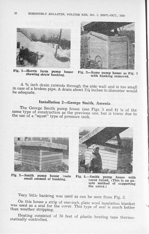
Installation 2—George Smith, Amenia
s a r n ^ L G e ° / g e S , m i t i - p u m p 1
h o u s e ( s e e F iS s- 3 a n d 4) is of the t h f n t y p f « construction as the previous one, but is lower due to the use of a "squat" type of pressure tank.
Fig. 3—Smith pump house (note Fig. 4.—Smith pumu house with small amount of banking. c o v e r raiseTP(This is an un
safe method of supporting the cover.)
Very little banking was used as can be seen from Fig. 3.
w a ^ V ^ L ^ T i V t r i £ 0 f one" inr£1
h S l a s s- wool insulation blanket than l e a t h e r stripping. ^ T h l S t y P e ° f ^ ÌS ™ c h
s t a t i ^ l y ^ c o n t r o l l ^ d . e ( ^ ° f 1 0 f e e t ° f p l a s t i c t a p e t h —
NORTH DAKOTA AGRICULTURAL EXPERIMENT STATION 33
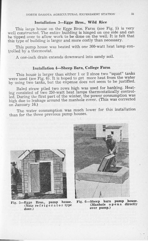
Installation 3—Egge Bros., Wild Rice This large house on the Egge Bros. Farm (see Fig. 5) is very
well constructed. The entire building is hinged on one side and can be tipped over to allow work to be done on the well. It is felt that this type of building is larger and more costly than necessary.
This pump house was heated with one 300-watt heat lamp con-trolled by a thermostat.
A one-inch drain extends downward into sandy soil.
Installation 4—Sheep Barn, College Farm This house is larger than either 1 or 2 since two "squat" tanks
were used (see Fig. 6). It is hoped to get more heat from the water by using two tanks, but the expense does not seem to be justified.
Baled straw piled two rows high was used for banking. Heat-ing consisted of two 250-watt heat lamps thermostatically control-led During the first part of the winter, the power consumption was high due to leakage around the manhole cover. (This was corrected on January 16.)
The water consumption was much lower for this installation than for the three previous pump houses.
Fig. 6—Sheep barn pump house. (Manhole o p e n s directly over pump.)
Fig. 5—Egge Bros., pump house. (Note r e f r i g e r a t o r type door.)
••'A BIMONTHLY BULLETIN, VOLUME XIII, NO. 1, SEPT.-OCT., 1950
Table 1. POWER CONSUMPTION FOR HEATING
Ave. Outside Energy Installation Time Temperature Consumption Remarks
No. Month "F Kwh/month " 1 Jan. -7.1 i s 2 Feb "5 8 8 Ave. of Jan. & Feb.
I f e b ' 5.8 16 No records taken in Jan. ~ H 1 0 4 * Consumption Jan. 16-31
^ M 5 29 kwh.
+ S e ™ a I f ? n s u T r £ - l o n J , a j ? u a r y U 1 Q w a s high due to air leakage a r o ^ d the cover. Also, additional heat was used on one occasion to thaw out the pump. (Pump froze due to the thermostat failing to operate.)
Summary 1. The house should be just large enough to house the equipment
using a "squat" type tank, and insulated with six inches of in-sulation.
2. The entire cover should be hinged or the house easily moved to allow work on the well. The cover need not extend over the walls as much as shown in Figs. 1 and 2.
3. Heat must be supplied. The use of two lamps of about 150 watts each would be adequate providing the house is well built. These should be connected to a reliable thermostat set at about 35 °F.
4. The cover should fit tightly. The method used in Installation .Number 1 is quite good.
5. A saving in heating and additional protection in case of an elec-trical outtage can be effected by banking the house with loose straw.
6. On hinged covers a permanent support, not easily dislodged, should be used to prevent accidents while the cover is open.
NEW INFORMATION ON NEMATODES
Every agricultural worker knows about nematodes, and the damage they do to crops. Only a handful of scientists in the whole country. are working on this enemy of agriculture, but they have made a lot of head-way in recent years. The latest news is that all root-knot nematodes do not belong to one species, as commonly believed, but that at least 5 separate species have been identified. There may be many others. The clue to this discovery was provided by experiments on host plants. A study of mor-phological structures confirmed the belief that different species exist A basic discovery of this kind may not seem important to the layman, but it was just such a discovery by a Department entomologist several years ago that led to the successful control of screw worms in cattle—USDA Agri-cultural Research Administration.


![IT CAME UPON A MIDNIGHT CLEAR - Bytown · Web viewLittle Drummer Boy [D] Come they told me, Pa [A7] rup a pum [D] pum [D] A new born king to see. Pa [A7] rup a pum [D] pum [A] Our](https://img.pdfslide.us/doc/110x75/5a7098a47f8b9aa2538c3b0a/docit-came-upon-a-midnight-clear-bytown-ukulelewwwbytownukulelecaportalsukuleleclubsongsweb.jpg)