Embed Size (px)
Citation preview
i
About the Tutorial
Internet Protocol version 4 (IPv4) is the fourth version in the development of the
Internet Protocol (IP) and the first version of the protocol to be widely deployed.
IPv4 is described in IETF publication RFC 791 (September 1981), replacing an
earlier definition (RFC 760, January 1980).
This tutorial will help you in understanding IPv4 and its associated terminologies
along with appropriate references and examples.
Audience
This tutorial has been designed to help beginners understand basic concepts of
IPv4 required to work with any TCP/IP based protocols. After completing this
tutorial, you will find yourself at a moderate level of expertise of IPv4 from
where you can take yourself to next levels.
Prerequisites
Before you start proceeding with this tutorial, I'm making an assumption that
you are already aware of basic computer and network concepts such as what is a
protocol, why do we need protocol, Network Layers, etc.
Copyright & Disclaimer
Copyright 2014 by Tutorials Point (I) Pvt. Ltd.
All the content and graphics published in this e-book are the property of
Tutorials Point (I) Pvt. Ltd. The user of this e-book is prohibited to reuse, retain,
copy, distribute or republish any contents or a part of contents of this e-book in
any manner without written consent of the publisher.
We strive to update the contents of our website and tutorials as timely and as
precisely as possible, however, the contents may contain inaccuracies or errors.
Tutorials Point (I) Pvt. Ltd. provides no guarantee regarding the accuracy,
timeliness or completeness of our website or its contents including this tutorial.
If you discover any errors on our website or in this tutorial, please notify us at
ii
Table of Contents
About the Tutorial ....................................................................................................................................... i
Audience ..................................................................................................................................................... i
Prerequisites ............................................................................................................................................... i
Copyright & Disclaimer ................................................................................................................................ i
Table of Contents ....................................................................................................................................... ii
1. OVERVIEW .............................................................................................................................. 1
What is Network? ....................................................................................................................................... 1
Host Addressing .......................................................................................................................................... 2
2. THE OSI MODEL....................................................................................................................... 3
Network Layer ............................................................................................................................................ 4
3. THE TCP/IP MODEL ................................................................................................................. 5
Internet Protocol Version 4 (IPv4)............................................................................................................... 5
4. PACKET STRUCTURE ................................................................................................................ 7
5. ADDRESSING ........................................................................................................................... 9
Unicast Addressing Mode ........................................................................................................................... 9
Broadcast Addressing Mode ....................................................................................................................... 9
Multicast Addressing Mode ...................................................................................................................... 10
Hierarchical Addressing Scheme ............................................................................................................... 11
Subnet Mask ............................................................................................................................................. 11
Binary Representation .............................................................................................................................. 12
6. ADDRESS CLASSES ................................................................................................................. 14
Class A Address ......................................................................................................................................... 14
Class B Address ......................................................................................................................................... 15
Class C Address ......................................................................................................................................... 15
iii
Class D Address ......................................................................................................................................... 15
Class E Address ......................................................................................................................................... 16
7. SUBNETTING ......................................................................................................................... 17
Class A Subnets ......................................................................................................................................... 17
Class B Subnets ......................................................................................................................................... 18
Class C Subnets ......................................................................................................................................... 19
8. VLSM ..................................................................................................................................... 20
Step - 1 ..................................................................................................................................................... 20
Step - 2 ..................................................................................................................................................... 20
Step - 3 ..................................................................................................................................................... 21
Step - 4 ..................................................................................................................................................... 21
Step - 5 ..................................................................................................................................................... 21
Step - 6 ..................................................................................................................................................... 21
9. RESERVED ADDRESSES .......................................................................................................... 22
Private IP Addresses ................................................................................................................................. 22
Loopback IP Addresses ............................................................................................................................. 22
Link-local Addresses ................................................................................................................................. 23
10. EXAMPLE ............................................................................................................................. 24
Packet Flow in Network ............................................................................................................................ 24
Step 1 – Acquiring an IP Address (DHCP) ................................................................................................... 25
Step 2 – DNS Query .................................................................................................................................. 25
Step 3 – ARP Request ................................................................................................................................ 25
11. SUMMARY ........................................................................................................................... 27
Internet Protocol v6 (IPv6) ........................................................................................................................ 27
Ipv4
1
This era is said to be the era of computers. Computers have significantly
changed the way we live. A computing device when connected to other
computing device(s) enables us to share data and information at lightning fast
speed.
What is Network?
A Network in the world of computers is said to be a collection of interconnected
hosts, via some shared media which can be wired or wireless. A computer
network enables its hosts to share and exchange data and information over the
media. Network can be a Local Area Network spanned across an office or Metro
Area Network spanned across a city or Wide Area Network which can be spanned
across cities and provinces.
A computer network can be as simple as two PCs connected together via a single
copper cable or it can be grown up to the complexity where every computer in
this world is connected to every other, called the Internet. A network then
includes more and more components to reach its ultimate goal of data
exchange. Below is a brief description of the components involved in computer
network:
Hosts - Hosts are said to be situated at ultimate end of the network, i.e. a
host is a source of information and another host will be the destination.
Information flows end to end between hosts. A host can be a user’s PC, an
internet Server, a database server etc.
Media - If wired, then it can be copper cable, fiber optic cable, and
coaxial cable. If wireless, it can be free-to-air radio frequency or some
special wireless band. Wireless frequencies can be used to interconnect
remote sites too.
Hub - A hub is a multiport repeater and it is used to connect hosts in a
LAN segment. Because of low throughputs hubs are now rarely used. Hub
works on Layer-1 (Physical Layer) of OSI Model.
Switch - A Switch is a multiport bridge and is used to connect hosts in a
LAN segment. Switches are much faster than Hubs and operate on wire
speed. Switch works on Layer-2 (Data Link Layer), but Layer-3 (Network
Layer) switches are also available.
Router - A router is Layer-3 (Network Layer) device which makes routing
decisions for the data/information sent for some remote destination.
Routers make the core of any interconnected network and the Internet.
1. OVERVIEW
Ipv4
2
Gateways - A software or combination of software and hardware put
together, works for exchanging data among networks which are using
different protocols for sharing data.
Firewall - Software or combination of software and hardware, used to
protect users’ data from unintended recipients on the network/internet.
All components in a network ultimately serve the hosts.
Host Addressing
Communication between hosts can happen only if they can identify each other
on the network. In a single collision domain (where every packet sent on the
segment by one host is heard by every other host) hosts can communicate
directly via MAC address.
MAC address is a factory coded 48-bits hardware address which can also
uniquely identify a host. But if a host wants to communicate with a remote host,
i.e. not in the same segment or logically not connected, then some means of
addressing is required to identify the remote host uniquely. A logical address is
given to all hosts connected to Internet and this logical address is
called Internet Protocol Address.
Ipv4
3
The International Standard Organization has a well-defined model for
Communication Systems known as Open System Interconnection, or the OSI
Model. This layered model is a conceptualized view of how one system should
communicate with the other, using various protocols defined in each layer.
Further, each layer is designated to a well-defined part of communication
system. For example, the Physical layer defines all the components of physical
nature, i.e. wires, frequencies, pulse codes, voltage transmission etc. of a
communication system.
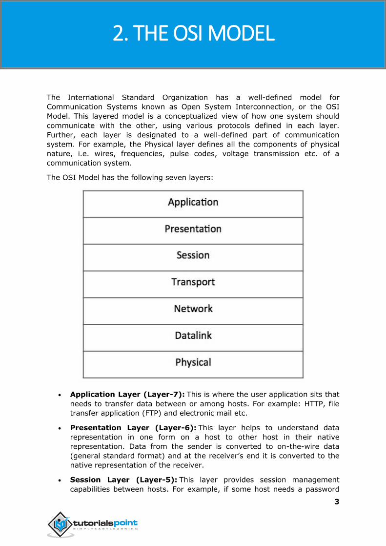
The OSI Model has the following seven layers:
Application Layer (Layer-7): This is where the user application sits that
needs to transfer data between or among hosts. For example: HTTP, file
transfer application (FTP) and electronic mail etc.
Presentation Layer (Layer-6): This layer helps to understand data
representation in one form on a host to other host in their native
representation. Data from the sender is converted to on-the-wire data
(general standard format) and at the receiver’s end it is converted to the
native representation of the receiver.
Session Layer (Layer-5): This layer provides session management
capabilities between hosts. For example, if some host needs a password
2. THE OSI MODEL
Ipv4
4
verification for access and if credentials are provided then for that session
password verification does not happen again. This layer can assist in
synchronization, dialog control and critical operation management (e.g.,
an online bank transaction).
Transport Layer (Layer-4): This layer provides end-to-end data delivery
among hosts. This layer takes data from the above layer and breaks it
into smaller units called Segments and then gives it to the Network layer
for transmission.
Network Layer (Layer-3): This layer helps to uniquely identify hosts
beyond the subnets and defines the path which the packets will follow or
be routed to reach the destination.
Data Link Layer (Layer-2): This layer takes the raw transmission data
(signal, pulses, etc.) from the Physical Layer and makes Data Frames, and
sends that to the upper layer and vice versa. This layer also checks any
transmission errors and sorts it out accordingly.
Physical Layer (Layer-1): This layer deals with hardware technology
and actual communication mechanism such as signaling, voltage, cable
type and length, etc.
Network Layer
The network layer is responsible for carrying data from one host to another. It
provides means to allocate logical addresses to hosts, and identify them
uniquely using the same. Network layer takes data units from Transport Layer
and cuts them into smaller unit called Data Packet.
Network layer defines the data path, the packets should follow to reach the
destination. Routers work on this layer and provides mechanism to route data to
its destination.
Ipv4
5
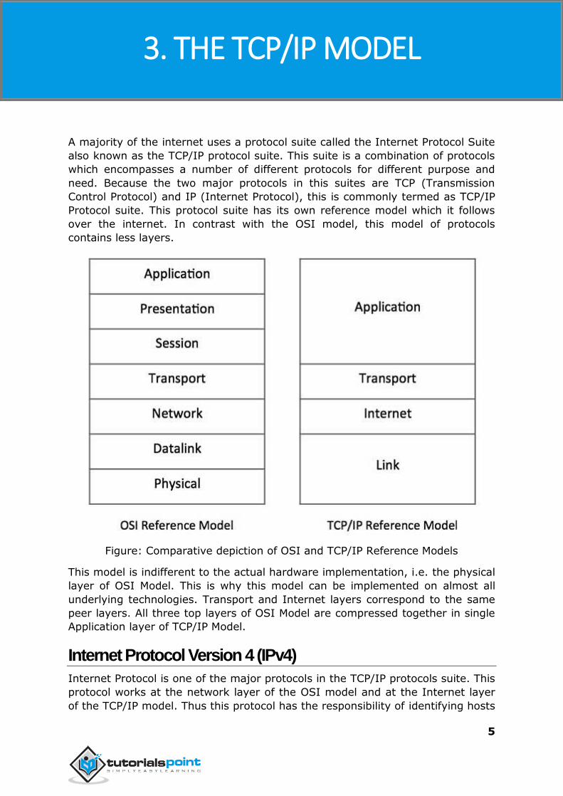
A majority of the internet uses a protocol suite called the Internet Protocol Suite
also known as the TCP/IP protocol suite. This suite is a combination of protocols
which encompasses a number of different protocols for different purpose and
need. Because the two major protocols in this suites are TCP (Transmission
Control Protocol) and IP (Internet Protocol), this is commonly termed as TCP/IP
Protocol suite. This protocol suite has its own reference model which it follows
over the internet. In contrast with the OSI model, this model of protocols
contains less layers.
Figure: Comparative depiction of OSI and TCP/IP Reference Models
This model is indifferent to the actual hardware implementation, i.e. the physical
layer of OSI Model. This is why this model can be implemented on almost all
underlying technologies. Transport and Internet layers correspond to the same
peer layers. All three top layers of OSI Model are compressed together in single
Application layer of TCP/IP Model.
Internet Protocol Version 4 (IPv4)
Internet Protocol is one of the major protocols in the TCP/IP protocols suite. This
protocol works at the network layer of the OSI model and at the Internet layer
of the TCP/IP model. Thus this protocol has the responsibility of identifying hosts
3. THE TCP/IP MODEL
Ipv4
6
based upon their logical addresses and to route data among them over the
underlying network.
IP provides a mechanism to uniquely identify hosts by an IP addressing scheme.
IP uses best effort delivery, i.e. it does not guarantee that packets would be
delivered to the destined host, but it will do its best to reach the destination.
Internet Protocol version 4 uses 32-bit logical address.
Ipv4
7
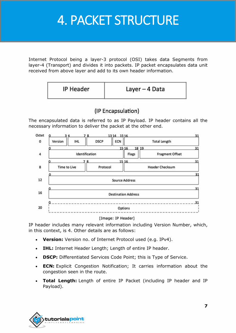
Internet Protocol being a layer-3 protocol (OSI) takes data Segments from
layer-4 (Transport) and divides it into packets. IP packet encapsulates data unit
received from above layer and add to its own header information.
The encapsulated data is referred to as IP Payload. IP header contains all the
necessary information to deliver the packet at the other end.
IP header includes many relevant information including Version Number, which,
in this context, is 4. Other details are as follows:
Version: Version no. of Internet Protocol used (e.g. IPv4).
IHL: Internet Header Length; Length of entire IP header.
DSCP: Differentiated Services Code Point; this is Type of Service.
ECN: Explicit Congestion Notification; It carries information about the
congestion seen in the route.
Total Length: Length of entire IP Packet (including IP header and IP
Payload).
4. PACKET STRUCTURE
Ipv4
8
Identification: If IP packet is fragmented during the transmission, all the
fragments contain same identification number to identify original IP
packet they belong to.
Flags: As required by the network resources, if IP Packet is too large to
handle, these ‘flags’ tell if they can be fragmented or not. In this 3-bit
flag, the MSB is always set to ‘0’.
Fragment Offset: This offset tells the exact position of the fragment in
the original IP Packet.
Time to Live: To avoid looping in the network, every packet is sent with
some TTL value set, which tells the network how many routers (hops) this
packet can cross. At each hop, its value is decremented by one and when
the value reaches zero, the packet is discarded.
Protocol: Tells the Network layer at the destination host, to which
Protocol this packet belongs to, i.e. the next level Protocol. For example
protocol number of ICMP is 1, TCP is 6 and UDP is 17.
Header Checksum: This field is used to keep checksum value of entire
header which is then used to check if the packet is received error-free.
Source Address: 32-bit address of the Sender (or source) of the packet.
Destination Address: 32-bit address of the Receiver (or destination) of
the packet.
Options: This is optional field, which is used if the value of IHL is greater
than 5. These options may contain values for options such as Security,
Record Route, Time Stamp, etc.
Ipv4
9
IPv4 supports three different types of addressing modes.
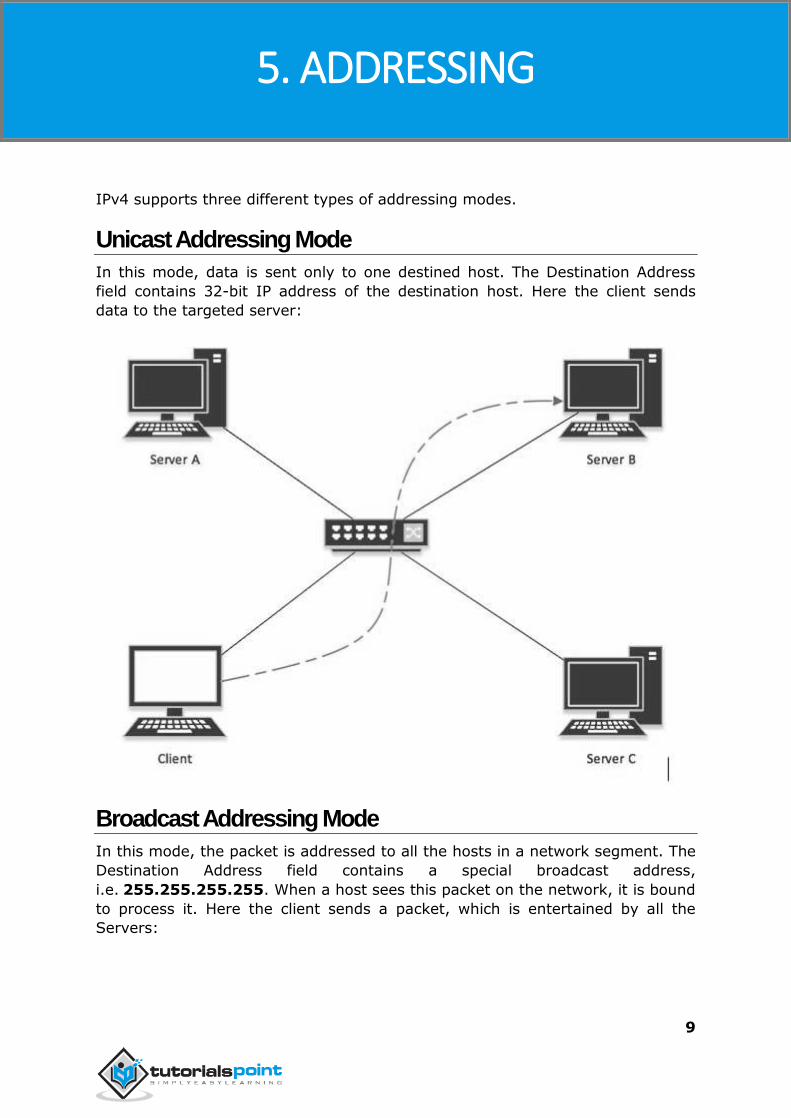
Unicast Addressing Mode
In this mode, data is sent only to one destined host. The Destination Address
field contains 32-bit IP address of the destination host. Here the client sends
data to the targeted server:
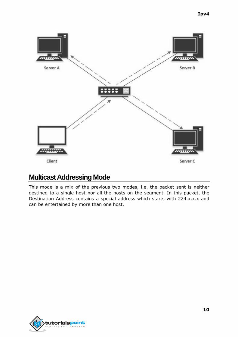
Broadcast Addressing Mode
In this mode, the packet is addressed to all the hosts in a network segment. The
Destination Address field contains a special broadcast address,
i.e. 255.255.255.255. When a host sees this packet on the network, it is bound
to process it. Here the client sends a packet, which is entertained by all the
Servers:
5. ADDRESSING
Ipv4
10
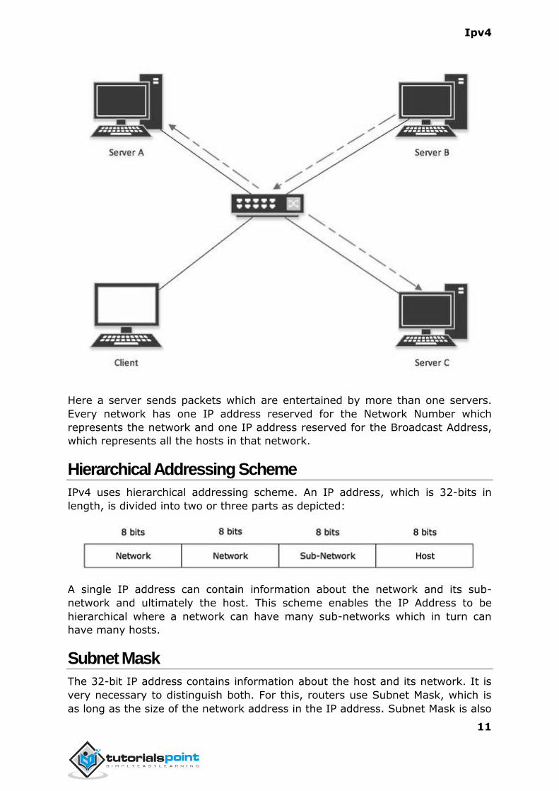
Multicast Addressing Mode
This mode is a mix of the previous two modes, i.e. the packet sent is neither
destined to a single host nor all the hosts on the segment. In this packet, the
Destination Address contains a special address which starts with 224.x.x.x and
can be entertained by more than one host.
Ipv4
11
Here a server sends packets which are entertained by more than one servers.
Every network has one IP address reserved for the Network Number which
represents the network and one IP address reserved for the Broadcast Address,
which represents all the hosts in that network.
Hierarchical Addressing Scheme
IPv4 uses hierarchical addressing scheme. An IP address, which is 32-bits in
length, is divided into two or three parts as depicted:
A single IP address can contain information about the network and its sub-
network and ultimately the host. This scheme enables the IP Address to be
hierarchical where a network can have many sub-networks which in turn can
have many hosts.
Subnet Mask
The 32-bit IP address contains information about the host and its network. It is
very necessary to distinguish both. For this, routers use Subnet Mask, which is
as long as the size of the network address in the IP address. Subnet Mask is also
Ipv4
12
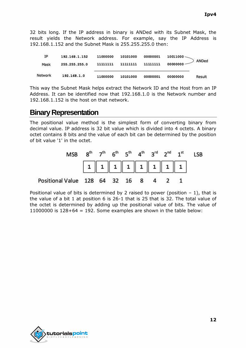
32 bits long. If the IP address in binary is ANDed with its Subnet Mask, the
result yields the Network address. For example, say the IP Address is
192.168.1.152 and the Subnet Mask is 255.255.255.0 then:
This way the Subnet Mask helps extract the Network ID and the Host from an IP
Address. It can be identified now that 192.168.1.0 is the Network number and
192.168.1.152 is the host on that network.
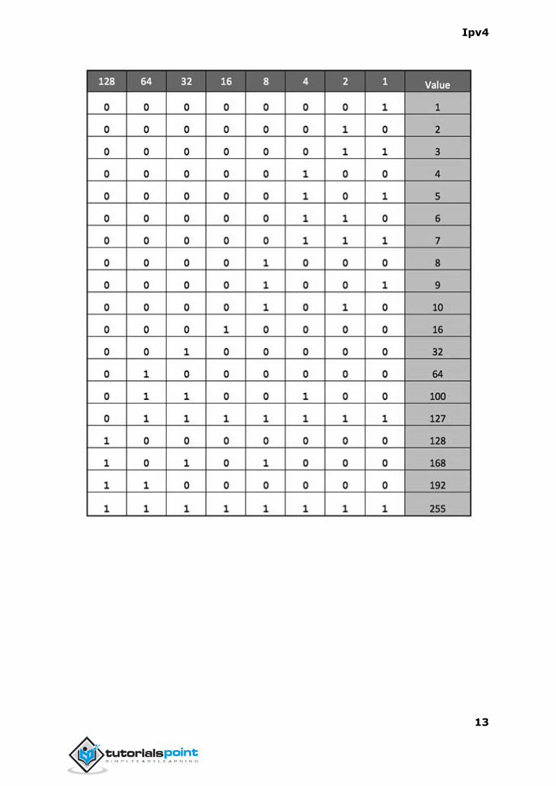
Binary Representation
The positional value method is the simplest form of converting binary from
decimal value. IP address is 32 bit value which is divided into 4 octets. A binary
octet contains 8 bits and the value of each bit can be determined by the position
of bit value '1' in the octet.
Positional value of bits is determined by 2 raised to power (position – 1), that is
the value of a bit 1 at position 6 is 26-1 that is 25 that is 32. The total value of
the octet is determined by adding up the positional value of bits. The value of
11000000 is 128+64 = 192. Some examples are shown in the table below:
Ipv4
13
Ipv4
14
Internet Protocol hierarchy contains several classes of IP Addresses to be used
efficiently in various situations as per the requirement of hosts per network.
Broadly, the IPv4 Addressing system is divided into five classes of IP Addresses.
All the five classes are identified by the first octet of IP Address.
The Internet Corporation for Assigned Names and Numbers is responsible for
assigning IP addresses.
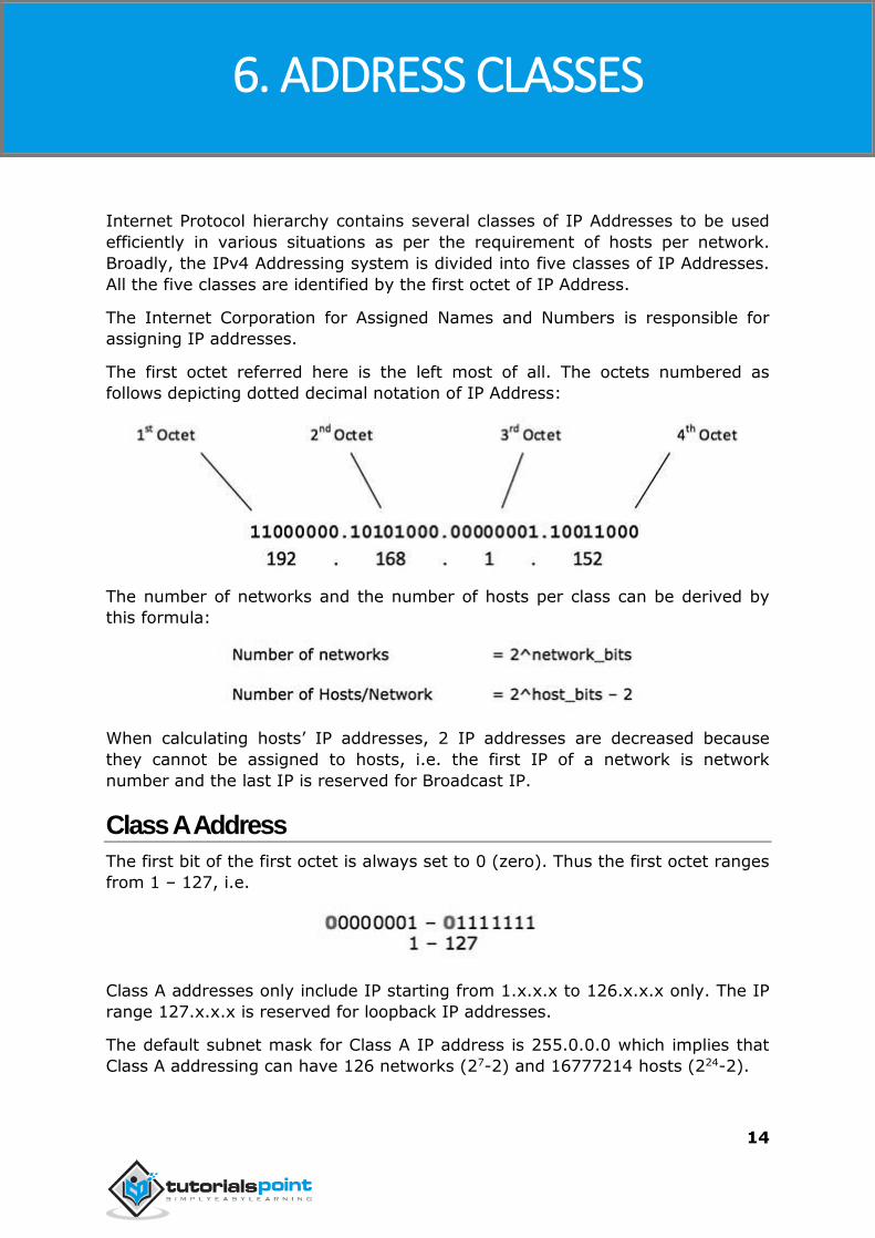
The first octet referred here is the left most of all. The octets numbered as
follows depicting dotted decimal notation of IP Address:
The number of networks and the number of hosts per class can be derived by
this formula:
When calculating hosts’ IP addresses, 2 IP addresses are decreased because
they cannot be assigned to hosts, i.e. the first IP of a network is network
number and the last IP is reserved for Broadcast IP.
Class A Address
The first bit of the first octet is always set to 0 (zero). Thus the first octet ranges
from 1 – 127, i.e.
Class A addresses only include IP starting from 1.x.x.x to 126.x.x.x only. The IP
range 127.x.x.x is reserved for loopback IP addresses.
The default subnet mask for Class A IP address is 255.0.0.0 which implies that
Class A addressing can have 126 networks (27-2) and 16777214 hosts (224-2).
6. ADDRESS CLASSES
Ipv4
15
Class A IP address format is
thus: 0NNNNNNN.HHHHHHHH.HHHHHHHH.HHHHHHHH
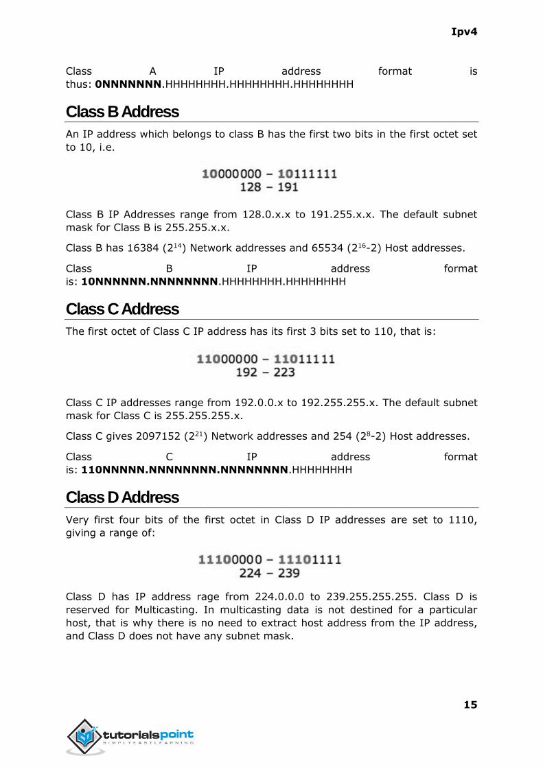
Class B Address
An IP address which belongs to class B has the first two bits in the first octet set
to 10, i.e.
Class B IP Addresses range from 128.0.x.x to 191.255.x.x. The default subnet
mask for Class B is 255.255.x.x.
Class B has 16384 (214) Network addresses and 65534 (216-2) Host addresses.
Class B IP address format
is: 10NNNNNN.NNNNNNNN.HHHHHHHH.HHHHHHHH
Class C Address
The first octet of Class C IP address has its first 3 bits set to 110, that is:
Class C IP addresses range from 192.0.0.x to 192.255.255.x. The default subnet
mask for Class C is 255.255.255.x.
Class C gives 2097152 (221) Network addresses and 254 (28-2) Host addresses.
Class C IP address format
is: 110NNNNN.NNNNNNNN.NNNNNNNN.HHHHHHHH
Class D Address
Very first four bits of the first octet in Class D IP addresses are set to 1110,
giving a range of:
Class D has IP address rage from 224.0.0.0 to 239.255.255.255. Class D is
reserved for Multicasting. In multicasting data is not destined for a particular
host, that is why there is no need to extract host address from the IP address,
and Class D does not have any subnet mask.
Ipv4
16
Class E Address
This IP Class is reserved for experimental purposes only for R&D or Study. IP
addresses in this class ranges from 240.0.0.0 to 255.255.255.254. Like Class D,
this class too is not equipped with any subnet mask.
Ipv4
17
Each IP class is equipped with its own default subnet mask which bounds that IP
class to have prefixed number of Networks and prefixed number of Hosts per
network. Classful IP addressing does not provide any flexibility of having less
number of Hosts per Network or more Networks per IP Class.
CIDR or Classless Inter Domain Routing provides the flexibility of borrowing
bits of Host part of the IP address and using them as Network in Network, called
Subnet. By using subnetting, one single Class A IP address can be used to have
smaller sub-networks which provides better network management capabilities.
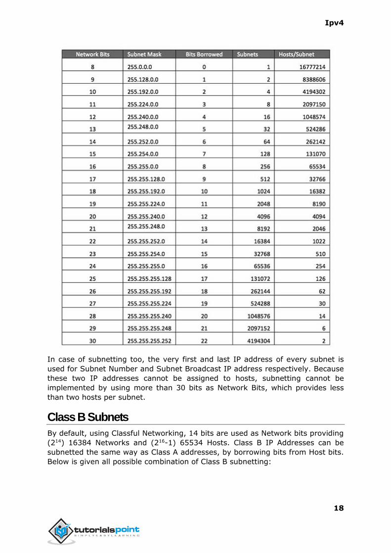
Class A Subnets
In Class A, only the first octet is used as Network identifier and rest of three
octets are used to be assigned to Hosts (i.e. 16777214 Hosts per Network). To
make more subnet in Class A, bits from Host part are borrowed and the subnet
mask is changed accordingly.
For example, if one MSB (Most Significant Bit) is borrowed from host bits of
second octet and added to Network address, it creates two Subnets (21=2) with
(223-2) 8388606 Hosts per Subnet.
The Subnet mask is changed accordingly to reflect subnetting. Given below is a
list of all possible combination of Class A subnets:
7. SUBNETTING
Ipv4
18
In case of subnetting too, the very first and last IP address of every subnet is
used for Subnet Number and Subnet Broadcast IP address respectively. Because
these two IP addresses cannot be assigned to hosts, subnetting cannot be
implemented by using more than 30 bits as Network Bits, which provides less
than two hosts per subnet.
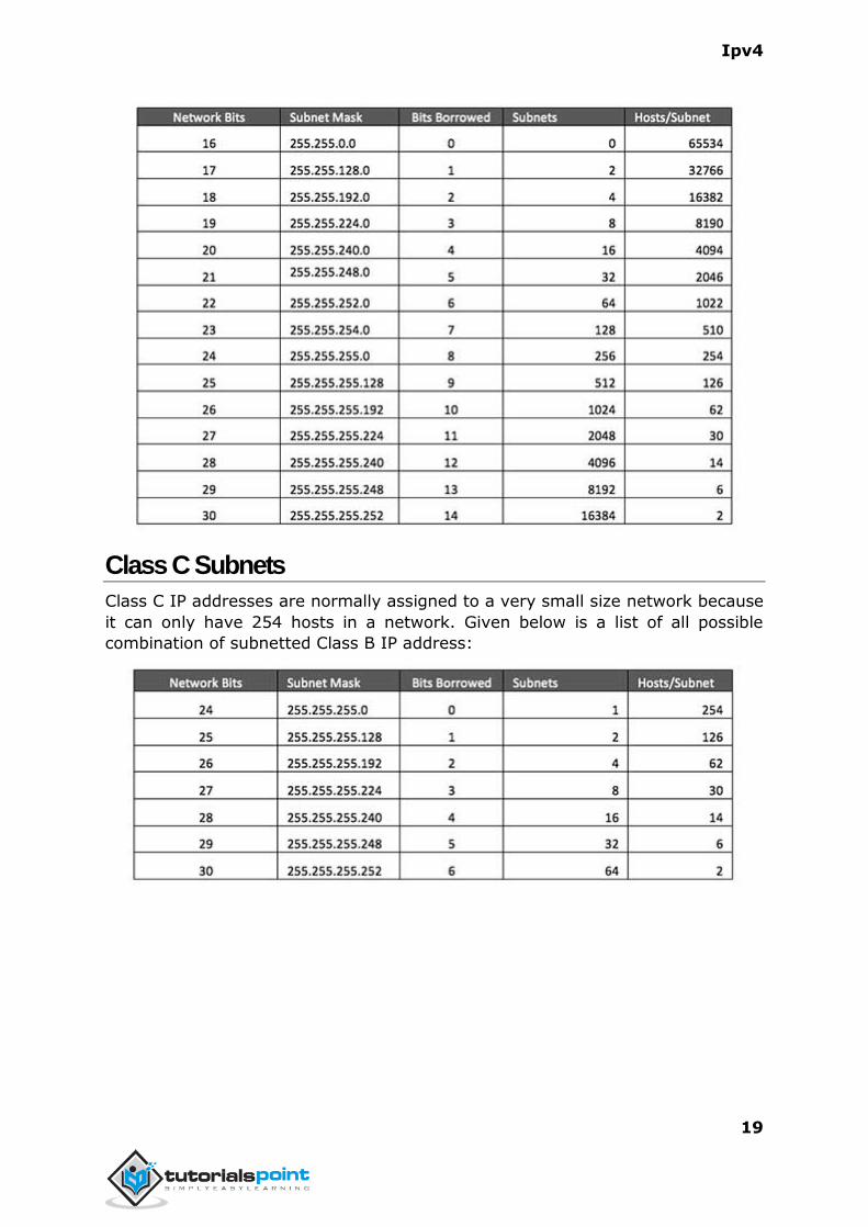
Class B Subnets
By default, using Classful Networking, 14 bits are used as Network bits providing
(214) 16384 Networks and (216-1) 65534 Hosts. Class B IP Addresses can be
subnetted the same way as Class A addresses, by borrowing bits from Host bits.
Below is given all possible combination of Class B subnetting:
Ipv4
19
Class C Subnets
Class C IP addresses are normally assigned to a very small size network because
it can only have 254 hosts in a network. Given below is a list of all possible
combination of subnetted Class B IP address:
Ipv4
20
Internet Service Providers may face a situation where they need to allocate IP
subnets of different sizes as per the requirement of customer. One customer
may ask Class C subnet of 3 IP addresses and another may ask for 10 IPs. For
an ISP, it is not feasible to divide the IP addresses into fixed size subnets, rather
he may want to subnet the subnets in such a way which results in minimum
wastage of IP addresses.
For example, an administrator have 192.168.1.0/24 network. The suffix /24
(pronounced as "slash 24") tells the number of bits used for network address. In
this example, the administrator has three different departments with different
number of hosts. Sales department has 100 computers, Purchase department
has 50 computers, Accounts has 25 computers and Management has 5
computers. In CIDR, the subnets are of fixed size. Using the same methodology
the administrator cannot fulfill all the requirements of the network.
The following procedure shows how VLSM can be used in order to allocate
department-wise IP addresses as mentioned in the example.
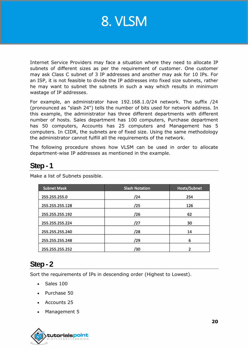
Step - 1
Make a list of Subnets possible.
Step - 2
Sort the requirements of IPs in descending order (Highest to Lowest).
Sales 100
Purchase 50
Accounts 25
Management 5
8. VLSM
Ipv4
21
Step - 3
Allocate the highest range of IPs to the highest requirement, so let's assign
192.168.1.0 /25 (255.255.255.128) to the Sales department. This IP subnet
with Network number 192.168.1.0 has 126 valid Host IP addresses which satisfy
the requirement of the Sales department. The subnet mask used for this subnet
has 10000000 as the last octet.
Step - 4
Allocate the next highest range, so let's assign 192.168.1.128 /26
(255.255.255.192) to the Purchase department. This IP subnet with Network
number 192.168.1.128 has 62 valid Host IP Addresses which can be easily
assigned to all the PCs of the Purchase department. The subnet mask used has
11000000 in the last octet.
Step - 5
Allocate the next highest range, i.e. Accounts. The requirement of 25 IPs can be
fulfilled with 192.168.1.192 /27 (255.255.255.224) IP subnet, which contains 30
valid host IPs. The network number of Accounts department will be
192.168.1.192. The last octet of subnet mask is 11100000.
Step - 6
Allocate the next highest range to Management. The Management department
contains only 5 computers. The subnet 192.168.1.224 /29 with the Mask
255.255.255.248 has exactly 6 valid host IP addresses. So this can be assigned
to Management. The last octet of the subnet mask will contain 11111000.
By using VLSM, the administrator can subnet the IP subnet in such a way that
least number of IP addresses are wasted. Even after assigning IPs to every
department, the administrator, in this example, is still left with plenty of IP
addresses which was not possible if he has used CIDR.
Ipv4
22
There are a few reserved IPv4 address spaces which cannot be used on the
internet. These addresses serve special purpose and cannot be routed outside
the Local Area Network.
Private IP Addresses
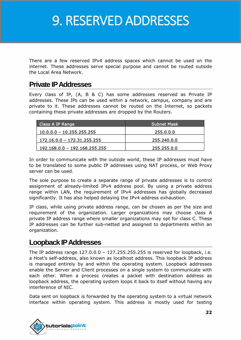
Every class of IP, (A, B & C) has some addresses reserved as Private IP
addresses. These IPs can be used within a network, campus, company and are
private to it. These addresses cannot be routed on the Internet, so packets
containing these private addresses are dropped by the Routers.
In order to communicate with the outside world, these IP addresses must have
to be translated to some public IP addresses using NAT process, or Web Proxy
server can be used.
The sole purpose to create a separate range of private addresses is to control
assignment of already-limited IPv4 address pool. By using a private address
range within LAN, the requirement of IPv4 addresses has globally decreased
significantly. It has also helped delaying the IPv4 address exhaustion.
IP class, while using private address range, can be chosen as per the size and
requirement of the organization. Larger organizations may choose class A
private IP address range where smaller organizations may opt for class C. These
IP addresses can be further sub-netted and assigned to departments within an
organization.
Loopback IP Addresses
The IP address range 127.0.0.0 – 127.255.255.255 is reserved for loopback, i.e.
a Host’s self-address, also known as localhost address. This loopback IP address
is managed entirely by and within the operating system. Loopback addresses
enable the Server and Client processes on a single system to communicate with
each other. When a process creates a packet with destination address as
loopback address, the operating system loops it back to itself without having any
interference of NIC.
Data sent on loopback is forwarded by the operating system to a virtual network
interface within operating system. This address is mostly used for testing
9. RESERVED ADDRESSES
Ipv4
23
purposes like client-server architecture on a single machine. Other than that, if a
host machine can successfully ping 127.0.0.1 or any IP from loopback range,
implies that the TCP/IP software stack on the machine is successfully loaded and
working.
Link-local Addresses
In case a host is not able to acquire an IP address from the DHCP server and it
has not been assigned any IP address manually, the host can assign itself an IP
address from a range of reserved Link-local addresses. Link-local address ranges
from 169.254.0.0 – 169.254.255.255.
Assume a network segment where all systems are configured to acquire IP
addresses from a DHCP server connected to the same network segment. If the
DHCP server is not available, no host on the segment will be able to
communicate to any other. Windows (98 or later), and Mac OS (8.0 or later)
supports this functionality of self-configuration of Link-local IP address. In
absence of DHCP server, every host machine randomly chooses an IP address
from the above mentioned range and then checks to ascertain by means of ARP,
if some other host also has not configured itself with the same IP address. Once
all hosts are using link local addresses of same range, they can communicate
with each other.
These IP addresses cannot help system to communicate when they do not
belong to the same physical or logical segment. These IPs are also not routable.
Ipv4
24
This chapter describes how actual communication happens on the Network using
Internet Protocol version 4.
Packet Flow in Network
All the hosts in IPv4 environment are assigned unique logical IP addresses.
When a host wants to send some data to another host on the network, it needs
the physical (MAC) address of the destination host. To get the MAC address, the
host broadcasts an ARP message and asks to give the MAC address whoever is
the owner of destination IP address. All the hosts on that segment receive the
ARP packet, but only the host having its IP matching with the one in the ARP
message replies with its MAC address. Once the sender receives the MAC
address of the receiving station, data is sent on the physical media.
In case the IP does not belong to the local subnet, the data is sent to the
destination by means of Gateway of the subnet. To understand the packet flow,
we must first understand the following components:
MAC Address: Media Access Control Address is 48-bit factory hard coded
physical address of network device which can uniquely be identified. This
address is assigned by device manufacturers.
Address Resolution Protocol: Address Resolution Protocol is used to
acquire the MAC address of a host whose IP address is known. ARP is a
Broadcast packet which is received by all the host in the network
segment. But only the host whose IP is mentioned in ARP responds to it
providing its MAC address.
Proxy Server: To access the Internet, networks use a Proxy Server which
has a public IP assigned. All the PCs request the Proxy Server for a Server
on the Internet. The Proxy Server on behalf of the PCs sends the request
to the server and when it receives a response from the Server, the Proxy
Server forwards it to the client PC. This is a way to control Internet access
in computer networks and it helps to implement web-based policies.
Dynamic Host Control Protocol: DHCP is a service by which a host is
assigned IP address from a pre-defined address pool. DHCP server also
provides necessary information such as Gateway IP, DNS Server Address,
lease assigned with the IP, etc. By using DHCP services, a network
administrator can manage assignment of IP addresses at ease.
Domain Name System: It is very likely that a user does not know the IP
address of a remote Server he wants to connect to. But he knows the
name assigned to it, for example, tutorialpoints.com. When the user types
the name of a remote server he wants to connect to, the localhost behind
10. EXAMPLE
Ipv4
25
the screens sends a DNS query. Domain Name System is a method to
acquire the IP address of the host whose Domain Name is known.
Network Address Translation: Almost all PCs in a computer network
are assigned private IP addresses which are not routable on the Internet.
As soon as a router receives an IP packet with a private IP address, it
drops it. In order to access servers on public private address, computer
networks use an address translation service, which translates between
public and private addresses, called Network Address Translation. When a
PC sends an IP packet out of a private network, NAT changes the private
IP address with public IP address and vice versa.
We can now describe the packet flow. Assume that a user wants to access
www.TutorialsPoint.com from her personal computer. She has internet
connection from her ISP. The following steps will be taken by the system to help
her reach the destination website.
Step 1 – Acquiring an IP Address (DHCP)
When the user’s PC boots up, it searches for a DHCP server to acquire an IP
address. For the same, the PC sends a DHCPDISCOVER broadcast which is
received by one or more DHCP servers on the subnet and they all respond with
DHCPOFFER which includes all the necessary details such as IP, subnet,
Gateway, DNS, etc. The PC sends DHCPREQUEST packet in order to request the
offered IP address. Finally, the DHCP sends DHCPACK packet to tell the PC that
it can keep the IP for some given amount of time that is known as IP lease.
Alternatively, a PC can be assigned an IP address manually without taking any
help from DHCP server. When a PC is well-configured with IP address details, it
can communicate other computers all over the IP enabled network.
Step 2 – DNS Query
When a user opens a web browser and types www.tutorialpoints.com which is a
domain name and a PC does not understand how to communicate with the
server using domain names, then the PC sends a DNS query out on the network
in order to obtain the IP address pertaining to the domain name. The pre-
configured DNS server responds to the query with IP address of the domain
name specified.
Step 3 – ARP Request
The PC finds that the destination IP address does not belong to his own IP
address range and it has to forward the request to the Gateway. The Gateway in
this scenario can be a router or a Proxy Server. Though the Gateway’s IP
address is known to the client machine but computers do not exchange data on
IP addresses, rather they need the machine’s hardware address which is Layer-2
factory coded MAC address. To obtain the MAC address of the Gateway, the
client PC broadcasts an ARP request saying "Who owns this IP address?" The
Ipv4
26
Gateway in response to the ARP query sends its MAC address. Upon receiving
the MAC address, the PC sends the packets to the Gateway.
An IP packet has both source and destination addresses and it connects the host
with a remote host logically, whereas MAC addresses help systems on a single
network segment to transfer actual data. It is important that source and
destination MAC addresses change as they travel across the Internet (segment
by segment), but source and destination IP addresses never change.
Ipv4
27
The Internet Protocol version 4 was designed to be allocated to approximately
4.3 billion addresses. At the beginning of Internet this was considered a much
wider address space for which there was nothing to worry about.
The sudden growth in internet users and its widespread use has exponentially
increased the number of devices which needs real and unique IPs to be able to
communicate. Gradually, an IP is required by almost every digital equipment
which were made to ease human life, such as Mobile Phones, Cars and other
electronic devices. The number of devices (other than computers/routers)
expanded the demand for extra IP addresses, which were not considered earlier.
Allocation of IPv4 is globally managed by Internet Assigned Numbers Authority
(IANA) under coordination with the Internet Corporation for Assigned Names and
Numbers (ICANN). IANA works closely with Regional Internet Registries, which
in turn are responsible for efficiently distributing IP addresses in their territories.
There are five such RIRs. According to IANA reports, all the IPv4 address blocks
have been allocated. To cope up with the situation, the following practices were
being done:
Private IPs: Few blocks of IPs were declared for private use within a LAN
so that the requirement for public IP addresses can be reduced.
NAT: Network address translation is a mechanism by which multiple
PCs/hosts with private IP addresses are enabled to access using one or
few public IP addresses.
Unused Public IPs were reclaimed by RIRs.
Internet Protocol v6 (IPv6)
IETF (Internet Engineering Task Force) has redesigned IP addresses to mitigate
the drawbacks of IPv4. The new IP address is version 6 which is 128-bit address,
by which every single inch of the earth can be given millions of IP addresses.
Today majority of devices running on Internet are using IPv4 and it is not
possible to shift them to IPv6 in the coming days. There are mechanisms
provided by IPv6, by which IPv4 and IPv6 can co-exist unless the Internet
entirely shifts to IPv6:
Dual IP Stack
Tunneling (6to4 and 4to6)
NAT Protocol Translation
11. SUMMARY