Embed Size (px)
Citation preview
The corporate technical journalreview
ABB
A year of innovations 6 Traction gets a transformation in size 11 Uninterruptable power supply 27 A factory that lives 41
Innovation
1|12

2 ABB review 1|12
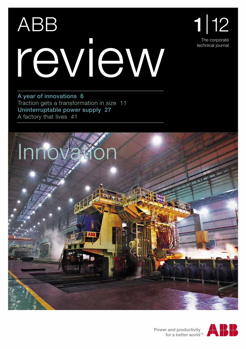
The cover picture of this edition of ABB Review depicts a hot strip mill of the Shagang Group, located in Jiangsu, China. The mill uses both drives and control systems from ABB, contributing to its precision, reliability and efficiency. The installation can roll 3.5 million tons annually.
The inside cover picture shows wind turbines in Hohhot, China. In this remote part of Inner Mongolia, ABB equipment helps harness the power of the wind and transport it to the centers of consumption.
Contents
3Contents
6
11
18
22
27
30
34
41
47
53
56
Innovation highlightsABB’s top innovations for 2012
Traction transformation A power-electronic traction transformer (PETT)
SafeLink CB switchgearAn innovative, integrated secondary distribution solution
SF6 and a world firstABB launches the first-ever SF6 recycling center
Eliminating downtimeKeeping the power flowing during grid instabilities
Power fitnessReliable voltage protection of sensitive loads
The power of integrationReaching new levels of productivity in the automation industry
Controlling the living factoryModeling a mammalian cell culture for an online process control system
The fieldbus outside the fieldSoft FF reduces commissioning effort simulating Foundation Fieldbus
Winning by designInnovative door communication system wins international design award
The frugal manufacturerRegulatory issues set the agenda (part 3)
Innovating usability
Innovating production
Innovating energy
Innovation highlights
ABB review 1|12 4
Editorial
Claes RytoftChief Technology Officer ABB Ltd
Although most of ABB’s products and services are primarily targeted at industries and utilities, ABB does also provide products for the consumer sector, enhancing the comfort of our homes. The new Busch-Welcome® system integrates the functionality of the doorbell, door control and audio and video transmission, coming in an appealing and award-winning design, taking intuitive interaction to a new level. It can use existing doorbell wiring, allowing it to be easily retrofitted to existing buildings.
Further articles look at SafeLink CB switch-gear for secondary distribution, a traction transformer that is lighter and more energy efficient, integration in automation and a case study of the effective application of ABB’s Extended Automation System 800xA in pharmaceuticals.
Continuing with the journal’s look at barriers to energy efficiency in industry, the third and final article in the “Frugal manufacturer” series investigates the effects of regulatory issues on energy efficiency.
Whatever your interests, I trust that this issue of ABB Review will grant you fascinating insights into the company’s innovation process.
Enjoy your reading.
Claes RytoftChief Technology OfficerABB Ltd
Dear Reader,Across the globe, ABB’s more than 7,500 engineers and scientists are working on technologies, products and services for tomorrow. Once a year, ABB Review grants its readers a peek into these labs by dedicating an issue to the theme of innovation.
ABB is a well-established leader in supplying components and systems for the delivery of electrical power, covering virtually everything between (and in some cases including) the generator at one end of the chain and the end user’s power socket at the other. The uncompromised continuity of the power supply is highly critical to many consumers. Besides contributing to this classical supply chain, the company also manufactures the UPS (uninterruptable power supplies) that bridge short interruptions. ABB Review dedicates two articles to the latest develop-ments in UPS technology. ABB’s involvement and capability in this area is broadening with the company’s acquisition of the UPS manufacturer, Newave.
A modern industrial plant has a myriad of sensors, actuators and controllers, whose interaction is vital to the functioning of the process. At the same time, downtime is extremely costly, so on-site testing during commissioning must be reduced to a mini-mum. One way to reduce downtime without sacrificing the thoroughness of the test cycle is to simulate as much as possible in the factory before the equipment is installed on-site. ABB Review presents new break-throughs in simulation for Foundation Fieldbus.
A tribute to innovation

5Editorial
6 ABB review 1|12
Innovation highlights
6 ABB review 1|12
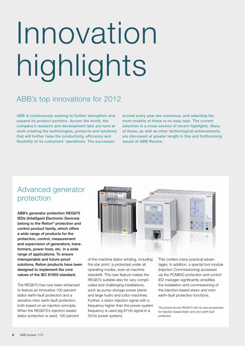
ABB’s generator protection REG670 IEDs (Intelligent Electronic Devices) belong to the Relion® protection and control product family, which offers a wide range of products for the protection, control, measurement and supervision of generators, trans - formers, power lines, etc. in a wide range of applications. To ensure interoperable and future-proof solutions, Relion products have been designed to implement the core values of the IEC 61850 standard.
The REG670 has now been enhanced to feature an innovative 100 percent stator earth-fault protection and a sensitive rotor earth-fault protection, both based on an injection principle. When the REG670’s injection-based stator protection is used, 100 percent
of the machine stator winding, including the star point, is protected under all operating modes, even at machine standstill. This new feature makes the REG670 suitable also for very compli-cated and challenging installations, such as pump-storage power plants and large hydro and turbo machines. Further, a stator injection signal with a frequency higher than the power system frequency is used (eg 87 Hz signal in a 50 Hz power system).
This confers many practical advan-tages. In addition, a special tool module (Injection Commissioning) accessed via the PCM600 protection and control IED manager significantly simplifies the installation and commissioning of the injection-based stator and rotor earth-fault protection functions.
The picture shows REG670 with its new accessories for injection-based stator and rotor earth fault protection.
Advanced generator protection
InnovationhighlightsABB is continuously seeking to further strengthen and expand its product portfolio. Across the world, the company’s research and development labs are hard at work creating the technologies, products and solutions that will further raise the productivity, efficiency and flexibility of its customers’ operations. The successes
scored every year are numerous, and selecting the most notable of these is no easy task. The current selection is a cross section of recent highlights. Many of these, as well as other technological achievements, are discussed at greater length in this and forthcoming issues of ABB Review.
ABB’s top innovations for 2012

7Topic 7Innovation highlights
Photos of visitors can be taken and, during absence, three photos of each visitor are taken automatically after the bell has been rung. The display can be used as a digital picture frame to show favorite photos.
If a building has multiple entrances, then several outdoor video stations may be connected to distribute audio and video throughout the building. This can also be used as an indoor video intercom system.
Its intuitive operation, elegant installa-tion, unobtrusive aesthetics and overall harmony has inspired the design world: the Busch-Welcome was awarded the prestigious “iF product design award 2012” and has now also been awarded the label “Interior Innovation Award – Winner 2012” for four of its products.
The Busch-Jaeger door communication system represents the very newest technology in door entry systems. But its aesthetics have also attracted attention: the product won the presti-gious “Interior Innovation Award – Winner 2012” in the run-up to the imm cologne 2012 trade fair.
The Busch-Welcome® range of products allows tenants to communicate with visitors at the front door. The product range goes from audio-only all the way up to an outdoor, high-resolution color camera delivering images to the indoor 17.8 cm (7”) TFT touch-panel display.
Busch-Jaeger opens the door to design award
Few would disagree that an indi-vidual who takes responsibility for his own energy consumption consequently improves his usage behavior. And even small improve-ments, when accumulated over many such individuals, can have a significant, positive impact on resource conservation and green-house gas reduction. Yet how many can state with any degree of accu-racy how much water, gas, oil or electricity they used yesterday? Very few, and that is because the relevant data is difficult for the individual to get at and meaningfully collate.
A new range of products from Busch-Jaeger now changes all that. The Busch-EnergyControl®, Busch-EnergyDisplay® and Busch-Comfort-Panel®, in combination with the energy-data gateway, ensure optimum energy transparency.
Controlling consumption
Busch-Jaeger is a member of the ABB Group.For more information about the Busch-Jaeger door communication system please refer to “Winning by design” on page 53 of this issue of ABB Review.
These products allow the consumer to closely monitor and control energy usage, and exploit off-peak energy. They are not only seamlessly integrat-ed with the building system technol-ogy, but they can also provide Internet access, entertainment facilities and IP-based communication. Thus, from one display, the user can consult and control his energy usage as well as call up Internet pages, receive and send emails, exploit VoIP, play MP3s or watch video clips.
Internal communication with other Busch-ComfortPanels is possible via video telephone using the integrated video camera. The camera facilitates room monitoring and can even be used as a baby monitor.
These products will be presented more fully in issue 2/2012 of ABB Review.

8 ABB review 1|12 8 ABB review 1|12
Next time you see a thunderstorm discharge thousands of amps at several million volts, spare a thought for the sensitive manufacturing processes which have to withstand these mighty onslaughts from Mother Nature. ABB is a major supplier of technology which enables them to do so, and the PCS100 Active Voltage Conditioner (AVC) and the PCS100 Uninterruptable Power Supply (UPS-I) are just two of the latest examples of such technology.
Sensitive manufacturing processes require a rock-steady and continuous power supply. But natural phenomena and events on the power grid conspire to make life difficult and, potentially, very
One business segment enjoying growth is the data center industry. In other words, the collections of servers and storage devices that support websites like Face-book (incidentally, ABB has been chosen to power Facebook’s first data center outside the United States) and Google, as well as banking systems, health records and a myriad of other applications. Recently, though, data centers have come under scrutiny for their conspicuous energy con-sumption.
Before power from the AC grid finds its way down to individual micro-processors or disc drives in a data center, it will have undergone multiple AC-DC-AC conversions, during which some 50 percent of the energy can be lost.
expensive. However, the PCS100 Active Voltage Conditioner (AVC) can protect plant against voltage sags of 30 percent and voltage dropouts of 30 seconds duration.
Should the power drop out completely, the offline UPS system PCS100 UPS-I (Industrial) will save the day. When trouble arises, it will immediately disconnect the load from the main supply and then maintain power until diesel back-up generators can be started. It is equipped with high-perfor-mance, low-maintenance capacitors or state-of-the-art battery technology and offers effective protection against short-term interruptions or power outages of up to 30s duration.
For more information about the ABB AVC and UPS-I products, please refer to “Power fitness” on page 30 of this issue of ABB Review.
An attractive alternative is DC power. Using a DC approach makes for a simpler overall architecture that is less costly to install and takes up less space. DC requires fewer voltage transformations, it produces less heat and requires less cooling. It also facilitates the exploitation of the native DC produced by wind and solar sources.
There are already a number of data centers running on DC power sys-tems. A confluence of trends points to a broader proliferation in future. It is likely that as these trends continue and the data center industry evolves, more DC-powered data centers will appear on the landscape.
These developments will be discussed more fully in an upcoming edition of ABB Review.
Caution: Sensitive load
Taking the direct route
9Topic 9Innovation highlights
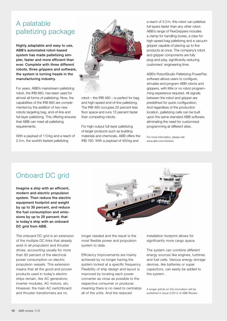
the case of the demonstrator) to a higher frequency, which permits the transformer to be of much smaller and lighter construction. The future generation of PETT that is currently under develop-ment is set to achieve a power density of 0.5 to 0.75 kVA/kg (compared with 0.2 to 0.35 kVA/kg for a conventional transformer + inverter combination). At the same time, energy efficiency is being increased from the previous range of 88 to 90 percent to more than 95 percent.
For more information on the PETT, please see “Traction transformation” on pages 11 to 17 of this edition of ABB Review.
The traction transformer is one of the heaviest single pieces of equipment on a train. ABB is making this massive component of iron and copper lighter by introducing power electronics to raise the frequency. In 2011 ABB built a PETT demonstrator and fitted it to a locomotive. Testing of this locomotive began in early 2012.
The PETT replaces the transformer and inverter combination by a lighter and more energy-efficient alternative. It converts the line frequency (16.7 Hz in
From iron to silicon – the power-electronic traction transformer (PETT)
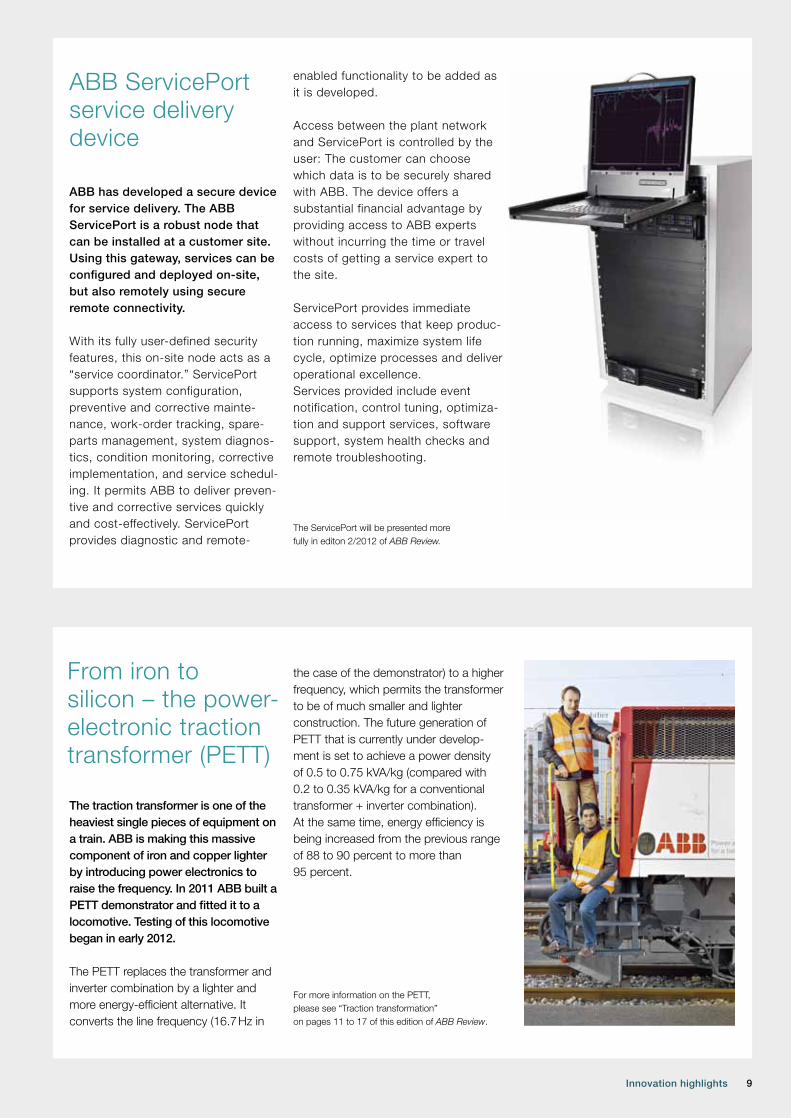
ABB has developed a secure device for service delivery. The ABB ServicePort is a robust node that can be installed at a customer site. Using this gateway, services can be configured and deployed on-site, but also remotely using secure remote connectivity.
With its fully user-defined security features, this on-site node acts as a “service coordinator.” ServicePort supports system configuration, preventive and corrective mainte-nance, work-order tracking, spare-parts management, system diagnos-tics, condition monitoring, corrective implementation, and service schedul-ing. It permits ABB to deliver preven-tive and corrective services quickly and cost-effectively. ServicePort provides diagnostic and remote-
enabled functionality to be added as it is developed.
Access between the plant network and ServicePort is controlled by the user: The customer can choose which data is to be securely shared with ABB. The device offers a substantial financial advantage by providing access to ABB experts without incurring the time or travel costs of getting a service expert to the site.
ServicePort provides immediate access to services that keep produc-tion running, maximize system life cycle, optimize processes and deliver operational excellence. Services provided include event notification, control tuning, optimiza-tion and support services, software support, system health checks and remote troubleshooting.
The ServicePort will be presented more fully in editon 2/2012 of ABB Review.
ABB ServicePort service delivery device
10 ABB review 1|12 10 ABB review 1|12
Highly adaptable and easy to use, ABB’s automated robot-based system has made palletizing sim- pler, faster and more efficient than ever. Complete with three different robots, three grippers and software, the system is turning heads in the manufacturing industry.
For years, ABB’s mainstream palletizing robot, the IRB 660, has been used for almost all forms of palletizing. Now, the capabilities of the IRB 660 are comple-mented by the addition of two new robots targeting bag, end-of-line and full-layer palletizing. This offering ensures that ABB can meet all palletizing requirements.
With a payload of 110 kg and a reach of 2.4 m, the world’s fastest palletizing
robot – the IRB 460 – is perfect for bag and high-speed end-of-line palletizing. The IRB 460 occupies 20 percent less floor space and runs 15 percent faster than competing robots.
For high-output full-layer palletizing of larger products such as building materials and chemicals, ABB offers the IRB 760. With a payload of 450 kg and
a reach of 3.2 m, this robot can palletize full layers faster than any other robot. ABB’s range of FlexGrippers includes a clamp for handling boxes, a claw for high-speed bag palletizing and a vacuum gripper capable of placing up to five products at once. The company’s robot and gripper components are fully plug-and-play, significantly reducing customers’ engineering time.
ABB’s RobotStudio Palletizing PowerPac software allows users to configure, simulate and program ABB robots and grippers, with little or no robot program-ming experience required. All signals between the robot and gripper are predefined for quick configuration. And regardless of the production location, palletizing cells can be built upon the same standard ABB software, eliminating the need for customized programming at different sites.
For more information, please visit www.abb.com/robotics
A palatable palletizing package
Imagine a ship with an efficient, modern and electric propulsion system. Then reduce the electric equipment footprint and weight by up to 30 percent, and reduce the fuel consumption and emis- sions by up to 20 percent: that is today’s ship with an onboard DC grid from ABB.
The onboard DC grid is an extension of the multiple DC links that already exist in all propulsion and thruster drives, accounting usually for more than 80 percent of the electrical power consumption on electric propulsion vessels. This extension means that all the good and proven products used in today’s electric ships remain, like AC generators, inverter modules, AC motors, etc. However, the main AC switchboard and thruster transformers are no
Onboard DC grid
installation footprint allows for significantly more cargo space. The system can combine different energy sources like engines, turbines and fuel cells. Various energy storage devices, like batteries or super capacitors, can easily be added to the system.
A longer article on this innovation will be published in issue 2/2012 of ABB Review.
longer needed and the result is the most flexible power and propulsion system to date.
Efficiency improvements are mainly achieved by no longer having the system locked at a specific frequency. Flexibility of ship design and layout is improved by locating each power converter as close as possible to the respective consumer or producer, meaning there is no need to centralize all of the units. And the reduced
11Traction transformation 11
Traction transformationA power-electronic traction transformer (PETT)
MAx CLAESSENS, DRAzEN DUJIC, FRANCISCO CANALES, JUER -
GEN K. STEINKE, PHILIPPE STEFANUTTI, CHRISTIAN VETTERLI –
It is often said that small is beautiful. But when it comes to technology, there are numerous other reasons that smaller is better. In many applications weight and space requirements directly influence productivity, and much research effort goes into footprint reduction. Some products, however, have largely resisted this tendency. The minimum size of a power transformer is essentially determined by the laws of physics, as the core must have certain dimensions to accommodate the magnetic field. One especially challenging application area for transformers is traction. The more space the trans-
former occupies, the less is available for passengers on the train. Its weight is also a factor in terms of permissible train axle load and additional energy needed to accelerate it. In terms of making this component smaller and lighter, the laws of physics fortunately provide some scope for improvement in the form of frequency. The higher this is, the smaller the required core. This principle is also found in low-power devices such as laptop chargers. But applying it to such large and heavy-duty items as traction transformers is not just about scaling. ABB has taken on the challenge and devel-oped a prototype power-electronic transformer that is currently being tested in a real locomotive.
12 ABB review 1|12
For historical reasons, railways today use a multitude of different electrification sys-tems, often based on what was state-of-the-art when electrification first began in a particular country or area ➔ 1.
On traditional trains pulled by loco-motives, the heavy transformer is not necessarily a disadvantage as it con-tributes to adhesion: The maximum force that the locomotive can apply to pull a train without losing adhesion on the rails is limited by the weight of the locomotive. In modern passenger trains, however, there is a tendency
toward multiple-unit trains where the traction equip-ment is not con-centrated in the locomotive but distributed along the length of the train in the same vehicles in which passengers travel. With the increased number of pow-
ered axles, adhesion is no longer a lim-iting factor for the train’s acceleration, but the weight and size of the trans-former remain a major constraint for train designers.
An ideal train would thus combine the low weight and small equipment footprint of DC trains with the low transmission losses of high-voltage AC electrification. Essentially, the chal-lenge lies in making the transformer lighter.
In the early days of electric railways, DC was the most common power supply. As it was at the time not feasible to step down DC voltages
onboard the train, transmission between the substation and the train had to be at a low voltage (between 750 V and 3,000 V) so that it could be fed directly to the
traction motors. The disadvantage of the low voltage was that it caused high con-duction losses in the overhead line.
Later, single-phase AC electrification using higher voltages was introduced (15 kV / 16.7 Hz and 25 kV / 50 Hz), reduc-ing transmission losses. The penalty, how-ever, was the large and heavy transform-ers that had to be carried on the train.
Unfortunately, the basic size and weight of a transformer are limited by the laws of physics. Factors determining the minimum size of a transformer include the frequency and the power rating – lower frequencies require larger trans-formers. A higher frequency transform-er would permit weight savings as well as space savings. This is the motivation behind ABB’s power-electronic traction transformer (PETT).
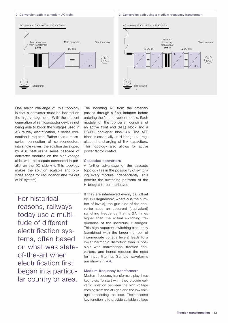
Principle of the PETTThe power conversion path found in most modern AC trains is shown in ➔ 2.
Current from the AC catenary (overhead line) flows through the primary windings of a low-frequency transformer (LFT) to the rail (which provides the return path). The reduced voltage available at the secondary windings of the transformer is fed into a four-quadrant line chopper converting it to DC-link voltage. An in-verter converts this to variable-frequen-cy and variable-voltage AC for the trac-tion motors. Auxiliary supplies can also be fed from the DC link.
To use a medium-frequency transformer (MFT), a frequency converter must be placed before the transformer as shown in ➔ 3. On the secondary side of the transformer, a rectifier converts this to the DC link voltage.
As most other types of large transformers tend to be stationary, traction is probably the application that stands to benefit most from reducing the transformer’s weight.
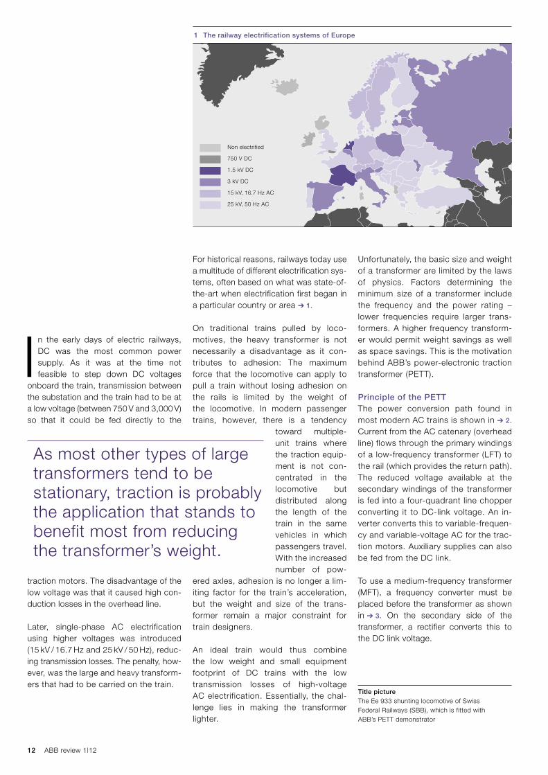
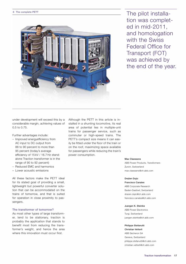
Title pictureThe Ee 933 shunting locomotive of Swiss Federal Railways (SBB), which is fitted with ABB’s PETT demonstrator
Non electrified
750 V DC
1.5 kV DC
3 kV DC
15 kV, 16.7 Hz AC
25 kV, 50 Hz AC
1 The railway electrification systems of Europe
13Traction transformation
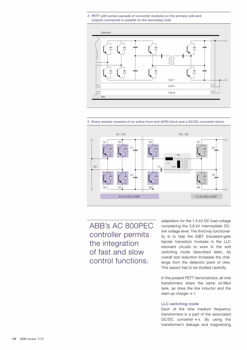
The incoming AC from the catenary passes through a filter inductor before entering the first converter module. Each module of the converter consists of an active front end (AFE) block and a DC/DC converter block ➔ 5. The AFE block is essentially an H-bridge that reg-ulates the charging of link capacitors. This topology also allows for active power factor control.
Cascaded convertersA further advantage of the cascade topology lies in the possibility of switch-ing every module independently. This permits the switching patterns of the H-bridges to be interleaved.
If they are interleaved evenly (ie, offset by 360 degnees/N, where N is the num-ber of levels), the grid side of the con-verter sees an apparent (equivalent) switching frequency that is 2 N times higher than the actual switching fre-quencies of the individual H-bridges. This high apparent switching frequency (combined with the larger number of inter mediate voltage levels) leads to a lower harmonic distortion than is pos-sible with conventional traction con-verters, and hence reduces the need for input filtering. Sample waveforms are shown in ➔ 6.
Medium-frequency transformers Medium-frequency transformers play three key roles. To start with, they provide gal-vanic isolation between the high voltage coming from the AC grid and the low volt-age connecting the load. Their second key function is to provide suitable voltage
One major challenge of this topology is that a converter must be located on the high-voltage side. With the present generation of semiconductor devices not being able to block the voltages used in AC railway electrification, a series con-nection is required. Rather than a mass-series connection of semiconductors into single valves, the solution developed by ABB features a series cascade of converter modules on the high-voltage side, with the outputs connected in par-allel on the DC side ➔ 4. This topology makes the solution scalable and pro-vides scope for redundancy (the “M out of N” system).
For historical reasons, railways today use a multi-tude of different electrification sys-tems, often based on what was state-of-the-art when electrification first began in a particu-lar country or area.
AC catenary 15 KV, 16.7 Hz / 25 KV, 50 Hz
Rail (ground)
Low-frequencymain transformer
(LFT)
1
Main converter
DC link
Traction motor
M
2 Conversion path in a modern AC train
3
3
3 Conversion path using a medium-frequency transformer
AC catenary 15 KV, 16.7 Hz / 25 KV, 50 Hz
Rail (ground)
Medium-frequency
transformer(MFT)
1
HV DC link LV DC link
Traction motor
M3
3
14 ABB review 1|12
adaptation for the 1.5 kV DC load voltage considering the 3.6 kV intermediate DC-link voltage level. The third key functional-ity is to help the IGBT (insulated-gate bipolar transistor) modules in the LLC resonant circuits to work in the soft switching mode (described later). As overall size reduction increases the chal-lenge from the dielectric point of view. This aspect has to be studied carefully.
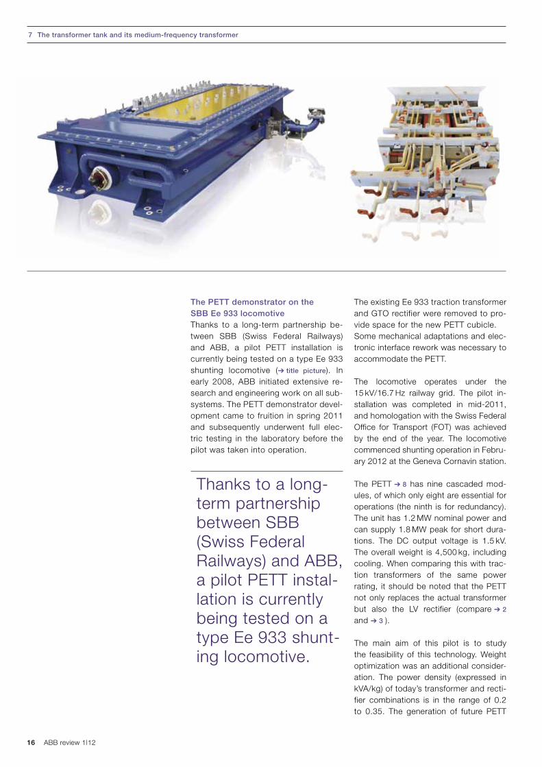
In the present PETT demonstrator, all nine transformers share the same oil-filled tank, as does the line inductor and the start-up charger ➔ 7.
LLC switching modeEach of the nine medium frequency transformers is a part of the associated DC/DC converter ➔ 4. By using the trans former’s leakage and magnetizing
ABB’s AC 800PEC controller permits the integration of fast and slow control functions.
4 PETT with series cascade of converter modules on the primary side and outputs connected in parallel on the secondary side
Rail
Catenary
Cell 2
Cell 1
Cell N
5 Every module consists of an active front end (AFE) block and a DC/DC converter block.
AC / DC
6.5 kV 400 A IGBT
S1 S5 S7
Cr Lm
TR
Lr
SC
S2 S6 S8
S3
S4
C2 C4
C1 C3
DC / DC
3.3 kV 800 A IGBT
15Traction transformation
inductances and the external circuit’s capacitors, a resonant LLC circuit is cre-ated (Lr, Lm and Cr as shown in ➔ 5). The advantages of an LLC circuit include:– Wide output-regulation range– Reduction of switching losses on the
primary side through zero voltage switching (ZVS) over the entire load range
– Low turnoff current controlled by the design (not truly zero current switch-ing, ZCS)
– Low-voltage stress and ZCS on the secondary side diode rectifier
– Load-independent operation at resonant frequency
As an LLC circuit is based on the princi-ple of resonance, variation of the switch-ing frequency can be used to control the output voltage. However, in the present
PETT implementation, this feature has not been used and the LLC resonant DC/DC converter operates in the open loop with a fixed switching frequency of 1.75 kHz, which is below the resonant frequency.
The control systemThe control targets can be summarized as:– Maintaining sinusoidal input current– Near-unity power factor– Constant average DC-link voltage– Grid harmonic rejection
The hardware is ABB’s AC 800PEC con-troller, a platform that permits the inte-gration of fast and slow control functions.
The PETT’s com-pact size means it can easily be fitted under the floor of the train or on the roof, maximizing space available for passengers while reducing the train’s power consump-tion.
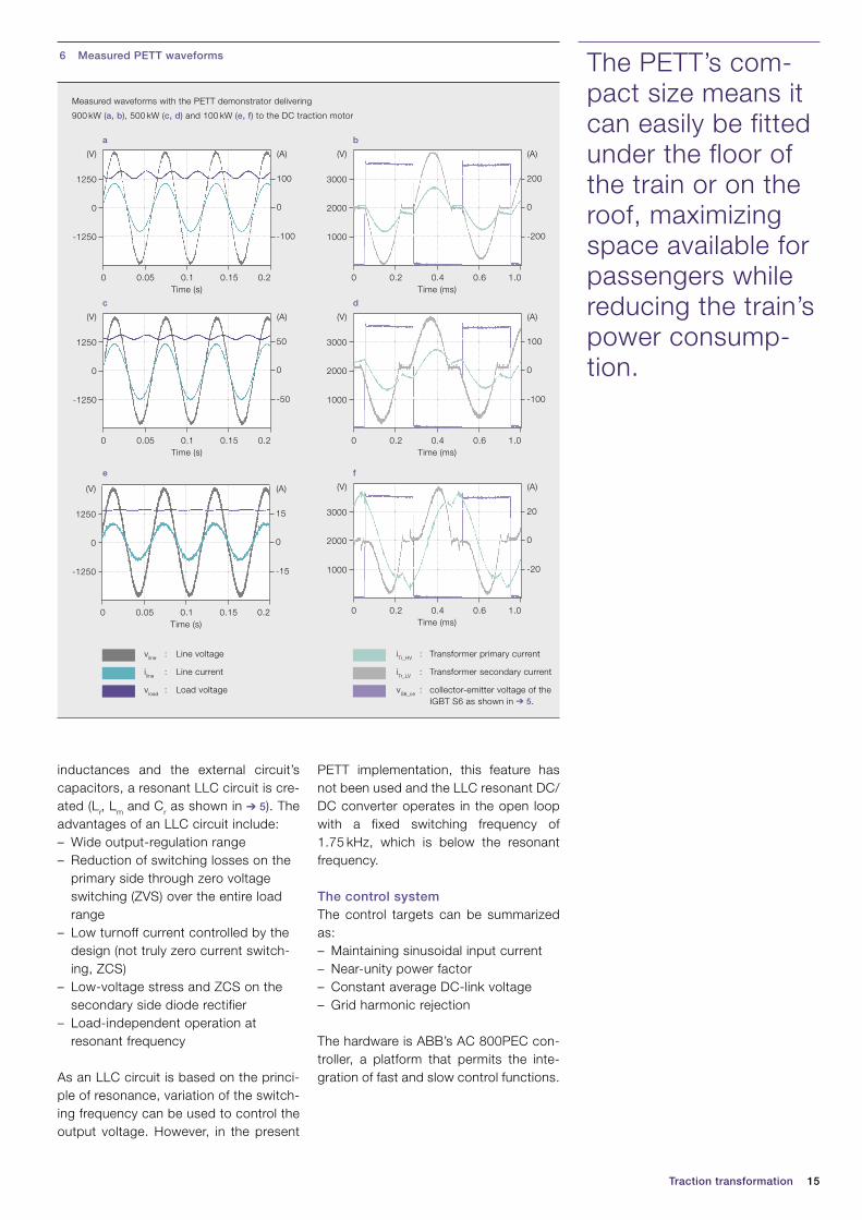
6 Measured PETT waveforms
Measured waveforms with the PETT demonstrator delivering
900 kW (a, b), 500 kW (c, d) and 100 kW (e, f) to the DC traction motor
iTr_HV : Transformer primary current
iTr_LV : Transformer secondary current
vS6_ce : collector-emitter voltage of the IGBT S6 as shown in ➔ 5.
vline : Line voltage
iline : Line current
vload : Load voltage
-1250
0
1250
(V)
-50
0
50
(A)
0.050 0.15 0.20.1Time (s)
1000
2000
3000
(V)
-200
0
200
(A)
0.20 0.6 1.00.4Time (ms)
1000
2000
3000
(V)
-100
0
100
(A)
0.20 0.6 1.00.4Time (ms)
1000
2000
3000
(V)
-20
0
20
(A)
0.20 0.6 1.00.4Time (ms)
-1250
0
1250
(V)
-15
0
15
(A)
0.050 0.15 0.20.1Time (s)
-1250
0
1250
(V)
-100
0
100
(A)
0.050 0.15 0.20.1Time (s)
a
c
e
b
d
f
16 ABB review 1|12
The PETT demonstrator on the SBB Ee 933 locomotiveThanks to a long-term partnership be-tween SBB (Swiss Federal Railways) and ABB, a pilot PETT installation is currently being tested on a type Ee 933 shunting locomotive (➔ title picture). In early 2008, ABB initiated extensive re-search and engineering work on all sub-systems. The PETT demonstrator devel-opment came to fruition in spring 2011 and subsequently underwent full elec-tric testing in the laboratory before the pilot was taken into operation.
The existing Ee 933 traction transformer and GTO rectifier were removed to pro-vide space for the new PETT cubicle.Some mechanical adaptations and elec-tronic interface rework was necessary to accommodate the PETT.
The locomotive operates under the 15 kV/16.7 Hz railway grid. The pilot in-stallation was completed in mid-2011, and homologation with the Swiss Federal Office for Transport (FOT) was achieved by the end of the year. The locomotive commenced shunting operation in Febru-ary 2012 at the Geneva Cornavin station.
The PETT ➔ 8 has nine cascaded mod-ules, of which only eight are essential for operations (the ninth is for redundancy). The unit has 1.2 MW nominal power and can supply 1.8 MW peak for short dura-tions. The DC output voltage is 1.5 kV. The overall weight is 4,500 kg, including cooling. When comparing this with trac-tion transformers of the same power rating, it should be noted that the PETT not only replaces the actual transformer but also the LV rectifier (compare ➔ 2 and ➔ 3 ).
The main aim of this pilot is to study the feasibility of this technology. Weight optimization was an additional consider-ation. The power density (expressed in kVA/kg) of today’s transformer and recti-fier combinations is in the range of 0.2 to 0.35. The generation of future PETT
7 The transformer tank and its medium-frequency transformer
Thanks to a long-term partnership between SBB (Swiss Federal Railways) and ABB, a pilot PETT instal-lation is currently being tested on a type Ee 933 shunt-ing locomotive.
17Traction transformation
under development will exceed this by a considerable margin, achieving values of 0.5 to 0.75.
Further advantages include:– Improved energyefficiency from
AC input to DC output from 88 to 90 percent to more than 95 percent (today’s average efficiency of 15 kV / 16.7 Hz stand-alone Traction transformer is in the range of 90 to 92 percent)
– Reduced EMC and harmonics– Lower acoustic emissions
All these factors make the PETT ideal for its stated goal of providing a small, lightweight but powerful converter solu-tion that can be accommodated on the trains of tomorrow, and that is suited for operation in close proximity to pas-sengers.
The transformer of tomorrow?As most other types of large transform-er, tend to be stationary, traction is probably the application that stands to benefit most from reducing the trans-former’s weight, and hence the area where this innovation must occur first.
Although the PETT in this article is in-stalled in a shunting locomotive, its real area of potential lies in multiple-unit trains for passenger service, such as commuter or high-speed trains. The PETT’s compact size means it can eas-ily be fitted under the floor of the train or on the roof, maximizing space available for passengers while reducing the train’s power consumption.
Max Claessens
ABB Power Products, Transformers
Zurich, Switzerland
Dražen Dujic
Francisco Canales
ABB Corporate Research
Baden-Daettwil, Switzerland
Juergen K. Steinke
ABB Power Electronics
Turgi, Switzerland
Philippe Stefanutti
Christian Vetterli
ABB Sécheron SA
Geneva, Switzerland
8 The complete PETT The pilot installa-tion was complet-ed in mid-2011, and homologation with the Swiss Federal Office for Transport (FOT) was achieved by the end of the year.

18 ABB review 1|12
PRAVIN FUTANE, GERHARD SALGE, SUBBIAH THEVAR DUKKAIAPPAN,
V. RAMESH – Modern medium-voltage secondary distribution networks demand that functions such as grounding, switching, disconnecting, cable connections, busbar extension and protec-tion are integrated within compact, cost-effective and mainte-nance-free functional units. SafeLink CB, ABB’s new outdoor ring main unit, which was developed for the 12 kV low-end secondary distribution network, does exactly that. The latest addition to ABB’s “Safe” series of medium-voltage products, SafeLink CB offers a low-cost, safe, compact, robust and maintenance-free solution for distribution applications.
An innovative, integrated secondary distribution solution
SafeLink CB switchgear
19SafeLink CB switchgear
As standardization is important in engi-neering quality products, proven EL spring actuators are used for the vacuum circuit breaker (VCB) module. EL2 actua-tors have multiple built-in features and are rugged, durable and capable of a high number of mechanical operations.
ABB’s cable bushings for SF6 switchgear also have demonstrated their high per-formance across a large installed base in distribution networks, power stations and industrial complexes. In locations with humidity or condensation problems, for example, the use of cable bushings together with fully screened connectors is particularly valuable.
The environmentally friendly manufactur-ing processes involved in the production of the SafeLink CB RMU switchgear con-form with ISO 9001 and ISO 14001. The materials are carefully selected to ensure maximum reuse at the end of life and have a recycling capability of around 95 percent.
Module design and ratingThe SafeLink CB RMU switchgear cov-ers the most common nominal voltage rating of 12 kV, maximum current of 630 A and short-circuit current of 21 kA. It is suitable for both indoor and outdoor conditions. Currently it is available as
A BB’s SafeLink CB secondary SF6 gas-insulated ring main unit (RMU) switchgear was designed and developed at
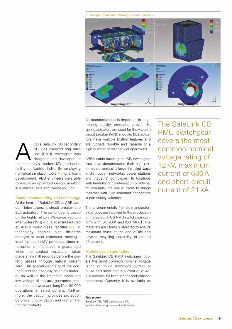
the company’s modern MV production facility in Nashik, India. By employing numerical simulation tools ➔ 1 for efficient development, ABB engineers were able to ensure an optimized design, resulting in a reliable, safe and robust solution.
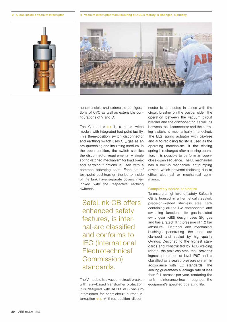
Sound manufacturing and technologyAt the heart of SafeLink CB lie ABB vac-uum interrupters, a circuit breaker and EL2 actuators. The switchgear is based on the highly reliable VG-series vacuum interrupters (VIs) ➔ 2, also manufactured at ABB’s world-class facilities ➔ 3. VI technology enables high dielectric strength at short distances, making it ideal for use in MV products, since in-terruption of the circuit is guaranteed when the contact separation takes place a few milliseconds before the cur-rent passes through natural current zero. The special geometry of the con-tacts and the specially selected materi-al, as well as the limited duration and low voltage of the arc, guarantee mini-mum contact wear and long life – 30,000 operations at rated current. Further-more, the vacuum provides protection by preventing oxidation and contamina-tion of contacts.
1 Design optimization through simulation tools
The SafeLink CB RMU switchgear covers the most common nominal voltage rating of 12 kV, maximum current of 630 A and short-circuit current of 21 kA.
Title picture SafeLink CB, ABB’s secondary SF6 gas-insulated ring main unit switchgear
20 ABB review 1|12
nonextensible and extensible configura-tions of CVC as well as extensible con-figurations of V and C.
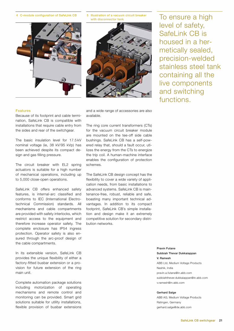
The C module ➔ 4 is a cable-switch module with integrated test point facility. This three-position switch disconnector and earthing switch uses SF6 gas as an arc-quenching and insulating medium. In the open position, the switch satisfies the disconnector requirements. A single spring-latched mechanism for load break and earthing functions is used with a common operating shaft. Each set of test-point bushings on the bottom side of the tank have separate covers inter-locked with the respective earthing switches.
The V module is a vacuum circuit breaker with relay-based transformer protection. It is designed with ABB’s VG5 vacuum interrupters for short-circuit current in-terruption ➔ 5. A three-position discon-
nector is connected in series with the circuit breaker on the busbar side. The operation between the vacuum circuit breaker and the disconnector, as well as between the disconnector and the earth-ing switch, is mechanically interlocked. The EL2 spring actuator with trip-free and auto-reclosing facility is used as the operating mechanism. If the closing spring is recharged after a closing opera-tion, it is possible to perform an open-close-open sequence. The EL mechanism has a built-in mechanical antipumping device, which prevents reclosing due to either electrical or mechanical com-mands.
Completely sealed enclosureTo ensure a high level of safety, SafeLink CB is housed in a hermetically sealed, precision-welded stainless steel tank containing all the live components and switching functions. Its gas-insulated switchgear (GIS) design uses SF6 gas and has a rated filling pressure of 1.2 bar (absolute). Electrical and mechanical bush ings penetrating the tank are clamped and sealed by high-quality O-rings. Designed to the highest stan-dards and constructed by ABB welding robots, the stainless steel tank provides ingress protection of level IP67 and is classified as a sealed pressure system in accordance with IEC standards. The sealing guarantees a leakage rate of less than 0.1 percent per year, rendering the tank maintenance-free throughout the equipment’s specified operating life.
3 Vacuum interrupter manufacturing at ABB’s factory in Ratingen, Germany2 A look inside a vacuum interrupter
SafeLink CB offers enhanced safety features, is inter-nal-arc classified and conforms to IEC (International Electrotechnical Commission) standards.
21SafeLink CB switchgear
FeaturesBecause of its footprint and cable termi-nation, SafeLink CB is compatible with installations that require cable entry from the sides and rear of the switchgear.
The basic insulation level for 17.5 kV nominal voltage (ie, 38 kV/95 kVp) has been achieved despite its compact de-sign and gas filling pressure.
The circuit breaker with EL2 spring actuators is suitable for a high number of mechanical operations, including up to 5,000 close-open operations.
SafeLink CB offers enhanced safety features, is internal-arc classified and conforms to IEC (International Electro-technical Commission) standards. All mechanisms and cable compartments are provided with safety interlocks, which restrict access to the equipment and therefore increase operator safety. The complete enclosure has IP54 ingress protection. Operator safety is also en-sured through the arc-proof design of the cable compartments.
In its extensible version, SafeLink CB provides the unique flexibility of either a factory-fitted busbar extension or a pro-vision for future extension of the ring main unit.
Complete automation package solutions including motorization of operating mechanisms and remote control and monitoring can be provided. Smart grid solutions suitable for utility installations, flexible provision of busbar extensions
and a wide range of accessories are also available.
The ring core current transformers (CTs) for the vacuum circuit breaker module are mounted on the tee-off side cable bushings. SafeLink CB has a self-pow-ered relay that, should a fault occur, uti-lizes the energy from the CTs to energize the trip coil. A human-machine interface enables the configuration of protection schemes.
The SafeLink CB design concept has the flexibility to cover a wide variety of appli-cation needs, from basic installations to advanced systems. SafeLink CB is main-tenance-free, robust, reliable and safe, boasting many important technical ad-vantages. In addition to its compact footprint, SafeLink CB’s simple installa-tion and design make it an extremely competitive solution for secondary distri-bution networks.
Pravin Futane
Subbiah Thevar Dukkaiappan
V. Ramesh
ABB Ltd, Medium Voltage Products
Nashik, India
Gerhard Salge
ABB AG, Medium Voltage Products
Ratingen, Germany
4 C-module configuration of SafeLink CB 5 Illustration of a vacuum circuit breaker with disconnector tank To ensure a high
level of safety, SafeLink CB is housed in a her-metically sealed, precision-welded stainless steel tank containing all the live components and switching functions.
22 ABB review 1|12
BRETT ALExANDER, DUNCAN ROBBIE, MARCUS MARENGHI, MICHELLE
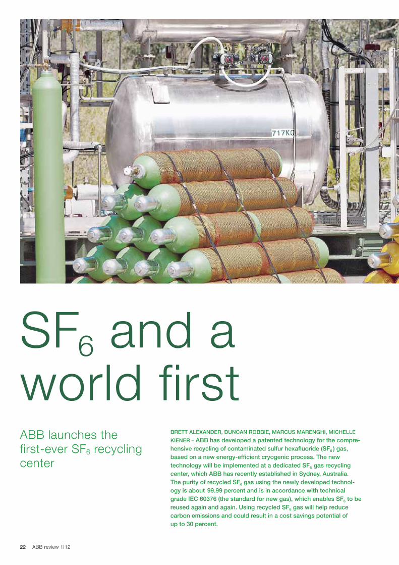
KIENER – ABB has developed a patented technology for the compre-hensive recycling of contaminated sulfur hexafluoride (SF6 ) gas, based on a new energy-efficient cryogenic process. The new technology will be implemented at a dedicated SF6 gas recycling center, which ABB has recently established in Sydney, Australia. The purity of recycled SF6 gas using the newly developed technol-ogy is about 99.99 percent and is in accordance with technical grade IEC 60376 (the standard for new gas), which enables SF6 to be reused again and again. Using recycled SF6 gas will help reduce carbon emissions and could result in a cost savings potential of up to 30 percent.
ABB launches the first-ever SF6 recycling center
SF6 and a world first
23SF6 and a world first
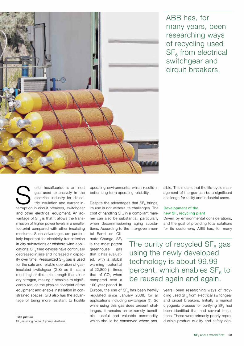
ABB has, for many years, been researching ways of recycling used SF6 from electrical switchgear and circuit breakers.
sible. This means that the life-cycle man-agement of the gas can be a significant challenge for utility and industrial users.
Development of the new SF6 recycling plantDriven by environmental considerations, and the goal of providing total solutions for its customers, ABB has, for many
years, been researching ways of recy-cling used SF6 from electrical switchgear and circuit breakers. Initially a manual cryogenic process for purifying SF6 had been identified that had several limita-tions. These were primarily poorly repro-ducible product quality and safety con-
operating environments, which results in better long-term operating reliability.
Despite the advantages that SF6 brings, its use is not without its challenges. The cost of handling SF6 in a compliant man-ner can also be substantial, particularly when decommissioning aging substa-tions. According to the Intergovernmen-tal Panel on Cli-mate Change, SF6 is the most potent greenhouse gas that it has evaluat-ed, with a global warming potential of 22,800 [1] times that of CO2 when compared over a 100-year period. In Europe, the use of SF6 has been heavily regulated since January 2008, for all applications including switchgear [2]. So while using this gas does present chal-lenges, it remains an extremely benefi-cial, useful and valuable commodity, which should be conserved where pos-
S ulfur hexafluoride is an inert gas used extensively in the electrical industry for dielec-tric insulation and current in-
terruption in circuit breakers, switchgear and other electrical equipment. An ad-vantage of SF6 is that it allows the trans-mission of higher power levels in a smaller footprint compared with other insulating mediums. Such advantages are particu-larly important for electricity transmission in city substations or offshore wind appli-cations. SF6 filled devices have continually decreased in size and increased in capac-ity over time. Pressurized SF6 gas is used for the safe and reliable operation of gas-insulated switchgear (GIS) as it has a much higher dielectric strength than air or dry nitrogen, making it possible to signifi-cantly reduce the physical footprint of the equipment and enable installation in con-strained spaces. GIS also has the advan-tage of being more resistant to hostile
The purity of recycled SF6 gas using the newly developed technology is about 99.99 percent, which enables SF6 to be reused again and again.
Title picture SF6 recycling center, Sydney, Australia
24 ABB review 1|12
testing using SF6 went ahead. These tests allowed the process parameter models to be refined, and also proved that the technology is capable of sepa-rating out contaminants from SF6.
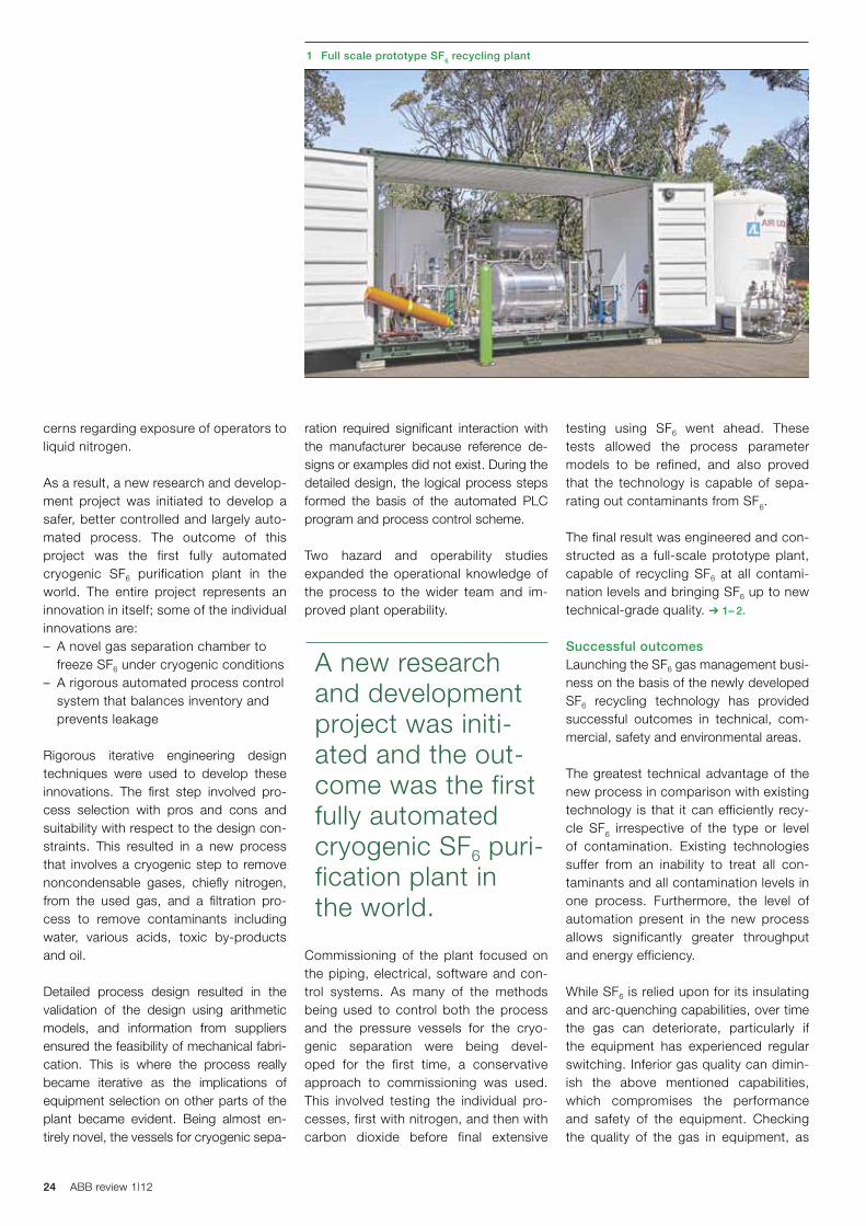
The final result was engineered and con-structed as a full-scale prototype plant, capable of recycling SF6 at all contami-nation levels and bringing SF6 up to new technical-grade quality. ➔ 1– 2.
Successful outcomesLaunching the SF6 gas management busi-ness on the basis of the newly developed SF6 recycling technology has provided successful outcomes in technical, com-mercial, safety and environmental areas.
The greatest technical advantage of the new process in comparison with existing technology is that it can efficiently recy-cle SF6 irrespective of the type or level of contamination. Existing technologies suffer from an inability to treat all con-taminants and all contamination levels in one process. Furthermore, the level of automation present in the new process allows significantly greater throughput and energy efficiency.
While SF6 is relied upon for its insulating and arc-quenching capabilities, over time the gas can deteriorate, particularly if the equipment has experienced regular switching. Inferior gas quality can dimin-ish the above mentioned capabilities, which compromises the performance and safety of the equipment. Checking the quality of the gas in equipment, as
ration required significant interaction with the manufacturer because reference de-signs or examples did not exist. During the detailed design, the logical process steps formed the basis of the automated PLC program and process control scheme.
Two hazard and operability studies expanded the operational knowledge of the process to the wider team and im-proved plant operability.
Commissioning of the plant focused on the piping, electrical, software and con-trol systems. As many of the methods being used to control both the process and the pressure vessels for the cryo-genic separation were being devel- oped for the first time, a conservative approach to commissioning was used. This involved testing the individual pro-cesses, first with nitrogen, and then with carbon dioxide before final extensive
cerns regarding exposure of operators to liquid nitrogen.
As a result, a new research and develop-ment project was initiated to develop a safer, better controlled and largely auto-mated process. The outcome of this project was the first fully automated cryogenic SF6 purification plant in the world. The entire project represents an innovation in itself; some of the individual innovations are:– A novel gas separation chamber to
freeze SF6 under cryogenic conditions– A rigorous automated process control
system that balances inventory and prevents leakage
Rigorous iterative engineering design techniques were used to develop these innovations. The first step involved pro-cess selection with pros and cons and suitability with respect to the design con-straints. This resulted in a new process that involves a cryogenic step to remove noncondensable gases, chiefly nitrogen, from the used gas, and a filtration pro-cess to remove contaminants including water, various acids, toxic by-products and oil.
Detailed process design resulted in the validation of the design using arithmetic models, and information from suppliers ensured the feasibility of mechanical fabri-cation. This is where the process really became iterative as the implications of equipment selection on other parts of the plant became evident. Being almost en-tirely novel, the vessels for cryogenic sepa-
1 Full scale prototype SF6 recycling plant
A new research and development project was initi-ated and the out-come was the first fully automated cryogenic SF6 puri-fication plant in the world.
25SF6 and a world first
standard using ABB’s new patented recy-cling process and technology.
The process is designed so that no loss of SF6 occurs at any stage of operation. Specialist detection instrumentation in combination with an automated process control system is used to detect and pre-vent leakage that may result through either operator or plant fault.
To ensure safety, all plant processes have been internalized to prevent human expo-sure and eliminate the chance of acciden-tal exposure to liquid nitrogen. Removal of other nongaseous contaminants is done with solid-state absorbents that are con-tained within high-pressure demountable housings through which the SF6 passes. The solid waste products, now safely concentrated and contained, can be dis-posed of without human contact or envi-ronmental exposure. Finally, the recycling plant is operated almost entirely automat-ically in order reduce the risk of operator error and to maximize safety.
ABB’s complete solution assists compa-nies in reducing their environmental im-pact and lowers the costs associated with administration and inventory man-agement of SF6. The new service offering will see contaminated SF6 gas recycled into technical grade standard (according to IEC 60376) for reuse. This allows the product life cycle of SF6 to be closed and removes the need for energy-intensive incineration and also provides a viable route for utilities to decrease their stored stockpiles of contaminated SF6 ➔ 3.
part of a preventative maintenance pro-gram, can extend the product life.
ABB’s fully qualified and accredited tech-nicians are equipped to safely analyze and manage existing gas inventory, and to complete inspections and tests on gas quality and quantity. The gas quality inspections ensure the purity of gas in equipment exceeds the minimum stan-dards required for safe operation. As a leading manufacturer of gas-insulated equipment and with its focus on safety, ABB has gained extensive experience in the safe handling of this gas.
It can sometimes be the case that some customers hold unwanted, nonconforming or contaminated SF6 that is no longer re-quired due to the cost, or lack, of removal options. As part of ABB’s commitment to helping customers reduce their environ-mental impact, the recycling center will ac-cept any quantity or quality of SF6 for puri-fying and restoration to a technical grade
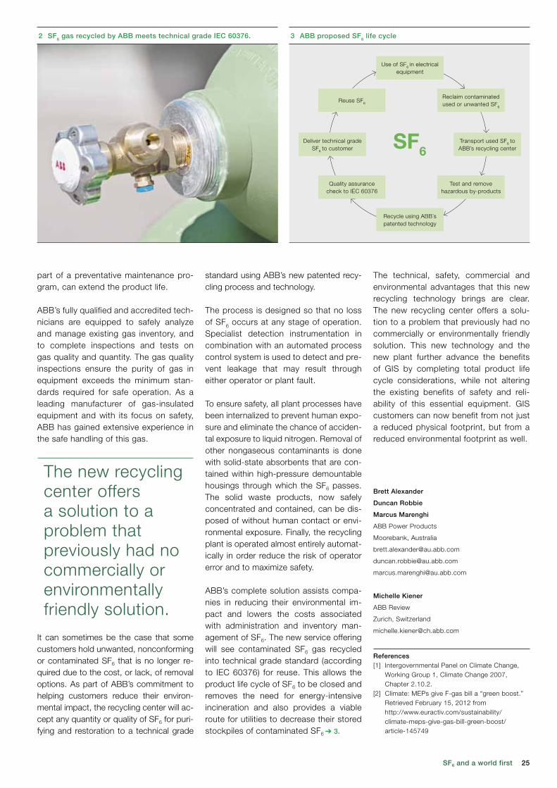
2 SF6 gas recycled by ABB meets technical grade IEC 60376.
Brett Alexander
Duncan Robbie
Marcus Marenghi
ABB Power Products
Moorebank, Australia
Michelle Kiener
ABB Review
Zurich, Switzerland
References[1] Intergovernmental Panel on Climate Change,
Working Group 1, Climate Change 2007, Chapter 2.10.2.
[2] Climate: MEPs give F-gas bill a “green boost.” Retrieved February 15, 2012 from http://www.euractiv.com/sustainability/climate-meps-give-gas-bill-green-boost/article-145749
The new recycling center offers a solution to a problem that previously had no commercially or environmentally friendly solution.
The technical, safety, commercial and environmental advantages that this new recycling technology brings are clear. The new recycling center offers a solu-tion to a problem that previously had no commercially or environmentally friendly solution. This new technology and the new plant further advance the benefits of GIS by completing total product life cycle considerations, while not altering the existing benefits of safety and reli-ability of this essential equipment. GIS customers can now benefit from not just a reduced physical footprint, but from a reduced environmental footprint as well.
3 ABB proposed SF6 life cycle
SF6
Use of SF6 in electrical equipment
Deliver technical grade SF6 to customer
Transport used SF6 to ABB’s recycling center
Reuse SF6
Reclaim contaminatedused or unwanted SF6
Quality assurancecheck to IEC 60376
Test and removehazardous by-products
Recycle using ABB´spatented technology

26 ABB review 1|12
27Eliminating downtime
it suitable for even large industrial pro-cesses. The energy storage medium itself can be state-of-the-art ultracapaci-tor modules or lead acid batteries.
What is revolutionary about the UPS-I?The three main innovations around the UPS-I are:– High efficiency– Fast utility disconnect– Revolutionary storage
A BB’s UPS-I is a new genera-tion, line-interactive power protection product that pro-tects customers’ loads dur-
ing outages and major voltage distur-bances. Such events can be caused by faults in the electricity network and, more commonly, weather events such as lightning.
The UPS-I is a particularly good solution for recloser events, deep voltage sags (dips) or swells and it supports critical loads until the utility voltage returns to within specification or a standby genera-tor starts. The length of the backup time is dependent on the power requirement of the load and the capacity of the stor-age system. The UPS-I range has mod-els up to 2.4 MVA at low voltage, making
SOPHIE BENSON-WARNER – In an industrial world in which even a few minutes of production outage has significant cost impact, it is essential to keep power flowing to machinery during periods of power grid instability. The ABB PCS100 UPS-I (Industrial Uninterruptable Power Supply) is gaining market share as a high- performance power protection solution that is capable of meeting CAPEx targets while beating traditional systems in the ongoing battle to maximize product yield and productivity as well as reduce downtime.
Keeping the power flowing during grid instabilities
Eliminating downtime
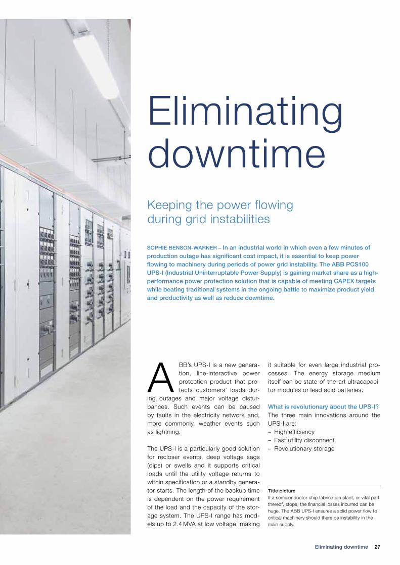
Title picture If a semiconductor chip fabrication plant, or vital part thereof, stops, the financial losses incurred can be huge. The ABB UPS-I ensures a solid power flow to critical machinery should there be instability in the main supply.
28 ABB review 1|12
Revolutionary storage
Battery and ultracapacitor storage op-tions are available for the UPS-I prod-uct ➔ 2. Although batteries have been around for a long time, the UPS-I is designed to operate with the latest low impedance spiral-wound sealed lead acid batteries, which provide very high energy density and have only a small system footprint.
The batteries for a 30 s 2.4 MVA system take up only eight 800 mm2 square stor-age enclosures – an unprecedented com-pactness.
The ultracapacitor storage option is ideal for high-reliability applications where short duration backup is required (typi-cally 3 s). Ultracapacitors have exception-ally low impedance, which means an even higher energy density and reduced foot-print. The life span is up to 15 years and a 2.4 MVA system will require only four 800 mm2 square storage enclosures.
Redundant operationThe UPS-I uses a redundant array of modular inverter systems that are capa-ble of operation at reduced power with up to 50 percent of modules unavailable. The inverter redundancy and the very short time required to replace a faulty module combine to provide an extremely high level of system availability.
CAPEx and OPEx comparisonThe UPS-I typically requires less than a quarter of the footprint of a legacy UPS, which equates to significant savings in upfront building costs, with savings con-tinuing throughout the operating life of the system. It also requires about an eighth of
The UPS-I has an efficiency of greater than 99 percent for 380 V to 480 V models and greater than 98 percent for 208 V and 200 V models.
High efficiency
The ABB UPS-I has an efficiency of greater than 99 percent for all 380 to 480 V models and greater than 98 per-cent for 208 and 200 Volt models.
This is revolutionary in the industry as legacy solutions typically exhibit 92 to 95 percent efficiency at full load and this percentage decreases with reduced load. The UPS-I has a minimal drop in efficiency down to 25 percent load.
The high efficiency of the UPS-I stems from its “offline” design. In normal opera-tion, the inverters and coupling transform-er are ready but are not carrying any load current; the only component carrying the load current is the utility disconnect, a high-efficiency SCR (silicon-controlled rectifier) switch. In the legacy double-con-version UPS system design, the rectifier and inverter are carrying and converting the entire load current, which has a major impact on the efficiency. From the begin-ning, the UPS-I design concept was to maximize efficiency by moving beyond traditional design concepts.
Fast utility disconnect
Silicon-controlled rectifiers (SCRs) are used in the UPS-I to disconnect the load from the utility during a power quality event. It is a known characteristic of these rugged, high-power switching semiconductors that removing the gate drive voltage is not always sufficient to turn off the device as the device current must reduce to zero. The UPS-I actively commutates the SCRs by using the in-verters to inject current when a power quality event is detected, thus forcing the SCR current to zero.
2 Increasing capacity1 UPS-I: single-line diagram
Ultracapacitors, also called super capacitors or double-layer capacitors, were first developed in 1957, though it was another 20 years before any significant commercialization of the technology took place. Indeed, in the intervening years, the underlying science was almost forgotten and then “rediscovered.” In the mid-1990s advances in materials and refinement of the existing systems led to improved performance and reduced costs.
This development has allowed ultracapacitors to compete with existing technologies, such as electrolytic capacitors and flywheels, and batteries in certain applications. The batteries used in the UPS-I are a refinement of existing technology. The batteries incorporate a spiral plate design that allows a very low cell resistance, so they are capable of providing large amounts of current for a short time, making them ideal for short-term storage requirements.
Input
Utility disconnect
Battery option Ultra cap storage
Inverter
Couplingtransformer
UPS-I
Output
29Eliminating downtime
The UPS-I has been well received and accepted for its performance in the semiconductor market. It has already supported many of the world’s largest memory and flat-panel-display compa-nies in delivering continuous power per-formance and reliability while having minimal environmental impact.
The product’s strengths are its efficien-cy, reliability, life span, small footprint and high power rating in a single UPS system (up to 2.4 MW). User benefits are: protection against short outages as well as deep sags; backup during generator start-up following a utility supply failure; and allowing process loads to ride through common power problems leading to increased yield, reduced product wastage and increased productivity.
The benefits of the UPS-I outclass other offerings available on the market and with continuous improvement it will meet an ever-increasing appetite of customer demands.
For more information on ABB’s PCS100 UPS-I solution, please see “Power fitness“ on page 30 of this issue of ABB Review.
UPS-I in operationThe innovative features of the UPS-I ➔ 2
were highlighted by a project to stabilize the power supply for one of Malaysia’s largest and longest-established manu-facturers of semiconductor products. As a high-tech company, they employ sophisticated equipment and this tends to be very sensitive to instabilities in the power supply. They have continually been confronted with loss of production and revenue caused by power fluctua-tions. Losses can be as high as the cost of resuming operations, and scrapping damaged products can amount to mil-lions of dollars. Six 900 kVA UPS-I units were supplied and installed, and these successfully eliminated voltage distur-bances, resulting in a disruption-free production process.
There have been many UPS-I projects and customers in South Korea, Switzer-land, Sweden and the United States. The prototype was installed in 2008 and the first project of four 300 kVA units was sold to South Korea in 2009. The product is employed in carbon fiber manufacturing in the aerospace indus-try, data centers, cable manufacturing, semiconductor fabs, and food and beverage and high-speed packaging operations.
Over seventy 1500 kVA systems have been supplied to the semiconductor industry in Asia alone. In Europe, the UPS-I is generating significant new business in the data center market and in general industry.
the air-conditioning of a legacy system, thus massively reducing greenhouse gas production.
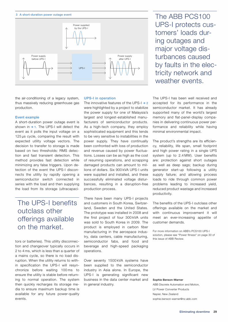
Event exampleA short-duration power outage event is shown in ➔ 1. The UPS-I will detect the event as it polls the input voltage on a 125 µs cycle, comparing the result with expected utility voltage vectors. The decision to transfer to storage is made based on two thresholds: RMS detec-tion and fast transient detection. This method provides fast detection while minimizing any false triggers. Upon de-tection of the event the UPS-I discon-nects the utility by rapidly opening a semiconductor switch connected in series with the load and then supplying the load from its storage (ultracapaci-
tors or batteries). This utility disconnec-tion and changeover typically occurs in 2 to 4 ms, which is less than a quarter of a mains cycle, so there is no load dis-ruption. When the utility returns to with-in specification the UPS-I will resyn-chronize before waiting 100 ms to ensure the utility is stable before return-ing to normal operation. The system then quickly recharges its storage me-dia to ensure maximum backup time is available for any future power-quality events.
Sophie Benson-Warner
ABB Discrete Automation and Motion,
LV Power Converter Products
Napier, New Zealand
The ABB PCS100 UPS-I protects cus-tomers’ loads dur-ing outages and major voltage dis-turbances caused by faults in the elec-tricity network and weather events.
The UPS-I benefits outclass other offerings available on the market.
3 A short-duration power outage event
Power supplied by the UPS-I
Power supply before UPS-I
UPS-I
Power supply after UPS-I

30 ABB review 1|12
RALPH HOFFMANN – Industrial automation has reached very high levels of sophistication. Plants, including automobile manufac-turing units, chemical factories and semiconductor fabs, now house some very advanced technology. And this technology requires a robust and continuous public power grid. However, the grid is susceptible to unpredictable and erratic variation and interruption. Ensuring that industrial loads continue to receive a rock-solid, clean, uninterrupted flow of power, even during major grid disturbances, is where ABB’s PCS100 AVC and PCS100 UPS-I product range comes in.
Reliable voltage protection of sensitive loads
Power fitness
31Power fitness
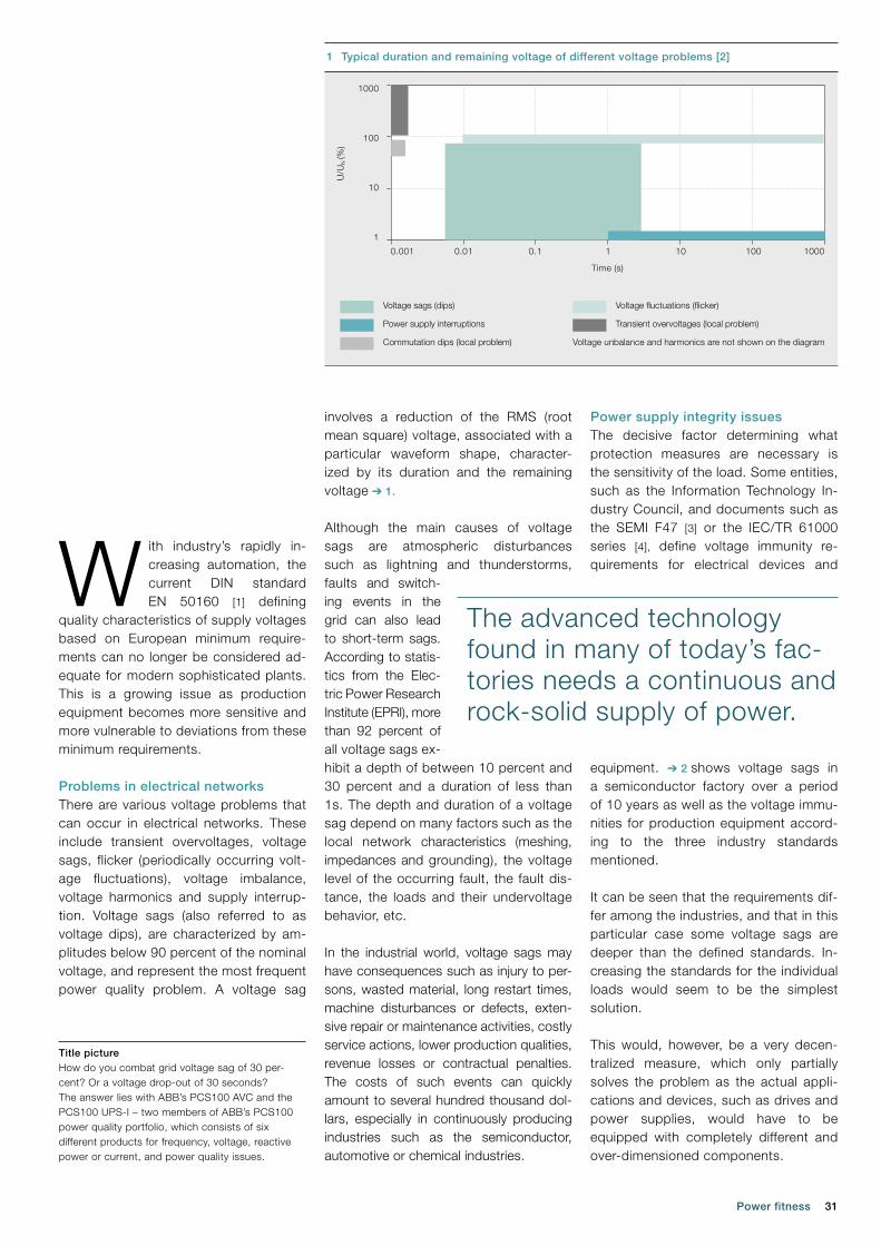
involves a reduction of the RMS (root mean square) voltage, associated with a particular waveform shape, character-ized by its duration and the remaining voltage ➔ 1.
Although the main causes of voltage sags are atmospheric disturbances such as lightning and thunderstorms, faults and switch-ing events in the grid can also lead to short-term sags. According to statis-tics from the Elec-tric Power Research Institute (EPRI), more than 92 percent of all voltage sags ex-hibit a depth of between 10 percent and 30 percent and a duration of less than 1s. The depth and duration of a voltage sag depend on many factors such as the local network characteristics (meshing, impedances and grounding), the voltage level of the occurring fault, the fault dis-tance, the loads and their undervoltage behavior, etc.
In the industrial world, voltage sags may have consequences such as injury to per-sons, wasted material, long restart times, machine disturbances or defects, exten-sive repair or maintenance activities, costly service actions, lower production qualities, revenue losses or contractual penalties. The costs of such events can quickly amount to several hundred thousand dol-lars, especially in continuously producing industries such as the semiconductor, auto motive or chemical industries.
W ith industry’s rapidly in-creasing automation, the current DIN standard EN 50160 [1] defining
quality characteristics of supply voltages based on European minimum require-ments can no longer be considered ad-equate for modern sophisticated plants. This is a growing issue as production equipment becomes more sensitive and more vulnerable to deviations from these minimum requirements.
Problems in electrical networksThere are various voltage problems that can occur in electrical networks. These include transient overvoltages, voltage sags, flicker (periodically occurring volt-age fluctuations), voltage imbalance, voltage harmonics and supply interrup-tion. Voltage sags (also referred to as voltage dips), are characterized by am-plitudes below 90 percent of the nominal voltage, and represent the most frequent power quality problem. A voltage sag
Title picture How do you combat grid voltage sag of 30 per-cent? Or a voltage drop-out of 30 seconds? The answer lies with ABB’s PCS100 AVC and the PCS100 UPS-I – two members of ABB’s PCS100 power quality portfolio, which consists of six different products for frequency, voltage, reactive power or current, and power quality issues.
1 Typical duration and remaining voltage of different voltage problems [2]
U/U
N (%
)
Time (s)
1
10
100
1000
Voltage sags (dips)
Power supply interruptions
Commutation dips (local problem)
Voltage fluctuations (flicker)
Transient overvoltages (local problem)
Voltage unbalance and harmonics are not shown on the diagram
0.01 0.1 1 10 1000.001 1000
Power supply integrity issuesThe decisive factor determining what protection measures are necessary is the sensitivity of the load. Some entities, such as the Information Technology In-dustry Council, and documents such as the SEMI F47 [3] or the IEC/TR 61000 series [4], define voltage immunity re-quirements for electrical devices and
equipment. ➔ 2 shows voltage sags in a semiconductor factory over a period of 10 years as well as the voltage immu-nities for production equipment accord-ing to the three industry standards mentioned. It can be seen that the requirements dif-fer among the industries, and that in this particular case some voltage sags are deeper than the defined standards. In-creasing the standards for the individual loads would seem to be the simplest solution.
This would, however, be a very decen-tralized measure, which only partially solves the problem as the actual appli-cations and devices, such as drives and power supplies, would have to be equipped with completely different and over-dimensioned components.
The advanced technology found in many of today’s fac-tories needs a continuous and rock-solid supply of power.
32 ABB review 1|12
Efficient protection of sensitive loadsABB’s PCS100 Power Converter Sys-tem product portfolio includes two products that offer efficient solutions for the protection of sensitive loads against voltage problems as described above: the PCS100 AVC (Active Voltage Condi-tioner) and the PCS100 UPS-I (Industri-al Uninterruptable Power Supply).
The PCS100 AVC protects sensitive indus-trial equipment and loads against voltage fluctuations and sags of up to 30 percent and 30s by corrective voltage injection. The offline UPS system PCS100 UPS-I protects processes against coming to a full stop, for example, by bridging the time required to start up diesel backup generators. It is equipped with high-per-formance, low-maintenance capacitors
or batteries and offers effective protec-tion against deep sags or power outages of up to 30s in duration.
These two power supply protection products are in use at semiconductor factories all over the world, as well as in wafer plants for photovoltaic applica-tions, in automotive processes and many other applications within the pro-cess industry.
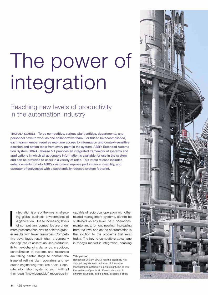
PCS100 AVC: Protection against voltage fluctuationsThe PCS100 AVC consists of two con-verter stages which are not on the cur-rent path between the load and the utili-ty ➔ 3. Instead, the corrective voltage injection is achieved by means of a transformer winding between the utility and the critical load ➔ 4. This configura-tion reduces the risk of negative impacts on the load.
Furthermore, the PCS100 AVC contains a redundant bypass system that discon-nects the AVC from the customer’s net-work under some internal fault condi-tions on the customer side. In more than 12 years of plant operation and with an installed capacity of more than 450 MVA, the platform’s bypass system has never failed. Many leading global semiconduc-tor manufacturers with particularly high demands on plant availability rely on this technology.
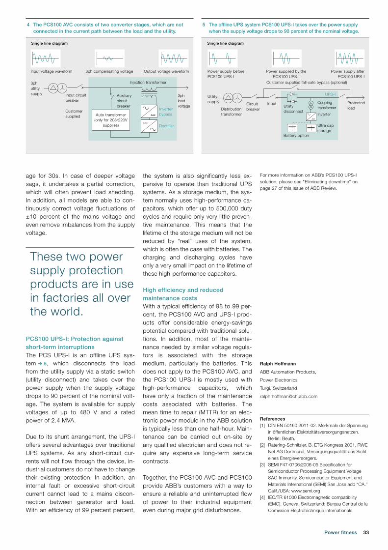
The PCS100 AVC is available with rat-ings between 160 kVA and 20 MVA either as a switchgear cabinet for low-voltage networks or containerized for medium-voltage applications. It offers online volt-age control precise to within a fraction of a second, high scalability in terms of voltage and power level, a proven and dependable converter platform, sophisti-cated control software and an efficiency of 97 to 99 percent.
The PCS100 AVC ensures quick and full correction of three-phase voltage sags down to 70 percent of the nominal voltage and of single-phase voltage sags down to 55 percent of the nominal volt-
3 The PCS100 AVC provides a platform for power quality improvements.
2 Voltage sags in a semiconductor factory over a period of 10 yearsIn
put
vol
tage
(%)
Duration (s)
0
10
20
30
40
50
60
70
80
90
100
0.10.01 1 10 100
IEC61000 Semi47 ITIC Sag data
This would require a fundamentally dif-ferent design and would make these assets considerably more expensive. Furthermore, this would not be a suit-able solution for existing plants. The second option to avoid voltage sags is to optimize the grid itself. However, the extensive protective measures involved would lead to a massive cost increase. As the voltage fluctuations are generally of a stochastic nature, and thus unpre-dictable in terms of their location and time of occurrence, the entire grid would have to be rebuilt and a different protec-tive concept would have to be imple-mented.
The most common central means to protect critical loads such as servers, computing centers and communication equipment against voltage fluctuations are dynamic UPS (uninterruptible power supply) systems and flywheel buffer sys-tems. Depending on the industry and the production process, often only 5 percent to 20 percent of the entire load of a factory is so protected due to the related high investment and operat-ing costs.
The high electrical losses of traditional dual conversion UPSs (between 4 per-cent and 8 percent) and the high main-tenance requirements associated with batteries or other storage media deter industrial companies from fully protect-ing their entire production against volt-age fluctuations. A trade-off must be made between event frequency and consequent financial impact on the one hand, and the installation and operating costs on the other.
Some real-life voltage sags are deeper than the defined standards.
33Power fitness
age for 30s. In case of deeper voltage sags, it undertakes a partial correction, which will often prevent load shedding. In addition, all models are able to con-tinuously correct voltage fluctuations of ±10 percent of the mains voltage and even remove imbalances from the supply voltage.
PCS100 UPS-I: Protection against short-term interruptionsThe PCS UPS-I is an offline UPS sys-tem ➔ 5, which disconnects the load from the utility supply via a static switch (utility disconnect) and takes over the power supply when the supply voltage drops to 90 percent of the nominal volt-age. The system is available for supply voltages of up to 480 V and a rated power of 2.4 MVA.
Due to its shunt arrangement, the UPS-I offers several advantages over traditional UPS systems. As any short-circuit cur-rents will not flow through the device, in-dustrial customers do not have to change their existing protection. In addition, an internal fault or excessive short-circuit current cannot lead to a mains discon-nection between generator and load. With an efficiency of 99 percent percent,
the system is also significantly less ex-pensive to operate than traditional UPS systems. As a storage medium, the sys-tem normally uses high-performance ca-pacitors, which offer up to 500,000 duty cycles and require only very little preven-tive maintenance. This means that the lifetime of the storage medium will not be reduced by “real” uses of the system, which is often the case with batteries. The charging and discharging cycles have only a very small impact on the lifetime of these high-performance capacitors.
High efficiency and reduced maintenance costsWith a typical efficiency of 98 to 99 per-cent, the PCS100 AVC and UPS-I prod-ucts offer considerable energy-savings potential compared with traditional solu-tions. In addition, most of the mainte-nance needed by similar voltage regula-tors is associated with the storage medium, particularly the batteries. This does not apply to the PCS100 AVC, and the PCS100 UPS-I is mostly used with high-performance capacitors, which have only a fraction of the maintenance costs associated with batteries. The mean time to repair (MTTR) for an elec-tronic power module in the ABB solution is typically less than one half-hour. Main-tenance can be carried out on-site by any qualified electrician and does not re-quire any expensive long-term service contracts.
Together, the PCS100 AVC and PCS100 provide ABB’s customers with a way to ensure a reliable and uninterrupted flow of power to their industrial equipment even during major grid disturbances.
Ralph Hoffmann
ABB Automation Products,
Power Electronics
Turgi, Switzerland
References[1] DIN EN 50160:2011-02. Merkmale der Spannung
in öffentlichen Elektrizitätsversorgungsnetzen. Berlin: Beuth.
[2] Ratering-Schnitzler, B. ETG Kongress 2001, RWE Net AG Dortmund, Versorgungsqualität aus Sicht eines Energieversorgers.
[3] SEMI F47-0706:2006-05 Specification for Semiconductor Processing Equipment Voltage SAG Immunity. Semiconductor Equipment and Materials International (SEMI) San Jose add “CA.” Calif./USA: www.semi.org
[4] IEC/TR 61000 Electromagnetic compatibility (EMC). Geneva, Switzerland: Bureau Central de la Comission Electrotechnique Internationale.
These two power supply protection products are in use in factories all over the world.
4 The PCS100 AVC consists of two converter stages, which are not connected in the current path between the load and the utility.
Single line diagram
Input voltage waveform
3phutilitysupply 3ph
loadvoltage
Inverterbypass
Rectifier
Auxiliary circuitbreaker
Injection transformer
Input circuit breaker
Customersupplied
3ph compensating voltage Output voltage waveform
Auto transformer(only for 208/220V
supplies)
For more information on ABB’s PCS100 UPS-I solution, please see “Eliminating downtime“ on page 27 of this issue of ABB Review.
5 The offline UPS system PCS100 UPS-I takes over the power supply when the supply voltage drops to 90 percent of the nominal voltage.
Single line diagram
Utilitysupply
Distributiontransformer
Circuitbreaker
Input Protectedload
Couplingtransformer
Inverter
Ultra capstorage
UPS-I
Utilitydisconnect
Battery option
Power supply beforePCS100 UPS-I
Power supplied by thePCS100 UPS-I
Customer supplied fall-safe bypass (optional)
Power supply afterPCS100 UPS-I
34 ABB review 1|12
Title pictureRefineries: System 800xA has the capability not only to integrate automation and information management systems in a single plant, but to link the systems of plants at different sites, and in different countries, into a single, integrated entity.
capable of reciprocal operation with other related management systems, cannot be sustained on any level, be it operations, maintenance, or engineering. Increasing both the level and scope of automation is the solution to the problems that exist today. The key to competitive advantage in today’s market is integration, enabling
I ntegration is one of the most challeng-ing global business environments of a generation. Due to increasing levels of competition, companies are under
more pressure than ever to achieve great-er results with fewer resources. Competi-tive advantages result when a company can tap into its assets' unused productiv-ity to meet changing demands. In addition, centralization of systems and resources are taking center stage to combat the issue of retiring plant operators and re-duced engineering resource pools. Sepa-rate information systems, each with all their own “knowledgeable” resources in-
THORALF SCHULz – To be competitive, various plant entities, departments, and personnel have to work as one collaborative team. For this to be accomplished, each team member requires real-time access to information and context-sensitive decision and action tools from every point in the system. ABB’s Extended Automa-tion System 800xA Release 5.1 provides an integrated framework of systems and applications in which all actionable information is available for use in the system and can be provided to users in a variety of roles. This latest release includes enhancements to help ABB’s customers improve performance, usability, and operator effectiveness with a substantially reduced system footprint.
Reaching new levels of productivity in the automation industry
The power of integration

35The power of integration
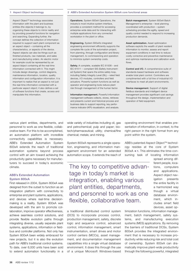
36 ABB review 1|12
operating environment that enables pre-sentation of information, in context, to the right person in the right format from any point within the system.
ABB’s patented Aspect ObjectTM technol-ogy resides at the core of System 800xA ➔ 1. This eliminates the time-con-suming task of locating information
spread among dif-ferent people, loca-tions, computers and applications. Aspect object nav-igation presents the entire facility in a harmonized way though a virtual data base environ-ment, which in-cludes smart field devices, asset op-
timization functions, information manage-ment, batch management, safety sys-tems, and manufacturing execution systems (MES) applications. By removing the barriers of traditional DCSs, System 800xA provides the integrated environ-ment that is necessary to increase pro-ductivity while reducing risk and total cost of ownership. System 800xA can dra-matically improve plant-wide productivity through the following powerful, integrated
wide variety of industries including oil, gas and petrochemical; pulp and paper; bio-tech/pharmaceutical; utility; chemical/fine chemical; metals; and mining.
System 800xA represents a single opera-tion, engineering, and information man-agement environment for an extended automation scope. It extends the reach of
a traditional distributed control system (DCS) to incorporate process control, production management, safety, discrete logic and sequence control, advanced control, information management, smart instrumentation, smart drives and motor control centers (MCCs), asset manage-ment, and documentation management capabilities into a single virtual database environment. It does this through the use of a unique Microsoft Windows-based
various plant entities, departments, and personnel to work as one flexible, collab-orative team. For this to be accomplished, an automation platform with incredible connectivity capabilities is necessary. ABB’s Extended Automation System 800xA extends the reach of traditional auto mation systems beyond process control with an aim toward achieving the productivity gains necessary for manufac-turers to succeed in today's economic climate.
ABB’s Extended Automation System 800xA First released in 2004, System 800xA was designed from the outset to function as an integration platform with connectivity to enterprise and plant systems, applications, and devices where real-time decision-making is a reality. System 800xA was developed with the aim to promote col-laboration, improve operator effectiveness, achieve seamless control solutions, and provide flexible evolution paths through integrating diverse, usually separate plant systems, applications, information or field-bus and controller platforms. Not only has System 800xA been widely embraced for new projects, but it is also the evolution path for ABB’s traditional control systems. To date, over 6,000 units have been sold to extend automation functionality in a
1 Aspect Object technology
Aspect ObjectTM technology associates information with the plant and business entities (the objects) it belongs to, by organizing these objects to mirror reality and by providing powerful functions for navigation and searching. Expanding further, the concept defines the collection of information required to support each plant component as an aspect object – containing all the characteristics, or aspects of the device. Aspect objects can also be things such as finished products, raw materials, and sales and manufacturing orders. An electric motor for example could be represented by an aspect bbject containing all the real-time information connected with it. This might include design drawings, control diagrams, maintenance information, location, quality information and configuration information. It is important to realize that an aspect is not just the real-time information connected with a particular aspect object; it also defines a set of software functions that create, access and manipulate this information.
2 ABB’s Extended Automation System 800xA core functional areas
Operations. System 800xA Operations, the industry’s most intuitive system interface, provides a consistent method for accessing enterprise-wide data and for interacting with multiple applications from any connected workstation in the plant or office.
Engineering. System 800xA’s integrated engineering environment efficiently supports the complete life-cycle of the automation project, from planning, through configuration and library management, to commissioning and operation to minimize system ownership costs.
Safety. A complete, scalable IEC 61508 – and IEC 61511 – compliant SIS (Safety Instrument-ed System) that spans the entire safety loop, including Safety Integrity Level (SIL) – rated field devices, I/O modules, controllers and field actuators. Powerful system functions as well as operator and engineering tools reduce plant risk through management of the human factor.
Information management. Powerful information management software collects, stores, retrieves and presents current and historical process and business data to support reporting, key perfor - mance indicator (KPI) visualization, and analysis.
Batch management. System 800xA Batch Management‘s enterprise – level planning coordinated with production – system scheduling provides the agility, speed and quality control needed to respond to increasing production demands.
Asset optimization. Asset optimization software exploits the wealth of plant resident information to monitor, assess and report equipment conditions in real time to reduce costly corrective and preventive maintenance and optimize maintenance and calibration work flows.
Control and I/O. A comprehensive suite of standards-based hardware and software enable total plant control. Controllers are complimented with a full line of industrial I/O interfaces to meet all plant environments.
Device management. Support of digital fieldbus standards and intelligent device management provides significant cost savings throughout the design, implementation and operation of field equipment.
The key to competitive advan-tage in today’s market is integration, enabling various plant entities, departments, and personnel to work as one flexible, collaborative team.
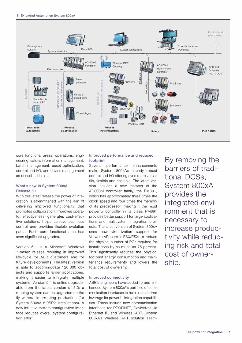
37
core functional areas: operations, engi-neering, safety, information management, batch management, asset optimization, control and I/O, and device management as described in ➔ 2.
What’s new in System 800xA Release 5.1 With this latest release the power of inte-gration is strengthened with the aim of delivering improved functionality that promotes collaboration, improves opera-tor effectiveness, generates cost-effec-tive solutions, helps achieve seamless control and provides flexible evolution paths. Each core functional area has seen significant upgrades.
Version 5.1 is a Microsoft Windows 7-based release resulting in improved life-cycle for ABB customers and for future developments. The latest version is able to accommodate 120,000 ob-jects and supports larger applications, making it easier to integrate multiple systems. Version 5.1 is online upgrade-able from the latest version of 5.0; a running system can be upgraded on the fly without interrupting production (for System 800xA 5.0SP2 installations). A new intuitive system configuration inter-face reduces overall system configura-tion effort.
The power of integration
Improved performance and reduced footprintSeveral performance enhancements make System 800xA’s already robust control and I/O offering even more versa-tile, flexible and scalable. The latest ver-sion includes a new member of the AC800M controller family, the PM891, which has approximately three times the clock speed and four times the memory of its predecessor, making it the most powerful controller in its class. PM891 provides better support for large applica-tions and multisystem integration proj-ects. The latest version of System 800xA uses new virtualization support for Vmware vSphere 4 ESX/ESXi to reduce the physical number of PCs required for installations by as much as 75 percent. This significantly reduces the physical footprint energy consumption and main-tenance requirements and lowers the total cost of ownership.
Improved connectivityABB’s engineers have added to and en-hanced System 800xA’s portfolio of com-munication interfaces to help users further leverage its powerful integration capabili-ties. These include new communication interfaces for PROFINET, DeviceNet via Ethernet IP, and WirelessHART. System 800xA’s WirelessHART solution seam-
By removing the barriers of tradi-tional DCSs, System 800xA provides the integrated envi-ronment that is necessary to increase produc-tivity while reduc-ing risk and total cost of owner-ship.
3 Extended Automation System 800xA
System workplacesExtended operatorworkplacePanel 800
Plant network,ERP, CMMS...
System networks
Field networks
AC 800Mcontroller
WirelessHARTGateway
WirelessHART
Motorcontroller
Protection &control IED
Variable-speed drive
LV switchgear
ABB and3rd partyPLC & DCS
Mod
uleb
us
IEC
6185
0
PR
OFI
BU
S /
PR
OFI
NE
T /
Mod
uleb
us /
Dev
iceN
et
PR
OFI
BU
S /
Fo
und
atio
n Fi
eld
bus
/ M
odul
ebus
MO
DB
US
AC 800Mhigh integritycontroller
Fire & gas
ShutdownS900 I/O
S800 I/O
Substationautomation
Processelectrification
Processinstrumentation PLC & DCSSafety
Base systemservers
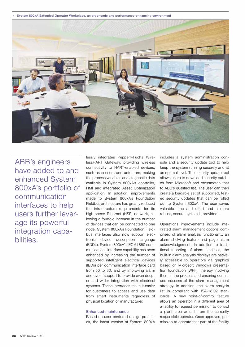
38 ABB review 1|12
includes a system administration con-sole and a security update tool to help keep the system running securely and at an optimal level. The security update tool allows users to download security patch-es from Microsoft and crossmatch that to ABB’s qualified list. The user can then create a loadable set of supported, test-ed security updates that can be rolled out to System 800xA. The user saves valuable time and effort and a more robust, secure system is provided.
Operations improvements include inte-grated alarm management options com-prised of alarm analysis functionality, an alarm shelving feature and page alarm acknowledgement. In addition to tradi-tional reporting of alarm statistics, the built-in alarm analysis displays are native-ly accessible to operators via graphics based on Microsoft Windows presenta-tion foundation (WPF), thereby involving them in the process and ensuring contin-ued success of the alarm management strategy. In addition, the alarm analysis list is compliant with ISA-18.02 stan-dards. A new point-of-control feature allows an operator in a different area of a facility to request permission to control a plant area or unit from the currently responsible operator. Once approved, per-mission to operate that part of the facility
lessly integrates Pepperl+Fuchs Wire-lessHART Gateway, providing wireless connectivity to HART-enabled devices, such as sensors and actuators, making the process variables and diagnostic data available in System 800xA’s controller, HMI and integrated Asset Optimization application. In addition, improvements made to System 800xA’s Foundation Fieldbus architecture has greatly reduced the infrastructure requirements for its high-speed Ethernet (HSE) network, al-lowing a fourfold increase in the number of devices that can be connected to one node. System 800xA’s Foundation Field-bus interfaces also now support elec-tronic device description language (EDDL). System 800xA’s IEC 61850 com-munications interface capability has been enhanced by increasing the number of supported intelligent electrical devices (IEDs) per communication interface card from 50 to 80, and by improving alarm and event support to provide even deep-er and wider integration with electrical systems. These interfaces make it easier for customers to access and use data from smart instruments regardless of physical location or manufacturer.
Enhanced maintenanceBased on user centered design practic-es, the latest version of System 800xA
ABB’s engineers have added to and enhanced System 800xA’s portfolio of communication interfaces to help users further lever-age its powerful integration capa-bilities.
4 System 800xA Extended Operator Workplace, an ergonomic and performance-enhancing environment

39The power of integration
Thoralf Schulz
ABB Process Automation
Mannheim, Germany
management processes, as it can verify that no other changes have been made except the ones present in the change request, saving hours of change request verification and testing.
System 800xA Release 5.1 improves life-cycle management through the use of the latest technology, providing more performance and usability through in-creased system sizing and a new, more powerful controller, increased energy savings, and reduced maintenance costs through footprint reduction, and im-proved operator effectiveness through integrated information and alarm man-agement. With this latest release, Sys-tem 800xA presents a unified workflow environment that enables collaboration and provides workers with an under-standing of their specific requirements in the context of the bigger picture. Sharing the data, knowledge and functional views ensures that each functional group in the plant understands the operational situation and their role in improving it. This is the level of integration delivered by ABB’s System 800xA Release 5.1, an automation platform that has the ability to engineer, commission, control and operate automation strategies for pro-cess, power, electrical, and safety in the same redundant, reliable system.
is transferred to the requesting operator and is captured in the audit trail log. The area or unit alarm and event messages are now routed to the new operator. Point of control improves the coordination of operators during critical periods, such as shift change, providing a safer, more secure operating environment.
Improved change managementSystem 800xA 5.1 includes two new fea-tures to improve and streamline change management procedures. The task analy-sis tool lets the user evaluate how his/her application will be executed based on the current task rates assigned prior to down-loading. It clearly shows any latency or conflicts and then prevents the new ap-plication from being downloaded to avoid a controller error. Performance of “what if” scenarios to pinpoint where problems may occur when modifying task execution cycle times are possible. The detailed dif-ference report provides a way to easily see changes made in control applications and graphics and provides a report of exactly what has been modified, added or removed in an easy-to-read user inter-face. The detailed difference report pro-vides the engineer and quality personnel with precisely the information needed to identify changes and evaluate their im-pact. This is especially useful in change
5 Esperanza copper-gold mine in Antofagasta, Chile, running System 800xA With this latest release, System 800xA presents a unified workflow environment that enables collabo-ration and pro-vides workers with an under-standing of their specific require-ments in the con-text of the bigger picture.

ABB review 1|12 40
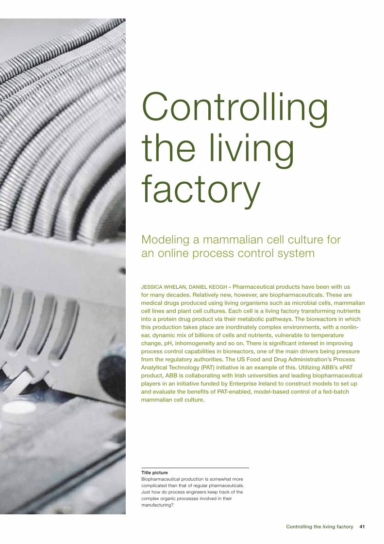
41Controlling the living factory
JESSICA WHELAN, DANIEL KEOGH – Pharmaceutical products have been with us for many decades. Relatively new, however, are biopharmaceuticals. These are medical drugs produced using living organisms such as microbial cells, mammalian cell lines and plant cell cultures. Each cell is a living factory transforming nutrients into a protein drug product via their metabolic pathways. The bioreactors in which this production takes place are inordinately complex environments, with a nonlin-ear, dynamic mix of billions of cells and nutrients, vulnerable to temperature change, pH, inhomogeneity and so on. There is significant interest in improving process control capabilities in bioreactors, one of the main drivers being pressure from the regulatory authorities. The US Food and Drug Administration’s Process Analytical Technology (PAT) initiative is an example of this. Utilizing ABB’s xPAT product, ABB is collaborating with Irish universities and leading biopharmaceutical players in an initiative funded by Enterprise Ireland to construct models to set up and evaluate the benefits of PAT-enabled, model-based control of a fed-batch mammalian cell culture.
Modeling a mammalian cell culture for an online process control system
Controlling the living factory
Title pictureBiopharmaceutical production Is somewhat more complicated than that of regular pharmaceuticals. Just how do process engineers keep track of the complex organic processes involved in their manufacturing?

42 ABB review 1|12
(CQA). The objective is to understand the processes by defining their CPPs, and to monitor them in a timely manner, preferably in-line or online, thus reduc-ing final testing requirements, reject rates and instances of over-processing while enhancing consistency and prod-uct quality.
As there is variability both in raw materi-als and in operation of equipment, a stat-ic batch process will produce a variable product. By increasing process under-standing and control potential, the PAT initiative aims to design quality into the process, rather than relying on testing the CQAs of the final product, by facili-tating a dynamic manufacturing process that can compensate for these under-lying variations. PAT has increasingly gained worldwide acceptance as a prov-en method of ensuring product safety and quality by many industry experts.
Associated benefits of greater process understanding, apart from improved product quality, include faster process optimization and speed to market, im-
proved product titers, decreased pro-cess variability, shorter cycle times and reduced waste.
PAT-facilitating instrumentationFacilitating the PAT initiative is the in-creased availability of online measure-ments. In order to effectively control a parameter, it must first be measured. Spectroscopic techniques such as near infrared (NIR), mid-IR and Raman are on-line monitoring tools for nutrient and me-tabolite concentrations. Automated multi-function analyzers such as the Nova or YSI systems use a combination of enzy-matic, amperometric, potentiometric and coulter counter or CCD camera analyzers to perform simultaneous quantification of
continuously or periodically over the course of a batch and no product is har-vested before the endpoint is reached. The improvement in productivity achieved in fed-batch processes is due mainly to an increase in the integral of viable cells and a resultant increase in volumetric productivity. Fed-batch mode is popular because of reliability, ease of scale-up, significant increase in production levels and ease of process characterization and validation.
Controlling the processIn contrast to the chemical and traditional pharmaceutical sectors, process control for bioprocesses is in its infancy due, in part, to the challenges associated with bioreactor control: complex growth media, inadequate measurement of rele-vant process parameters, the limited and noisy nature of experimental data and difficulties inherent in controlling biopro-cesses, which are dynamic, complex and nonlinear. Process control of bioreactors seeks to influence the individual complex intracellular reactions of billions of cells by controlling their extracellular environ-ment [2]. Tradition-ally, parameters such as tempera-ture, pH and dis-solved oxygen (DO) are measured us-ing in-situ probes and are controlled using PID loops to adjust gas or alkali flows. Control of nutrient levels is still usually manual. Generally, bolus feeds are intro-duced at 24-hour intervals based on offline analysis of daily process samples and a priori process knowledge.
Improving control – the PAT initiativeCurrently, there is significant interest in improving the process control capabili-ties of bioreactors. One of the main driv-ers for this is pressure from the regula-tory authorities. In 2003, the US Food and Drug Administration (FDA) launched the Process Analytical Technology (PAT) initiative. The FDA defines PAT as a mechanism to design, analyze, and control pharmaceutical manufacturing processes through the measurement of critical process parameters (CPP), which affect critical quality attributes
I n contrast to pharmaceuticals, which may be thought of as being “chemical” based, biopharmaceuti-cals are medical drugs produced by
(but not simply extracted from) living organisms. The science is relatively new and it was only in 1982 that one of the first products, biosynthetic “human” in-sulin made via recombinant DNA tech-nology, came on to the market. Since then, the biopharmaceutical sector has become a significant and growing divi-sion of the pharmaceutical industry. The number of biopharmaceuticals currently on the market is just in excess of 200 and in 2009 they generated $99 billion in sales. The market is predicted to grow by between seven and 15 percent annually over the next several years, and by 2013 four of the five top-selling drugs will be protein-based products. Mammalian cells, particularly Chinese hamster ovary (CHO) cells, and bacterial systems, such as Escherichia coli (E. coli), produce the bulk of the products on the market but alternative systems such as yeast and plant cells are also used [1].
Fed-batch mode The vast majority of current industrial bioprocesses are operated in batch or fed-batch mode. Fed-batch mode refers to a process whereby a concentrated nutrient feed solution is added either
The market is predicted to grow between seven and 15 percent annually over the next several years, and by 2013 four of the five top- selling drugs will be protein-based products.
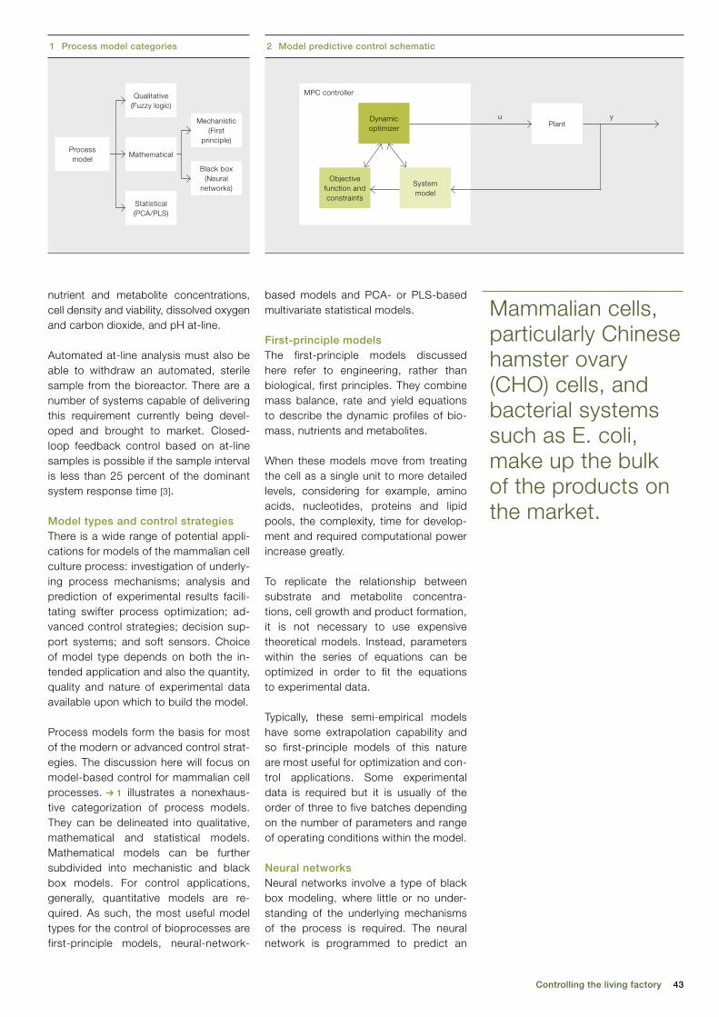
43Controlling the living factory
based models and PCA- or PLS-based multivariate statistical models.
First-principle models The first-principle models discussed here refer to engineering, rather than biological, first principles. They combine mass balance, rate and yield equations to describe the dynamic profiles of bio-mass, nutrients and metabolites.
When these models move from treating the cell as a single unit to more detailed levels, considering for example, amino acids, nucleotides, proteins and lipid pools, the complexity, time for develop-ment and required computational power increase greatly. To replicate the relationship between substrate and metabolite concentra-tions, cell growth and product formation, it is not necessary to use expensive theoretical models. Instead, parameters within the series of equations can be optimized in order to fit the equations to experimental data.
Typically, these semi-empirical models have some extrapolation capability and so first-principle models of this nature are most useful for optimization and con-trol applications. Some experimental data is required but it is usually of the order of three to five batches depending on the number of parameters and range of operating conditions within the model.
Neural networks Neural networks involve a type of black box modeling, where little or no under-standing of the underlying mechanisms of the process is required. The neural network is programmed to predict an
nutrient and metabolite concentrations, cell density and viability, dissolved oxygen and carbon dioxide, and pH at-line.
Automated at-line analysis must also be able to withdraw an automated, sterile sample from the bioreactor. There are a number of systems capable of delivering this requirement currently being devel-oped and brought to market. Closed-loop feedback control based on at-line samples is possible if the sample interval is less than 25 percent of the dominant system response time [3].
Model types and control strategiesThere is a wide range of potential appli-cations for models of the mammalian cell culture process: investigation of underly-ing process mechanisms; analysis and prediction of experimental results facili-tating swifter process optimization; ad-vanced control strategies; decision sup-port systems; and soft sensors. Choice of model type depends on both the in-tended application and also the quantity, quality and nature of experimental data available upon which to build the model.
Process models form the basis for most of the modern or advanced control strat-egies. The discussion here will focus on model-based control for mammalian cell processes. ➔ 1 illustrates a nonexhaus-tive categorization of process models. They can be delineated into qualitative, mathematical and statistical models. Mathematical models can be further subdivided into mechanistic and black box models. For control applications, generally, quantitative models are re-quired. As such, the most useful model types for the control of bioprocesses are first-principle models, neural-network-
Mammalian cells, particularly Chinese hamster ovary (CHO) cells, and bacterial systems such as E. coli, make up the bulk of the products on the market.
1 Process model categories
Qualitative(Fuzzy logic)
MathematicalProcess model
Statistical(PCA/PLS)
Mechanistic(First
principle)
Black box(Neural
networks)
2 Model predictive control schematic
PlantDynamicoptimizer
Systemmodel
Objectivefunction andconstraints
MPC controller
yu
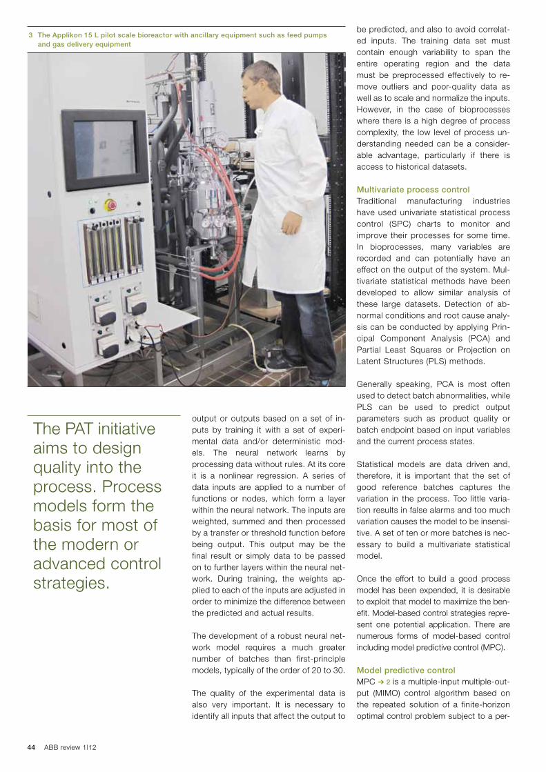
44 ABB review 1|12
be predicted, and also to avoid correlat-ed inputs. The training data set must contain enough variability to span the entire operating region and the data must be preprocessed effectively to re-move outliers and poor-quality data as well as to scale and normalize the inputs. However, in the case of bioprocesses where there is a high degree of process complexity, the low level of process un-derstanding needed can be a consider-able advantage, particularly if there is access to historical datasets.
Multivariate process controlTraditional manufacturing industries have used univariate statistical process control (SPC) charts to monitor and improve their processes for some time. In bioprocesses, many variables are recorded and can potentially have an effect on the output of the system. Mul-tivariate statistical methods have been developed to allow similar analysis of these large datasets. Detection of ab-normal conditions and root cause analy-sis can be conducted by applying Prin-cipal Component Analysis (PCA) and Partial Least Squares or Projection on Latent Structures (PLS) methods.
Generally speaking, PCA is most often used to detect batch abnormalities, while PLS can be used to predict output parameters such as product quality or batch endpoint based on input variables and the current process states.
Statistical models are data driven and, therefore, it is important that the set of good reference batches captures the variation in the process. Too little varia-tion results in false alarms and too much variation causes the model to be insensi-tive. A set of ten or more batches is nec-essary to build a multivariate statistical model.
Once the effort to build a good process model has been expended, it is desirable to exploit that model to maximize the ben-efit. Model-based control strategies repre-sent one potential application. There are numerous forms of model-based control including model predictive control (MPC).
Model predictive controlMPC ➔ 2 is a multiple-input multiple-out-put (MIMO) control algorithm based on the repeated solution of a finite-horizon optimal control problem subject to a per-
output or outputs based on a set of in-puts by training it with a set of experi-mental data and/or deterministic mod-els. The neural network learns by pro cessing data without rules. At its core it is a nonlinear regression. A series of data inputs are applied to a number of functions or nodes, which form a layer within the neural network. The inputs are weighted, summed and then processed by a transfer or threshold function before being output. This output may be the final result or simply data to be passed on to further layers within the neural net-work. During training, the weights ap-plied to each of the inputs are adjusted in order to minimize the difference between the predicted and actual results.
The development of a robust neural net-work model requires a much greater number of batches than first-principle models, typically of the order of 20 to 30. The quality of the experimental data is also very important. It is necessary to identify all inputs that affect the output to
The PAT initiative aims to design quality into the process. Process models form the basis for most of the modern or advanced control strategies.
3 The Applikon 15 L pilot scale bioreactor with ancillary equipment such as feed pumps and gas delivery equipment

45Controlling the living factory
instantaneous error between process variable and setpoint, the longer view taken by MPC reduces the impact of un-known disturbances, erratic signals and noise. MPC can also deal well with sys-tems with a long dead time, though it is not robust in situations where the dead time changes significantly.
MPC is inherently suited to optimization. The presence of a dynamic optimizer, ob-jective function and constraints within the framework means that MPC can predict future violations of constraints, handle complex interactions and smoothly adjust the manipulated variables. MPC has the widest application of all advanced control strategies in industrial applications.
The apPAT projectCurrently, a project to investigate the potential of the bio-application of PAT is underway. Funded by Enterprise Ireland and led by Professor Brian Glennon in the School of Chemical and Bioprocess Engineering at University College Dublin, research groups at UCD, Dublin City Uni-versity, the Tyndall Institute at University College Cork and the National Institute for Bioprocessing Research and Training (NIBRT) are collaborating with ABB to set up and evaluate the benefits of PAT- enabled, model-based control of a fed-batch mammalian cell culture. A number of Irish-based multinationals such as Pfizer, Eli Lilly, Jannsen Biologics and Merck as well as a group of indigenous SMEs including BioUETIKON, Techno-path and BioImages, among others, form
an industrial advi-sory board that meets quarterly to comment on and guide the research strands.
The project is based on an ABB Exhended Auto-mation System 800xA control sys-tem and an xPAT
system comprised of FTSW800 ana- lyzer controllers and data management system.
An industry-specific application built on the System 800xA infrastructure, xPAT (Industrial IT eXtended PAT) is a next-generation PAT solution that harnesses the System 800xA operations and engi-
formance specification, constraints on states and inputs, and a system model. It can use a mathematical model such as first principle or neural network models, or statistical models such as PCA or PLS
to create a future trajectory of the batch based on multiple measured process in-puts. It seeks to minimize the square of the error between the predicted trajec-tory and desired trajectory over a user-defined prediction horizon and then cal-culates a controller action for each of its outputs. In contrast to a traditional PID controller, which aims to minimize the
The longer view taken by MPC reduces the impact of unknown distur-bances, erratic signals and noise. MPC can also deal well with systems with a large dead time.
Statistical models can be used as an aid for online pro-cess evaluation and decision making, as well as a tool for identifying variables likely to be responsible for deviations.
Chinese hamster ovary cell lines are the workhorses of the mammalian cell biophar-maceutical industry. They are used to manufacture a number of licensed therapeutic proteins such as erythropoietin (EPO), CD20, tumor necrosis factor alpha and HER2. They are robust cells, which can easily be adapted to meet the requirements of large-scale protein production.
They are easily adapted to grow in suspen-sion at high viable cell densities, which simplifies large-scale culture in stirred tank bioreactors. They are also capable of high levels of protein expression. Also, their DNA is easily modified in order to have the cell line produce the protein product of interest.
4 CHO cell lines
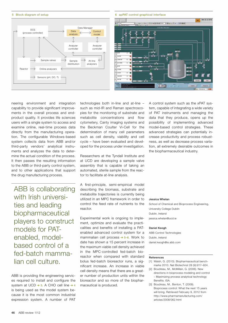
46 ABB review 1|12
A control system such as the xPAT sys-tem, capable of integrating a wide variety of PAT instruments and managing the data that they produce, opens up the possibility of implementing advanced model-based control strategies. These advanced strategies can potentially in-crease productivity and process robust-ness, as well as decrease process varia-tion, all extremely desirable outcomes in the biopharmaceutical industry.
Jessica Whelan
School of Chemical and Bioprocess Engineering,
University College Dublin
Dublin, Ireland
Daniel Keogh
ABB Control Technologies
Dublin, Ireland
References[1] Walsh, G. (2010). Biopharmaceutical bench-
marks 2010. Nat Biotechnol 28 (9):917–924.[2] Boudreau, M., McMillan, G. (2006). New
directions in bioprocess modeling and control – Maximizing process analytical technology Benefits. ISA.
[3] Boudreau, M., Benton, T. (2008). Bioprocess control: What the next 15 years will bring. Retrieved February 9, 2012 from http://www.pharmamanufacturing.com/articles/2008/062.html
technologies both in-line and at-line – such as mid-IR and Raman spectrosco-pies for the monitoring of substrate and metabolite concentrations and flow cytometery, Canty imaging systems and the Beckman Coulter Vi-Cell for the determination of many cell parameters such as cell density, viability and cell cycle – have been evaluated and devel-oped for the process under investigation.
Researchers at the Tyndall Institute and at UCD are developing a sample valve assembly that is capable of taking an auto mated, sterile sample from the reac-tor to facilitate at-line analysis.
A first-principle, semi-empirical model describing the biomass, substrate and metabolite trajectories is currently being utilized in an MPC framework in order to control the feed rate of nutrients to the reactor.
Experimental work is ongoing to imple-ment, optimize and evaluate the practi-calities and benefits of installing a PAT-enabled advanced control system for a mammalian cell process ➔ 5–6. Work to date has shown a 15 percent increase in the maximum viable cell density achieved in the MPC-controlled fed-batch bio-reactor when compared with standard bolus fed-batch bioreactor runs, a sig-nificant increase. An increase in viable cell density means that there are a great-er number of production units within the bioreactor and so more of the biophar-maceutical is produced.
neering environment and integration capability to provide significant improve-ments in the overall process and end-product quality. It provides life sciences users with a single system to access and examine online, real-time process data directly from the manufacturing opera-tion. The configurable Windows-based system collects data from ABB and/or third-party vendors’ analytical instru-ments and analyzes the data to deter-mine the actual condition of the process. It then passes the resulting information to the ABB or third-party control system, and to other applications that support the drug manufacturing process.
ABB is providing the engineering servic-es required to install and configure the system at UCD ➔ 3. A CHO cell line ➔ 4 is being used as the model system be-cause it is the most common industrial expression system. A number of PAT
5 Block diagram of setup 6 apPAT control graphical interface
DCS(process controller)
Reactor
Sample valves Sample distribution
At-line analyzers
Online analyzers
Sensors (pH, DO, T)
Data Manager
Analyzercontroller
Analyzercontroller
ABB is collaborating with Irish universi-ties and leading biopharmaceutical players to construct models for PAT- enabled, model-based control of a fed-batch mamma-lian cell culture.
Data analysis
Controlmodel

47
MARIO HOERNICKE, PHILLIP WEEMES, HEINO HANKING –
Computer simulation is a valuable tool whose importance is growing in all areas of engineering. In industrial control, simulation is an effective way to minimize effort for test preparation, provide imitations of comprehensive systems under test, enable the systems to be properly dynamically tested on the shop floor and, hence, to reduce changes to device applications during the commissioning effort and so ultimately reduce plant downtime. Simulation is a standard part of the factory acceptance test (FAT) of control sys-tems, and is also used for operator training. For fieldbuses and fieldbus systems such as Foundation Fieldbus (FF),
however, this simulation ability is lacking. The FAT can be performed for sample loops but not for complete installed solutions with their complex interactions and distributed control functionality. Because FF devices can execute control loops, the FAT technique used is error prone and does not guarantee correct functional behavior of the entire system. To address this, the development of an FF simulator was launched. The technology is making it possible to dynamically test control-in-the-field applications for FF during FAT. This article looks at the technical challenges that had to be solved as well as the architecture and resulting technology of the Soft FF.
Soft FF reduces commissioning effort by simulating Foundation Fieldbus
The fieldbus outside the field
The fieldbus outside the field
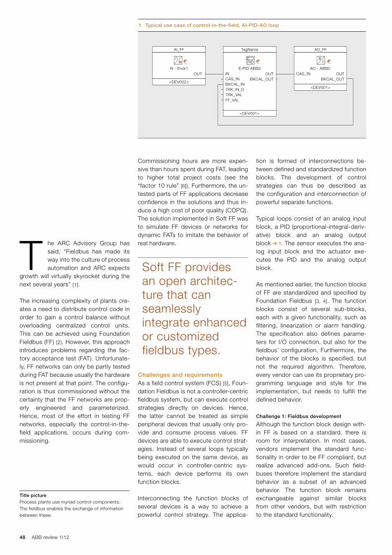
48 ABB review 1|12
tion is formed of interconnections be-tween defined and standardized function blocks. The development of control strategies can thus be described as the configuration and interconnection of powerful separate functions.
Typical loops consist of an analog input block, a PID (proportional-integral-deriv-ative) block and an analog output block ➔ 1. The sensor executes the ana-log input block and the actuator exe-cutes the PID and the analog output block.
As mentioned earlier, the function blocks of FF are standardized and specified by Foundation Fieldbus [3, 4]. The function blocks consist of several sub-blocks, each with a given functionality, such as filtering, linearization or alarm handling. The specification also defines parame-ters for I/O connection, but also for the fieldbus’ configuration. Furthermore, the behavior of the blocks is specified, but not the required algorithm. Therefore, every vendor can use its proprietary pro-gramming language and style for the implementation, but needs to fulfill the defined behavior.
Challenge 1: Fieldbus development
Although the function block design with-in FF is based on a standard, there is room for interpretation. In most cases, vendors implement the standard func-tionality in order to be FF compliant, but realize advanced add-ons. Such field-buses therefore implement the standard behavior as a subset of an advanced behavior. The function block remains exchangeable against similar blocks from other vendors, but with restriction to the standard functionality.
Commissioning hours are more expen-sive than hours spent during FAT, leading to higher total project costs (see the “factor 10 rule” [6]). Furthermore, the un-tested parts of FF applications decrease confidence in the solutions and thus in-duce a high cost of poor quality (COPQ). The solution implemented in Soft FF was to simulate FF devices or networks for dynamic FATs to imitate the behavior of real hardware.
Challenges and requirementsAs a field control system (FCS) [5], Foun-dation Fieldbus is not a controller-centric fieldbus system, but can execute control strategies directly on devices. Hence, the latter cannot be treated as simple peripheral devices that usually only pro-vide and consume process values. FF devices are able to execute control strat-egies. Instead of several loops typically being executed on the same device, as would occur in controller-centric sys-tems, each device performs its own function blocks.
Interconnecting the function blocks of several devices is a way to achieve a powerful control strategy. The applica-
T he ARC Advisory Group has said, “Fieldbus has made its way into the culture of process automation and ARC expects
growth will virtually skyrocket during the next several years” [1].
The increasing complexity of plants cre-ates a need to distribute control code in order to gain a control balance without overloading centralized control units. This can be achieved using Foundation Fieldbus (FF) [2]. However, this approach introduces problems regarding the fac-tory acceptance test (FAT). Unfortunate-ly, FF networks can only be partly tested during FAT because usually the hardware is not present at that point. The configu-ration is thus commissioned without the certainty that the FF networks are prop-erly engineered and parameterized. Hence, most of the effort in testing FF networks, especially the control-in-the-field applications, occurs during com-missioning.
1 Typical use case of control-in-the-field, AI-PID-AO loop
Soft FF provides an open architec-ture that can seamlessly integrate enhanced or customized fieldbus types.
Title pictureProcess plants use myriad control components. The fieldbus enables the exchange of information between these.
AI_FF TagName AO_FF
<DEV002>
<DEV001>
<DEV001>
AI - Endr1INCAS_INBKCAL_INTRK_IN_DTRK_VALFF_VAL
CAS_INOUTAO - ABB0E-PID ABB2
PID
OUTBKCAL_OUT
OUTBKCAL_OUT
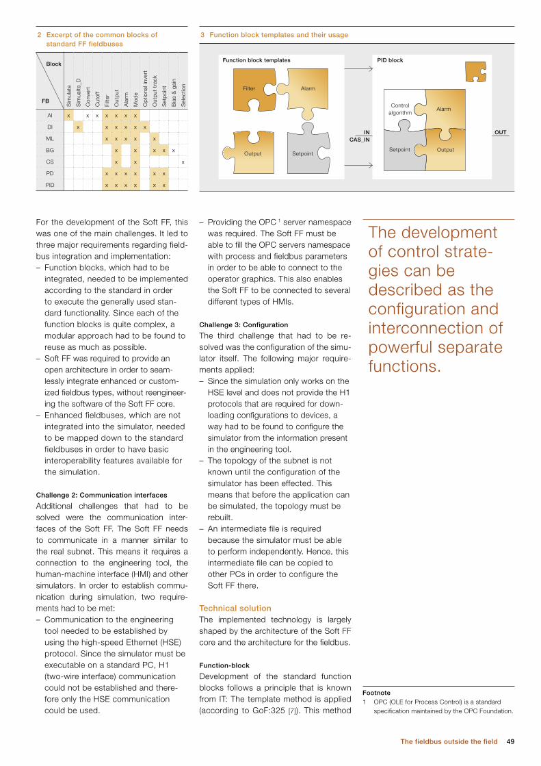
49The fieldbus outside the field
– Providing the OPC 1 server namespace was required. The Soft FF must be able to fill the OPC servers namespace with process and fieldbus parameters in order to be able to connect to the operator graphics. This also enables the Soft FF to be connected to several different types of HMIs.
Challenge 3: Configuration
The third challenge that had to be re-solved was the configuration of the simu-lator itself. The following major require-ments applied:– Since the simulation only works on the
HSE level and does not provide the H1 protocols that are required for down-loading configurations to devices, a way had to be found to configure the simulator from the information present in the engineering tool.
– The topology of the subnet is not known until the configuration of the simulator has been effected. This means that before the application can be simulated, the topology must be rebuilt.
– An intermediate file is required because the simulator must be able to perform independently. Hence, this intermediate file can be copied to other PCs in order to configure the Soft FF there.
Technical solutionThe implemented technology is largely shaped by the architecture of the Soft FF core and the architecture for the fieldbus.
Function-block
Development of the standard function blocks follows a principle that is known from IT: The template method is applied (according to GoF:325 [7]). This method
For the development of the Soft FF, this was one of the main challenges. It led to three major requirements regarding field-bus integration and implementation:– Function blocks, which had to be
integrated, needed to be implemented according to the standard in order to execute the generally used stan-dard functionality. Since each of the function blocks is quite complex, a modular approach had to be found to reuse as much as possible.
– Soft FF was required to provide an open architecture in order to seam-lessly integrate enhanced or custom-ized fieldbus types, without reengineer-ing the software of the Soft FF core.
– Enhanced fieldbuses, which are not integrated into the simulator, needed to be mapped down to the standard fieldbuses in order to have basic interoperability features available for the simulation.
Challenge 2: Communication interfaces
Additional challenges that had to be solved were the communication inter-faces of the Soft FF. The Soft FF needs to communicate in a manner similar to the real subnet. This means it requires a connection to the engineering tool, the human-machine interface (HMI) and other simulators. In order to establish commu-nication during simulation, two require-ments had to be met:– Communication to the engineering
tool needed to be established by using the high-speed Ethernet (HSE) protocol. Since the simulator must be executable on a standard PC, H1 (two-wire interface) communication could not be established and there-fore only the HSE communication could be used.
2 Excerpt of the common blocks of standard FF fieldbuses
3 Function block templates and their usage
The development of control strate-gies can be described as the configuration and interconnection of powerful separate functions.
Sim
ulat
e
Sim
ualte
_D
Con
vert
Cut
off
Filte
r
Out
put
Ala
rm
Mod
e
Op
tiona
l inv
ert
Out
put
tra
ck
Set
poi
nt
Bia
s &
gai
n
Sel
ectio
n
AI x x x x x x x
DI x x x x x x
ML x x x x x
BG x x x x x
CS x x x
PD x x x x x x
PID x x x x x x
FB
Block
Footnote1 OPC (OLE for Process Control) is a standard
specification maintained by the OPC Foundation.
Filter
PID blockFunction block templates
INCAS_IN
OUT
Controlalgorithm
OutputOutput
Alarm
Alarm
SetpointSetpoint
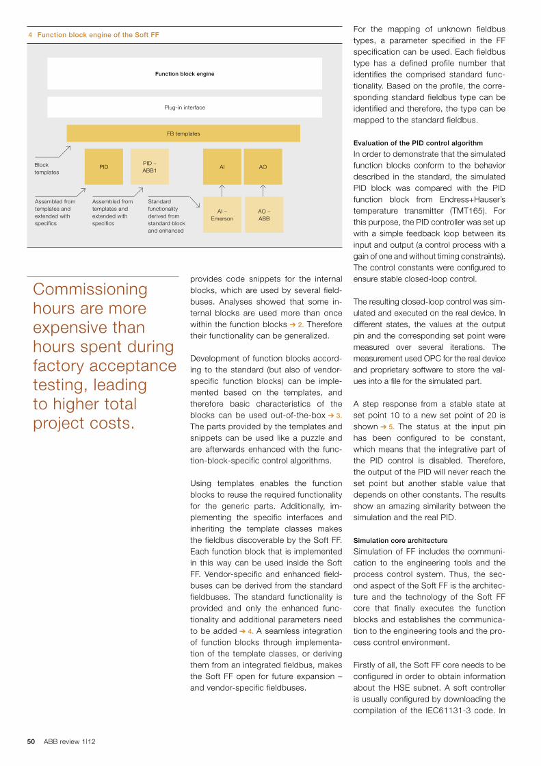
50 ABB review 1|12
For the mapping of unknown fieldbus types, a parameter specified in the FF specification can be used. Each fieldbus type has a defined profile number that identifies the comprised standard func-tionality. Based on the profile, the corre-sponding standard fieldbus type can be identified and therefore, the type can be mapped to the standard fieldbus.
Evaluation of the PID control algorithm
In order to demonstrate that the simulated function blocks conform to the behavior described in the standard, the simulated PID block was compared with the PID function block from Endress+Hauser’s temperature transmitter (TMT165). For this purpose, the PID controller was set up with a simple feedback loop between its input and output (a control process with a gain of one and without timing constraints). The control constants were configured to ensure stable closed-loop control.
The resulting closed-loop control was sim-ulated and executed on the real device. In different states, the values at the output pin and the corresponding set point were measured over several iterations. The measurement used OPC for the real device and proprietary software to store the val-ues into a file for the simulated part. A step response from a stable state at set point 10 to a new set point of 20 is shown ➔ 5. The status at the input pin has been configured to be constant, which means that the integrative part of the PID control is disabled. Therefore, the output of the PID will never reach the set point but another stable value that depends on other constants. The results show an amazing similarity between the simulation and the real PID.
Simulation core architecture
Simulation of FF includes the communi-cation to the engineering tools and the process control system. Thus, the sec-ond aspect of the Soft FF is the architec-ture and the technology of the Soft FF core that finally executes the function blocks and establishes the communica-tion to the engineering tools and the pro-cess control environment.
Firstly of all, the Soft FF core needs to be configured in order to obtain information about the HSE subnet. A soft controller is usually configured by downloading the compilation of the IEC61131-3 code. In
provides code snippets for the internal blocks, which are used by several field-buses. Analyses showed that some in-ternal blocks are used more than once within the function blocks ➔ 2. Therefore their functionality can be generalized.
Development of function blocks accord-ing to the standard (but also of vendor-specific function blocks) can be imple-mented based on the templates, and therefore basic characteristics of the blocks can be used out-of-the-box ➔ 3. The parts provided by the templates and snippets can be used like a puzzle and are afterwards enhanced with the func-tion-block-specific control algorithms.
Using templates enables the function blocks to reuse the required functionality for the generic parts. Additionally, im-plementing the specific interfaces and inheriting the template classes makes the fieldbus discoverable by the Soft FF. Each function block that is implemented in this way can be used inside the Soft FF. Vendor-specific and enhanced field-buses can be derived from the standard fieldbuses. The standard functionality is provided and only the enhanced func-tionality and additional parameters need to be added ➔ 4. A seamless integration of function blocks through implementa-tion of the template classes, or deriving them from an integrated fieldbus, makes the Soft FF open for future expansion – and vendor-specific fieldbuses.
Commissioning hours are more expensive than hours spent during factory acceptance testing, leading to higher total project costs.
4 Function block engine of the Soft FF
FB templates
PID AIPID – ABB1
AI –Emerson
AO –ABB
AO
Function block engine
Plug-in interface
Block templates
Assembled from templates and extended with specifics
Assembled from templates and extended with specifics
Standard functionality derived from standard block and enhanced
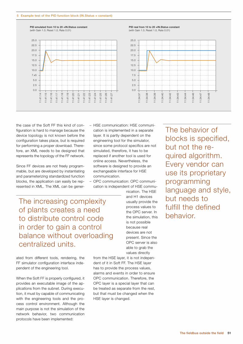
51The fieldbus outside the field
– HSE communication: HSE communi-cation is implemented in a separate layer. It is partly dependent on the engineering tool for the simulator, since some protocol specifics are not simulated, therefore, it has to be replaced if another tool is used for online access. Nevertheless, the software is designed to provide an exchangeable interface for HSE communication.
– OPC communication: OPC communi-cation is independent of HSE commu-
nication. The HSE and H1 devices usually provide the process values to the OPC server. In the simulation, this is not possible because real devices are not present. Since the OPC server is also able to grab the values directly
from the HSE layer, it is not indepen-dent of it in Soft FF. The HSE layer has to provide the process values, alarms and events in order to ensure OPC communication. Therefore, the OPC layer is a special layer that can be treated as separate from the rest, but that must be changed when the HSE layer is changed.
the case of the Soft FF this kind of con-figuration is hard to manage because the device topology is not known before the configuration takes place, but is required for performing a proper download. There- fore, an XML needs to be designed that represents the topology of the FF network.
Since FF devices are not freely program-mable, but are developed by instantiating and parameterizing standardized function blocks, the application can easily be rep-resented in XML. The XML can be gener-
ated from different tools, rendering, the FF simulator configuration interface inde-pendent of the engineering tool.
When the Soft FF is properly configured, it provides an executable image of the ap-plications from the subnet. During execu-tion, it must by capable of communicating with the engineering tools and the pro-cess control environment. Although the main purpose is not the simulation of the network behavior, two communication protocols have been implemented:
The behavior of blocks is specified, but not the re-quired algorithm. Every vendor can use its proprietary programming language and style, but needs to fulfill the defined behavior.
5 Example test of the PID function block (IN.Status = constant)
PID real from 10 to 20 +IN.Status constant(with Gain 1.0, Reset 1.0, Rate 0.01)
25.0
22.5
20.0
17.5
15.0
12.5
10.0
7.5
5.0
2.5
0.0
11:3
4:37
11:3
4:38
11:3
4:39
11:3
4:40
11:3
4:42
11:3
4:43
11:3
4:44
11:3
4:46
11:3
4:47
11:3
4:48
PID emulated from 10 to 20 +IN.Status constant(with Gain 1.0, Reset 1.0, Rate 0.01)
25.0
22.5
20.0
17.5
15.0
12.5
10.0
7.x5
5.0
2.5
0.0
11:4
1:14
11:4
1:15
11:4
1:16
11:4
1:17
11:4
1:18
11:4
1:20
11:4
1:19
11:4
1:21
11:4
1:22
11:4
1:23
11:4
1:24
11:4
1:26
11:4
1:25
11:4
1:27
The increasing complexity of plants creates a need to distribute control code in order to gain a control balance without overloading centralized units.
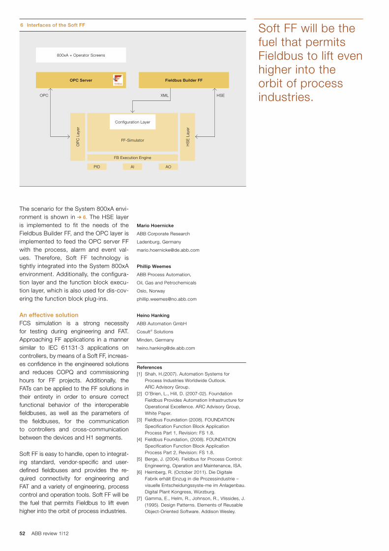
52 ABB review 1|12
Mario Hoernicke
ABB Corporate Research
Ladenburg, Germany
Phillip Weemes
ABB Process Automation,
Oil, Gas and Petrochemicals
Oslo, Norway
Heino Hanking
ABB Automation GmbH
CosultIT Solutions
Minden, Germany
References[1] Shah, H.(2007). Automation Systems for
Process Industries Worldwide Outlook. ARC Advisory Group.
[2] O’Brien, L., Hill, D. (2007-02). Foundation Fieldbus Provides Automation Infrastructure for Operational Excellence. ARC Advisory Group, White Paper.
[3] Fieldbus Foundation (2008). FOUNDATION Specification Function Block Application Process Part 1, Revision: FS 1.8.
[4] Fieldbus Foundation, (2008). FOUNDATION Specification Function Block Application Process Part 2, Revision: FS 1.8.
[5] Berge, J. (2004). Fieldbus for Process Control: Engineering, Operation and Maintenance, ISA.
[6] Heimberg, R. (October 2011). Die Digitale Fabrik erhält Einzug in die Prozessindustrie – visuelle Entscheidungssyste-me im Anlagenbau. Digital Plant Kongress, Würzburg.
[7] Gamma, E., Helm, R., Johnson, R., Vlissides, J. (1995). Design Patterns. Elements of Reusable Object-Oriented Software. Addison Wesley.
The scenario for the System 800xA envi-ronment is shown in ➔ 6. The HSE layer is implemented to fit the needs of the Fieldbus Builder FF, and the OPC layer is implemented to feed the OPC server FF with the process, alarm and event val-ues. Therefore, Soft FF technology is tightly integrated into the System 800xA environment. Additionally, the configura-tion layer and the function block execu-tion layer, which is also used for dis-cov-ering the function block plug-ins.
An effective solutionFCS simulation is a strong necessity for testing during engineering and FAT. Approaching FF applications in a manner similar to IEC 61131-3 applications on controllers, by means of a Soft FF, increas-es confidence in the engineered solutions and reduces COPQ and commissioning hours for FF projects. Additionally, the FATs can be applied to the FF solutions in their entirety in order to ensure correct functional behavior of the inter operable fieldbuses, as well as the para meters of the fieldbuses, for the communication to controllers and cross-communication between the devices and H1 segments.
Soft FF is easy to handle, open to integrat-ing standard, vendor-specific and user-defined fieldbuses and provides the re-quired connectivity for engineering and FAT and a variety of engineering, process control and operation tools. Soft FF will be the fuel that permits Fieldbus to lift even higher into the orbit of process industries.
Soft FF will be the fuel that permits Fieldbus to lift even higher into the orbit of process industries.
6 Interfaces of the Soft FF
800xA + Operator Screens
OPC Server
FF-Simulator
Fieldbus Builder FF
Configuration Layer
FB Execution Engine
PID AI AO
OP
C L
ayer
HS
E L
ayer
HSEOPC XML

53Winning by design
Innovative door communication system wins international design award
JüRGEN HöGENER – Products from the ABB Group often attract attention because of their technical attributes, and the Busch-Jaeger door communication system is no exception (Busch-Jaeger is a member of the ABB Group). But this product has gone one better by winning the iF product design award 2012. Not only that, but Busch-Jaeger was also
awarded the label “Interior Innovation Award – Winner 2012” in the run-up to the international furnishing trade fair “imm cologne” for four of its products: Busch-Welcome® audio outdoor station, Busch-Welcome® video outdoor station, Busch-Welcome® indoor audio station with display and Busch-WelcomePanel®.
Winning by design
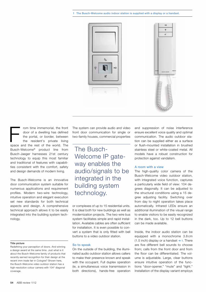
54 ABB review 1|12
and suppression of noise interference ensure excellent voice quality and optimal communication. The audio outdoor sta-tion can be supplied either as a surface or flush-mounted installation in brushed stainless steel or white-coated metal. All models have a robust construction for protection against vandalism.
A room with a viewThe high-quality color camera of the Busch-Welcome video outdoor station, with integrated voice function, captures a particularly wide field of view: 104 de-grees diagonally. It can be adjusted to the structural conditions using a 15 de-gree adjusting facility. Switching over from day to night operation takes place automatically. Infrared LEDs ensure an additional illumination of the visual range to enable visitors to be easily recognized in the dark, too. Up to 12 bell buttons can be made available.
Inside, the indoor audio station can be equipped with a monochrome 3.8 cm (1.5 inch) display or a handset ➔ 1. There are five different bell sounds to choose from; calls from the front door and from the floor can be differentiated. The vol-ume is adjustable. Large, clear buttons ensure intuitive operation of the func-tions “door-opener,” “mute” and “light.” Installation of the display variant employs
The system can provide audio and video front door communication for single or two-family houses, commercial properties
or complexes of up to 15 residential units. It is ideal both for new buildings as well as modernization projects. The two-wire bus system facilitates simple and rapid instal-lation. Available cables are often sufficient for installation. It is even possible to con-vert a system that is only fitted with bell buttons to a video outdoor station.
So to speakOn the outside of the building, the illumi-nated audio outdoor station allows callers to make their presence known and speak with the occupant. Full duplex operation (ie, a simultaneous voice transmission in both directions), hands-free operation
F rom time immemorial, the front door of a dwelling has defined the portal, or border, between the resident's private living
space and the rest of the world. The Busch-Welcome® product line from Busch-Jaeger harnesses 21st century technology to equip this most familiar and traditional of features with capabili-ties consistent with the comfort, safety and design demands of modern living.
The Busch-Welcome is an innovative door communication system suitable for numerous applications and requirement profiles. Modern two-wire technology, intuitive operation and elegant execution set new standards for both technical aspects and design. A comprehensive technical approach allows it to be easily integrated into the building system tech-nology.
Title pictureRedefining your perception of doors. And winning a design award at the same time. Just what is it about the Busch-Welcome family of products that recently earned recognition for their design at the recent imm trade fair in Cologne? Shown here, the Busch-Welcome video outdoor station has a high-resolution colour camera with 104° diagonal coverage.
1 The Busch-Welcome audio indoor station is supplied with a display or a handset.
The Busch- Welcome IP gate-way enables the audio/signals to be integrated in the building system technology.
55Winning by design
the design world: The Busch-Welcome was awarded the prestigious “iF product design award 2012” by the “iF interna-tional forum design.” Busch-Jaeger was also awarded the label “Interior Innova-tion Award – Winner 2012” for four of its products in the run-up to the imm co-logne 2012 trade fair, where the awarded products were presented in a special exhibition.
The design of the Busch-Welcome sys-tem is indeed noteworthy, not only for its intuitive operation but also because of the first-class materials used and the excellent surface qualities of the finish. With its surface or flush-mounted instal-lation and unobtrusive aesthetics it blends in harmoniously both outdoors and indoors with any architectural con-cept. For indoors, the products are aligned, in both form and material, to combine perfectly with Busch-Jaeger light switches and sockets. This holistic approach and uniformity of design en-sure consistent optics in every room.
It is these qualities, and more, that attracted the favorable attention of the judges of two of the most famous inter-national design awards in Germany.
Jürgen Högener
Busch-Jaeger Elektro GmbH,
a member of the ABB Group
Luedenscheid, Germany
the audio/video indoor/outdoor stations, the electric door opener and the hall light.
By means of the Busch-Welcome video outdoor distributor, several video out-door stations can be connected to the central system. This is useful, for exam-ple, if a building has several entrances. In turn, the Busch-Welcome video indoor distributor offers the possibility of trans-mitting the video signal from the entrance door to the rest of the building. In this way, the display image can be received in different dwellings or in several rooms. The video indoor distributor can be sup-plied as a flush-mounted installation or modular device (REG).
The Busch-Welcome IP gateway for the Busch-ComfortPanel® enables the audio and video signals of the Busch-Welcome system to be integrated into the building system technology. By means of the IP gateway, the Busch-ComfortPanel be-comes a convenient video indoor inter-com system. The IP gateway connects the two-wire bus system of the Busch-Welcome system on the one side with the Ethernet IP network on the other.
Design inspirationThe new door communication system from Busch-Jaeger has also inspired
two flush-mounted boxes rather than the one surface-mounted box used for the handset variant.
Better looking The video capabilities of the system are taken up a level with the product known as the Busch-WelcomePanel®. With this, visitors are clearly shown with high reso-lution and strongly contrasting colors on a large 17.8 cm (7 inch) TFT touch-pan-el ➔ 2. Six fast-access buttons and self-explanatory, touch-panel operations fa-cilitate intuitive control of all the functions. During voice communication with the visitor outside the door, photos can be taken and stored. During an absence, three photos of each visitor are taken auto matically after the bell has been rung. The Busch-WelcomePanel is easy to install on the wall.
When it is not being used for entry moni-toring, the Busch-WelcomePanel also functions as a digital picture frame to show favorite photos. A standard SD-card is all that is required for showing the picture files on the display.
Busch-Welcome® system componentsThe central Busch-Welcome system, constructed in the form of a modular device, supplies and controls the constituent components, ie, it connects
2 The Busch-WelcomePanel is fitted with a high-quality 17.8 cm (7 inch) TFT touch-screen.
56 ABB review 1|12
CHRISTOPHER WATTS – Industrial production is set to continue expanding in the coming decades. Yet, at the same time, growing concern about climate change is leading to pressure on industrial companies to minimize their environmental impact. The results of a recent survey of industrial executives, commissioned by ABB and researched and written by the Economist Intelligence Unit, identified the critical importance of energy efficiency to long-term profitability and identified
several barriers to investments in energy efficient technolo-gies by industry. Despite the barriers, most executives partici-pating in the survey indicated that they expect to increase investments in energy efficiency in the coming years; how-ever, this will not result from the adoption of voluntary energy efficiency programs, but rather from the implementation of new regulations, that will put increased pressure on their companies to improve energy efficiency.
Regulatory issues set the agenda (part 3)
The frugal manufacturer
57The frugal manufacturer
Regulation is already beginning to emerge as a major theme driving investment in improvement of industrial energy efficiency.
efficiency. For now, it does not appear that industry managers consider energy regulation to be a heavy burden. Asked how they would describe industrial en-ergy efficiency regulation in their home countries, 50 percent say “modest, not onerous,” compared with 40 percent who say it is “somewhat stringent” or “very stringent.” Power firms are more likely (45 percent) to consider regulation stringent than manufacturers (39 per-cent). And while more respondents in developed economies (45 percent, with Western Europe as high as 53 per- cent) are likely to take this view than in developing markets (32 percent), one exception is North America, where just 31 percent consider regulation to be stringent ➔ 6.
that some other energy-intensive manu-facturers are now taking steps to miti-gate a return to the peak energy prices seen in 2008, as economic conditions gradually stabilize and restrictions on capital expenditure begin to ease.
While, on the whole, growth in invest-ment in energy efficiency remained mod-est in the past year, executives appear confident that their companies will in-crease spending on improvements in ef-ficiency in the next three years. Seventy-three percent of all respondents expect their company to spend more in the coming three years. Of these, about 13 percent expect a very significant in-crease. In Western Europe, a slightly higher proportion (16 percent) than aver-age expects a very significant increase, perhaps in anticipation of intensifying regulatory pressure in the European Union ➔ 5.
Indeed, regulation is already beginning to emerge as a major theme driving invest-ment in improvement of industrial energy
I n the third and final part of “The frugal manufacturer” series ➔ 1–3, we look at what will drive industry to invest in energy efficiency measures. While the
majority (58 percent) of surveyed execu-tives indicate they increased their invest-ments in energy efficiency in the past year, versus the prior year, a very signifi-cant proportion (42 percent) say their in-vestments were static or fell in the past year. Even among those that did increase their investments, almost half (48 per-cent) did so by 10 percent or less ➔ 4.
On a positive note, manufacturers in high energy-intensity industries are more like-ly (15 percent) to have increased invest-ment very significantly (defined as 30 percent or more year-on-year) than lower energy-intensity manufacturers (10 per-cent) or power producers (5 percent). Apollo Tyres is one example: The com-pany says its investments in energy effi-ciency have grown 50 percent year-on-year (from a low base), due to new waste heat recovery equipment at its plant in Vadodara in western India. It’s possible
Title pictureABB supplied motors, drives, transformers, switchgear and more to improve energy efficiency at the Aitik copper mine in Sweden, which finalized the modernization of its entire operation in 2010, enabling mine operator Boliden to double its production capacity and extend the life of the mine.
58 ABB review 1|12
“But it requires us to do the audit, and it requires us to give sight to directors of the [efficiency improvement] oppor-tunities. I actually think that’s reason-ably helpful.”
As policy makers across the globe ad-dress climate change issues, voluntary industrial energy efficiency frameworks, such as those in the United States and Australia, are increasingly being joined by mandatory regulations. In the United States in 2010, for example, new regula-tions came into force under the Energy Independence and Security Act, which
stipulate the mini-mum energy effi-ciency of new in-dustrial motors sold in the United States. Canada, Mexico, and Brazil have intro duced similar requirements; and in mid-2011 the European Union
adopted related regulation in three stages. Meanwhile, in April 2011, India launched the Perform, Achieve and Trade
A light regulatory frameworkUntil recently, few businesses have been subject to mandatory energy effi-ciency requirements. More widespread are opt-in schemes, such as the Energy Star program in the United States, or the Energy Efficiency Opportunities (EEO) program in Australia, which pro-vide a basis for companies to improve their industrial energy efficiency. The EEO, for example, calls on participating companies to identify, assess and re-port on potential energy savings im-provements. “It doesn’t mandate we actually do any of them,” says Ian Gilm-
our, safety, health and environment and manufacturing manager at Orica, an Australian chemicals manufacturer.
This series of articles published in ABB Review presents the findings of a report commissioned by ABB and researched and written by the Economist Intelligence Unit.
The survey collected input from 348 senior industry executives, mostly in North America, Asia-Pacific, and Western Europe, asking them about their plans to invest in improving energy efficiency in production processes, the issues they face as they consider these investments, and the factors that are likely to influence industrial energy efficiency in the coming years.
In addition to the online survey, the study conducted 15 in-depth interviews with senior business executives, policy makers, and other experts in industrial energy efficiency.
The first part of the ABB Review series, “The frugal manufacturer: Using energy sparingly," was published in ABB Review 3/2011 (pages 7 to 12). The findings include:– Eighty-eight percent of respondents say
industrial energy efficiency will be a critical success factor for their business in the coming two decades.
– Seventy-two percent “agree strongly” or “agree somewhat” that energy efficiency is a critical success factor for manufacturers today.
– Fifty-nine percent say that in making the financial and business case for invest-ments in efficiency, the energy price is one of the biggest factors.
– Twenty-six percent see improving their company’s image as another reason to invest in energy efficiency.
6 ABB review 3|11 7The frugal manufacturer
More than two-thirds of respondents to the survey are executives at director lev-el. Respondents are most likely to have responsibility for strategy and business development, finance, general manage-ment, and operations and production. Around 58 percent are from businesses with $500 million or more in global an-nual revenues. The survey focuses en-tirely on the manufacturing and power sectors, with manufacturing having the strongest representation.
I n January-February 2011, the Econ-omist Intelligence Unit surveyed 348 senior executives, mostly in North America, Asia-Pacific, and Western
Europe, on their plans to invest in im-proving energy efficiency in production processes, the issues they face as they consider these investments, and the fac-tors that are likely to influence industrial energy efficiency in the coming years. This is the first of three articles to appear in ABB Review based on the results of that survey, as well as on a program of in-depth interviews and desk research on the topic of industrial energy efficien-cy. In addition, the study is based on a separate comprehensive analysis of the worldwide energy consumption patterns of seven energy-intensive industries, carried out by the energy information and consulting firm, Enerdata.
ChrisTopher WaTTs – as the world leaves a long era of energy abundance and enters an era of constraint, many complex challenges face government, business and society. among these is resolving the conflict between raising living stan-dards in developing regions by continuing to expand industrial production, and lessening the negative environmental impacts of industrial manufacturing activi-ties across the world. one of the approaches to addressing this challenge is to improve energy efficiency in the core of industry’s production processes.
Part 1, Using energy sparingly
The frugal manufacturer
Title picture The Palmachim water desalination/purification plant. The desalination process is energy intensive. ABB has supplied energy-efficient drives for this installation. ABB’s contribution to water supplies will be discussed at length in ABB Review 4/2011.
2 Summary of part 1: industry leaders recog - nize the importance of energy efficiency
The second part of the ABB Review series, “The frugal manufacturer: Analyzing industry’s commitment to improvement,” was published in ABB Review 4/2011 (pages 55 to 59). The findings include:– Only 40 percent of survey respondents
say they have invested in capital, plant and equipment to improve energy efficiency within the past three years.
– Forty-six percent of firms do not have a company-wide energy management system in place to track and optimize energy use.
– Just 34 percent of companies have conducted an energy audit across the entire company or group.
– Seventy-seven percent of survey respondents agree that “industries need clearer benchmarks for what constitutes energy efficiency” in their sectors.
55 54 ABB review 4|11 The frugal manufacturer
I n issue 3/2011 of ABB Review, the first part of this series of articles dis-cussed the importance of energy efficiency to industry ➔ 2. The find-
ings were based on a survey commis-sioned by ABB and performed by the Economist Intelligence Unit ➔ 1. While most industry managers appear to ap-preciate the importance of energy effi-ciency in securing long-term financial performance, relatively few are practicing the discipline, and low levels of energy-efficiency remain the norm. Only 40 per-cent of survey respondents say they have invested in capital, plant and equipment to im-prove energy effi-ciency within the past three years. Respondents who have done so are more likely to be in developing econo-mies, where 49 percent have invested in equipment to improve energy efficiency, versus 34 per-cent in developed regions. North Ameri-ca trails clearly in this respect, with only 21 percent of respondents saying their firms have invested in equipment over the past three years to improve energy efficiency.
Looking beyond investments in plant and equipment, and focusing on energy effi-ciency practices, the situation remains poor – but slightly less so. 46 percent of firms do not have a company-wide energy management system in place to track and optimize energy use, accord-ing to survey results; 50 percent do have such systems; the rest say they don’t know. Among relatively small firms in the survey sample (annual revenues under $ 1 billion), a clear majority, 55 percent, have no energy management system. These findings are all the more surprising
given that experts consider various kinds of energy management systems to be highly cost-effective ➔ 3.
At one level, an energy management system may refer to an organizational framework to actively take control of cor-porate energy use – as, for example, the new ISO 50001 standard, due in the sec-
ChrisTopher WaTTs – energy, so our physics books tell us, is the ability to do work, and work is at the heart of all industrial production. in view of the environmental impacts of its energy footprint and the rising price of energy, industry is having to re-assess its energy usage and seek to produce more with less. part two of this three-part article investigates why commit-ment to energy efficiency in industry remains weak despite the broad acknowledgement of its value.
Part 2, Analyzing industry’s commitment to improvement
The frugal manufacturer
Title pictureThe importance of measures to increase energy efficiency is broadly recognized in industry. In many sectors, however, the implementation is lagging behind. The title illustration shows the mechanical hoist drum at Totten mine, Sudbury, Ontario, Canada, which is equipped with energy-efficient drives from ABB.
Forty-six percent of firms do not have a company- wide energy management system in place to track and optimize energy use.
3 Summary of part 2: analyzing industry’s commitment to improvement
Executives appear confident that their companies will increase spending on improvements in efficiency in the next three years.
1 The frugal manufacturer
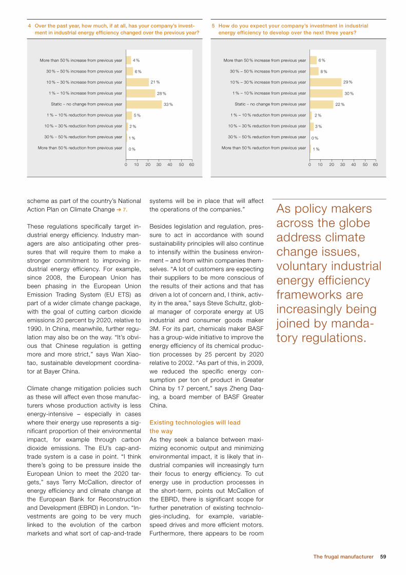
59The frugal manufacturer
systems will be in place that will affect the operations of the companies.”
Besides legislation and regulation, pres-sure to act in accordance with sound sustainability principles will also continue to intensify within the business environ-ment – and from within companies them-selves. “A lot of customers are expecting their suppliers to be more conscious of the results of their actions and that has driven a lot of concern and, I think, activ-ity in the area,” says Steve Schultz, glob-al manager of corporate energy at US industrial and consumer goods maker 3M. For its part, chemicals maker BASF has a group-wide initiative to improve the energy efficiency of its chemical produc-tion processes by 25 percent by 2020 relative to 2002. “As part of this, in 2009, we reduced the specific energy con-sumption per ton of product in Greater China by 17 percent,” says Zheng Daq-ing, a board member of BASF Greater China.
Existing technologies will lead the wayAs they seek a balance between maxi-mizing economic output and minimizing environmental impact, it is likely that in-dustrial companies will increasingly turn their focus to energy efficiency. To cut energy use in production processes in the short-term, points out McCallion of the EBRD, there is significant scope for further penetration of existing technolo-gies-including, for example, variable-speed drives and more efficient motors. Furthermore, there appears to be room
scheme as part of the country’s National Action Plan on Climate Change ➔ 7.
These regulations specifically target in-dustrial energy efficiency. Industry man-agers are also anticipating other pres-sures that will require them to make a stronger commitment to improving in-dustrial energy efficiency. For example, since 2008, the European Union has been phasing in the European Union Emission Trading System (EU ETS) as part of a wider climate change package, with the goal of cutting carbon dioxide emissions 20 percent by 2020, relative to 1990. In China, meanwhile, further regu-lation may also be on the way. “It’s obvi-ous that Chinese regulation is getting more and more strict,” says Wan Xiao-tao, sustainable development coordina-tor at Bayer China.
Climate change mitigation policies such as these will affect even those manufac-turers whose production activity is less energy-intensive – especially in cases where their energy use represents a sig-nificant proportion of their environmental impact, for example through carbon dioxide emissions. The EU’s cap-and-trade system is a case in point. “I think there’s going to be pressure inside the European Union to meet the 2020 tar-gets,” says Terry McCallion, director of energy efficiency and climate change at the European Bank for Reconstruction and Development (EBRD) in London. “In-vestments are going to be very much linked to the evolution of the carbon markets and what sort of cap-and-trade
4 Over the past year, how much, if at all, has your company’s invest-ment in industrial energy efficiency changed over the previous year?
4 %
6 %
21 %
28 %
33 %
5 %
2 %
1 %
0 %
0 10 20 30 40 50 60
More than 50 % increase from previous year
30 % – 50 % increase from previous year
10 % – 30 % increase from previous year
1 % – 10 % increase from previous year
Static – no change from previous year
1 % – 10 % reduction from previous year
10 % – 30 % reduction from previous year
30 % – 50 % reduction from previous year
More than 50 % reduction from previous year
5 How do you expect your company’s investment in industrial energy efficiency to develop over the next three years?
6 %
8 %
29 %
30 %
22 %
0 %
1 %
0 10 20 30 40 50 60
More than 50 % increase from previous year
30 % – 50 % increase from previous year
10 % – 30 % increase from previous year
1 % – 10 % increase from previous year
Static – no change from previous year
1 % – 10 % reduction from previous year
10 % – 30 % reduction from previous year
30 % – 50 % reduction from previous year
More than 50 % reduction from previous year
3 %
2 %
As policy makers across the globe address climate change issues, voluntary industrial energy efficiency frameworks are increasingly being joined by manda-tory regulations.

60 ABB review 1|12
For this to happen, of course, research and development, innovation, and col-laboration have a central role to play, a point that is highlighted by L. Rajasekar, executive president of UltraTech Ce-ment, an Indian cement producer. He says the company typically allocates 0.2 to 0.3 percent of annual revenues to its corporate research and development ef-forts, and in addition, funds common re-search programs run by the European Cement Research Academy based in Düsseldorf, Germany. “We need to have more and more collaborative work on re-search, because some of these things are not possible in individual compa-nies,” Rajasekar says. “Ultimately, the results have to be for [the benefit of] the whole industry.”
Not surprisingly, as industry grapples with the compliance issues around ener-gy efficiency and environmental legisla-tion, the question emerges: Who will pay? Some industrial companies are calling on policy makers to improve tax incentives and subsidy schemes for en-ergy efficiency improvement measures.
for better management of energy use. In other words, significant improvements in industrial energy efficiency appear to be within relatively easy reach of many industry executives today.
For a few executives, however, this is not the case. Wan Xiaotao at Bayer China is one. “If we look at Bayer Mate-rialScience in China, the plants and equipment are pretty much new,” he says. “They’ve all been built within the last five to six years, so there is little opportunity to upgrade the equipment to improve efficiency.” In cases such as these, and many more besides, further advances in production processes will enable industry to improve efficien-cy ➔ 8. Ajay Mathur, director general of the Bureau of Energy Efficiency (BEE), a Government of India body, predicts, “We will probably start seeing changes in manufacturing processes occurring towards the end of this decade.”
Since 2008, the European Union has been phasing in the European Union Emission Trading System as part of a wider climate change package, with the goal of cutting car-bon dioxide emis-sions 20 percent by 2020, relative to 1990.
To add momentum to improvements in energy efficiency in India’s heavy industry, the Govern - ment of India recently introduced a mandatory energy efficiency scheme for the country’s largest industrial sites. The so-called Perform, Achieve and Trade (PAT) scheme, the country’s first set of mandatory industrial energy regulations, came into force on April 1, 2011.
PAT is a market-based mechanism, similar to carbon dioxide emissions trading mechanisms seen elsewhere. Under the PAT scheme, over 600 individual industrial units in eight sectors across India, including plants that produce cement, power, chemicals, pulp and paper, iron and steel, and aluminum, are given targets to improve their energy efficiency. In all, these units account for around half of India’s industrial energy demand.
The PAT scheme requires each plant to cut its specific energy consumption by a fixed percentage over a three-year timeframe, based on its current energy use. There is no industry-wide benchmark, nor is the required percentage reduction negotiable. Under the PAT scheme, plant owners are required to appoint an energy manager, provide authorities with an energy consumption report, comply with energy efficiency norms, and allow designated energy auditors to verify compli-ance. Failure to comply results in a hefty fine.
Each industrial site is allocated a quota of energy-saving certificates (ESCerts); sites that exceed their energy-savings targets are given extra certificates. The certificates can be traded at market-driven prices via the Indian Energy Exchange. Those failing to meet efficiency improvement targets can comply with the PAT scheme by buying extra ESCerts. Government officials say that the scheme is designed to accommodate the ongoing strong industrial growth in India, the wide bandwidth of specific energy consumption across individual sectors, and the need for transparent procedures that cannot be manipulated or negotiated. Over a 10-year period the government expects a 10 to 15 percent improvement in energy efficiency, largely driven by upgrades in technology.
L. Rajasekar, executive president of Indian cement manufacturer UltraTech Cement, points out how the new PAT scheme adds weight to the financial case for investment in improving energy efficiency. “If you take into consideration the penalties [for noncompli-ance], then your payback period comes down, practically by half,” he says. “If you have a six-year payback, it becomes three years. In a way, it will help us.”
7 India’s policy makers increase the pressure on industry
15 %
25 %
50 %
8 %
1 %
0 10 20 30 40 50 60
Very stringent
Somewhat stringent
Modest, not onerous
Non-existent
Don’t know
*In the country in which you are based
6 How would you describe legislation and regula - tion governing industrial energy efficiency?*
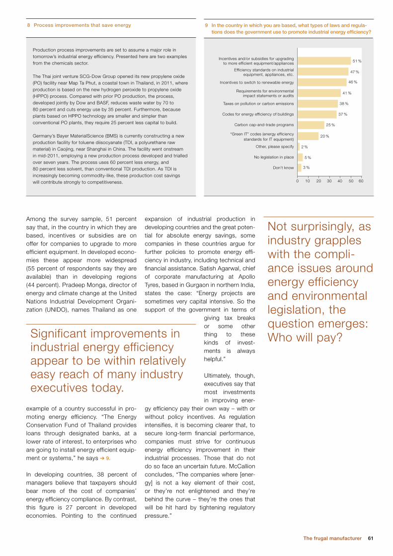
61The frugal manufacturer
expansion of industrial production in devel oping countries and the great poten-tial for absolute energy savings, some companies in these countries argue for further policies to promote energy effi-ciency in industry, including technical and financial assistance. Satish Agarwal, chief of corporate manufacturing at Apollo Tyres, based in Gurgaon in northern India, states the case: “Energy projects are sometimes very capital inten sive. So the support of the government in terms of
giving tax breaks or some other thing to these kinds of invest-ments is always helpful.”
Ultimately, though, executives say that most investments in improving ener-
gy efficiency pay their own way – with or without policy incentives. As regulation intensifies, it is becoming clearer that, to secure long-term financial performance, companies must strive for continuous energy efficiency improvement in their industrial processes. Those that do not do so face an uncertain future. McCallion concludes, “The companies where [ener-gy] is not a key element of their cost, or they’re not enlightened and they’re behind the curve – they’re the ones that will be hit hard by tightening regulatory pressure.”
Among the survey sample, 51 percent say that, in the country in which they are based, incentives or subsidies are on offer for companies to upgrade to more efficient equipment. In developed econo-mies these appear more widespread (55 percent of respondents say they are available) than in developing regions (44 percent). Pradeep Monga, director of energy and climate change at the United Nations Industrial Development Organi-zation (UNIDO), names Thailand as one
example of a country successful in pro-moting energy efficiency. “The Energy Conservation Fund of Thailand provides loans through designated banks, at a lower rate of interest, to enterprises who are going to install energy efficient equip-ment or systems,” he says ➔ 9.
In developing countries, 38 percent of managers believe that taxpayers should bear more of the cost of companies’ energy efficiency compliance. By contrast, this figure is 27 percent in developed economies. Pointing to the con tinued
Not surprisingly, as industry grapples with the compli-ance issues around energy efficiency and environmental legislation, the question emerges: Who will pay?
Production process improvements are set to assume a major role in tomorrow’s industrial energy efficiency. Presented here are two examples from the chemicals sector.
The Thai joint venture SCG-Dow Group opened its new propylene oxide (PO) facility near Map Ta Phut, a coastal town in Thailand, in 2011, where production is based on the new hydrogen peroxide to propylene oxide (HPPO) process. Compared with prior PO production, the process, developed jointly by Dow and BASF, reduces waste water by 70 to 80 percent and cuts energy use by 35 percent. Furthermore, because plants based on HPPO technology are smaller and simpler than conventional PO plants, they require 25 percent less capital to build.
Germany’s Bayer MaterialScience (BMS) is currently constructing a new production facility for toluene diisocyanate (TDI, a polyurethane raw material) in Caojing, near Shanghai in China. The facility went onstream in mid-2011, employing a new production process developed and trialled over seven years. The process uses 60 percent less energy, and 80 percent less solvent, than conventional TDI production. As TDI is increasingly becoming commodity-like, these production cost savings will contribute strongly to competitiveness.
8 Process improvements that save energy
51 %
47 %
46 %
41 %
38 %
25 %
37 %
20 %
2 %
5 %
3 %
0 10 20 30 40 50 60
Incentives and/or subsidies for upgradingto more efficient equipment/appliances
Efficiency standards on industrialequipment, appliances, etc.
Incentives to switch to renewable energy
Requirements for environmentalimpact statements or audits
Taxes on pollution or carbon emissions
Codes for energy efficiency of buildings
Carbon cap-and-trade programs
“Green IT” codes (energy efficiencystandards for IT equipment)
Other, please specify
No legislation in place
Don’t know
9 In the country in which you are based, what types of laws and regula-tions does the government use to promote industrial energy efficiency?
Significant improvements in industrial energy efficiency appear to be within relatively easy reach of many industry executives today.
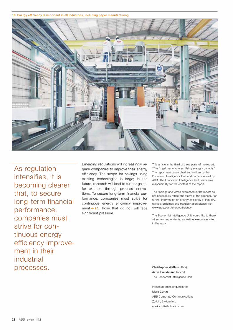
62 ABB review 1|12
This article is the third of three parts of the report, “The frugal manufacturer: Using energy sparingly.” The report was researched and written by the Economist Intelligence Unit and commissioned by ABB. The Economist Intelligence Unit bears sole responsibility for the content of the report.
The findings and views expressed in the report do not necessarily reflect the views of the sponsor. For further information on energy efficiency of industry, utilities, buildings and transportation please visit www.abb.com/energyefficiency
The Economist Intelligence Unit would like to thank all survey respondents, as well as executives cited in the report.
Christopher Watts (author)
Aviva Freudmann (editor)
The Economist Intelligence Unit
Please address enquiries to:
Mark Curtis
ABB Corporate Communications
Zurich, Switzerland
Emerging regulations will increasingly re-quire companies to improve their energy efficiency. The scope for savings using existing technologies is large; in the future, research will lead to further gains, for example through process innova-tions. To secure long-term financial per-formance, companies must strive for continuous energy efficiency improve-ment ➔ 10. Those that do not will face significant pressure.
As regulation intensifies, it is becoming clearer that, to secure long-term financial performance, companies must strive for con-tinuous energy efficiency improve-ment in their industrial processes.
10 Energy efficiency is important in all industries, including paper manufacturing
63Preview
As a provider of products, services and solutions to a broad range of industries, utilities and end consumers, ABB is helping shape many aspects of the world of tomorrow. Issue 2/2012 of ABB Review will present some of ABB’s technologies and their implications.
With online activities taking a more and more pivotal role in today’s lifestyle, the data centers that handle this ever-increasing flow of information are also growing in importance – and with them their power consumption. Bringing in its vast automation and power experience, ABB is revolutionizing these power supplies and raising their energy efficiency and reliability. Continu-ing with the online theme, we will look at remote service and how data can be shared remotely with the service provider without compromising the integrity of the customer or their equipment.
Moving on to a different aspect of service, issue 2/2012 will address how ABB can pinpoint faults in underground cables; how ABB is improving the ecological footprint of transformer manufacturing; what DC networks can do for ships; efficient motors for irrigation; and an energy control center for the home.
Focus on technology
Preview 2|12
Editorial Board
Claes RytoftChief Technology OfficerGroup R&D and Technology
Clarissa HallerHead of Corporate Communications
Ron PopperHead of Corporate Responsibility
Eero JaaskelaHead of Group Account Management
Andreas MoglestueChief Editor, ABB Review
PublisherABB Review is published by ABB Group R&D and Technology.
ABB Technology Ltd.ABB ReviewAffolternstrasse 44 CH-8050 [email protected]
ABB Review is published four times a year in English, French, German, Spanish, Chinese and Russian. ABB Review is free of charge to those with an interest in ABB’s technology and objectives. For a sub scription, please contact your nearest ABB representative or subscribe online at www.abb.com/abbreview
Partial reprints or reproductions are per mitted subject to full acknowledgement. Complete reprints require the publisher’s written consent.
Publisher and copyright ©2012ABB Technology Ltd. Zurich/Switzerland
PrinterVorarlberger Verlagsanstalt GmbHAT-6850 Dornbirn/Austria
LayoutDAVILLA AGZurich/Switzerland
DisclaimerThe information contained herein reflects the views of the authors and is for informational purposes only. Readers should not act upon the information contained herein without seeking professional advice. We make publications available with the understanding that the authors are not rendering technical or other professional advice or opinions on specific facts or matters and assume no liability whatsoever in connection with their use. The companies of the ABB Group do not make any warranty or guarantee, or promise, expressed or implied, concerning the content or accuracy of the views expressed herein.
ISSN: 1013-3119
www.abb.com/abbreview
Connect renewable power to the grid?
Naturally.
Electricity generated by water, sun and wind is most abundant in remote areas like mountains, deserts or far out at sea. ABB’s leading power and automation technologies help renewable power reach about 70 million people by integrating it into electrical grids, sometimes over vast distances. Our effort to harness renewable energy is making power networks smarter, and helping to protect the environment and fight climate change. www.abb.com/betterworld


![[11] ABB Review 3_2008](https://img.pdfslide.us/doc/110x75/5527a726550346c3358b4854/11-abb-review-32008.jpg)