Embed Size (px)
Citation preview
DOC. N° 1SDH002003A1002 ECN000141620 Rev. C
ABB Ekip UP
Switchgear digital unit for monitoring, protecting and controlling plant
Manual on use, installation, configuration and maintenancefor the installing technician and user

1SDH002003A1002 ECN000141620 Rev. C Ekip UP | 2
Contents
Index of contentsCONTENTS ............................................................... 2Index of contents ................................................................ 2Index of figures ................................................................... 3Index of tables .................................................................... 4
GLOSSARY AND DEFINITIONS ............................... 7INTRODUCTION ....................................................... 81 - Contents .................................................................... 82 - Safety ........................................................................ 9
GENERAL VIEW OF EKIP UP ................................. 103 - Main features ........................................................... 104 - Operating conditions................................................. 14
STARTUP AND MANAGEMENT OPERATIONS ..... 175 - Receipt .................................................................... 186 - Installation................................................................ 207 - Commissioning......................................................... 218 - Maintenance and fault identification .......................... 239 - Decommissioning ..................................................... 28
INTERFACE AND MENUS ...................................... 2910 - Interface presentation ............................................... 2911 - Navigation ................................................................ 3112 - Graphic pages .......................................................... 3313 - Menu ....................................................................... 3714 - Modifying parameters and commands ....................... 4315 - Password and security.............................................. 45
MEASUREMENTS................................................... 4616 - Standard measurements .......................................... 4617 - Datalogger ............................................................... 5018 - Network Analyzer ..................................................... 5219 - TRIPS ...................................................................... 60
PROTECTIONS ....................................................... 6120 - Current protections ................................................... 6321 - Voltage protections ................................................... 8222 - Power protections..................................................... 8723 - Frequency protections .............................................. 9224 - Other protections ...................................................... 9625 - Logic Selectivity ....................................................... 9926 - Performance tables ................................................ 10127 - Curves ................................................................... 103
CONTROL ............................................................. 11728 - Power Controller ..................................................... 117
SETTINGS ............................................................. 12029 - Main settings .......................................................... 12030 - Supplementary settings .......................................... 123
TEST ..................................................................... 12531 - Test ....................................................................... 125
ADDITIONAL FUNCTIONS ................................... 12732 - Load Shedding ....................................................... 127
STANDARD MODULES ........................................ 12933 - Current Sensors ..................................................... 12934 - Rating plug ............................................................. 13335 - Ekip Supply ............................................................ 13436 - Ekip Measuring....................................................... 13537 - Ekip Signalling 4K................................................... 137
ACCESSORIES ..................................................... 14038 - Ekip Com Modbus RTU .......................................... 14039 - Ekip Com Profibus DP ............................................ 14340 - Ekip Com DeviceNetTM ........................................... 14641 - Ekip Com TCP Modbus .......................................... 14942 - Ekip Com Profinet................................................... 15343 - Ekip Com EtherNet/IPTM ......................................... 15644 - Ekip Com IEC 61850 .............................................. 16045 - Ekip Link ................................................................ 16546 - Ekip Com Hub ........................................................ 16947 - System Interface .................................................... 17348 - Ekip Signalling 2K................................................... 17449 - Ekip Synchrocheck ................................................. 17850 - Ekip Signalling 3T ................................................... 18451 - Ekip Signalling 10K ................................................. 18752 - Ekip Signalling TCP Modbus ................................... 18753 - Toroid and RC ........................................................ 18854 - S.G.R Sensor ......................................................... 18855 - Test and Programming ........................................... 18956 - Mechanical accesories............................................ 190
REVIEWS .............................................................. 191

1SDH002003A1002 ECN000141620 Rev.C Ekip UP | 3
Index of figuresFIGURE 1: SAFETY PRESCRIPTIONS ..............................................................................................................................................................................................................9FIGURE 2: TOP CONNECTION ........................................................................................................................................................................................................................11FIGURE 3: BOTTOM CONNECTION ................................................................................................................................................................................................................11FIGURE 4: LIFE CYCLE ....................................................................................................................................................................................................................................17FIGURE 5: IDENTIFYING AND CHECKING PACKING....................................................................................................................................................................................18FIGURE 6: OPENING 1 .....................................................................................................................................................................................................................................19FIGURE 7: OPENING 2 .....................................................................................................................................................................................................................................19FIGURE 8: OPENING 3 .....................................................................................................................................................................................................................................19FIGURE 9: INTERFACE - ELEMENTS .............................................................................................................................................................................................................29FIGURE 10: MENU LEVEL 1 .............................................................................................................................................................................................................................31FIGURE 11: MENU LEVEL 2 .............................................................................................................................................................................................................................31FIGURE 12: MENU LEVEL 2 .............................................................................................................................................................................................................................32FIGURE 13: MENU LEVEL 3 .............................................................................................................................................................................................................................32FIGURE 14: HISTOGRAMS ..............................................................................................................................................................................................................................33FIGURE 15: SUMMARY PAGES .......................................................................................................................................................................................................................34FIGURE 16: MEASURING INSTRUMENTS......................................................................................................................................................................................................34FIGURE 17: MEASURING PAGE ......................................................................................................................................................................................................................35FIGURE 18: DIAGNOSIS BAR ..........................................................................................................................................................................................................................36FIGURE 19: ALARM LIST ..................................................................................................................................................................................................................................36FIGURE 20: LIST ...............................................................................................................................................................................................................................................37FIGURE 21: MODIFYING STEP 1 .....................................................................................................................................................................................................................43FIGURE 22: MODIFYING STEP 2 .....................................................................................................................................................................................................................43FIGURE 23: MODIFYING STEP 3 .....................................................................................................................................................................................................................43FIGURE 24: MODIFYING STEP 4 .....................................................................................................................................................................................................................43FIGURE 25; ENTERING THE PASSWORD......................................................................................................................................................................................................45FIGURE 26: MIN-MAX MEASUREMENTS .......................................................................................................................................................................................................48FIGURE 27: DATALOGGER ..............................................................................................................................................................................................................................50FIGURE 28: DATALOGGER ON EKIP CONNECT ...........................................................................................................................................................................................51FIGURE 29: INTERRUPTION............................................................................................................................................................................................................................56FIGURE 30: SPIKES ..........................................................................................................................................................................................................................................57FIGURE 31: WAVEFORMS ...............................................................................................................................................................................................................................59FIGURE 32: HARMONICS .................................................................................................................................................................................................................................59FIGURE 33: COMMANDS AND STATUS .........................................................................................................................................................................................................61FIGURE 34: PROTECTION S(V) .......................................................................................................................................................................................................................76FIGURE 35: PROTECTION S2(V) .....................................................................................................................................................................................................................77FIGURE 36: STARTUP ......................................................................................................................................................................................................................................81FIGURE 37: RQ PROTECTION.........................................................................................................................................................................................................................89FIGURE 38: ROCOF PROTECTION .................................................................................................................................................................................................................94FIGURE 39: CURRENT THRESHOLD ..............................................................................................................................................................................................................97FIGURE 40: PROGRAMMABLE STATUS ..................................................................................................................................................................................................... 123FIGURE 41: CURRENT DIRECTION LABEL ................................................................................................................................................................................................. 130FIGURE 42: SENSOR TYPE A 2000A ........................................................................................................................................................................................................... 130FIGURE 43: SENSOR TYPE A 4000A ........................................................................................................................................................................................................... 130FIGURE 44: SENSOR TYPE B 400A ............................................................................................................................................................................................................. 131FIGURE 45: SENSOR TYPE B 1600A ........................................................................................................................................................................................................... 131FIGURE 46: SENSOR TYPE B SHAPED....................................................................................................................................................................................................... 131FIGURE 47: SENSOR TYPE C ...................................................................................................................................................................................................................... 132FIGURE 48: RATING PLUG ........................................................................................................................................................................................................................... 133FIGURE 49: EKIP SIGNALLING 4K - INTERFACE ....................................................................................................................................................................................... 138FIGURE 50: EKIP MODBUS RTU - INTERFACE .......................................................................................................................................................................................... 141FIGURE 51: EKIP MODBUS RTU - RESISTANCES ..................................................................................................................................................................................... 141FIGURE 52: EKIP PROFIBUS - INTERFACE ................................................................................................................................................................................................ 144FIGURE 53: EKIP PROFIBUS - RESISTANCES ........................................................................................................................................................................................... 144FIGURE 54: EKIP DEVICENET - INTERFACE .............................................................................................................................................................................................. 147FIGURE 55: EKIP DEVICENET - RESISTANCES ......................................................................................................................................................................................... 147FIGURE 56: EKIP MODBUS TCP - INTERFACE .......................................................................................................................................................................................... 150FIGURE 57: EKIP PROFINET - INTERFACE ................................................................................................................................................................................................ 154FIGURE 58: EKIP ETHERNET - INTERFACE ............................................................................................................................................................................................... 157FIGURE 59: EKIP IEC 61850 - INTERFACE.................................................................................................................................................................................................. 161FIGURE 60: EKIP LINK - INTERFACE ........................................................................................................................................................................................................... 166FIGURE 61: EKIP HUB - INTERFACE ........................................................................................................................................................................................................... 170FIGURE 62: EKIP SIGNALLING 2K - INTERFACE ....................................................................................................................................................................................... 175FIGURE 63: EKIP SYNCHROCHECK - INTERFACE .................................................................................................................................................................................... 180FIGURE 64: EKIP SIGNALLING 3T - INTERFACE........................................................................................................................................................................................ 185FIGURE 65: POSITIONER FOR SENSOR TYPE C ...................................................................................................................................................................................... 190FIGURE 66: INSERTION BRIDGES FOR CURRENT ................................................................................................................................................................................... 190FIGURE 67: INSERTION BRIDGES FOR VOLTAGE .................................................................................................................................................................................... 190
1SDH002003A1002 ECN000141620 Rev.C Ekip UP | 4
Index of tablesTABLE 1: GLOSSARY .........................................................................................................................................................................................................................................7TABLE 2: TECHNICAL DOCUMENTATION .......................................................................................................................................................................................................8TABLE 3: VERSIONS ........................................................................................................................................................................................................................................10TABLE 4: PROTECTIONS .................................................................................................................................................................................................................................10TABLE 5: ACCESSORIES 1 ..............................................................................................................................................................................................................................12TABLE 6: ACCESSORIES 2 ..............................................................................................................................................................................................................................12TABLE 7: ACCESSORIES 3 ..............................................................................................................................................................................................................................12TABLE 8: ACCESSORIES 4 ..............................................................................................................................................................................................................................12TABLE 9: SUPPORTING SOFTWARE AND DOCUMENTATION....................................................................................................................................................................13TABLE 10: DIMENSION.....................................................................................................................................................................................................................................14TABLE 11: ELECTRICAL SPECIFICATIONS ...................................................................................................................................................................................................15TABLE 12: DIELECTRIC STRENGTH AND INSULATION RESISTANCE.......................................................................................................................................................16TABLE 13: LIFE CYCLE ....................................................................................................................................................................................................................................17TABLE 14: PACKING .........................................................................................................................................................................................................................................18TABLE 15: INSTALLATION (GETTING STARTED)..........................................................................................................................................................................................20TABLE 16: GENERAL CHECKS........................................................................................................................................................................................................................21TABLE 17: CHECK ACCESSORIES 1 ..............................................................................................................................................................................................................21TABLE 18: CHECK ACCESSORIES 2 ..............................................................................................................................................................................................................22TABLE 19: MAINTENANCE PROGRAMME .....................................................................................................................................................................................................23TABLE 20: DISPLAY ALARMS 1 .......................................................................................................................................................................................................................24TABLE 21: DISPLAY ALARMS 2 .......................................................................................................................................................................................................................25TABLE 22: DISPLAY ALARMS 3 .......................................................................................................................................................................................................................25TABLE 23: ANOMALIES, CAUSES 1 ................................................................................................................................................................................................................26TABLE 24: ANOMALIES, CAUSES 2 ................................................................................................................................................................................................................27TABLE 25: TREATMENT OF MATERIALS .......................................................................................................................................................................................................28TABLE 26: DISPOSAL OF PACKING MATERIALS ..........................................................................................................................................................................................28TABLE 27: INTERFACE ELEMENTS ................................................................................................................................................................................................................29TABLE 28: LED INTERFACE ............................................................................................................................................................................................................................30TABLE 29: PUSHBUTTON INTERFACE ..........................................................................................................................................................................................................30TABLE 30: MENU LEVELS 1.............................................................................................................................................................................................................................31TABLE 31: MENU LEVELS 2.............................................................................................................................................................................................................................32TABLE 32: GRAPHIC PAGES - HISTOGRAMS ...............................................................................................................................................................................................33TABLE 33: GRAPHIC PAGES – MEASURING ISTRUMENTS ........................................................................................................................................................................34TABLE 34: GRAPHIC PAGES – MEASURMENT .............................................................................................................................................................................................35TABLE 35: GRAPHIC PAGES – ALARM ICONS ..............................................................................................................................................................................................36TABLE 36: MENU – PROTECTIONS 1 .............................................................................................................................................................................................................37TABLE 37: MENU – PROTECTIONS 2 .............................................................................................................................................................................................................37TABLE 38: MENU – ADVANCED 1 ...................................................................................................................................................................................................................38TABLE 39: MENU – ADVANCED 2 ...................................................................................................................................................................................................................38TABLE 40: MENU - MEASUREMENTS ............................................................................................................................................................................................................39TABLE 41: MENU – SETTINGS 1 .....................................................................................................................................................................................................................40TABLE 42: MENU – SETTINGS 2 .....................................................................................................................................................................................................................41TABLE 43: MENU – TEST .................................................................................................................................................................................................................................41TABLE 44: MENU – ABOUT ..............................................................................................................................................................................................................................42TABLE 45: MODIFYING PARAMETERS ..........................................................................................................................................................................................................43TABLE 46: STANDARD MENU - LIST ..............................................................................................................................................................................................................46TABLE 47: STANDARD MENU - PERFORMANCES .......................................................................................................................................................................................47TABLE 48: STANDARD MENU – SPECIAL MESSAGES ................................................................................................................................................................................47TABLE 49: STANDARD MENU – EVENTS ICON.............................................................................................................................................................................................48TABLE 50: STANDARD MENU – PEAK FACTOR AND POWER FACTOR ....................................................................................................................................................49TABLE 51: STANDARD MENU – ENERGY ......................................................................................................................................................................................................49TABLE 52: STANDARD MENU – MAINTENANCE ...........................................................................................................................................................................................49TABLE 53: DATALOGGER – PARAMETERS 1 ................................................................................................................................................................................................50TABLE 54: DATALOGGER – PARAMETERS 2 ................................................................................................................................................................................................51TABLE 55: NETWORK ANALYZER – MAIN MENU .........................................................................................................................................................................................52TABLE 56: NETWORK ANALYZER – SAG.......................................................................................................................................................................................................53TABLE 57: NETWORK ANALYZER – SWELL ..................................................................................................................................................................................................53TABLE 58: NETWORK ANALYZER – THD .......................................................................................................................................................................................................53TABLE 59: NETWORK ANALYZER – SEQUENCE COUNTERS LIST............................................................................................................................................................54TABLE 60: NETWORK ANALYZER – SEQUENCE COUNTERS ....................................................................................................................................................................54TABLE 61: NETWORK ANALYZER – UNBALANCE COUNTERS ..................................................................................................................................................................54TABLE 62: NETWORK ANALYZER – THD COUNTERS LIST.........................................................................................................................................................................54TABLE 63: NETWORK ANALYZER – OVER AND UNDER COUNTERS ........................................................................................................................................................55TABLE 64: NETWORK ANALYZER – OVER VOLTAGE COUNTERS ............................................................................................................................................................55TABLE 65: NETWORK ANALYZER – UNDER VOLTAGE COUNTERS..........................................................................................................................................................55TABLE 66: NETWORK ANALYZER – INTERRUPTION COUNTERS .............................................................................................................................................................56TABLE 67: NETWORK ANALYZER – SPIKES COUNTERS............................................................................................................................................................................57TABLE 68: NETWORK ANALYZER – SAGS COUNTERS ...............................................................................................................................................................................57TABLE 69: NETWORK ANALYZER – SHORT SAGS COUNTERS .................................................................................................................................................................57TABLE 70: NETWORK ANALYZER – MIDDLE SAGS COUNTERS ................................................................................................................................................................58TABLE 71: NETWORK ANALYZER – LONG SAGS COUNTERS ...................................................................................................................................................................58TABLE 72: NETWORK ANALYZER – SWELL COUNTERS ............................................................................................................................................................................58TABLE 73: NETWORK ANALYZER – SHORT SWELL COUNTERS ...............................................................................................................................................................58TABLE 74: NETWORK ANALYZER – LONG SWELL COUNTERS .................................................................................................................................................................58TABLE 75: NETWORK ANALYZER – THD COUNTERS .................................................................................................................................................................................59TABLE 76: NETWORK ANALYZER – CURRENT THD COUNTERS ..............................................................................................................................................................59TABLE 77: NETWORK ANALYZER – VOLTAGES THD COUNTERS.............................................................................................................................................................59TABLE 78: TRIP - MEASUREMENTS ...............................................................................................................................................................................................................60TABLE 79: TRIP – INFO ACCESS ....................................................................................................................................................................................................................60TABLE 80: PROTECTION REFERENCES .......................................................................................................................................................................................................61TABLE 81: OPENING COMMANDS ..................................................................................................................................................................................................................62TABLE 82: STATUS CONTACT ........................................................................................................................................................................................................................62TABLE 83: CURRENT PROTECTIONS ............................................................................................................................................................................................................63TABLE 84: L PROTECTION ..............................................................................................................................................................................................................................64TABLE 85: S PROTECTION ..............................................................................................................................................................................................................................65TABLE 86: I PROTECTION ...............................................................................................................................................................................................................................66TABLE 87: G PROTECTION 1 ..........................................................................................................................................................................................................................67TABLE 88: G PROTECTION 2 ..........................................................................................................................................................................................................................68TABLE 89: MCR PROTECTION ........................................................................................................................................................................................................................68TABLE 90: 2I PROTECTION 1 ..........................................................................................................................................................................................................................69

1SDH002003A1002 ECN000141620 Rev.C Ekip UP | 5
TABLE 91: 2I PROTECTION 2 ..........................................................................................................................................................................................................................69TABLE 92: IU PROTECTION.............................................................................................................................................................................................................................70TABLE 93: NEUTRAL PROTECTION ...............................................................................................................................................................................................................70TABLE 94: RC PROTECTION ...........................................................................................................................................................................................................................71TABLE 95: GEXT PROTECTION 1 ...................................................................................................................................................................................................................71TABLE 96: GEXT PROTECTION 2 ...................................................................................................................................................................................................................71TABLE 97: GEXT PROTECTION 3 ...................................................................................................................................................................................................................72TABLE 98: S2 PROTECTION ............................................................................................................................................................................................................................73TABLE 99: D PROTECTION 1...........................................................................................................................................................................................................................74TABLE 100: D PROTECTION 2.........................................................................................................................................................................................................................74TABLE 101: D PROTECTION 3.........................................................................................................................................................................................................................75TABLE 102: S(V) PROTECTION 1 ....................................................................................................................................................................................................................76TABLE 103: S(V) PROTECTION 2 ....................................................................................................................................................................................................................77TABLE 104: S2(V) PROTECTION 1 ..................................................................................................................................................................................................................77TABLE 105: S2(V) PROTECTION 2 ..................................................................................................................................................................................................................78TABLE 106: ZONE SELECTIVITY - CONTACTS .............................................................................................................................................................................................79TABLE 107: ZONE SELECTIVITY - CONDITIONS...........................................................................................................................................................................................79TABLE 108: D ZONE SELECTIVITY - CONTACTS ..........................................................................................................................................................................................80TABLE 109: DZONE SELECTIVITY - CONTIONS............................................................................................................................................................................................80TABLE 110: BLOCK FUNCTIONS FOR CURRENTS.......................................................................................................................................................................................81TABLE 111: VOLTAGE PROTECTIONS...........................................................................................................................................................................................................82TABLE 112: UV PROTECTION .........................................................................................................................................................................................................................82TABLE 113: OV PROTECTION .........................................................................................................................................................................................................................83TABLE 114: VU PROTECTION .........................................................................................................................................................................................................................83TABLE 115: UV2 PROTECTION .......................................................................................................................................................................................................................84TABLE 116: OV2 PROTECTION .......................................................................................................................................................................................................................84TABLE 117: RV PROTECTION .........................................................................................................................................................................................................................85TABLE 118: BLOCK FUNCTIONS FOR VOLTAGES .......................................................................................................................................................................................86TABLE 119: POWER PROTECTION ................................................................................................................................................................................................................87TABLE 120: UP PROTECTION .........................................................................................................................................................................................................................87TABLE 121: OP PROTECTION .........................................................................................................................................................................................................................88TABLE 122: RP PROTECTION .........................................................................................................................................................................................................................88TABLE 123: RQ PROTECTION 1 ......................................................................................................................................................................................................................89TABLE 124: RQ PROTECTION 2 ......................................................................................................................................................................................................................90TABLE 125: OQ PROTECTION.........................................................................................................................................................................................................................90TABLE 126: BLOCK FUNCTIONS FOR POWER .............................................................................................................................................................................................91TABLE 127: FREQUENCY PROTECTION .......................................................................................................................................................................................................92TABLE 128: UF PROTECTION .........................................................................................................................................................................................................................92TABLE 129: OF PROTECTION .........................................................................................................................................................................................................................93TABLE 130: UF2 PROTECTION .......................................................................................................................................................................................................................93TABLE 131: OF2 PROTECTION .......................................................................................................................................................................................................................94TABLE 132: ROCOF PROTECTION .................................................................................................................................................................................................................95TABLE 133: BLOCK FUNCTIONS FOR FREQUENCY ....................................................................................................................................................................................95TABLE 134: T PROTECTION ............................................................................................................................................................................................................................96TABLE 135: COS Φ PROTECTION...................................................................................................................................................................................................................96TABLE 136: ADAPTIVE PROTECTION ............................................................................................................................................................................................................96TABLE 137: CURRENT THRESHOLDS ...........................................................................................................................................................................................................97TABLE 138: PROGRAMMABLE COMMANDS 1 ..............................................................................................................................................................................................98TABLE 139: PROGRAMMABLE COMMANDS 2 ..............................................................................................................................................................................................98TABLE 140: CURRENT PROTECTIONS PERFORMANCES ....................................................................................................................................................................... 101TABLE 141: STARTUP PERFORMANCES ................................................................................................................................................................................................... 102TABLE 142: VOLTAGE PROTECTIONS PERFORMANCES ........................................................................................................................................................................ 102TABLE 143: POWER PROTECTIONS PERFORMANCES ........................................................................................................................................................................... 102TABLE 144: FREQUENCY PROTECTIONS PERFORMANCES .................................................................................................................................................................. 102TABLE 145: POWER CONTROLLER - EKIP UP PARAMETERS ................................................................................................................................................................. 118TABLE 146: POWER CONTROLLER - EKIP UP MEASUREMENTS ........................................................................................................................................................... 119TABLE 147: POWER CONTROLLER - EKIP UP INFORMATION ................................................................................................................................................................ 119TABLE 148: BREAKER CONNECTION ......................................................................................................................................................................................................... 120TABLE 149: MODULES MENU ...................................................................................................................................................................................................................... 121TABLE 150: SYSTEM MENU ......................................................................................................................................................................................................................... 121TABLE 151: VIEW MENU ............................................................................................................................................................................................................................... 122TABLE 152: TEST PROTECTION COMMAND .............................................................................................................................................................................................. 125TABLE 153: ZONE SELECTIVITY TEST COMMAND 1 ................................................................................................................................................................................ 126TABLE 154: ZONE SELECTIVITY TEST COMMAND 2 ................................................................................................................................................................................ 126TABLE 155: LOAD SHEDDING - PARAMETERS.......................................................................................................................................................................................... 127TABLE 156: LOAD SHEDDING - MEASUREMENTS 1 ................................................................................................................................................................................. 128TABLE 157: LOAD SHEDDING - MEASUREMENTS 2 ................................................................................................................................................................................. 128TABLE 158: SENSOR TYPE .......................................................................................................................................................................................................................... 129TABLE 159: SENSOR PERFORMANCES ..................................................................................................................................................................................................... 129TABLE 160: SENSOR IDENTIFICATION ....................................................................................................................................................................................................... 130TABLE 161: EKIP SUPPLY - PERFORMANCES .......................................................................................................................................................................................... 134TABLE 162: EKIP MEASURING - PERFORMANCES ................................................................................................................................................................................... 135TABLE 163: EKIP MEASURING - TRANSFORMER ..................................................................................................................................................................................... 135TABLE 164: EKIP MEASURING - MENU ....................................................................................................................................................................................................... 136TABLE 165: EKIP SIGNALING 4K - INPUT ................................................................................................................................................................................................... 137TABLE 166: EKIP SIGNALING 4K - OUTPUT ............................................................................................................................................................................................... 137TABLE 167: EKIP SIGNALING 4K - INTERFACE.......................................................................................................................................................................................... 138TABLE 168: EKIP SIGNALING 4K – INPUT PARAMETERS ........................................................................................................................................................................ 138TABLE 169: EKIP SIGNALING 4K – OUTPUT PARAMETERS .................................................................................................................................................................... 139TABLE 170: EKIP MODBUS RTU – INTERFACE.......................................................................................................................................................................................... 141TABLE 171: EKIP MODBUS RTU – RESISTANCES..................................................................................................................................................................................... 141TABLE 172: EKIP MODBUS RTU – MENU.................................................................................................................................................................................................... 142TABLE 173: EKIP PROFIBUS – INTERFACE ............................................................................................................................................................................................... 144TABLE 174: EKIP PROFIBUS – RESISTANCES .......................................................................................................................................................................................... 144TABLE 175: EKIP PROFIBUS – MENU ......................................................................................................................................................................................................... 145TABLE 176: EKIP DEVICENET – INTERFACE ............................................................................................................................................................................................. 147TABLE 177: EKIP DEVICENET – RESISTANCES ........................................................................................................................................................................................ 147TABLE 178: EKIP DEVICENET – MENU ....................................................................................................................................................................................................... 148TABLE 179: EKIP DEVICENET – REMOTE CONFIGURATION ................................................................................................................................................................... 148TABLE 180: EKIP MODBUS TCP – PORTS .................................................................................................................................................................................................. 149TABLE 181: EKIP MODBUS TCP – INTERFACE .......................................................................................................................................................................................... 150TABLE 182: EKIP MODBUS TCP – MODES ................................................................................................................................................................................................. 150TABLE 183: EKIP MODBUS TCP – CONFIGURATIONS ............................................................................................................................................................................. 151TABLE 184: EKIP MODBUS TCP – INFORMATION ..................................................................................................................................................................................... 151

1SDH002003A1002 ECN000141620 Rev.C Ekip UP | 6
TABLE 185: EKIP MODBUS TCP – REMOTE CONFIGURATION ............................................................................................................................................................... 152TABLE 186: EKIP MODBUS TCP – REMOTE INFORMATION .................................................................................................................................................................... 152TABLE 187: EKIP PROFINET – PORTS ........................................................................................................................................................................................................ 153TABLE 188: EKIP PROFINET – INTERFACE ................................................................................................................................................................................................ 154TABLE 189: EKIP PROFINET – MENU.......................................................................................................................................................................................................... 155TABLE 190: EKIP ETHERNET – PORTS....................................................................................................................................................................................................... 156TABLE 191: EKIP ETHERNET – INTERFACE .............................................................................................................................................................................................. 157TABLE 192: EKIP ETHERNET – CONFIGURATIONS .................................................................................................................................................................................. 158TABLE 193: EKIP ETHERNET – INFORMATION.......................................................................................................................................................................................... 158TABLE 194: EKIP ETHERNET – REMOTE CONFIGURATION .................................................................................................................................................................... 159TABLE 195: EKIP ETHERNET – REMOTE INFORMATION ......................................................................................................................................................................... 159TABLE 196: EKIP IEC 61850 – PORTS ......................................................................................................................................................................................................... 160TABLE 197: EKIP IEC 61850 – INTERFACE ................................................................................................................................................................................................. 161TABLE 198: EKIP IEC 61850 – CONFIGURATIONS..................................................................................................................................................................................... 162TABLE 199: EKIP IEC 61850 – INFORMATION ............................................................................................................................................................................................ 162TABLE 200: EKIP IEC 61850 – REMOTE CONFIGURATION ...................................................................................................................................................................... 163TABLE 201: EKIP IEC 61850 –REMOTE INFORMATION ............................................................................................................................................................................ 164TABLE 202: EKIP LINK – PORTS .................................................................................................................................................................................................................. 165TABLE 203: EKIP LINK – INTERFACE .......................................................................................................................................................................................................... 166TABLE 204: EKIP LINK – CONFIGURATIONS .............................................................................................................................................................................................. 166TABLE 205: EKIP LINK – INFORMATION ..................................................................................................................................................................................................... 167TABLE 206: EKIP LINK – REMOTE CONFIGURATIONS ............................................................................................................................................................................. 167TABLE 207: EKIP LINK – REMOTE LINK CONFIGURATIONS .................................................................................................................................................................... 168TABLE 208: EKIP LINK – REMOTE INFORMATION..................................................................................................................................................................................... 168TABLE 209: EKIP LINK – REMOTE LINK INFORMATION ........................................................................................................................................................................... 168TABLE 210: EKIP HUB – PORTS................................................................................................................................................................................................................... 169TABLE 211: EKIP HUB – INTERFACE .......................................................................................................................................................................................................... 170TABLE 212: EKIP HUB – CONFIGURATIONS .............................................................................................................................................................................................. 170TABLE 213: EKIP HUB – INFORMATION...................................................................................................................................................................................................... 171TABLE 214: EKIP HUB – REMOTE CONFIGURATION ................................................................................................................................................................................ 171TABLE 215: EKIP HUB – REMOTE INFORMATION ..................................................................................................................................................................................... 172TABLE 216: SYSTEM INTERFACE 1 ............................................................................................................................................................................................................ 173TABLE 217: SYSTEM INTERFACE 2 ............................................................................................................................................................................................................ 173TABLE 218: EKIP SIGNALLING 2K - INPUT ................................................................................................................................................................................................. 174TABLE 219: EKIP SIGNALLING 2K - OUTPUT ............................................................................................................................................................................................. 175TABLE 220: EKIP SIGNALLING 2K - INTERFACE........................................................................................................................................................................................ 175TABLE 221: EKIP SIGNALLING 2K – INPUT PARAMETERS ...................................................................................................................................................................... 176TABLE 222: EKIP SIGNALLING 2K – OUTPUT PARAMETERS .................................................................................................................................................................. 176TABLE 223: EKIP SYNCHROCHECK – MODES .......................................................................................................................................................................................... 178TABLE 224: EKIP SYNCHROCHECK – INPUT ............................................................................................................................................................................................. 179TABLE 225: EKIP SYNCHROCHECK – TRANSFORMER ............................................................................................................................................................................ 179TABLE 226: EKIP SYNCHROCHECK – OUTPUT ......................................................................................................................................................................................... 179TABLE 227: EKIP SYNCHROCHECK – INTERFACE ................................................................................................................................................................................... 180TABLE 228: EKIP SYNCHROCHECK – CONFIGURATIONS 1 .................................................................................................................................................................... 180TABLE 229: EKIP SYNCHROCHECK – CONFIGURATIONS 2 .................................................................................................................................................................... 181TABLE 230: EKIP SYNCHROCHECK – REMOTE CONFIGURATIONS ...................................................................................................................................................... 181TABLE 231: EKIP SYNCHROCHECK – MEASUREMENTS ......................................................................................................................................................................... 182TABLE 232: EKIP SIGNALLING 3T - INPUT.................................................................................................................................................................................................. 185TABLE 233: EKIP SIGNALLING 3T - INTERFACE ........................................................................................................................................................................................ 185TABLE 234: EKIP SIGNALLING 3T - PARAMETERS 1 ................................................................................................................................................................................ 186TABLE 235: EKIP SIGNALLING 3T - PARAMETERS 2 ................................................................................................................................................................................ 186TABLE 236: EKIP SIGNALING MODBUD TCP - MODES ............................................................................................................................................................................. 187

1SDH002003A1002 ECN000141620 Rev.C Ekip UP | 7
Glossary and definitions
Term Definition
Ekip UP Switchgear digital unit for monitoring, protecting and controlling plant
Actuators Electrical devices for opening/closing the main body (switch or circuit breaker): coils, motors,contactors, etc.
TRIP Concluding action of protection timing, coincides with making an external contact to commandopening of the main actuator.
Monitor, Protect,Protect+, Control,Control+
Ekip UP versions available
Table 1: glossary
1SDH002003A1002 ECN000141620 Rev.C Ekip UP | 8
Introduction
1 - Contents
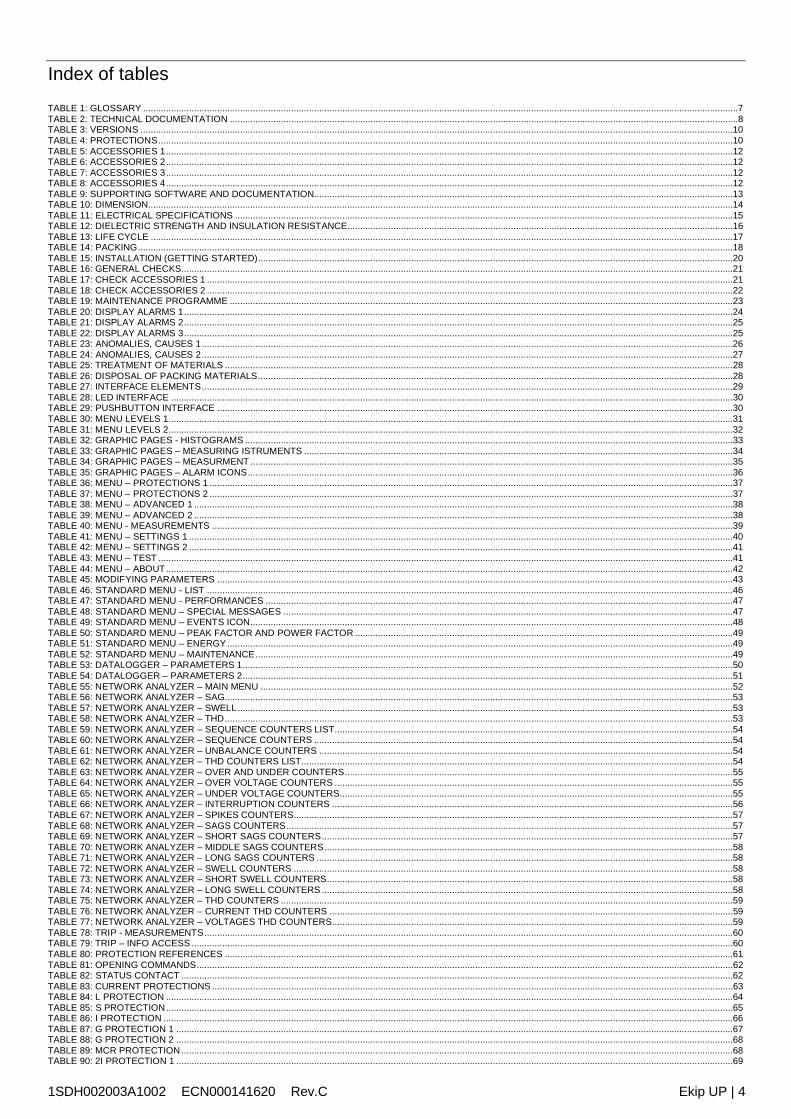
Overview This manual describes the characteristics of Ekip UP, including:1. general overview2. managing operations: receipt, commissioning, maintenance, disposal3. operating conditions4. consulting menu to modify parameters and view measurements5. accessories
Recipients In accordance with standard IEC 60050, this manual is aimed at two user profiles: expert persons, in electric environment (IEV 195-04-01): persons with sufficient training and
experience to enable them to perceive the risks and avoid the hazards potentially createdby electricity
persons trained in an electrical environment (IEV 195-04-02): persons suitably informed orsupervised by electrical technicians to enable them to perceive the risks and avoid thehazards potentially created by electricity
IMPORTANT: in this manual the tasks are specifically indicated that can beperformed by trained persons in an electrical environment. All the remainingtasks described in the manual must be performed by trained persons in anelectrical environment.ABB accepts no liability for damage to property or personal injury due to failureto comply with the instructions contained in this document.
Distribution andorganization of
information
For optimum installation and configuration of Ekip UP in the plant, the following tasks should beperformed in sequence, which are available and distributed in the technical productdocumentation (user manual, Getting Started and electrical diagrams):
Task number Document
1 Consult the safety notes User Manual (page 9)
2 Check operating conditions User Manual (page 14)
3 Check material received User Manual (page 18)
3 Installation Getting Started 1SDH002004A1001and electrical diagrams for 1SDM000116R0001
4 Parameters configuration User manual (from page 37)
5 Test and commissioning Getting Started 1SDH002004A1001and user manual (page 21)
Table 2: technical documentation
Production notes The information in this document have been written in Italian and has then been translated intoother languages to meet legislative and/or commercial product needs.
1SDH002003A1002 ECN000141620 Rev.C Ekip UP | 9
2 - Safety
Safetyprescriptions
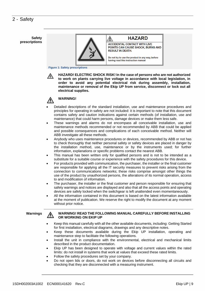
Figure 1: Safety prescriptions
HAZARD! ELECTRIC SHOCK RISK! In the case of persons who are not authorizedto work on plants carrying live voltage in accordance with local legislation, inorder to avoid any potential electrical risk during assembly, installation,maintenance or removal of the Ekip UP from service, disconnect or lock out allelectrical supplies.
WARNING!
Detailed descriptions of the standard installation, use and maintenance procedures andprinciples for operating in safety are not included: it is important to note that this documentcontains safety and caution indications against certain methods (of installation, use andmaintenance) that could harm persons, damage devices or make them less safe.
These warnings and alarms do not encompass all conceivable installation, use andmaintenance methods recommended or not recommended by ABB that could be appliedand possible consequences and complications of each conceivable method. Neither willABB investigate all these methods.
Anybody who uses maintenance procedures or devices, recommended by ABB or not hasto check thoroughly that neither personal safety or safety devices are placed in danger bythe installation method, use, maintenance or by the instruments used; for furtherinformation, explanations or specific problems contact the nearest ABB.
This manual has been written only for qualified persons and is not to be intended as asubstitute for a suitable course or experience with the safety procedures for this device.
For products provided with communication, the purchaser, the installer or the final customerare responsible for applying all the IT security measures to prevent risks arising from theconnection to communications networks; these risks comprise amongst other things theuse of the product by unauthorized persons, the alterations of its normal operation, accessto and modification of information.
The purchaser, the installer or the final customer and person responsible for ensuring thatsafety warnings and notices are displayed and also that all the access points and operatingdevices are safely locked when the switchgear is left unattended even momentaneously.
All the information contained in this document is based on the latest information availableat the moment of publication. We reserve the right to modify the document at any momentwithout prior notice.
Warnings WARNING! READ THE FOLLOWING MANUAL CAREFULLY BEFORE INSTALLINGOR WORKING ON EKIP UP
Keep this manual carefully with all the other available documents, including: Getting Startedfor first installation, electrical diagrams, drawings and any descriptive notes.
Keep these documents available during the Ekip UP installation, operating andmaintenance step to facilitate the following operations.
Install the unit in compliance with the environmental, electrical and mechanical limitsdescribed in the product documentation.
Ekip UP has been designed to operate with voltage and current values within the ratedlimits: do not install in systems that work at values that exceed these rated limits.
Follow the safety procedures set by your company. Do not open lids or doors, do not work on devices before disconnecting all circuits and
checking that they are disconnected with a measuring instrument.
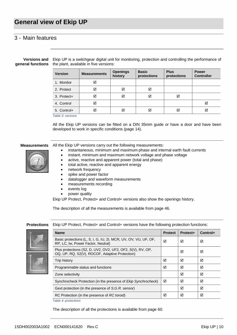
1SDH002003A1002 ECN000141620 Rev.C Ekip UP | 10
General view of Ekip UP
3 - Main features
Versions andgeneral functions
Ekip UP is a switchgear digital unit for monitoring, protection and controlling the performance ofthe plant, available in five versions:
Version Measurements Openingshistory
Basicprotections
Plusprotections
PowerController
1. Monitor
2. Protect
3. Protect+
4. Control
5. Control+
Table 3: versions
All the Ekip UP versions can be fitted on a DIN 35mm guide or have a door and have beendeveloped to work in specific conditions (page 14).
Measurements All the Ekip UP versions carry out the following measurements: instantaneous, minimum and maximum phase and internal earth fault currents instant, minimum and maximum network voltage and phase voltage active, reactive and apparent power (total and phase) total active, reactive and apparent energy network frequency spike and power factor datalogger and waveform measurements measurements recording events log power quality
Ekip UP Protect, Protect+ and Control+ versions also show the openings history.
The description of all the measurements is available from page 46.
Protections Ekip UP Protect, Protect+ and Control+ versions have the following protection functions:
Name Protect Protect+ Control+
Basic protections (L, S, I, G, IU, 2I, MCR, UV, OV, VU, UF, OF,RP, LC, Iw, Power Factor, Neutral)
Plus protections (S2, D, UV2, OV2, UF2, OF2, S(V), RV, OP,OQ, UP, RQ, S2(V), ROCOF, Adaptive Protection)
Trip history
Programmable status and functions
Zone selectivity
Synchrocheck Protection (in the presence of Ekip Synchrocheck)
Gext protection (in the presence of S.G.R. sensor)
RC Protection (in the presence of RC toroid)
Table 4: protections
The description of all the protections is available from page 60.
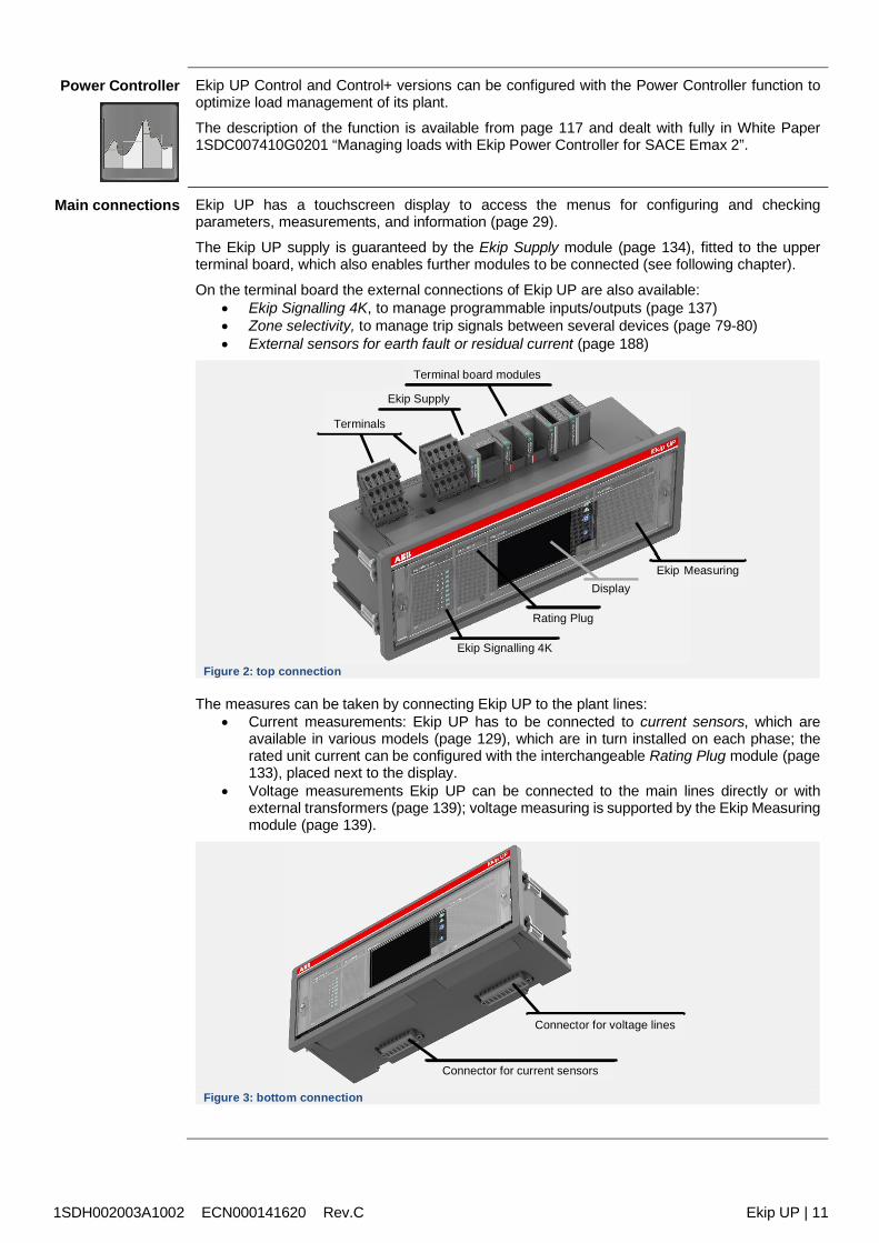
1SDH002003A1002 ECN000141620 Rev.C Ekip UP | 11
Power Controller Ekip UP Control and Control+ versions can be configured with the Power Controller function tooptimize load management of its plant.
The description of the function is available from page 117 and dealt with fully in White Paper1SDC007410G0201 “Managing loads with Ekip Power Controller for SACE Emax 2”.
Main connections Ekip UP has a touchscreen display to access the menus for configuring and checkingparameters, measurements, and information (page 29).
The Ekip UP supply is guaranteed by the Ekip Supply module (page 134), fitted to the upperterminal board, which also enables further modules to be connected (see following chapter).
On the terminal board the external connections of Ekip UP are also available: Ekip Signalling 4K, to manage programmable inputs/outputs (page 137) Zone selectivity, to manage trip signals between several devices (page 79-80) External sensors for earth fault or residual current (page 188)
Figure 2: top connection
The measures can be taken by connecting Ekip UP to the plant lines: Current measurements: Ekip UP has to be connected to current sensors, which are
available in various models (page 129), which are in turn installed on each phase; therated unit current can be configured with the interchangeable Rating Plug module (page133), placed next to the display.
Voltage measurements Ekip UP can be connected to the main lines directly or withexternal transformers (page 139); voltage measuring is supported by the Ekip Measuringmodule (page 139).
Figure 3: bottom connection
Ekip Signalling 4K
Display
Rating Plug
Terminals
Ekip Measuring
Ekip Supply
Terminal board modules
Connector for voltage lines
Connector for current sensors
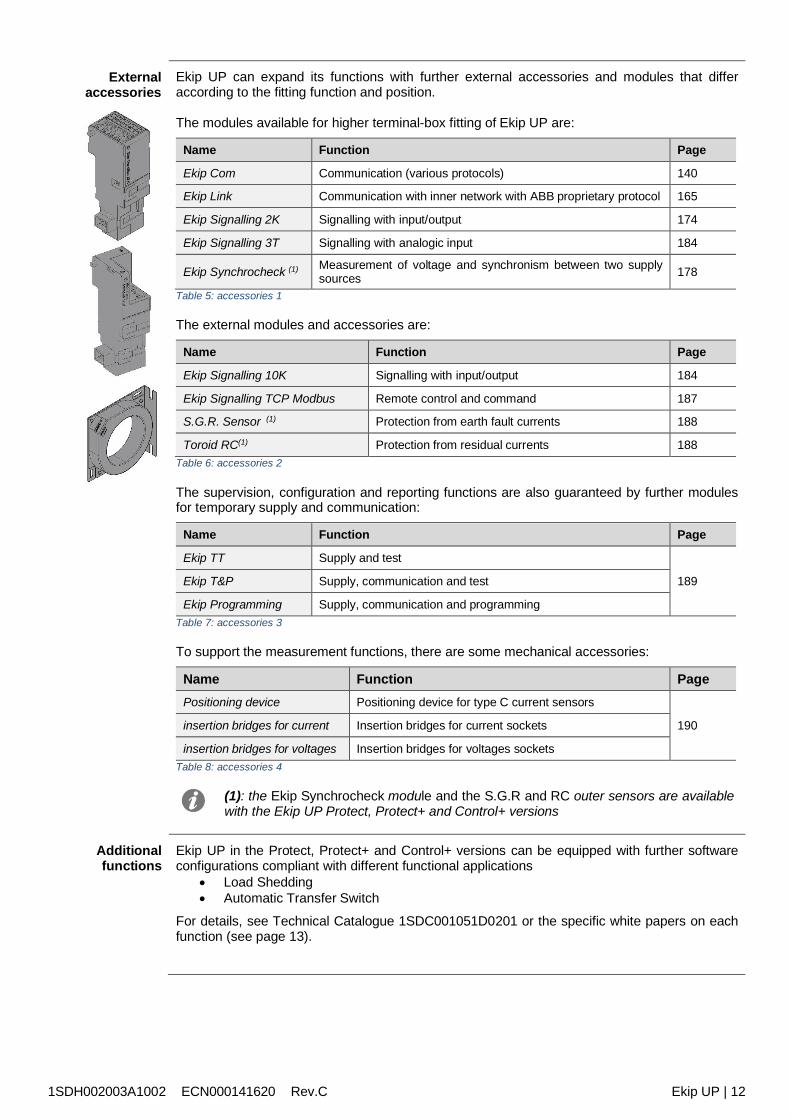
1SDH002003A1002 ECN000141620 Rev.C Ekip UP | 12
Externalaccessories
Ekip UP can expand its functions with further external accessories and modules that differaccording to the fitting function and position.
The modules available for higher terminal-box fitting of Ekip UP are:
Name Function Page
Ekip Com Communication (various protocols) 140
Ekip Link Communication with inner network with ABB proprietary protocol 165
Ekip Signalling 2K Signalling with input/output 174
Ekip Signalling 3T Signalling with analogic input 184
Ekip Synchrocheck (1) Measurement of voltage and synchronism between two supplysources 178
Table 5: accessories 1
The external modules and accessories are:
Name Function Page
Ekip Signalling 10K Signalling with input/output 184
Ekip Signalling TCP Modbus Remote control and command 187
S.G.R. Sensor (1) Protection from earth fault currents 188
Toroid RC(1) Protection from residual currents 188Table 6: accessories 2
The supervision, configuration and reporting functions are also guaranteed by further modulesfor temporary supply and communication:
Name Function Page
Ekip TT Supply and test
189Ekip T&P Supply, communication and test
Ekip Programming Supply, communication and programmingTable 7: accessories 3
To support the measurement functions, there are some mechanical accessories:
Name Function PagePositioning device Positioning device for type C current sensors
190insertion bridges for current Insertion bridges for current sockets
insertion bridges for voltages Insertion bridges for voltages socketsTable 8: accessories 4
(1): the Ekip Synchrocheck module and the S.G.R and RC outer sensors are availablewith the Ekip UP Protect, Protect+ and Control+ versions
Additionalfunctions
Ekip UP in the Protect, Protect+ and Control+ versions can be equipped with further softwareconfigurations compliant with different functional applications
Load Shedding Automatic Transfer Switch
For details, see Technical Catalogue 1SDC001051D0201 or the specific white papers on eachfunction (see page 13).
1SDH002003A1002 ECN000141620 Rev.C Ekip UP | 13
Support softwareand documents
Different software and documents are available, most of which are free of download on ABBLibrary website, to facilitate, optimize and extend functions and configure Ekip UP in its plant:
NOTE: some of the documents specified in the table that follows refer to the deviceSACE Emax 2,whose electronic platform Ekip UP shares.
Name(1) Code Description
Catalogue 1SDC001051D0201 Ekip UP General Catalogue
e-Configure -- On-line tool for configuration and ordering
Ekip Connect 2 /Ekip Connect 3 -- ABB Software for interfacing with Ekip UP and other
low-voltage devices, available in the versione 2 and 3
e-Design --
ABB software suite that comprises the followinginstruments: DOC, to design single-line diagrams of low and
medium voltage electrical installations, choose theoperating and protection device and check andcoordinate protections.
CAT, for technical/commercial quotations for ABBproducts.
Curves for drawing, calibrating and printing trippingcurves of the protection devices
OTC, to check the thermal behaviour of theswitchgears and size fans and air conditioners ofthe switchgear.
UniSec for configuring medium voltageswitchgears
Ekip Link 1SDC200031L0202 Introducing Ekip Link switchgear control system
Network Analyzer1SDC210106D02011SDC200037L0901
Product note Network AnalyzerIntroducing Network Analyzer measuring and analysissystem
Power Controller 1SDC007410G0202 detailed document (White Paper) of the PowerController function.
Adaptive protections 1SDC007116G0201 White paper on adaptive protections
Load Shedding1SDC210105D02011SDC007119G0201
Product note Load SheddingWhite Paper Load Shedding - Priorità distacco carichi
Generator Protectionsand synchronizing
1SDC210108D0201
1SDC007409G0901
Product note on generator protection andsynchronizingWhite Paper on generator protections
Comunicazione 1SDC007412G0202 White paper comunicazione
Ekip Signalling 3T 1SDC210109D0201 Product note Ekip Signalling 3T
Handbook 1SDC010002D0206 General overview of the electrical installationsTable 9: supporting software and documentation
(1): each name or code on table has link that, when connected to an Internet network,directly opens the document described
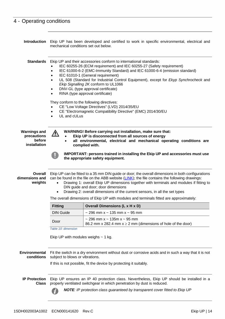
1SDH002003A1002 ECN000141620 Rev.C Ekip UP | 14
4 - Operating conditions
Introduction Ekip UP has been developed and certified to work in specific environmental, electrical andmechanical conditions set out below.
Standards Ekip UP and their accessories conform to international standards: IEC 60255-26 (ECM requirement) and IEC 60255-27 (Safety requirement) IEC 61000-6-2 (EMC-Immunity Standard) and IEC 61000-6-4 (emission standard) IEC 61010-1 (General requirement) UL 508 (Standard for Industrial Control Equipment), except for Ekyp Synchrocheck and
Ekip Signalling 2K conform to UL1066 DNV-GL (type approval certificate) RINA (type approval certificate)
They conform to the following directives: CE "Low Voltage Directives" (LVD) 2014/35/EU CE "Electromagnetic Compatibility Directive" (EMC) 2014/30/EU UL and cULus
Warnings andprecautions
beforeinstallation
WARNING! Before carrying out installation, make sure that: Ekip UP is disconnected from all sources of energy all environmental, electrical and mechanical operating conditions are
complied with.
IMPORTANT: persons trained in installing the Ekip UP and accessories must usethe appropriate safety equipment.
Overalldimensions and
weights
Ekip UP can be fitted to a 35 mm DIN guide or door; the overall dimensions in both configurationscan be found in the file on the ABB website (LINK); the file contains the following drawings:
Drawing 1: overall Ekip UP dimensions together with terminals and modules if fitting toDIN guide and door; door dimensions
Drawing 2: overall dimensions of the current sensors, in all the set types
The overall dimensions of Ekip UP with modules and terminals fitted are approximately:
Fitting Overall Dimensions (L x H x D)DIN Guide ~ 296 mm x ~ 135 mm x ~ 95 mm
Door ~ 296 mm x ~ 135m x ~ 95 mm86.2 mm x 282.4 mm x 2 mm (dimensions of hole of the door)
Table 10: dimension
Ekip UP with modules weighs ~ 1 kg.
Environmentalconditions
Fit the switch in a dry environment without dust or corrosive acids and in such a way that it is notsubject to blows or vibrations.If this is not possible, fit the device by protecting it suitably.
IP ProtectionClass
Ekip UP ensures an IP 40 protection class. Nevertheless, Ekip UP should be installed in aproperly ventilated switchgear in which penetration by dust is reduced.
NOTE: IP protection class guaranteed by transparent cover fitted to Ekip UP
1SDH002003A1002 ECN000141620 Rev.C Ekip UP | 15
Operating andstorage
temperatures
The operating features of Ekip UP and accessories are guaranteed with ambient temperaturebetween -25 °C and +70 °C (+60 °C in application compliant to UL standard)
Depending by type, the current sensors guarantee a correct working in different ambienttemperature:
type A and B: -25 °C ÷ +70 °C type C: -30 °C ÷ +105 °C
Store Ekip UP in a dry dust-free environment that is devoid of corrosive chemical agents; theambient storage temperatures must be ensured, with Ekip UP in the original packaging, between-40 °C and +70 °C.
Particularatmospheric
conditions
Ekip UP can operate in particularly difficult industrial atmospheres. It has been tested inaccordance with: IEC 60068-2-1: dry cold climate IEC 60068-2-2: dry hot climate IEC 60068-2-30: humid hot climate
Mechanicalvibrations
Ekip UP complies with the following mechanical compatibility standards and classes. IEC 60255-21 class 1 (vibrations, shocks and blows), with DIN guide assembly IEC 60255-21 class 2 (vibrations, shocks and blows), with door assembly
Altitude Ekip UP maintains its rated operating features up to 2000 m above sea level.
Above this height, the fall in dielectric strength and the diminished refrigerating power of the airmust be considered (contact ABB for evaluation of details)
Electromagneticcompatibility
The use of specific devices in industrial installations can cause electromagnetic disturbances tothe electrical plant; Ekip UP conforms to Directive 2014/30/EU and to the standards: IEC 60255-26 IEC 61000-6-2 IEC 61000-6-4
WARNING! Full electromagnetic compatibility in accordance with IEC 60255-26 isensured by connecting Ekip UP and Ekip Supply to an ABB model CP-D 24/1,3feeder.
Electricalspecifications
Correct operation of Ekip UP is ensured by primary currents and voltages within well-definedranges and characteristics:
Parameter Operating limits
Primary current 0.03 - 16 In (1)
Primary voltage 0 - 1150 VAC (2)
Rated frequency 50 / 60 Hz ±10 %Table 11: Electrical specifications
NOTES:(1) range refers to each phase. In refers to the rated size defined by the Rating Plug
fitted to the Ekip UP, which is available in 100 A to 6300 A models(2) up to 690 VAC is possible to connected directly the voltages to the device; for
higher voltages, external transformers have to be used, see chapter dedicated toEkip Measuring module on page 139
Auxiliary supply Ekip Supply, supplied as standard with Ekip UP, to enable the unit to be supplied and the terminalboard modules to be connected; see the dedicated chapter on page 134 for functioning details.
1SDH002003A1002 ECN000141620 Rev.C Ekip UP | 16
Dielectricstrength and
insulationresistance
Ekip UP conforms to directive 2014/30/EU and to the standards: IEC 61010-1 IEC 60255-27 UL 508
Type of strengthand resistance Voltage sockets Auxiliary supply Com
ModulesI/OModules
Continuous 3 kV(1) / 1.5 kV(2) 2 kV(3) / 500 V(4) 500 V 1.5 kV
Pulsed 5 kV(1) / 2.2 kV(2) 5 kV(3) / 1 kV(4) 1 kVTable 12: Dielectric strength and insulation resistance
NOTES:(1) voltage sockets with external transformer conforming to Ekip UP, see page 135 for
details(2) voltage sockets without external transformer(3) with Ekip Supply connected to converter ABB CP-D 24/1.3(4) with Ekip Supply connected to general line 24 48 VDC
The voltage sockets ensure (with transformer) the following degree of insulation: >100 M @500 VDC.
Safety Ekip UP conforms to directive 2014/35/EU and to the standards: IEC 61010-1 IEC 60255-27 UL 508
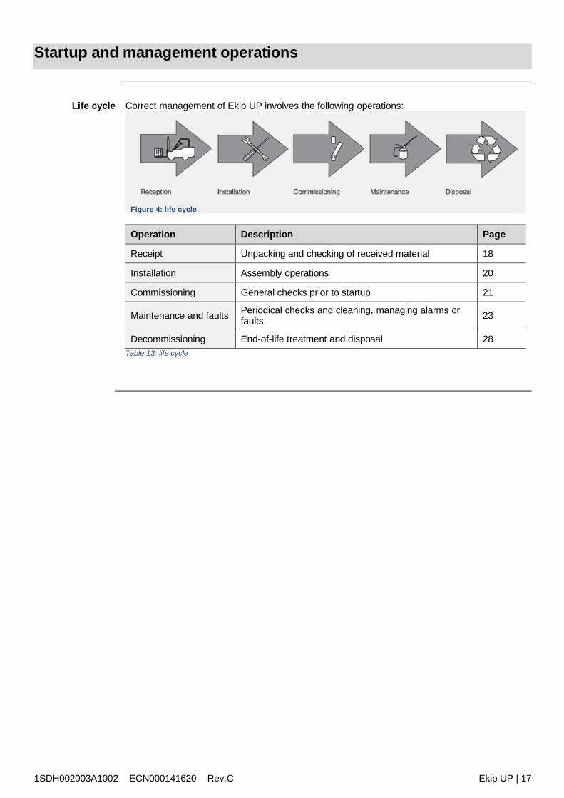
1SDH002003A1002 ECN000141620 Rev.C Ekip UP | 17
Startup and management operations
Life cycle Correct management of Ekip UP involves the following operations:
Figure 4: life cycle
Operation Description Page
Receipt Unpacking and checking of received material 18
Installation Assembly operations 20
Commissioning General checks prior to startup 21
Maintenance and faults Periodical checks and cleaning, managing alarms orfaults 23
Decommissioning End-of-life treatment and disposal 28Table 13: life cycle

1SDH002003A1002 ECN000141620 Rev.C Ekip UP | 18
5 - Receipt
Introduction Every Ekip UP ordered is supplied with the following packing main packing with Ekip UP, terminal board modules and current sensors (if foresee type B,
C and D) packing with current sensors type A, if foresee packing of external accessories modules not mounted on terminal box, if specified in order
The packings are listed ISTA® and have following dimensions: main packing: 460 mm x 347 mm x 154 mm. packing with current sensors type A: 410 mm x 515 mm x 515 mm (supplied on a platform
515 mm x 515 mm)
Identifying andchecking packing
Examine the status of the packing and check that: the information on each packing tag matches the information in the order the boxes are undamaged and completely closed
Figure 5: Identifying and checking packing
Pos. Description
1 Short description of model
2 Description of possible accessories
3 Commercial code
4 Confirmation number
5 Ekip UP serial number
6 Ekip UP characteristicsTable 14: packing
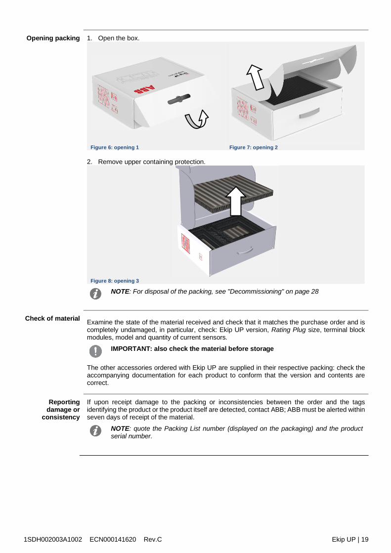
1SDH002003A1002 ECN000141620 Rev.C Ekip UP | 19
Opening packing 1. Open the box.
Figure 6: opening 1 Figure 7: opening 2
2. Remove upper containing protection.
Figure 8: opening 3
NOTE: For disposal of the packing, see "Decommissioning" on page 28
Check of material Examine the state of the material received and check that it matches the purchase order and iscompletely undamaged, in particular, check: Ekip UP version, Rating Plug size, terminal blockmodules, model and quantity of current sensors.
IMPORTANT: also check the material before storage
The other accessories ordered with Ekip UP are supplied in their respective packing: check theaccompanying documentation for each product to conform that the version and contents arecorrect.
Reportingdamage or
consistency
If upon receipt damage to the packing or inconsistencies between the order and the tagsidentifying the product or the product itself are detected, contact ABB; ABB must be alerted withinseven days of receipt of the material.
NOTE: quote the Packing List number (displayed on the packaging) and the productserial number.
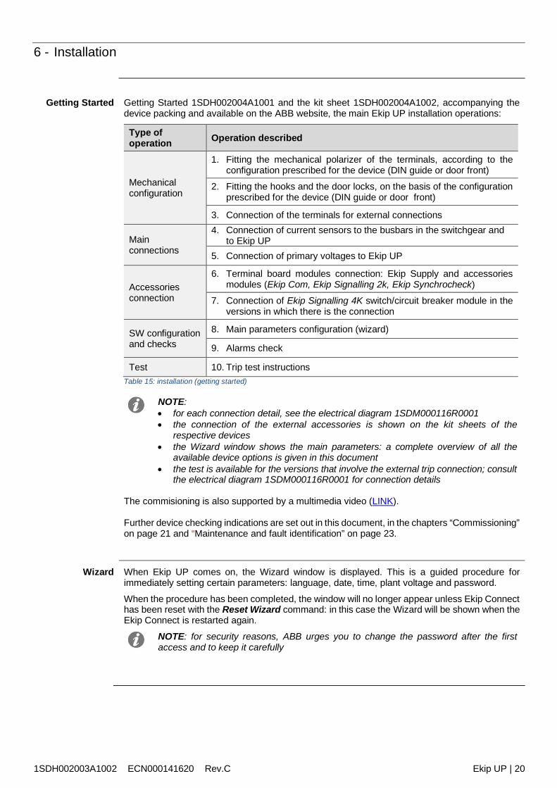
1SDH002003A1002 ECN000141620 Rev.C Ekip UP | 20
6 - Installation
Getting Started Getting Started 1SDH002004A1001 and the kit sheet 1SDH002004A1002, accompanying thedevice packing and available on the ABB website, the main Ekip UP installation operations:
Type ofoperation Operation described
Mechanicalconfiguration
1. Fitting the mechanical polarizer of the terminals, according to theconfiguration prescribed for the device (DIN guide or door front)
2. Fitting the hooks and the door locks, on the basis of the configurationprescribed for the device (DIN guide or door front)
3. Connection of the terminals for external connections
Mainconnections
4. Connection of current sensors to the busbars in the switchgear andto Ekip UP
5. Connection of primary voltages to Ekip UP
Accessoriesconnection
6. Terminal board modules connection: Ekip Supply and accessoriesmodules (Ekip Com, Ekip Signalling 2k, Ekip Synchrocheck)
7. Connection of Ekip Signalling 4K switch/circuit breaker module in theversions in which there is the connection
SW configurationand checks
8. Main parameters configuration (wizard)
9. Alarms check
Test 10. Trip test instructionsTable 15: installation (getting started)
NOTE: for each connection detail, see the electrical diagram 1SDM000116R0001 the connection of the external accessories is shown on the kit sheets of the
respective devices the Wizard window shows the main parameters: a complete overview of all the
available device options is given in this document the test is available for the versions that involve the external trip connection; consult
the electrical diagram 1SDM000116R0001 for connection details
The commisioning is also supported by a multimedia video (LINK).
Further device checking indications are set out in this document, in the chapters “Commissioning”on page 21 and “Maintenance and fault identification” on page 23.
Wizard When Ekip UP comes on, the Wizard window is displayed. This is a guided procedure forimmediately setting certain parameters: language, date, time, plant voltage and password.
When the procedure has been completed, the window will no longer appear unless Ekip Connecthas been reset with the Reset Wizard command: in this case the Wizard will be shown when theEkip Connect is restarted again.
NOTE: for security reasons, ABB urges you to change the password after the firstaccess and to keep it carefully
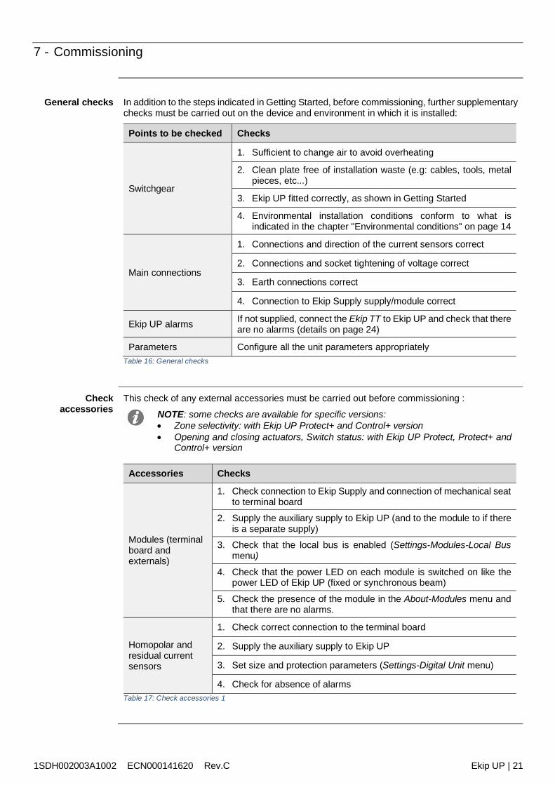
1SDH002003A1002 ECN000141620 Rev.C Ekip UP | 21
7 - Commissioning
General checks In addition to the steps indicated in Getting Started, before commissioning, further supplementarychecks must be carried out on the device and environment in which it is installed:
Points to be checked Checks
Switchgear
1. Sufficient to change air to avoid overheating
2. Clean plate free of installation waste (e.g: cables, tools, metalpieces, etc...)
3. Ekip UP fitted correctly, as shown in Getting Started
4. Environmental installation conditions conform to what isindicated in the chapter "Environmental conditions" on page 14
Main connections
1. Connections and direction of the current sensors correct
2. Connections and socket tightening of voltage correct
3. Earth connections correct
4. Connection to Ekip Supply supply/module correct
Ekip UP alarms If not supplied, connect the Ekip TT to Ekip UP and check that thereare no alarms (details on page 24)
Parameters Configure all the unit parameters appropriatelyTable 16: General checks
Checkaccessories
This check of any external accessories must be carried out before commissioning :
NOTE: some checks are available for specific versions: Zone selectivity: with Ekip UP Protect+ and Control+ version Opening and closing actuators, Switch status: with Ekip UP Protect, Protect+ and
Control+ version
Accessories Checks
Modules (terminalboard andexternals)
1. Check connection to Ekip Supply and connection of mechanical seatto terminal board
2. Supply the auxiliary supply to Ekip UP (and to the module to if thereis a separate supply)
3. Check that the local bus is enabled (Settings-Modules-Local Busmenu)
4. Check that the power LED on each module is switched on like thepower LED of Ekip UP (fixed or synchronous beam)
5. Check the presence of the module in the About-Modules menu andthat there are no alarms.
Homopolar andresidual currentsensors
1. Check correct connection to the terminal board
2. Supply the auxiliary supply to Ekip UP
3. Set size and protection parameters (Settings-Digital Unit menu)
4. Check for absence of alarmsTable 17: Check accessories 1
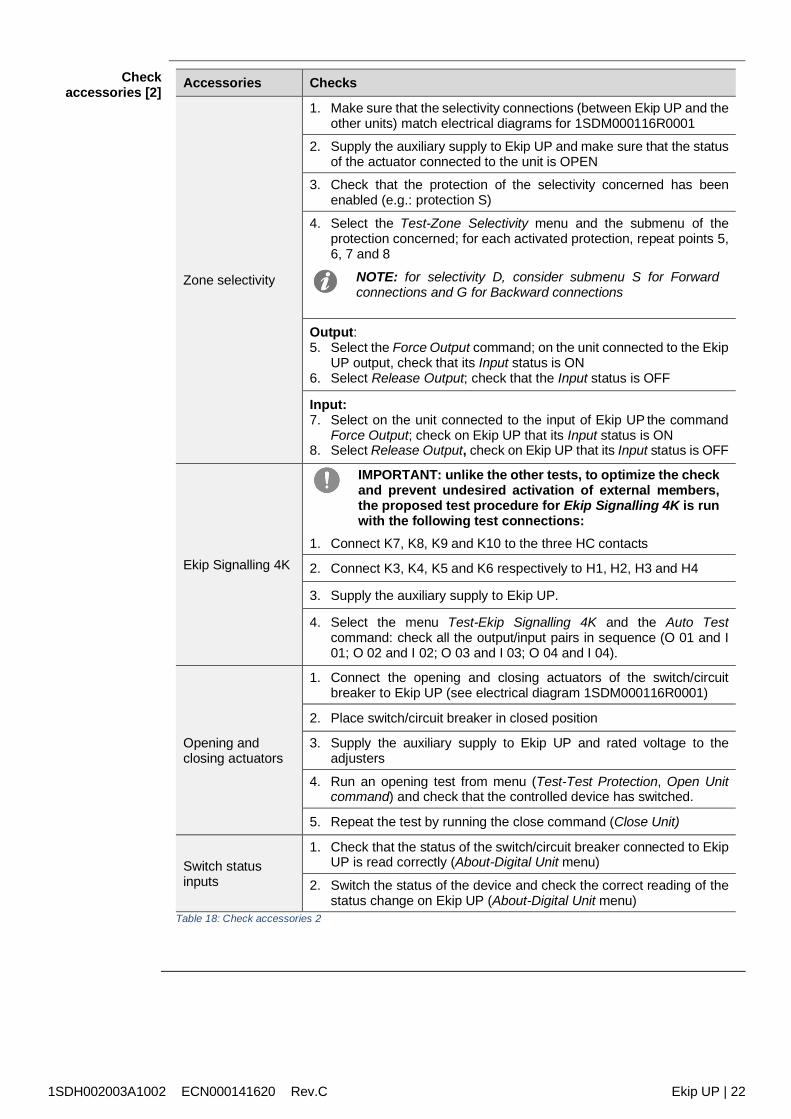
1SDH002003A1002 ECN000141620 Rev.C Ekip UP | 22
Checkaccessories [2] Accessories Checks
Zone selectivity
1. Make sure that the selectivity connections (between Ekip UP and theother units) match electrical diagrams for 1SDM000116R0001
2. Supply the auxiliary supply to Ekip UP and make sure that the statusof the actuator connected to the unit is OPEN
3. Check that the protection of the selectivity concerned has beenenabled (e.g.: protection S)
4. Select the Test-Zone Selectivity menu and the submenu of theprotection concerned; for each activated protection, repeat points 5,6, 7 and 8
NOTE: for selectivity D, consider submenu S for Forwardconnections and G for Backward connections
Output:5. Select the Force Output command; on the unit connected to the Ekip
UP output, check that its Input status is ON6. Select Release Output; check that the Input status is OFF
Input:7. Select on the unit connected to the input of Ekip UP the command
Force Output; check on Ekip UP that its Input status is ON8. Select Release Output, check on Ekip UP that its Input status is OFF
Ekip Signalling 4K
IMPORTANT: unlike the other tests, to optimize the checkand prevent undesired activation of external members,the proposed test procedure for Ekip Signalling 4K is runwith the following test connections:
1. Connect K7, K8, K9 and K10 to the three HC contacts
2. Connect K3, K4, K5 and K6 respectively to H1, H2, H3 and H4
3. Supply the auxiliary supply to Ekip UP.
4. Select the menu Test-Ekip Signalling 4K and the Auto Testcommand: check all the output/input pairs in sequence (O 01 and I01; O 02 and I 02; O 03 and I 03; O 04 and I 04).
Opening andclosing actuators
1. Connect the opening and closing actuators of the switch/circuitbreaker to Ekip UP (see electrical diagram 1SDM000116R0001)
2. Place switch/circuit breaker in closed position
3. Supply the auxiliary supply to Ekip UP and rated voltage to theadjusters
4. Run an opening test from menu (Test-Test Protection, Open Unitcommand) and check that the controlled device has switched.
5. Repeat the test by running the close command (Close Unit)
Switch statusinputs
1. Check that the status of the switch/circuit breaker connected to EkipUP is read correctly (About-Digital Unit menu)
2. Switch the status of the device and check the correct reading of thestatus change on Ekip UP (About-Digital Unit menu)
Table 18: Check accessories 2

1SDH002003A1002 ECN000141620 Rev.C Ekip UP | 23
8 - Maintenance and fault identification
Introduction Correct maintenance of the unit and the connected devices allow its long-term working efficiencyto be maintained.
Maintenance operations must be performed by expert persons (see “Recipients” on page 8) incompliance with safety standards (see “Safety prescriptions” on page 9) and in the maintenanceprogramme.
If there are anomalies or faults, the cause must be identified and eliminated before the unit isstarted up.
WARNING! Before checks, disconnect voltage supply to the auxiliary circuits
Checks andgeneral cleaning
Carry out the following checks1. Check that Ekip UP is clean and if necessary remove any dust or traces of other materials
dry and clean cloths (non-corrosive detergent may be used; in the event of excessivedeposits, a diluent like Henkel 273471 or Chemma 018 or equivalent can be used).
2. Check that there are no foreign bodies near the connectors or terminals.
Ekip UP control Run the checks set out in the chapter “Commissioning” on page 21, to supplement the check ofthe status of the cables and of the accessory modules: check alarms check presence and connection of the modules (terminal board and externals) check Ekip Signalling 4K module check zone selectivity connections check opening and closing actuators check switch status
NOTE: the limits and notes set out for each point in the respective paragraphs must becomplied with
Maintenanceprogramme
The Ekip UP maintenance programme prescribes different frequencies for the maintenance tasksthat depend on the installation environment:
Version Maintenance frequency instandard environments
Maintenance frequency in dustyenvironments (measured dustslevel > 1mg/m3)
Monitor, Control Yearly Every six months
Protect, Protect+,Control+
Once a year or after a short circuittrip
Every six months or after a shortcircuit trip
Table 19: Maintenance programme
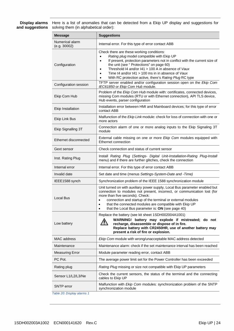
1SDH002003A1002 ECN000141620 Rev.C Ekip UP | 24
Display alarmsand suggestions
Here is a list of anomalies that can be detected from a Ekip UP display and suggestions forsolving them (in alphabetical order):
Message Suggestions
Numerical alarm(e.g. 30002) Internal error. For this type of error contact ABB
Configuration
Check there are these working conditions: Rating plug model compatible with Ekip UP If present, protection parameters not in conflict with the current size of
the unit (see “ Protections” on page 60) Threshold I4 and/or I41 > 100 A in absence of Vaux Time t4 and/or t41 > 100 ms in in absence of Vaux With RC protection active, there’s Rating Plug RC type
Configuration session TFTP server enabled and/or configuration session open on the Ekip ComIEC61850 or Ekip Com Hub module.
Ekip Com HubProblem of the Ekip Com Hub module with: certificates, connected devices,missing Com modules (RTU or with Ethernet connection), API TLS device,Hub events, parser configuration
Ekip Installation Installation error between HMI and Mainboard devices; for this type of errorcontact ABB
Ekip Link Bus Malfunction of the Ekip Link module: check for loss of connection with one ormore actors
Ekip Signalling 3T Connection alarm of one or more analog inputs to the Ekip Signaling 3Tmodule
Ethernet disconnected External cable missing on one or more Ekip Com modules equipped withEthernet connection
Gext sensor Check connection and status of current sensor
Inst. Rating Plug Install Rating Plug (Settings- Digital Unit-Installation-Rating Plug-Installmenu) and if there are further glitches, check the connection
Internal error Internal error. For this type of error contact ABB
Invalid date Set date and time (menus Settings-System-Date and -Time)
IEEE1588 synch Synchronization problem of the IEEE 1588 synchronization module
Local Bus
Unit turned on with auxiliary power supply, Local Bus parameter enabled butconnection to modules not present, incorrect, or communication lost (formore than five seconds). Check: connection and startup of the terminal or external modules that the connected modules are compatible with Ekip UP that the Local Bus parameter is: ON (see page 40)
Low battery
Replace the battery (see kit sheet 1SDH002004A1001)WARNING! battery may explode if mistreated; do notrecharge, disassemble or dispose of in fire.Replace battery with CR2450HR, use of another battery maypresent a risk of fire or explosion.
MAC address Ekip Com module with wrong/unacceptable MAC address detected
Maintenance Maintenance alarm: check if the set maintenance interval has been reached
Measuring Error Module parameter reading error, contact ABB
PC Pot. The average power limit set for the Power Controller has been exceeded
Rating plug Rating Plug missing or size not compatible with Ekip UP parameters
Sensor L1/L2/L3/Ne Check the current sensors, the status of the terminal and the connectingcables to Ekip UP
SNTP error Malfunction with Ekip Com modules: synchronization problem of the SNTPsynchronization module
Table 20: Display alarms 1
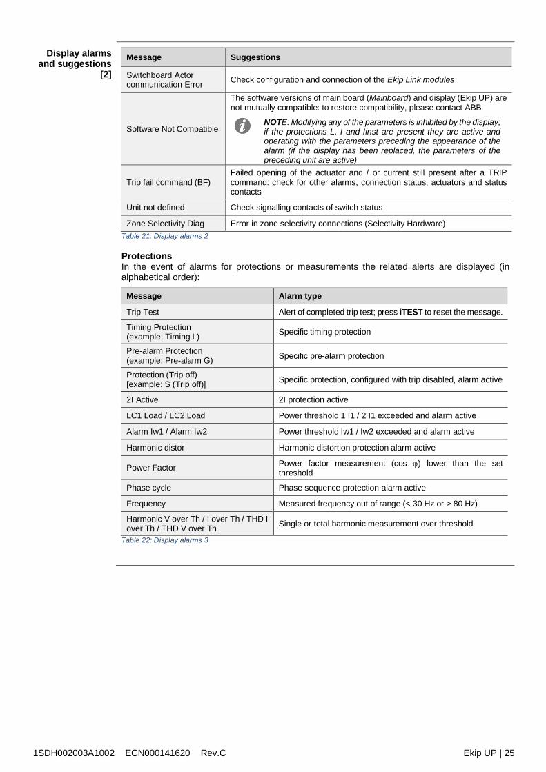
1SDH002003A1002 ECN000141620 Rev.C Ekip UP | 25
Display alarmsand suggestions
[2]
Message Suggestions
Switchboard Actorcommunication Error Check configuration and connection of the Ekip Link modules
Software Not Compatible
The software versions of main board (Mainboard) and display (Ekip UP) arenot mutually compatible: to restore compatibility, please contact ABB
NOTE: Modifying any of the parameters is inhibited by the display;if the protections L, I and Iinst are present they are active andoperating with the parameters preceding the appearance of thealarm (if the display has been replaced, the parameters of thepreceding unit are active)
Trip fail command (BF)Failed opening of the actuator and / or current still present after a TRIPcommand: check for other alarms, connection status, actuators and statuscontacts
Unit not defined Check signalling contacts of switch status
Zone Selectivity Diag Error in zone selectivity connections (Selectivity Hardware)Table 21: Display alarms 2
ProtectionsIn the event of alarms for protections or measurements the related alerts are displayed (inalphabetical order):
Message Alarm type
Trip Test Alert of completed trip test; press iTEST to reset the message.
Timing Protection(example: Timing L) Specific timing protection
Pre-alarm Protection(example: Pre-alarm G) Specific pre-alarm protection
Protection (Trip off)[example: S (Trip off)] Specific protection, configured with trip disabled, alarm active
2I Active 2I protection active
LC1 Load / LC2 Load Power threshold 1 I1 / 2 I1 exceeded and alarm active
Alarm Iw1 / Alarm Iw2 Power threshold Iw1 / Iw2 exceeded and alarm active
Harmonic distor Harmonic distortion protection alarm active
Power Factor Power factor measurement (cos ) lower than the setthreshold
Phase cycle Phase sequence protection alarm active
Frequency Measured frequency out of range (< 30 Hz or > 80 Hz)
Harmonic V over Th / I over Th / THD Iover Th / THD V over Th Single or total harmonic measurement over threshold
Table 22: Display alarms 3
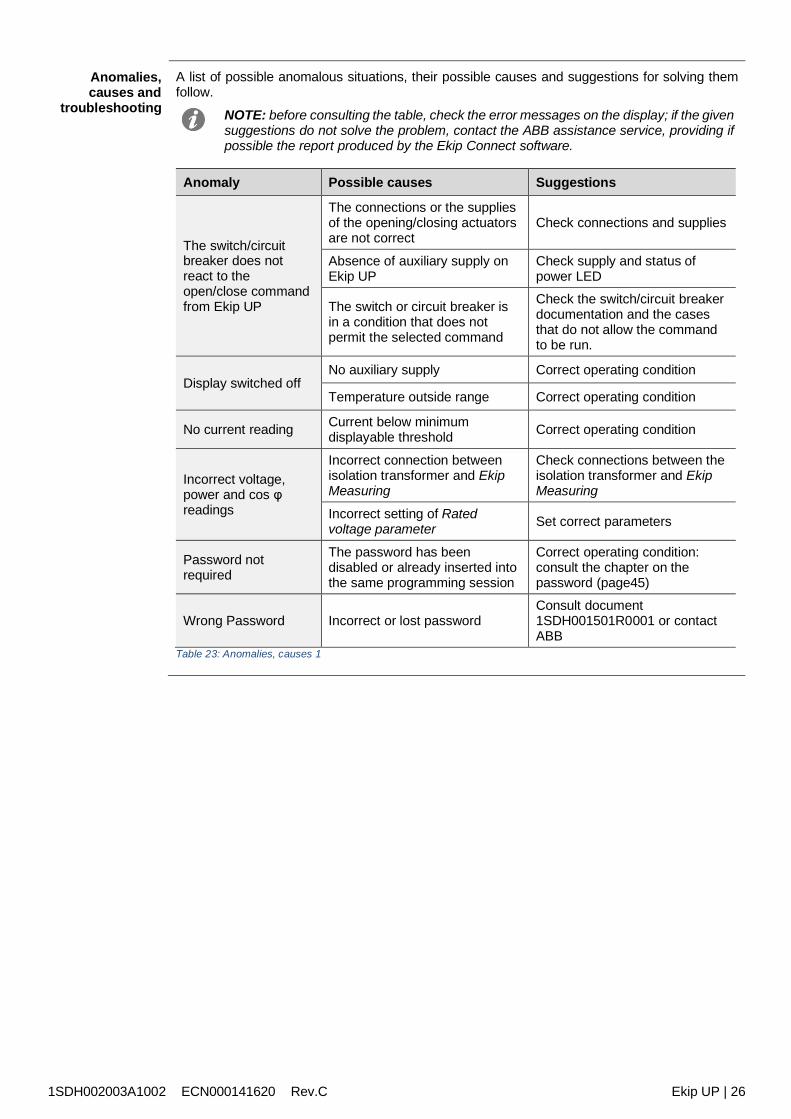
1SDH002003A1002 ECN000141620 Rev.C Ekip UP | 26
Anomalies,causes and
troubleshooting
A list of possible anomalous situations, their possible causes and suggestions for solving themfollow.
NOTE: before consulting the table, check the error messages on the display; if the givensuggestions do not solve the problem, contact the ABB assistance service, providing ifpossible the report produced by the Ekip Connect software.
Anomaly Possible causes Suggestions
The switch/circuitbreaker does notreact to theopen/close commandfrom Ekip UP
The connections or the suppliesof the opening/closing actuatorsare not correct
Check connections and supplies
Absence of auxiliary supply onEkip UP
Check supply and status ofpower LED
The switch or circuit breaker isin a condition that does notpermit the selected command
Check the switch/circuit breakerdocumentation and the casesthat do not allow the commandto be run.
Display switched offNo auxiliary supply Correct operating condition
Temperature outside range Correct operating condition
No current reading Current below minimumdisplayable threshold Correct operating condition
Incorrect voltage,power and cos φreadings
Incorrect connection betweenisolation transformer and EkipMeasuring
Check connections between theisolation transformer and EkipMeasuring
Incorrect setting of Ratedvoltage parameter Set correct parameters
Password notrequired
The password has beendisabled or already inserted intothe same programming session
Correct operating condition:consult the chapter on thepassword (page45)
Wrong Password Incorrect or lost passwordConsult document1SDH001501R0001 or contactABB
Table 23: Anomalies, causes 1
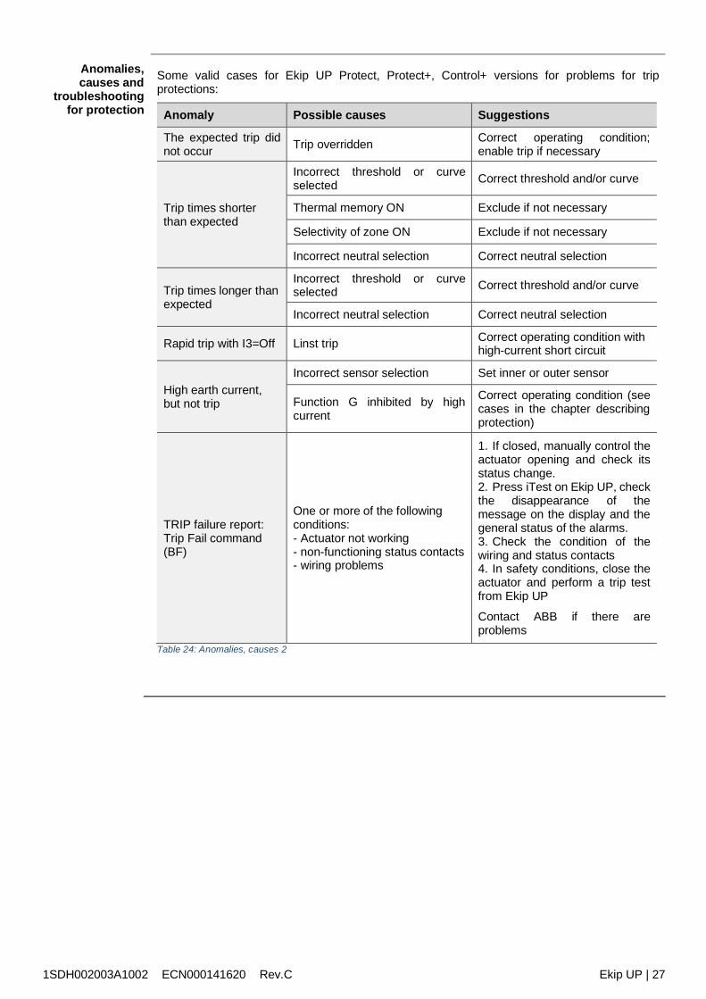
1SDH002003A1002 ECN000141620 Rev.C Ekip UP | 27
Anomalies,causes and
troubleshootingfor protection
Some valid cases for Ekip UP Protect, Protect+, Control+ versions for problems for tripprotections:
Anomaly Possible causes Suggestions
The expected trip didnot occur Trip overridden Correct operating condition;
enable trip if necessary
Trip times shorterthan expected
Incorrect threshold or curveselected Correct threshold and/or curve
Thermal memory ON Exclude if not necessary
Selectivity of zone ON Exclude if not necessary
Incorrect neutral selection Correct neutral selection
Trip times longer thanexpected
Incorrect threshold or curveselected Correct threshold and/or curve
Incorrect neutral selection Correct neutral selection
Rapid trip with I3=Off Linst trip Correct operating condition withhigh-current short circuit
High earth current,but not trip
Incorrect sensor selection Set inner or outer sensor
Function G inhibited by highcurrent
Correct operating condition (seecases in the chapter describingprotection)
TRIP failure report:Trip Fail command(BF)
One or more of the followingconditions:- Actuator not working- non-functioning status contacts- wiring problems
1. If closed, manually control theactuator opening and check itsstatus change.2. Press iTest on Ekip UP, checkthe disappearance of themessage on the display and thegeneral status of the alarms.3. Check the condition of thewiring and status contacts4. In safety conditions, close theactuator and perform a trip testfrom Ekip UP
Contact ABB if there areproblems
Table 24: Anomalies, causes 2

1SDH002003A1002 ECN000141620 Rev.C Ekip UP | 28
9 - Decommissioning
Introduction Decommissioning operations must be performed by expert persons (see “Recipients” on page 8)in compliance with safety standards (see “Safety prescriptions” on page 9) and the notes ontreatment at the end of life and disposal set out below.
WARNING! Before decommissioning, disconnect and lock out auxiliary circuits.
NOTE: refer to the national regulations governing the decommissioning of the productif the decommissioning involves end-of-life treatment procedures other than thoseindicated
End-of-lifetreatment of
materials
The materials used to make the Ekip UP units can be recycled and must be sorted into categoriesas shown in the following table:
Type Material
A Plastic parts
B Mechanical parts
C Printed circuits
D Current sensors and cablesTable 25: treatment of materials
NOTE: plastic parts of significant dimensions display marking showing the type ofmaterial.
Disposal ofpacking materials
The materials used for Ekip UP packing can be recycled and must be sorted into categories asshown in the following table:
Type Material
A Plastic parts
B Cardboard partsTable 26: Disposal of packing materials
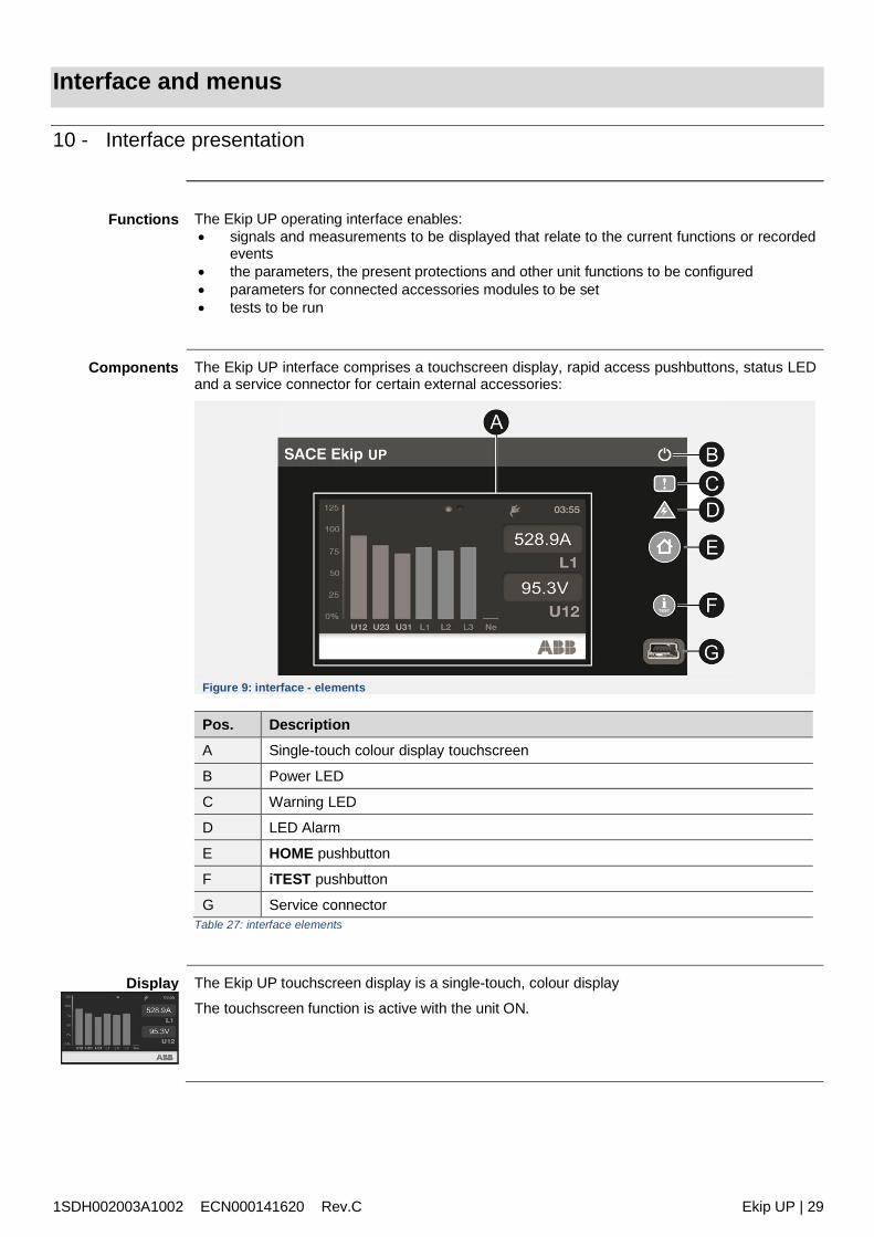
1SDH002003A1002 ECN000141620 Rev.C Ekip UP | 29
Interface and menus
10 - Interface presentation
Functions The Ekip UP operating interface enables: signals and measurements to be displayed that relate to the current functions or recorded
events the parameters, the present protections and other unit functions to be configured parameters for connected accessories modules to be set tests to be run
Components The Ekip UP interface comprises a touchscreen display, rapid access pushbuttons, status LEDand a service connector for certain external accessories:
Figure 9: interface - elements
Pos. DescriptionA Single-touch colour display touchscreen
B Power LED
C Warning LED
D LED Alarm
E HOME pushbutton
F iTEST pushbutton
G Service connectorTable 27: interface elements
Display The Ekip UP touchscreen display is a single-touch, colour display
The touchscreen function is active with the unit ON.
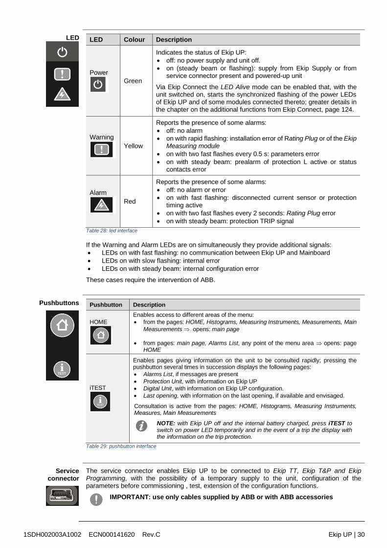
1SDH002003A1002 ECN000141620 Rev.C Ekip UP | 30
LED LED Colour Description
PowerGreen
Indicates the status of Ekip UP: off: no power supply and unit off. on (steady beam or flashing): supply from Ekip Supply or from
service connector present and powered-up unit
Via Ekip Connect the LED Alive mode can be enabled that, with theunit switched on, starts the synchronized flashing of the power LEDsof Ekip UP and of some modules connected thereto; greater details inthe chapter on the additional functions from Ekip Connect, page 124.
WarningYellow
Reports the presence of some alarms: off: no alarm on with rapid flashing: installation error of Rating Plug or of the Ekip
Measuring module on with two fast flashes every 0.5 s: parameters error on with steady beam: prealarm of protection L active or status
contacts error
AlarmRed
Reports the presence of some alarms: off: no alarm or error on with fast flashing: disconnected current sensor or protection
timing active on with two fast flashes every 2 seconds: Rating Plug error on with steady beam: protection TRIP signal
Table 28: led interface
If the Warning and Alarm LEDs are on simultaneously they provide additional signals: LEDs on with fast flashing: no communication between Ekip UP and Mainboard LEDs on with slow flashing: internal error LEDs on with steady beam: internal configuration error
These cases require the intervention of ABB.
Pushbuttons Pushbutton Description
HOMEEnables access to different areas of the menu: from the pages: HOME, Histograms, Measuring Instruments, Measurements, Main
Measurements opens: main page
from pages: main page, Alarms List, any point of the menu area opens: pageHOME
iTEST
Enables pages giving information on the unit to be consulted rapidly; pressing thepushbutton several times in succession displays the following pages: Alarms List, if messages are present Protection Unit, with information on Ekip UP Digital Unit, with information on Ekip UP configuration. Last opening, with information on the last opening, if available and envisaged.
Consultation is active from the pages: HOME, Histograms, Measuring Instruments,Measures, Main Measurements
NOTE: with Ekip UP off and the internal battery charged, press iTEST toswitch on power LED temporarily and in the event of a trip the display withthe information on the trip protection.
Table 29: pushbutton interface
Serviceconnector
The service connector enables Ekip UP to be connected to Ekip TT, Ekip T&P and EkipProgramming, with the possibility of a temporary supply to the unit, configuration of theparameters before commissioning , test, extension of the configuration functions.
IMPORTANT: use only cables supplied by ABB or with ABB accessories
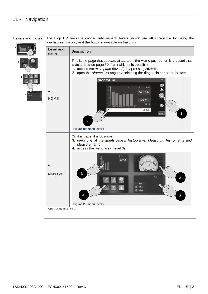
1SDH002003A1002 ECN000141620 Rev.C Ekip UP | 31
11 - Navigation
Levels and pages The Ekip UP menu is divided into several levels, which are all accessible by using thetouchscreen display and the buttons available on the units
Level andname Description
1
HOME
This is the page that appears at startup if the Home pushbutton is pressed thatis described on page 30; from which it is possible to:1. access the main page (level 2), by pressing HOME2. open the Alarms List page by selecting the diagnosis bar at the bottom
Figure 10: menu level 1
2
MAIN PAGE
On this page, it is possible:3. open one of the graph pages: Histograms, Measuring Instruments and
Measurements4. access the menu area (level 3)
Figure 11: menu level 2Table 30: menu levels 1
1
2
3
4 3
3
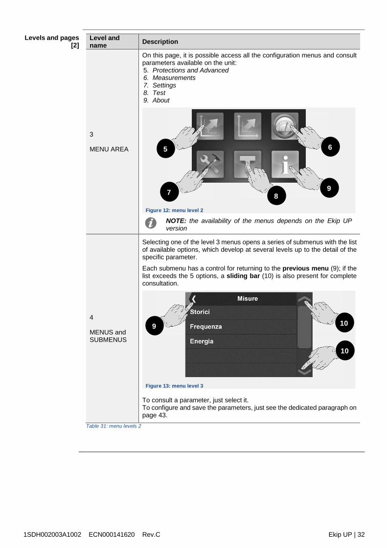
1SDH002003A1002 ECN000141620 Rev.C Ekip UP | 32
Levels and pages[2]
Level andname Description
3
MENU AREA
On this page, it is possible access all the configuration menus and consultparameters available on the unit:5. Protections and Advanced6. Measurements7. Settings8. Test9. About
Figure 12: menu level 2
NOTE: the availability of the menus depends on the Ekip UPversion
4
MENUS andSUBMENUS
Selecting one of the level 3 menus opens a series of submenus with the listof available options, which develop at several levels up to the detail of thespecific parameter.
Each submenu has a control for returning to the previous menu (9); if thelist exceeds the 5 options, a sliding bar (10) is also present for completeconsultation.
Figure 13: menu level 3
To consult a parameter, just select it.To configure and save the parameters, just see the dedicated paragraph onpage 43.
Table 31: menu levels 2
5
7 89
6
9 10
10
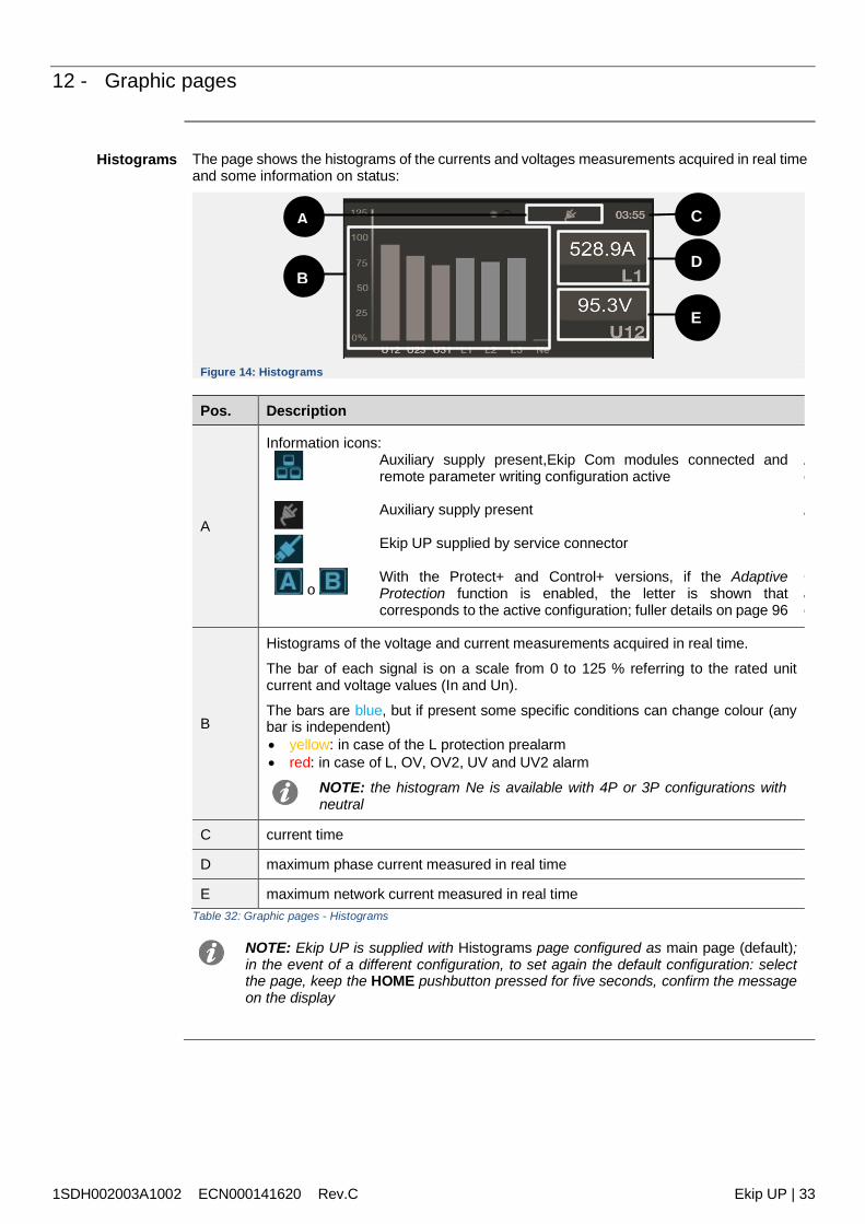
1SDH002003A1002 ECN000141620 Rev.C Ekip UP | 33
12 - Graphic pages
Histograms The page shows the histograms of the currents and voltages measurements acquired in real timeand some information on status:
Figure 14: Histograms
Pos. Description
A
Information icons:Auxiliary supply present,Ekip Com modules connected andremote parameter writing configuration active
Alimentazione ausiliaria presente, moduli Ekip Com connessi econfigurazione scrittura parametri da remoto attiva
Auxiliary supply present Alimentazione ausiliaria presente
Ekip UP supplied by service connector Ekip UP alimentato da
oWith the Protect+ and Control+ versions, if the AdaptiveProtection function is enabled, the letter is shown thatcorresponds to the active configuration; fuller details on page 96
Con versioni Protect+ e Control+, se la funzioneadattativeconfigurazione attiva; maggiori dettagli a pagina
B
Histograms of the voltage and current measurements acquired in real time.
The bar of each signal is on a scale from 0 to 125 % referring to the rated unitcurrent and voltage values (In and Un).
The bars are blue, but if present some specific conditions can change colour (anybar is independent) yellow: in case of the L protection prealarm red: in case of L, OV, OV2, UV and UV2 alarm
NOTE: the histogram Ne is available with 4P or 3P configurations withneutral
C current time
D maximum phase current measured in real time
E maximum network current measured in real timeTable 32: Graphic pages - Histograms
NOTE: Ekip UP is supplied with Histograms page configured as main page (default);in the event of a different configuration, to set again the default configuration: selectthe page, keep the HOME pushbutton pressed for five seconds, confirm the messageon the display
B
A C
D
E
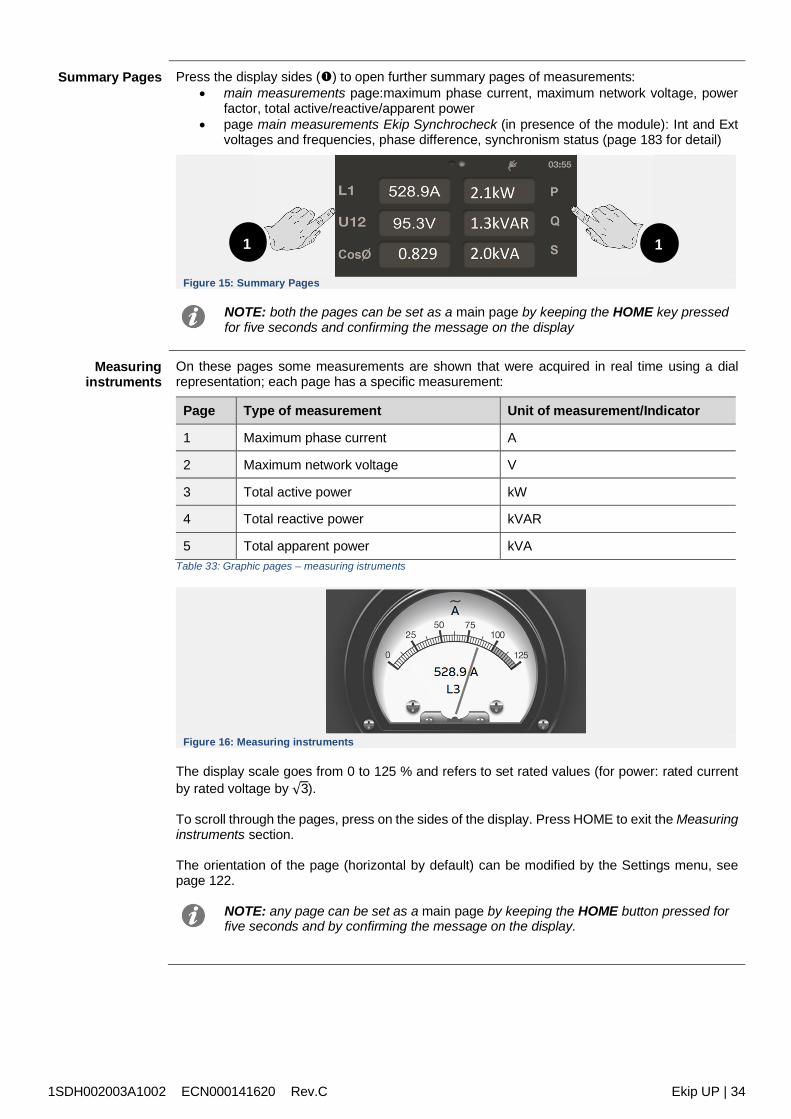
1SDH002003A1002 ECN000141620 Rev.C Ekip UP | 34
Summary Pages Press the display sides () to open further summary pages of measurements: main measurements page:maximum phase current, maximum network voltage, power
factor, total active/reactive/apparent power page main measurements Ekip Synchrocheck (in presence of the module): Int and Ext
voltages and frequencies, phase difference, synchronism status (page 183 for detail)
Figure 15: Summary Pages
NOTE: both the pages can be set as a main page by keeping the HOME key pressedfor five seconds and confirming the message on the display
Measuringinstruments
On these pages some measurements are shown that were acquired in real time using a dialrepresentation; each page has a specific measurement:
Page Type of measurement Unit of measurement/Indicator
1 Maximum phase current A
2 Maximum network voltage V
3 Total active power kW
4 Total reactive power kVAR
5 Total apparent power kVATable 33: Graphic pages – measuring istruments
Figure 16: Measuring instruments
The display scale goes from 0 to 125 % and refers to set rated values (for power: rated currentby rated voltage by √3).
To scroll through the pages, press on the sides of the display. Press HOME to exit the Measuringinstruments section.
The orientation of the page (horizontal by default) can be modified by the Settings menu, seepage 122.
NOTE: any page can be set as a main page by keeping the HOME button pressed forfive seconds and by confirming the message on the display.
1 1
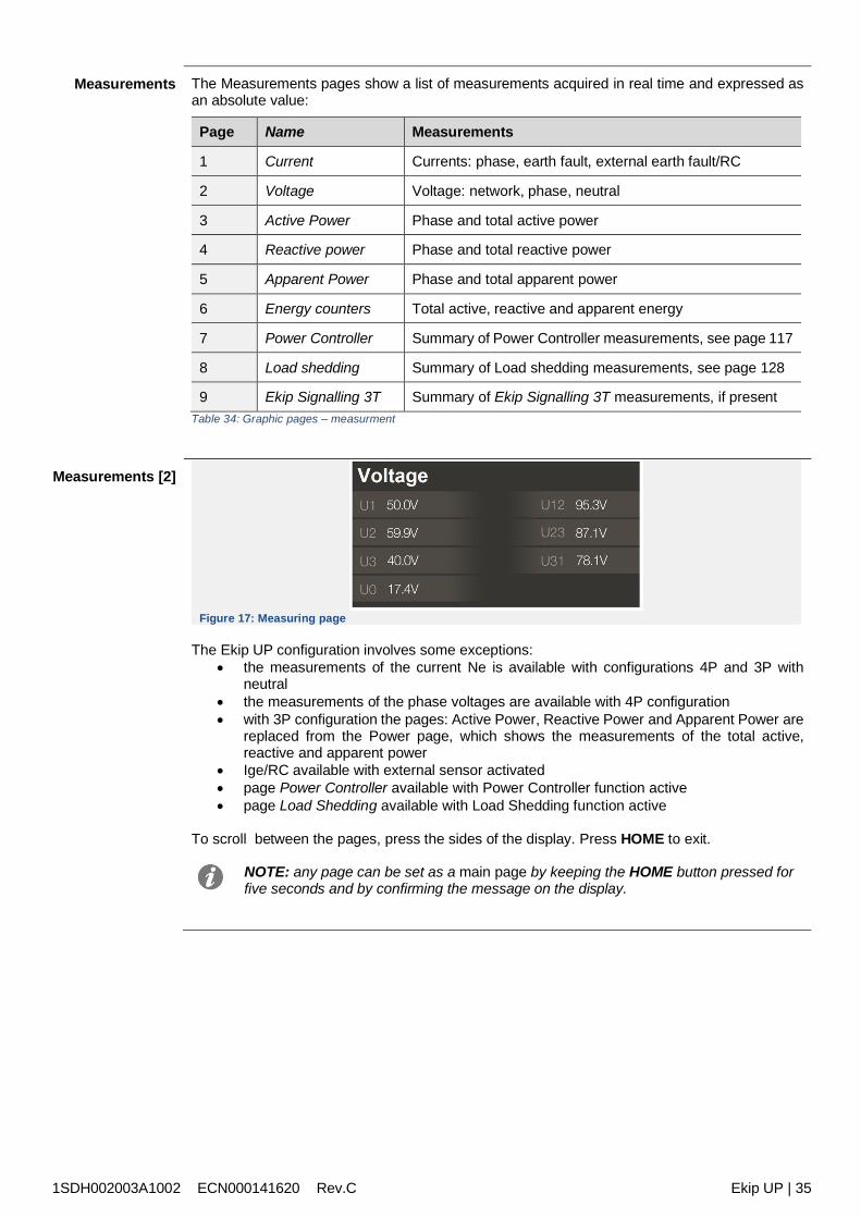
1SDH002003A1002 ECN000141620 Rev.C Ekip UP | 35
Measurements The Measurements pages show a list of measurements acquired in real time and expressed asan absolute value:
Page Name Measurements
1 Current Currents: phase, earth fault, external earth fault/RC
2 Voltage Voltage: network, phase, neutral
3 Active Power Phase and total active power
4 Reactive power Phase and total reactive power
5 Apparent Power Phase and total apparent power
6 Energy counters Total active, reactive and apparent energy
7 Power Controller Summary of Power Controller measurements, see page 117
8 Load shedding Summary of Load shedding measurements, see page 128
9 Ekip Signalling 3T Summary of Ekip Signalling 3T measurements, if presentTable 34: Graphic pages – measurment
Measurements [2]
Figure 17: Measuring page
The Ekip UP configuration involves some exceptions: the measurements of the current Ne is available with configurations 4P and 3P with
neutral the measurements of the phase voltages are available with 4P configuration with 3P configuration the pages: Active Power, Reactive Power and Apparent Power are
replaced from the Power page, which shows the measurements of the total active,reactive and apparent power
Ige/RC available with external sensor activated page Power Controller available with Power Controller function active page Load Shedding available with Load Shedding function active
To scroll between the pages, press the sides of the display. Press HOME to exit.
NOTE: any page can be set as a main page by keeping the HOME button pressed forfive seconds and by confirming the message on the display.
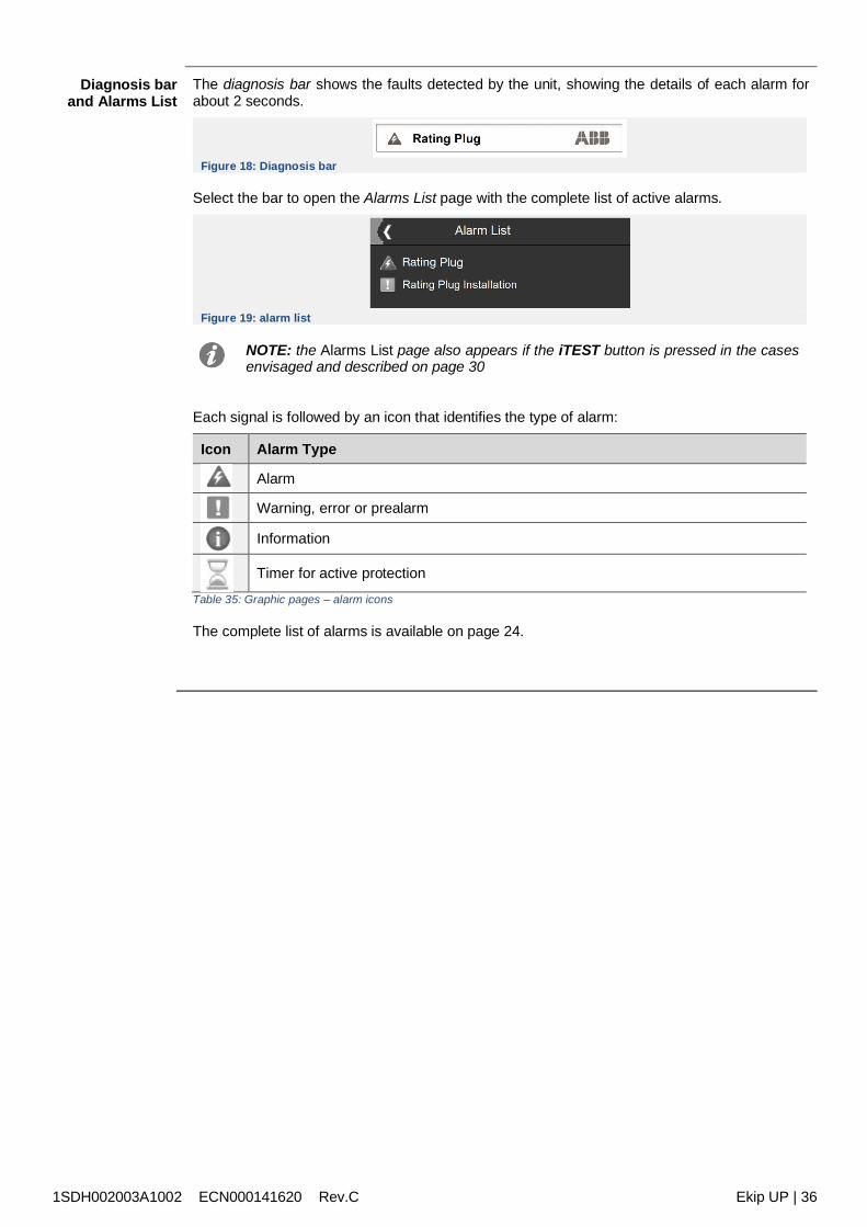
1SDH002003A1002 ECN000141620 Rev.C Ekip UP | 36
Diagnosis barand Alarms List
The diagnosis bar shows the faults detected by the unit, showing the details of each alarm forabout 2 seconds.
Figure 18: Diagnosis bar
Select the bar to open the Alarms List page with the complete list of active alarms.
Figure 19: alarm list
NOTE: the Alarms List page also appears if the iTEST button is pressed in the casesenvisaged and described on page 30
Each signal is followed by an icon that identifies the type of alarm:
Icon Alarm Type
Alarm
Warning, error or prealarm
Information
Timer for active protection
Table 35: Graphic pages – alarm icons
The complete list of alarms is available on page 24.
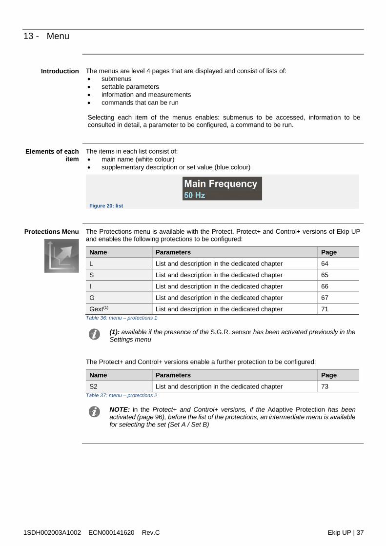
1SDH002003A1002 ECN000141620 Rev.C Ekip UP | 37
13 - Menu
Introduction The menus are level 4 pages that are displayed and consist of lists of: submenus settable parameters information and measurements commands that can be run
Selecting each item of the menus enables: submenus to be accessed, information to beconsulted in detail, a parameter to be configured, a command to be run.
Elements of eachitem
The items in each list consist of: main name (white colour) supplementary description or set value (blue colour)
Figure 20: list
Protections Menu The Protections menu is available with the Protect, Protect+ and Control+ versions of Ekip UPand enables the following protections to be configured:
Name Parameters PageL List and description in the dedicated chapter 64
S List and description in the dedicated chapter 65
I List and description in the dedicated chapter 66
G List and description in the dedicated chapter 67
Gext(1) List and description in the dedicated chapter 71Table 36: menu – protections 1
(1): available if the presence of the S.G.R. sensor has been activated previously in theSettings menu
The Protect+ and Control+ versions enable a further protection to be configured:
Name Parameters PageS2 List and description in the dedicated chapter 73
Table 37: menu – protections 2
NOTE: in the Protect+ and Control+ versions, if the Adaptive Protection has beenactivated (page 96), before the list of the protections, an intermediate menu is availablefor selecting the set (Set A / Set B)
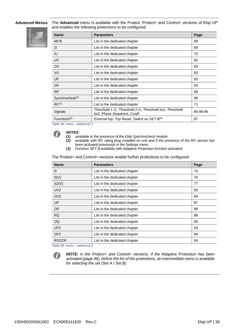
1SDH002003A1002 ECN000141620 Rev.C Ekip UP | 38
Advanced Menus The Advanced menu is available with the Protect, Protect+ and Control+ versions of Ekip UPand enables the following protections to be configured:
Name Parameters PageMCR List in the dedicated chapter 68
2I List in the dedicated chapter 69
IU List in the dedicated chapter 70
UV List in the dedicated chapter 82
OV List in the dedicated chapter 83
VU List in the dedicated chapter 83
UF List in the dedicated chapter 92
OF List in the dedicated chapter 93
RP List in the dedicated chapter 88
Synchrocheck(1) List in the dedicated chapter 98
RC(2) List in the dedicated chapter 71
Signals Threshold 1 I1, Threshold 2 I1, Threshold Iw1, ThresholdIw2, Phase Sequence, CosØ 85-96-96
Functions(3) External trip, Trip Reset, Switch on SET B(3) 97Table 38: menu – advanced 1
NOTES:(1) available in the presence of the Ekip Synchrocheck module(2) available with RC rating plug installed on unit and if the presence of the RC sensor has
been activated previously in the Settings menu(3) Function SET B available with Adaptive Protection function activated
The Protect+ and Control+ versions enable further protections to be configured:
Name Parameters PageD List in the dedicated chapter 74
S(V) List in the dedicated chapter 76
S2(V) List in the dedicated chapter 77
UV2 List in the dedicated chapter 83
OV2 List in the dedicated chapter 84
UP List in the dedicated chapter 87
OP List in the dedicated chapter 88
RQ List in the dedicated chapter 88
OQ List in the dedicated chapter 90
UF2 List in the dedicated chapter 93
OF2 List in the dedicated chapter 94
ROCOF List in the dedicated chapter 94Table 39: menu – advanced 2
NOTE: in the Protect+ and Control+ versions, if the Adaptive Protection has beenactivated (page 96), before the list of the protections, an intermediate menu is availablefor selecting the set (Set A / Set B)

1SDH002003A1002 ECN000141620 Rev.C Ekip UP | 39
MeasurementsMenu Menu Submenu Description Page
Historicals
Openings(1) Description in the dedicated chapter 60
Events List of the recorded events 48
Measurements List and description in the dedicatedchapter 48
Power factor -- Power factor measurement 49
Frequency -- Measured frequency 47
Energy
Energy counters Energy measurement47
Reset Counters Counters reset command
Energy RESET List and description in the dedicatedchapter 98
Peak factor -- Peak factor of each phase 49
Harmonic dist. -- Command to activate control ofharmonic distortion of the currents 96
Ekip Synchrocheck Description in the dedicated chapter 182
Network Analyzer(2)
Sequence V
Measurements associated with theNetwork Analyzer function: list anddescription in the dedicated chapter
52
Sequence V 3s
THD Current
THD Voltages
Counters
Waveforms
Maintenance
InstallationInstallation and maintenance datesand commands 49Last maintenance
Service RESETTable 40: menu - measurements
NOTES:(1) available with Protect, Protect+ and Control+ versions(2) available with the Network Analyzer function that was activated in the Settings
menu
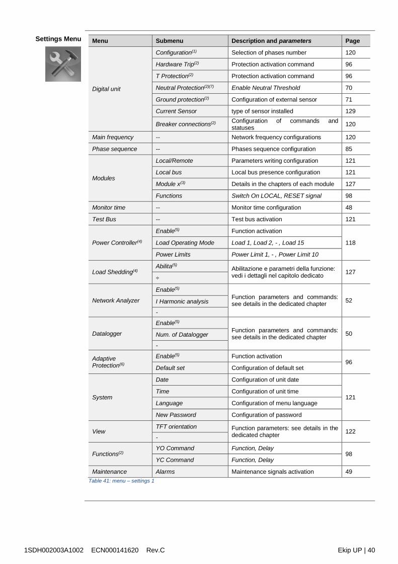
1SDH002003A1002 ECN000141620 Rev.C Ekip UP | 40
Settings Menu Menu Submenu Description and parameters Page
Digital unit
Configuration(1) Selection of phases number 120
Hardware Trip(2) Protection activation command 96
T Protection(2) Protection activation command 96
Neutral Protection(2)(7) Enable Neutral Threshold 70
Ground protection(2) Configuration of external sensor 71
Current Sensor type of sensor installed 129
Breaker connections(2) Configuration of commands andstatuses 120
Main frequency -- Network frequency configurations 120
Phase sequence -- Phases sequence configuration 85
Modules
Local/Remote Parameters writing configuration 121
Local bus Local bus presence configuration 121
Module x(3) Details in the chapters of each module 127
Functions Switch On LOCAL, RESET signal 98
Monitor time -- Monitor time configuration 48
Test Bus -- Test bus activation 121
Power Controller(4)
Enable(5) Function activation
118Load Operating Mode Load 1, Load 2, - , Load 15
Power Limits Power Limit 1, - , Power Limit 10
Load Shedding(4)Abilita(5)
Abilitazione e parametri della funzione:vedi i dettagli nel capitolo dedicato 127
÷
Network Analyzer
Enable(5)
Function parameters and commands:see details in the dedicated chapter 52I Harmonic analysis
-
Datalogger
Enable(5)
Function parameters and commands:see details in the dedicated chapter 50Num. of Datalogger
-
AdaptiveProtection(6)
Enable(5) Function activation96
Default set Configuration of default set
System
Date Configuration of unit date
121Time Configuration of unit time
Language Configuration of menu language
New Password Configuration of password
ViewTFT orientation Function parameters: see details in the
dedicated chapter 122-
Functions(2)YO Command Function, Delay
98YC Command Function, Delay
Maintenance Alarms Maintenance signals activation 49Table 41: menu – settings 1
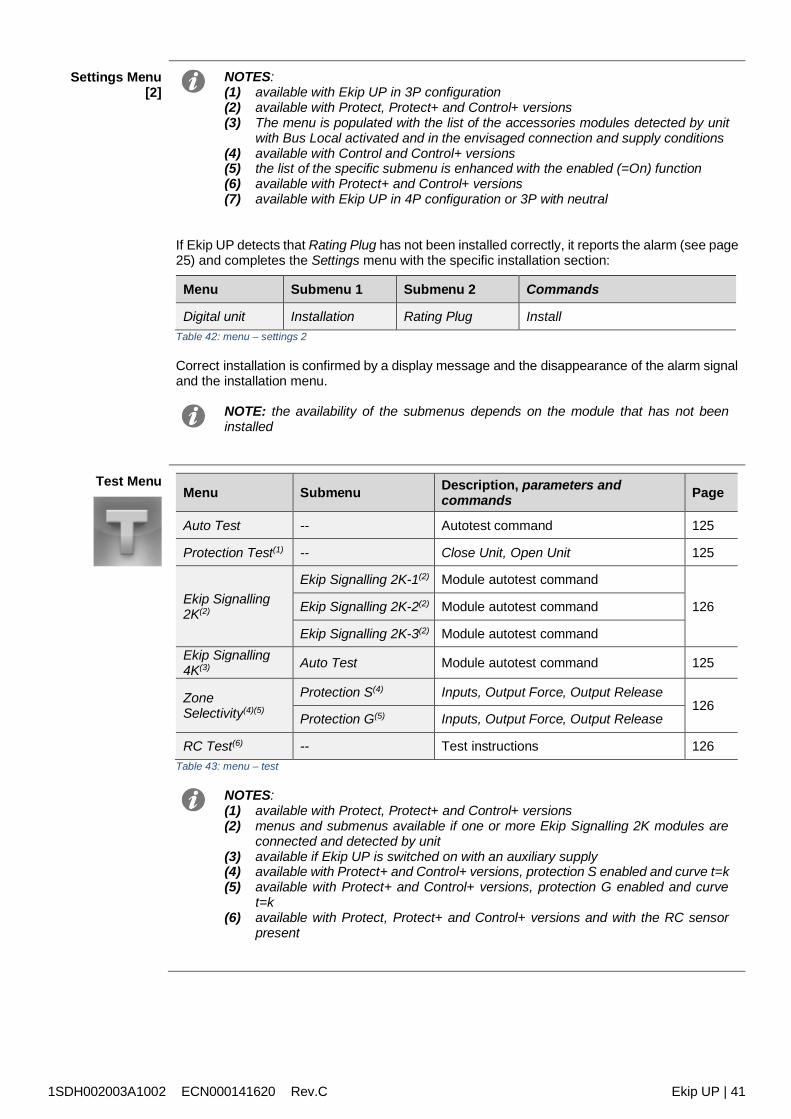
1SDH002003A1002 ECN000141620 Rev.C Ekip UP | 41
Settings Menu[2]
NOTES:(1) available with Ekip UP in 3P configuration(2) available with Protect, Protect+ and Control+ versions(3) The menu is populated with the list of the accessories modules detected by unit
with Bus Local activated and in the envisaged connection and supply conditions(4) available with Control and Control+ versions(5) the list of the specific submenu is enhanced with the enabled (=On) function(6) available with Protect+ and Control+ versions(7) available with Ekip UP in 4P configuration or 3P with neutral
If Ekip UP detects that Rating Plug has not been installed correctly, it reports the alarm (see page25) and completes the Settings menu with the specific installation section:
Menu Submenu 1 Submenu 2 Commands
Digital unit Installation Rating Plug InstallTable 42: menu – settings 2
Correct installation is confirmed by a display message and the disappearance of the alarm signaland the installation menu.
NOTE: the availability of the submenus depends on the module that has not beeninstalled
Test MenuMenu Submenu Description, parameters and
commands Page
Auto Test -- Autotest command 125
Protection Test(1) -- Close Unit, Open Unit 125
Ekip Signalling2K(2)
Ekip Signalling 2K-1(2) Module autotest command
126Ekip Signalling 2K-2(2) Module autotest command
Ekip Signalling 2K-3(2) Module autotest commandEkip Signalling4K(3) Auto Test Module autotest command 125
ZoneSelectivity(4)(5)
Protection S(4) Inputs, Output Force, Output Release126
Protection G(5) Inputs, Output Force, Output Release
RC Test(6) -- Test instructions 126Table 43: menu – test
NOTES:(1) available with Protect, Protect+ and Control+ versions(2) menus and submenus available if one or more Ekip Signalling 2K modules are
connected and detected by unit(3) available if Ekip UP is switched on with an auxiliary supply(4) available with Protect+ and Control+ versions, protection S enabled and curve t=k(5) available with Protect+ and Control+ versions, protection G enabled and curve
t=k(6) available with Protect, Protect+ and Control+ versions and with the RC sensor
present
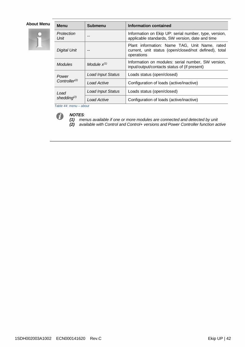
1SDH002003A1002 ECN000141620 Rev.C Ekip UP | 42
About Menu Menu Submenu Information contained
ProtectionUnit -- Information on Ekip UP: serial number, type, version,
applicable standards, SW version, date and time
Digital Unit --Plant information: Name TAG, Unit Name, ratedcurrent, unit status (open/closed/not defined), totaloperations
Modules Module x(1) Information on modules: serial number, SW version,input/output/contacts status of (if present)
PowerController(2)
Load Input Status Loads status (open/closed)
Load Active Configuration of loads (active/inactive)
Loadshedding(2)
Load Input Status Loads status (open/closed)
Load Active Configuration of loads (active/inactive)Table 44: menu – about
NOTES:(1) menus available if one or more modules are connected and detected by unit(2) available with Control and Control+ versions and Power Controller function active
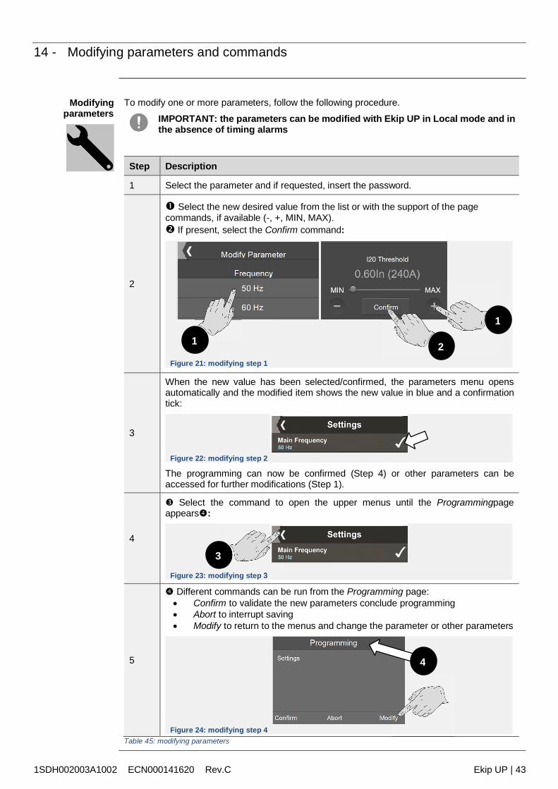
1SDH002003A1002 ECN000141620 Rev.C Ekip UP | 43
14 - Modifying parameters and commands
Modifyingparameters
To modify one or more parameters, follow the following procedure.
IMPORTANT: the parameters can be modified with Ekip UP in Local mode and inthe absence of timing alarms
Step Description
1 Select the parameter and if requested, insert the password.
2
Select the new desired value from the list or with the support of the pagecommands, if available (-, +, MIN, MAX). If present, select the Confirm command:
Figure 21: modifying step 1
3
When the new value has been selected/confirmed, the parameters menu opensautomatically and the modified item shows the new value in blue and a confirmationtick:
Figure 22: modifying step 2
The programming can now be confirmed (Step 4) or other parameters can beaccessed for further modifications (Step 1).
4
Select the command to open the upper menus until the Programmingpageappears:
Figure 23: modifying step 3
5
Different commands can be run from the Programming page: Confirm to validate the new parameters conclude programming Abort to interrupt saving Modify to return to the menus and change the parameter or other parameters
Figure 24: modifying step 4Table 45: modifying parameters
1
2
3
1
4

1SDH002003A1002 ECN000141620 Rev.C Ekip UP | 44
Commands Selecting a command implies running the command immediately or opening an intermediateconfirmation window.
If the command has been run correctly, a confirmation window opens that disappears on its ownfrom the display.The exceptions are certain commands that if selected automatically activate the respective testsequences without any confirmation window: Auto Test (page 125) Ekip Signalling 4K (page 125)
IMPORTANT: the confirmation on the display refers to the running of thecommand, not to the check of the requested operation. The operation must bechecked by the user regardless of the command run: reset parameters, display,open/close contacts
Exceptions Before validating programming or running a command, Ekip UP controls all its parameters tocertify that there is no conflict or error condition.
If the unit detects an error condition on the display and/or the bar shows the details, theprogramming/running of the command is interrupted
WARNING! Cancelling programming impacts all the parameters modified duringthe same session
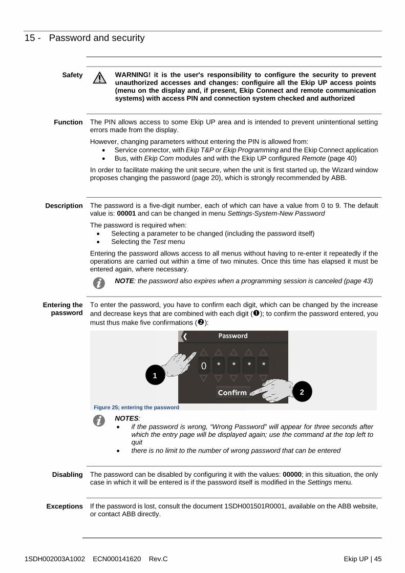
1SDH002003A1002 ECN000141620 Rev.C Ekip UP | 45
15 - Password and security
Safety WARNING! it is the user's responsibility to configure the security to preventunauthorized accesses and changes: configuire all the Ekip UP access points(menu on the display and, if present, Ekip Connect and remote communicationsystems) with access PIN and connection system checked and authorized
Function The PIN allows access to some Ekip UP area and is intended to prevent unintentional settingerrors made from the display.
However, changing parameters without entering the PIN is allowed from: Service connector, with Ekip T&P or Ekip Programming and the Ekip Connect application Bus, with Ekip Com modules and with the Ekip UP configured Remote (page 40)
In order to facilitate making the unit secure, when the unit is first started up, the Wizard windowproposes changing the password (page 20), which is strongly recommended by ABB.
Description The password is a five-digit number, each of which can have a value from 0 to 9. The defaultvalue is: 00001 and can be changed in menu Settings-System-New Password
The password is required when: Selecting a parameter to be changed (including the password itself) Selecting the Test menu
Entering the password allows access to all menus without having to re-enter it repeatedly if theoperations are carried out within a time of two minutes. Once this time has elapsed it must beentered again, where necessary.
NOTE: the password also expires when a programming session is canceled (page 43)
Entering thepassword
To enter the password, you have to confirm each digit, which can be changed by the increaseand decrease keys that are combined with each digit (); to confirm the password entered, youmust thus make five confirmations ():
Figure 25; entering the password
NOTES: if the password is wrong, “Wrong Password” will appear for three seconds after
which the entry page will be displayed again; use the command at the top left toquit
there is no limit to the number of wrong password that can be entered
Disabling The password can be disabled by configuring it with the values: 00000; in this situation, the onlycase in which it will be entered is if the password itself is modified in the Settings menu.
Exceptions If the password is lost, consult the document 1SDH001501R0001, available on the ABB website,or contact ABB directly.
1
2
1SDH002003A1002 ECN000141620 Rev.C Ekip UP | 46
Measurements
16 - Standard measurements
List the standard measurements are:
Name Description Page
Instantaneousmeasurements
Measurements in real time of: current, voltage, frequency,power 47
Events List of events, status changes, alarms, recorded by EkipUP 48
Min-Max-MedMeasurements
History of minimum, maximum and medium currents,voltage and power, recorded at set intervals 48
Peak factor Real time measurement of the peak factor of the currents 49
Power factor Real time measurement of the power factor 49
Energy counters Measurement of active, reactive and apparent energy 49
Maintenance(1) Unit maintenance status 49Table 46: standard menu - list
(1): the Maintenance menu is available after activating the functions in the Settingsmenu (page 40).
The standard measurements packet includes Datalogger and Network Analyzer, as described indedicated chapters starting from page 50.
The Protect, Protect+ and Control+ versions also have the trips history, described on page 60.
The Protect, Protect+ and Control+ versions that have the Ekip Synchrocheck module also havemeasurements of the module and synchronism, which are described from page 178.
1SDH002003A1002 ECN000141620 Rev.C Ekip UP | 47
Instantaneousmeasurements
the following instantaneous measurements are available with Ekip UP:
Measurement Availability Measurementinterval
Normaloperatinginterval
Accuracy ofread value(9)
Phase currents(8)
Pages: HistogramMeasurements (1)
Measuring instruments(1)
Measurements summary(1)
0.03 - 64 In 0.2 - 1.2 In 1%(10)
Internal earth faultcurrent(8) Measurements Page 0.08 - 64 In 0.2 - 1.2 In 2 %(10)
External earth faultcurrent(2) (8) Measurements Page 0.08 - 4 In 0.2 - 1.2 In 2 %(10)
Residual current(2) (8) Measurements Page 2 - 32 A 5 %
Network voltage
Pages: MeasurementsHistograms (1)
Measuring instruments(1)
Measurements summary(1)
5 V - 1.25 Un 100 - 690 V 0.5 %(11)
Phase voltages(3) Measurements Page 5 V - 1.25 Un 50 - 400 V 0.5 %(11)
Network frequency Measurements Menu 30 - 80 Hz(4) f -10 % -f +10 %(5) 0.1 %
Total active, reactiveand apparent power
Pages: MeasurementsSummary ofmeasurementsMeasuring instruments
|Pmin - Pmax|(6)
|0.3 - 1.2 Sn|(7) 2 %(10)
Active, reactive andapparent phasepower(3)
Pages: Measurements |Pmin - Pmax|(6)
|0.3 - 1.2 Pn|(7) 2 %(10)
Table 47: standard menu - performances
NOTES:(1) showed the highest rms value of those measured(2) available by activating the presence of the S.G.R. or RC sensor(3) available in the presence of 4P or 3P systems with neutral (Ekip Measuring menu)(4) available for voltages greater than 30 V (with Un < 277 V) or 60 V (with Un > 277 V)(5) 45-55 Hz with set frequency= 50 Hz; 54-66 Hz with f= 60 Hz(6) Pmin = 0.5 In x 5 V; Pmax= 3 x 16 In x 690 V(7) Sn = In x Un x √3; Pn = In x Un / √3(8) expressed as actual value(9) the accuracy values refer to normal operating intervals according to IEC 61557-12(10) performance refer to entire measurement chain: Ekip UP + current sens type A, B or C(11) without transformers; 0.7 % with class 0.2 external transformers
Special messages
Type of measurement Measurement< min value
Measurement> max value Shown: “_ _ _” (not available) per
Phase currents . . . . > [64 In] Disconnected sensors
Internal earth faultcurrent . . . . > [64 In] Disconnected sensors
External earth faultcurrent . . . . > [4 In sensor] Sensor not activated and/or
disconnected
Residual current . . . . > 32 A Sensor not activated and/ordisconnected
Network voltage andphase voltage . . . . > [Un x 1.25 ] Ekip Measuring not detected
Network frequency 30 Hz 80 Hz Ekip Measuring not present, V < 5 V
Total active, reactiveand apparent power andphase power
. . . . > [Pn x 1.25 ] Disconnected sensors, Ekip Measuringnot present, V < 5 V. I < 0.03 In
Table 48: standard menu – special messages
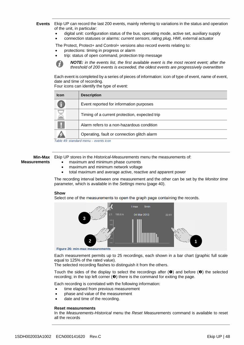
1SDH002003A1002 ECN000141620 Rev.C Ekip UP | 48
Events Ekip UP can record the last 200 events, mainly referring to variations in the status and operationof the unit, in particular: digital unit: configuration status of the bus, operating mode, active set, auxiliary supply connection statuses or alarms: current sensors, rating plug, HMI, external actuator
The Protect, Protect+ and Control+ versions also record events relating to: protections: timing in progress or alarm trip: status of open command, protection trip message
NOTE: in the events list, the first available event is the most recent event; after thethreshold of 200 events is exceeded, the oldest events are progressively overwritten
Each event is completed by a series of pieces of information: icon of type of event, name of event,date and time of recording.Four icons can identify the type of event:
Icon Description
Event reported for information purposes
Timing of a current protection, expected trip
Alarm refers to a non-hazardous condition
Operating, fault or connection glitch alarmTable 49: standard menu – events icon
Min-MaxMeasurements
Ekip UP stores in the Historical-Measurements menu the measurements of: maximum and minimum phase currents maximum and minimum network voltage total maximum and average active, reactive and apparent power
The recording interval between one measurement and the other can be set by the Monitor timeparameter, which is available in the Settings menu (page 40).
ShowSelect one of the measurements to open the graph page containing the records.
Figure 26: min-max measurements
Each measurement permits up to 25 recordings, each shown in a bar chart (graphic full scaleequal to 125% of the rated value).The selected recording flashes to distinguish it from the others.
Touch the sides of the display to select the recordings after () and before () the selectedrecording; in the top left corner () there is the command for exiting the page.
Each recording is correlated with the following information: time elapsed from previous measurement phase and value of the measurement date and time of the recording.
Reset measurementsIn the Measurements-Historical menu the Reset Measurements command is available to resetall the records
3
2 1
1SDH002003A1002 ECN000141620 Rev.C Ekip UP | 49
Peak factor andpower factor
The peak factors are the measurements in real time of the ratio between the peak values theRMS values of the phase currents; the measurement is supported by the protection functionHarmonic dist. (page 96).
The power factor is the measurement in real time of the ratio between total active power and totalapparent power expressed as Cos φ.
Measurement Measurementinterval Accuracy Applicational Notes
Peak factor 0.3 - 6In(currents) 1.5%
Shows “_ _ _” (not available) for out-of-range currents and disconnectedsensors
Power factor 0.5 - 1 2.5%
Shows “_ _ _” (not available) for activeand/or reactive power that is notavailable or is outside permittedranges
Table 50: standard menu – Peak factor and power factor
Energy counters The energy counters are the measurements of the total active, reactive and apparent energy,updated each minute.
Measurement Measurement interval Accuracy
Total active, reactiveand apparent energy
1 kWh - 2 TWh; 1 kVARh - 2 TVARh;1 kVAh - 2 TVAh 2 %
Table 51: standard menu – energy
Reset measurementsIn the Energy menu, the Energy RESET command is available (page 39) to reset the energycounters.
Maintenance The Maintenance function, actrivable on Settings menu (page 40), enables the user to be alertedby a Warning that a year has elapsed since the last maintenance sessions.In the Measurements-Maintenance menu the following are available:
Name Measurement interval
Installation Information on installation date
Last Maintenance date of last maintenance performed
Service RESET maintenance confirmation command: press to update themaintenance date and make the displayed alarm disappear
Table 52: standard menu – maintenance
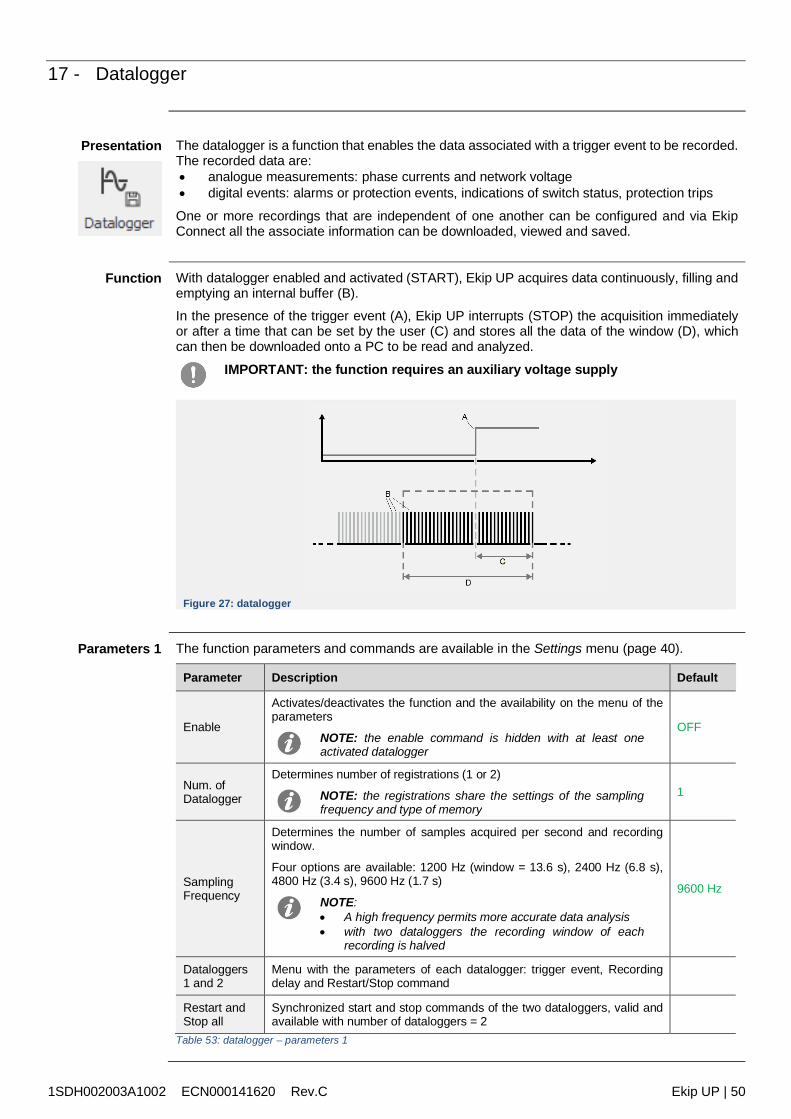
1SDH002003A1002 ECN000141620 Rev.C Ekip UP | 50
17 - Datalogger
Presentation The datalogger is a function that enables the data associated with a trigger event to be recorded.The recorded data are: analogue measurements: phase currents and network voltage digital events: alarms or protection events, indications of switch status, protection trips
One or more recordings that are independent of one another can be configured and via EkipConnect all the associate information can be downloaded, viewed and saved.
Function With datalogger enabled and activated (START), Ekip UP acquires data continuously, filling andemptying an internal buffer (B).In the presence of the trigger event (A), Ekip UP interrupts (STOP) the acquisition immediatelyor after a time that can be set by the user (C) and stores all the data of the window (D), whichcan then be downloaded onto a PC to be read and analyzed.
IMPORTANT: the function requires an auxiliary voltage supply
Figure 27: datalogger
Parameters 1 The function parameters and commands are available in the Settings menu (page 40).
Parameter Description Default
Enable
Activates/deactivates the function and the availability on the menu of theparameters
NOTE: the enable command is hidden with at least oneactivated datalogger
OFF
Num. ofDatalogger
Determines number of registrations (1 or 2)
NOTE: the registrations share the settings of the samplingfrequency and type of memory
1
SamplingFrequency
Determines the number of samples acquired per second and recordingwindow.
Four options are available: 1200 Hz (window = 13.6 s), 2400 Hz (6.8 s),4800 Hz (3.4 s), 9600 Hz (1.7 s)
NOTE: A high frequency permits more accurate data analysis with two dataloggers the recording window of each
recording is halved
9600 Hz
Dataloggers1 and 2
Menu with the parameters of each datalogger: trigger event, Recordingdelay and Restart/Stop command
Restart andStop all
Synchronized start and stop commands of the two dataloggers, valid andavailable with number of dataloggers = 2
Table 53: datalogger – parameters 1
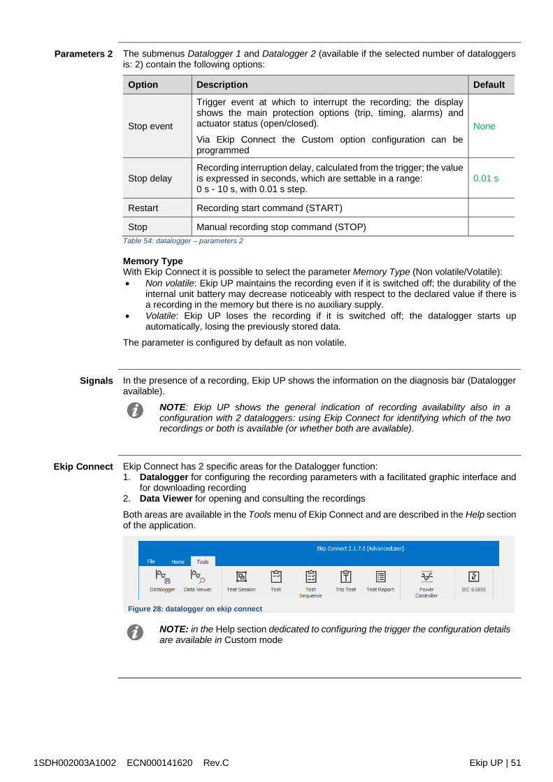
1SDH002003A1002 ECN000141620 Rev.C Ekip UP | 51
Parameters 2 The submenus Datalogger 1 and Datalogger 2 (available if the selected number of dataloggersis: 2) contain the following options:
Option Description Default
Stop event
Trigger event at which to interrupt the recording; the displayshows the main protection options (trip, timing, alarms) andactuator status (open/closed).
Via Ekip Connect the Custom option configuration can beprogrammed
None
Stop delayRecording interruption delay, calculated from the trigger; the valueis expressed in seconds, which are settable in a range:0 s - 10 s, with 0.01 s step.
0.01 s
Restart Recording start command (START)
Stop Manual recording stop command (STOP)Table 54: datalogger – parameters 2
Memory TypeWith Ekip Connect it is possible to select the parameter Memory Type (Non volatile/Volatile): Non volatile: Ekip UP maintains the recording even if it is switched off; the durability of the
internal unit battery may decrease noticeably with respect to the declared value if there isa recording in the memory but there is no auxiliary supply.
Volatile: Ekip UP loses the recording if it is switched off; the datalogger starts upautomatically, losing the previously stored data.
The parameter is configured by default as non volatile.
Signals In the presence of a recording, Ekip UP shows the information on the diagnosis bar (Dataloggeravailable).
NOTE: Ekip UP shows the general indication of recording availability also in aconfiguration with 2 dataloggers: using Ekip Connect for identifying which of the tworecordings or both is available (or whether both are available).
Ekip Connect Ekip Connect has 2 specific areas for the Datalogger function:1. Datalogger for configuring the recording parameters with a facilitated graphic interface and
for downloading recording2. Data Viewer for opening and consulting the recordings
Both areas are available in the Tools menu of Ekip Connect and are described in the Help sectionof the application.
Figure 28: datalogger on ekip connect
NOTE: in the Help section dedicated to configuring the trigger the configuration detailsare available in Custom mode
1SDH002003A1002 ECN000141620 Rev.C Ekip UP | 52
18 - Network Analyzer
Presentation The Network Analyzer function enables voltage and current controls to be set for a long periodto analyze the operation of its plant.
For this purpose, voltage and currents are monitored in order to detect: sequences of voltages (Over, Under, Pos and Neg) unbalance between voltages (Unbalance) short voltage interruptions (V microinterruption) and slow sags (Sag) voltage spikes (Spikes) and slow swells (Swells) harmonic distortion of voltage and currents (THD)
Each monitoring session is associated with control parameters that can be set by the user andwith counters that are increased whenever the set control conditions occur.The function also enables the waveforms and harmonics of the network voltage and of the phasecurrents to be viewed (page 59).
Parameters The configuration parameters of the counters are available in the Settings - Network Analyzermenu (page 40).
In the Settings menu the Monitor time parameter can also be set that defines the period of eachcontrol session.
NOTE: the parameter is the one used for measuring maximum current and voltage
Main Menu
Parameter Description Default
Enable Activates/deactivates the function and the availability on the menuof the parameters OFF
I Harm analysis Activates the harmonic analysis of currents OFF
V Harmc analysis Activates the harmonic analysis of voltage OFF
V Threshold LowControl threshold of counter Under V Th
The value is expressed as a percentage of the rated voltage Un,which can be set between 75 % - 95 % Un, with 5% step
85 % Un
V Threshold HighControl threshold of counter Over V Th
The value is expressed as a percentage of the rated voltage Un,which can be set between 105, 110, 115 % Un
110 % Un
Unbalance Th
Alarm threshold for the Unbalance counter.
The value is expressed as a percentage of the rated voltage Un,which can be set between 2 % - 10 % Un, with 1 % step
NOTE: 0 % =symmetrical and balanced system
3 % Un
V microinterr. ThControl threshold of the V microinterr. counter
The value is expressed as a percentage of the rated voltage Un,which can be set between 10 % - 95 % Un, with 5% step
95 % Un
V Spike ThresholdControl threshold of the Spike counter
The value is expressed as a percentage of Un, which is settable ina range 105 % - 125 % Un, with 5 % step
105 % Un
Sags Menu with the voltage sags control parameters
Swells Menu with the harmonic voltage swells control
HarmonicThe submenu becomes available by enabling the harmonic currentand/or voltage analysis and enables the harmonics controlparameters to be configured.
Table 55: network analyzer – main menu
1SDH002003A1002 ECN000141620 Rev.C Ekip UP | 53
Parameters [2] Sags MenuAll thresholds are expressed as a percentage of the rated voltage Un, which can be set between10 % - 95 % Un, with 5% stepAll times are given in seconds, which can be set between 0.04 s - 60 s with variable step.
Parameter Description Default
V sag Th Short Control threshold of Sags Short counter 10 % Un
V sag dur Short Minimum duration of sag below Short threshold to validatecount of Sags Short counter 0.8 s
V sag Th Middle Control threshold of Sags Middle counter 45 % Un
V sag dur Middle Minimum duration of sag below Middle threshold to validatecount of Sags Middle counter 0.8 s
V sag Th Long Control threshold of Sags Long counter 95 % Un
V sag dur Long Minimum duration of sag below Long threshold to validatecount of Sags Long counter 0.8 s
Table 56: network analyzer – sag
NOTE: Ekip UP accepts modifications of the parameters if the following constraints arefollowed: V sag dur Long V sag dur Middle V sag dur Short
Swells MenuAll thresholds are expressed as a percentage of the rated voltage Un, which can be set between105 % - 125 % Un, with 5% stepAll times are given in seconds, which can be set between 0.04 s - 60 s with variable step.
Parameter Description Default
V swell Th Short Control threshold of Swell Short counter 125 % Un
V swell dur Short Minimum duration of swell above Short threshold to validatecount of Swell Short counter 0.8 s
V swell Th Long Control threshold of the Swells Long counter 105 % Un
V swell dur Long Minimum duration of swell above Long threshold to validatecount of Swells Long counter 0.8 s
Table 57: network analyzer – swell
NOTE: Ekip UP accepts modifications of the parameters if the following constraints arefollowed: V swell dur Long V swell dur Short
Harmonics (Current and Voltage)All the percentages are expressed as a percentage value and can be set in a 5 % - 20 % range(total THD) or 3 % - 10 % (single harmonics) with 1 % step.
Menu Parameter Description Default
CurrentTHD Threshold Control threshold of the THD voltage counter 5 %
Single thharmonic Control threshold for the single voltage harmonics 5 %
VoltageTHD Threshold Control threshold of the THD current counter 5 %
Single thharmonic
Control threshold for the single current harmonicscounters 5 %
Table 58: network analyzer – THD
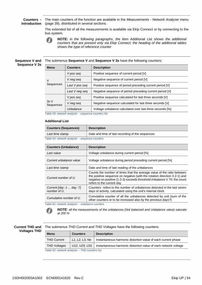
1SDH002003A1002 ECN000141620 Rev.C Ekip UP | 54
Counters -Introduction
The main counters of the function are available in the Measurements - Network Analyzer menu(page 39), distributed in several sections.
The extended list of all the measurements is available via Ekip Connect or by connecting to thebus system.
NOTE: in the following paragraphs, the item Additional List shows the additionalcounters that are present only via Ekip Connect; the heading of the additional tablesshows the type of reference counter
Sequence V andSequence V 3s
The submenus Sequence V and Sequence V 3s have the following counters:
Menu Counters Description
VSequences
V pos seq Positive sequence of current period [V]
V neg seq Negative sequence of current period [V]
Last V pos seq Positive sequence of period preceding current period [V]
Last V neg seq Negative sequence of period preceding current period [V]
3s VSequences
V pos seq Positive sequence calculated for last three seconds [V]
V neg seq Negative sequence calculated for last three seconds [V]
Unbalance Voltage unbalance calculated over last three seconds [%]Table 59: network analyzer – sequence counters list
Additional List
Counters (Sequences) Description
Last time stamp Date and time of last recording of the sequencesTable 60: network analyzer – sequence counters
Counters (Unbalance) Description
Last value Voltage unbalance during current period [%]
Current unbalance value Voltage unbalance during period preceding current period [%]
Last time stamp Date and time of last reading of the unbalances
Current number of U.
Counts the number of times that the average value of the ratio betweenthe positive sequence on negative (with the rotation direction 3-2-1) andnegative on positive (1-2-3) exceeds threshold Imbalance V Th; the countrefers to the current day
Current [day -1 ... day -7]number of U.
Counters refers to the number of unbalances detected in the last sevendays of activity, calculated using the unit's internal clock
Cumulative number of U. Cumulative counter of all the unbalances detected by unit (sum of theother counters or to be increased also by the previous days?)
Table 61: network analyzer – unbalance counters
NOTE: all the measurements of the unbalances (Not balanced and Unbalance value) saturateat 200 %
Current THD andVoltages THD
The submenus THD Current and THD Voltages have the following counters:
Menu Counters Description
THD Current L1, L2, L3, Ne Instantaneous harmonic distortion value of each current phase
THD Voltages U12, U23, U31 Instantaneous harmonic distortion value of each network voltageTable 62: network analyzer – THD counters list
1SDH002003A1002 ECN000141620 Rev.C Ekip UP | 55
Over V Th andUnder V Th
In the submenus Counters - Day-1 and Counters -Cumulative are available referring to themeasurements of the sequences:
Counters Description
Over V Th
Counts the number of times that the average value of the positive sequence (in therotation direction of the phases: 1-2-3) or negative sequence (in the set rotationdirection of the phases: 3-2-1) exceeds threshold V Threshold High. The count refersto the interval of the reference menu (previous day or cumulative)
Under V Th
Counts the number of times that the average value of the positive sequence (in therotation direction of the phases: 1-2-3) or negative sequence (in the set rotationdirection of the phases: 3-2-1) falls below threshold V Threshold Low. The count refersto the interval of the reference menu (previous day or cumulative)
Table 63: network analyzer – over and under counters
Additional ListCounters (Over Voltage) Description
Last time stamp Date and time of last recording of the Over V Th counter
Last value Value of last swell above Over V Th [V] threshold
Current number of O. Over V Th [V] count for current day
Current [day -2 ... day -7]number of O.
Over V Th [V] count of last seven days of activity, calculated using theunit's internal clock
Table 64: network analyzer – over voltage counters
Counters (Under Voltage) Description
Last time stamp Date and time of last recording of the Over V Th counter
Last value Value of last sag below Over V Th threshold [V]
Current number of O. Over V Th [V] count for current day
Current [day -2 ... day -7]number of O.
Over V Th [V] count of last seven days of activity, calculated using theunit's internal clock
Table 65: network analyzer – under voltage counters
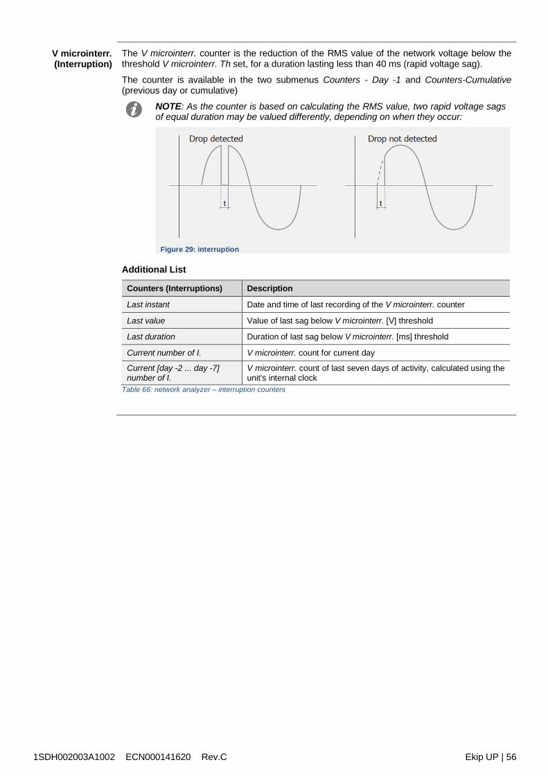
1SDH002003A1002 ECN000141620 Rev.C Ekip UP | 56
V microinterr.(Interruption)
The V microinterr. counter is the reduction of the RMS value of the network voltage below thethreshold V microinterr. Th set, for a duration lasting less than 40 ms (rapid voltage sag).
The counter is available in the two submenus Counters - Day -1 and Counters-Cumulative(previous day or cumulative)
NOTE: As the counter is based on calculating the RMS value, two rapid voltage sagsof equal duration may be valued differently, depending on when they occur:
Figure 29: interruption
Additional List
Counters (Interruptions) Description
Last instant Date and time of last recording of the V microinterr. counter
Last value Value of last sag below V microinterr. [V] threshold
Last duration Duration of last sag below V microinterr. [ms] threshold
Current number of I. V microinterr. count for current day
Current [day -2 ... day -7]number of I.
V microinterr. count of last seven days of activity, calculated using theunit's internal clock
Table 66: network analyzer – interruption counters
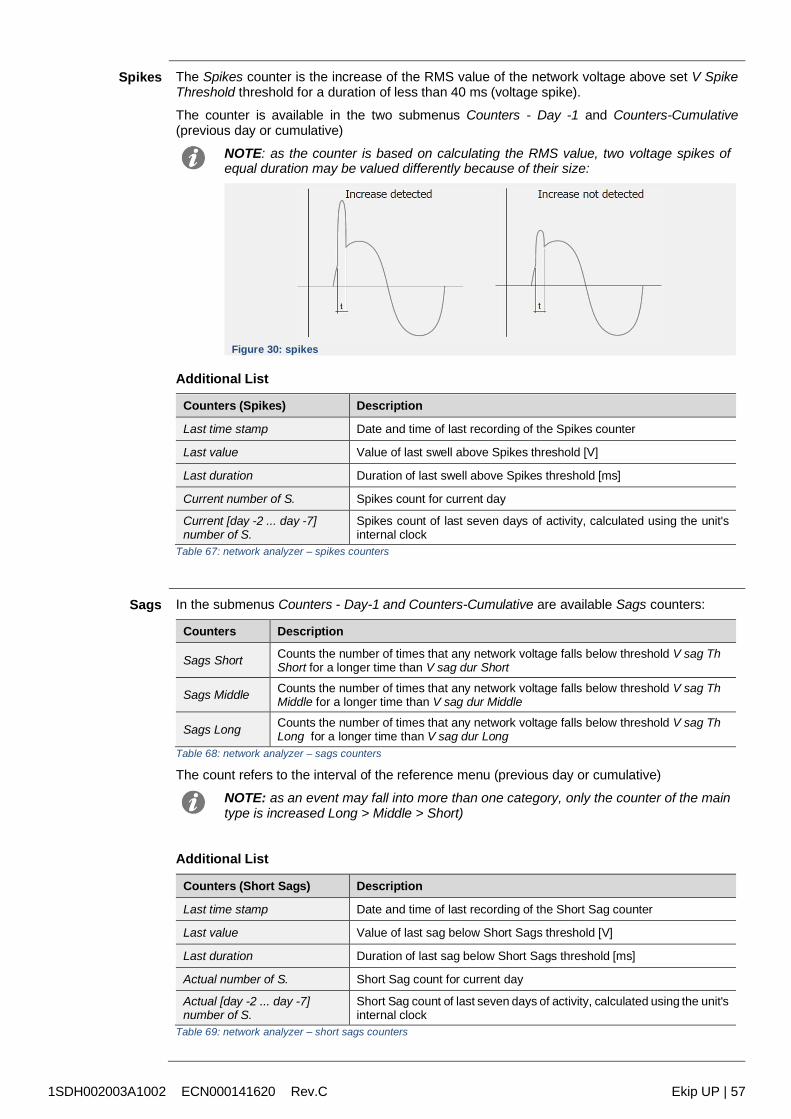
1SDH002003A1002 ECN000141620 Rev.C Ekip UP | 57
Spikes The Spikes counter is the increase of the RMS value of the network voltage above set V SpikeThreshold threshold for a duration of less than 40 ms (voltage spike).
The counter is available in the two submenus Counters - Day -1 and Counters-Cumulative(previous day or cumulative)
NOTE: as the counter is based on calculating the RMS value, two voltage spikes ofequal duration may be valued differently because of their size:
Figure 30: spikes
Additional List
Counters (Spikes) Description
Last time stamp Date and time of last recording of the Spikes counter
Last value Value of last swell above Spikes threshold [V]
Last duration Duration of last swell above Spikes threshold [ms]
Current number of S. Spikes count for current day
Current [day -2 ... day -7]number of S.
Spikes count of last seven days of activity, calculated using the unit'sinternal clock
Table 67: network analyzer – spikes counters
Sags In the submenus Counters - Day-1 and Counters-Cumulative are available Sags counters:
Counters Description
Sags Short Counts the number of times that any network voltage falls below threshold V sag ThShort for a longer time than V sag dur Short
Sags Middle Counts the number of times that any network voltage falls below threshold V sag ThMiddle for a longer time than V sag dur Middle
Sags Long Counts the number of times that any network voltage falls below threshold V sag ThLong for a longer time than V sag dur Long
Table 68: network analyzer – sags counters
The count refers to the interval of the reference menu (previous day or cumulative)
NOTE: as an event may fall into more than one category, only the counter of the maintype is increased Long > Middle > Short)
Additional List
Counters (Short Sags) Description
Last time stamp Date and time of last recording of the Short Sag counter
Last value Value of last sag below Short Sags threshold [V]
Last duration Duration of last sag below Short Sags threshold [ms]
Actual number of S. Short Sag count for current day
Actual [day -2 ... day -7]number of S.
Short Sag count of last seven days of activity, calculated using the unit'sinternal clock
Table 69: network analyzer – short sags counters
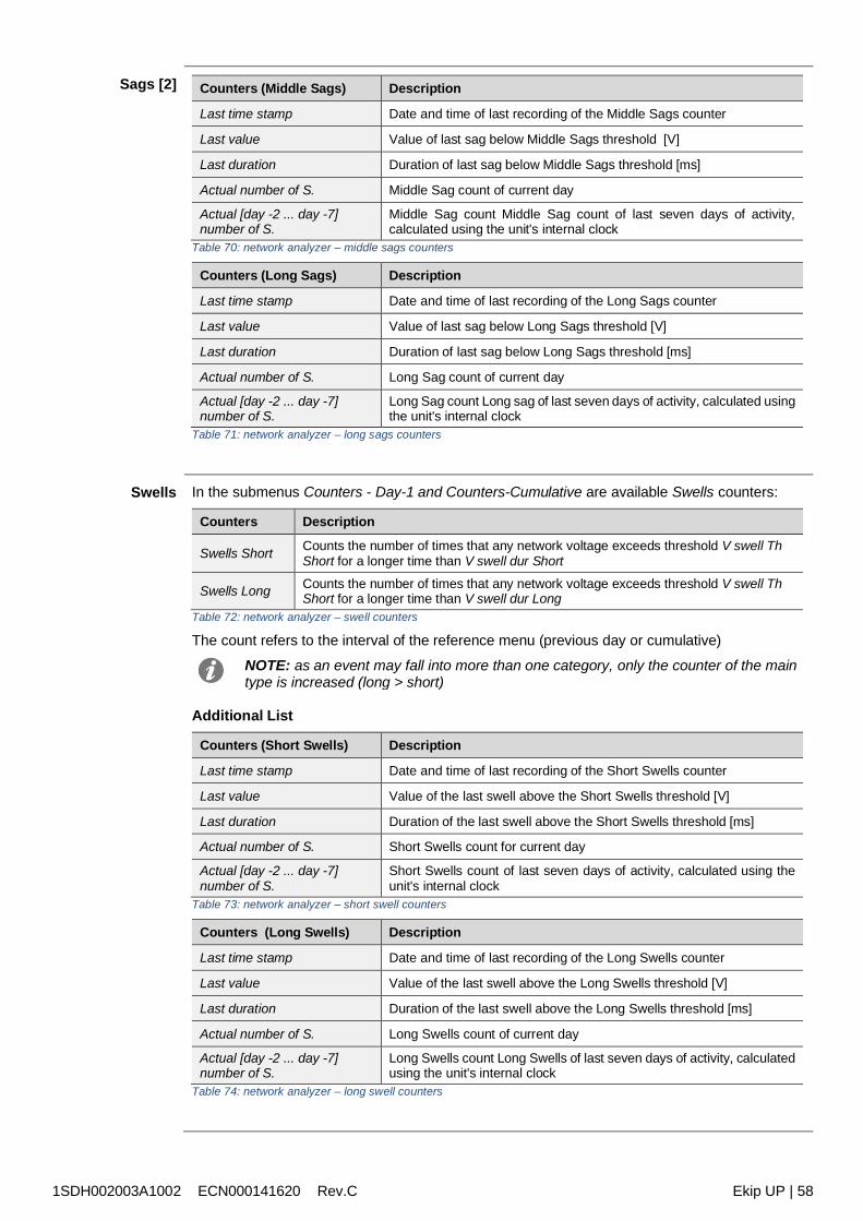
1SDH002003A1002 ECN000141620 Rev.C Ekip UP | 58
Sags [2] Counters (Middle Sags) Description
Last time stamp Date and time of last recording of the Middle Sags counter
Last value Value of last sag below Middle Sags threshold [V]
Last duration Duration of last sag below Middle Sags threshold [ms]
Actual number of S. Middle Sag count of current day
Actual [day -2 ... day -7]number of S.
Middle Sag count Middle Sag count of last seven days of activity,calculated using the unit's internal clock
Table 70: network analyzer – middle sags counters
Counters (Long Sags) Description
Last time stamp Date and time of last recording of the Long Sags counter
Last value Value of last sag below Long Sags threshold [V]
Last duration Duration of last sag below Long Sags threshold [ms]
Actual number of S. Long Sag count of current day
Actual [day -2 ... day -7]number of S.
Long Sag count Long sag of last seven days of activity, calculated usingthe unit's internal clock
Table 71: network analyzer – long sags counters
Swells In the submenus Counters - Day-1 and Counters-Cumulative are available Swells counters:
Counters Description
Swells Short Counts the number of times that any network voltage exceeds threshold V swell ThShort for a longer time than V swell dur Short
Swells Long Counts the number of times that any network voltage exceeds threshold V swell ThShort for a longer time than V swell dur Long
Table 72: network analyzer – swell counters
The count refers to the interval of the reference menu (previous day or cumulative)
NOTE: as an event may fall into more than one category, only the counter of the maintype is increased (long > short)
Additional List
Counters (Short Swells) Description
Last time stamp Date and time of last recording of the Short Swells counter
Last value Value of the last swell above the Short Swells threshold [V]
Last duration Duration of the last swell above the Short Swells threshold [ms]
Actual number of S. Short Swells count for current day
Actual [day -2 ... day -7]number of S.
Short Swells count of last seven days of activity, calculated using theunit's internal clock
Table 73: network analyzer – short swell counters
Counters (Long Swells) Description
Last time stamp Date and time of last recording of the Long Swells counter
Last value Value of the last swell above the Long Swells threshold [V]
Last duration Duration of the last swell above the Long Swells threshold [ms]
Actual number of S. Long Swells count of current day
Actual [day -2 ... day -7]number of S.
Long Swells count Long Swells of last seven days of activity, calculatedusing the unit's internal clock
Table 74: network analyzer – long swell counters
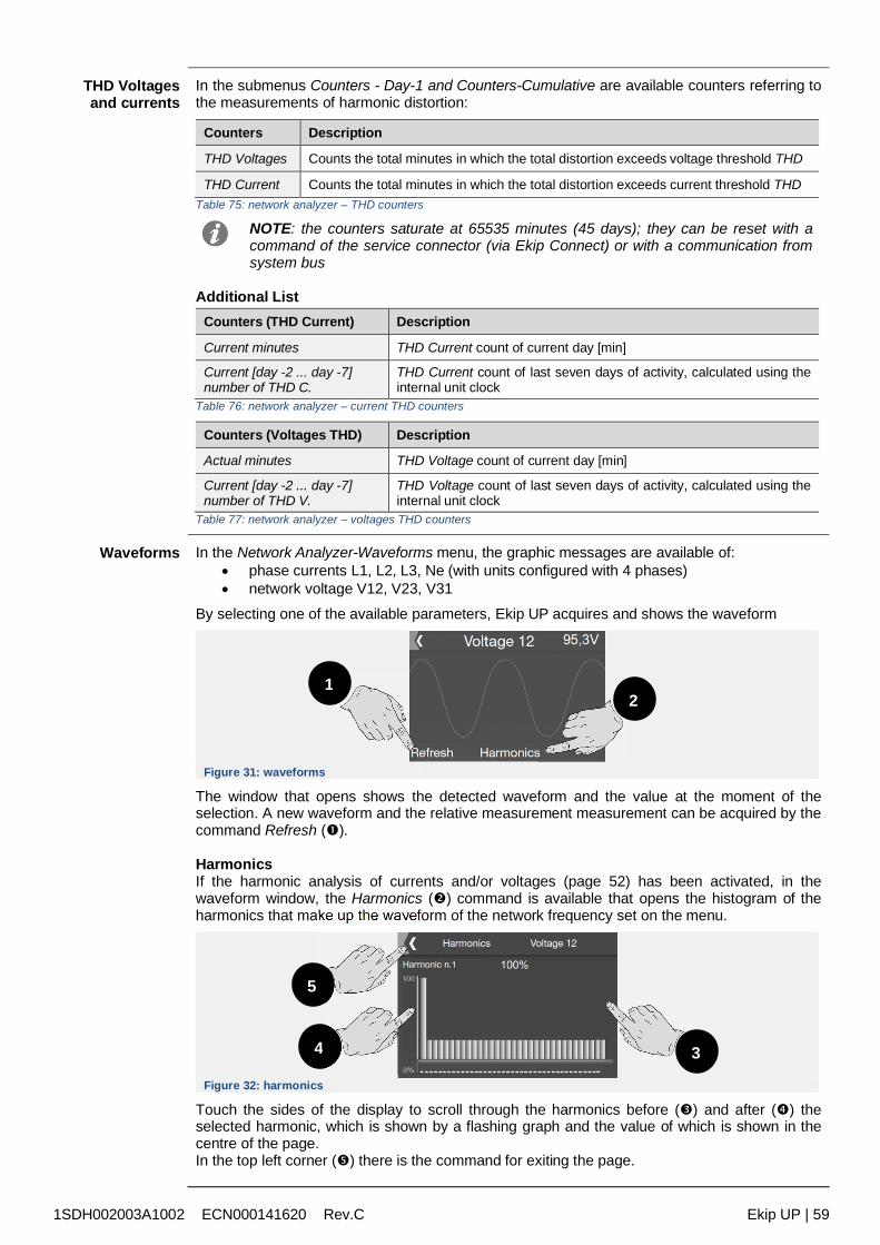
1SDH002003A1002 ECN000141620 Rev.C Ekip UP | 59
THD Voltagesand currents
In the submenus Counters - Day-1 and Counters-Cumulative are available counters referring tothe measurements of harmonic distortion:
Counters Description
THD Voltages Counts the total minutes in which the total distortion exceeds voltage threshold THD
THD Current Counts the total minutes in which the total distortion exceeds current threshold THDTable 75: network analyzer – THD counters
NOTE: the counters saturate at 65535 minutes (45 days); they can be reset with acommand of the service connector (via Ekip Connect) or with a communication fromsystem bus
Additional ListCounters (THD Current) Description
Current minutes THD Current count of current day [min]
Current [day -2 ... day -7]number of THD C.
THD Current count of last seven days of activity, calculated using theinternal unit clock
Table 76: network analyzer – current THD counters
Counters (Voltages THD) Description
Actual minutes THD Voltage count of current day [min]
Current [day -2 ... day -7]number of THD V.
THD Voltage count of last seven days of activity, calculated using theinternal unit clock
Table 77: network analyzer – voltages THD counters
Waveforms In the Network Analyzer-Waveforms menu, the graphic messages are available of: phase currents L1, L2, L3, Ne (with units configured with 4 phases) network voltage V12, V23, V31
By selecting one of the available parameters, Ekip UP acquires and shows the waveform
Figure 31: waveforms
The window that opens shows the detected waveform and the value at the moment of theselection. A new waveform and the relative measurement measurement can be acquired by thecommand Refresh ().
HarmonicsIf the harmonic analysis of currents and/or voltages (page 52) has been activated, in thewaveform window, the Harmonics () command is available that opens the histogram of theharmonics that make up the waveform of the network frequency set on the menu.
Figure 32: harmonics
Touch the sides of the display to scroll through the harmonics before () and after () theselected harmonic, which is shown by a flashing graph and the value of which is shown in thecentre of the page.In the top left corner () there is the command for exiting the page.
12
5
4 3
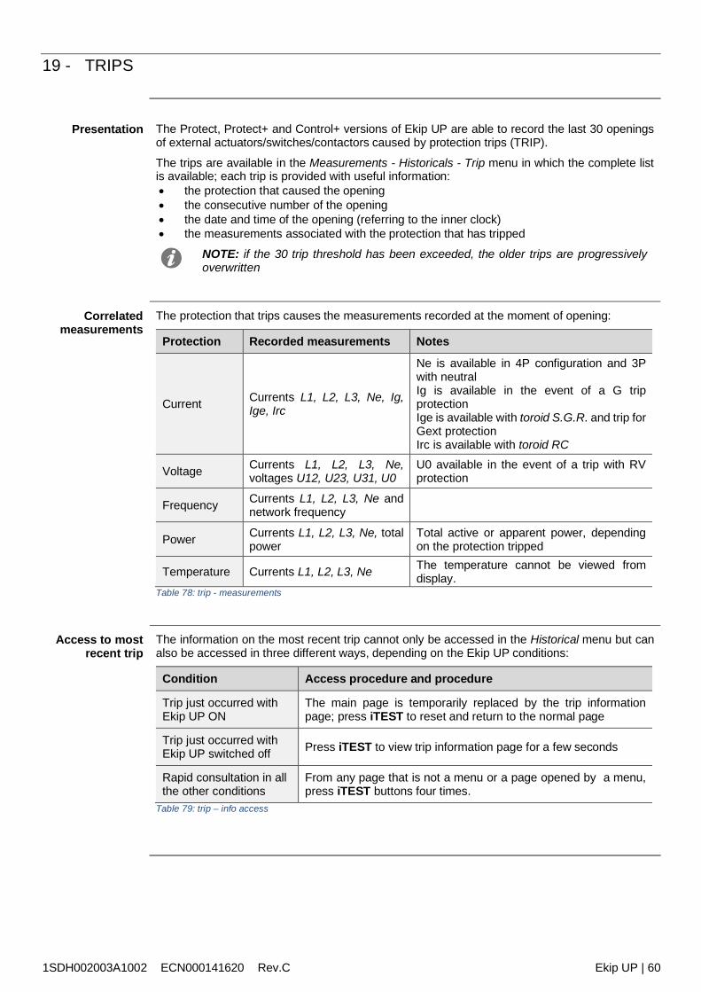
1SDH002003A1002 ECN000141620 Rev.C Ekip UP | 60
19 - TRIPS
Presentation The Protect, Protect+ and Control+ versions of Ekip UP are able to record the last 30 openingsof external actuators/switches/contactors caused by protection trips (TRIP).
The trips are available in the Measurements - Historicals - Trip menu in which the complete listis available; each trip is provided with useful information: the protection that caused the opening the consecutive number of the opening the date and time of the opening (referring to the inner clock) the measurements associated with the protection that has tripped
NOTE: if the 30 trip threshold has been exceeded, the older trips are progressivelyoverwritten
Correlatedmeasurements
The protection that trips causes the measurements recorded at the moment of opening:
Protection Recorded measurements Notes
Current Currents L1, L2, L3, Ne, Ig,Ige, Irc
Ne is available in 4P configuration and 3Pwith neutralIg is available in the event of a G tripprotectionIge is available with toroid S.G.R. and trip forGext protectionIrc is available with toroid RC
Voltage Currents L1, L2, L3, Ne,voltages U12, U23, U31, U0
U0 available in the event of a trip with RVprotection
Frequency Currents L1, L2, L3, Ne andnetwork frequency
Power Currents L1, L2, L3, Ne, totalpower
Total active or apparent power, dependingon the protection tripped
Temperature Currents L1, L2, L3, Ne The temperature cannot be viewed fromdisplay.
Table 78: trip - measurements
Access to mostrecent trip
The information on the most recent trip cannot only be accessed in the Historical menu but canalso be accessed in three different ways, depending on the Ekip UP conditions:
Condition Access procedure and procedure
Trip just occurred withEkip UP ON
The main page is temporarily replaced by the trip informationpage; press iTEST to reset and return to the normal page
Trip just occurred withEkip UP switched off Press iTEST to view trip information page for a few seconds
Rapid consultation in allthe other conditions
From any page that is not a menu or a page opened by a menu,press iTEST buttons four times.
Table 79: trip – info access
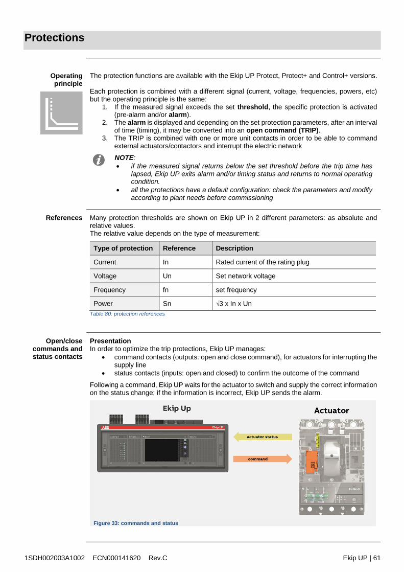
1SDH002003A1002 ECN000141620 Rev.C Ekip UP | 61
Protections
Operatingprinciple
The protection functions are available with the Ekip UP Protect, Protect+ and Control+ versions.
Each protection is combined with a different signal (current, voltage, frequencies, powers, etc)but the operating principle is the same:
1. If the measured signal exceeds the set threshold, the specific protection is activated(pre-alarm and/or alarm).
2. The alarm is displayed and depending on the set protection parameters, after an intervalof time (timing), it may be converted into an open command (TRIP).
3. The TRIP is combined with one or more unit contacts in order to be able to commandexternal actuators/contactors and interrupt the electric network
NOTE: if the measured signal returns below the set threshold before the trip time has
lapsed, Ekip UP exits alarm and/or timing status and returns to normal operatingcondition.
all the protections have a default configuration: check the parameters and modifyaccording to plant needs before commissioning
References Many protection thresholds are shown on Ekip UP in 2 different parameters: as absolute andrelative values.The relative value depends on the type of measurement:
Type of protection Reference Description
Current In Rated current of the rating plug
Voltage Un Set network voltage
Frequency fn set frequency
Power Sn √3 x In x UnTable 80: protection references
Open/closecommands andstatus contacts
PresentationIn order to optimize the trip protections, Ekip UP manages:
command contacts (outputs: open and close command), for actuators for interrupting thesupply line
status contacts (inputs: open and closed) to confirm the outcome of the command
Following a command, Ekip UP waits for the actuator to switch and supply the correct informationon the status change; if the information is incorrect, Ekip UP sends the alarm.
Figure 33: commands and status
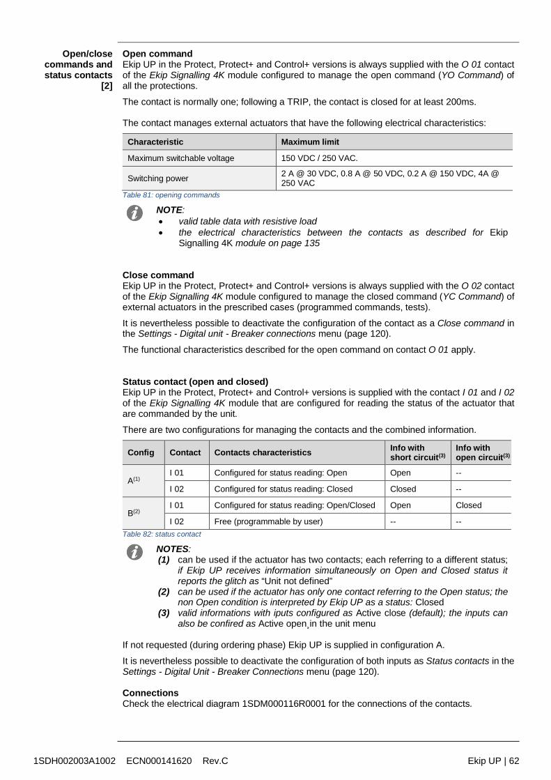
1SDH002003A1002 ECN000141620 Rev.C Ekip UP | 62
Open/closecommands andstatus contacts
[2]
Open commandEkip UP in the Protect, Protect+ and Control+ versions is always supplied with the O 01 contactof the Ekip Signalling 4K module configured to manage the open command (YO Command) ofall the protections.
The contact is normally one; following a TRIP, the contact is closed for at least 200ms.
The contact manages external actuators that have the following electrical characteristics:
Characteristic Maximum limit
Maximum switchable voltage 150 VDC / 250 VAC.
Switching power 2 A @ 30 VDC, 0.8 A @ 50 VDC, 0.2 A @ 150 VDC, 4A @250 VAC
Table 81: opening commands
NOTE: valid table data with resistive load the electrical characteristics between the contacts as described for Ekip
Signalling 4K module on page 135
Close commandEkip UP in the Protect, Protect+ and Control+ versions is always supplied with the O 02 contactof the Ekip Signalling 4K module configured to manage the closed command (YC Command) ofexternal actuators in the prescribed cases (programmed commands, tests).
It is nevertheless possible to deactivate the configuration of the contact as a Close command inthe Settings - Digital unit - Breaker connections menu (page 120).
The functional characteristics described for the open command on contact O 01 apply.
Status contact (open and closed)Ekip UP in the Protect, Protect+ and Control+ versions is supplied with the contact I 01 and I 02of the Ekip Signalling 4K module that are configured for reading the status of the actuator thatare commanded by the unit.
There are two configurations for managing the contacts and the combined information.
Config Contact Contacts characteristics Info withshort circuit(3)
Info withopen circuit(3)
A(1)I 01 Configured for status reading: Open Open --
I 02 Configured for status reading: Closed Closed --
B(2)I 01 Configured for status reading: Open/Closed Open Closed
I 02 Free (programmable by user) -- --Table 82: status contact
NOTES:(1) can be used if the actuator has two contacts; each referring to a different status;
if Ekip UP receives information simultaneously on Open and Closed status itreports the glitch as “Unit not defined”
(2) can be used if the actuator has only one contact referring to the Open status; thenon Open condition is interpreted by Ekip UP as a status: Closed
(3) valid informations with iputs configured as Active close (default); the inputs canalso be confired as Active open¸in the unit menu
If not requested (during ordering phase) Ekip UP is supplied in configuration A.
It is nevertheless possible to deactivate the configuration of both inputs as Status contacts in theSettings - Digital Unit - Breaker Connections menu (page 120).
ConnectionsCheck the electrical diagram 1SDM000116R0001 for the connections of the contacts.
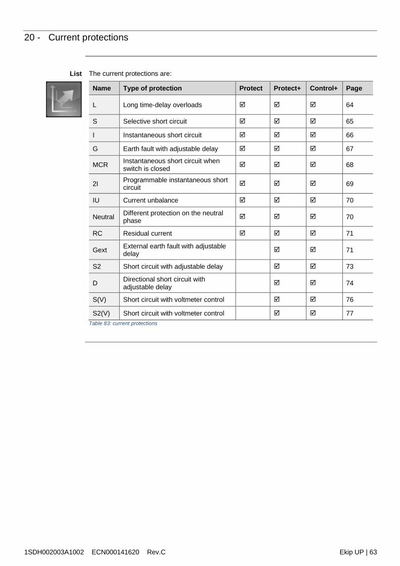
1SDH002003A1002 ECN000141620 Rev.C Ekip UP | 63
20 - Current protections
List The current protections are:
Name Type of protection Protect Protect+ Control+ Page
L Long time-delay overloads 64
S Selective short circuit 65
I Instantaneous short circuit 66
G Earth fault with adjustable delay 67
MCR Instantaneous short circuit whenswitch is closed 68
2I Programmable instantaneous shortcircuit 69
IU Current unbalance 70
Neutral Different protection on the neutralphase 70
RC Residual current 71
Gext External earth fault with adjustabledelay 71
S2 Short circuit with adjustable delay 73
D Directional short circuit withadjustable delay 74
S(V) Short circuit with voltmeter control 76
S2(V) Short circuit with voltmeter control 77Table 83: current protections
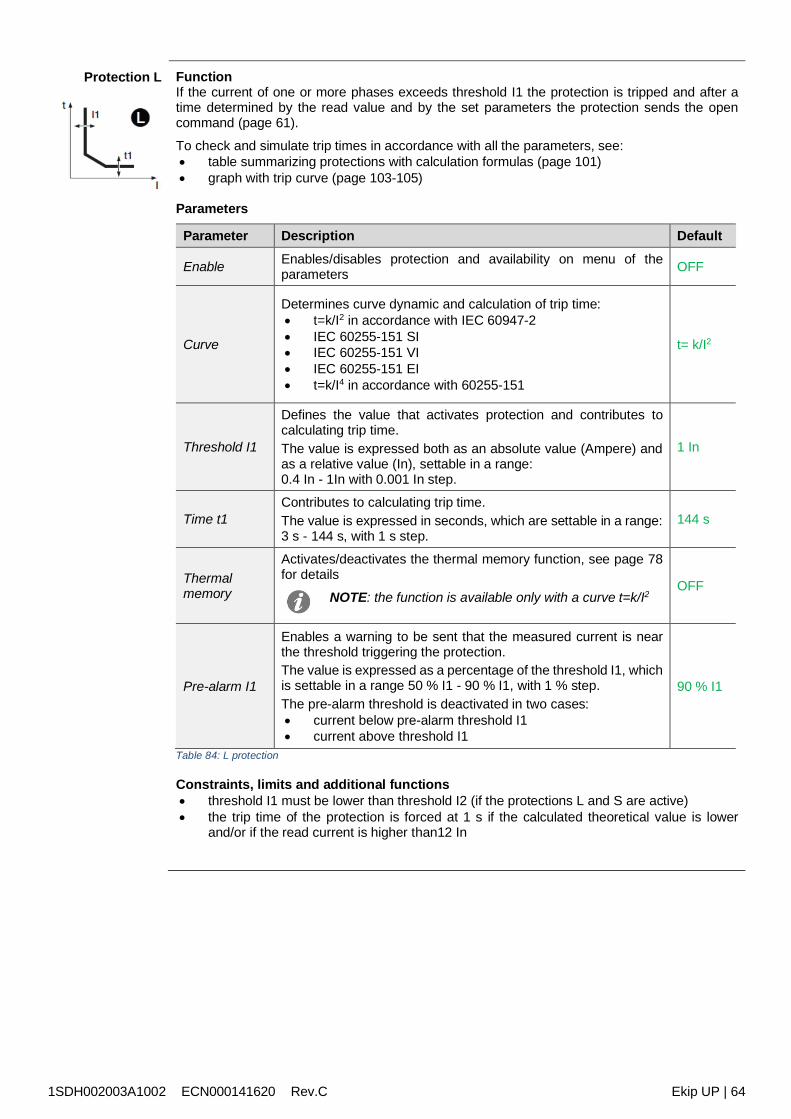
1SDH002003A1002 ECN000141620 Rev.C Ekip UP | 64
Protection L FunctionIf the current of one or more phases exceeds threshold I1 the protection is tripped and after atime determined by the read value and by the set parameters the protection sends the opencommand (page 61).
To check and simulate trip times in accordance with all the parameters, see: table summarizing protections with calculation formulas (page 101) graph with trip curve (page 103-105)
Parameters
Parameter Description Default
Enable Enables/disables protection and availability on menu of theparameters OFF
Curve
Determines curve dynamic and calculation of trip time: t=k/I2 in accordance with IEC 60947-2 IEC 60255-151 SI IEC 60255-151 VI IEC 60255-151 EI t=k/I4 in accordance with 60255-151
t= k/I2
Threshold I1
Defines the value that activates protection and contributes tocalculating trip time.The value is expressed both as an absolute value (Ampere) andas a relative value (In), settable in a range:0.4 In - 1In with 0.001 In step.
1 In
Time t1Contributes to calculating trip time.The value is expressed in seconds, which are settable in a range:3 s - 144 s, with 1 s step.
144 s
Thermalmemory
Activates/deactivates the thermal memory function, see page 78for details
NOTE: the function is available only with a curve t=k/I2OFF
Pre-alarm I1
Enables a warning to be sent that the measured current is nearthe threshold triggering the protection.The value is expressed as a percentage of the threshold I1, whichis settable in a range 50 % I1 - 90 % I1, with 1 % step.The pre-alarm threshold is deactivated in two cases: current below pre-alarm threshold I1 current above threshold I1
90 % I1
Table 84: L protection
Constraints, limits and additional functions threshold I1 must be lower than threshold I2 (if the protections L and S are active) the trip time of the protection is forced at 1 s if the calculated theoretical value is lower
and/or if the read current is higher than12 In
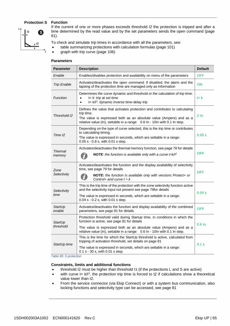
1SDH002003A1002 ECN000141620 Rev.C Ekip UP | 65
Protection S FunctionIf the current of one or more phases exceeds threshold I2 the protection is tripped and after atime determined by the read value and by the set parameters sends the open command (page61).
To check and simulate trip times in accordance with all the parameters, see: table summarizing protections with calculation formulas (page 101) graph with trip curve (page 106)
Parameters
Parameter Description Default
Enable Enables/disables protection and availability on menu of the parameters OFF
Trip Enable Activates/deactivates the open command: if disabled, the alarm and thelapsing of the protection time are managed only as information ON
FunctionDetermines the curve dynamic and threshold or the calculation of trip time: t= k: trip at set time t= k/I2: dynamic inverse time-delay trip
t= k
Threshold I2
Defines the value that activates protection and contributes to calculatingtrip time.The value is expressed both as an absolute value (Ampere) and as arelative value (In), settable in a range: 0.6 In - 10In with 0.1 In step.
2 In
Time t2
Depending on the type of curve selected, this is the trip time or contributesto calculating timing.The value is expressed in seconds, which are settable in a range:0.05 s - 0.8 s, with 0.01 s step.
0.05 s
Thermalmemory
Activates/deactivates the thermal memory function, see page 78 for details
NOTE: the function is available only with a curve t=k/I2 OFF
ZoneSelectivity
Activates/deactivates the function and the display availability of selectivitytime, see page 79 for details
NOTE: the function is available only with versions Protect+ orControl+ and curve t = k
OFF
Selectivitytime
This is the trip time of the protection with the zone selectivity function activeand the selectivity input not present see page 79for details
The value is expressed in seconds, which are settable in a range:0.04 s - 0.2 s, with 0.01 s step.
0.04 s
StartUpenable
Activates/deactivates the function and display availability of the combinedparameters, see page 81 for details OFF
StartUpthreshold
Protection threshold valid during Startup time, in conditions in which thefunction is active, see page 81 for details
The value is expressed both as an absolute value (Ampere) and as arelative value (In), settable in a range: 0.6 In - 10In with 0.1 In step.
0.6 In
StartUp time
This is the time for which the StartUp threshold is active, calculated fromtripping of activation threshold, set details on page 81
The value is expressed in seconds, which are settable in a range:0.1 s - 30 s, with 0.01 s step.
0.1 s
Table 85: S protection
Constraints, limits and additional functions threshold I2 must be higher than threshold I1 (if the protections L and S are active) with curve t= k/I2, the protection trip time is forced to t2 if calculations show a theoretical
value lower than t2. From the service connector (via Ekip Connect) or with a system bus communication, also
locking functions and selectivity type can be accessed, see page 81
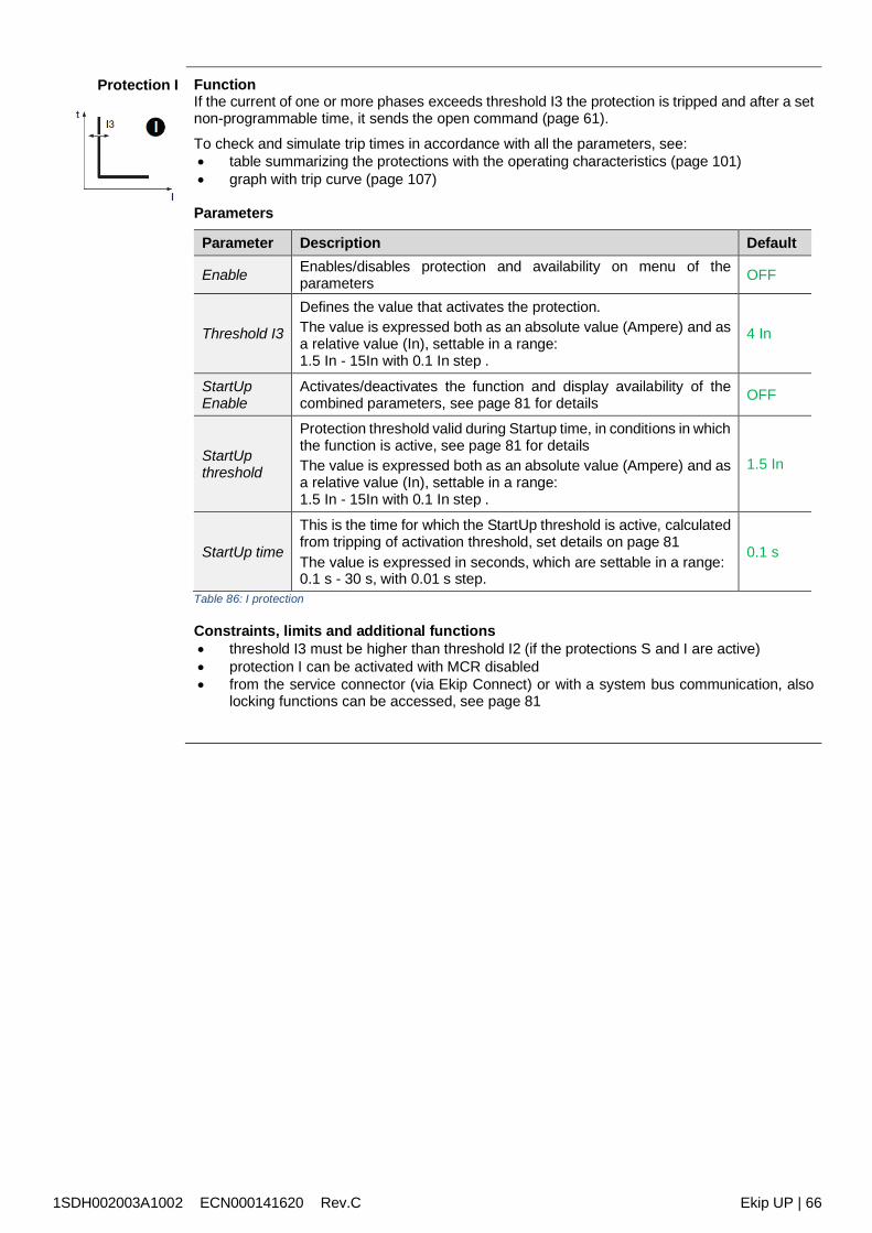
1SDH002003A1002 ECN000141620 Rev.C Ekip UP | 66
Protection I FunctionIf the current of one or more phases exceeds threshold I3 the protection is tripped and after a setnon-programmable time, it sends the open command (page 61).
To check and simulate trip times in accordance with all the parameters, see: table summarizing the protections with the operating characteristics (page 101) graph with trip curve (page 107)
Parameters
Parameter Description Default
Enable Enables/disables protection and availability on menu of theparameters OFF
Threshold I3
Defines the value that activates the protection.The value is expressed both as an absolute value (Ampere) and asa relative value (In), settable in a range:1.5 In - 15In with 0.1 In step .
4 In
StartUpEnable
Activates/deactivates the function and display availability of thecombined parameters, see page 81 for details OFF
StartUpthreshold
Protection threshold valid during Startup time, in conditions in whichthe function is active, see page 81 for detailsThe value is expressed both as an absolute value (Ampere) and asa relative value (In), settable in a range:1.5 In - 15In with 0.1 In step .
1.5 In
StartUp time
This is the time for which the StartUp threshold is active, calculatedfrom tripping of activation threshold, set details on page 81The value is expressed in seconds, which are settable in a range:0.1 s - 30 s, with 0.01 s step.
0.1 s
Table 86: I protection
Constraints, limits and additional functions threshold I3 must be higher than threshold I2 (if the protections S and I are active) protection I can be activated with MCR disabled from the service connector (via Ekip Connect) or with a system bus communication, also
locking functions can be accessed, see page 81
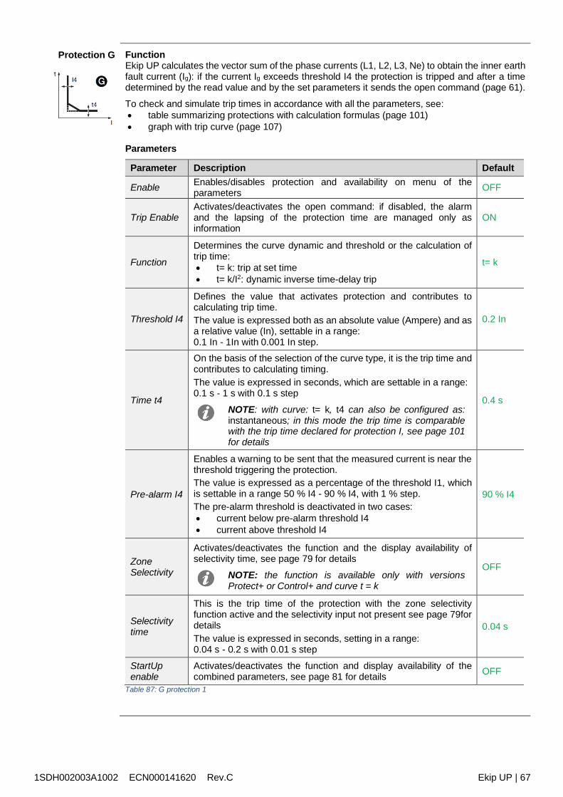
1SDH002003A1002 ECN000141620 Rev.C Ekip UP | 67
Protection G FunctionEkip UP calculates the vector sum of the phase currents (L1, L2, L3, Ne) to obtain the inner earthfault current (Ig): if the current Ig exceeds threshold I4 the protection is tripped and after a timedetermined by the read value and by the set parameters it sends the open command (page 61).
To check and simulate trip times in accordance with all the parameters, see: table summarizing protections with calculation formulas (page 101) graph with trip curve (page 107)
Parameters
Parameter Description Default
Enable Enables/disables protection and availability on menu of theparameters OFF
Trip EnableActivates/deactivates the open command: if disabled, the alarmand the lapsing of the protection time are managed only asinformation
ON
Function
Determines the curve dynamic and threshold or the calculation oftrip time: t= k: trip at set time t= k/I2: dynamic inverse time-delay trip
t= k
Threshold I4
Defines the value that activates protection and contributes tocalculating trip time.The value is expressed both as an absolute value (Ampere) and asa relative value (In), settable in a range:0.1 In - 1In with 0.001 In step.
0.2 In
Time t4
On the basis of the selection of the curve type, it is the trip time andcontributes to calculating timing.The value is expressed in seconds, which are settable in a range:0.1 s - 1 s with 0.1 s step
NOTE: with curve: t= k, t4 can also be configured as:instantaneous; in this mode the trip time is comparablewith the trip time declared for protection I, see page 101for details
0.4 s
Pre-alarm I4
Enables a warning to be sent that the measured current is near thethreshold triggering the protection.The value is expressed as a percentage of the threshold I1, whichis settable in a range 50 % I4 - 90 % I4, with 1 % step.The pre-alarm threshold is deactivated in two cases: current below pre-alarm threshold I4 current above threshold I4
90 % I4
ZoneSelectivity
Activates/deactivates the function and the display availability ofselectivity time, see page 79 for details
NOTE: the function is available only with versionsProtect+ or Control+ and curve t = k
OFF
Selectivitytime
This is the trip time of the protection with the zone selectivityfunction active and the selectivity input not present see page 79fordetailsThe value is expressed in seconds, setting in a range:0.04 s - 0.2 s with 0.01 s step
0.04 s
StartUpenable
Activates/deactivates the function and display availability of thecombined parameters, see page 81 for details OFF
Table 87: G protection 1
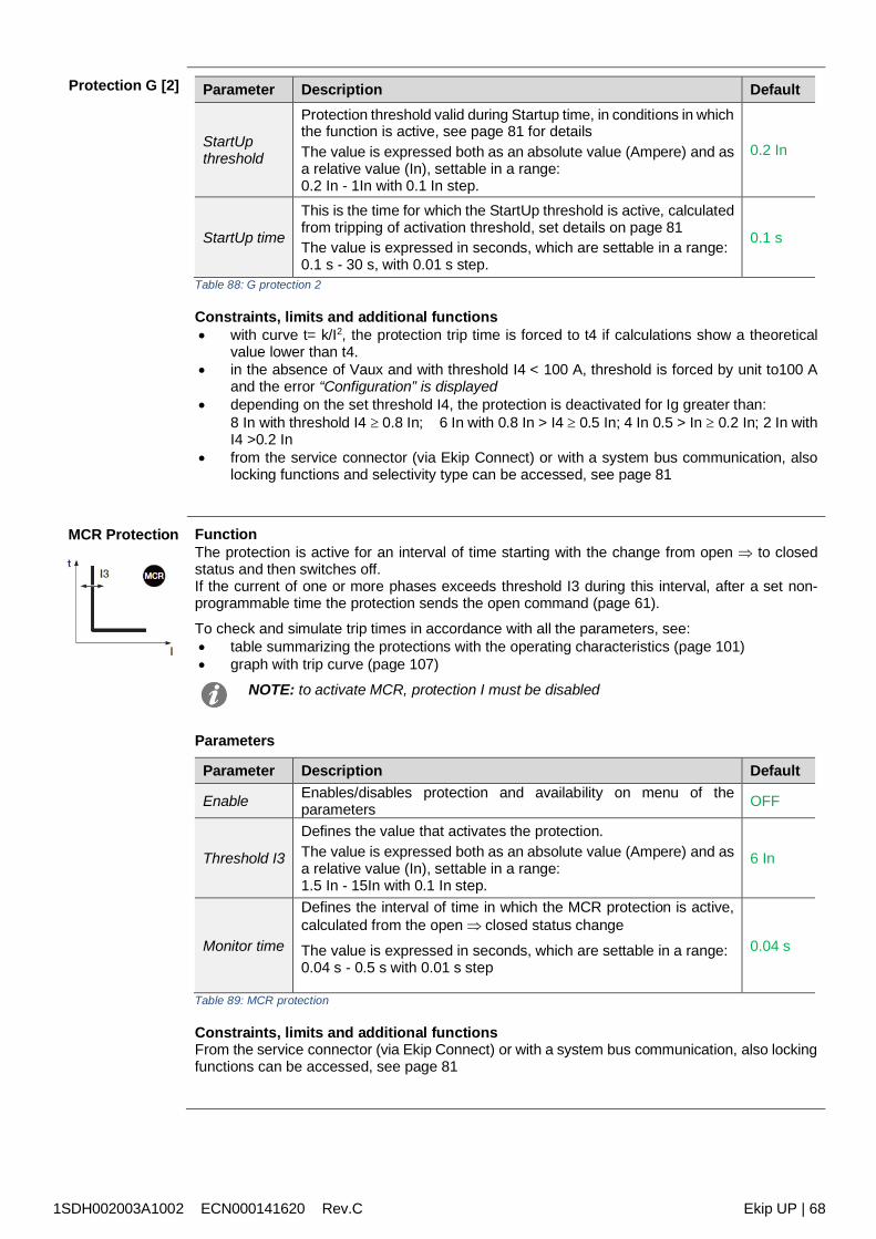
1SDH002003A1002 ECN000141620 Rev.C Ekip UP | 68
Protection G [2] Parameter Description Default
StartUpthreshold
Protection threshold valid during Startup time, in conditions in whichthe function is active, see page 81 for detailsThe value is expressed both as an absolute value (Ampere) and asa relative value (In), settable in a range:0.2 In - 1In with 0.1 In step.
0.2 In
StartUp time
This is the time for which the StartUp threshold is active, calculatedfrom tripping of activation threshold, set details on page 81The value is expressed in seconds, which are settable in a range:0.1 s - 30 s, with 0.01 s step.
0.1 s
Table 88: G protection 2
Constraints, limits and additional functions with curve t= k/I2, the protection trip time is forced to t4 if calculations show a theoretical
value lower than t4. in the absence of Vaux and with threshold I4 < 100 A, threshold is forced by unit to100 A
and the error “Configuration” is displayed depending on the set threshold I4, the protection is deactivated for Ig greater than:
8 In with threshold I4 0.8 In; 6 In with 0.8 In > I4 0.5 In; 4 In 0.5 > In 0.2 In; 2 In withI4 >0.2 In
from the service connector (via Ekip Connect) or with a system bus communication, alsolocking functions and selectivity type can be accessed, see page 81
MCR Protection FunctionThe protection is active for an interval of time starting with the change from open to closedstatus and then switches off.If the current of one or more phases exceeds threshold I3 during this interval, after a set non-programmable time the protection sends the open command (page 61).
To check and simulate trip times in accordance with all the parameters, see: table summarizing the protections with the operating characteristics (page 101) graph with trip curve (page 107)
NOTE: to activate MCR, protection I must be disabled
Parameters
Parameter Description Default
Enable Enables/disables protection and availability on menu of theparameters OFF
Threshold I3
Defines the value that activates the protection.The value is expressed both as an absolute value (Ampere) and asa relative value (In), settable in a range:1.5 In - 15In with 0.1 In step.
6 In
Monitor time
Defines the interval of time in which the MCR protection is active,calculated from the open closed status change
The value is expressed in seconds, which are settable in a range:0.04 s - 0.5 s with 0.01 s step
0.04 s
Table 89: MCR protection
Constraints, limits and additional functionsFrom the service connector (via Ekip Connect) or with a system bus communication, also lockingfunctions can be accessed, see page 81
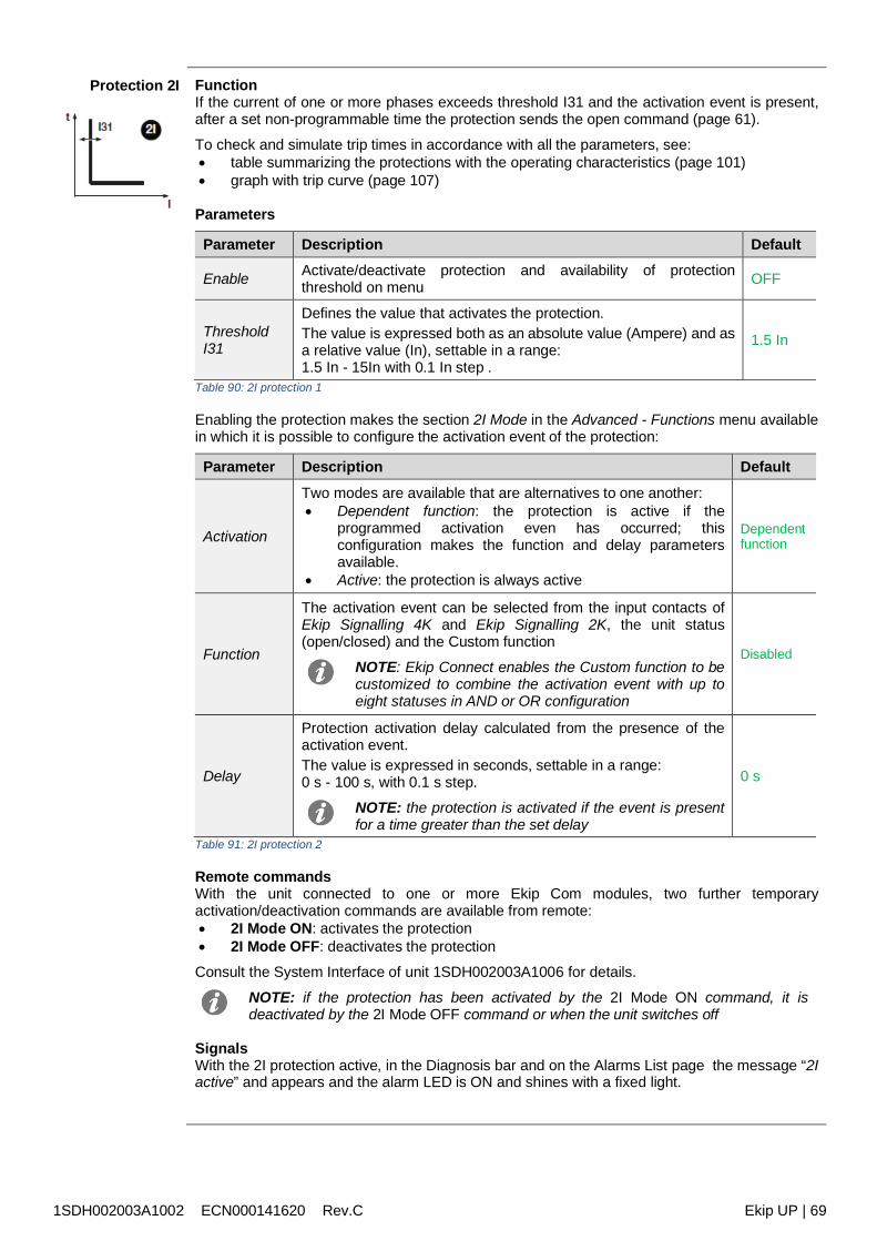
1SDH002003A1002 ECN000141620 Rev.C Ekip UP | 69
Protection 2I FunctionIf the current of one or more phases exceeds threshold I31 and the activation event is present,after a set non-programmable time the protection sends the open command (page 61).
To check and simulate trip times in accordance with all the parameters, see: table summarizing the protections with the operating characteristics (page 101) graph with trip curve (page 107)
Parameters
Parameter Description Default
Enable Activate/deactivate protection and availability of protectionthreshold on menu OFF
ThresholdI31
Defines the value that activates the protection.The value is expressed both as an absolute value (Ampere) and asa relative value (In), settable in a range:1.5 In - 15In with 0.1 In step .
1.5 In
Table 90: 2I protection 1
Enabling the protection makes the section 2I Mode in the Advanced - Functions menu availablein which it is possible to configure the activation event of the protection:
Parameter Description Default
Activation
Two modes are available that are alternatives to one another: Dependent function: the protection is active if the
programmed activation even has occurred; thisconfiguration makes the function and delay parametersavailable.
Active: the protection is always active
Dependentfunction
Function
The activation event can be selected from the input contacts ofEkip Signalling 4K and Ekip Signalling 2K, the unit status(open/closed) and the Custom function
NOTE: Ekip Connect enables the Custom function to becustomized to combine the activation event with up toeight statuses in AND or OR configuration
Disabled
Delay
Protection activation delay calculated from the presence of theactivation event.The value is expressed in seconds, settable in a range:0 s - 100 s, with 0.1 s step.
NOTE: the protection is activated if the event is presentfor a time greater than the set delay
0 s
Table 91: 2I protection 2
Remote commandsWith the unit connected to one or more Ekip Com modules, two further temporaryactivation/deactivation commands are available from remote: 2I Mode ON: activates the protection 2I Mode OFF: deactivates the protection
Consult the System Interface of unit 1SDH002003A1006 for details.
NOTE: if the protection has been activated by the 2I Mode ON command, it isdeactivated by the 2I Mode OFF command or when the unit switches off
SignalsWith the 2I protection active, in the Diagnosis bar and on the Alarms List page the message “2Iactive” and appears and the alarm LED is ON and shines with a fixed light.
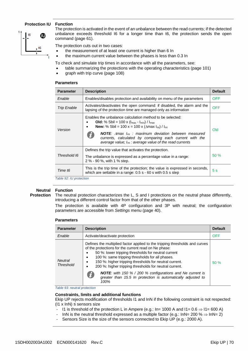
1SDH002003A1002 ECN000141620 Rev.C Ekip UP | 70
Protection IU FunctionThe protection is activated in the event of an unbalance between the read currents; if the detectedunbalance exceeds threshold I6 for a longer time than t6, the protection sends the opencommand (page 61).
The protection cuts out in two cases: the measurement of at least one current is higher than 6 In the maximum current value between the phases is less than 0.3 In
To check and simulate trip times in accordance with all the parameters, see: table summarizing the protections with the operating characteristics (page 101) graph with trip curve (page 108)
Parameters
Parameter Description Default
Enable Enables/disables protection and availability on menu of the parameters OFF
Trip Enable Activates/deactivates the open command: if disabled, the alarm and thelapsing of the protection time are managed only as information OFF
Version
Enables the unbalance calculation method to be selected: Old: % Sbil = 100 x (Imax - Imin) / Imax New: % Sbil = 100 x = 100 x (max Imi) / Imi
NOTE: max Imi : maximum deviation between measuredcurrents, calculated by comparing each current with theaverage value; Imi : average value of the read currents
Old
Threshold I6Defines the trip value that activates the protection.
The unbalance is expressed as a percentage value in a range:2 % - 90 %, with 1 % step.
50 %
Time t6 This is the trip time of the protection; the value is expressed in seconds,which are settable in a range: 0.5 s - 60 s with 0.5 s step 5 s
Table 92: IU protection
NeutralProtection
FunctionThe neutral protection characterizes the L, S and I protections on the neutral phase differently,introducing a different control factor from that of the other phases.The protection is available with 4P configuration and 3P with neutral; the configurationparameters are accessible from Settings menu (page 40).
Parameters
Parameter Description Default
Enable Activate/deactivate protection OFF
NeutralThreshold
Defines the multiplied factor applied to the tripping thresholds and curvesof the protections for the current read on Ne phase: 50 %: lower tripping thresholds for neutral current 100 %: same tripping thresholds for all phases. 150 %: higher tripping thresholds for neutral current. 200 %: higher tripping thresholds for neutral current.
NOTE: with 150 % / 200 % configurations and Ne current isgreater than 15.5 In protection is automatically adjusted to100%
50 %
Table 93: neutral protection
Constraints, limits and additional functionsEkip UP rejects modification of thresholds I1 and InN if the following constraint is not respected:(I1 x InN) ≤ sensors size- I1 is threshold of the protection L in Ampere (e.g.: In= 1000 A and I1= 0.6 I1= 600 A)- InN is the neutral threshold expressed as a multiple factor (e.g.: InN= 200 % InN= 2)- Sensors Size is the size of the sensors connected to Ekip UP (e.g.: 2000 A).
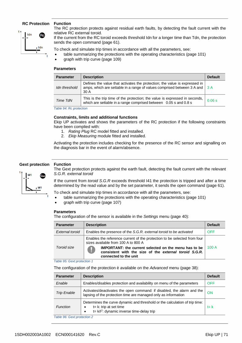
1SDH002003A1002 ECN000141620 Rev.C Ekip UP | 71
RC Protection FunctionThe RC protection protects against residual earth faults, by detecting the fault current with therelative RC external toroid.If the current from the RC toroid exceeds threshold Idn for a longer time than Tdn, the protectionsends the open command (page 61).To check and simulate trip times in accordance with all the parameters, see: table summarizing the protections with the operating characteristics (page 101) graph with trip curve (page 109)
Parameters
Parameter Description Default
Idn thresholdDefines the value that activates the protection; the value is expressed inamps, which are settable in a range of values comprised between 3 A and30 A
3 A
Time TdN This is the trip time of the protection; the value is expressed in seconds,which are settable in a range comprised between 0.05 s and 0.8 s 0.06 s
Table 94: Rc protection
Constraints, limits and additional functionsEkip UP activates and shows the parameters of the RC protection if the following constraintshave been complied with:
1. Rating Plug RC model fitted and installed.2. Ekip Measuring module fitted and installed.
Activating the protection includes checking for the presence of the RC sensor and signalling onthe diagnosis bar in the event of alarm/absence.
Gext protection FunctionThe Gext protection protects against the earth fault, detecting the fault current with the relevantS.G.R. external toroid
If the current from toroid S.G.R exceeds threshold I41 the protection is tripped and after a timedetermined by the read value and by the set parameter, it sends the open command (page 61).To check and simulate trip times in accordance with all the parameters, see: table summarizing the protections with the operating characteristics (page 101) graph with trip curve (page 107)
ParametersThe configuration of the sensor is available in the Settings menu (page 40):
Parameter Description Default
External toroid Enables the presence of the S.G.R. external toroid to be activated OFF
Toroid size
Enables the reference current of the protection to be selected from foursizes available from 100 A to 800 A
IMPORTANT: the current selected on the menu has to beconsistent with the size of the external toroid S.G.R.connected to the unit
100 A
Table 95: Gext protection 1
The configuration of the protection è available on the Advanced menu (page 38):
Parameter Description Default
Enable Enables/disables protection and availability on menu of the parameters OFF
Trip Enable Activates/deactivates the open command: if disabled, the alarm and thelapsing of the protection time are managed only as information ON
FunctionDetermines the curve dynamic and threshold or the calculation of trip time: t= k: trip at set time t= k/I2: dynamic inverse time-delay trip
t= k
Table 96: Gext protection 2
1SDH002003A1002 ECN000141620 Rev.C Ekip UP | 72
Gext protection[2]
Parameter Description Default
ThresholdI41
Defines the value that activates protection and contributes tocalculating trip time.The value is expressed both as an absolute value (Ampere) and asa relative value (In, referring to the size of the outer toroid), settablein a range: 0.1 In - 1In with 0.001 In step.
0.2 In
Time t41
On the basis of the selection of the curve type, it is the trip time andcontributes to calculating timing.The value is expressed in seconds, settable in a range:0.1 s - 1 s, with 0.05 s step.
0.4 s
Pre-alarmI41
Enables a warning to be sent that the measured current is near thethreshold triggering the protection.The value is expressed as a percentage of the threshold I1, whichis settable in a range 50 % I41 - 90 % I41, with 1 % step.The pre-alarm threshold is deactivated in two cases: current below the prealarm threshold I41 current above threshold I41
90 %I41
ZoneSelectivity
Activates/deactivates the function and the display availability ofselectivity time, see page 79 for details
NOTE: the function is available only with versions Protect+
or Control+ and curve t = k in the presence of both G and Gext active
selectivity, the inlet and output are shared with anOR function: it is also sufficient for just one of thetwo to be activated to stimulate inputs and outputs
OFF
Selectivitytime
This is the trip time of the protection with the zone selectivityfunction active and the selectivity input not present see page 79 fordetailsThe value is expressed in seconds, settable in a range:0.04 s - 0.2 s, with 0.01 s step.
0.04 s
StartUpenable
Activates/deactivates the function and display availability of thecombined parameters, see page 81 for details OFF
StartUpthreshold
Protection threshold valid during Startup time, in conditions in whichthe function is active, see page 81 for detailsThe value is expressed both as an absolute value (Ampere) and asa relative value (In), settable in a range: 0.2 In - 1In with 0.1 In step
0.2 In
StartUp time
This is the time for which the StartUp threshold is active, calculatedfrom tripping of activation threshold, set details on page 81The value is expressed in seconds, settable in a range:0.1 s - 30 s, with 0.01 s step.
0.1 s
Table 97: Gext protection 3
Constraints, limits and additional functions with curve t= k/I2, the protection trip time is forced to t41 if calculations show a theoretical
value lower than t41. Ekip UP activates and shows the parameters of the Gext protection if the presence of the
S.G.R sensor has been enabled on the Settings menu (page 40); the activation of theprotection includes checking for the presence of the S.G.R and the indication on thediagnosis bar in the event of alarm/absence
the protection is inhibited automatically by the unit if the absence of the S.G.R. toroid hasbeen detected.
from the service connector (via Ekip Connect) or with a system bus communication, alsolocking functions and selectivity type can be accessed, see page 81
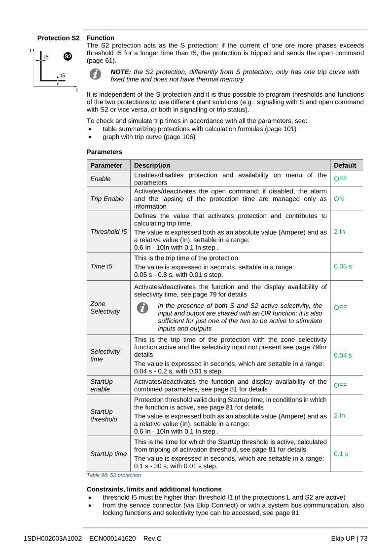
1SDH002003A1002 ECN000141620 Rev.C Ekip UP | 73
Protection S2 FunctionThe S2 protection acts as the S protection: if the current of one ore more phases exceedsthreshold I5 for a longer time than t5, the protection is tripped and sends the open command(page 61).
NOTE: the S2 protection, differently from S protection, only has one trip curve withfixed time and does not have thermal memory
It is independent of the S protection and it is thus possible to program thresholds and functionsof the two protections to use different plant solutions (e.g.: signalling with S and open commandwith S2 or vice versa, or both in signalling or trip status).
To check and simulate trip times in accordance with all the parameters, see: table summarizing protections with calculation formulas (page 101) graph with trip curve (page 106)
Parameters
Parameter Description Default
Enable Enables/disables protection and availability on menu of theparameters OFF
Trip EnableActivates/deactivates the open command: if disabled, the alarmand the lapsing of the protection time are managed only asinformation
ON
Threshold I5
Defines the value that activates protection and contributes tocalculating trip time.The value is expressed both as an absolute value (Ampere) and asa relative value (In), settable in a range:0.6 In - 10In with 0.1 In step .
2 In
Time t5This is the trip time of the protection.The value is expressed in seconds, settable in a range:0.05 s - 0.8 s, with 0.01 s step.
0.05 s
ZoneSelectivity
Activates/deactivates the function and the display availability ofselectivity time, see page 79 for details
in the presence of both S and S2 active selectivity, theinput and output are shared with an OR function: it is alsosufficient for just one of the two to be active to stimulateinputs and outputs
OFF
Selectivitytime
This is the trip time of the protection with the zone selectivityfunction active and the selectivity input not present see page 79fordetailsThe value is expressed in seconds, which are settable in a range:0.04 s - 0.2 s, with 0.01 s step.
0.04 s
StartUpenable
Activates/deactivates the function and display availability of thecombined parameters, see page 81 for details OFF
StartUpthreshold
Protection threshold valid during Startup time, in conditions in whichthe function is active, see page 81 for detailsThe value is expressed both as an absolute value (Ampere) and asa relative value (In), settable in a range:0.6 In - 10In with 0.1 In step .
2 In
StartUp time
This is the time for which the StartUp threshold is active, calculatedfrom tripping of activation threshold, see page 81 for detailsThe value is expressed in seconds, which are settable in a range:0.1 s - 30 s, with 0.01 s step.
0.1 s
Table 98: S2 protection
Constraints, limits and additional functions threshold I5 must be higher than threshold I1 (if the protections L and S2 are active) from the service connector (via Ekip Connect) or with a system bus communication, also
locking functions and selectivity type can be accessed, see page 81
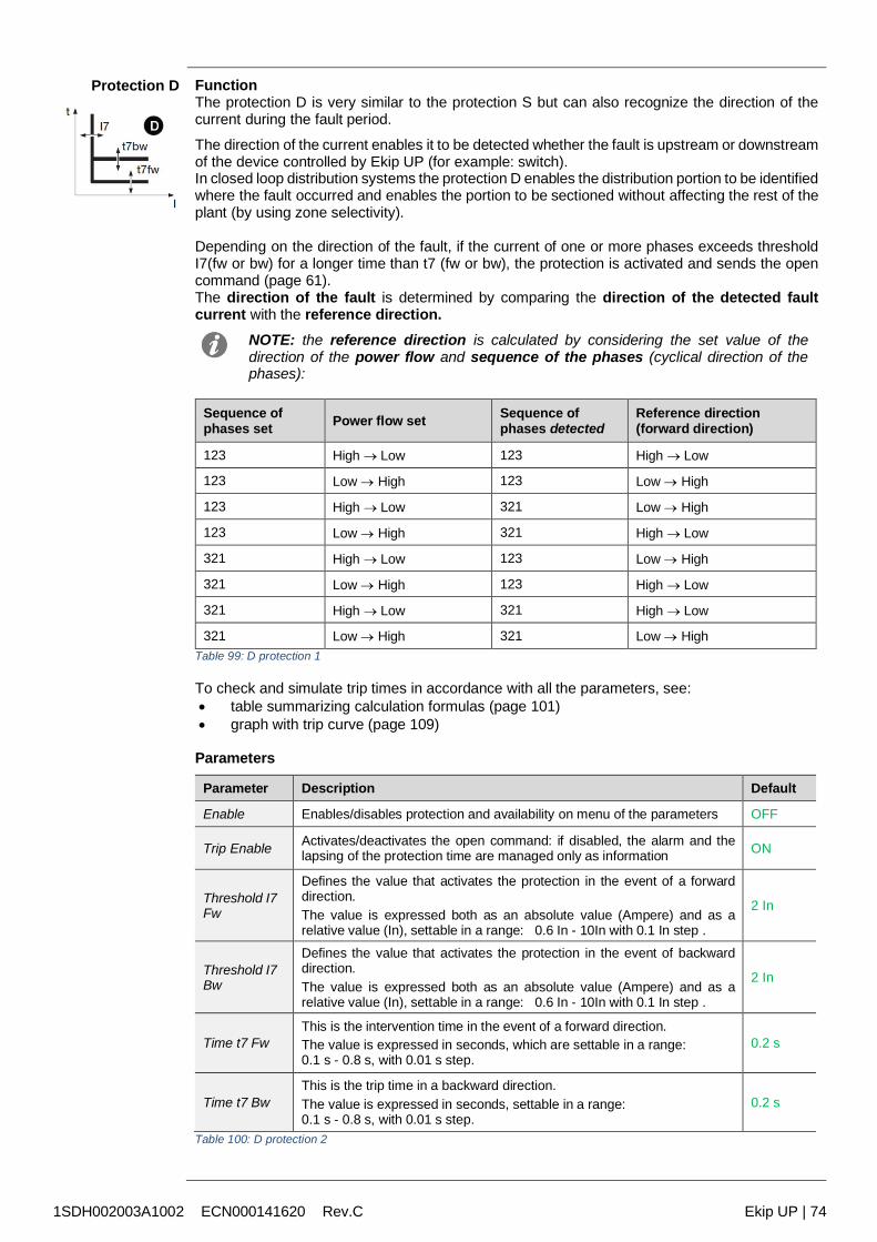
1SDH002003A1002 ECN000141620 Rev.C Ekip UP | 74
Protection D FunctionThe protection D is very similar to the protection S but can also recognize the direction of thecurrent during the fault period.
The direction of the current enables it to be detected whether the fault is upstream or downstreamof the device controlled by Ekip UP (for example: switch).In closed loop distribution systems the protection D enables the distribution portion to be identifiedwhere the fault occurred and enables the portion to be sectioned without affecting the rest of theplant (by using zone selectivity).
Depending on the direction of the fault, if the current of one or more phases exceeds thresholdI7(fw or bw) for a longer time than t7 (fw or bw), the protection is activated and sends the opencommand (page 61).The direction of the fault is determined by comparing the direction of the detected faultcurrent with the reference direction.
NOTE: the reference direction is calculated by considering the set value of thedirection of the power flow and sequence of the phases (cyclical direction of thephases):
Sequence ofphases set Power flow set Sequence of
phases detectedReference direction(forward direction)
123 High Low 123 High Low
123 Low High 123 Low High
123 High Low 321 Low High
123 Low High 321 High Low
321 High Low 123 Low High
321 Low High 123 High Low
321 High Low 321 High Low
321 Low High 321 Low HighTable 99: D protection 1
To check and simulate trip times in accordance with all the parameters, see: table summarizing calculation formulas (page 101) graph with trip curve (page 109)
Parameters
Parameter Description Default
Enable Enables/disables protection and availability on menu of the parameters OFF
Trip Enable Activates/deactivates the open command: if disabled, the alarm and thelapsing of the protection time are managed only as information ON
Threshold I7Fw
Defines the value that activates the protection in the event of a forwarddirection.The value is expressed both as an absolute value (Ampere) and as arelative value (In), settable in a range: 0.6 In - 10In with 0.1 In step .
2 In
Threshold I7Bw
Defines the value that activates the protection in the event of backwarddirection.The value is expressed both as an absolute value (Ampere) and as arelative value (In), settable in a range: 0.6 In - 10In with 0.1 In step .
2 In
Time t7 FwThis is the intervention time in the event of a forward direction.The value is expressed in seconds, which are settable in a range:0.1 s - 0.8 s, with 0.01 s step.
0.2 s
Time t7 BwThis is the trip time in a backward direction.The value is expressed in seconds, settable in a range:0.1 s - 0.8 s, with 0.01 s step.
0.2 s
Table 100: D protection 2
1SDH002003A1002 ECN000141620 Rev.C Ekip UP | 75
Protection D [2] Parameter Description Default
ZoneSelectivity
Activates/deactivates the function and the display availability ofselectivity time, see page 80 for details
NOTE: for correct operation of selectivity D, configureOFF selectivity S, S2, G and Gext
OFF
Fwselectivitytime
This is the trip time of the protection with the zone selectivityfunction active, forward direction and selectivity input Fw notpresent, see page 80for detailsThe value is expressed in seconds, which are settable in a range:0.1 s - 0.8 s, with 0.01 s step.
0.13 s
Bwselectivitytime
This is the trip time of the protection with the zone selectivityfunction active, backward direction and selectivity input Bw notpresent, see page 80for detailsThe value is expressed in seconds, which are settable in a range:0.1 s - 0.8 s, with 0.01 s step.
0.13 s
StartUpenable
Activates/deactivates the function and display availability of thecombined parameters, see page 81 for details OFF
StartUpthresholdFw
Protection threshold valid during Startup time, in the conditions inwhich the function is active and with forward current direction, seepage 81 for detailsThe value is expressed both as an absolute value (Ampere) and asa relative value (In), settable in a range:0.6 In - 10In with 0.1 In step .
2 In
StartUpthresholdBw
Protection threshold valid during Startup time, in the conditions inwhich the function is active and with backward current direction,see page 81 for detailsThe value is expressed both as an absolute value (Ampere) and asa relative value (In), settable in a range:0.6 In - 10In with 0.1 In step .
2 In
StartUp time
This is the time for which the StartUp threshold is active, calculatedfrom tripping of activation threshold, set details on page 81The value is expressed in seconds, which are settable in a range:0.1 s - 30 s, with 0.01 s step.
0.1 s
Min AngleDirection
Ekip UP calculates the phase displacement angle betweenmeasured reactive power and measured power: when the phasedisplacement becomes greater than the set Min Angle Directionparameter, the unit considers the fault directionThe value is expressed in degrees, which are settable in a range of15 values from 3.6 ° to 69.6 °
3.6 °
Table 101: D protection 3
Constraints, limits and additional functions from the service connector (via Ekip Connect) or with a system bus communication, also
locking functions and selectivity type and the Trip only Forward and Trip Only Backwardparameters can be accessed, see page 78
Applicational Notes By activating direction protection D, the alarm is automatically activated that controls the
phase sequence (which can be overridden and activated also manually): note that in theevent of of a cyclical sequence of the phases that is different from the set value, the directionprotection reverses the reference direction in the case of a fault.The details of the phase sequence protection are available on page 85.
The behaviour of the direction protection is affected by small load overcurrents: in the eventof capacitive load, to avoid the possibility of incorrect identification of the direction of thefault current, it is suggested that the adjustment of this protection refers to real faultconditions and not to overloads.
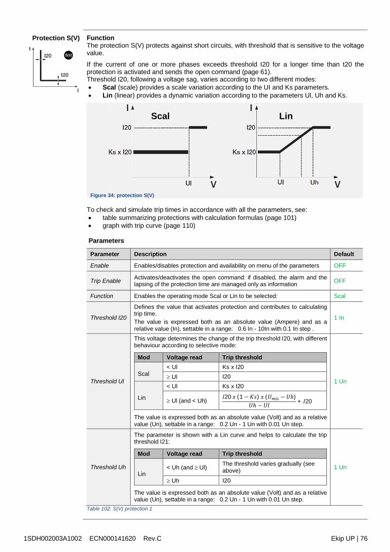
1SDH002003A1002 ECN000141620 Rev.C Ekip UP | 76
Protection S(V) FunctionThe protection S(V) protects against short circuits, with threshold that is sensitive to the voltagevalue.
If the current of one or more phases exceeds threshold I20 for a longer time than t20 theprotection is activated and sends the open command (page 61).Threshold I20, following a voltage sag, varies according to two different modes: Scal (scale) provides a scale variation according to the UI and Ks parameters. Lin (linear) provides a dynamic variation according to the parameters Ul, Uh and Ks.
Figure 34: protection S(V)
To check and simulate trip times in accordance with all the parameters, see: table summarizing protections with calculation formulas (page 101) graph with trip curve (page 110)
Parameters
Parameter Description Default
Enable Enables/disables protection and availability on menu of the parameters OFF
Trip Enable Activates/deactivates the open command: if disabled, the alarm and thelapsing of the protection time are managed only as information OFF
Function Enables the operating mode Scal or Lin to be selected: Scal
Threshold I20
Defines the value that activates protection and contributes to calculatingtrip time.The value is expressed both as an absolute value (Ampere) and as arelative value (In), settable in a range: 0.6 In - 10In with 0.1 In step .
1 In
Threshold Ul
This voltage determines the change of the trip threshold I20, with differentbehaviour according to selective mode:
Mod Voltage read Trip threshold
Scal< Ul Ks x I20 Ul I20
Lin
< Ul Ks x I20
Ul (and < Uh) 𝐼20 𝑥 (1−𝐾𝑠) 𝑥 (𝑈𝑚𝑖𝑠 − 𝑈ℎ)𝑈ℎ − 𝑈𝑙 + 𝐼20
The value is expressed both as an absolute value (Volt) and as a relativevalue (Un), settable in a range: 0.2 Un - 1 Un with 0.01 Un step.
1 Un
Threshold Uh
The parameter is shown with a Lin curve and helps to calculate the tripthreshold I21:
Mod Voltage read Trip threshold
Lin< Uh (and Ul) The threshold varies gradually (see
above) Uh I20
The value is expressed both as an absolute value (Volt) and as a relativevalue (Un), settable in a range: 0.2 Un - 1 Un with 0.01 Un step.
1 Un
Table 102: S(V) protection 1
Scal Lin
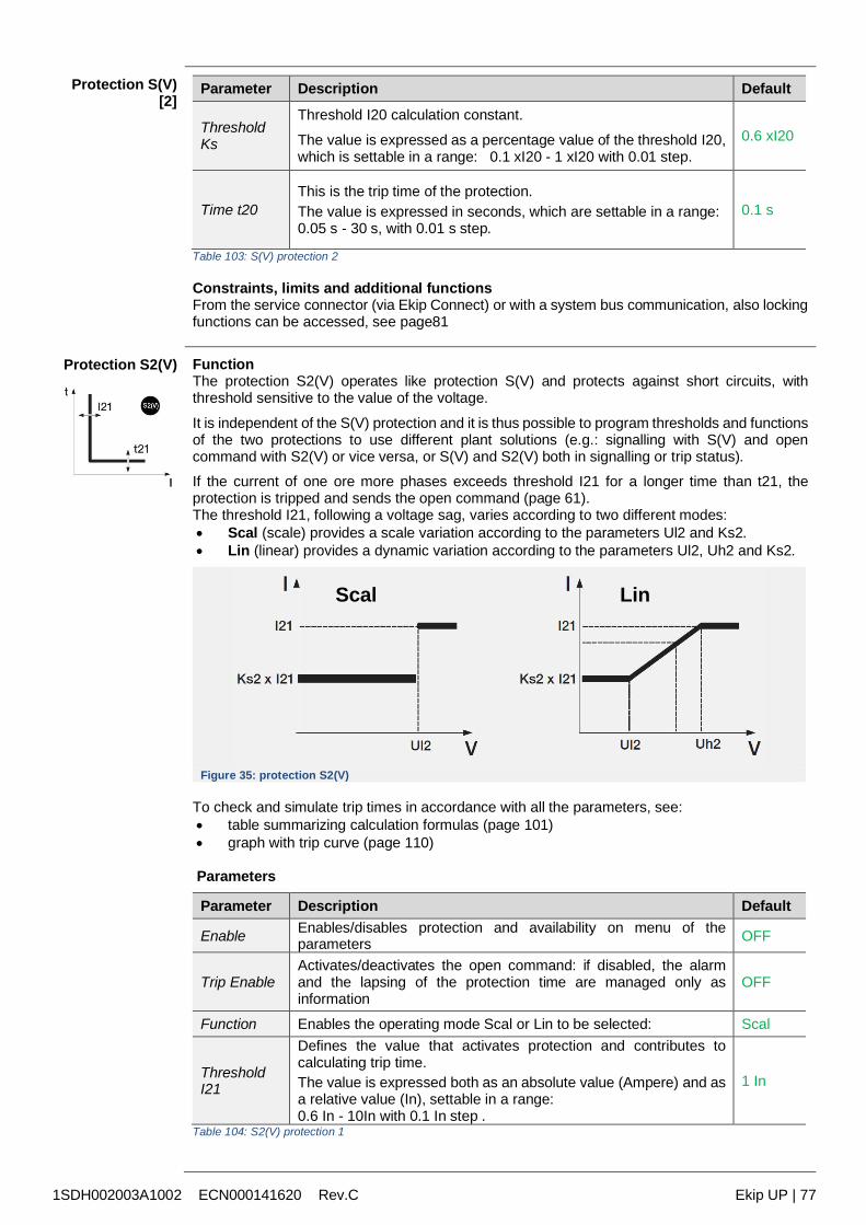
1SDH002003A1002 ECN000141620 Rev.C Ekip UP | 77
Protection S(V)[2]
Parameter Description Default
ThresholdKs
Threshold I20 calculation constant.
The value is expressed as a percentage value of the threshold I20,which is settable in a range: 0.1 xI20 - 1 xI20 with 0.01 step.
0.6 xI20
Time t20This is the trip time of the protection.The value is expressed in seconds, which are settable in a range:0.05 s - 30 s, with 0.01 s step.
0.1 s
Table 103: S(V) protection 2
Constraints, limits and additional functionsFrom the service connector (via Ekip Connect) or with a system bus communication, also lockingfunctions can be accessed, see page81
Protection S2(V) FunctionThe protection S2(V) operates like protection S(V) and protects against short circuits, withthreshold sensitive to the value of the voltage.
It is independent of the S(V) protection and it is thus possible to program thresholds and functionsof the two protections to use different plant solutions (e.g.: signalling with S(V) and opencommand with S2(V) or vice versa, or S(V) and S2(V) both in signalling or trip status).If the current of one ore more phases exceeds threshold I21 for a longer time than t21, theprotection is tripped and sends the open command (page 61).The threshold I21, following a voltage sag, varies according to two different modes: Scal (scale) provides a scale variation according to the parameters Ul2 and Ks2. Lin (linear) provides a dynamic variation according to the parameters Ul2, Uh2 and Ks2.
Figure 35: protection S2(V)
To check and simulate trip times in accordance with all the parameters, see: table summarizing calculation formulas (page 101) graph with trip curve (page 110)
Parameters
Parameter Description Default
Enable Enables/disables protection and availability on menu of theparameters OFF
Trip EnableActivates/deactivates the open command: if disabled, the alarmand the lapsing of the protection time are managed only asinformation
OFF
Function Enables the operating mode Scal or Lin to be selected: Scal
ThresholdI21
Defines the value that activates protection and contributes tocalculating trip time.The value is expressed both as an absolute value (Ampere) and asa relative value (In), settable in a range:0.6 In - 10In with 0.1 In step .
1 In
Table 104: S2(V) protection 1
Scal Lin
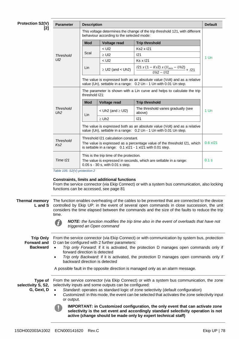
1SDH002003A1002 ECN000141620 Rev.C Ekip UP | 78
Protection S2(V)[2]
Parameter Description Default
ThresholdUl2
This voltage determines the change of the trip threshold 121, with differentbehaviour according to the selected mode:
Mod Voltage read Trip threshold
Scal< Ul2 Ks2 x I21 Ul2 I21
Lin
< Ul2 Ks x I21
Ul2 (and < Uh2) 𝐼21 𝑥 (1−𝐾𝑠2) 𝑥 (𝑈𝑚𝑖𝑠 − 𝑈ℎ2)𝑈ℎ2−𝑈𝑙2 + 𝐼21
The value is expressed both as an absolute value (Volt) and as a relativevalue (Un), settable in a range: 0.2 Un - 1 Un with 0.01 Un step.
1 Un
ThresholdUh2
The parameter is shown with a Lin curve and helps to calculate the tripthreshold I21:
Mod Voltage read Trip threshold
Lin< Uh2 (and Ul2) The threshold varies gradually (see
above)
Uh2 I21
The value is expressed both as an absolute value (Volt) and as a relativevalue (Un), settable in a range: 0.2 Un - 1 Un with 0.01 Un step.
1 Un
ThresholdKs2
Threshold I21 calculation constant.The value is expressed as a percentage value of the threshold I21, whichis settable in a range: 0.1 xI21 - 1 xI21 with 0.01 step.
0.6 xI21
Time t21This is the trip time of the protection.The value is expressed in seconds, which are settable in a range:0.05 s - 30 s, with 0.01 s step.
0.1 s
Table 105: S2(V) protection 2
Constraints, limits and additional functionsFrom the service connector (via Ekip Connect) or with a system bus communication, also lockingfunctions can be accessed, see page 81
Thermal memoryL and S
The function enables overheating of the cables to be prevented that are connected to the devicecontrolled by Ekip UP: in the event of several open commands in close succession, the unitconsiders the time elapsed between the commands and the size of the faults to reduce the triptime.
NOTE: the function modifies the trip time also in the event of overloads that have nottriggered an Open command
Trip OnlyForward and
Backward
From the service connector (via Ekip Connect) or with communication by system bus, protectionD can be configured with 2 further parameters: Trip only Forward: if it is activated, the protection D manages open commands only if
forward direction is detected Trip only Backward: if it is activated, the protection D manages open commands only if
backward direction is detected
A possible fault in the opposite direction is managed only as an alarm message.
Type ofselectivity S, S2,
G, Gext, D
From the service connector (via Ekip Connect) or with a system bus communication, the zoneselectivity inputs and some outputs can be configured: Standard: operates as standard logic of zone selectivity (default configuration) Customized: in this mode, the event can be selected that activates the zone selectivity input
or output.
IMPORTANT: in Customized configuration, the only event that can activate zoneselectivity is the set event and accordingly standard selectivity operation is notactive (change should be made only by expert technical staff)
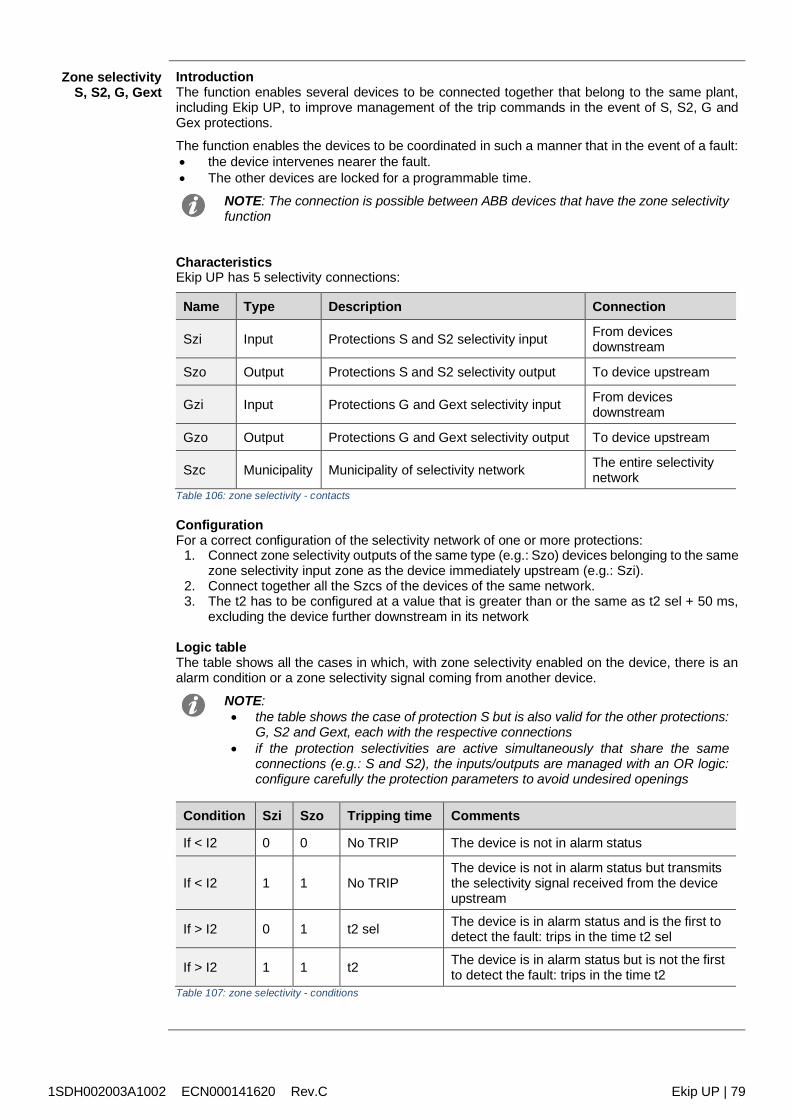
1SDH002003A1002 ECN000141620 Rev.C Ekip UP | 79
Zone selectivityS, S2, G, Gext
IntroductionThe function enables several devices to be connected together that belong to the same plant,including Ekip UP, to improve management of the trip commands in the event of S, S2, G andGex protections.
The function enables the devices to be coordinated in such a manner that in the event of a fault: the device intervenes nearer the fault. The other devices are locked for a programmable time.
NOTE: The connection is possible between ABB devices that have the zone selectivityfunction
CharacteristicsEkip UP has 5 selectivity connections:
Name Type Description Connection
Szi Input Protections S and S2 selectivity input From devicesdownstream
Szo Output Protections S and S2 selectivity output To device upstream
Gzi Input Protections G and Gext selectivity input From devicesdownstream
Gzo Output Protections G and Gext selectivity output To device upstream
Szc Municipality Municipality of selectivity network The entire selectivitynetwork
Table 106: zone selectivity - contacts
ConfigurationFor a correct configuration of the selectivity network of one or more protections:
1. Connect zone selectivity outputs of the same type (e.g.: Szo) devices belonging to the samezone selectivity input zone as the device immediately upstream (e.g.: Szi).
2. Connect together all the Szcs of the devices of the same network.3. The t2 has to be configured at a value that is greater than or the same as t2 sel + 50 ms,
excluding the device further downstream in its network
Logic tableThe table shows all the cases in which, with zone selectivity enabled on the device, there is analarm condition or a zone selectivity signal coming from another device.
NOTE: the table shows the case of protection S but is also valid for the other protections:
G, S2 and Gext, each with the respective connections if the protection selectivities are active simultaneously that share the same
connections (e.g.: S and S2), the inputs/outputs are managed with an OR logic:configure carefully the protection parameters to avoid undesired openings
Condition Szi Szo Tripping time Comments
If < I2 0 0 No TRIP The device is not in alarm status
If < I2 1 1 No TRIPThe device is not in alarm status but transmitsthe selectivity signal received from the deviceupstream
If > I2 0 1 t2 sel The device is in alarm status and is the first todetect the fault: trips in the time t2 sel
If > I2 1 1 t2 The device is in alarm status but is not the firstto detect the fault: trips in the time t2
Table 107: zone selectivity - conditions
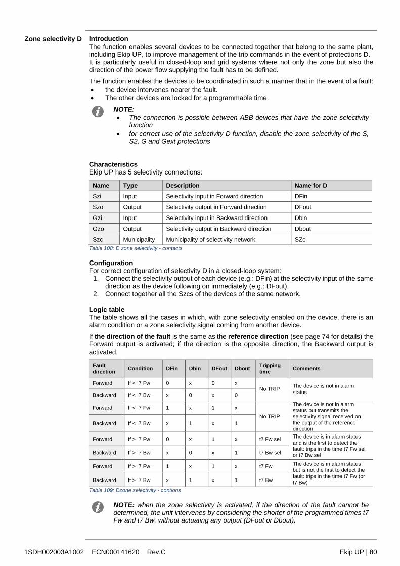
1SDH002003A1002 ECN000141620 Rev.C Ekip UP | 80
Zone selectivity D IntroductionThe function enables several devices to be connected together that belong to the same plant,including Ekip UP, to improve management of the trip commands in the event of protections D.It is particularly useful in closed-loop and grid systems where not only the zone but also thedirection of the power flow supplying the fault has to be defined.The function enables the devices to be coordinated in such a manner that in the event of a fault: the device intervenes nearer the fault. The other devices are locked for a programmable time.
NOTE: The connection is possible between ABB devices that have the zone selectivity
function for correct use of the selectivity D function, disable the zone selectivity of the S,
S2, G and Gext protections
CharacteristicsEkip UP has 5 selectivity connections:
Name Type Description Name for DSzi Input Selectivity input in Forward direction DFin
Szo Output Selectivity output in Forward direction DFout
Gzi Input Selectivity input in Backward direction Dbin
Gzo Output Selectivity output in Backward direction Dbout
Szc Municipality Municipality of selectivity network SZcTable 108: D zone selectivity - contacts
ConfigurationFor correct configuration of selectivity D in a closed-loop system:
1. Connect the selectivity output of each device (e.g.: DFin) at the selectivity input of the samedirection as the device following on immediately (e.g.: DFout).
2. Connect together all the Szcs of the devices of the same network.
Logic tableThe table shows all the cases in which, with zone selectivity enabled on the device, there is analarm condition or a zone selectivity signal coming from another device.
If the direction of the fault is the same as the reference direction (see page 74 for details) theForward output is activated; if the direction is the opposite direction, the Backward output isactivated.
Faultdirection Condition DFin Dbin DFout Dbout Tripping
time Comments
Forward If < I7 Fw 0 x 0 xNo TRIP The device is not in alarm
statusBackward If < I7 Bw x 0 x 0
Forward If < I7 Fw 1 x 1 xNo TRIP
The device is not in alarmstatus but transmits theselectivity signal received onthe output of the referencedirection
Backward If < I7 Bw x 1 x 1
Forward If > I7 Fw 0 x 1 x t7 Fw sel The device is in alarm statusand is the first to detect thefault: trips in the time t7 Fw selor t7 Bw selBackward If > I7 Bw x 0 x 1 t7 Bw sel
Forward If > I7 Fw 1 x 1 x t7 Fw The device is in alarm statusbut is not the first to detect thefault: trips in the time t7 Fw (ort7 Bw)Backward If > I7 Bw x 1 x 1 t7 Bw
Table 109: Dzone selectivity - contions
NOTE: when the zone selectivity is activated, if the direction of the fault cannot bedetermined, the unit intervenes by considering the shorter of the programmed times t7Fw and t7 Bw, without actuating any output (DFout or Dbout).
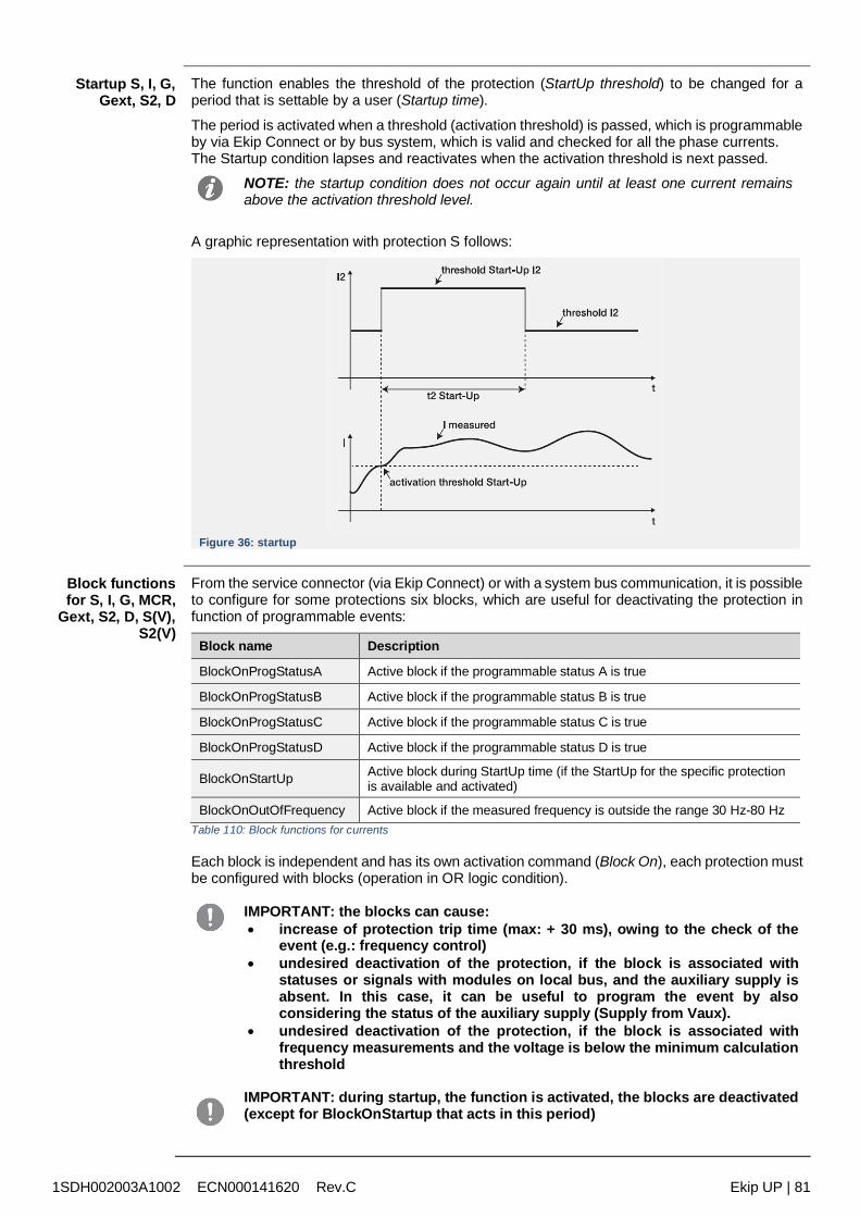
1SDH002003A1002 ECN000141620 Rev.C Ekip UP | 81
Startup S, I, G,Gext, S2, D
The function enables the threshold of the protection (StartUp threshold) to be changed for aperiod that is settable by a user (Startup time).
The period is activated when a threshold (activation threshold) is passed, which is programmableby via Ekip Connect or by bus system, which is valid and checked for all the phase currents.The Startup condition lapses and reactivates when the activation threshold is next passed.
NOTE: the startup condition does not occur again until at least one current remainsabove the activation threshold level.
A graphic representation with protection S follows:
Figure 36: startup
Block functionsfor S, I, G, MCR,
Gext, S2, D, S(V),S2(V)
From the service connector (via Ekip Connect) or with a system bus communication, it is possibleto configure for some protections six blocks, which are useful for deactivating the protection infunction of programmable events:
Block name Description
BlockOnProgStatusA Active block if the programmable status A is true
BlockOnProgStatusB Active block if the programmable status B is true
BlockOnProgStatusC Active block if the programmable status C is true
BlockOnProgStatusD Active block if the programmable status D is true
BlockOnStartUp Active block during StartUp time (if the StartUp for the specific protectionis available and activated)
BlockOnOutOfFrequency Active block if the measured frequency is outside the range 30 Hz-80 HzTable 110: Block functions for currents
Each block is independent and has its own activation command (Block On), each protection mustbe configured with blocks (operation in OR logic condition).
IMPORTANT: the blocks can cause: increase of protection trip time (max: + 30 ms), owing to the check of the
event (e.g.: frequency control) undesired deactivation of the protection, if the block is associated with
statuses or signals with modules on local bus, and the auxiliary supply isabsent. In this case, it can be useful to program the event by alsoconsidering the status of the auxiliary supply (Supply from Vaux).
undesired deactivation of the protection, if the block is associated withfrequency measurements and the voltage is below the minimum calculationthreshold
IMPORTANT: during startup, the function is activated, the blocks are deactivated(except for BlockOnStartup that acts in this period)
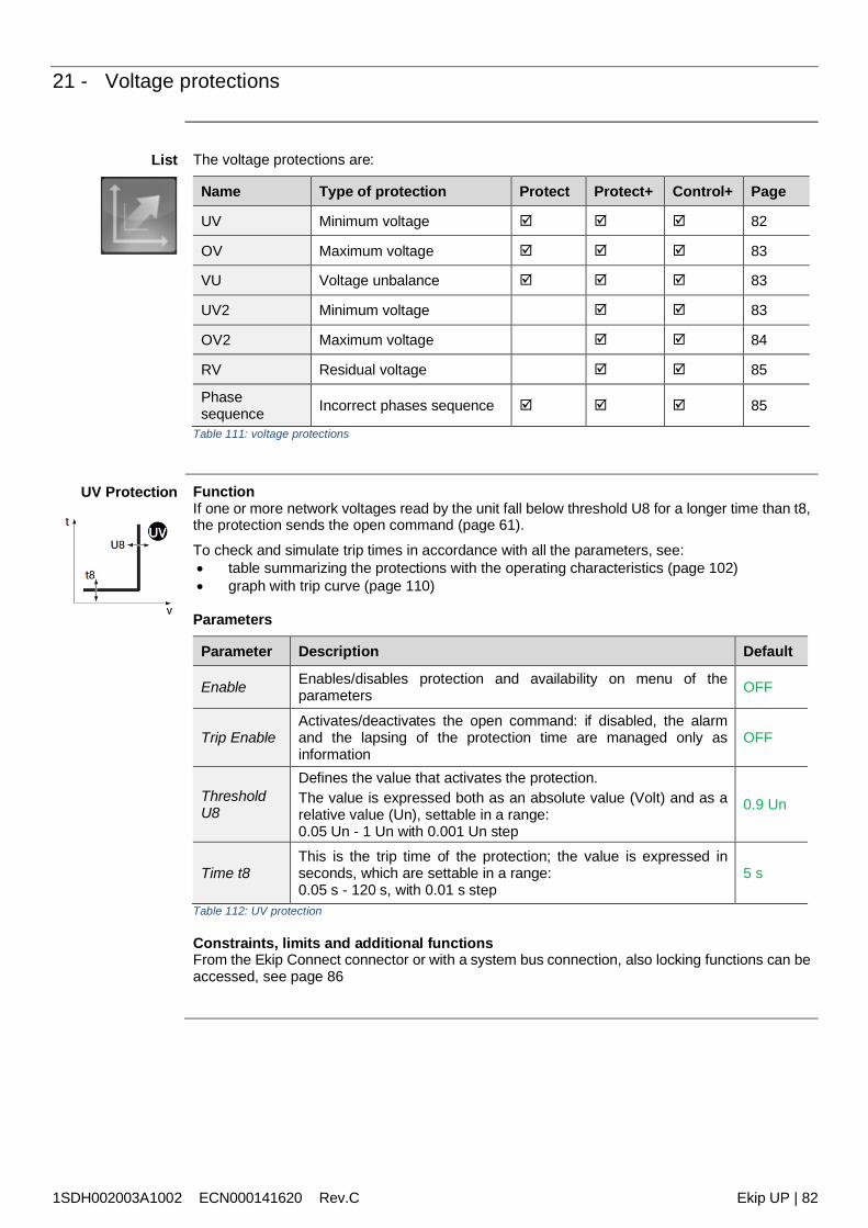
1SDH002003A1002 ECN000141620 Rev.C Ekip UP | 82
21 - Voltage protections
List The voltage protections are:
Name Type of protection Protect Protect+ Control+ Page
UV Minimum voltage 82
OV Maximum voltage 83
VU Voltage unbalance 83
UV2 Minimum voltage 83
OV2 Maximum voltage 84
RV Residual voltage 85
Phasesequence Incorrect phases sequence 85
Table 111: voltage protections
UV Protection FunctionIf one or more network voltages read by the unit fall below threshold U8 for a longer time than t8,the protection sends the open command (page 61).
To check and simulate trip times in accordance with all the parameters, see: table summarizing the protections with the operating characteristics (page 102) graph with trip curve (page 110)
Parameters
Parameter Description Default
Enable Enables/disables protection and availability on menu of theparameters OFF
Trip EnableActivates/deactivates the open command: if disabled, the alarmand the lapsing of the protection time are managed only asinformation
OFF
ThresholdU8
Defines the value that activates the protection.The value is expressed both as an absolute value (Volt) and as arelative value (Un), settable in a range:0.05 Un - 1 Un with 0.001 Un step
0.9 Un
Time t8This is the trip time of the protection; the value is expressed inseconds, which are settable in a range:0.05 s - 120 s, with 0.01 s step
5 s
Table 112: UV protection
Constraints, limits and additional functionsFrom the Ekip Connect connector or with a system bus connection, also locking functions can beaccessed, see page 86
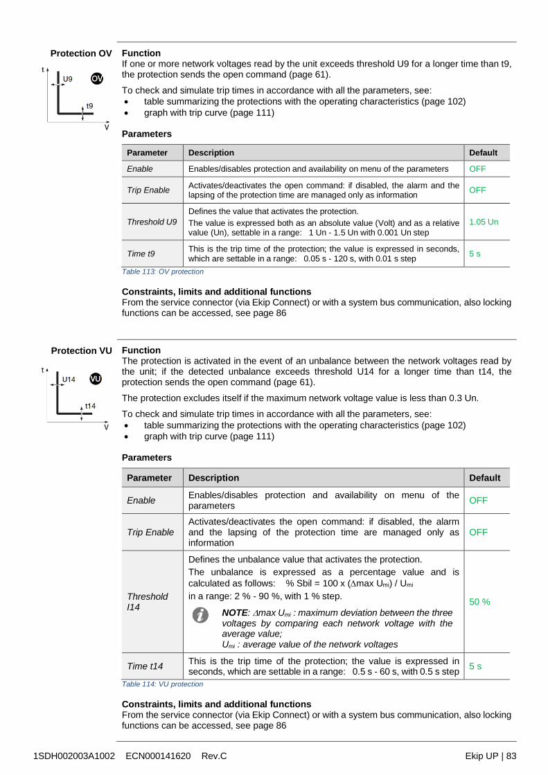
1SDH002003A1002 ECN000141620 Rev.C Ekip UP | 83
Protection OV FunctionIf one or more network voltages read by the unit exceeds threshold U9 for a longer time than t9,the protection sends the open command (page 61).
To check and simulate trip times in accordance with all the parameters, see: table summarizing the protections with the operating characteristics (page 102) graph with trip curve (page 111)
Parameters
Parameter Description Default
Enable Enables/disables protection and availability on menu of the parameters OFF
Trip Enable Activates/deactivates the open command: if disabled, the alarm and thelapsing of the protection time are managed only as information OFF
Threshold U9Defines the value that activates the protection.The value is expressed both as an absolute value (Volt) and as a relativevalue (Un), settable in a range: 1 Un - 1.5 Un with 0.001 Un step
1.05 Un
Time t9 This is the trip time of the protection; the value is expressed in seconds,which are settable in a range: 0.05 s - 120 s, with 0.01 s step 5 s
Table 113: OV protection
Constraints, limits and additional functionsFrom the service connector (via Ekip Connect) or with a system bus communication, also lockingfunctions can be accessed, see page 86
Protection VU FunctionThe protection is activated in the event of an unbalance between the network voltages read bythe unit; if the detected unbalance exceeds threshold U14 for a longer time than t14, theprotection sends the open command (page 61).
The protection excludes itself if the maximum network voltage value is less than 0.3 Un.
To check and simulate trip times in accordance with all the parameters, see: table summarizing the protections with the operating characteristics (page 102) graph with trip curve (page 111)
Parameters
Parameter Description Default
Enable Enables/disables protection and availability on menu of theparameters OFF
Trip EnableActivates/deactivates the open command: if disabled, the alarmand the lapsing of the protection time are managed only asinformation
OFF
ThresholdI14
Defines the unbalance value that activates the protection.The unbalance is expressed as a percentage value and iscalculated as follows: % Sbil = 100 x (max Umi) / Umi
in a range: 2 % - 90 %, with 1 % step.
NOTE: max Umi : maximum deviation between the threevoltages by comparing each network voltage with theaverage value;Umi : average value of the network voltages
50 %
Time t14 This is the trip time of the protection; the value is expressed inseconds, which are settable in a range: 0.5 s - 60 s, with 0.5 s step 5 s
Table 114: VU protection
Constraints, limits and additional functionsFrom the service connector (via Ekip Connect) or with a system bus communication, also lockingfunctions can be accessed, see page 86
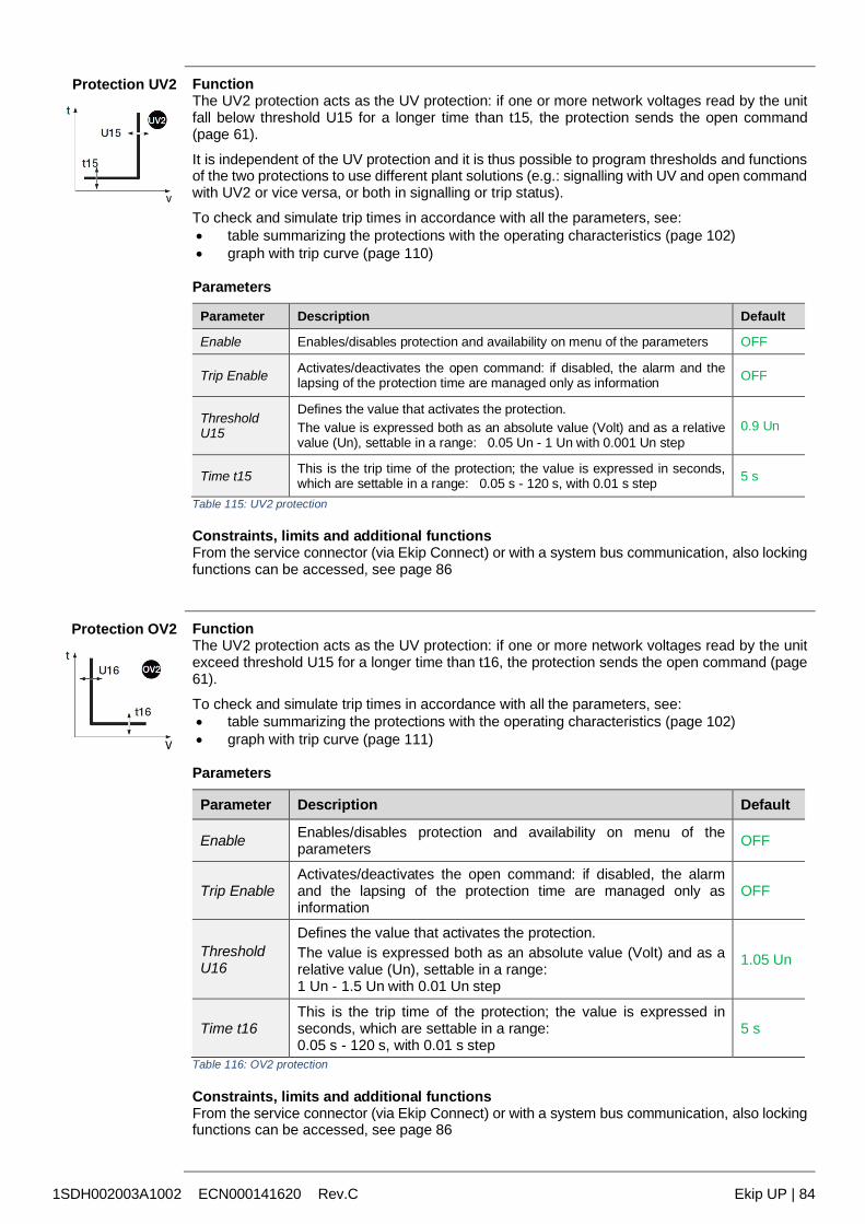
1SDH002003A1002 ECN000141620 Rev.C Ekip UP | 84
Protection UV2 FunctionThe UV2 protection acts as the UV protection: if one or more network voltages read by the unitfall below threshold U15 for a longer time than t15, the protection sends the open command(page 61).
It is independent of the UV protection and it is thus possible to program thresholds and functionsof the two protections to use different plant solutions (e.g.: signalling with UV and open commandwith UV2 or vice versa, or both in signalling or trip status).
To check and simulate trip times in accordance with all the parameters, see: table summarizing the protections with the operating characteristics (page 102) graph with trip curve (page 110)
Parameters
Parameter Description Default
Enable Enables/disables protection and availability on menu of the parameters OFF
Trip Enable Activates/deactivates the open command: if disabled, the alarm and thelapsing of the protection time are managed only as information OFF
ThresholdU15
Defines the value that activates the protection.The value is expressed both as an absolute value (Volt) and as a relativevalue (Un), settable in a range: 0.05 Un - 1 Un with 0.001 Un step
0.9 Un
Time t15 This is the trip time of the protection; the value is expressed in seconds,which are settable in a range: 0.05 s - 120 s, with 0.01 s step 5 s
Table 115: UV2 protection
Constraints, limits and additional functionsFrom the service connector (via Ekip Connect) or with a system bus communication, also lockingfunctions can be accessed, see page 86
Protection OV2 FunctionThe UV2 protection acts as the UV protection: if one or more network voltages read by the unitexceed threshold U15 for a longer time than t16, the protection sends the open command (page61).
To check and simulate trip times in accordance with all the parameters, see: table summarizing the protections with the operating characteristics (page 102) graph with trip curve (page 111)
Parameters
Parameter Description Default
Enable Enables/disables protection and availability on menu of theparameters OFF
Trip EnableActivates/deactivates the open command: if disabled, the alarmand the lapsing of the protection time are managed only asinformation
OFF
ThresholdU16
Defines the value that activates the protection.The value is expressed both as an absolute value (Volt) and as arelative value (Un), settable in a range:1 Un - 1.5 Un with 0.01 Un step
1.05 Un
Time t16This is the trip time of the protection; the value is expressed inseconds, which are settable in a range:0.05 s - 120 s, with 0.01 s step
5 s
Table 116: OV2 protection
Constraints, limits and additional functionsFrom the service connector (via Ekip Connect) or with a system bus communication, also lockingfunctions can be accessed, see page 86
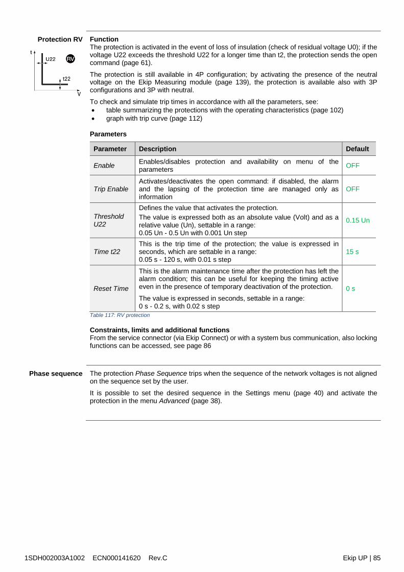
1SDH002003A1002 ECN000141620 Rev.C Ekip UP | 85
Protection RV FunctionThe protection is activated in the event of loss of insulation (check of residual voltage U0); if thevoltage U22 exceeds the threshold U22 for a longer time than t2, the protection sends the opencommand (page 61).
The protection is still available in 4P configuration; by activating the presence of the neutralvoltage on the Ekip Measuring module (page 139), the protection is available also with 3Pconfigurations and 3P with neutral.
To check and simulate trip times in accordance with all the parameters, see: table summarizing the protections with the operating characteristics (page 102) graph with trip curve (page 112)
Parameters
Parameter Description Default
Enable Enables/disables protection and availability on menu of theparameters OFF
Trip EnableActivates/deactivates the open command: if disabled, the alarmand the lapsing of the protection time are managed only asinformation
OFF
ThresholdU22
Defines the value that activates the protection.The value is expressed both as an absolute value (Volt) and as arelative value (Un), settable in a range:0.05 Un - 0.5 Un with 0.001 Un step
0.15 Un
Time t22This is the trip time of the protection; the value is expressed inseconds, which are settable in a range:0.05 s - 120 s, with 0.01 s step
15 s
Reset Time
This is the alarm maintenance time after the protection has left thealarm condition; this can be useful for keeping the timing activeeven in the presence of temporary deactivation of the protection.
The value is expressed in seconds, settable in a range:0 s - 0.2 s, with 0.02 s step
0 s
Table 117: RV protection
Constraints, limits and additional functionsFrom the service connector (via Ekip Connect) or with a system bus communication, also lockingfunctions can be accessed, see page 86
Phase sequence The protection Phase Sequence trips when the sequence of the network voltages is not alignedon the sequence set by the user.
It is possible to set the desired sequence in the Settings menu (page 40) and activate theprotection in the menu Advanced (page 38).
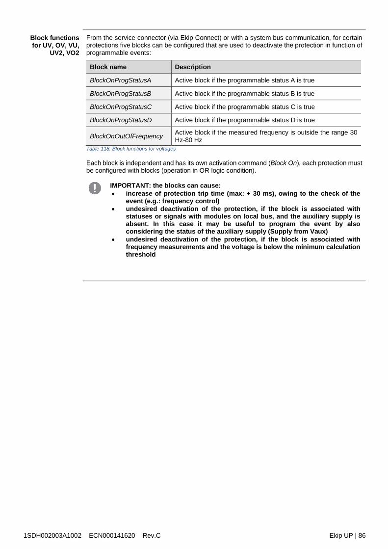
1SDH002003A1002 ECN000141620 Rev.C Ekip UP | 86
Block functionsfor UV, OV, VU,
UV2, VO2
From the service connector (via Ekip Connect) or with a system bus communication, for certainprotections five blocks can be configured that are used to deactivate the protection in function ofprogrammable events:
Block name Description
BlockOnProgStatusA Active block if the programmable status A is true
BlockOnProgStatusB Active block if the programmable status B is true
BlockOnProgStatusC Active block if the programmable status C is true
BlockOnProgStatusD Active block if the programmable status D is true
BlockOnOutOfFrequency Active block if the measured frequency is outside the range 30Hz-80 Hz
Table 118: Block functions for voltages
Each block is independent and has its own activation command (Block On), each protection mustbe configured with blocks (operation in OR logic condition).
IMPORTANT: the blocks can cause: increase of protection trip time (max: + 30 ms), owing to the check of the
event (e.g.: frequency control) undesired deactivation of the protection, if the block is associated with
statuses or signals with modules on local bus, and the auxiliary supply isabsent. In this case it may be useful to program the event by alsoconsidering the status of the auxiliary supply (Supply from Vaux)
undesired deactivation of the protection, if the block is associated withfrequency measurements and the voltage is below the minimum calculationthreshold
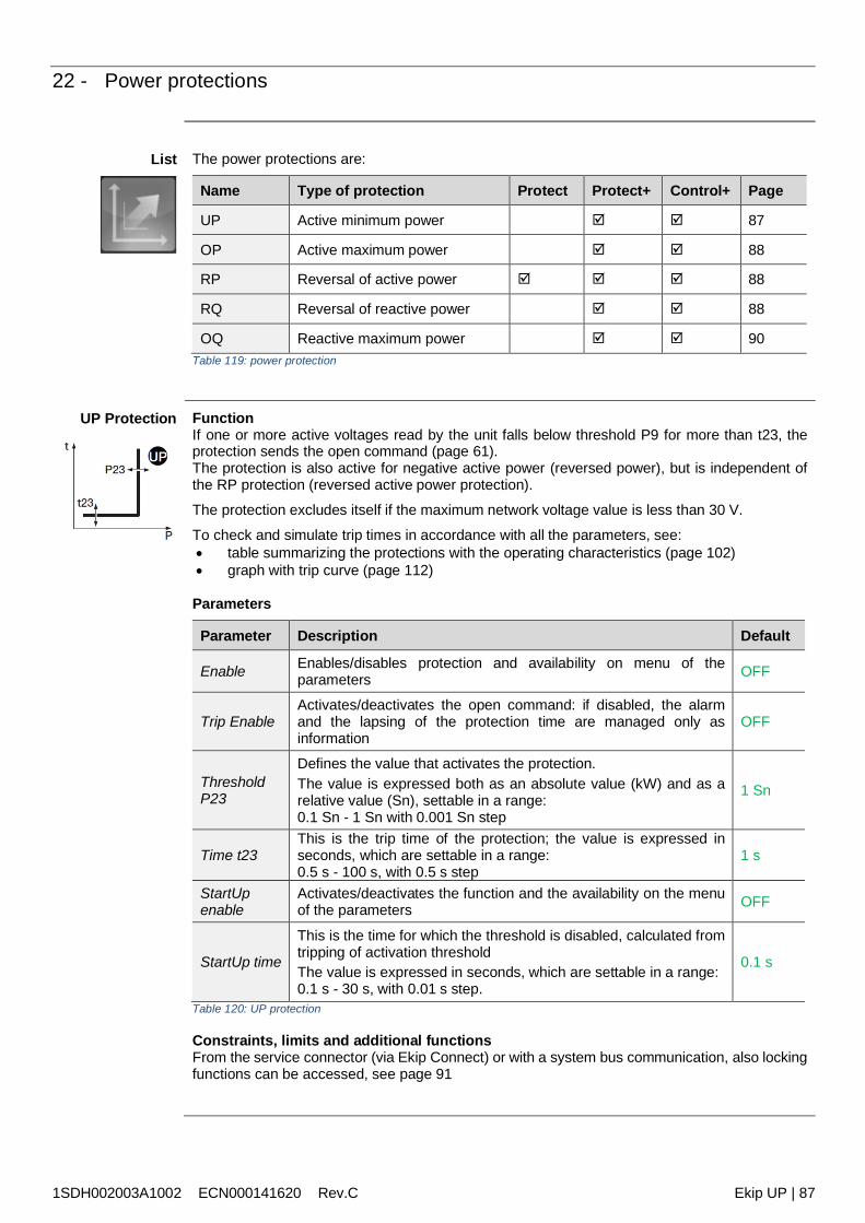
1SDH002003A1002 ECN000141620 Rev.C Ekip UP | 87
22 - Power protections
List The power protections are:
Name Type of protection Protect Protect+ Control+ Page
UP Active minimum power 87
OP Active maximum power 88
RP Reversal of active power 88
RQ Reversal of reactive power 88
OQ Reactive maximum power 90Table 119: power protection
UP Protection FunctionIf one or more active voltages read by the unit falls below threshold P9 for more than t23, theprotection sends the open command (page 61).The protection is also active for negative active power (reversed power), but is independent ofthe RP protection (reversed active power protection).
The protection excludes itself if the maximum network voltage value is less than 30 V.
To check and simulate trip times in accordance with all the parameters, see: table summarizing the protections with the operating characteristics (page 102) graph with trip curve (page 112)
Parameters
Parameter Description Default
Enable Enables/disables protection and availability on menu of theparameters OFF
Trip EnableActivates/deactivates the open command: if disabled, the alarmand the lapsing of the protection time are managed only asinformation
OFF
ThresholdP23
Defines the value that activates the protection.The value is expressed both as an absolute value (kW) and as arelative value (Sn), settable in a range:0.1 Sn - 1 Sn with 0.001 Sn step
1 Sn
Time t23This is the trip time of the protection; the value is expressed inseconds, which are settable in a range:0.5 s - 100 s, with 0.5 s step
1 s
StartUpenable
Activates/deactivates the function and the availability on the menuof the parameters OFF
StartUp time
This is the time for which the threshold is disabled, calculated fromtripping of activation thresholdThe value is expressed in seconds, which are settable in a range:0.1 s - 30 s, with 0.01 s step.
0.1 s
Table 120: UP protection
Constraints, limits and additional functionsFrom the service connector (via Ekip Connect) or with a system bus communication, also lockingfunctions can be accessed, see page 91
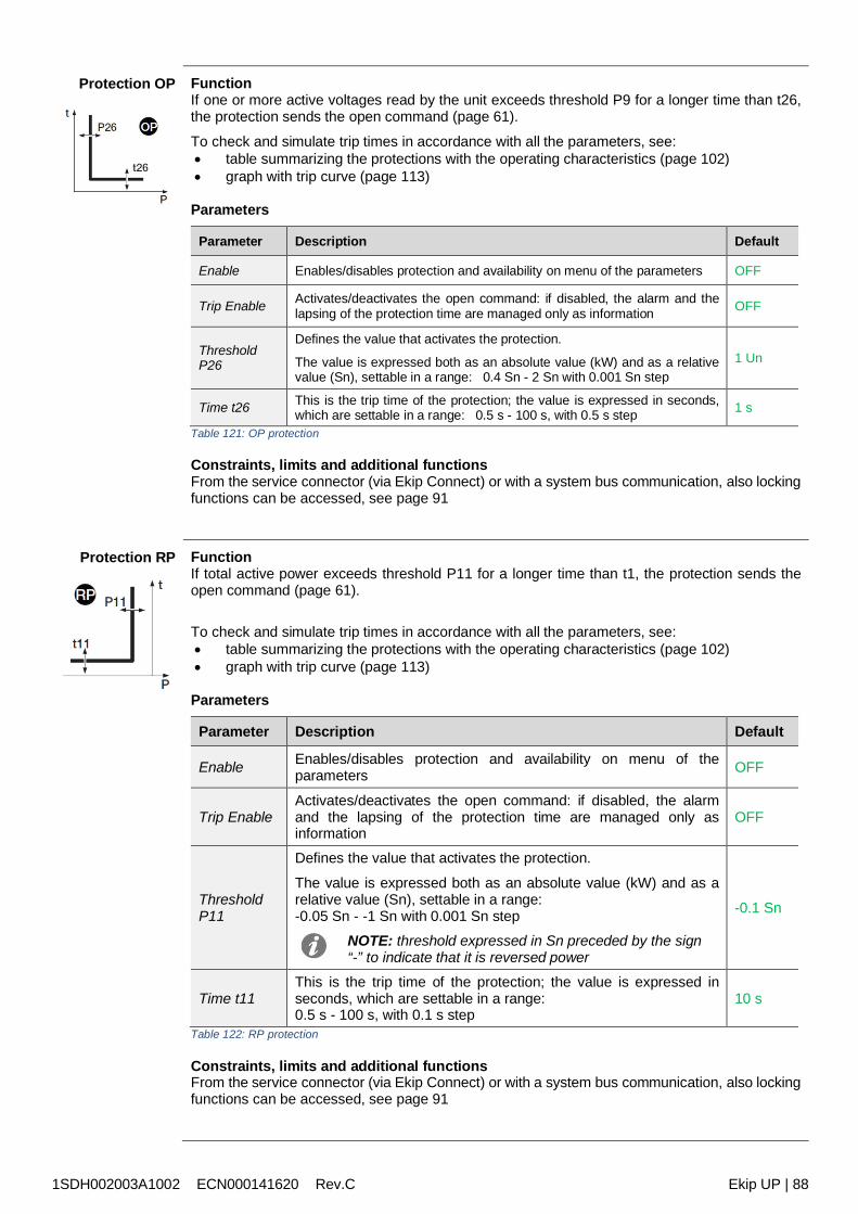
1SDH002003A1002 ECN000141620 Rev.C Ekip UP | 88
Protection OP FunctionIf one or more active voltages read by the unit exceeds threshold P9 for a longer time than t26,the protection sends the open command (page 61).
To check and simulate trip times in accordance with all the parameters, see: table summarizing the protections with the operating characteristics (page 102) graph with trip curve (page 113)
Parameters
Parameter Description Default
Enable Enables/disables protection and availability on menu of the parameters OFF
Trip Enable Activates/deactivates the open command: if disabled, the alarm and thelapsing of the protection time are managed only as information OFF
ThresholdP26
Defines the value that activates the protection.
The value is expressed both as an absolute value (kW) and as a relativevalue (Sn), settable in a range: 0.4 Sn - 2 Sn with 0.001 Sn step
1 Un
Time t26 This is the trip time of the protection; the value is expressed in seconds,which are settable in a range: 0.5 s - 100 s, with 0.5 s step 1 s
Table 121: OP protection
Constraints, limits and additional functionsFrom the service connector (via Ekip Connect) or with a system bus communication, also lockingfunctions can be accessed, see page 91
Protection RP FunctionIf total active power exceeds threshold P11 for a longer time than t1, the protection sends theopen command (page 61).
To check and simulate trip times in accordance with all the parameters, see: table summarizing the protections with the operating characteristics (page 102) graph with trip curve (page 113)
Parameters
Parameter Description Default
Enable Enables/disables protection and availability on menu of theparameters OFF
Trip EnableActivates/deactivates the open command: if disabled, the alarmand the lapsing of the protection time are managed only asinformation
OFF
ThresholdP11
Defines the value that activates the protection.
The value is expressed both as an absolute value (kW) and as arelative value (Sn), settable in a range:-0.05 Sn - -1 Sn with 0.001 Sn step
NOTE: threshold expressed in Sn preceded by the sign“-” to indicate that it is reversed power
-0.1 Sn
Time t11This is the trip time of the protection; the value is expressed inseconds, which are settable in a range:0.5 s - 100 s, with 0.1 s step
10 s
Table 122: RP protection
Constraints, limits and additional functionsFrom the service connector (via Ekip Connect) or with a system bus communication, also lockingfunctions can be accessed, see page 91
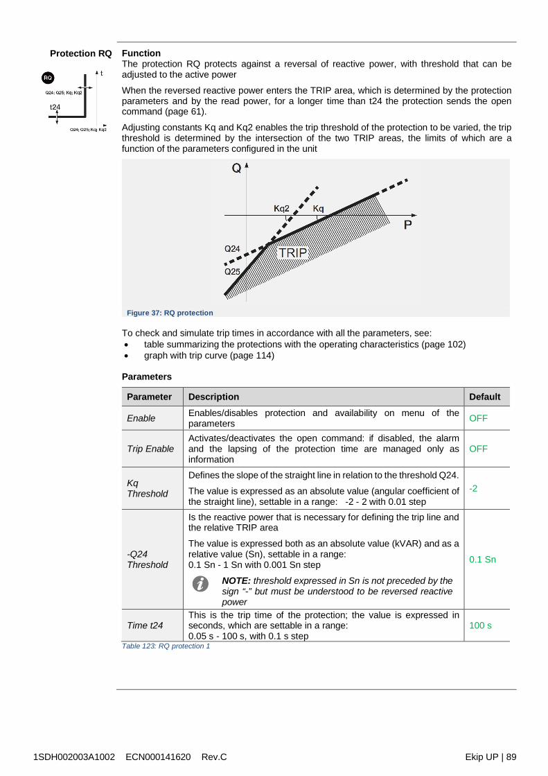
1SDH002003A1002 ECN000141620 Rev.C Ekip UP | 89
Protection RQ FunctionThe protection RQ protects against a reversal of reactive power, with threshold that can beadjusted to the active power
When the reversed reactive power enters the TRIP area, which is determined by the protectionparameters and by the read power, for a longer time than t24 the protection sends the opencommand (page 61).
Adjusting constants Kq and Kq2 enables the trip threshold of the protection to be varied, the tripthreshold is determined by the intersection of the two TRIP areas, the limits of which are afunction of the parameters configured in the unit
Figure 37: RQ protection
To check and simulate trip times in accordance with all the parameters, see: table summarizing the protections with the operating characteristics (page 102) graph with trip curve (page 114)
Parameters
Parameter Description Default
Enable Enables/disables protection and availability on menu of theparameters OFF
Trip EnableActivates/deactivates the open command: if disabled, the alarmand the lapsing of the protection time are managed only asinformation
OFF
KqThreshold
Defines the slope of the straight line in relation to the threshold Q24.
The value is expressed as an absolute value (angular coefficient ofthe straight line), settable in a range: -2 - 2 with 0.01 step
-2
-Q24Threshold
Is the reactive power that is necessary for defining the trip line andthe relative TRIP area
The value is expressed both as an absolute value (kVAR) and as arelative value (Sn), settable in a range:0.1 Sn - 1 Sn with 0.001 Sn step
NOTE: threshold expressed in Sn is not preceded by thesign “-” but must be understood to be reversed reactivepower
0.1 Sn
Time t24This is the trip time of the protection; the value is expressed inseconds, which are settable in a range:0.05 s - 100 s, with 0.1 s step
100 s
Table 123: RQ protection 1
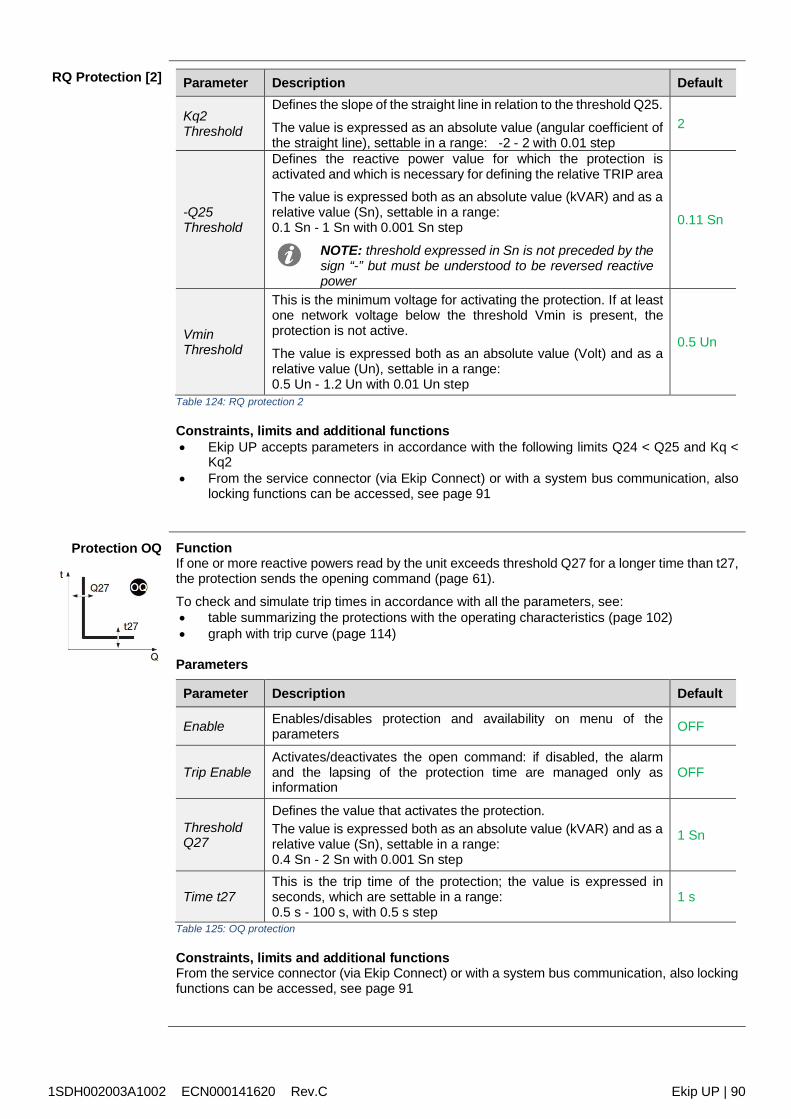
1SDH002003A1002 ECN000141620 Rev.C Ekip UP | 90
RQ Protection [2] Parameter Description Default
Kq2Threshold
Defines the slope of the straight line in relation to the threshold Q25.
The value is expressed as an absolute value (angular coefficient ofthe straight line), settable in a range: -2 - 2 with 0.01 step
2
-Q25Threshold
Defines the reactive power value for which the protection isactivated and which is necessary for defining the relative TRIP areaThe value is expressed both as an absolute value (kVAR) and as arelative value (Sn), settable in a range:0.1 Sn - 1 Sn with 0.001 Sn step
NOTE: threshold expressed in Sn is not preceded by thesign “-” but must be understood to be reversed reactivepower
0.11 Sn
VminThreshold
This is the minimum voltage for activating the protection. If at leastone network voltage below the threshold Vmin is present, theprotection is not active.
The value is expressed both as an absolute value (Volt) and as arelative value (Un), settable in a range:0.5 Un - 1.2 Un with 0.01 Un step
0.5 Un
Table 124: RQ protection 2
Constraints, limits and additional functions Ekip UP accepts parameters in accordance with the following limits Q24 < Q25 and Kq <
Kq2 From the service connector (via Ekip Connect) or with a system bus communication, also
locking functions can be accessed, see page 91
Protection OQ FunctionIf one or more reactive powers read by the unit exceeds threshold Q27 for a longer time than t27,the protection sends the opening command (page 61).
To check and simulate trip times in accordance with all the parameters, see: table summarizing the protections with the operating characteristics (page 102) graph with trip curve (page 114)
Parameters
Parameter Description Default
Enable Enables/disables protection and availability on menu of theparameters OFF
Trip EnableActivates/deactivates the open command: if disabled, the alarmand the lapsing of the protection time are managed only asinformation
OFF
ThresholdQ27
Defines the value that activates the protection.The value is expressed both as an absolute value (kVAR) and as arelative value (Sn), settable in a range:0.4 Sn - 2 Sn with 0.001 Sn step
1 Sn
Time t27This is the trip time of the protection; the value is expressed inseconds, which are settable in a range:0.5 s - 100 s, with 0.5 s step
1 s
Table 125: OQ protection
Constraints, limits and additional functionsFrom the service connector (via Ekip Connect) or with a system bus communication, also lockingfunctions can be accessed, see page 91
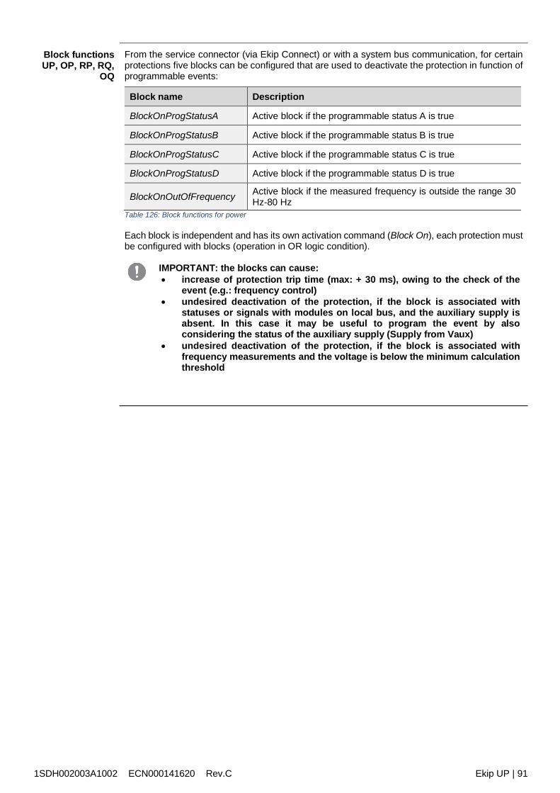
1SDH002003A1002 ECN000141620 Rev.C Ekip UP | 91
Block functionsUP, OP, RP, RQ,
OQ
From the service connector (via Ekip Connect) or with a system bus communication, for certainprotections five blocks can be configured that are used to deactivate the protection in function ofprogrammable events:
Block name Description
BlockOnProgStatusA Active block if the programmable status A is true
BlockOnProgStatusB Active block if the programmable status B is true
BlockOnProgStatusC Active block if the programmable status C is true
BlockOnProgStatusD Active block if the programmable status D is true
BlockOnOutOfFrequency Active block if the measured frequency is outside the range 30Hz-80 Hz
Table 126: Block functions for power
Each block is independent and has its own activation command (Block On), each protection mustbe configured with blocks (operation in OR logic condition).
IMPORTANT: the blocks can cause: increase of protection trip time (max: + 30 ms), owing to the check of the
event (e.g.: frequency control) undesired deactivation of the protection, if the block is associated with
statuses or signals with modules on local bus, and the auxiliary supply isabsent. In this case it may be useful to program the event by alsoconsidering the status of the auxiliary supply (Supply from Vaux)
undesired deactivation of the protection, if the block is associated withfrequency measurements and the voltage is below the minimum calculationthreshold
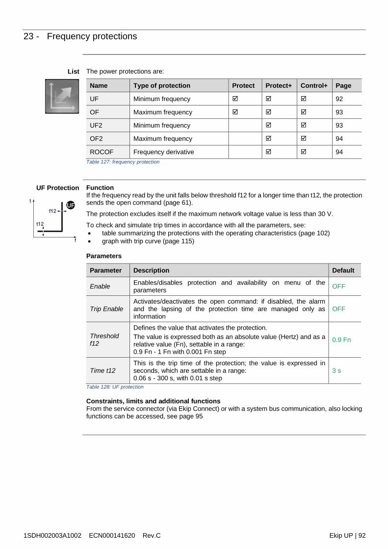
1SDH002003A1002 ECN000141620 Rev.C Ekip UP | 92
23 - Frequency protections
List The power protections are:
Name Type of protection Protect Protect+ Control+ Page
UF Minimum frequency 92
OF Maximum frequency 93
UF2 Minimum frequency 93
OF2 Maximum frequency 94
ROCOF Frequency derivative 94Table 127: frequency protection
UF Protection FunctionIf the frequency read by the unit falls below threshold f12 for a longer time than t12, the protectionsends the open command (page 61).
The protection excludes itself if the maximum network voltage value is less than 30 V.
To check and simulate trip times in accordance with all the parameters, see: table summarizing the protections with the operating characteristics (page 102) graph with trip curve (page 115)
Parameters
Parameter Description Default
Enable Enables/disables protection and availability on menu of theparameters OFF
Trip EnableActivates/deactivates the open command: if disabled, the alarmand the lapsing of the protection time are managed only asinformation
OFF
Thresholdf12
Defines the value that activates the protection.The value is expressed both as an absolute value (Hertz) and as arelative value (Fn), settable in a range:0.9 Fn - 1 Fn with 0.001 Fn step
0.9 Fn
Time t12This is the trip time of the protection; the value is expressed inseconds, which are settable in a range:0.06 s - 300 s, with 0.01 s step
3 s
Table 128: UF protection
Constraints, limits and additional functionsFrom the service connector (via Ekip Connect) or with a system bus communication, also lockingfunctions can be accessed, see page 95
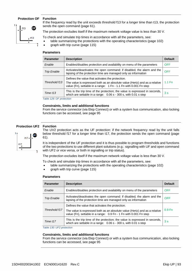
1SDH002003A1002 ECN000141620 Rev.C Ekip UP | 93
Protection OF FunctionIf the frequency read by the unit exceeds threshold f13 for a longer time than t13, the protectionsends the open command (page 61).
The protection excludes itself if the maximum network voltage value is less than 30 V.
To check and simulate trip times in accordance with all the parameters, see: table summarizing the protections with the operating characteristics (page 102) graph with trip curve (page 115)
Parameters
Parameter Description Default
Enable Enables/disables protection and availability on menu of the parameters OFF
Trip Enable Activates/deactivates the open command: if disabled, the alarm and thelapsing of the protection time are managed only as information OFF
Threshold f13Defines the value that activates the protection.The value is expressed both as an absolute value (Hertz) and as a relativevalue (Fn), settable in a range: 1 Fn - 1.1 Fn with 0.001 Fn step
1.1 Fn
Time t13 This is the trip time of the protection; the value is expressed in seconds,which are settable in a range: 0.06 s - 300 s, with 0.01 s step 3 s
Table 129: OF protection
Constraints, limits and additional functionsFrom the service connector (via Ekip Connect) or with a system bus communication, also lockingfunctions can be accessed, see page 95
Protection UF2 FunctionThe UV2 protection acts as the UF protection: if the network frequency read by the unit fallsbelow threshold f17 for a longer time than t17, the protection sends the open command (page61).
It is independent of the UF protection and it is thus possible to program thresholds and functionsof the two protections to use different plant solutions (e.g.: signalling with UF and open commandwith UF2 or vice versa, or both in signalling or trip status).
The protection excludes itself if the maximum network voltage value is less than 30 V.
To check and simulate trip times in accordance with all the parameters, see: table summarizing the protections with the operating characteristics (page 102) graph with trip curve (page 115)
Parameters
Parameter Description Default
Enable Enables/disables protection and availability on menu of the parameters OFF
Trip Enable Activates/deactivates the open command: if disabled, the alarm and thelapsing of the protection time are managed only as information OFF
Threshold f17Defines the value that activates the protection.
The value is expressed both as an absolute value (Hertz) and as a relativevalue (Fn), settable in a range: 0.9 Fn - 1 Fn with 0.001 Fn step
0.9 Fn
Time t17 This is the trip time of the protection; the value is expressed in seconds,which are settable in a range: 0.06 s - 300 s, with 0.01 s step 3 s
Table 130: UF2 protection
Constraints, limits and additional functionsFrom the service connector (via Ekip Connect) or with a system bus communication, also lockingfunctions can be accessed, see page 95
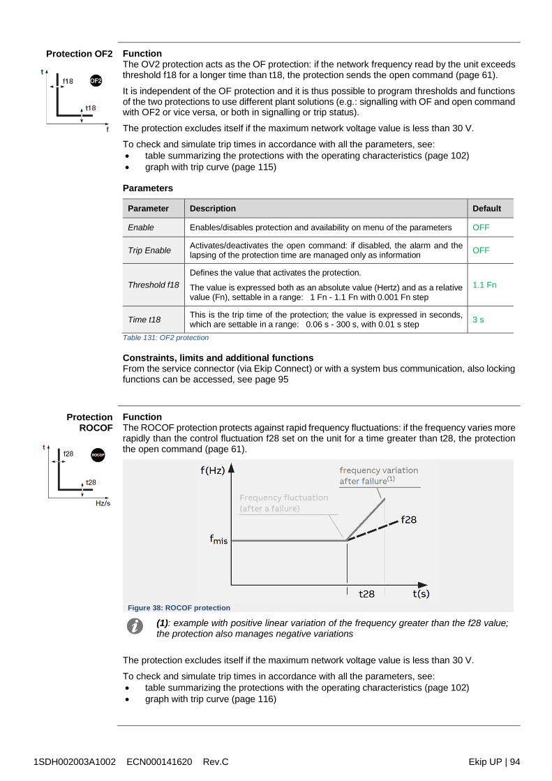
1SDH002003A1002 ECN000141620 Rev.C Ekip UP | 94
Protection OF2 FunctionThe OV2 protection acts as the OF protection: if the network frequency read by the unit exceedsthreshold f18 for a longer time than t18, the protection sends the open command (page 61).
It is independent of the OF protection and it is thus possible to program thresholds and functionsof the two protections to use different plant solutions (e.g.: signalling with OF and open commandwith OF2 or vice versa, or both in signalling or trip status).
The protection excludes itself if the maximum network voltage value is less than 30 V.
To check and simulate trip times in accordance with all the parameters, see: table summarizing the protections with the operating characteristics (page 102) graph with trip curve (page 115)
Parameters
Parameter Description Default
Enable Enables/disables protection and availability on menu of the parameters OFF
Trip Enable Activates/deactivates the open command: if disabled, the alarm and thelapsing of the protection time are managed only as information OFF
Threshold f18Defines the value that activates the protection.
The value is expressed both as an absolute value (Hertz) and as a relativevalue (Fn), settable in a range: 1 Fn - 1.1 Fn with 0.001 Fn step
1.1 Fn
Time t18 This is the trip time of the protection; the value is expressed in seconds,which are settable in a range: 0.06 s - 300 s, with 0.01 s step 3 s
Table 131: OF2 protection
Constraints, limits and additional functionsFrom the service connector (via Ekip Connect) or with a system bus communication, also lockingfunctions can be accessed, see page 95
ProtectionROCOF
FunctionThe ROCOF protection protects against rapid frequency fluctuations: if the frequency varies morerapidly than the control fluctuation f28 set on the unit for a time greater than t28, the protectionthe open command (page 61).
Figure 38: ROCOF protection
(1): example with positive linear variation of the frequency greater than the f28 value;the protection also manages negative variations
The protection excludes itself if the maximum network voltage value is less than 30 V.
To check and simulate trip times in accordance with all the parameters, see: table summarizing the protections with the operating characteristics (page 102) graph with trip curve (page 116)
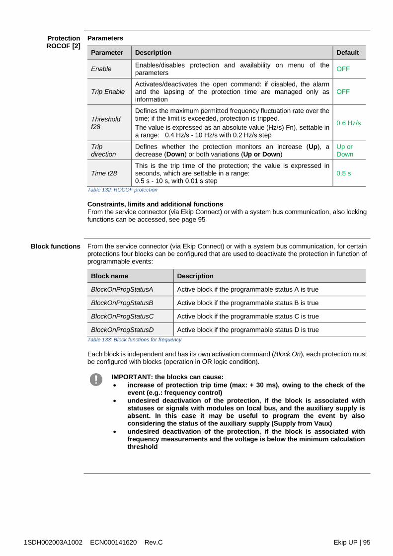
1SDH002003A1002 ECN000141620 Rev.C Ekip UP | 95
ProtectionROCOF [2]
Parameters
Parameter Description Default
Enable Enables/disables protection and availability on menu of theparameters OFF
Trip EnableActivates/deactivates the open command: if disabled, the alarmand the lapsing of the protection time are managed only asinformation
OFF
Thresholdf28
Defines the maximum permitted frequency fluctuation rate over thetime; if the limit is exceeded, protection is tripped.The value is expressed as an absolute value (Hz/s) Fn), settable ina range: 0.4 Hz/s - 10 Hz/s with 0.2 Hz/s step
0.6 Hz/s
Tripdirection
Defines whether the protection monitors an increase (Up), adecrease (Down) or both variations (Up or Down)
Up orDown
Time t28This is the trip time of the protection; the value is expressed inseconds, which are settable in a range:0.5 s - 10 s, with 0.01 s step
0.5 s
Table 132: ROCOF protection
Constraints, limits and additional functionsFrom the service connector (via Ekip Connect) or with a system bus communication, also lockingfunctions can be accessed, see page 95
Block functions From the service connector (via Ekip Connect) or with a system bus communication, for certainprotections four blocks can be configured that are used to deactivate the protection in function ofprogrammable events:
Block name Description
BlockOnProgStatusA Active block if the programmable status A is true
BlockOnProgStatusB Active block if the programmable status B is true
BlockOnProgStatusC Active block if the programmable status C is true
BlockOnProgStatusD Active block if the programmable status D is trueTable 133: Block functions for frequency
Each block is independent and has its own activation command (Block On), each protection mustbe configured with blocks (operation in OR logic condition).
IMPORTANT: the blocks can cause: increase of protection trip time (max: + 30 ms), owing to the check of the
event (e.g.: frequency control) undesired deactivation of the protection, if the block is associated with
statuses or signals with modules on local bus, and the auxiliary supply isabsent. In this case it may be useful to program the event by alsoconsidering the status of the auxiliary supply (Supply from Vaux)
undesired deactivation of the protection, if the block is associated withfrequency measurements and the voltage is below the minimum calculationthreshold
1SDH002003A1002 ECN000141620 Rev.C Ekip UP | 96
24 - Other protections
Hardware Trip Hardware Trip, available in the Settings - Digital Unit menu (page 40), protects from connectionerrors inside Ekip UP.
If enabled, if one or more of these events is detected: Disconnected current sensors (phase, or external if enabled) Disconnected rating plug. Internal unit problems.
The alarm is shown and an open command is sent.
IMPORTANT: the protection is tripped if the error states persist for more than asecond
HarmonicDistortion
Enables an alarm to be activated in the event of distorted waveforms.
In the Measurements menu the protection can be enabled (page 39): if enabled, an alarm alertingto peak factors above 2.1 is triggered.
IMPORTANT: the protection does not manage the trip but only the signal
Protection T The protection T protects from anomalous temperatures recorded by unit.
Is always active and has two statuses according to temperature read:
Status Temperature range Ekip UP actions
Warning -25 < t < -20 or 70 < t < 85 Display switched off; Warning LED ON @ 0.5 Hz
Alarm t < -25 or t > 85 Display switched off; Alarm and Warning LED ON @ 2 HzTable 134: T protection
The parameter Trip Enable, in the Settings - Digital Unit menu (page 40) can be enabled tomanage an open command in the event of alarm.
Cos φ The protection trips when the total Cos φ value falls below the set threshold.
The total cos φ is calculated as a ratio between total active power and total apparent power;
ParametersThe parameters are available in the Advanced - Signals menu (page 38):
Parameter Description Default
Enable Activates/deactivates protection and availability of protection threshold onmenu OFF
Threshold Defines the value that activates the protection; it is settable in a range:0.5 - 0.95 with 0.01 step 0.9
Table 135: Cos φ protection
AdaptiveProtection
The function enables two different protection configurations to be obtained as alternatives to oneanother to manage the set change with programmable events.
In the Settings menu (page 40), it is possible to activate the function
Parameter Description Default
Enable Activates/deactivates the function OFF
Default set Defines the main set of protections and the secondary set of protections(which is activated in the presence of the programmed event). Set A
In the Advanced - Functions menu, the event can be programmed that caused the set change(from default to secondary), see the chapter Programmable commands (page 97).Table 136: adaptive protection
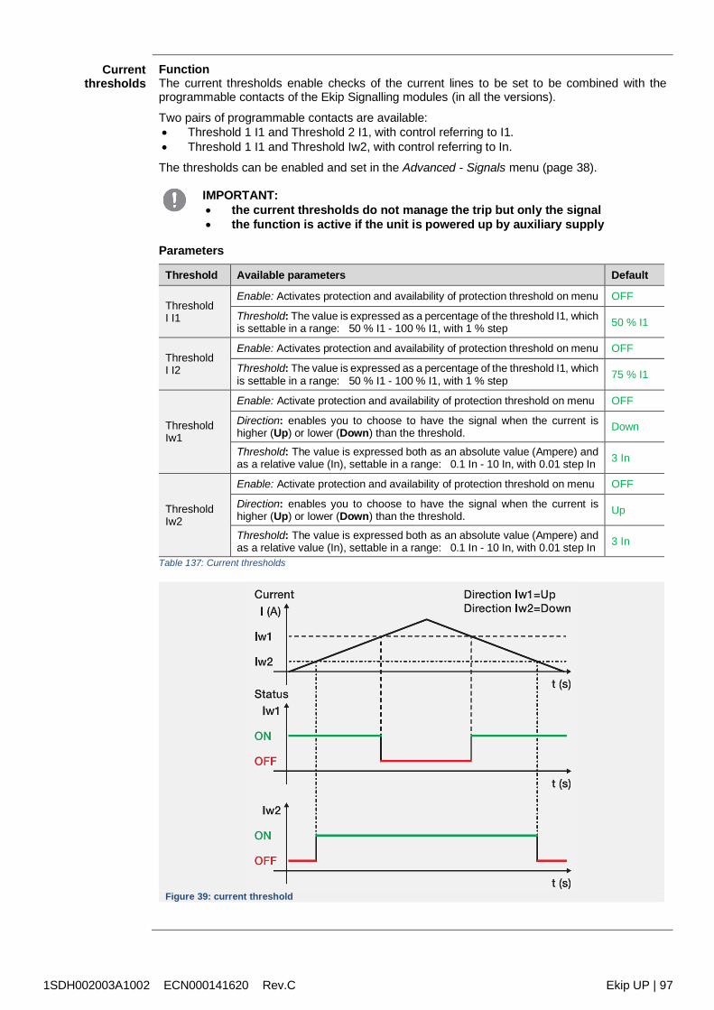
1SDH002003A1002 ECN000141620 Rev.C Ekip UP | 97
Currentthresholds
FunctionThe current thresholds enable checks of the current lines to be set to be combined with theprogrammable contacts of the Ekip Signalling modules (in all the versions).
Two pairs of programmable contacts are available: Threshold 1 I1 and Threshold 2 I1, with control referring to I1. Threshold 1 I1 and Threshold Iw2, with control referring to In.
The thresholds can be enabled and set in the Advanced - Signals menu (page 38).
IMPORTANT: the current thresholds do not manage the trip but only the signal the function is active if the unit is powered up by auxiliary supply
Parameters
Threshold Available parameters Default
ThresholdI I1
Enable: Activates protection and availability of protection threshold on menu OFF
Threshold: The value is expressed as a percentage of the threshold I1, whichis settable in a range: 50 % I1 - 100 % I1, with 1 % step 50 % I1
ThresholdI I2
Enable: Activates protection and availability of protection threshold on menu OFF
Threshold: The value is expressed as a percentage of the threshold I1, whichis settable in a range: 50 % I1 - 100 % I1, with 1 % step 75 % I1
ThresholdIw1
Enable: Activate protection and availability of protection threshold on menu OFF
Direction: enables you to choose to have the signal when the current ishigher (Up) or lower (Down) than the threshold. Down
Threshold: The value is expressed both as an absolute value (Ampere) andas a relative value (In), settable in a range: 0.1 In - 10 In, with 0.01 step In 3 In
ThresholdIw2
Enable: Activate protection and availability of protection threshold on menu OFF
Direction: enables you to choose to have the signal when the current ishigher (Up) or lower (Down) than the threshold. Up
Threshold: The value is expressed both as an absolute value (Ampere) andas a relative value (In), settable in a range: 0.1 In - 10 In, with 0.01 step In 3 In
Table 137: Current thresholds
Figure 39: current threshold
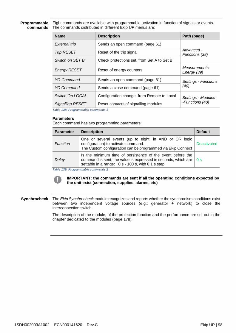
1SDH002003A1002 ECN000141620 Rev.C Ekip UP | 98
Programmablecommands
Eight commands are available with programmable activation in function of signals or events.The commands distributed in different Ekip UP menus are:
Name Description Path (page)
External trip Sends an open command (page 61)Advanced -Functions (38)Trip RESET Reset of the trip signal
Switch on SET B Check protections set, from Set A to Set B
Energy RESET Reset of energy counters Measurements-Energy (39)
YO Command Sends an open command (page 61) Settings - Functions(40)YC Command Sends a close command (page 61)
Switch On LOCAL Configuration change, from Remote to Local Settings - Modules-Functions (40)Signalling RESET Reset contacts of signalling modules
Table 138: Programmable commands 1
ParametersEach command has two programming parameters:
Parameter Description Default
FunctionOne or several events (up to eight, in AND or OR logicconfiguration) to activate command.The Custom configuration can be programmed via Ekip Connect
Deactivated
DelayIs the minimum time of persistence of the event before thecommand is sent; the value is expressed in seconds, which aresettable in a range: 0 s - 100 s, with 0.1 s step
0 s
Table 139: Programmable commands 2
IMPORTANT: the commands are sent if all the operating conditions expected bythe unit exist (connection, supplies, alarms, etc)
Synchrocheck The Ekip Synchrocheck module recognizes and reports whether the synchronism conditions existbetween two independent voltage sources (e.g.: generator + network) to close theinterconnection switch.
The description of the module, of the protection function and the performance are set out in thechapter dedicated to the modules (page 178).
1SDH002003A1002 ECN000141620 Rev.C Ekip UP | 99
25 - Logic Selectivity
Logic Selectivity -Presentation
The Zone Selectivity via Bus Link is indicated as Logic Selectivity.The Logic Selectivity can be actuated for a maximum of 12 of the 15 actors that can be associatedwith Ekip UP via Bus link (see Ekip Link module, page 165).
ParametersFor each protection for which it is desired to activate Zone Selectivity, the available protectionparameter to enable the function must be set.Then, in addition to these parameters, also Selectivity time is activated for the setting.
For the rest, Zone Selectivity can be set only by the Ekip Connect software.
NOTE: all the following parameters and configurations are available via Ekip Connectwith Ekip Link module connected and switched on.
Logic Selectivity -Setting
Certain parameters can be configured in the Ekip Link Configuration page:- selection of selectivity type: hardware or mixed (hardware and logic)- entry of the IP address of each actor present; entry of the address enables the
configuration parameters and status indicators to be displayed in the various pages- the function must be enabled for each actor associated with Ekip UP via Link Bus and
for which logic selectivity must be actuated (the Actor Selectivity parameter must begiven value: True)
Selectivity masks are available in the Ekip Link Advanced Selectivity page for each actor present:the mask allows the protections of the actors (S, G, D-Forward, D-Backward, S2) that activatethe selectivity input of Ekip UP to be selected (example: actor 1, protection mask S= S2:selectivity S of Ekip UP will be active in the presence of signals S2 of actor 1).In this configuration if for protection S the function is enabled and is in alarm status, the S/D-Forward hardware lock output signal is activated and the S logic selectivity bit is activated. Onthe basis of the lock signals: if the S/D-Forward hardware lock input signal and the logic selectivity bits S2 and Gext of
the actor 1 are not active, the open command is sent in accordance with the selectivity setfor the protection S
if the S/D-Forward hardware lock input signal is active and mixed selectivity is selected andthe logic selectivity bits S2 or Gext of the actor 1 are active, the wait time is the same asthe trip time of the protection S (and the open command is sent only if the protection S isstill in alarm status after this time has elapsed)
NOTE: the output and input logic selectivity bits are those in the data packet shared by the
unit via Bus link the S/D-Forward (G/D-Backward) hardware output is activated only if the S or D-
Forward (G or D-Backward) protections are in alarm status, and the S/D-Forward(G/D-Backward) hardware input acts as a lock only for the S and D-Forward (Gand D-Backward) protections, regardless of whether only hardware or mixedselectivity has been selected.
IMPORTANT: if only hardware selectivity has been selected, the input logicselectivity bits are ignored but output logic selectivity bits are activated
Selectivity masksRemote Programmable States A and B are also included in the selectivity masks: these twoparameters, which are available in the Ekip Link Configuration page, enable the event (orcombination of several events) and reference actor that activates the selectivity input to beselected.
Two further states are available, C and D, but they cannot be configured for Zone Selectivity. Allfour programmable states are used for the Programmable Logic function (see Ekip Link moduleon page 165).
NOTA: the Programmable Logic function is independent from that of Zone Selectivity
1SDH002003A1002 ECN000141620 Rev.C Ekip UP | 100
Logic Selectivity -Repetition
The Repeat Configuration mask parameter is available in the Ekip Link Advanced selectivitypage; it enables the selection of protections whose logic selectivity bit, if present on the input,must be propagated regardless of the status of the protection on the current unit.
NOTE: the parameter only acts on the selectivity bits. It does not involve the outputs
Logic Selectivity -Diagnosis
In the presence of both hardware and logic Selectivity, the diagnosis highlights any errors in thehardware Selectivity cabling by checking its continuity.
The Ekip Link Diagnosis Configuration page allows you to: enable diagnosis, configure theinterval of time between one inspection and the next, select the inputs to be checked for eachactive actor (S/D_Forward, G/D_Backward).
Then: the hardware inputs are checked at regular intervals if, in Ekip UP, the input of an actor is configured for diagnosis (e.g. input S of actor 3) and
this input is not active when the test is performed, the actor stimulates its output (e.g. actor3 activates output S) for a short time: Ekip UP considers the test result to be positive if itreceives the signal correctly at its input, otherwise it will signal error
the diagnosis check will not be performed if the hw input is active: if the input configured fordiagnosis is active when the test is performed, diagnosis check will not be performed and theDetection state parameter in the Ekip Link Status page will indicate: Unknown
Logic Selectivity– errors and
inconsistencies
Regardless of the diagnosis, if a hardware input is active and none of the logic selectivity bits ofthe associated actors is active, a line inconsistency for this input is reported on the Ekip LinkStatus page.
NOTE: in order to check line inconsistency, all the actors associated with the unitare checked, including the actors whose function has not been enabled (theActor Selectivity parameter has not been assigned the value: True)
A line error (detected by the diagnosis) indicates a possible cabling error (e.g.: physicaldisconnection):
the hardware selectivity can then be disabled by not cabling the lock outputs and theinputs and not enabling the diagnosis (disabled by default)
A line inconsistency (regardless of the diagnosis) indicates a possible configuration error (e.g.: ahardware input of the Ekip UP is linked to the hardware output of a device that is not associatedvia Bus link, or of an actor whose function has not been enabled).
to prevent a line inconsistency being reported, the devices whose hardware outputs areconnected to the hardware inputs of Ekip UP must also be connected to the Bus link andbe associated with Ekip UP whereas it is not necessary for their function to be enabled(it is not necessary for the Actor Selectivity parameter to be assigned the value: true)
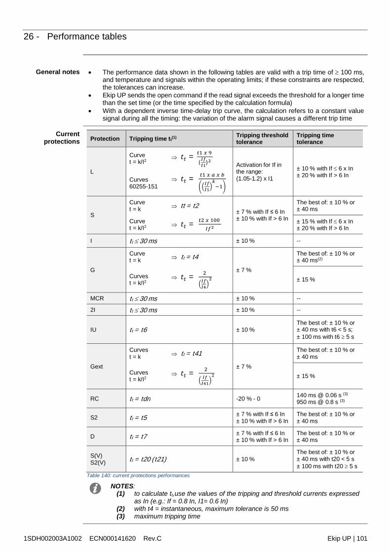
1SDH002003A1002 ECN000141620 Rev.C Ekip UP | 101
26 - Performance tables
General notes The performance data shown in the following tables are valid with a trip time of 100 ms,and temperature and signals within the operating limits; if these constraints are respected,the tolerances can increase.
Ekip UP sends the open command if the read signal exceeds the threshold for a longer timethan the set time (or the time specified by the calculation formula)
With a dependent inverse time-delay trip curve, the calculation refers to a constant valuesignal during all the timing: the variation of the alarm signal causes a different trip time
Currentprotections Protection Tripping time tt(1) Tripping threshold
toleranceTripping timetolerance
L
Curvet = k/I2
𝑡𝑡 = 𝑡1 𝑥 9
(𝐼𝑓𝐼1)2 Activation for If inthe range:(1.05-1.2) x I1
± 10 % with If 6 x In± 20 % with If > 6 In
Curves60255-151
𝑡𝑡 = 𝑡1 𝑥 𝑎 𝑥 𝑏𝐼𝑓𝐼1
𝑘−1
S
Curvet = k tt = t2
± 7 % with If ≤ 6 In± 10 % with If > 6 In
The best of: ± 10 % or± 40 ms
Curvet = k/I2 𝑡𝑡 = 𝑡2 𝑥 100
𝐼𝑓2± 15 % with If 6 x In± 20 % with If > 6 In
I tt 30 ms ± 10 % --
G
Curvet = k tt = t4
± 7 %
The best of: ± 10 % or± 40 ms(2)
Curvest = k/I2
𝑡𝑡 = 2 𝐼𝑓𝐼4
2 ± 15 %
MCR tt 30 ms ± 10 % --
2I tt 30 ms ± 10 % --
IU tt = t6 ± 10 %The best of: ± 10 % or± 40 ms with t6 < 5 s;± 100 ms with t6 5 s
Gext
Curvest = k tt = t41
± 7 %
The best of: ± 10 % or± 40 ms
Curvest = k/I2
𝑡𝑡 = 2 𝐼𝑓𝐼41
2 ± 15 %
RC tt = tdn -20 % - 0 140 ms @ 0.06 s (3)
950 ms @ 0.8 s (3)
S2 tt = t5 ± 7 % with If ≤ 6 In± 10 % with If > 6 In
The best of: ± 10 % or± 40 ms
D tt = t7 ± 7 % with If ≤ 6 In± 10 % with If > 6 In
The best of: ± 10 % or± 40 ms
S(V)S2(V) tt = t20 (t21) ± 10 %
The best of: ± 10 % or± 40 ms with t20 < 5 s± 100 ms with t20 5 s
Table 140: current protections performances
NOTES:(1) to calculate tt,use the values of the tripping and threshold currents expressed
as In (e.g.: If = 0.8 In, I1= 0.6 In)(2) with t4 = instantaneous, maximum tolerance is 50 ms(3) maximum tripping time
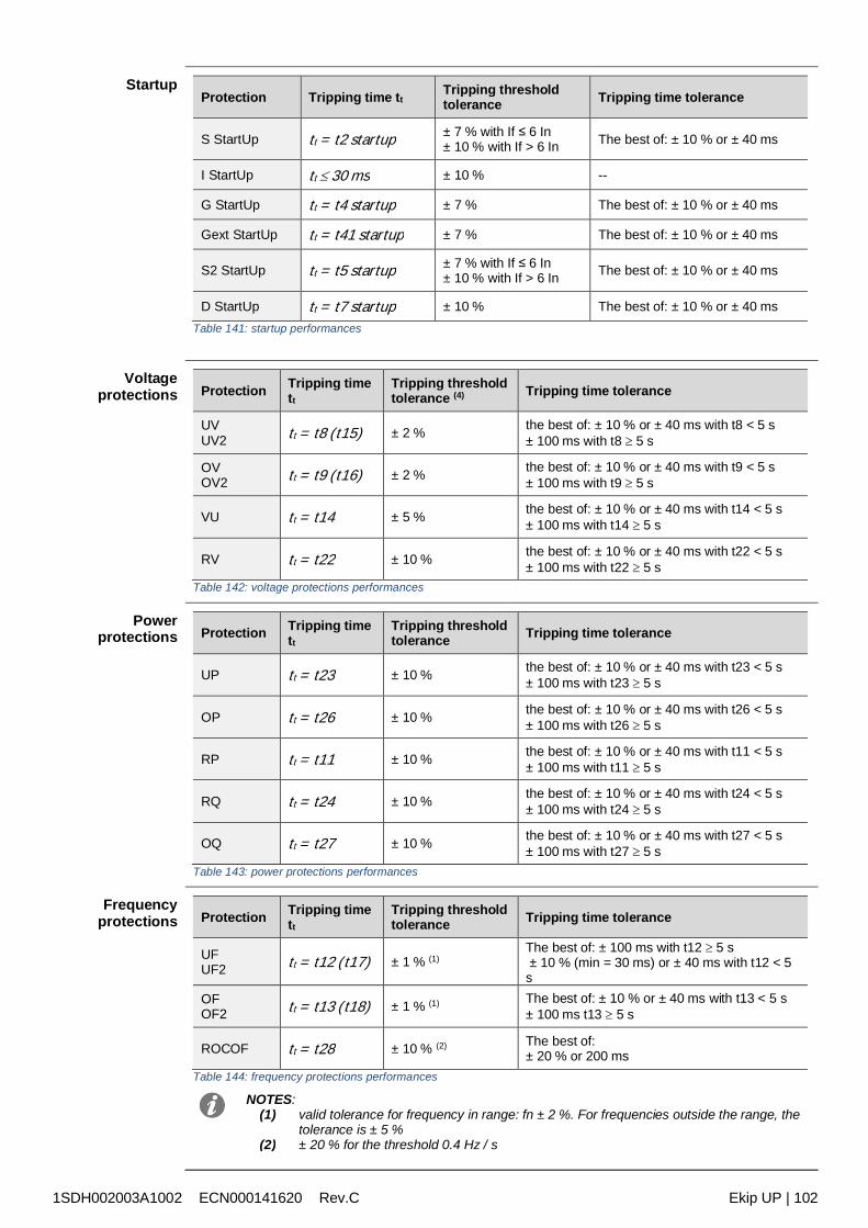
1SDH002003A1002 ECN000141620 Rev.C Ekip UP | 102
StartupProtection Tripping time tt
Tripping thresholdtolerance Tripping time tolerance
S StartUp tt = t2 startup ± 7 % with If ≤ 6 In± 10 % with If > 6 In The best of: ± 10 % or ± 40 ms
I StartUp tt 30 ms ± 10 % --
G StartUp tt = t4 startup ± 7 % The best of: ± 10 % or ± 40 ms
Gext StartUp tt = t41 startup ± 7 % The best of: ± 10 % or ± 40 ms
S2 StartUp tt = t5 startup ± 7 % with If ≤ 6 In± 10 % with If > 6 In The best of: ± 10 % or ± 40 ms
D StartUp tt = t7 startup ± 10 % The best of: ± 10 % or ± 40 msTable 141: startup performances
Voltageprotections Protection Tripping time
tt
Tripping thresholdtolerance (4) Tripping time tolerance
UVUV2 tt = t8 (t15) ± 2 % the best of: ± 10 % or ± 40 ms with t8 < 5 s
± 100 ms with t8 5 s
OVOV2 tt = t9 (t16) ± 2 % the best of: ± 10 % or ± 40 ms with t9 < 5 s
± 100 ms with t9 5 s
VU tt = t14 ± 5 % the best of: ± 10 % or ± 40 ms with t14 < 5 s± 100 ms with t14 5 s
RV tt = t22 ± 10 % the best of: ± 10 % or ± 40 ms with t22 < 5 s± 100 ms with t22 5 s
Table 142: voltage protections performances
Powerprotections Protection Tripping time
tt
Tripping thresholdtolerance Tripping time tolerance
UP tt = t23 ± 10 % the best of: ± 10 % or ± 40 ms with t23 < 5 s± 100 ms with t23 5 s
OP tt = t26 ± 10 % the best of: ± 10 % or ± 40 ms with t26 < 5 s± 100 ms with t26 5 s
RP tt = t11 ± 10 % the best of: ± 10 % or ± 40 ms with t11 < 5 s± 100 ms with t11 5 s
RQ tt = t24 ± 10 % the best of: ± 10 % or ± 40 ms with t24 < 5 s± 100 ms with t24 5 s
OQ tt = t27 ± 10 % the best of: ± 10 % or ± 40 ms with t27 < 5 s± 100 ms with t27 5 s
Table 143: power protections performances
Frequencyprotections Protection Tripping time
tt
Tripping thresholdtolerance Tripping time tolerance
UFUF2 tt = t12 (t17) ± 1 % (1)
The best of: ± 100 ms with t12 5 s ± 10 % (min = 30 ms) or ± 40 ms with t12 < 5s
OFOF2 tt = t13 (t18) ± 1 % (1) The best of: ± 10 % or ± 40 ms with t13 < 5 s
± 100 ms t13 5 s
ROCOF tt = t28 ± 10 % (2) The best of:± 20 % or 200 ms
Table 144: frequency protections performances
NOTES:(1) valid tolerance for frequency in range: fn ± 2 %. For frequencies outside the range, the
tolerance is ± 5 %(2) ± 20 % for the threshold 0.4 Hz / s
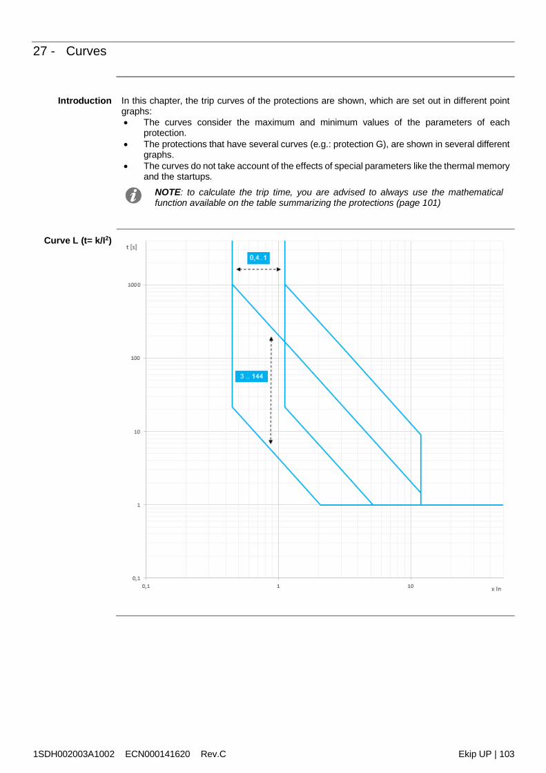
1SDH002003A1002 ECN000141620 Rev.C Ekip UP | 103
27 - Curves
Introduction In this chapter, the trip curves of the protections are shown, which are set out in different pointgraphs: The curves consider the maximum and minimum values of the parameters of each
protection. The protections that have several curves (e.g.: protection G), are shown in several different
graphs. The curves do not take account of the effects of special parameters like the thermal memory
and the startups.NOTE: to calculate the trip time, you are advised to always use the mathematicalfunction available on the table summarizing the protections (page 101)
Curve L (t= k/I2)
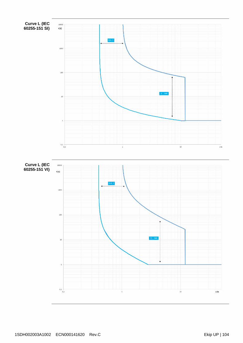
1SDH002003A1002 ECN000141620 Rev.C Ekip UP | 104
Curve L (IEC60255-151 SI)
Curve L (IEC60255-151 VI)
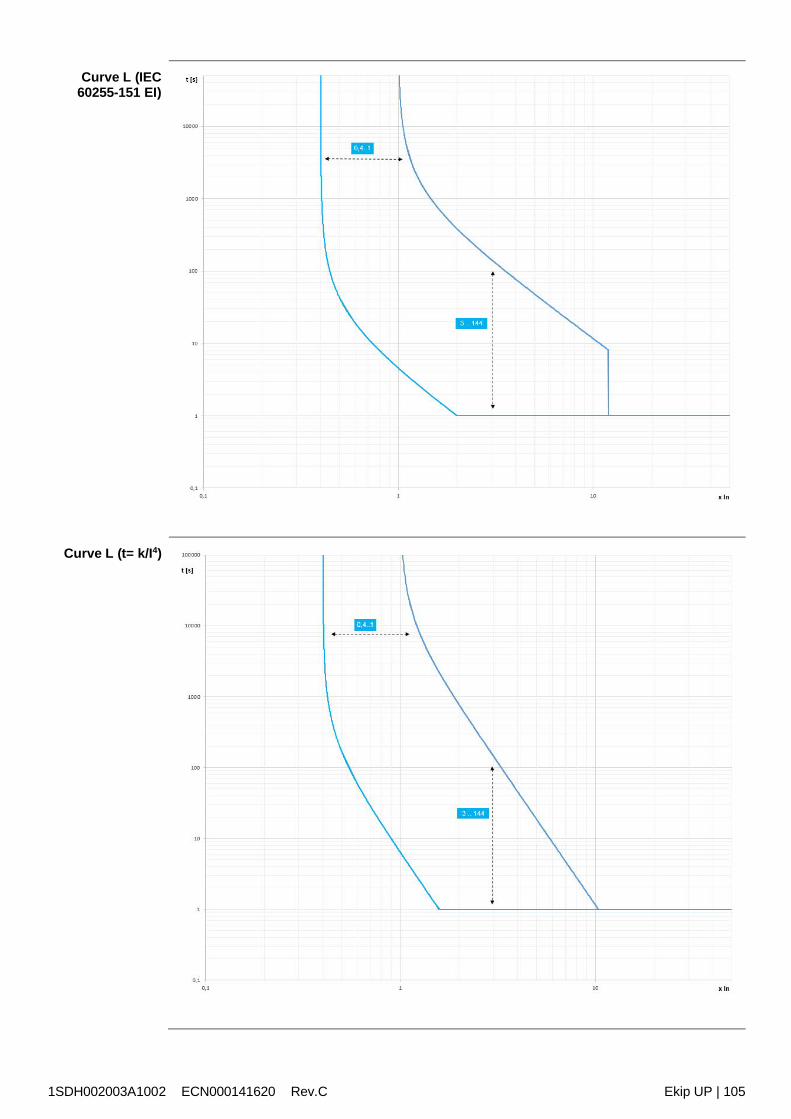
1SDH002003A1002 ECN000141620 Rev.C Ekip UP | 105
Curve L (IEC60255-151 EI)
Curve L (t= k/I4)
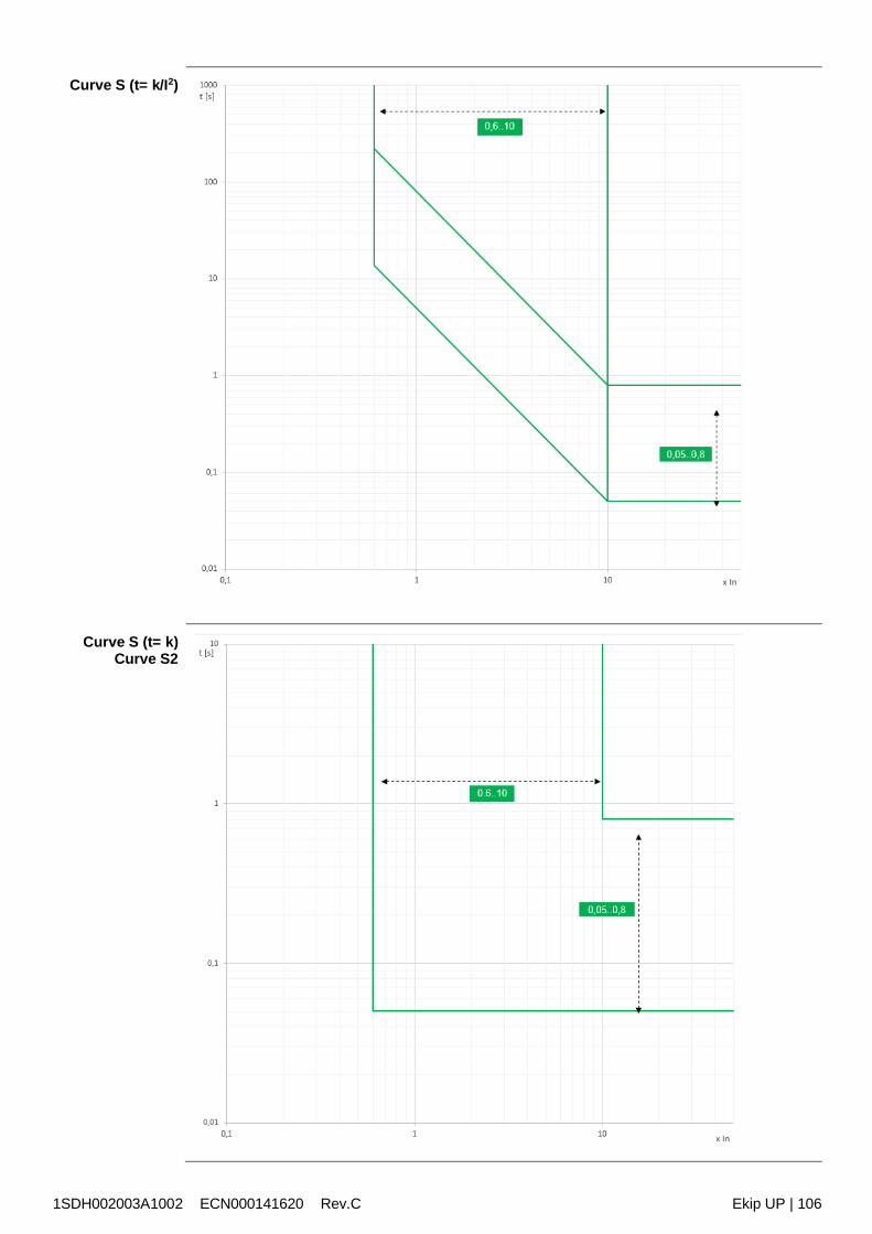
1SDH002003A1002 ECN000141620 Rev.C Ekip UP | 106
Curve S (t= k/I2)
Curve S (t= k)Curve S2
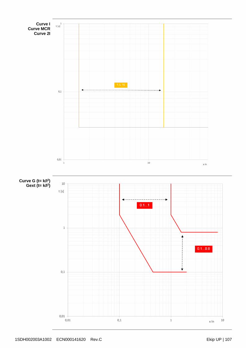
1SDH002003A1002 ECN000141620 Rev.C Ekip UP | 107
Curve ICurve MCR
Curve 2I
Curve G (t= k/I2)Gext (t= k/I2)
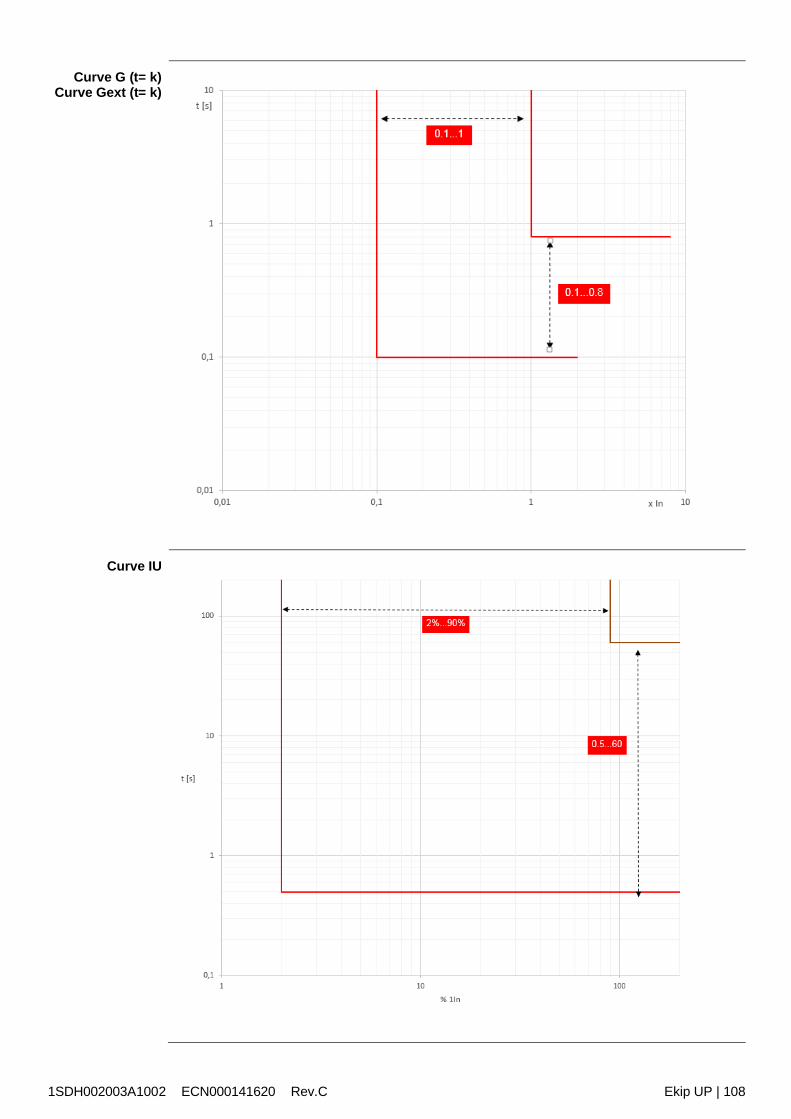
1SDH002003A1002 ECN000141620 Rev.C Ekip UP | 108
Curve G (t= k)Curve Gext (t= k)
Curve IU
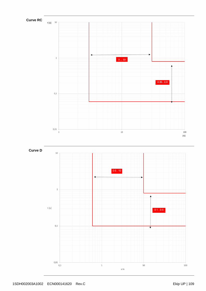
1SDH002003A1002 ECN000141620 Rev.C Ekip UP | 109
Curve RC
Curve D
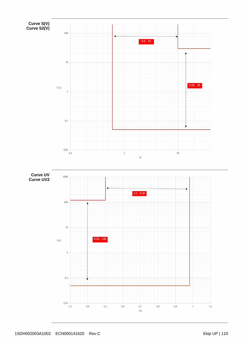
1SDH002003A1002 ECN000141620 Rev.C Ekip UP | 110
Curve S(V)Curve S2(V)
Curve UVCurve UV2
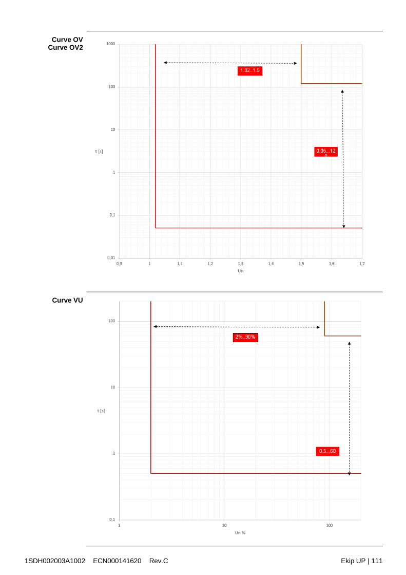
1SDH002003A1002 ECN000141620 Rev.C Ekip UP | 111
Curve OVCurve OV2
Curve VU
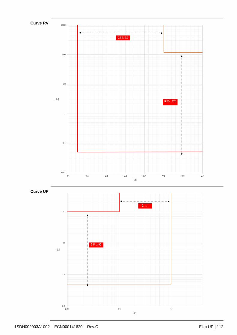
1SDH002003A1002 ECN000141620 Rev.C Ekip UP | 112
Curve RV
Curve UP
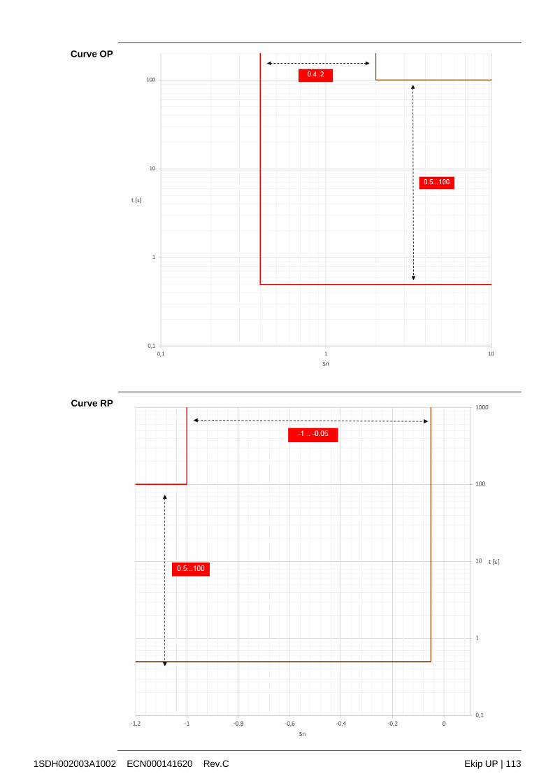
1SDH002003A1002 ECN000141620 Rev.C Ekip UP | 113
Curve OP
Curve RP
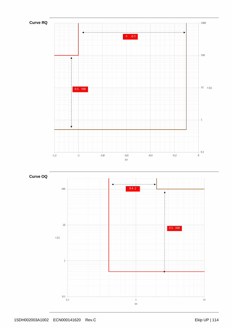
1SDH002003A1002 ECN000141620 Rev.C Ekip UP | 114
Curve RQ
Curve OQ
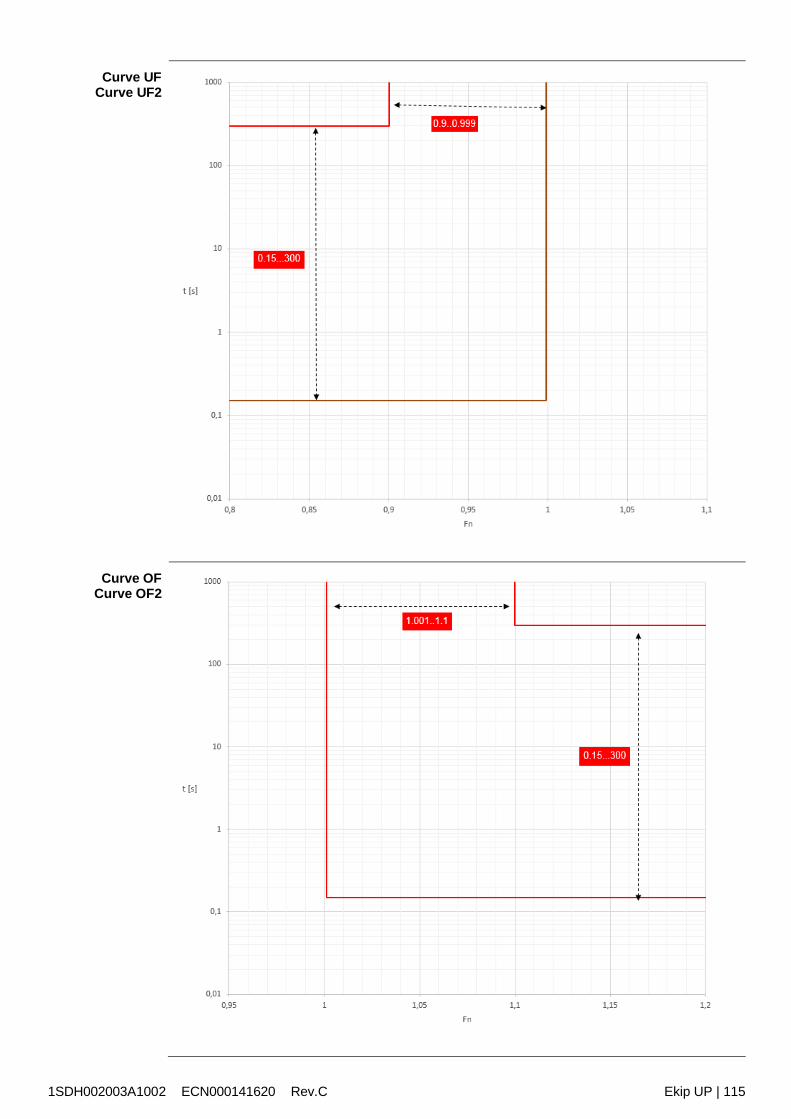
1SDH002003A1002 ECN000141620 Rev.C Ekip UP | 115
Curve UFCurve UF2
Curve OFCurve OF2
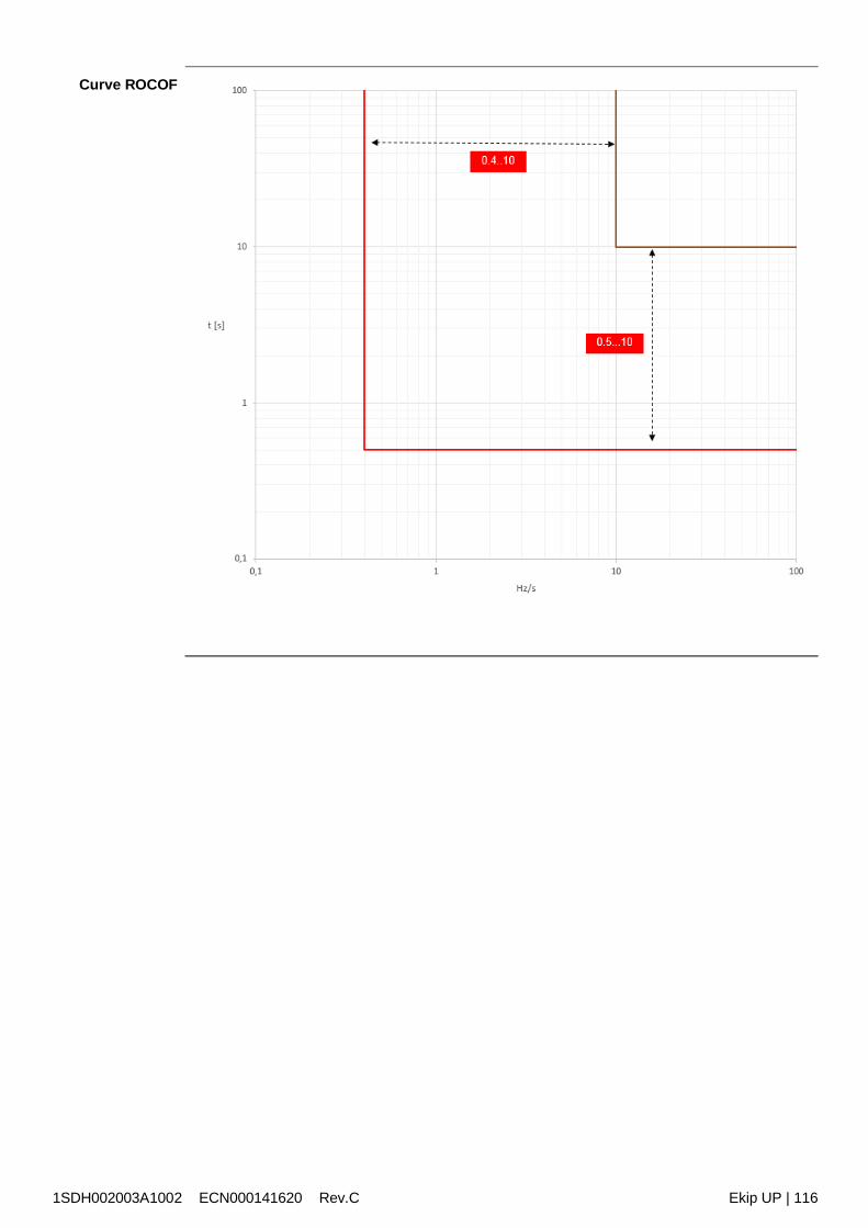
1SDH002003A1002 ECN000141620 Rev.C Ekip UP | 116
Curve ROCOF
1SDH002003A1002 ECN000141620 Rev.C Ekip UP | 117
Control
28 - Power Controller
Presentation The Ekip Power Controller function, available for Ekip UP in the Control and Control+ versions,enables the loads of a plant to be managed in function of power consumption, to limitconsumption and optimize energy efficiency.The purpose of the function is to prevent a given power consumption limit being exceeded by: the cumulative measurement of the energy consumed by the plant of a lapse of time the estimate of the energy consumed at the end of the monitoring periods into which the
electric energy invoicing period is divided the automatic control of the loads: temporary disconnection of the less urgent loads if the
control thresholds are exceeded that derive from the set parameters (power limit andmonitoring period)
automatic recognition of the monitoring periods, on the basis of the unit's inner clock or ofan external synchronization signal, with reset and restart of the energy counters at the startof each period.
More information on the potential of the function are available in the White Paper1SDC007410G0201 “Managing loads with Ekip Power Controller for SACE Emax 2” and in theproduct note 1SDC210110D0201.
Advantages The function allow to: prevents the contractual power limit with the electric power provider being exceeded and
the contractual power and overheads having to be increased to cope with possible spikesand avoid fines
enables the plant to be oversized to avoid the overload protection being tripped provides smart real time management of the loads in response to actual plant consumption
needs at any instant.
The control of the loads based on the energy measurement rather than the instantaneous powerenables power spikes to be tolerated that are greater than the contractual limit if the duration ofthe spikes is such that the average power over the monitoring period does not exceed thecontractual limit.
This is useful because invoicing and possible fines by the power provider are calculated on thebasis of the average power measured at predefined intervals of time, precisely on the basis ofthe highest average power reached during the invoicing period.
Operatingprinciple
A central unit (master), the seat of the function, is linked by cables or a dedicated bus link to theappliances located upstream of the load supply circuits (slave).The slave can be loads or generators. The generators are controlled in the opposite manner tothe loads, i.e. they are connected in the event of high consumption (to activate additional sourcesof energy) and are disconnected in the event of reduced consumption.
The master estimates at regular intervals (monitoring period) the consumed energy; at the endof each period, the master makes certain evaluations:1. if the estimate is in the region of high consumption, a load is disconnected (or a generator is
connected)2. if the estimate is in the region of reduced consumption, a load is connected (or a generator
is disconnected)3. if the estimate is in the region of acceptable consumption, nothing happens.
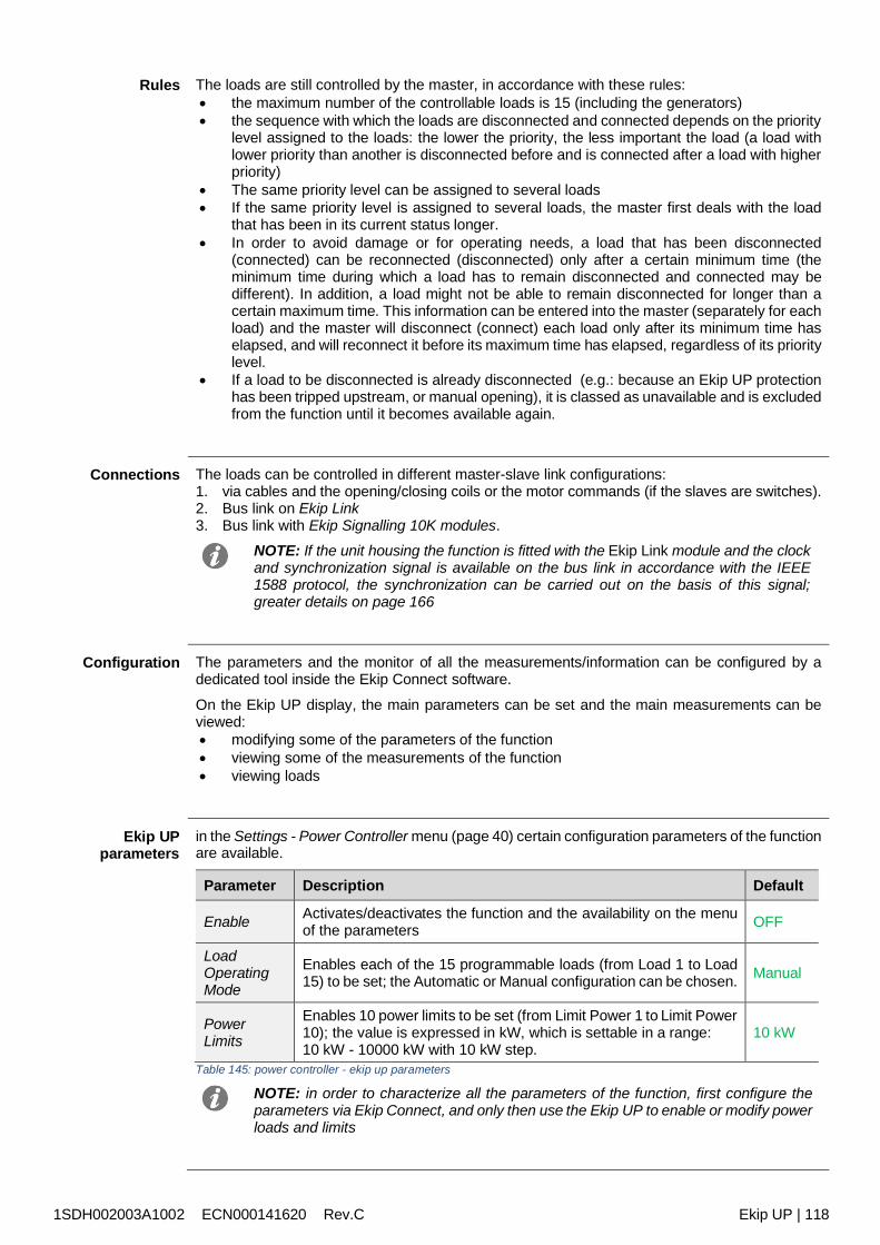
1SDH002003A1002 ECN000141620 Rev.C Ekip UP | 118
Rules The loads are still controlled by the master, in accordance with these rules: the maximum number of the controllable loads is 15 (including the generators) the sequence with which the loads are disconnected and connected depends on the priority
level assigned to the loads: the lower the priority, the less important the load (a load withlower priority than another is disconnected before and is connected after a load with higherpriority)
The same priority level can be assigned to several loads If the same priority level is assigned to several loads, the master first deals with the load
that has been in its current status longer. In order to avoid damage or for operating needs, a load that has been disconnected
(connected) can be reconnected (disconnected) only after a certain minimum time (theminimum time during which a load has to remain disconnected and connected may bedifferent). In addition, a load might not be able to remain disconnected for longer than acertain maximum time. This information can be entered into the master (separately for eachload) and the master will disconnect (connect) each load only after its minimum time haselapsed, and will reconnect it before its maximum time has elapsed, regardless of its prioritylevel.
If a load to be disconnected is already disconnected (e.g.: because an Ekip UP protectionhas been tripped upstream, or manual opening), it is classed as unavailable and is excludedfrom the function until it becomes available again.
Connections The loads can be controlled in different master-slave link configurations:1. via cables and the opening/closing coils or the motor commands (if the slaves are switches).2. Bus link on Ekip Link3. Bus link with Ekip Signalling 10K modules.
NOTE: If the unit housing the function is fitted with the Ekip Link module and the clockand synchronization signal is available on the bus link in accordance with the IEEE1588 protocol, the synchronization can be carried out on the basis of this signal;greater details on page 166
Configuration The parameters and the monitor of all the measurements/information can be configured by adedicated tool inside the Ekip Connect software.
On the Ekip UP display, the main parameters can be set and the main measurements can beviewed: modifying some of the parameters of the function viewing some of the measurements of the function viewing loads
Ekip UPparameters
in the Settings - Power Controller menu (page 40) certain configuration parameters of the functionare available.
Parameter Description Default
Enable Activates/deactivates the function and the availability on the menuof the parameters OFF
LoadOperatingMode
Enables each of the 15 programmable loads (from Load 1 to Load15) to be set; the Automatic or Manual configuration can be chosen. Manual
PowerLimits
Enables 10 power limits to be set (from Limit Power 1 to Limit Power10); the value is expressed in kW, which is settable in a range:10 kW - 10000 kW with 10 kW step.
10 kW
Table 145: power controller - ekip up parameters
NOTE: in order to characterize all the parameters of the function, first configure theparameters via Ekip Connect, and only then use the Ekip UP to enable or modify powerloads and limits
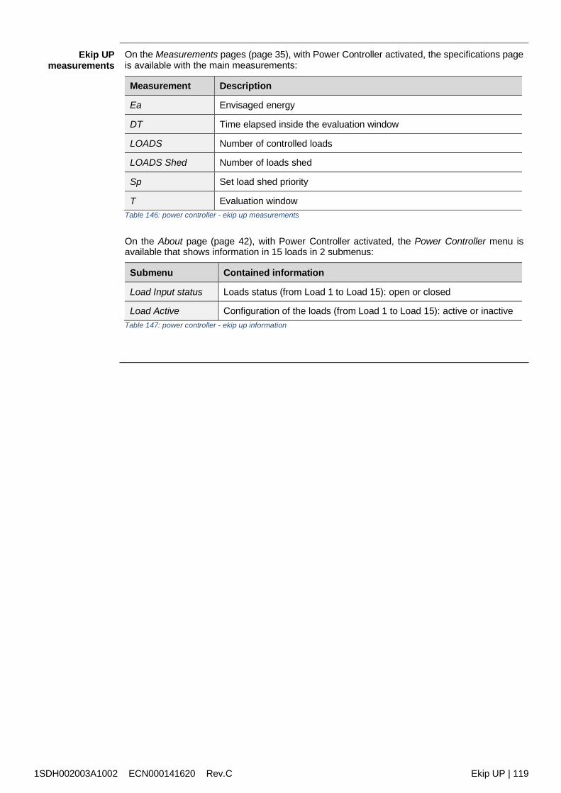
1SDH002003A1002 ECN000141620 Rev.C Ekip UP | 119
Ekip UPmeasurements
On the Measurements pages (page 35), with Power Controller activated, the specifications pageis available with the main measurements:
Measurement Description
Ea Envisaged energy
DT Time elapsed inside the evaluation window
LOADS Number of controlled loads
LOADS Shed Number of loads shed
Sp Set load shed priority
T Evaluation windowTable 146: power controller - ekip up measurements
On the About page (page 42), with Power Controller activated, the Power Controller menu isavailable that shows information in 15 loads in 2 submenus:
Submenu Contained information
Load Input status Loads status (from Load 1 to Load 15): open or closed
Load Active Configuration of the loads (from Load 1 to Load 15): active or inactiveTable 147: power controller - ekip up information
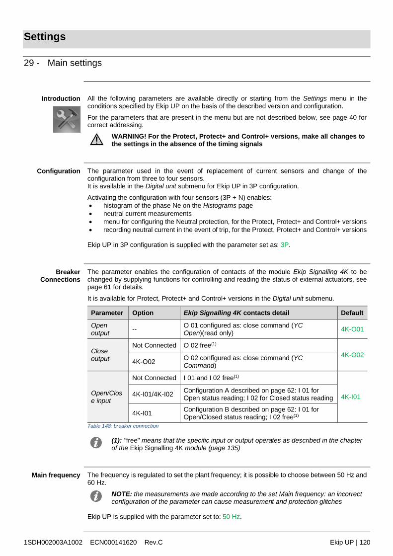
1SDH002003A1002 ECN000141620 Rev.C Ekip UP | 120
Settings
29 - Main settings
Introduction All the following parameters are available directly or starting from the Settings menu in theconditions specified by Ekip UP on the basis of the described version and configuration.
For the parameters that are present in the menu but are not described below, see page 40 forcorrect addressing.
WARNING! For the Protect, Protect+ and Control+ versions, make all changes tothe settings in the absence of the timing signals
Configuration The parameter used in the event of replacement of current sensors and change of theconfiguration from three to four sensors.It is available in the Digital unit submenu for Ekip UP in 3P configuration.
Activating the configuration with four sensors (3P + N) enables: histogram of the phase Ne on the Histograms page neutral current measurements menu for configuring the Neutral protection, for the Protect, Protect+ and Control+ versions recording neutral current in the event of trip, for the Protect, Protect+ and Control+ versions
Ekip UP in 3P configuration is supplied with the parameter set as: 3P.
BreakerConnections
The parameter enables the configuration of contacts of the module Ekip Signalling 4K to bechanged by supplying functions for controlling and reading the status of external actuators, seepage 61 for details.
It is available for Protect, Protect+ and Control+ versions in the Digital unit submenu.
Parameter Option Ekip Signalling 4K contacts detail Default
Openoutput -- O 01 configured as: close command (YC
Open)(read only) 4K-O01
Closeoutput
Not Connected O 02 free(1)
4K-O024K-O02 O 02 configured as: close command (YC
Command)
Open/Close input
Not Connected I 01 and I 02 free(1)
4K-I014K-I01/4K-I02 Configuration A described on page 62: I 01 forOpen status reading; I 02 for Closed status reading
4K-I01 Configuration B described on page 62: I 01 forOpen/Closed status reading; I 02 free(1)
Table 148: breaker connection
(1): "free" means that the specific input or output operates as described in the chapterof the Ekip Signalling 4K module (page 135)
Main frequency The frequency is regulated to set the plant frequency; it is possible to choose between 50 Hz and60 Hz.
NOTE: the measurements are made according to the set Main frequency: an incorrectconfiguration of the parameter can cause measurement and protection glitches
Ekip UP is supplied with the parameter set to: 50 Hz.
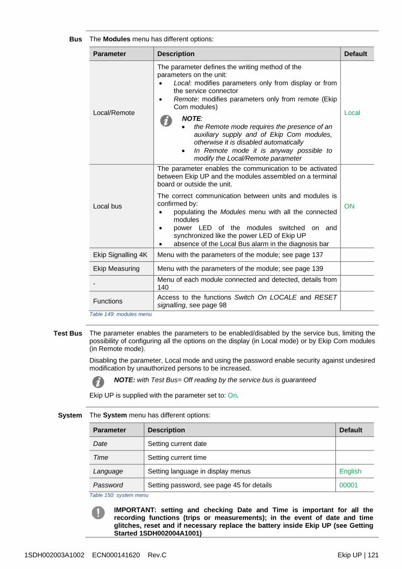
1SDH002003A1002 ECN000141620 Rev.C Ekip UP | 121
Bus The Modules menu has different options:
Parameter Description Default
Local/Remote
The parameter defines the writing method of theparameters on the unit: Local: modifies parameters only from display or from
the service connector Remote: modifies parameters only from remote (Ekip
Com modules)
NOTE: the Remote mode requires the presence of an
auxiliary supply and of Ekip Com modules,otherwise it is disabled automatically
In Remote mode it is anyway possible tomodify the Local/Remote parameter
Local
Local bus
The parameter enables the communication to be activatedbetween Ekip UP and the modules assembled on a terminalboard or outside the unit.
The correct communication between units and modules isconfirmed by: populating the Modules menu with all the connected
modules power LED of the modules switched on and
synchronized like the power LED of Ekip UP absence of the Local Bus alarm in the diagnosis bar
ON
Ekip Signalling 4K Menu with the parameters of the module; see page 137
Ekip Measuring Menu with the parameters of the module; see page 139
- Menu of each module connected and detected, details from140
Functions Access to the functions Switch On LOCALE and RESETsignalling, see page 98
Table 149: modules menu
Test Bus The parameter enables the parameters to be enabled/disabled by the service bus, limiting thepossibility of configuring all the options on the display (in Local mode) or by Ekip Com modules(in Remote mode).
Disabling the parameter, Local mode and using the password enable security against undesiredmodification by unauthorized persons to be increased.
NOTE: with Test Bus= Off reading by the service bus is guaranteed
Ekip UP is supplied with the parameter set to: On.
System The System menu has different options:
Parameter Description Default
Date Setting current date
Time Setting current time
Language Setting language in display menus English
Password Setting password, see page 45 for details 00001Table 150: system menu
IMPORTANT: setting and checking Date and Time is important for all therecording functions (trips or measurements); in the event of date and timeglitches, reset and if necessary replace the battery inside Ekip UP (see GettingStarted 1SDH002004A1001)
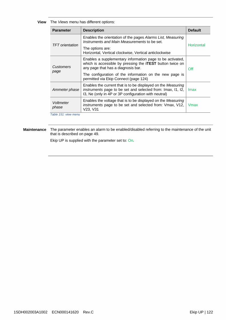
1SDH002003A1002 ECN000141620 Rev.C Ekip UP | 122
View The Views menu has different options:
Parameter Description Default
TFT orientation
Enables the orientation of the pages Alarms List, MeasuringInstruments and Main Measurements to be set.
The options are:Horizontal, Vertical clockwise, Vertical anticlockwise
Horizontal
Customerspage
Enables a supplementary information page to be activated,which is accessible by pressing the iTEST button twice onany page that has a diagnosis bar.
The configuration of the information on the new page ispermitted via Ekip Connect (page 124)
Off
Ammeter phaseEnables the current that is to be displayed on the Measuringinstruments page to be set and selected from: Imax, I1, I2,I3, Ne (only in 4P or 3P configuration with neutral)
Imax
Voltmeterphase
Enables the voltage that is to be displayed on the Measuringinstruments page to be set and selected from: Vmax, V12,V23, V31
Vmax
Table 151: view menu
Maintenance The parameter enables an alarm to be enabled/disabled referring to the maintenance of the unitthat is described on page 49.
Ekip UP is supplied with the parameter set to: On.
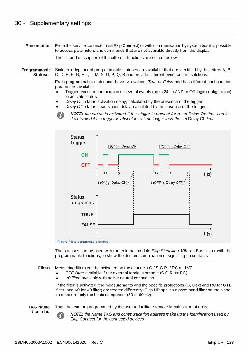
1SDH002003A1002 ECN000141620 Rev.C Ekip UP | 123
30 - Supplementary settings
Presentation From the service connector (via Ekip Connect) or with communication by system bus it is possibleto access parameters and commands that are not available directly from the display.
The list and description of the different functions are set out below.
ProgrammableStatuses
Sixteen independent programmable statuses are available that are identified by the letters A, B,C, D, E, F, G, H, I, L, M, N, O, P, Q, R and provide different event control solutions.
Each programmable status can have two values: True or False and has different configurationparameters available: Trigger: event or combination of several events (up to 24, in AND or OR logic configuration)
to activate status. Delay On: status activation delay, calculated by the presence of the trigger Delay Off: status deactivation delay, calculated by the absence of the trigger
NOTE: the status is activated if the trigger is present for a set Delay On time and isdeactivated if the trigger is absent for a time longer than the set Delay Off time
Figure 40: programmable status
The statuses can be used with the external module Ekip Signalling 10K, on Bus link or with theprogrammable functions, to show the desired combination of signalling on contacts.
Filters Measuring filters can be activated on the channels G / S.G.R. / RC and V0: GTE filter: available if the external toroid is present (S.G.R. or RC). V0 filter: available with active neutral connection
If the filter is activated, the measurements and the specific protections (G, Gext and RC for GTEfilter, and V0 for V0 filter) are treated differently: Ekip UP applies a pass-band filter on the signalto measure only the basic component (50 or 60 Hz).
TAG Name,User data
Tags that can be programmed by the user to facilitate remote identification of units;
NOTE: the Name TAG and communication address make up the identification used byEkip Connect for the connected devices
1SDH002003A1002 ECN000141620 Rev.C Ekip UP | 124
Customers Page Enabling and fields for editing the Customers page (5 information lines) that can be viewed onthe unit display (page 122).
Installation Date of installation of unit
Load Profile Time The counter indicates the time elapsed since the last reset of the energies measurements.It is active and updated in the presence of at least an auxiliary supply or a supply from Ekip T&P.
LED Alive The parameter enables the operation of the power LED of Ekip UP and of all the modulesconnected to the terminal board to be modified; If activated, the power LEDs act as follows: Ekip UP: switches on with 0.5Hz frequency Modules: if there are no communication errors, they synchronize with the Ekip UP LED.
If deactivated, the Power LEDS on the respective devices come on with a fixed light.
Open/CloseRemote Direct
Command
The parameter manages 2 different packets of commands for remote opening and closing: Enabling: commands 7 and 8 valid (direct Open and Close command). Disabled: commands 7 and 8 not valid: in this case, remote opening and closing are
possible using the programmable functions YC COMMAND and YO COMMAND and thecommands Request open switch (28) and Request close switch (29).
Change of doubleset of parameters
always
If activated, it enables the set parameters (Adaptive Protection) to be changed even if timingalarms have been triggered
Default disabled
Repeat S/G HWzone selectivity
If Enabled, the zone selectivity HW signals propagation logic applies in accordance with the tablein the technical log QT1 1SDC007100G0205 .If disabled, the HW selectivity signal is not propagated by Ekip UP
Zone selectivityinput functions
In these section the inputs and some zone selectivity outputs can be configured: Standard: operation of the input and or the output as a standard logic of zone selectivity
(see 1SDC007100G0205 or 1SDC007401G0201); all the selectivity functions are set asStandard.
Customized: the event can be selected that activates the zone selectivity input or output.IMPORTANT: In Customized configuration, the only event that can activate zoneselectivity is the set event and accordingly standard selectivity operation is notactive (change should be made only by expert technical staff)
Glitch Glitch commands 16 to 23 activate the glitch registers. These are used to customizeprogrammable functions or output contacts.
Reset Wizard Reset Wizard: at first startup Ekip UP will show the Wizard window for setting certain unitparameters
1SDH002003A1002 ECN000141620 Rev.C Ekip UP | 125
Test
31 - Test
Presentation On the display the test area can be accessed, in which commands are available for checkingcertain unit functions; all the commands are set out in detail below that are available in the Testmenu (page 41).
Ekip T&P with Ekip Connect has the section Protections Test, to simulate the presence of alarmcurrent or voltage signals and check times and trips (page).
Auto Test The Auto Test command starts an automatic startup sequence of the display and the LEDS toenable the operation of the display and LEDs to be checked.
The sequence consists of the following test phases:1. Screen with message "www.abb.com".2. Display dimming3. Sequence of colouring in red, green, and blue bands with gradual increase of
backlighting.4. Warning LED and Alarm come on for a second.
NOTE: an auxiliary supply is necessary to check the gradual increase of backlighting
Test Protection The menu that is available for the Protect, Protect+ and Control+ versions has two commands:
Command Description Conditions for a correct test
Close Unit Closes the contact 4K O 02 for 0.2 s
Auxiliary supply presentStatus= Open4K O 02 contact configured as CloseOutput (page 120)
Open Unit Closes the contact 4K O 01 for 0.2 s Vaux presentTable 152: Test Protection command
Ekip UP checks that the command has been sent correctly, confirmed by the display window bythe message "Test Executed"; if any conditions are incorrect, the message "Busy" is displayed.
IMPORTANT: after a command, it is the user's responsibility to check that theactuator and information status has actually changed: make sure that the devicesconnected to Ekip UP are connected, supplied and operating correctly before thetest is run
Ekip Signalling4K
The menu is activated in the presence of the Ekip Signalling 4K module and auxiliary supply.
The Auto Test command is available in the module to activate the automatic sequence of testsof the outputs (contacts and LEDs) and performs the following tasks:
1. Reset output contacts (= open) and LED (= off).2. Closure in sequence of all the output contacts with startup of the relative LEDs3. Reset initial conditions
IMPORTANT: for the Protect, Protect+ and Control+ versions, the sequence doesnot include the O 01 output; the output O 02 is also included if configured as aclose command (page 120)
IMPORTANT: the Auto Test command closes the contacts regardless of theconfiguration set by the user: making the devices secure that are connected tothe Ekip Signalling 4K module, checking the correct closure of the contacts andswitch-on of the LEDs are the user's responsibility.
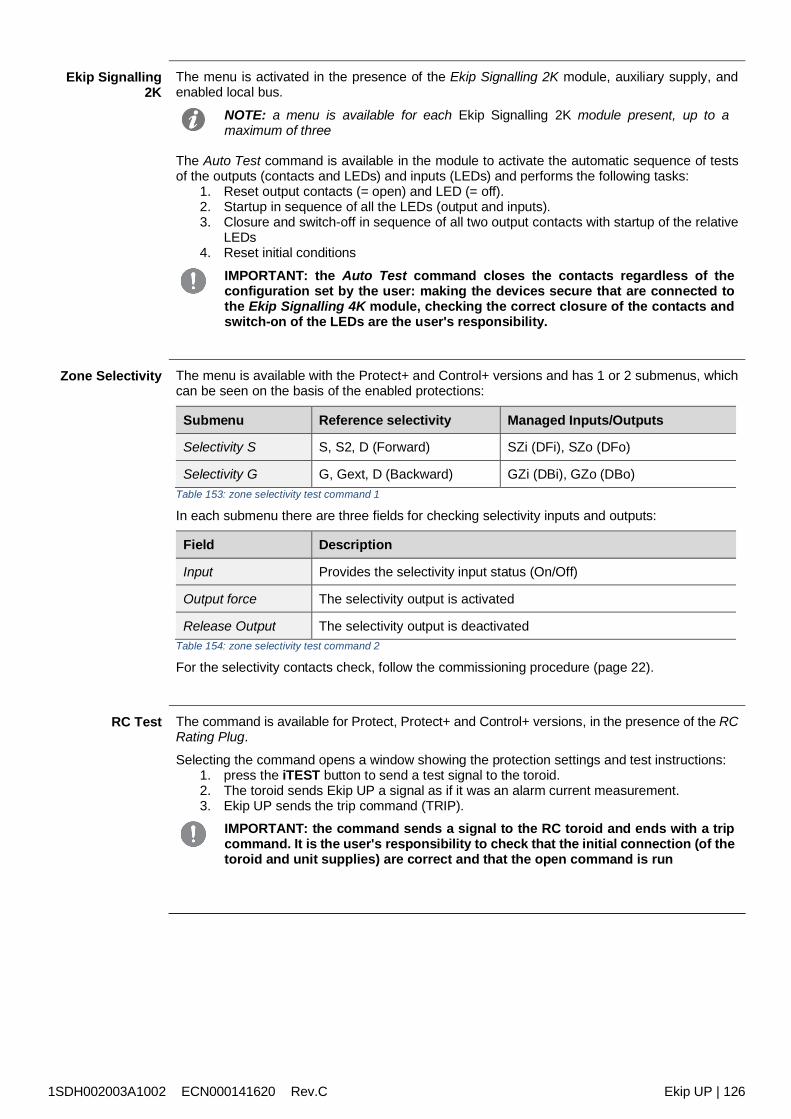
1SDH002003A1002 ECN000141620 Rev.C Ekip UP | 126
Ekip Signalling2K
The menu is activated in the presence of the Ekip Signalling 2K module, auxiliary supply, andenabled local bus.
NOTE: a menu is available for each Ekip Signalling 2K module present, up to amaximum of three
The Auto Test command is available in the module to activate the automatic sequence of testsof the outputs (contacts and LEDs) and inputs (LEDs) and performs the following tasks:
1. Reset output contacts (= open) and LED (= off).2. Startup in sequence of all the LEDs (output and inputs).3. Closure and switch-off in sequence of all two output contacts with startup of the relative
LEDs4. Reset initial conditions
IMPORTANT: the Auto Test command closes the contacts regardless of theconfiguration set by the user: making the devices secure that are connected tothe Ekip Signalling 4K module, checking the correct closure of the contacts andswitch-on of the LEDs are the user's responsibility.
Zone Selectivity The menu is available with the Protect+ and Control+ versions and has 1 or 2 submenus, whichcan be seen on the basis of the enabled protections:
Submenu Reference selectivity Managed Inputs/Outputs
Selectivity S S, S2, D (Forward) SZi (DFi), SZo (DFo)
Selectivity G G, Gext, D (Backward) GZi (DBi), GZo (DBo)Table 153: zone selectivity test command 1
In each submenu there are three fields for checking selectivity inputs and outputs:
Field Description
Input Provides the selectivity input status (On/Off)
Output force The selectivity output is activated
Release Output The selectivity output is deactivatedTable 154: zone selectivity test command 2
For the selectivity contacts check, follow the commissioning procedure (page 22).
RC Test The command is available for Protect, Protect+ and Control+ versions, in the presence of the RCRating Plug.
Selecting the command opens a window showing the protection settings and test instructions:1. press the iTEST button to send a test signal to the toroid.2. The toroid sends Ekip UP a signal as if it was an alarm current measurement.3. Ekip UP sends the trip command (TRIP).
IMPORTANT: the command sends a signal to the RC toroid and ends with a tripcommand. It is the user's responsibility to check that the initial connection (of thetoroid and unit supplies) are correct and that the open command is run
1SDH002003A1002 ECN000141620 Rev.C Ekip UP | 127
Additional functions
32 - Load Shedding
Description The Load Shedding function allows you to manage malfunctions on systems that can work thanksto the energy produced by renewable and local energy sources, in particular a lack of power, e.g.due to a malfunction on the MV voltage side.The function is configurable for the versions Protect, Protect+ and Control+ of Ekip UP andavailable in two versions:
Basic is supplied as default on Ekip UP Adaptive can be purchased with the relative additional package
All the parameters and measurements of the function are available via Ekip Connect; while theEkip UP allows setting and viewing some of them, as noted below.
IMPORTANT: for full details see the Technical Catalog or the function'sdocumentation (see page 13)
Ekip UPparameters
Some function configuration parameters are available In the Settings - Load Shedding menu(page 40).
NOTA : it is advisable to first configure the parameters via Ekip Connect, and only thenoperate on the Ekip UP
Parameter Description Default
Enable Enable/disable the function and the availability of the parameters inthe menu OFF
VersionDisplay of the function version, Basic or AdaptiveE
NOTE: with the Basic version the only parameter availableis Reconnection Timeout
--
Solar SystemPresent Defines if the microgrid includes a solar system (Off/On) Off
Solar rated power
Available with Solar System Present = On, defines the rated power ofyour solar system.The value is expressed in kW, which can be set in a range:100 kW .. 65535 kW with 1 kW steps
100 kW
ATS Defines if the system has an ATS system (Off/On) Off
Generator powerAvailable with ATS = On, it defines the power received from the ATSbranch, which can be set in a range:0 kW (. . . .) .. 10000 kW with 1 kW steps
. . . .
Frequency slope(NOTE)
Defines the variation of real-time frequency that triggers LoadsheddingThe value is expressed in (Hz/s), which can be set in a range:0.6 Hz/s .. 10 Hz/s with 0.2 Hz/s steps
0.6 Hz/s
FW Warning (NOTE)Minimum frequency control threshold that activates Load sheddingThe value is expressed in an absolute value (Hertz), which can be setin a range: 0.9 Fn .. 1.1 Fn with 0.001 Fn steps
1 Fn
ReconnectionTimeout
Defines the time used by Ekip UP between the one load and the next,following the re-closure of the main CB.The value is expressed in (s), which can be set in a range:10 s ..1800 s with 1 s steps
10 s
Table 155: load shedding - parameters
NOTA: Load shedding is activated if the control conditions defined by the Frequencyslope and FW Warning parameters are simultaneously present
1SDH002003A1002 ECN000141620 Rev.C Ekip UP | 128
Ekip UPmeasurements
In the Measurements page, with Load Shedding activated, the specific page with the mainmeasurements is available:
Measurement Description
F Frequency measured
Fn Rated frequency of Ekip UP
LOADS Number of controlled loads
LOADS Shed Number of loads shedTable 156: load shedding - measurements 1
With Power Controller activated, the Load Shedding menu is available in the Information page(page 42), and it provides information on the 15 loads in 2 submenus:
Submenu Information included
Load Input Status Load status (from Load 1 to Load 15): open or closed
Active load Load configuration (from Load 1 to Load 15): active or inactiveTable 157: load shedding - measurements 2
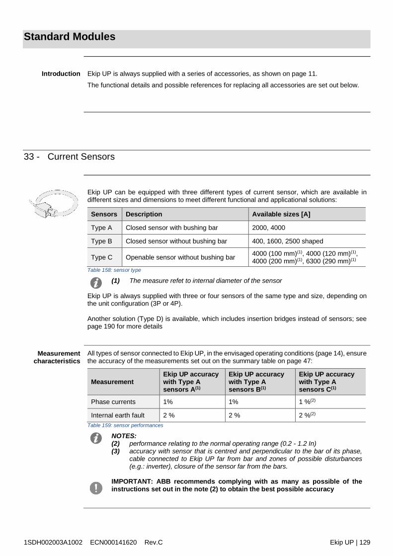
1SDH002003A1002 ECN000141620 Rev.C Ekip UP | 129
Standard Modules
Introduction Ekip UP is always supplied with a series of accessories, as shown on page 11.
The functional details and possible references for replacing all accessories are set out below.
33 - Current Sensors
Ekip UP can be equipped with three different types of current sensor, which are available indifferent sizes and dimensions to meet different functional and applicational solutions:
Sensors Description Available sizes [A]
Type A Closed sensor with bushing bar 2000, 4000
Type B Closed sensor without bushing bar 400, 1600, 2500 shaped
Type C Openable sensor without bushing bar 4000 (100 mm)(1), 4000 (120 mm)(1),4000 (200 mm)(1), 6300 (290 mm)(1)
Table 158: sensor type
(1) The measure refet to internal diameter of the sensor
Ekip UP is always supplied with three or four sensors of the same type and size, depending onthe unit configuration (3P or 4P).
Another solution (Type D) is available, which includes insertion bridges instead of sensors; seepage 190 for more details
Measurementcharacteristics
All types of sensor connected to Ekip UP, in the envisaged operating conditions (page 14), ensurethe accuracy of the measurements set out on the summary table on page 47:
MeasurementEkip UP accuracywith Type Asensors A(1)
Ekip UP accuracywith Type Asensors B(1)
Ekip UP accuracywith Type Asensors C(1)
Phase currents 1% 1% 1 %(2)
Internal earth fault 2 % 2 % 2 %(2)
Table 159: sensor performances
NOTES:(2) performance relating to the normal operating range (0.2 - 1.2 In)(3) accuracy with sensor that is centred and perpendicular to the bar of its phase,
cable connected to Ekip UP far from bar and zones of possible disturbances(e.g.: inverter), closure of the sensor far from the bars.
IMPORTANT: ABB recommends complying with as many as possible of theinstructions set out in the note (2) to obtain the best possible accuracy
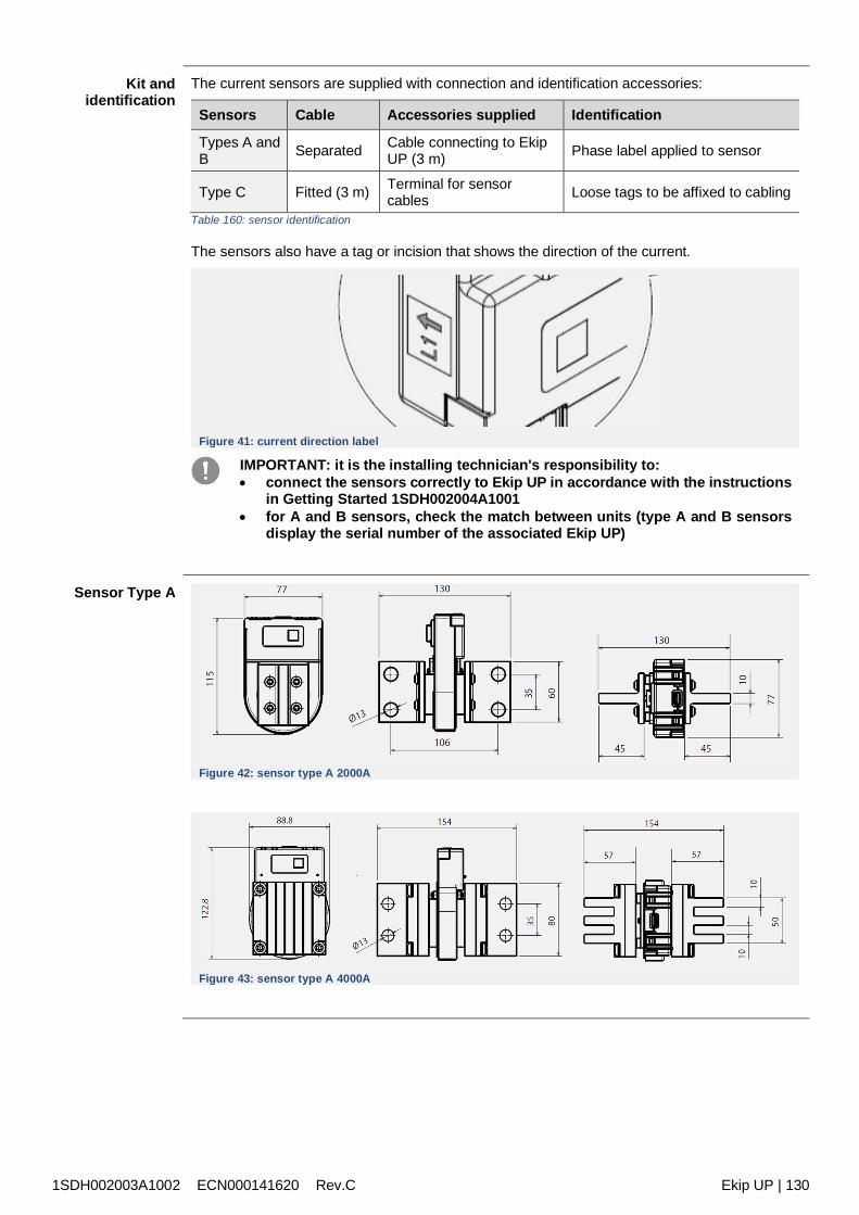
1SDH002003A1002 ECN000141620 Rev.C Ekip UP | 130
Kit andidentification
The current sensors are supplied with connection and identification accessories:
Sensors Cable Accessories supplied Identification
Types A andB Separated Cable connecting to Ekip
UP (3 m) Phase label applied to sensor
Type C Fitted (3 m) Terminal for sensorcables Loose tags to be affixed to cabling
Table 160: sensor identification
The sensors also have a tag or incision that shows the direction of the current.
Figure 41: current direction label
IMPORTANT: it is the installing technician's responsibility to: connect the sensors correctly to Ekip UP in accordance with the instructions
in Getting Started 1SDH002004A1001 for A and B sensors, check the match between units (type A and B sensors
display the serial number of the associated Ekip UP)
Sensor Type A
Figure 42: sensor type A 2000A
Figure 43: sensor type A 4000A

1SDH002003A1002 ECN000141620 Rev.C Ekip UP | 131
Sensor Type B
Figure 44: sensor type B 400A
Figure 45: sensor type B 1600A
Figure 46: sensor type B shaped
With sensor Type B shaped are allowed: busbars with dimensions up to 30 x 50 mm or 20 x 60 mm cable with maximum diameter 54 mm
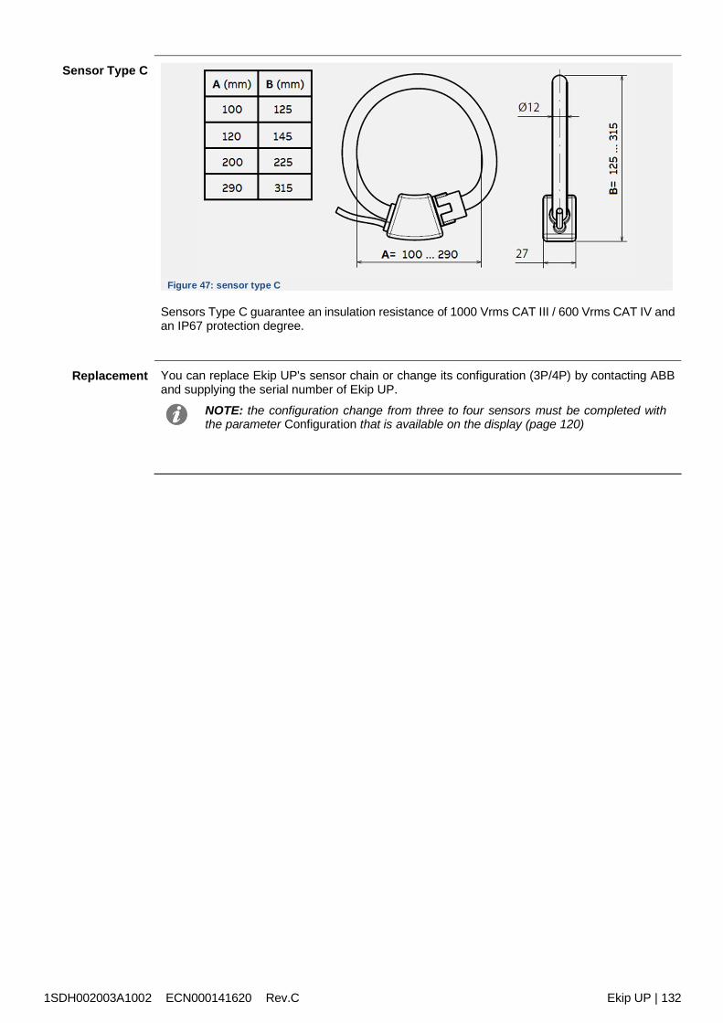
1SDH002003A1002 ECN000141620 Rev.C Ekip UP | 132
Sensor Type C
Figure 47: sensor type C
Sensors Type C guarantee an insulation resistance of 1000 Vrms CAT III / 600 Vrms CAT IV andan IP67 protection degree.
Replacement You can replace Ekip UP's sensor chain or change its configuration (3P/4P) by contacting ABBand supplying the serial number of Ekip UP.
NOTE: the configuration change from three to four sensors must be completed withthe parameter Configuration that is available on the display (page 120)
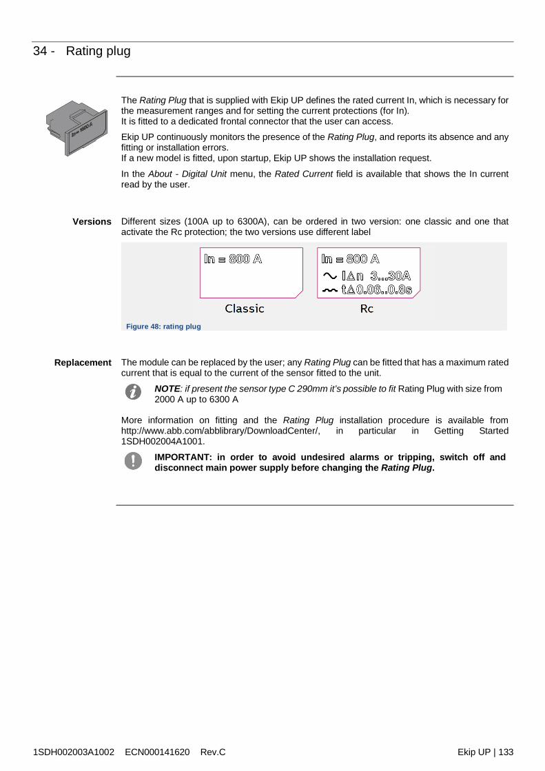
1SDH002003A1002 ECN000141620 Rev.C Ekip UP | 133
34 - Rating plug
The Rating Plug that is supplied with Ekip UP defines the rated current In, which is necessary forthe measurement ranges and for setting the current protections (for In).It is fitted to a dedicated frontal connector that the user can access.Ekip UP continuously monitors the presence of the Rating Plug, and reports its absence and anyfitting or installation errors.If a new model is fitted, upon startup, Ekip UP shows the installation request.
In the About - Digital Unit menu, the Rated Current field is available that shows the In currentread by the user.
Versions Different sizes (100A up to 6300A), can be ordered in two version: one classic and one thatactivate the Rc protection; the two versions use different label
Figure 48: rating plug
Replacement The module can be replaced by the user; any Rating Plug can be fitted that has a maximum ratedcurrent that is equal to the current of the sensor fitted to the unit.
NOTE: if present the sensor type C 290mm it’s possible to fit Rating Plug with size from2000 A up to 6300 A
More information on fitting and the Rating Plug installation procedure is available fromhttp://www.abb.com/abblibrary/DownloadCenter/, in particular in Getting Started1SDH002004A1001.
IMPORTANT: in order to avoid undesired alarms or tripping, switch off anddisconnect main power supply before changing the Rating Plug.
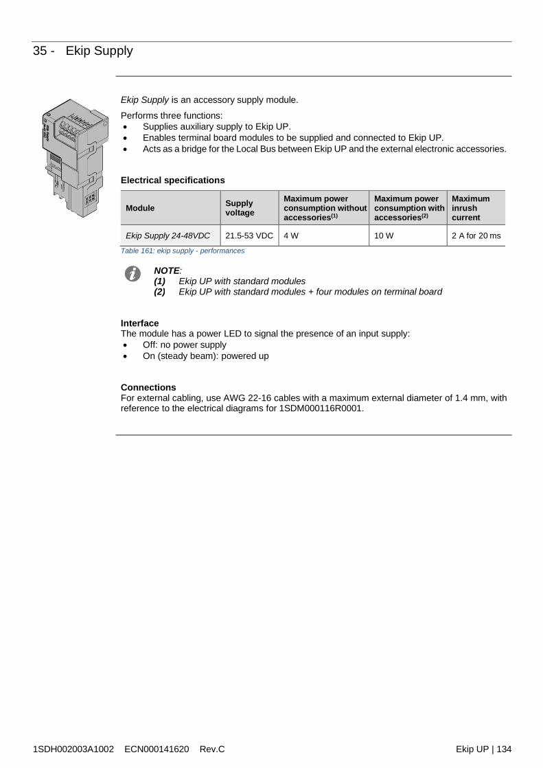
1SDH002003A1002 ECN000141620 Rev.C Ekip UP | 134
35 - Ekip Supply
Ekip Supply is an accessory supply module.
Performs three functions: Supplies auxiliary supply to Ekip UP. Enables terminal board modules to be supplied and connected to Ekip UP. Acts as a bridge for the Local Bus between Ekip UP and the external electronic accessories.
Electrical specifications
Module Supplyvoltage
Maximum powerconsumption withoutaccessories(1)
Maximum powerconsumption withaccessories(2)
Maximuminrushcurrent
Ekip Supply 24-48VDC 21.5-53 VDC 4 W 10 W 2 A for 20 ms
Table 161: ekip supply - performances
NOTE:(1) Ekip UP with standard modules(2) Ekip UP with standard modules + four modules on terminal board
InterfaceThe module has a power LED to signal the presence of an input supply: Off: no power supply On (steady beam): powered up
ConnectionsFor external cabling, use AWG 22-16 cables with a maximum external diameter of 1.4 mm, withreference to the electrical diagrams for 1SDM000116R0001.
1SDH002003A1002 ECN000141620 Rev.C Ekip UP | 135
36 - Ekip Measuring
Introduction Ekip Measuring is an accessory measuring module: Voltage (RMS measurement of the network and voltage phases in the specified cases) Frequency of the voltages Power and energy, using all the measurements of the phase currents
NOTE: the measurement performance levels are disclosed in the Measurementschapter, page 47
The module, if combined with Ekip Synchrocheck, also enables it to be established whether thesynchronism conditions exist between external sockets and external contacts that are necessaryfor closing the synchronism contact (see chapter dedicated to Ekip Synchrocheck, page 178).
Electricalspecifications
The Ekip Measuring operates with Ekip UP powered by auxiliary supply and works in the followingranges:
Component Range
Input network voltage 0 ÷ 760 VAC (692 VAC +10 %)
Input frequency 30 - 80 HzTable 162: ekip measuring - performances
Isolationtransformer
Isolation transformerFor connecting at a network voltage above a rated value of 690 VAC (760 VAC maximum), anisolation transformer must be used that complies with IEC 60255-27 and has the followingcharacteristics:
Characteristics Description
Mechanical
fixing: EN 50022 DIN43880 guide material: self-extinguishing plastic protection level: IP30 electrostatic protection: with screen to be earthed
Electrical
accuracy class: 0.2 performance: 4 VA overload: 20 % permanent insulation: 4 kV between inputs and outputs, 4 kV between
screen and 4 kV outputs between screen and inputs. frequency: 45-66 Hz
Table 163: ekip measuring - transformer
1SDH002003A1002 ECN000141620 Rev.C Ekip UP | 136
Menu If the Ekip Synchrocheck module is detected correctly by Ekip UP the specific configuration areais activated in the Modules - Settings menu.
In this menu, the following parameters can be configured:
Parameter Description Default
Voltmetertransf. Selects the presence or absence of the external transformer Absent
Rated voltageAvailable in absence of transformer, defines rated voltage Un.
The value is expressed as an absolute value (Volt), settable in arange: 100 V - 690 V with variable step
400 V
Primaryvoltage
Available in presence of transformer, defines rated plant voltage.
The value is expressed as an absolute value (Volt), settable in arange: 100 V - 1150 V with variable step
400 V
Secondaryvoltage
Available in presence of transformer, defines the secondaryvoltage of the transformer.
The value is expressed as an absolute value (Volt), settable in arange: 100 V - 230 V with variable step
100 V
PositivePower Flow
Defines the power flow required for protection D (page 74); 2selections available: High Low: the power flow of the actuator connected to
Ekip UP goes from the low to the high terminals (loadconnected low)
Low High: opposite power flow (high connected load)
High Low
Neutralconnection
Available with 3P configuration, enables the presence of externalneutral to be enabled.
NOTE: the presence of the active neutral activates themeasurement of the phase voltages
Absent
Table 164: ekip measuring - menu
Information In the About-Modules menu, the specific menu of the module is available in which the serialnumber and the embodiment of the module are present.
Test For the dielectric test of the module, refer to Getting Started 1SDH002004A1001.
Connections Refer to the electrical diagrams for 1SDM000116R0001 for connecting the external voltagesockets, in all the possible configurations:
three-phase system (with or without transformer) three-phase system with neutral (with or without transformer) three-phase system and residual voltage control three-phase system with transformer and residual voltage control
NOTE: configuration with residual voltage control available with Protect+ and Control+versions
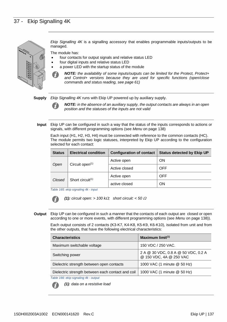
1SDH002003A1002 ECN000141620 Rev.C Ekip UP | 137
37 - Ekip Signalling 4K
Ekip Signalling 4K is a signalling accessory that enables programmable inputs/outputs to bemanaged.
The module has: four contacts for output signals and relative status LED four digital inputs and relative status LED a power LED with the startup status of the module
NOTE: the availability of some inputs/outputs can be limited for the Protect, Protect+and Control+ versions because they are used for specific functions (open/closecommands and status reading, see page 61)
Supply Ekip Signalling 4K runs with Ekip UP powered up by auxiliary supply.
NOTE: in the absence of an auxiliary supply, the output contacts are always in an openposition and the statuses of the inputs are not valid
Input Ekip UP can be configured in such a way that the status of the inputs corresponds to actions orsignals, with different programming options (see Menu on page 138)
Each input (H1, H2, H3, H4) must be connected with reference to the common contacts (HC).The module permits two logic statuses, interpreted by Ekip UP according to the configurationselected for each contact:
Status Electrical condition Configuration of contact Status detected by Ekip UP
Open Circuit open(1)Active open ON
Active closed OFF
Closed Short circuit(1)Active open OFF
active closed ONTable 165: ekip signaling 4k - input
(1): circuit open: > 100 k; short circuit: < 50
Output Ekip UP can be configured in such a manner that the contacts of each output are closed or openaccording to one or more events, with different programming options (see Menu on page 138)).
Each output consists of 2 contacts (K3-K7, K4-K8, K5-K9, K6-K10), isolated from unit and fromthe other outputs, that have the following electrical characteristics:
Characteristics Maximum limit(1)
Maximum switchable voltage 150 VDC / 250 VAC.
Switching power 2 A @ 30 VDC, 0.8 A @ 50 VDC, 0.2 A@ 150 VDC, 4A @ 250 VAC
Dielectric strength between open contacts 1000 VAC (1 minute @ 50 Hz)
Dielectric strength between each contact and coil 1000 VAC (1 minute @ 50 Hz)Table 166: ekip signaling 4k - output
(1): data on a resistive load
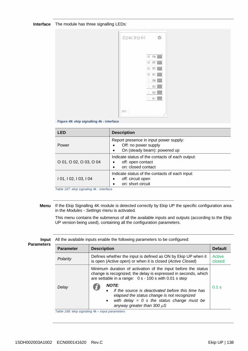
1SDH002003A1002 ECN000141620 Rev.C Ekip UP | 138
Interface The module has three signalling LEDs:
Figure 49: ekip signalling 4k - interface
LED Description
PowerReport presence in input power supply: Off: no power supply On (steady beam): powered up
O 01, O 02, O 03, O 04Indicate status of the contacts of each output: off: open contact on: closed contact
I 01, I 02, I 03, I 04Indicate status of the contacts of each input: off: circuit open on: short circuit
Table 167: ekip signaling 4k - interface
Menu If the Ekip Signalling 4K module is detected correctly by Ekip UP the specific configuration areain the Modules - Settings menu is activated.
This menu contains the submenus of all the available inputs and outputs (according to the EkipUP version being used), containing all the configuration parameters.
InputParameters
All the available inputs enable the following parameters to be configured:
Parameter Description Default
Polarity Defines whether the input is defined as ON by Ekip UP when itis open (Active open) or when it is closed (Active Closed)
Activeclosed
Delay
Minimum duration of activation of the input before the statuschange is recognized; the delay is expressed in seconds, whichare settable in a range: 0 s - 100 s with 0.01 s step
NOTE: if the source is deactivated before this time has
elapsed the status change is not recognized with delay = 0 s the status change must be
anyway greater than 300 S
0.1 s
Table 168: ekip signaling 4k – input parameters
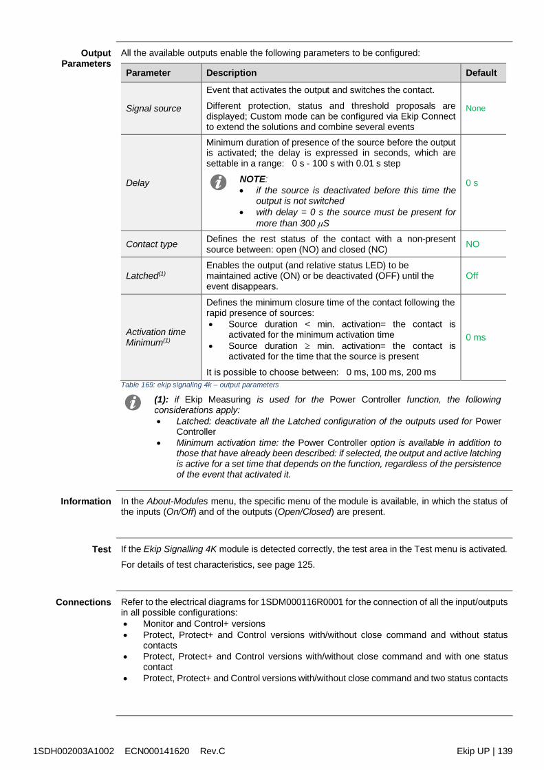
1SDH002003A1002 ECN000141620 Rev.C Ekip UP | 139
OutputParameters
All the available outputs enable the following parameters to be configured:
Parameter Description Default
Signal source
Event that activates the output and switches the contact.
Different protection, status and threshold proposals aredisplayed; Custom mode can be configured via Ekip Connectto extend the solutions and combine several events
None
Delay
Minimum duration of presence of the source before the outputis activated; the delay is expressed in seconds, which aresettable in a range: 0 s - 100 s with 0.01 s step
NOTE: if the source is deactivated before this time the
output is not switched with delay = 0 s the source must be present for
more than 300 S
0 s
Contact type Defines the rest status of the contact with a non-presentsource between: open (NO) and closed (NC) NO
Latched(1)Enables the output (and relative status LED) to bemaintained active (ON) or be deactivated (OFF) until theevent disappears.
Off
Activation timeMinimum(1)
Defines the minimum closure time of the contact following therapid presence of sources: Source duration < min. activation= the contact is
activated for the minimum activation time Source duration min. activation= the contact is
activated for the time that the source is present
It is possible to choose between: 0 ms, 100 ms, 200 ms
0 ms
Table 169: ekip signaling 4k – output parameters
(1): if Ekip Measuring is used for the Power Controller function, the followingconsiderations apply: Latched: deactivate all the Latched configuration of the outputs used for Power
Controller Minimum activation time: the Power Controller option is available in addition to
those that have already been described: if selected, the output and active latchingis active for a set time that depends on the function, regardless of the persistenceof the event that activated it.
Information In the About-Modules menu, the specific menu of the module is available, in which the status ofthe inputs (On/Off) and of the outputs (Open/Closed) are present.
Test If the Ekip Signalling 4K module is detected correctly, the test area in the Test menu is activated.
For details of test characteristics, see page 125.
Connections Refer to the electrical diagrams for 1SDM000116R0001 for the connection of all the input/outputsin all possible configurations: Monitor and Control+ versions Protect, Protect+ and Control versions with/without close command and without status
contacts Protect, Protect+ and Control versions with/without close command and with one status
contact Protect, Protect+ and Control versions with/without close command and two status contacts
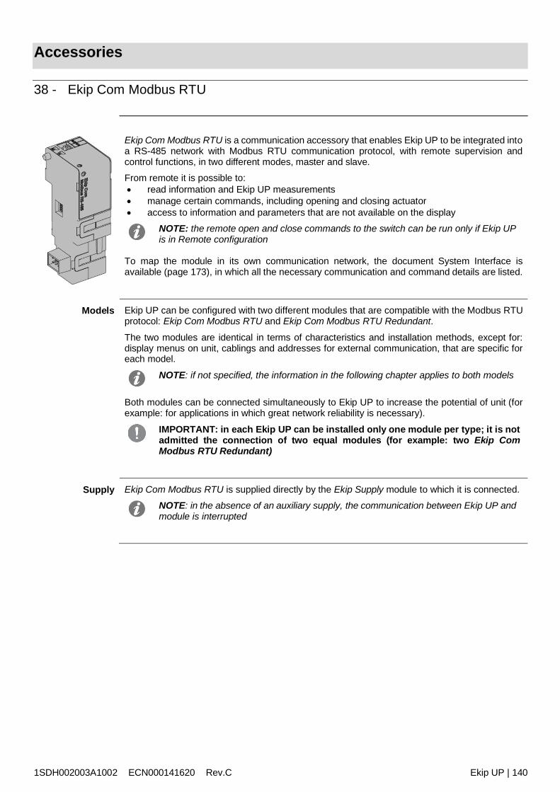
1SDH002003A1002 ECN000141620 Rev.C Ekip UP | 140
Accessories
38 - Ekip Com Modbus RTU
Ekip Com Modbus RTU is a communication accessory that enables Ekip UP to be integrated intoa RS-485 network with Modbus RTU communication protocol, with remote supervision andcontrol functions, in two different modes, master and slave.From remote it is possible to: read information and Ekip UP measurements manage certain commands, including opening and closing actuator access to information and parameters that are not available on the display
NOTE: the remote open and close commands to the switch can be run only if Ekip UPis in Remote configuration
To map the module in its own communication network, the document System Interface isavailable (page 173), in which all the necessary communication and command details are listed.
Models Ekip UP can be configured with two different modules that are compatible with the Modbus RTUprotocol: Ekip Com Modbus RTU and Ekip Com Modbus RTU Redundant.
The two modules are identical in terms of characteristics and installation methods, except for:display menus on unit, cablings and addresses for external communication, that are specific foreach model.
NOTE: if not specified, the information in the following chapter applies to both models
Both modules can be connected simultaneously to Ekip UP to increase the potential of unit (forexample: for applications in which great network reliability is necessary).
IMPORTANT: in each Ekip UP can be installed only one module per type; it is notadmitted the connection of two equal modules (for example: two Ekip ComModbus RTU Redundant)
Supply Ekip Com Modbus RTU is supplied directly by the Ekip Supply module to which it is connected.NOTE: in the absence of an auxiliary supply, the communication between Ekip UP andmodule is interrupted
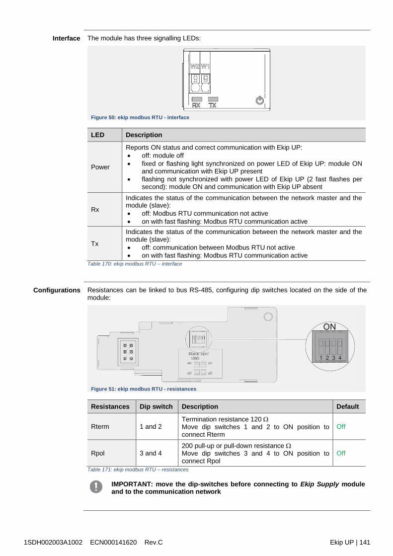
1SDH002003A1002 ECN000141620 Rev.C Ekip UP | 141
Interface The module has three signalling LEDs:
Figure 50: ekip modbus RTU - interface
LED Description
Power
Reports ON status and correct communication with Ekip UP: off: module off fixed or flashing light synchronized on power LED of Ekip UP: module ON
and communication with Ekip UP present flashing not synchronized with power LED of Ekip UP (2 fast flashes per
second): module ON and communication with Ekip UP absent
Rx
Indicates the status of the communication between the network master and themodule (slave): off: Modbus RTU communication not active on with fast flashing: Modbus RTU communication active
Tx
Indicates the status of the communication between the network master and themodule (slave): off: communication between Modbus RTU not active on with fast flashing: Modbus RTU communication active
Table 170: ekip modbus RTU – interface
Configurations Resistances can be linked to bus RS-485, configuring dip switches located on the side of themodule:
Figure 51: ekip modbus RTU - resistances
Resistances Dip switch Description Default
Rterm 1 and 2Termination resistance 120 Move dip switches 1 and 2 to ON position toconnect Rterm
Off
Rpol 3 and 4200 pull-up or pull-down resistance Move dip switches 3 and 4 to ON position toconnect Rpol
Off
Table 171: ekip modbus RTU – resistances
IMPORTANT: move the dip-switches before connecting to Ekip Supply moduleand to the communication network
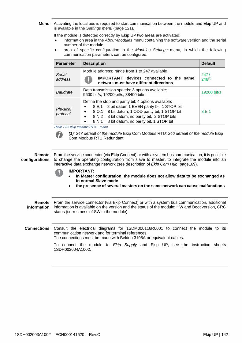
1SDH002003A1002 ECN000141620 Rev.C Ekip UP | 142
Menu Activating the local bus is required to start communication between the module and Ekip UP andis available in the Settings menu (page 121).
If the module is detected correctly by Ekip UP two areas are activated: information area in the About-Modules menu containing the software version and the serial
number of the module area of specific configuration in the Modules Settings menu, in which the following
communication parameters can be configured:
Parameter Description Default
Serialaddress
Module address; range from 1 to 247 available
IMPORTANT: devices connected to the samenetwork must have different directions
247 /246(1)
Baudrate Data transmission speeds: 3 options available:9600 bit/s, 19200 bit/s, 38400 bit/s 19200 bit/s
Physicalprotocol
Define the stop and parity bit; 4 options available: 8,E,1 = 8 bit datum,1 EVEN parity bit, 1 STOP bit 8,O,1 = 8 bit datum, 1 ODD parity bit, 1 STOP bit 8,N,2 = 8 bit datum, no parity bit, 2 STOP bits 8,N,1 = 8 bit datum, no parity bit, 1 STOP bit
8,E,1
Table 172: ekip modbus RTU – menu
(1): 247 default of the module Ekip Com Modbus RTU; 246 default of the module EkipCom Modbus RTU Redundant
Remoteconfigurations
From the service connector (via Ekip Connect) or with a system bus communication, it is possibleto change the operating configuration from slave to master, to integrate the module into aninteractive data exchange network (see description of Ekip Com Hub, page169).
IMPORTANT: In Master configuration, the module does not allow data to be exchanged as
in normal Slave mode the presence of several masters on the same network can cause malfunctions
Remoteinformation
From the service connector (via Ekip Connect) or with a system bus communication, additionalinformation is available on the version and the status of the module: HW and Boot version, CRCstatus (correctness of SW in the module).
Connections Consult the electrical diagrams for 1SDM000116R0001 to connect the module to itscommunication network and for terminal references.The connections must be made with Belden 3105A or equivalent cables.
To connect the module to Ekip Supply and Ekip UP, see the instruction sheets1SDH002004A1002.
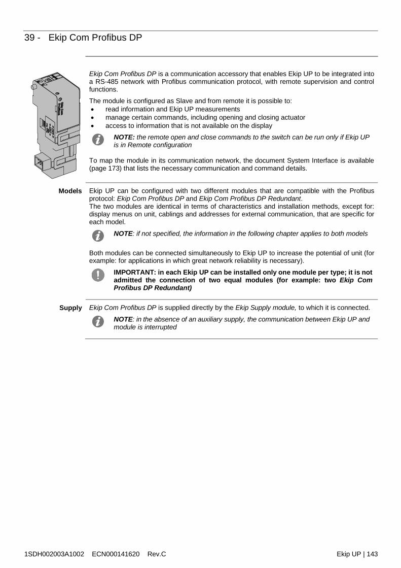
1SDH002003A1002 ECN000141620 Rev.C Ekip UP | 143
39 - Ekip Com Profibus DP
Ekip Com Profibus DP is a communication accessory that enables Ekip UP to be integrated intoa RS-485 network with Profibus communication protocol, with remote supervision and controlfunctions.The module is configured as Slave and from remote it is possible to: read information and Ekip UP measurements manage certain commands, including opening and closing actuator access to information that is not available on the display
NOTE: the remote open and close commands to the switch can be run only if Ekip UPis in Remote configuration
To map the module in its communication network, the document System Interface is available(page 173) that lists the necessary communication and command details.
Models Ekip UP can be configured with two different modules that are compatible with the Profibusprotocol: Ekip Com Profibus DP and Ekip Com Profibus DP Redundant.The two modules are identical in terms of characteristics and installation methods, except for:display menus on unit, cablings and addresses for external communication, that are specific foreach model.
NOTE: if not specified, the information in the following chapter applies to both models
Both modules can be connected simultaneously to Ekip UP to increase the potential of unit (forexample: for applications in which great network reliability is necessary).
IMPORTANT: in each Ekip UP can be installed only one module per type; it is notadmitted the connection of two equal modules (for example: two Ekip ComProfibus DP Redundant)
Supply Ekip Com Profibus DP is supplied directly by the Ekip Supply module, to which it is connected.
NOTE: in the absence of an auxiliary supply, the communication between Ekip UP andmodule is interrupted
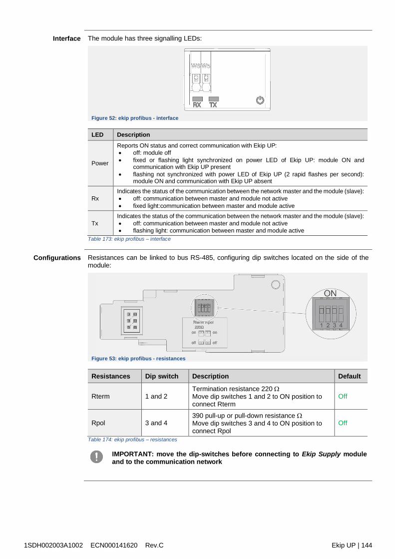
1SDH002003A1002 ECN000141620 Rev.C Ekip UP | 144
Interface The module has three signalling LEDs:
Figure 52: ekip profibus - interface
LED Description
Power
Reports ON status and correct communication with Ekip UP: off: module off fixed or flashing light synchronized on power LED of Ekip UP: module ON and
communication with Ekip UP present flashing not synchronized with power LED of Ekip UP (2 rapid flashes per second):
module ON and communication with Ekip UP absent
RxIndicates the status of the communication between the network master and the module (slave): off: communication between master and module not active fixed light:communication between master and module active
TxIndicates the status of the communication between the network master and the module (slave): off: communication between master and module not active flashing light: communication between master and module active
Table 173: ekip profibus – interface
Configurations Resistances can be linked to bus RS-485, configuring dip switches located on the side of themodule:
Figure 53: ekip profibus - resistances
Resistances Dip switch Description Default
Rterm 1 and 2Termination resistance 220 Move dip switches 1 and 2 to ON position toconnect Rterm
Off
Rpol 3 and 4390 pull-up or pull-down resistance Move dip switches 3 and 4 to ON position toconnect Rpol
Off
Table 174: ekip profibus – resistances
IMPORTANT: move the dip-switches before connecting to Ekip Supply moduleand to the communication network
1SDH002003A1002 ECN000141620 Rev.C Ekip UP | 145
Menu Activating the local bus is required to start communication between the module and Ekip UP andis available in the Settings menu (page 121).
If the module is detected correctly by Ekip UP two areas are activated: information area in the About-Modules menu containing the software version and the serial
number of the module area of specific configuration in the Modules Settings menu, in which the following
communication parameters can be configured:
Parameter Description Default
Serialaddress
Module address; range from 1 to 125 available
IMPORTANT: devices connected to the samenetwork must have different directions
125 /124 (1)
Table 175: ekip profibus – menu
(1): 125 default of the module Ekip Com Profibus DP; 124 default of the module EkipCom Profibus DP Redundant
Remoteinformation
From the service connector (via Ekip Connect) or with a system bus communication, additionalinformation is available on the version and the status of the module: HW and Boot version, CRCstatus (correctness of SW in the module).
Connections Consult the electrical diagrams for 1SDM000116R0001 to connect the module to itscommunication network and for terminal references.The connections must be made with Belden 3079A or equivalent cables.
To connect the module to Ekip Supply and Ekip UP, see the instruction sheets1SDH002004A1002.
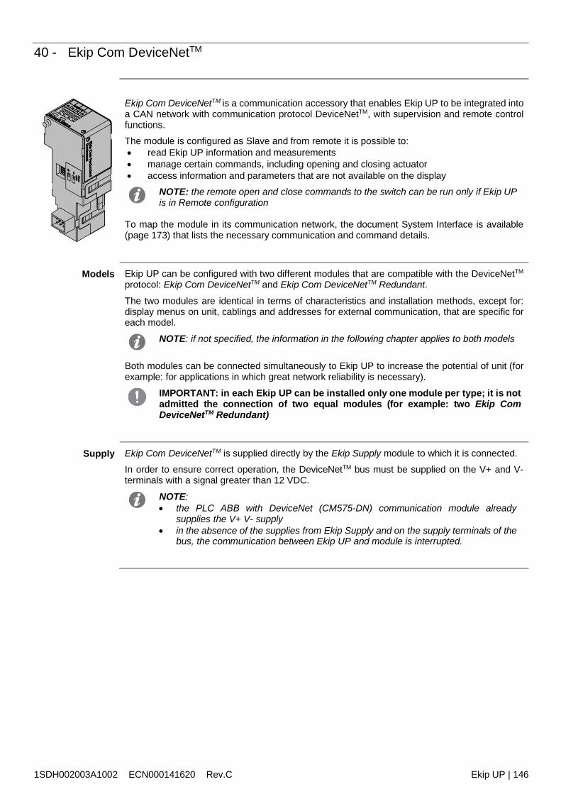
1SDH002003A1002 ECN000141620 Rev.C Ekip UP | 146
40 - Ekip Com DeviceNetTM
Ekip Com DeviceNetTM is a communication accessory that enables Ekip UP to be integrated intoa CAN network with communication protocol DeviceNetTM, with supervision and remote controlfunctions.The module is configured as Slave and from remote it is possible to: read Ekip UP information and measurements manage certain commands, including opening and closing actuator access information and parameters that are not available on the display
NOTE: the remote open and close commands to the switch can be run only if Ekip UPis in Remote configuration
To map the module in its communication network, the document System Interface is available(page 173) that lists the necessary communication and command details.
Models Ekip UP can be configured with two different modules that are compatible with the DeviceNetTM
protocol: Ekip Com DeviceNetTM and Ekip Com DeviceNetTM Redundant.
The two modules are identical in terms of characteristics and installation methods, except for:display menus on unit, cablings and addresses for external communication, that are specific foreach model.
NOTE: if not specified, the information in the following chapter applies to both models
Both modules can be connected simultaneously to Ekip UP to increase the potential of unit (forexample: for applications in which great network reliability is necessary).
IMPORTANT: in each Ekip UP can be installed only one module per type; it is notadmitted the connection of two equal modules (for example: two Ekip ComDeviceNetTM Redundant)
Supply Ekip Com DeviceNetTM is supplied directly by the Ekip Supply module to which it is connected.In order to ensure correct operation, the DeviceNetTM bus must be supplied on the V+ and V-terminals with a signal greater than 12 VDC.
NOTE: the PLC ABB with DeviceNet (CM575-DN) communication module already
supplies the V+ V- supply in the absence of the supplies from Ekip Supply and on the supply terminals of the
bus, the communication between Ekip UP and module is interrupted.
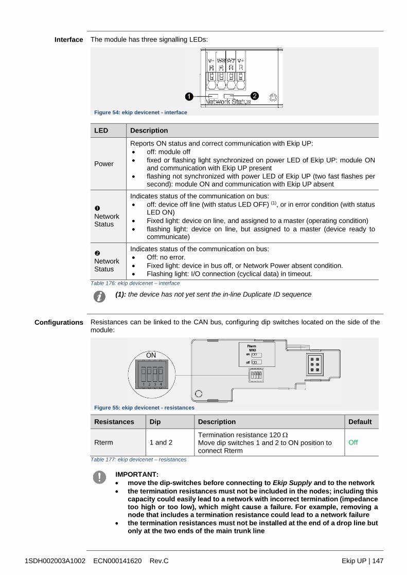
1SDH002003A1002 ECN000141620 Rev.C Ekip UP | 147
Interface The module has three signalling LEDs:
Figure 54: ekip devicenet - interface
LED Description
Power
Reports ON status and correct communication with Ekip UP: off: module off fixed or flashing light synchronized on power LED of Ekip UP: module ON
and communication with Ekip UP present flashing not synchronized with power LED of Ekip UP (two fast flashes per
second): module ON and communication with Ekip UP absent
NetworkStatus
Indicates status of the communication on bus: off: device off line (with status LED OFF) (1), or in error condition (with status
LED ON) Fixed light: device on line, and assigned to a master (operating condition) flashing light: device on line, but assigned to a master (device ready to
communicate)
NetworkStatus
Indicates status of the communication on bus: Off: no error. Fixed light: device in bus off, or Network Power absent condition. Flashing light: I/O connection (cyclical data) in timeout.
Table 176: ekip devicenet – interface
(1): the device has not yet sent the in-line Duplicate ID sequence
Configurations Resistances can be linked to the CAN bus, configuring dip switches located on the side of themodule:
Figure 55: ekip devicenet - resistances
Resistances Dip Description Default
Rterm 1 and 2Termination resistance 120 Move dip switches 1 and 2 to ON position toconnect Rterm
Off
Table 177: ekip devicenet – resistances
IMPORTANT: move the dip-switches before connecting to Ekip Supply and to the network the termination resistances must not be included in the nodes; including this
capacity could easily lead to a network with incorrect termination (impedancetoo high or too low), which might cause a failure. For example, removing anode that includes a termination resistance could lead to a network failure
the termination resistances must not be installed at the end of a drop line butonly at the two ends of the main trunk line
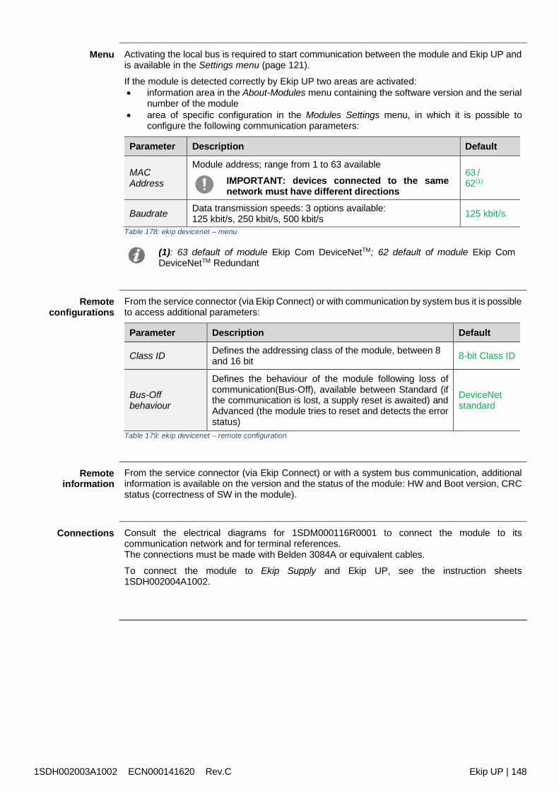
1SDH002003A1002 ECN000141620 Rev.C Ekip UP | 148
Menu Activating the local bus is required to start communication between the module and Ekip UP andis available in the Settings menu (page 121).
If the module is detected correctly by Ekip UP two areas are activated: information area in the About-Modules menu containing the software version and the serial
number of the module area of specific configuration in the Modules Settings menu, in which it is possible to
configure the following communication parameters:
Parameter Description Default
MACAddress
Module address; range from 1 to 63 available
IMPORTANT: devices connected to the samenetwork must have different directions
63 /62(1)
Baudrate Data transmission speeds: 3 options available:125 kbit/s, 250 kbit/s, 500 kbit/s 125 kbit/s
Table 178: ekip devicenet – menu
(1): 63 default of module Ekip Com DeviceNetTM; 62 default of module Ekip ComDeviceNetTM Redundant
Remoteconfigurations
From the service connector (via Ekip Connect) or with communication by system bus it is possibleto access additional parameters:
Parameter Description Default
Class ID Defines the addressing class of the module, between 8and 16 bit 8-bit Class ID
Bus-Offbehaviour
Defines the behaviour of the module following loss ofcommunication(Bus-Off), available between Standard (ifthe communication is lost, a supply reset is awaited) andAdvanced (the module tries to reset and detects the errorstatus)
DeviceNetstandard
Table 179: ekip devicenet – remote configuration
Remoteinformation
From the service connector (via Ekip Connect) or with a system bus communication, additionalinformation is available on the version and the status of the module: HW and Boot version, CRCstatus (correctness of SW in the module).
Connections Consult the electrical diagrams for 1SDM000116R0001 to connect the module to itscommunication network and for terminal references.The connections must be made with Belden 3084A or equivalent cables.
To connect the module to Ekip Supply and Ekip UP, see the instruction sheets1SDH002004A1002.
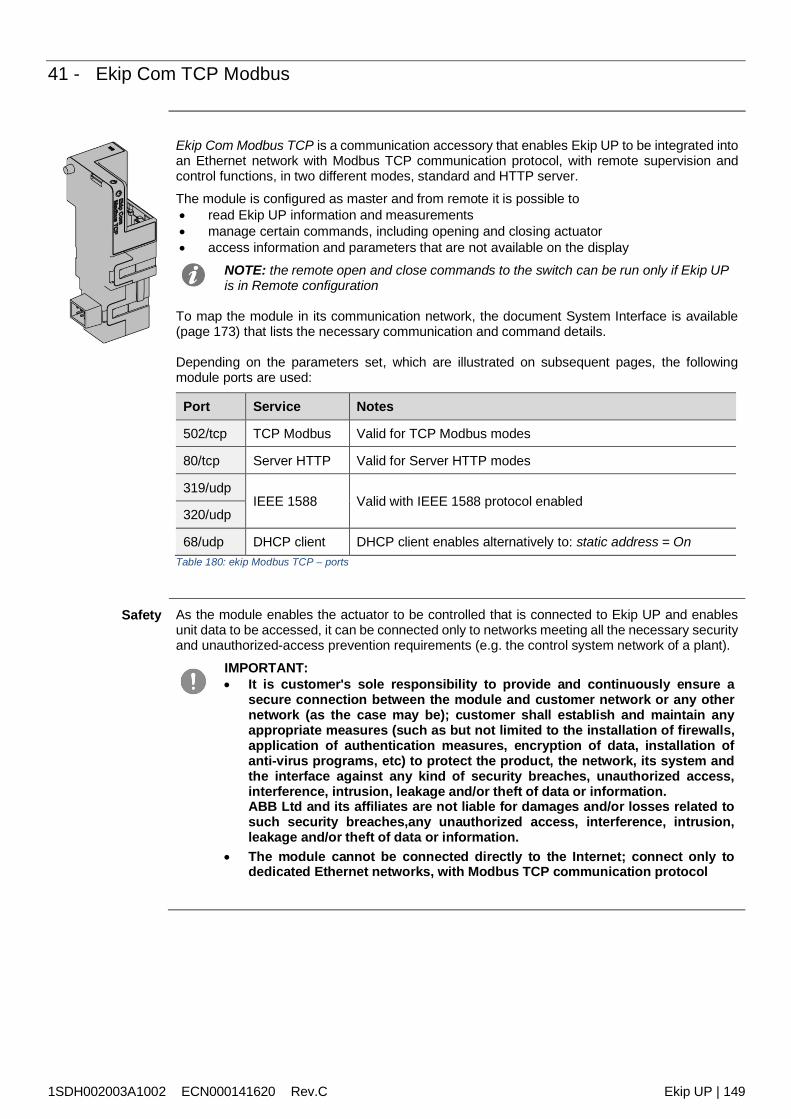
1SDH002003A1002 ECN000141620 Rev.C Ekip UP | 149
41 - Ekip Com TCP Modbus
Ekip Com Modbus TCP is a communication accessory that enables Ekip UP to be integrated intoan Ethernet network with Modbus TCP communication protocol, with remote supervision andcontrol functions, in two different modes, standard and HTTP server.The module is configured as master and from remote it is possible to read Ekip UP information and measurements manage certain commands, including opening and closing actuator access information and parameters that are not available on the display
NOTE: the remote open and close commands to the switch can be run only if Ekip UPis in Remote configuration
To map the module in its communication network, the document System Interface is available(page 173) that lists the necessary communication and command details.
Depending on the parameters set, which are illustrated on subsequent pages, the followingmodule ports are used:
Port Service Notes
502/tcp TCP Modbus Valid for TCP Modbus modes
80/tcp Server HTTP Valid for Server HTTP modes
319/udpIEEE 1588 Valid with IEEE 1588 protocol enabled
320/udp
68/udp DHCP client DHCP client enables alternatively to: static address = OnTable 180: ekip Modbus TCP – ports
Safety As the module enables the actuator to be controlled that is connected to Ekip UP and enablesunit data to be accessed, it can be connected only to networks meeting all the necessary securityand unauthorized-access prevention requirements (e.g. the control system network of a plant).
IMPORTANT: It is customer's sole responsibility to provide and continuously ensure a
secure connection between the module and customer network or any othernetwork (as the case may be); customer shall establish and maintain anyappropriate measures (such as but not limited to the installation of firewalls,application of authentication measures, encryption of data, installation ofanti-virus programs, etc) to protect the product, the network, its system andthe interface against any kind of security breaches, unauthorized access,interference, intrusion, leakage and/or theft of data or information.ABB Ltd and its affiliates are not liable for damages and/or losses related tosuch security breaches,any unauthorized access, interference, intrusion,leakage and/or theft of data or information.
The module cannot be connected directly to the Internet; connect only todedicated Ethernet networks, with Modbus TCP communication protocol
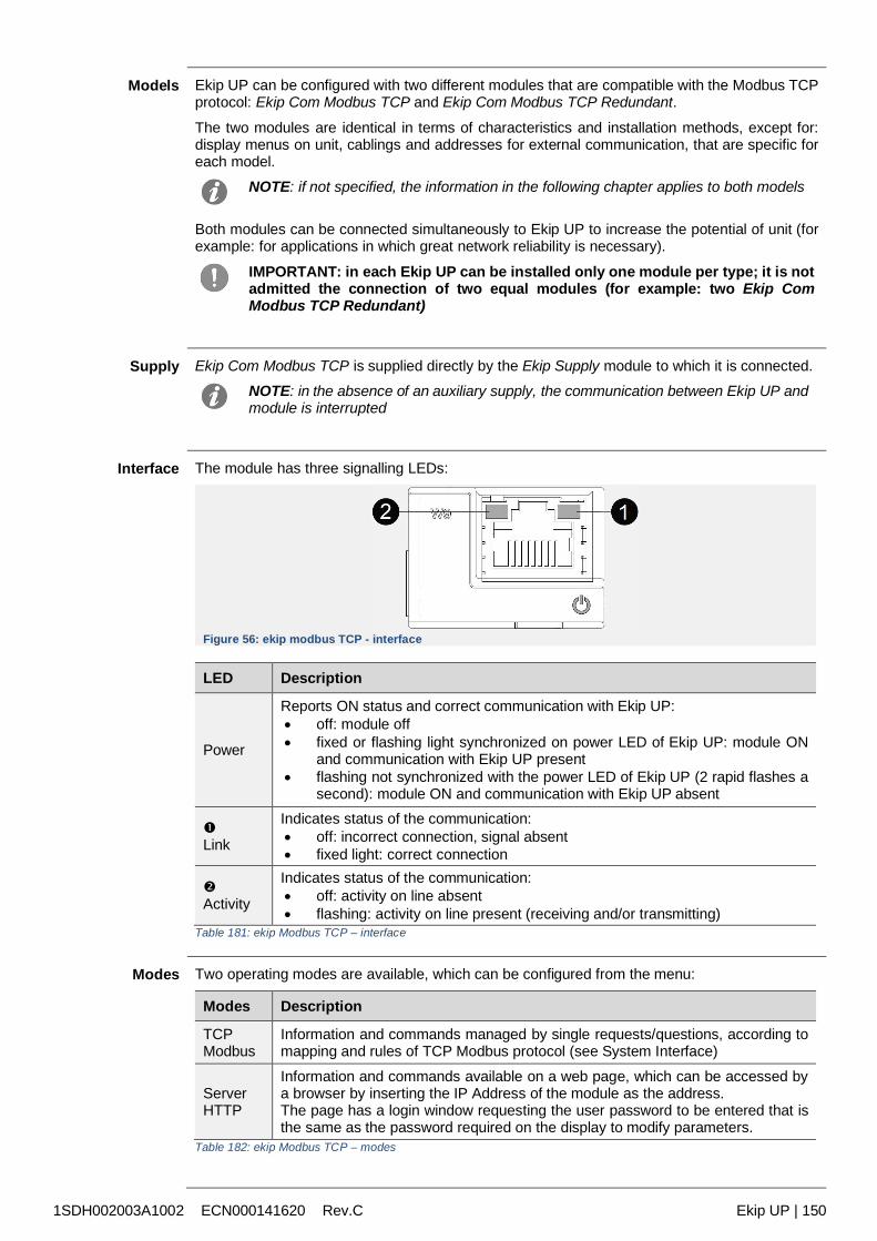
1SDH002003A1002 ECN000141620 Rev.C Ekip UP | 150
Models Ekip UP can be configured with two different modules that are compatible with the Modbus TCPprotocol: Ekip Com Modbus TCP and Ekip Com Modbus TCP Redundant.
The two modules are identical in terms of characteristics and installation methods, except for:display menus on unit, cablings and addresses for external communication, that are specific foreach model.
NOTE: if not specified, the information in the following chapter applies to both models
Both modules can be connected simultaneously to Ekip UP to increase the potential of unit (forexample: for applications in which great network reliability is necessary).
IMPORTANT: in each Ekip UP can be installed only one module per type; it is notadmitted the connection of two equal modules (for example: two Ekip ComModbus TCP Redundant)
Supply Ekip Com Modbus TCP is supplied directly by the Ekip Supply module to which it is connected.NOTE: in the absence of an auxiliary supply, the communication between Ekip UP andmodule is interrupted
Interface The module has three signalling LEDs:
Figure 56: ekip modbus TCP - interface
LED Description
Power
Reports ON status and correct communication with Ekip UP: off: module off fixed or flashing light synchronized on power LED of Ekip UP: module ON
and communication with Ekip UP present flashing not synchronized with the power LED of Ekip UP (2 rapid flashes a
second): module ON and communication with Ekip UP absent
Link
Indicates status of the communication: off: incorrect connection, signal absent fixed light: correct connection
Activity
Indicates status of the communication: off: activity on line absent flashing: activity on line present (receiving and/or transmitting)
Table 181: ekip Modbus TCP – interface
Modes Two operating modes are available, which can be configured from the menu:
Modes Description
TCPModbus
Information and commands managed by single requests/questions, according tomapping and rules of TCP Modbus protocol (see System Interface)
ServerHTTP
Information and commands available on a web page, which can be accessed bya browser by inserting the IP Address of the module as the address.The page has a login window requesting the user password to be entered that isthe same as the password required on the display to modify parameters.
Table 182: ekip Modbus TCP – modes
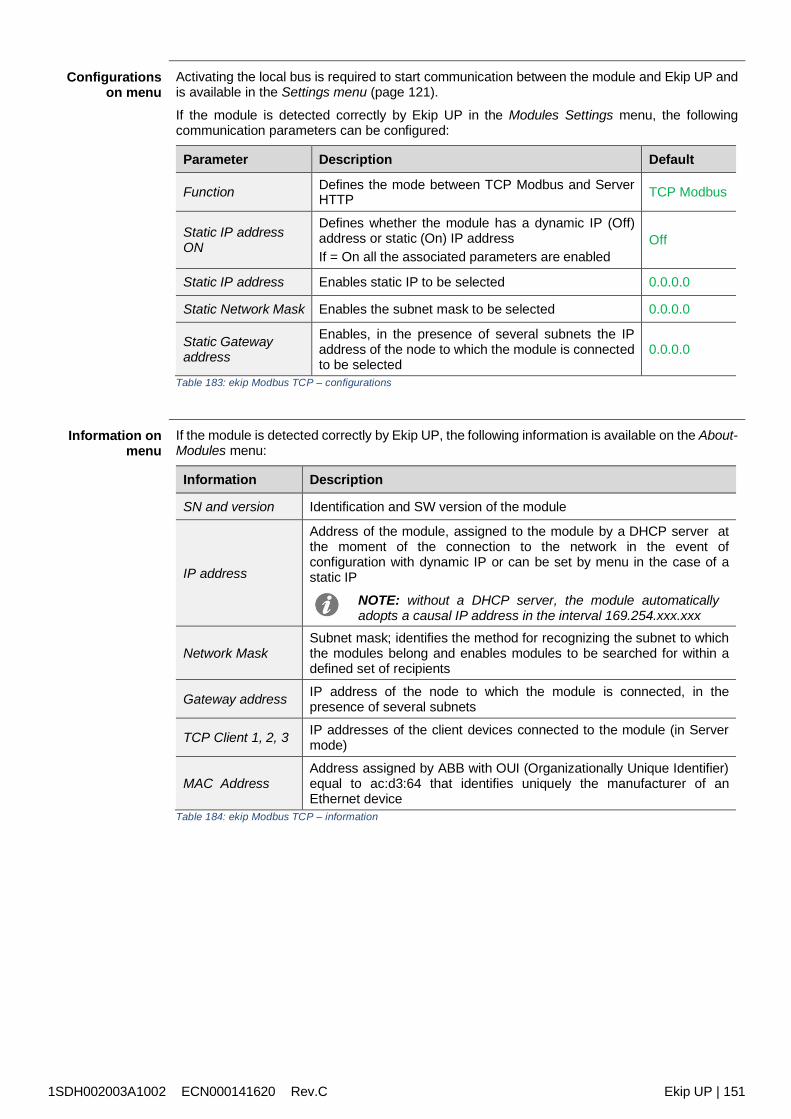
1SDH002003A1002 ECN000141620 Rev.C Ekip UP | 151
Configurationson menu
Activating the local bus is required to start communication between the module and Ekip UP andis available in the Settings menu (page 121).
If the module is detected correctly by Ekip UP in the Modules Settings menu, the followingcommunication parameters can be configured:
Parameter Description Default
Function Defines the mode between TCP Modbus and ServerHTTP TCP Modbus
Static IP addressON
Defines whether the module has a dynamic IP (Off)address or static (On) IP addressIf = On all the associated parameters are enabled
Off
Static IP address Enables static IP to be selected 0.0.0.0
Static Network Mask Enables the subnet mask to be selected 0.0.0.0
Static Gatewayaddress
Enables, in the presence of several subnets the IPaddress of the node to which the module is connectedto be selected
0.0.0.0
Table 183: ekip Modbus TCP – configurations
Information onmenu
If the module is detected correctly by Ekip UP, the following information is available on the About-Modules menu:
Information Description
SN and version Identification and SW version of the module
IP address
Address of the module, assigned to the module by a DHCP server atthe moment of the connection to the network in the event ofconfiguration with dynamic IP or can be set by menu in the case of astatic IP
NOTE: without a DHCP server, the module automaticallyadopts a causal IP address in the interval 169.254.xxx.xxx
Network MaskSubnet mask; identifies the method for recognizing the subnet to whichthe modules belong and enables modules to be searched for within adefined set of recipients
Gateway address IP address of the node to which the module is connected, in thepresence of several subnets
TCP Client 1, 2, 3 IP addresses of the client devices connected to the module (in Servermode)
MAC AddressAddress assigned by ABB with OUI (Organizationally Unique Identifier)equal to ac:d3:64 that identifies uniquely the manufacturer of anEthernet device
Table 184: ekip Modbus TCP – information
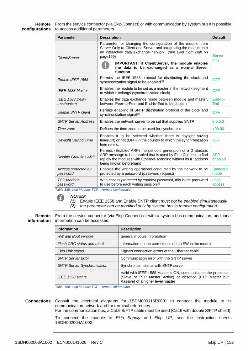
1SDH002003A1002 ECN000141620 Rev.C Ekip UP | 152
Remoteconfigurations
From the service connector (via Ekip Connect) or with communication by system bus it is possibleto access additional parameters
Parameter Description Default
Client/Server
Parameter for changing the configuration of the module fromServer Only to Client and Server and integrating the module intoan interactive data exchange network (see Ekip Com Hub onpage169)
IMPORTANT: if Client/Server, the module enablesthe data to be exchanged as a normal Serverfunction
Serveronly
Enable IEEE 1558 Permits the IEEE 1588 protocol for distributing the clock andsynchronization signal to be enabled(1) OFF
IEEE 1588 Master Enables the module to be set as a master in the network segmentto which it belongs (synchronization clock) OFF
IEEE 1588 Delaymechanism
Enables the data exchange mode between module and master,between Peer-to-Peer and End-to-End to be chosen
End-to-End
Enable SNTP client Permits enabling of SNTP distribution protocol of the clock andsynchronization signal(1) OFF
SNTP Server Address Enables the network server to be set that supplies SNTP 0.0.0.0
Time zone Defines the time zone to be used for synchronism +00:00
Daylight Saving TimeEnables it to be selected whether there is daylight savingtime(ON) or not (OFF) in the country to which the synchronizationtime refers.
OFF
Disable Gratuitos ARP
Permits (Enabled ARP) the periodic generation of a GratuituosARP message to be enabled that is used by Ekip Connect to findrapidly the modules with Ethernet scanning without its IP addressbeing known beforehand
ARPenabled
Access protected bypassword
Enables the writing operations conducted by the network to beprotected by a password (password request)
Standardmode
TCP Modbuspassword
With access protected by enabled password, this is the passwordto use before each writing session(2)
Localaccess
Table 185: ekip Modbus TCP – remote configuration
NOTES:(1) Enable IEEE 1558 and Enable SNTP client must not be enabled simultaneously(2) the parameter can be modified only by system bus in remote configuration
Remoteinformation
From the service connector (via Ekip Connect) or with a system bus communication, additionalinformation can be accessed:
Information Description
HW and Boot version general module information
Flash CRC status and result information on the correctness of the SW in the module
Ekip Link status Signals connection errors of the Ethernet cable
SNTP Server Error Communication error with the SNTP server
SNTP Server Synchronisation Synchronism status with SNTP server
IEEE 1558 statusValid with IEEE 1588 Master = ON, communicates the presence(Slave or PTP Master Active) or absence (PTP Master butPassive) of a higher level master
Table 186: ekip Modbus TCP – remote information
Connections Consult the electrical diagrams for 1SDM000116R0001 to connect the module to itscommunication network and for terminal references.For the communication bus, a Cat.6 S/FTP cable must be used (Cat.6 with double S/FTP shield).
To connect the module to Ekip Supply and Ekip UP, see the instruction sheets1SDH002004A1002.
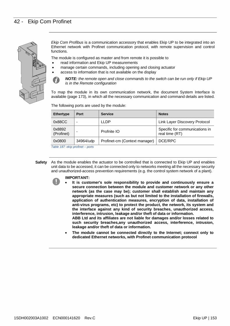
1SDH002003A1002 ECN000141620 Rev.C Ekip UP | 153
42 - Ekip Com Profinet
Ekip Com Profibus is a communication accessory that enables Ekip UP to be integrated into anEthernet network with Profinet communication protocol, with remote supervision and controlfunctions.The module is configured as master and from remote it is possible to read information and Ekip UP measurements manage certain commands, including opening and closing actuator access to information that is not available on the display
NOTE: the remote open and close commands to the switch can be run only if Ekip UPis in the Remote configuration
To map the module in its own communication network, the document System Interface isavailable (page 173), in which all the necessary communication and command details are listed.
The following ports are used by the module:
Ethertype Port Service Notes
0x88CC - LLDP Link Layer Discovery Protocol
0x8892(Profinet) - Profnite IO Specific for communications in
real time (RT)
0x0800 34964/udp Profinet-cm (Context manager) DCE/RPCTable 187: ekip profinet – ports
Safety As the module enables the actuator to be controlled that is connected to Ekip UP and enablesunit data to be accessed, it can be connected only to networks meeting all the necessary securityand unauthorized-access prevention requirements (e.g. the control system network of a plant).
IMPORTANT: It is customer's sole responsibility to provide and continuously ensure a
secure connection between the module and customer network or any othernetwork (as the case may be); customer shall establish and maintain anyappropriate measures (such as but not limited to the installation of firewalls,application of authentication measures, encryption of data, installation ofanti-virus programs, etc) to protect the product, the network, its system andthe interface against any kind of security breaches, unauthorized access,interference, intrusion, leakage and/or theft of data or information.ABB Ltd and its affiliates are not liable for damages and/or losses related tosuch security breaches,any unauthorized access, interference, intrusion,leakage and/or theft of data or information.
The module cannot be connected directly to the Internet; connect only todedicated Ethernet networks, with Profinet communication protocol
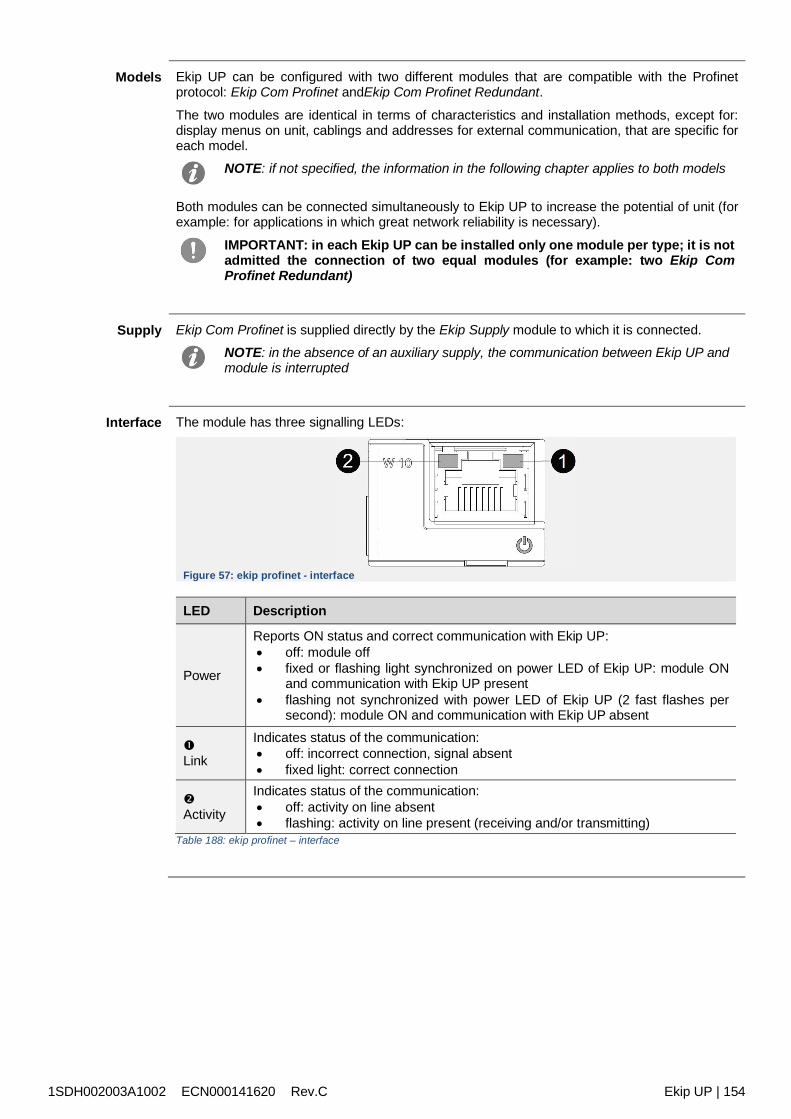
1SDH002003A1002 ECN000141620 Rev.C Ekip UP | 154
Models Ekip UP can be configured with two different modules that are compatible with the Profinetprotocol: Ekip Com Profinet andEkip Com Profinet Redundant.
The two modules are identical in terms of characteristics and installation methods, except for:display menus on unit, cablings and addresses for external communication, that are specific foreach model.
NOTE: if not specified, the information in the following chapter applies to both models
Both modules can be connected simultaneously to Ekip UP to increase the potential of unit (forexample: for applications in which great network reliability is necessary).
IMPORTANT: in each Ekip UP can be installed only one module per type; it is notadmitted the connection of two equal modules (for example: two Ekip ComProfinet Redundant)
Supply Ekip Com Profinet is supplied directly by the Ekip Supply module to which it is connected.NOTE: in the absence of an auxiliary supply, the communication between Ekip UP andmodule is interrupted
Interface The module has three signalling LEDs:
Figure 57: ekip profinet - interface
LED Description
Power
Reports ON status and correct communication with Ekip UP: off: module off fixed or flashing light synchronized on power LED of Ekip UP: module ON
and communication with Ekip UP present flashing not synchronized with power LED of Ekip UP (2 fast flashes per
second): module ON and communication with Ekip UP absent
Link
Indicates status of the communication: off: incorrect connection, signal absent fixed light: correct connection
Activity
Indicates status of the communication: off: activity on line absent flashing: activity on line present (receiving and/or transmitting)
Table 188: ekip profinet – interface
1SDH002003A1002 ECN000141620 Rev.C Ekip UP | 155
Menu Activating the local bus is required to start communication between the module and Ekip UP andis available in the Settings menu (page 121).
If the module is detected correctly by Ekip UP, the following information is available in the About-Modules menu:
Information Description
SN and version Identification and SW version of the module
MAC AddressAddress assigned by ABB with OUI (Organizationally Unique Identifier)equal to ac:d3:64 that identifies uniquely the manufacturer of anEthernet device
Table 189: ekip profinet – menu
Remoteinformation
From the service connector (via Ekip Connect) or with a system bus communication, additionalinformation is available on the version and the status of the module: HW and Boot version, CRCstatus (correctness of SW in the module).
Connections Consult the electrical diagrams for 1SDM000116R0001 to connect the module to itscommunication network and for terminal references.For the communication bus, a Cat.6 S/FTP cable must be used (Cat.6 with double S/FTP shield).
To connect the module to Ekip Supply and Ekip UP, see the instruction sheets1SDH002004A1002.
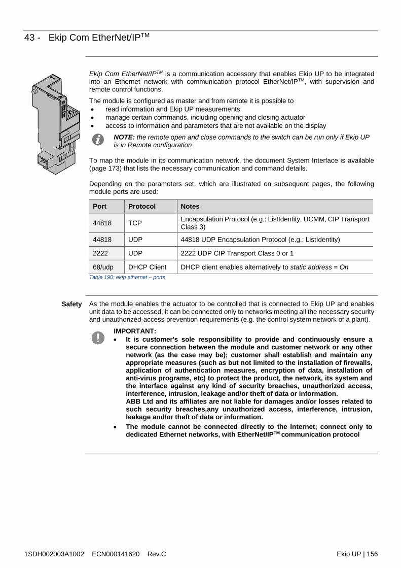
1SDH002003A1002 ECN000141620 Rev.C Ekip UP | 156
43 - Ekip Com EtherNet/IPTM
Ekip Com EtherNet/IPTM is a communication accessory that enables Ekip UP to be integratedinto an Ethernet network with communication protocol EtherNet/IPTM, with supervision andremote control functions.The module is configured as master and from remote it is possible to read information and Ekip UP measurements manage certain commands, including opening and closing actuator access to information and parameters that are not available on the display
NOTE: the remote open and close commands to the switch can be run only if Ekip UPis in Remote configuration
To map the module in its communication network, the document System Interface is available(page 173) that lists the necessary communication and command details.
Depending on the parameters set, which are illustrated on subsequent pages, the followingmodule ports are used:
Port Protocol Notes
44818 TCP Encapsulation Protocol (e.g.: ListIdentity, UCMM, CIP TransportClass 3)
44818 UDP 44818 UDP Encapsulation Protocol (e.g.: ListIdentity)
2222 UDP 2222 UDP CIP Transport Class 0 or 1
68/udp DHCP Client DHCP client enables alternatively to static address = OnTable 190: ekip ethernet – ports
Safety As the module enables the actuator to be controlled that is connected to Ekip UP and enablesunit data to be accessed, it can be connected only to networks meeting all the necessary securityand unauthorized-access prevention requirements (e.g. the control system network of a plant).
IMPORTANT: It is customer's sole responsibility to provide and continuously ensure a
secure connection between the module and customer network or any othernetwork (as the case may be); customer shall establish and maintain anyappropriate measures (such as but not limited to the installation of firewalls,application of authentication measures, encryption of data, installation ofanti-virus programs, etc) to protect the product, the network, its system andthe interface against any kind of security breaches, unauthorized access,interference, intrusion, leakage and/or theft of data or information.ABB Ltd and its affiliates are not liable for damages and/or losses related tosuch security breaches,any unauthorized access, interference, intrusion,leakage and/or theft of data or information.
The module cannot be connected directly to the Internet; connect only todedicated Ethernet networks, with EtherNet/IPTM communication protocol
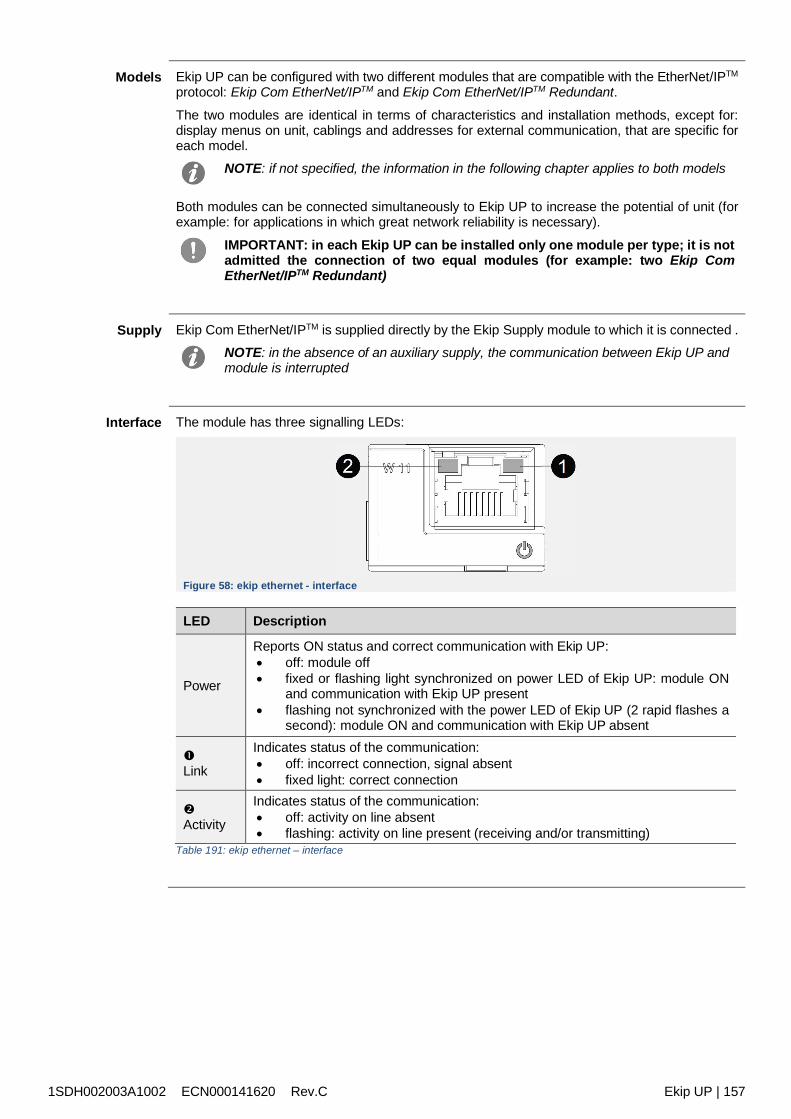
1SDH002003A1002 ECN000141620 Rev.C Ekip UP | 157
Models Ekip UP can be configured with two different modules that are compatible with the EtherNet/IPTM
protocol: Ekip Com EtherNet/IPTM and Ekip Com EtherNet/IPTM Redundant.
The two modules are identical in terms of characteristics and installation methods, except for:display menus on unit, cablings and addresses for external communication, that are specific foreach model.
NOTE: if not specified, the information in the following chapter applies to both models
Both modules can be connected simultaneously to Ekip UP to increase the potential of unit (forexample: for applications in which great network reliability is necessary).
IMPORTANT: in each Ekip UP can be installed only one module per type; it is notadmitted the connection of two equal modules (for example: two Ekip ComEtherNet/IPTM Redundant)
Supply Ekip Com EtherNet/IPTM is supplied directly by the Ekip Supply module to which it is connected .NOTE: in the absence of an auxiliary supply, the communication between Ekip UP andmodule is interrupted
Interface The module has three signalling LEDs:
Figure 58: ekip ethernet - interface
LED Description
Power
Reports ON status and correct communication with Ekip UP: off: module off fixed or flashing light synchronized on power LED of Ekip UP: module ON
and communication with Ekip UP present flashing not synchronized with the power LED of Ekip UP (2 rapid flashes a
second): module ON and communication with Ekip UP absent
Link
Indicates status of the communication: off: incorrect connection, signal absent fixed light: correct connection
Activity
Indicates status of the communication: off: activity on line absent flashing: activity on line present (receiving and/or transmitting)
Table 191: ekip ethernet – interface
1SDH002003A1002 ECN000141620 Rev.C Ekip UP | 158
Configurationson menu
Activating the local bus is required to start communication between the module and Ekip UP andis available in the Settings menu (page 121).
If the module is detected correctly by Ekip UP the following communication parameters can beconfigured in the Settings Modules menu:
Parameter Description Default
Static IP addressON
Defines whether the module has the dynamic IPaddress (Off) or static IP address (On)If = On all associated parameters are enabled
Off
Static IP address Enables the static IP to be selected 0.0.0.0
Static NetworkMask Enables the subnet mask to be selected 0.0.0.0
Static Gatewayaddress
In the presence of several subnets it enables the IPaddress to be selected of the node to which the moduleis connected
0.0.0.0
Table 192: ekip ethernet – configurations
Information onmenu
If the module is detected correctly by Ekip UP in the About-Modules menu the followinginformation is available:
Information Description
SN and version Identification and SW version of the module
IP address
Address of the module, assigned to the module by a DHCP server atthe moment of the connection to the network in the event ofconfiguration with dynamic IP or can be set by menu in the case of astatic IP
NOTE: without a DHCP server, the module automaticallyadopts a causal IP address in the interval 169.254.xxx.xxx
Network MaskSubnet mask; identifies the method for recognizing the subnet to whichthe modules belong and enables modules to be searched for within adefined set of recipients
Gateway address IP address of the node to which the module is connected, in thepresence of several subnets
MAC AddressAddress assigned by ABB with OUI (Organizationally Unique Identifier)equal to ac:d3:64 that identifies uniquely the manufacturer of anEthernet device
Table 193: ekip ethernet – information
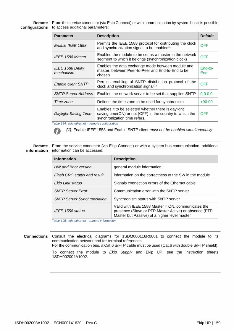
1SDH002003A1002 ECN000141620 Rev.C Ekip UP | 159
Remoteconfigurations
From the service connector (via Ekip Connect) or with communication by system bus it is possibleto access additional parameters:
Parameter Description Default
Enable IEEE 1558 Permits the IEEE 1588 protocol for distributing the clockand synchronization signal to be enabled(1) OFF
IEEE 1588 Master Enables the module to be set as a master in the networksegment to which it belongs (synchronization clock) OFF
IEEE 1588 Delaymechanism
Enables the data exchange mode between module andmaster, between Peer-to-Peer and End-to-End to bechosen
End-to-End
Enable client SNTP Permits enabling of SNTP distribution protocol of theclock and synchronization signal(1) OFF
SNTP Server Address Enables the network server to be set that supplies SNTP 0.0.0.0
Time zone Defines the time zone to be used for synchronism +00:00
Daylight Saving TimeEnables it to be selected whether there is daylightsaving time(ON) or not (OFF) in the country to which thesynchronization time refers.
OFF
Table 194: ekip ethernet – remote configuration
(1): Enable IEEE 1558 and Enable SNTP client must not be enabled simultaneously
Remoteinformation
From the service connector (via Ekip Connect) or with a system bus communication, additionalinformation can be accessed:
Information Description
HW and Boot version general module information
Flash CRC status and result information on the correctness of the SW in the module
Ekip Link status Signals connection errors of the Ethernet cable
SNTP Server Error Communication error with the SNTP server
SNTP Server Synchronisation Synchronism status with SNTP server
IEEE 1558 statusValid with IEEE 1588 Master = ON, communicates thepresence (Slave or PTP Master Active) or absence (PTPMaster but Passive) of a higher level master
Table 195: ekip ethernet – remote information
Connections Consult the electrical diagrams for 1SDM000116R0001 to connect the module to itscommunication network and for terminal references.For the communication bus, a Cat.6 S/FTP cable must be used (Cat.6 with double S/FTP shield).
To connect the module to Ekip Supply and Ekip UP, see the instruction sheets1SDH002004A1002.
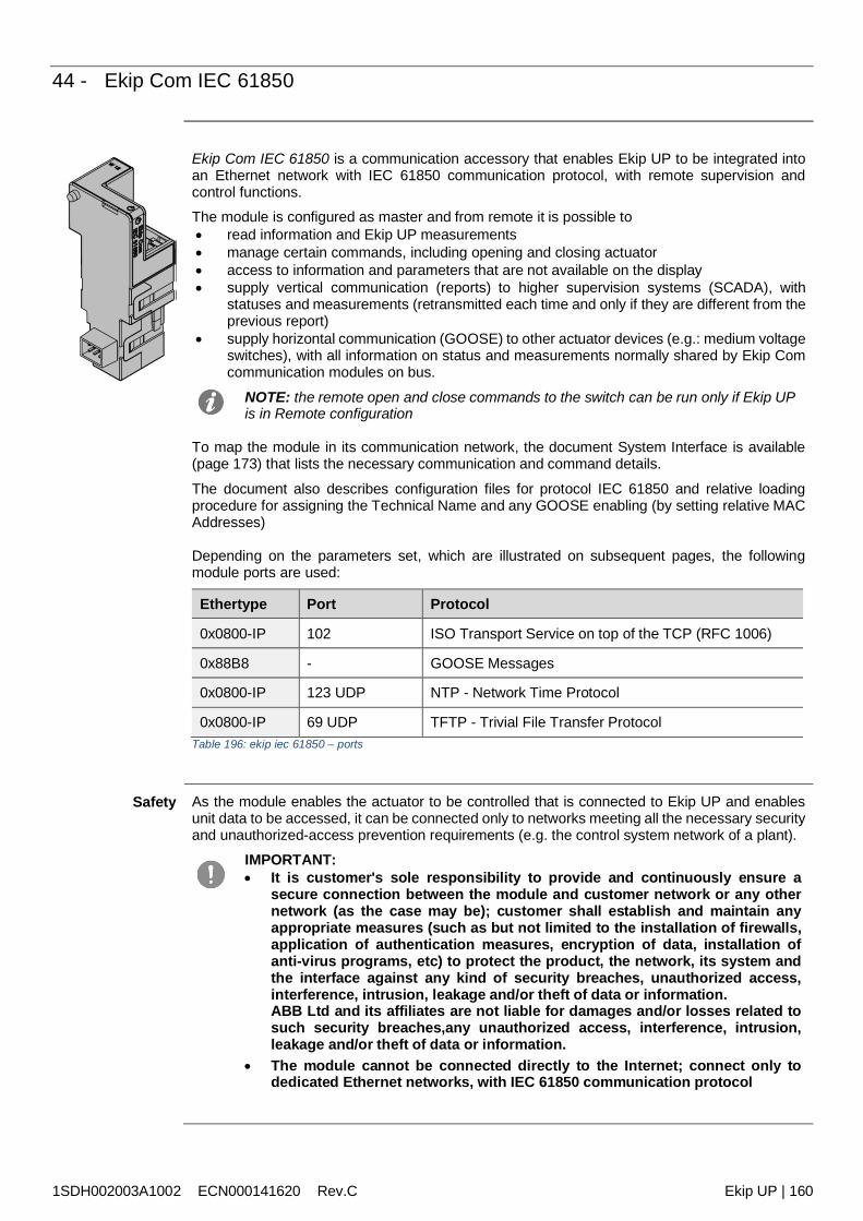
1SDH002003A1002 ECN000141620 Rev.C Ekip UP | 160
44 - Ekip Com IEC 61850
Ekip Com IEC 61850 is a communication accessory that enables Ekip UP to be integrated intoan Ethernet network with IEC 61850 communication protocol, with remote supervision andcontrol functions.The module is configured as master and from remote it is possible to read information and Ekip UP measurements manage certain commands, including opening and closing actuator access to information and parameters that are not available on the display supply vertical communication (reports) to higher supervision systems (SCADA), with
statuses and measurements (retransmitted each time and only if they are different from theprevious report)
supply horizontal communication (GOOSE) to other actuator devices (e.g.: medium voltageswitches), with all information on status and measurements normally shared by Ekip Comcommunication modules on bus.
NOTE: the remote open and close commands to the switch can be run only if Ekip UPis in Remote configuration
To map the module in its communication network, the document System Interface is available(page 173) that lists the necessary communication and command details.
The document also describes configuration files for protocol IEC 61850 and relative loadingprocedure for assigning the Technical Name and any GOOSE enabling (by setting relative MACAddresses)
Depending on the parameters set, which are illustrated on subsequent pages, the followingmodule ports are used:
Ethertype Port Protocol
0x0800-IP 102 ISO Transport Service on top of the TCP (RFC 1006)
0x88B8 - GOOSE Messages
0x0800-IP 123 UDP NTP - Network Time Protocol
0x0800-IP 69 UDP TFTP - Trivial File Transfer ProtocolTable 196: ekip iec 61850 – ports
Safety As the module enables the actuator to be controlled that is connected to Ekip UP and enablesunit data to be accessed, it can be connected only to networks meeting all the necessary securityand unauthorized-access prevention requirements (e.g. the control system network of a plant).
IMPORTANT: It is customer's sole responsibility to provide and continuously ensure a
secure connection between the module and customer network or any othernetwork (as the case may be); customer shall establish and maintain anyappropriate measures (such as but not limited to the installation of firewalls,application of authentication measures, encryption of data, installation ofanti-virus programs, etc) to protect the product, the network, its system andthe interface against any kind of security breaches, unauthorized access,interference, intrusion, leakage and/or theft of data or information.ABB Ltd and its affiliates are not liable for damages and/or losses related tosuch security breaches,any unauthorized access, interference, intrusion,leakage and/or theft of data or information.
The module cannot be connected directly to the Internet; connect only todedicated Ethernet networks, with IEC 61850 communication protocol
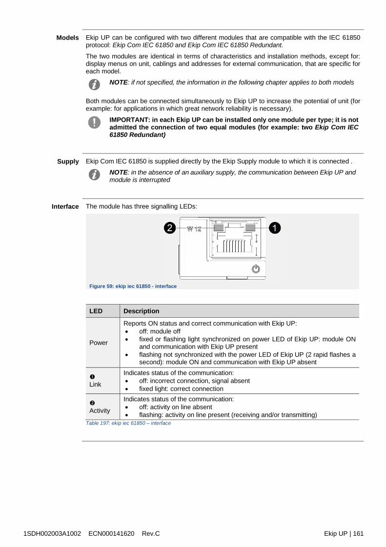
1SDH002003A1002 ECN000141620 Rev.C Ekip UP | 161
Models Ekip UP can be configured with two different modules that are compatible with the IEC 61850protocol: Ekip Com IEC 61850 and Ekip Com IEC 61850 Redundant.
The two modules are identical in terms of characteristics and installation methods, except for:display menus on unit, cablings and addresses for external communication, that are specific foreach model.
NOTE: if not specified, the information in the following chapter applies to both models
Both modules can be connected simultaneously to Ekip UP to increase the potential of unit (forexample: for applications in which great network reliability is necessary).
IMPORTANT: in each Ekip UP can be installed only one module per type; it is notadmitted the connection of two equal modules (for example: two Ekip Com IEC61850 Redundant)
Supply Ekip Com IEC 61850 is supplied directly by the Ekip Supply module to which it is connected .NOTE: in the absence of an auxiliary supply, the communication between Ekip UP andmodule is interrupted
Interface The module has three signalling LEDs:
Figure 59: ekip iec 61850 - interface
LED Description
Power
Reports ON status and correct communication with Ekip UP: off: module off fixed or flashing light synchronized on power LED of Ekip UP: module ON
and communication with Ekip UP present flashing not synchronized with the power LED of Ekip UP (2 rapid flashes a
second): module ON and communication with Ekip UP absent
Link
Indicates status of the communication: off: incorrect connection, signal absent fixed light: correct connection
Activity
Indicates status of the communication: off: activity on line absent flashing: activity on line present (receiving and/or transmitting)
Table 197: ekip iec 61850 – interface
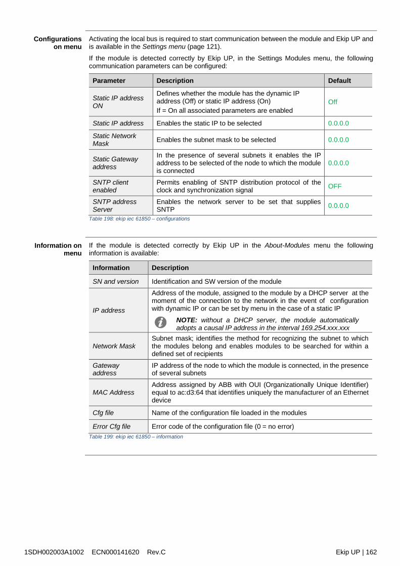
1SDH002003A1002 ECN000141620 Rev.C Ekip UP | 162
Configurationson menu
Activating the local bus is required to start communication between the module and Ekip UP andis available in the Settings menu (page 121).
If the module is detected correctly by Ekip UP, in the Settings Modules menu, the followingcommunication parameters can be configured:
Parameter Description Default
Static IP addressON
Defines whether the module has the dynamic IPaddress (Off) or static IP address (On)If = On all associated parameters are enabled
Off
Static IP address Enables the static IP to be selected 0.0.0.0
Static NetworkMask Enables the subnet mask to be selected 0.0.0.0
Static Gatewayaddress
In the presence of several subnets it enables the IPaddress to be selected of the node to which the moduleis connected
0.0.0.0
SNTP clientenabled
Permits enabling of SNTP distribution protocol of theclock and synchronization signal OFF
SNTP addressServer
Enables the network server to be set that suppliesSNTP 0.0.0.0
Table 198: ekip iec 61850 – configurations
Information onmenu
If the module is detected correctly by Ekip UP in the About-Modules menu the followinginformation is available:
Information Description
SN and version Identification and SW version of the module
IP address
Address of the module, assigned to the module by a DHCP server at themoment of the connection to the network in the event of configurationwith dynamic IP or can be set by menu in the case of a static IP
NOTE: without a DHCP server, the module automaticallyadopts a causal IP address in the interval 169.254.xxx.xxx
Network MaskSubnet mask; identifies the method for recognizing the subnet to whichthe modules belong and enables modules to be searched for within adefined set of recipients
Gatewayaddress
IP address of the node to which the module is connected, in the presenceof several subnets
MAC AddressAddress assigned by ABB with OUI (Organizationally Unique Identifier)equal to ac:d3:64 that identifies uniquely the manufacturer of an Ethernetdevice
Cfg file Name of the configuration file loaded in the modules
Error Cfg file Error code of the configuration file (0 = no error)Table 199: ekip iec 61850 – information
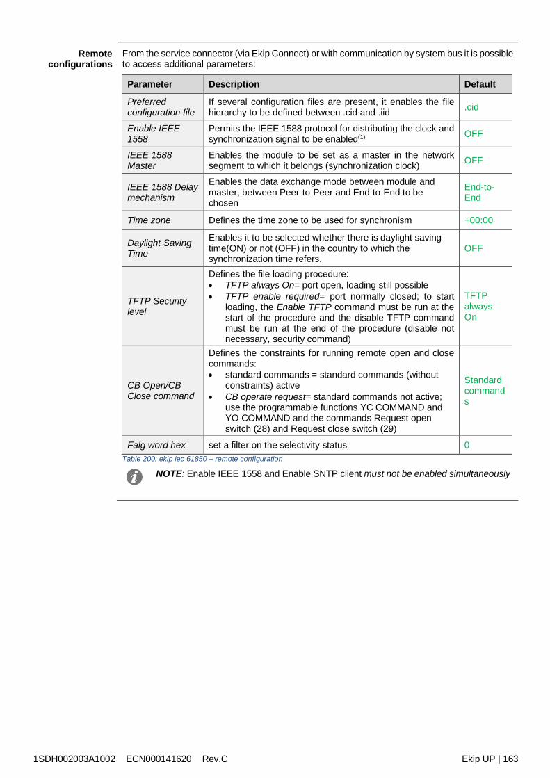
1SDH002003A1002 ECN000141620 Rev.C Ekip UP | 163
Remoteconfigurations
From the service connector (via Ekip Connect) or with communication by system bus it is possibleto access additional parameters:
Parameter Description Default
Preferredconfiguration file
If several configuration files are present, it enables the filehierarchy to be defined between .cid and .iid .cid
Enable IEEE1558
Permits the IEEE 1588 protocol for distributing the clock andsynchronization signal to be enabled(1) OFF
IEEE 1588Master
Enables the module to be set as a master in the networksegment to which it belongs (synchronization clock) OFF
IEEE 1588 Delaymechanism
Enables the data exchange mode between module andmaster, between Peer-to-Peer and End-to-End to bechosen
End-to-End
Time zone Defines the time zone to be used for synchronism +00:00
Daylight SavingTime
Enables it to be selected whether there is daylight savingtime(ON) or not (OFF) in the country to which thesynchronization time refers.
OFF
TFTP Securitylevel
Defines the file loading procedure: TFTP always On= port open, loading still possible TFTP enable required= port normally closed; to start
loading, the Enable TFTP command must be run at thestart of the procedure and the disable TFTP commandmust be run at the end of the procedure (disable notnecessary, security command)
TFTPalwaysOn
CB Open/CBClose command
Defines the constraints for running remote open and closecommands: standard commands = standard commands (without
constraints) active CB operate request= standard commands not active;
use the programmable functions YC COMMAND andYO COMMAND and the commands Request openswitch (28) and Request close switch (29)
Standardcommands
Falg word hex set a filter on the selectivity status 0Table 200: ekip iec 61850 – remote configuration
NOTE: Enable IEEE 1558 and Enable SNTP client must not be enabled simultaneously
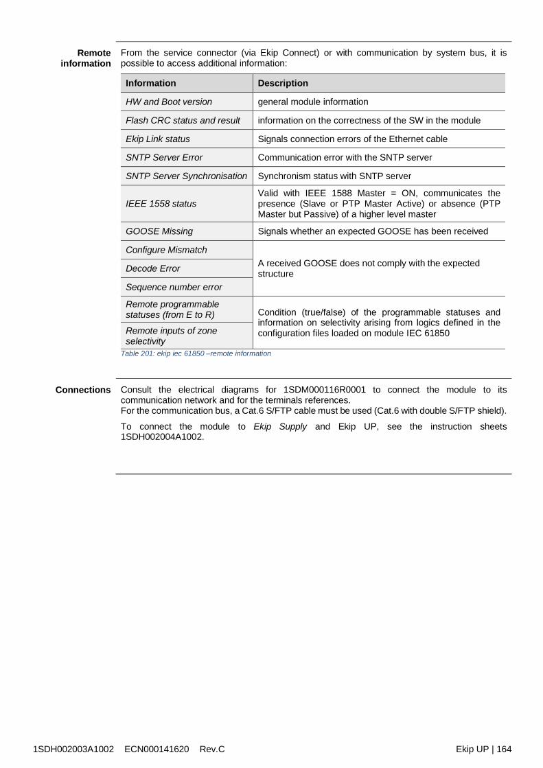
1SDH002003A1002 ECN000141620 Rev.C Ekip UP | 164
Remoteinformation
From the service connector (via Ekip Connect) or with communication by system bus, it ispossible to access additional information:
Information Description
HW and Boot version general module information
Flash CRC status and result information on the correctness of the SW in the module
Ekip Link status Signals connection errors of the Ethernet cable
SNTP Server Error Communication error with the SNTP server
SNTP Server Synchronisation Synchronism status with SNTP server
IEEE 1558 statusValid with IEEE 1588 Master = ON, communicates thepresence (Slave or PTP Master Active) or absence (PTPMaster but Passive) of a higher level master
GOOSE Missing Signals whether an expected GOOSE has been received
Configure MismatchA received GOOSE does not comply with the expectedstructureDecode Error
Sequence number error
Remote programmablestatuses (from E to R) Condition (true/false) of the programmable statuses and
information on selectivity arising from logics defined in theconfiguration files loaded on module IEC 61850Remote inputs of zone
selectivityTable 201: ekip iec 61850 –remote information
Connections Consult the electrical diagrams for 1SDM000116R0001 to connect the module to itscommunication network and for the terminals references.For the communication bus, a Cat.6 S/FTP cable must be used (Cat.6 with double S/FTP shield).
To connect the module to Ekip Supply and Ekip UP, see the instruction sheets1SDH002004A1002.
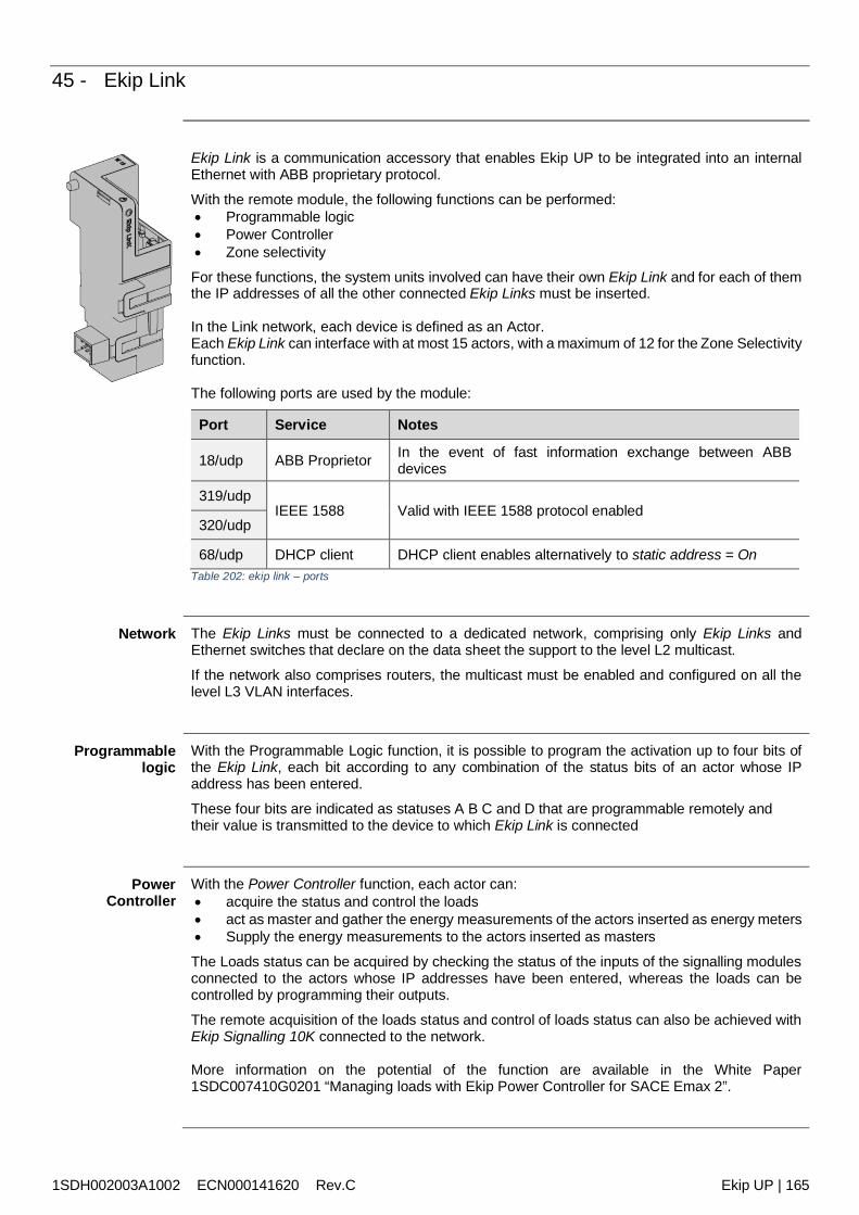
1SDH002003A1002 ECN000141620 Rev.C Ekip UP | 165
45 - Ekip Link
Ekip Link is a communication accessory that enables Ekip UP to be integrated into an internalEthernet with ABB proprietary protocol.
With the remote module, the following functions can be performed: Programmable logic Power Controller Zone selectivity
For these functions, the system units involved can have their own Ekip Link and for each of themthe IP addresses of all the other connected Ekip Links must be inserted.
In the Link network, each device is defined as an Actor.Each Ekip Link can interface with at most 15 actors, with a maximum of 12 for the Zone Selectivityfunction.
The following ports are used by the module:
Port Service Notes
18/udp ABB Proprietor In the event of fast information exchange between ABBdevices
319/udpIEEE 1588 Valid with IEEE 1588 protocol enabled
320/udp
68/udp DHCP client DHCP client enables alternatively to static address = OnTable 202: ekip link – ports
Network The Ekip Links must be connected to a dedicated network, comprising only Ekip Links andEthernet switches that declare on the data sheet the support to the level L2 multicast.
If the network also comprises routers, the multicast must be enabled and configured on all thelevel L3 VLAN interfaces.
Programmablelogic
With the Programmable Logic function, it is possible to program the activation up to four bits ofthe Ekip Link, each bit according to any combination of the status bits of an actor whose IPaddress has been entered.
These four bits are indicated as statuses A B C and D that are programmable remotely andtheir value is transmitted to the device to which Ekip Link is connected
PowerController
With the Power Controller function, each actor can: acquire the status and control the loads act as master and gather the energy measurements of the actors inserted as energy meters Supply the energy measurements to the actors inserted as masters
The Loads status can be acquired by checking the status of the inputs of the signalling modulesconnected to the actors whose IP addresses have been entered, whereas the loads can becontrolled by programming their outputs.
The remote acquisition of the loads status and control of loads status can also be achieved withEkip Signalling 10K connected to the network.
More information on the potential of the function are available in the White Paper1SDC007410G0201 “Managing loads with Ekip Power Controller for SACE Emax 2”.
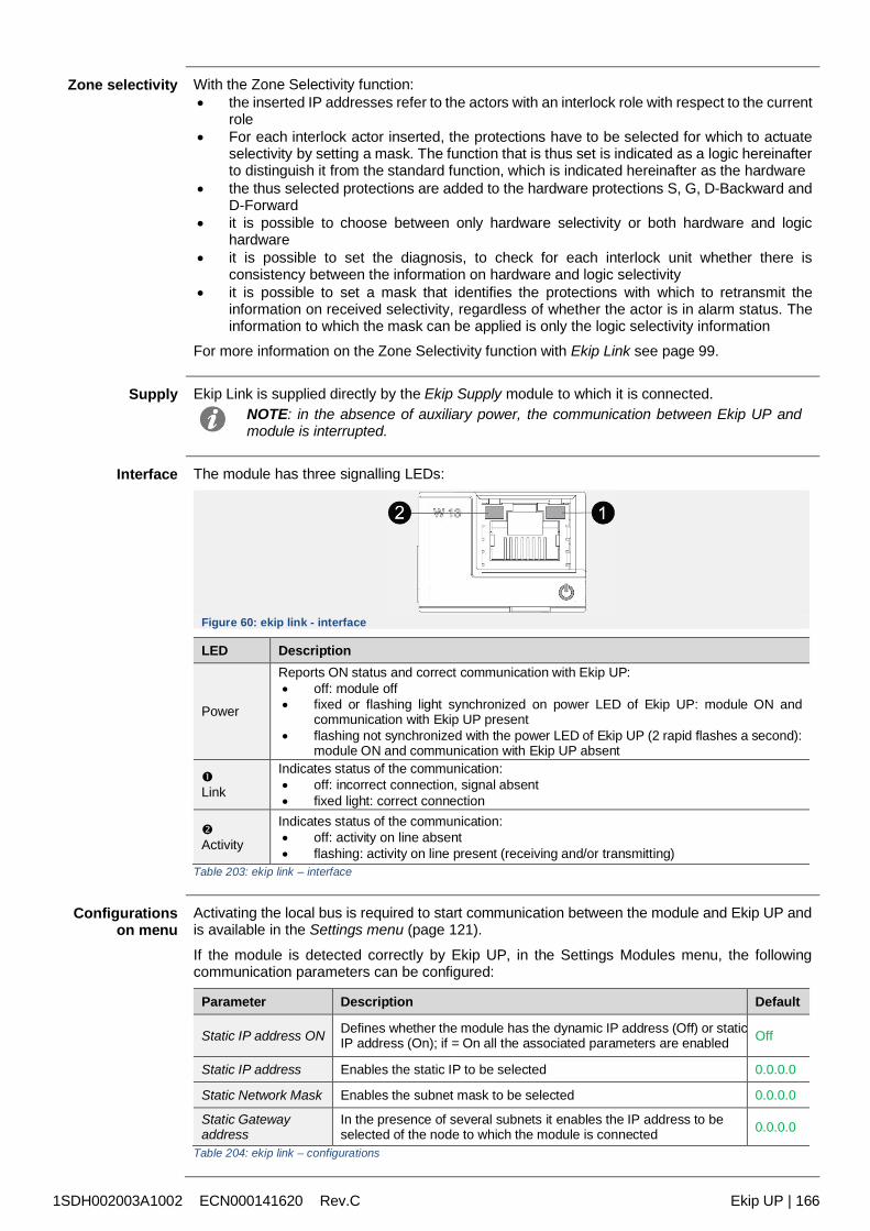
1SDH002003A1002 ECN000141620 Rev.C Ekip UP | 166
Zone selectivity With the Zone Selectivity function: the inserted IP addresses refer to the actors with an interlock role with respect to the current
role For each interlock actor inserted, the protections have to be selected for which to actuate
selectivity by setting a mask. The function that is thus set is indicated as a logic hereinafterto distinguish it from the standard function, which is indicated hereinafter as the hardware
the thus selected protections are added to the hardware protections S, G, D-Backward andD-Forward
it is possible to choose between only hardware selectivity or both hardware and logichardware
it is possible to set the diagnosis, to check for each interlock unit whether there isconsistency between the information on hardware and logic selectivity
it is possible to set a mask that identifies the protections with which to retransmit theinformation on received selectivity, regardless of whether the actor is in alarm status. Theinformation to which the mask can be applied is only the logic selectivity information
For more information on the Zone Selectivity function with Ekip Link see page 99.
Supply Ekip Link is supplied directly by the Ekip Supply module to which it is connected.NOTE: in the absence of auxiliary power, the communication between Ekip UP andmodule is interrupted.
Interface The module has three signalling LEDs:
Figure 60: ekip link - interface
LED Description
Power
Reports ON status and correct communication with Ekip UP: off: module off fixed or flashing light synchronized on power LED of Ekip UP: module ON and
communication with Ekip UP present flashing not synchronized with the power LED of Ekip UP (2 rapid flashes a second):
module ON and communication with Ekip UP absent
Link
Indicates status of the communication: off: incorrect connection, signal absent fixed light: correct connection
Activity
Indicates status of the communication: off: activity on line absent flashing: activity on line present (receiving and/or transmitting)
Table 203: ekip link – interface
Configurationson menu
Activating the local bus is required to start communication between the module and Ekip UP andis available in the Settings menu (page 121).
If the module is detected correctly by Ekip UP, in the Settings Modules menu, the followingcommunication parameters can be configured:
Parameter Description Default
Static IP address ON Defines whether the module has the dynamic IP address (Off) or staticIP address (On); if = On all the associated parameters are enabled Off
Static IP address Enables the static IP to be selected 0.0.0.0
Static Network Mask Enables the subnet mask to be selected 0.0.0.0
Static Gatewayaddress
In the presence of several subnets it enables the IP address to beselected of the node to which the module is connected 0.0.0.0
Table 204: ekip link – configurations
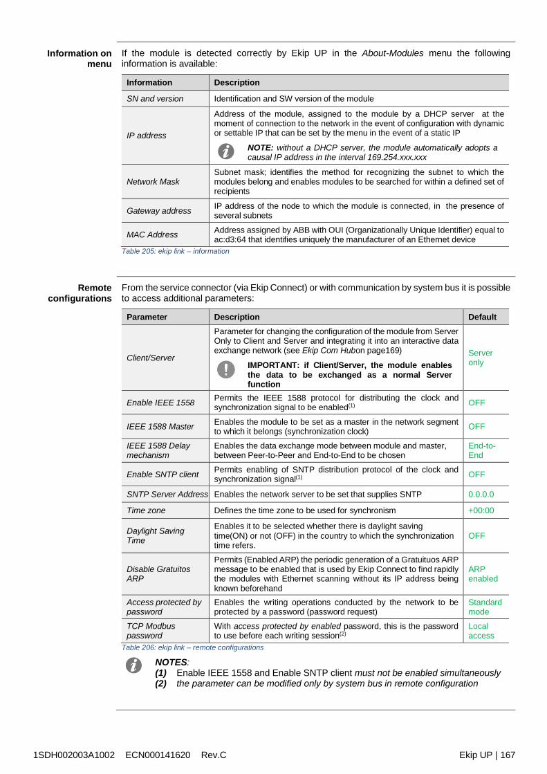
1SDH002003A1002 ECN000141620 Rev.C Ekip UP | 167
Information onmenu
If the module is detected correctly by Ekip UP in the About-Modules menu the followinginformation is available:
Information Description
SN and version Identification and SW version of the module
IP address
Address of the module, assigned to the module by a DHCP server at themoment of connection to the network in the event of configuration with dynamicor settable IP that can be set by the menu in the event of a static IP
NOTE: without a DHCP server, the module automatically adopts acausal IP address in the interval 169.254.xxx.xxx
Network MaskSubnet mask; identifies the method for recognizing the subnet to which themodules belong and enables modules to be searched for within a defined set ofrecipients
Gateway address IP address of the node to which the module is connected, in the presence ofseveral subnets
MAC Address Address assigned by ABB with OUI (Organizationally Unique Identifier) equal toac:d3:64 that identifies uniquely the manufacturer of an Ethernet device
Table 205: ekip link – information
Remoteconfigurations
From the service connector (via Ekip Connect) or with communication by system bus it is possibleto access additional parameters:
Parameter Description Default
Client/Server
Parameter for changing the configuration of the module from ServerOnly to Client and Server and integrating it into an interactive dataexchange network (see Ekip Com Hubon page169)
IMPORTANT: if Client/Server, the module enablesthe data to be exchanged as a normal Serverfunction
Serveronly
Enable IEEE 1558 Permits the IEEE 1588 protocol for distributing the clock andsynchronization signal to be enabled(1) OFF
IEEE 1588 Master Enables the module to be set as a master in the network segmentto which it belongs (synchronization clock) OFF
IEEE 1588 Delaymechanism
Enables the data exchange mode between module and master,between Peer-to-Peer and End-to-End to be chosen
End-to-End
Enable SNTP client Permits enabling of SNTP distribution protocol of the clock andsynchronization signal(1) OFF
SNTP Server Address Enables the network server to be set that supplies SNTP 0.0.0.0
Time zone Defines the time zone to be used for synchronism +00:00
Daylight SavingTime
Enables it to be selected whether there is daylight savingtime(ON) or not (OFF) in the country to which the synchronizationtime refers.
OFF
Disable GratuitosARP
Permits (Enabled ARP) the periodic generation of a Gratuituos ARPmessage to be enabled that is used by Ekip Connect to find rapidlythe modules with Ethernet scanning without its IP address beingknown beforehand
ARPenabled
Access protected bypassword
Enables the writing operations conducted by the network to beprotected by a password (password request)
Standardmode
TCP Modbuspassword
With access protected by enabled password, this is the passwordto use before each writing session(2)
Localaccess
Table 206: ekip link – remote configurations
NOTES:(1) Enable IEEE 1558 and Enable SNTP client must not be enabled simultaneously(2) the parameter can be modified only by system bus in remote configuration
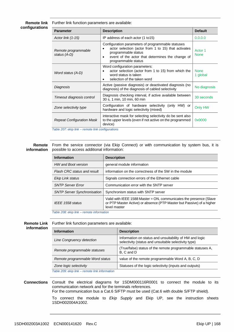
1SDH002003A1002 ECN000141620 Rev.C Ekip UP | 168
Remote linkconfigurations
Further link function parameters are available:
Parameter Description Default
Actor link (1-15) IP address of each actor (1 to15) 0.0.0.0
Remote programmablestatus (A-D)
Configuration parameters of programmable statuses actor selection (actor from 1 to 15) that activates
programmable status event of the actor that determines the change of
programmable status
Actor 1None
Word status (A-D)
Word configuration parameters: actor selection (actor from 1 to 15) from which the
word status is taken selection of the taken word
None1 global
Diagnosis Active (passive diagnosis) or deactivated diagnosis (nodiagnosis) of the diagnosis of cabled selectivity No diagnosis
Timeout diagnosis control Diagnosis checking interval, if active available between30 s, 1 min, 10 min, 60 min 30 seconds
Zone selectivity type Configuration of hardware selectivity (only HW) orhardware and logic selectivity (mixed) Only HW
Repeat Configuration Maskinteractive mask for selecting selectivity do be sent alsoto the upper levels (even if not active on the programmeddevice)
0x0000
Table 207: ekip link – remote link configurations
Remoteinformation
From the service connector (via Ekip Connect) or with communication by system bus, it ispossible to access additional information:
Information Description
HW and Boot version general module information
Flash CRC status and result information on the correctness of the SW in the module
Ekip Link status Signals connection errors of the Ethernet cable
SNTP Server Error Communication error with the SNTP server
SNTP Server Synchronisation Synchronism status with SNTP server
IEEE 1558 statusValid with IEEE 1588 Master = ON, communicates the presence (Slaveor PTP Master Active) or absence (PTP Master but Passive) of a higherlevel master
Table 208: ekip link – remote information
Remote Linkinformation
Further link function parameters are available:
Information Description
Line Congruency detection Information on status and unsuitability of HW and logicselectivity (status and unsuitable selectivity type)
Remote programmable statuses (True/false) status of the remote programmable statuses A,B, C and D
Remote programmable Word status value of the remote programmable Word A, B, C, D
Zone logic selectivity Statuses of the logic selectivity (inputs and outputs)Table 209: ekip link – remote link information
Connections Consult the electrical diagrams for 1SDM000116R0001 to connect the module to itscommunication network and for the terminals references.For the communication bus a Cat.6 S/FTP must be used (Cat.6 with double S/FTP shield).
To connect the module to Ekip Supply and Ekip UP, see the instruction sheets1SDH002004A1002.
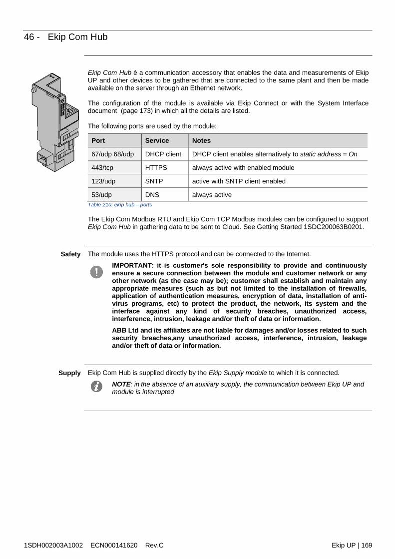
1SDH002003A1002 ECN000141620 Rev.C Ekip UP | 169
46 - Ekip Com Hub
Ekip Com Hub è a communication accessory that enables the data and measurements of EkipUP and other devices to be gathered that are connected to the same plant and then be madeavailable on the server through an Ethernet network.
The configuration of the module is available via Ekip Connect or with the System Interfacedocument (page 173) in which all the details are listed.
The following ports are used by the module:
Port Service Notes
67/udp 68/udp DHCP client DHCP client enables alternatively to static address = On
443/tcp HTTPS always active with enabled module
123/udp SNTP active with SNTP client enabled
53/udp DNS always activeTable 210: ekip hub – ports
The Ekip Com Modbus RTU and Ekip Com TCP Modbus modules can be configured to supportEkip Com Hub in gathering data to be sent to Cloud. See Getting Started 1SDC200063B0201.
Safety The module uses the HTTPS protocol and can be connected to the Internet.
IMPORTANT: it is customer's sole responsibility to provide and continuouslyensure a secure connection between the module and customer network or anyother network (as the case may be); customer shall establish and maintain anyappropriate measures (such as but not limited to the installation of firewalls,application of authentication measures, encryption of data, installation of anti-virus programs, etc) to protect the product, the network, its system and theinterface against any kind of security breaches, unauthorized access,interference, intrusion, leakage and/or theft of data or information.ABB Ltd and its affiliates are not liable for damages and/or losses related to suchsecurity breaches,any unauthorized access, interference, intrusion, leakageand/or theft of data or information.
Supply Ekip Com Hub is supplied directly by the Ekip Supply module to which it is connected.
NOTE: in the absence of an auxiliary supply, the communication between Ekip UP andmodule is interrupted
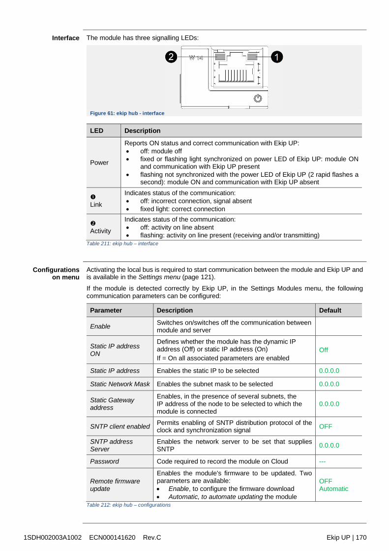
1SDH002003A1002 ECN000141620 Rev.C Ekip UP | 170
Interface The module has three signalling LEDs:
Figure 61: ekip hub - interface
LED Description
Power
Reports ON status and correct communication with Ekip UP: off: module off fixed or flashing light synchronized on power LED of Ekip UP: module ON
and communication with Ekip UP present flashing not synchronized with the power LED of Ekip UP (2 rapid flashes a
second): module ON and communication with Ekip UP absent
Link
Indicates status of the communication: off: incorrect connection, signal absent fixed light: correct connection
Activity
Indicates status of the communication: off: activity on line absent flashing: activity on line present (receiving and/or transmitting)
Table 211: ekip hub – interface
Configurationson menu
Activating the local bus is required to start communication between the module and Ekip UP andis available in the Settings menu (page 121).
If the module is detected correctly by Ekip UP, in the Settings Modules menu, the followingcommunication parameters can be configured:
Parameter Description Default
Enable Switches on/switches off the communication betweenmodule and server
Static IP addressON
Defines whether the module has the dynamic IPaddress (Off) or static IP address (On)If = On all associated parameters are enabled
Off
Static IP address Enables the static IP to be selected 0.0.0.0
Static Network Mask Enables the subnet mask to be selected 0.0.0.0
Static Gatewayaddress
Enables, in the presence of several subnets, theIP address of the node to be selected to which themodule is connected
0.0.0.0
SNTP client enabled Permits enabling of SNTP distribution protocol of theclock and synchronization signal OFF
SNTP addressServer
Enables the network server to be set that suppliesSNTP 0.0.0.0
Password Code required to record the module on Cloud ---
Remote firmwareupdate
Enables the module's firmware to be updated. Twoparameters are available: Enable, to configure the firmware download Automatic, to automate updating the module
OFFAutomatic
Table 212: ekip hub – configurations
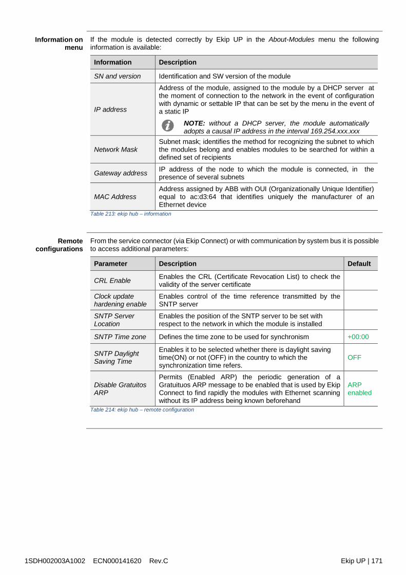
1SDH002003A1002 ECN000141620 Rev.C Ekip UP | 171
Information onmenu
If the module is detected correctly by Ekip UP in the About-Modules menu the followinginformation is available:
Information Description
SN and version Identification and SW version of the module
IP address
Address of the module, assigned to the module by a DHCP server atthe moment of connection to the network in the event of configurationwith dynamic or settable IP that can be set by the menu in the event ofa static IP
NOTE: without a DHCP server, the module automaticallyadopts a causal IP address in the interval 169.254.xxx.xxx
Network MaskSubnet mask; identifies the method for recognizing the subnet to whichthe modules belong and enables modules to be searched for within adefined set of recipients
Gateway address IP address of the node to which the module is connected, in thepresence of several subnets
MAC AddressAddress assigned by ABB with OUI (Organizationally Unique Identifier)equal to ac:d3:64 that identifies uniquely the manufacturer of anEthernet device
Table 213: ekip hub – information
Remoteconfigurations
From the service connector (via Ekip Connect) or with communication by system bus it is possibleto access additional parameters:
Parameter Description Default
CRL Enable Enables the CRL (Certificate Revocation List) to check thevalidity of the server certificate
Clock updatehardening enable
Enables control of the time reference transmitted by theSNTP server
SNTP ServerLocation
Enables the position of the SNTP server to be set withrespect to the network in which the module is installed
SNTP Time zone Defines the time zone to be used for synchronism +00:00
SNTP DaylightSaving Time
Enables it to be selected whether there is daylight savingtime(ON) or not (OFF) in the country to which thesynchronization time refers.
OFF
Disable GratuitosARP
Permits (Enabled ARP) the periodic generation of aGratuituos ARP message to be enabled that is used by EkipConnect to find rapidly the modules with Ethernet scanningwithout its IP address being known beforehand
ARPenabled
Table 214: ekip hub – remote configuration
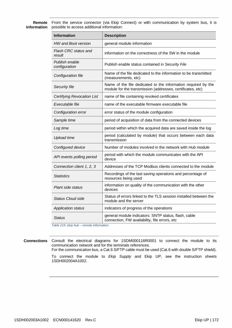
1SDH002003A1002 ECN000141620 Rev.C Ekip UP | 172
Remoteinformation
From the service connector (via Ekip Connect) or with communication by system bus, it ispossible to access additional information:
Information Description
HW and Boot version general module information
Flash CRC status andresult information on the correctness of the SW in the module
Publish enableconfiguration Publish enable status contained in Security File
Configuration file Name of the file dedicated to the information to be transmitted(measurements, etc)
Security file Name of the file dedicated to the information required by themodule for the transmission (addresses, certificates, etc)
Certifying Revocation List name of file containing revoked certificates
Executable file name of the executable firmware executable file
Configuration error error status of the module configuration
Sample time period of acquisition of data from the connected devices
Log time period within which the acquired data are saved inside the log
Upload time period (calculated by module) that occurs between each datatransmission
Configured device Number of modules involved in the network with Hub module
API events polling period period with which the module communicates with the APIdevice
Connection client 1, 2, 3 Addresses of the TCP Modbus clients connected to the module
Statistics Recordings of the last saving operations and percentage ofresources being used
Plant side status information on quality of the communication with the otherdevices
Status Cloud side Status of errors linked to the TLS session installed between themodule and the server
Application status indicators of progress of the operations
Status general module indicators: SNTP status, flash, cableconnection, FW availability, file errors, etc
Table 215: ekip hub – remote information
Connections Consult the electrical diagrams for 1SDM000116R0001 to connect the module to itscommunication network and for the terminals references.For the communication bus, a Cat.6 S/FTP cable must be used (Cat.6 with double S/FTP shield).
To connect the module to Ekip Supply and Ekip UP, see the instruction sheets1SDH002004A1002.
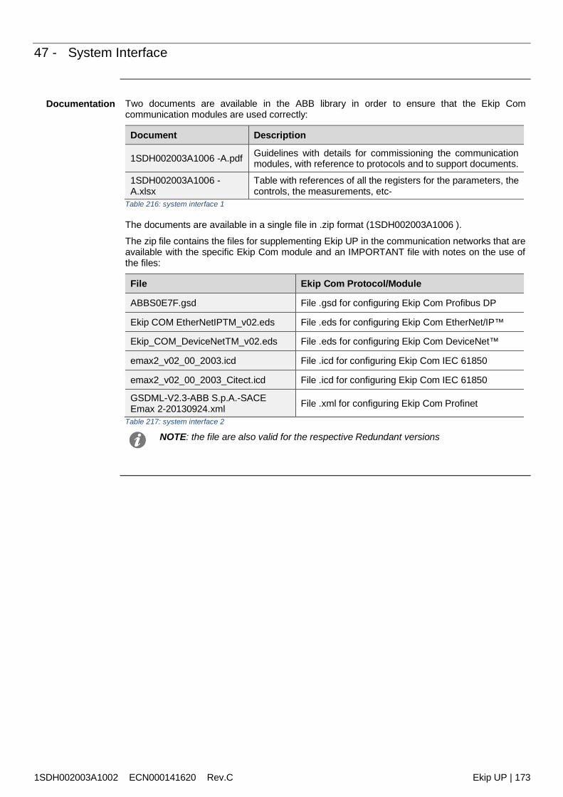
1SDH002003A1002 ECN000141620 Rev.C Ekip UP | 173
47 - System Interface
Documentation Two documents are available in the ABB library in order to ensure that the Ekip Comcommunication modules are used correctly:
Document Description
1SDH002003A1006 -A.pdf Guidelines with details for commissioning the communicationmodules, with reference to protocols and to support documents.
1SDH002003A1006 -A.xlsx
Table with references of all the registers for the parameters, thecontrols, the measurements, etc-
Table 216: system interface 1
The documents are available in a single file in .zip format (1SDH002003A1006 ).
The zip file contains the files for supplementing Ekip UP in the communication networks that areavailable with the specific Ekip Com module and an IMPORTANT file with notes on the use ofthe files:
File Ekip Com Protocol/Module
ABBS0E7F.gsd File .gsd for configuring Ekip Com Profibus DP
Ekip COM EtherNetIPTM_v02.eds File .eds for configuring Ekip Com EtherNet/IP™
Ekip_COM_DeviceNetTM_v02.eds File .eds for configuring Ekip Com DeviceNet™
emax2_v02_00_2003.icd File .icd for configuring Ekip Com IEC 61850
emax2_v02_00_2003_Citect.icd File .icd for configuring Ekip Com IEC 61850
GSDML-V2.3-ABB S.p.A.-SACEEmax 2-20130924.xml File .xml for configuring Ekip Com Profinet
Table 217: system interface 2
NOTE: the file are also valid for the respective Redundant versions
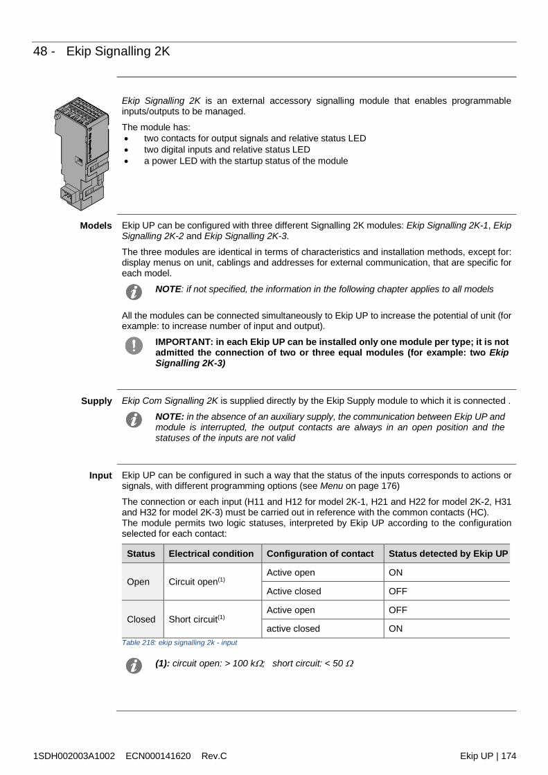
1SDH002003A1002 ECN000141620 Rev.C Ekip UP | 174
48 - Ekip Signalling 2K
Ekip Signalling 2K is an external accessory signalling module that enables programmableinputs/outputs to be managed.
The module has: two contacts for output signals and relative status LED two digital inputs and relative status LED a power LED with the startup status of the module
Models Ekip UP can be configured with three different Signalling 2K modules: Ekip Signalling 2K-1, EkipSignalling 2K-2 and Ekip Signalling 2K-3.
The three modules are identical in terms of characteristics and installation methods, except for:display menus on unit, cablings and addresses for external communication, that are specific foreach model.
NOTE: if not specified, the information in the following chapter applies to all models
All the modules can be connected simultaneously to Ekip UP to increase the potential of unit (forexample: to increase number of input and output).
IMPORTANT: in each Ekip UP can be installed only one module per type; it is notadmitted the connection of two or three equal modules (for example: two EkipSignalling 2K-3)
Supply Ekip Com Signalling 2K is supplied directly by the Ekip Supply module to which it is connected .
NOTE: in the absence of an auxiliary supply, the communication between Ekip UP andmodule is interrupted, the output contacts are always in an open position and thestatuses of the inputs are not valid
Input Ekip UP can be configured in such a way that the status of the inputs corresponds to actions orsignals, with different programming options (see Menu on page 176)
The connection or each input (H11 and H12 for model 2K-1, H21 and H22 for model 2K-2, H31and H32 for model 2K-3) must be carried out in reference with the common contacts (HC).The module permits two logic statuses, interpreted by Ekip UP according to the configurationselected for each contact:
Status Electrical condition Configuration of contact Status detected by Ekip UP
Open Circuit open(1)Active open ON
Active closed OFF
Closed Short circuit(1)Active open OFF
active closed ONTable 218: ekip signalling 2k - input
(1): circuit open: > 100 k; short circuit: < 50
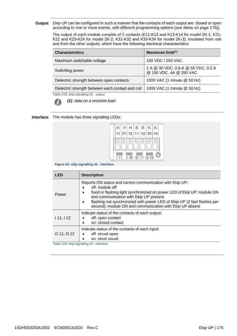
1SDH002003A1002 ECN000141620 Rev.C Ekip UP | 175
Output Ekip UP can be configured in such a manner that the contacts of each output are closed or openaccording to one or more events, with different programming options (see Menu on page 176)).
The output of each module consists of 2 contacts (K11-K12 and K13-K14 for model 2K-1; K21-K22 and K23-K24 for model 2K-2; K31-K32 and K33-K34 for model 2K-3), insulated from unitand from the other outputs, which have the following electrical characteristics:
Characteristics Maximum limit(1)
Maximum switchable voltage 150 VDC / 250 VAC.
Switching power 2 A @ 30 VDC, 0.8 A @ 50 VDC, 0.2 A@ 150 VDC, 4A @ 250 VAC
Dielectric strength between open contacts 1000 VAC (1 minute @ 50 Hz)
Dielectric strength between each contact and coil 1000 VAC (1 minute @ 50 Hz)Table 219: ekip signalling 2k - output
(1): data on a resistive load
Interface The module has three signalling LEDs:
Figure 62: ekip signalling 2k - interface
LED Description
Power
Reports ON status and correct communication with Ekip UP: off: module off fixed or flashing light synchronized on power LED of Ekip UP: module ON
and communication with Ekip UP present flashing not synchronized with power LED of Ekip UP (2 fast flashes per
second): module ON and communication with Ekip UP absent
I 11, I 12Indicate status of the contacts of each output: off: open contact on: closed contact
O 11, O 12Indicate status of the contacts of each input: off: circuit open on: short circuit
Table 220: ekip signalling 2k - interface
1SDH002003A1002 ECN000141620 Rev.C Ekip UP | 176
Menu If the Ekip Signalling 2K module is detected correctly by Ekip UP the specific configuration areain the Modules Settings menu is activated.
For each Ekip Signalling 2K module detected by Ekip UP, a specific menu is available containingthe submenus of all the available and configurable inputs and outputs.
InputParameters
All the available inputs enable the following parameters to be configured:
Parameter Description Default
Polarity Defines whether the input is defined as ON by Ekip UP when itis open (Active open) or when it is closed (Active Closed)
Activeclosed
Delay
Minimum duration of activation of the input before the statuschange is recognized; the delay is expressed in seconds, whichare settable in a range: 0 s - 100 s with 0.01 s step
NOTE: if the source is deactivated before this time has
elapsed the status change is not recognized with delay = 0 s the status change must be
anyway greater than 300 S
0.1 s
Table 221: ekip signalling 2k – input parameters
ParametersOutput Parameter Description Default
Signal source
Event that activates the output and switches the contact.
On the display, different protection proposals, statuses andthresholds are available; via Ekip Connect the Custom modecan be configured to extend the solutions and combine severalevents.
None
Delay
Minimum duration of presence of the source before the outputis activated; the delay is expressed in seconds, which aresettable in a range: 0 s - 100 s with 0.01 s step
NOTE: if the source is deactivated before this time the
output is not switched with delay = 0 s the source must be anyway
present for more than 300 S
0 s
Contact type Defines the rest status of the contact with a non-present sourcebetween: open (NO) and closed (NC) NO
Latched(1) Enables the output (and relative status LED) to be maintainedactive (ON) or be deactivated (OFF) until the event disappears. Off
Activation timeMinimum(1)
Defines the minimum closure time of the contact following therapid presence of sources: Source duration < min. activation= the contact is activated
for the minimum activation time Source duration min. activation=the contact is activated
for as long as the source persists
It is possible to choose between: 0 ms, 100 ms, 200 ms
0 ms
Table 222: ekip signalling 2k – output parameters
(1): if Ekip Measuring is used for the Power Controller function, the followingconsiderations apply: Latched: deactivate sall the Latched configuration of the outputs used for Power
Controller Minimum activation time: the Power Controller option is available in addition to
those that have already been described: if selected, the output and active latchingis active for a set time that depends on the function, regardless of the persistenceof the event that activated it.
1SDH002003A1002 ECN000141620 Rev.C Ekip UP | 177
Information In the About-Modules menu the specific menu of the module is available that contains: the serial number and the version of the module the status of the inputs (On/Off) and of the outputs (Open/Closed)
Test If the Ekip Signalling 2K module is detected correctly, the test area in the Test menu is activated.
For details of test characteristics, see page 126.
Remoteinformation
From the service connector (via Ekip Connect) or with a system bus communication, additionalinformation is available on the version and the status of the module: HW and Boot version, CRCstatus (correctness of SW in the module).
Test If the Ekip Signalling 2K module is detected correctly, the test area in the Test menu is activated.
For details of test characteristics, see page 125.
Connections Consult the electrical diagrams for 1SDM000116R0001 to connect the module to itscommunication network and for terminal references.For external cabling, AWG 22-16 cables with a maximum external diameter of 1.4 mm must beused
To connect the module to Ekip Supply and Ekip UP, see the instruction sheets1SDH002004A1002.
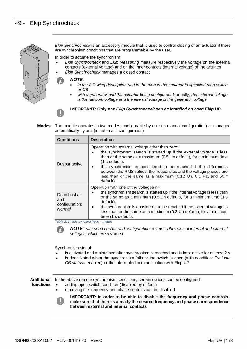
1SDH002003A1002 ECN000141620 Rev.C Ekip UP | 178
49 - Ekip Synchrocheck
Ekip Synchrocheck is an accessory module that is used to control closing of an actuator if thereare synchronism conditions that are programmable by the user.
In order to actuate the synchronism: Ekip Synchrocheck and Ekip Measuring measure respectively the voltage on the external
contacts (external voltage) and on the inner contacts (internal voltage) of the actuator Ekip Synchrocheck manages a closed contact
NOTE: in the following description and in the menus the actuator is specified as a switch
or CB with a generator and the actuator being configured: Normally, the external voltage
is the network voltage and the internal voltage is the generator voltage
IMPORTANT: Only one Ekip Synchrocheck can be installed on each Ekip UP
Modes The module operates in two modes, configurable by user (in manual configuration) or managedautomatically by unit (in automatic configuration)
Conditions Description
Busbar active
Operation with external voltage other than zero: the synchronism search is started up if the external voltage is less
than or the same as a maximum (0.5 Un default), for a minimum time(1 s default).
the synchronism is considered to be reached if the differencesbetween the RMS values, the frequencies and the voltage phases areless than or the same as a maximum (0.12 Un, 0.1 Hz, and 50 °default)
Dead busbarandconfiguration:Normal
Operation with one of the voltages nil: the synchronism search is started up if the internal voltage is less than
or the same as a minimum (0.5 Un default), for a minimum time (1 sdefault).
the synchronism is considered to be reached if the external voltage isless than or the same as a maximum (0.2 Un default), for a minimumtime (1 s default).
Table 223: ekip synchrocheck – modes
NOTE: with dead busbar and configuration: reverses the roles of internal and externalvoltages, which are reversed
Synchronism signal: is activated and maintained after synchronism is reached and is kept active for at least 2 s is deactivated when the synchronism falls or the switch is open (with condition: Evaluate
CB status= enabled) or the interrupted communication with Ekip UP
Additionalfunctions
In the above remote synchronism conditions, certain options can be configured: adding open switch condition (disabled by default) removing the frequency and phase controls can be disabled
IMPORTANT: in order to be able to disable the frequency and phase controls,make sure that there is already the desired frequency and phase correspondencebetween external and internal contacts
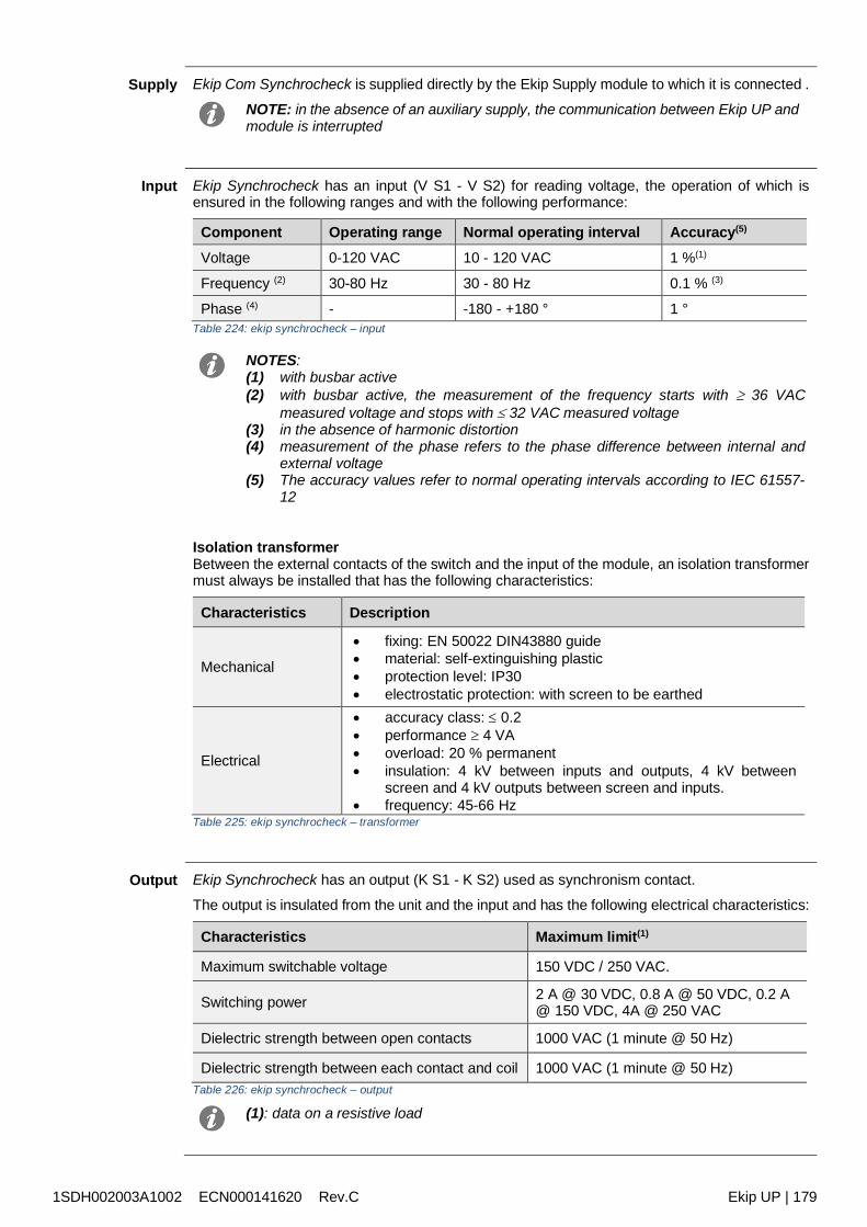
1SDH002003A1002 ECN000141620 Rev.C Ekip UP | 179
Supply Ekip Com Synchrocheck is supplied directly by the Ekip Supply module to which it is connected .
NOTE: in the absence of an auxiliary supply, the communication between Ekip UP andmodule is interrupted
Input Ekip Synchrocheck has an input (V S1 - V S2) for reading voltage, the operation of which isensured in the following ranges and with the following performance:
Component Operating range Normal operating interval Accuracy(5)
Voltage 0-120 VAC 10 - 120 VAC 1 %(1)
Frequency (2) 30-80 Hz 30 - 80 Hz 0.1 % (3)
Phase (4) - -180 - +180 ° 1 °Table 224: ekip synchrocheck – input
NOTES:(1) with busbar active(2) with busbar active, the measurement of the frequency starts with 36 VAC
measured voltage and stops with 32 VAC measured voltage(3) in the absence of harmonic distortion(4) measurement of the phase refers to the phase difference between internal and
external voltage(5) The accuracy values refer to normal operating intervals according to IEC 61557-
12
Isolation transformerBetween the external contacts of the switch and the input of the module, an isolation transformermust always be installed that has the following characteristics:
Characteristics Description
Mechanical
fixing: EN 50022 DIN43880 guide material: self-extinguishing plastic protection level: IP30 electrostatic protection: with screen to be earthed
Electrical
accuracy class: 0.2 performance 4 VA overload: 20 % permanent insulation: 4 kV between inputs and outputs, 4 kV between
screen and 4 kV outputs between screen and inputs. frequency: 45-66 Hz
Table 225: ekip synchrocheck – transformer
Output Ekip Synchrocheck has an output (K S1 - K S2) used as synchronism contact.
The output is insulated from the unit and the input and has the following electrical characteristics:
Characteristics Maximum limit(1)
Maximum switchable voltage 150 VDC / 250 VAC.
Switching power 2 A @ 30 VDC, 0.8 A @ 50 VDC, 0.2 A@ 150 VDC, 4A @ 250 VAC
Dielectric strength between open contacts 1000 VAC (1 minute @ 50 Hz)
Dielectric strength between each contact and coil 1000 VAC (1 minute @ 50 Hz)Table 226: ekip synchrocheck – output
(1): data on a resistive load
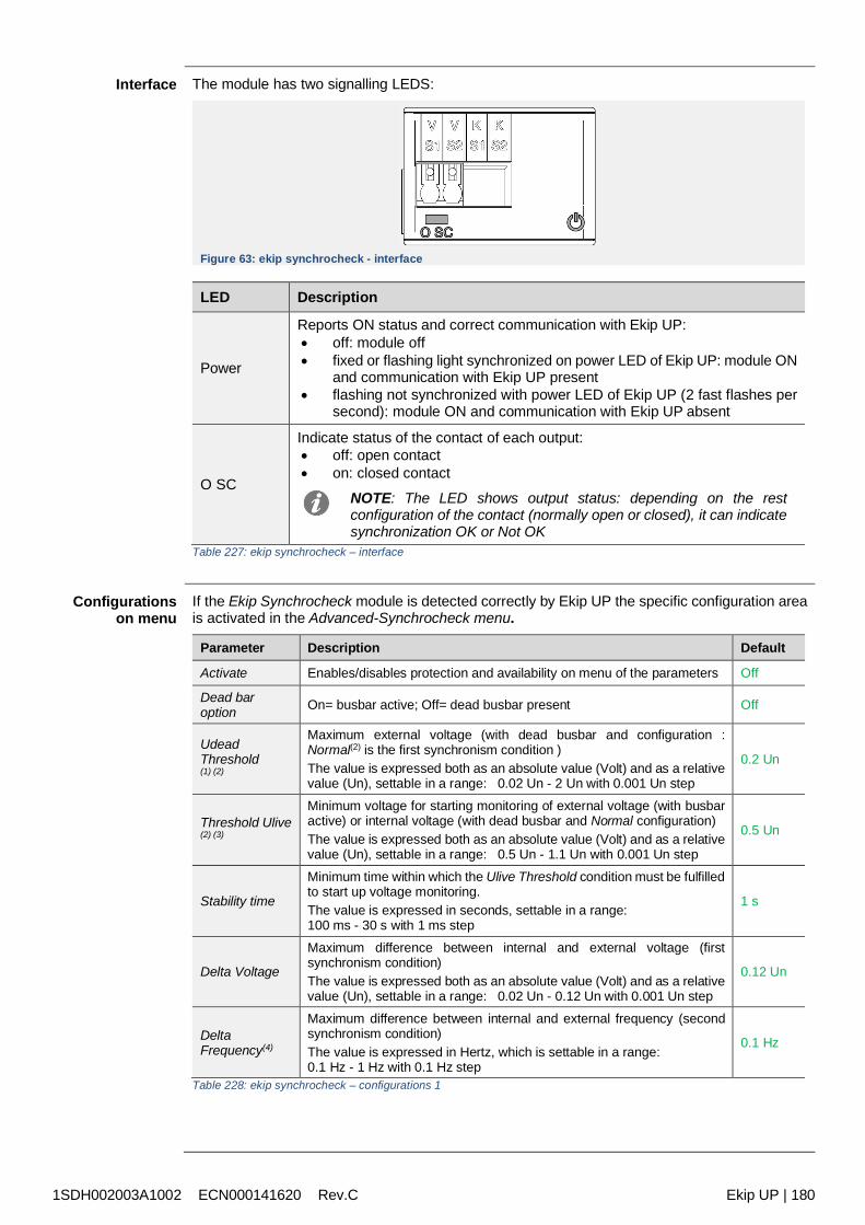
1SDH002003A1002 ECN000141620 Rev.C Ekip UP | 180
Interface The module has two signalling LEDS:
Figure 63: ekip synchrocheck - interface
LED Description
Power
Reports ON status and correct communication with Ekip UP: off: module off fixed or flashing light synchronized on power LED of Ekip UP: module ON
and communication with Ekip UP present flashing not synchronized with power LED of Ekip UP (2 fast flashes per
second): module ON and communication with Ekip UP absent
O SC
Indicate status of the contact of each output: off: open contact on: closed contact
NOTE: The LED shows output status: depending on the restconfiguration of the contact (normally open or closed), it can indicatesynchronization OK or Not OK
Table 227: ekip synchrocheck – interface
Configurationson menu
If the Ekip Synchrocheck module is detected correctly by Ekip UP the specific configuration areais activated in the Advanced-Synchrocheck menu.
Parameter Description Default
Activate Enables/disables protection and availability on menu of the parameters Off
Dead baroption On= busbar active; Off= dead busbar present Off
UdeadThreshold(1) (2)
Maximum external voltage (with dead busbar and configuration :Normal(2) is the first synchronism condition )The value is expressed both as an absolute value (Volt) and as a relativevalue (Un), settable in a range: 0.02 Un - 2 Un with 0.001 Un step
0.2 Un
Threshold Ulive(2) (3)
Minimum voltage for starting monitoring of external voltage (with busbaractive) or internal voltage (with dead busbar and Normal configuration)The value is expressed both as an absolute value (Volt) and as a relativevalue (Un), settable in a range: 0.5 Un - 1.1 Un with 0.001 Un step
0.5 Un
Stability time
Minimum time within which the Ulive Threshold condition must be fulfilledto start up voltage monitoring.The value is expressed in seconds, settable in a range:100 ms - 30 s with 1 ms step
1 s
Delta Voltage
Maximum difference between internal and external voltage (firstsynchronism condition)The value is expressed both as an absolute value (Volt) and as a relativevalue (Un), settable in a range: 0.02 Un - 0.12 Un with 0.001 Un step
0.12 Un
DeltaFrequency(4)
Maximum difference between internal and external frequency (secondsynchronism condition)The value is expressed in Hertz, which is settable in a range:0.1 Hz - 1 Hz with 0.1 Hz step
0.1 Hz
Table 228: ekip synchrocheck – configurations 1
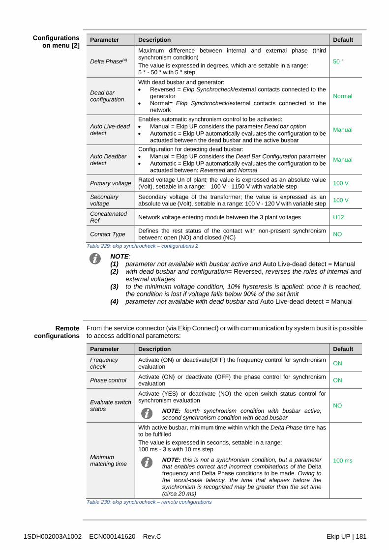
1SDH002003A1002 ECN000141620 Rev.C Ekip UP | 181
Configurationson menu [2]
Parameter Description Default
Delta Phase(4)
Maximum difference between internal and external phase (thirdsynchronism condition)The value is expressed in degrees, which are settable in a range:5 ° - 50 ° with 5 ° step
50 °
Dead barconfiguration
With dead busbar and generator: Reversed = Ekip Synchrocheck/external contacts connected to the
generator Normal= Ekip Synchrocheck/external contacts connected to the
network
Normal
Auto Live-deaddetect
Enables automatic synchronism control to be activated: Manual = Ekip UP considers the parameter Dead bar option Automatic = Ekip UP automatically evaluates the configuration to be
actuated between the dead busbar and the active busbar
Manual
Auto Deadbardetect
Configuration for detecting dead busbar: Manual = Ekip UP considers the Dead Bar Configuration parameter Automatic = Ekip UP automatically evaluates the configuration to be
actuated between: Reversed and Normal
Manual
Primary voltage Rated voltage Un of plant; the value is expressed as an absolute value(Volt), settable in a range: 100 V - 1150 V with variable step 100 V
Secondaryvoltage
Secondary voltage of the transformer; the value is expressed as anabsolute value (Volt), settable in a range: 100 V - 120 V with variable step 100 V
ConcatenatedRef Network voltage entering module between the 3 plant voltages U12
Contact Type Defines the rest status of the contact with non-present synchronismbetween: open (NO) and closed (NC) NO
Table 229: ekip synchrocheck – configurations 2
NOTE:(1) parameter not available with busbar active and Auto Live-dead detect = Manual(2) with dead busbar and configuration= Reversed, reverses the roles of internal and
external voltages(3) to the minimum voltage condition, 10% hysteresis is applied: once it is reached,
the condition is lost if voltage falls below 90% of the set limit(4) parameter not available with dead busbar and Auto Live-dead detect = Manual
Remoteconfigurations
From the service connector (via Ekip Connect) or with communication by system bus it is possibleto access additional parameters:
Parameter Description Default
Frequencycheck
Activate (ON) or deactivate(OFF) the frequency control for synchronismevaluation ON
Phase control Activate (ON) or deactivate (OFF) the phase control for synchronismevaluation ON
Evaluate switchstatus
Activate (YES) or deactivate (NO) the open switch status control forsynchronism evaluation
NOTE: fourth synchronism condition with busbar active;second synchronism condition with dead busbar
NO
Minimummatching time
With active busbar, minimum time within which the Delta Phase time hasto be fulfilledThe value is expressed in seconds, settable in a range:100 ms - 3 s with 10 ms step
NOTE: this is not a synchronism condition, but a parameterthat enables correct and incorrect combinations of the Deltafrequency and Delta Phase conditions to be made. Owing tothe worst-case latency, the time that elapses before thesynchronism is recognized may be greater than the set time(circa 20 ms)
100 ms
Table 230: ekip synchrocheck – remote configurations
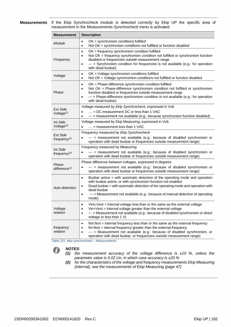
1SDH002003A1002 ECN000141620 Rev.C Ekip UP | 182
Measurements If the Ekip Synchrocheck module is detected correctly by Ekip UP the specific area ofmeasurement in the Measurements-Synchrocheck menu is activated
Measurement Description
Module OK = synchronism conditions fulfilled Not OK = synchronism conditions not fulfilled or function disabled
Frequency
OK = frequency synchronism condition fulfilled Not OK = frequency synchronism condition not fulfilled or synchronism function
disabled or frequencies outside measurement range --- = Synchronism condition for frequencies is not available (e.g.: for operation
with dead busbar)
Voltage OK = Voltage synchronism conditions fulfilled Not OK = Voltage synchronism conditions not fulfilled or function disabled
Phase
OK = Phase-difference synchronism condition fulfilled Not OK = Phase-difference synchronism condition not fulfilled or synchronism
function disabled or frequencies outside measurement range --- = Phase-difference synchronism condition is not available (e.g.: for operation
with dead busbar)
Ext SideVoltage(1)
Voltage measured by Ekip Synchrocheck, expressed in Volt .... = DC measurement DC or less than 1 VAC --- = measurement not available (e.g.: because synchronism function disabled)
Int SideVoltage(2)
Voltage measured by Ekip Measuring, expressed in Volt. .... = measurement less than 1 VAC
Ext Sidefrequency(1)
Frequency measured by Ekip Synchrocheck --- = measurement not available (e.g.: because of disabled synchronism or
operation with dead busbar or frequencies outside measurement range)
Int Sidefrequency(2)
Frequency measured by Measuring --- = measurement not available (e.g.: because of disabled synchronism or
operation with dead busbar or frequencies outside measurement range)
Phasedifference(1)
Phase difference between voltages, expressed in degrees --- = measurement not available (e.g.: because of disabled synchronism or
operation with dead busbar or frequencies outside measurement range)
Auto detection
Busbar active = with automatic detection of the operating mode and operationwith busbar active, or with synchronism function not enabled
Dead busbar = with automatic detection of the operating mode and operation withdead busbar
--- = Measurement not available (e.g.: because of manual detection of operatingmode)
Voltagerelation
VintVext = Internal voltage less than or the same as the external voltage Vin>Vext = Internal voltage greater than the external voltage --- = Measurement not available (e.g.: because of disabled synchronism or direct
voltage or less than 1 V)
frequencyrelation
fintfext = Internal frequency less than or the same as the external frequency fin>fext = internal frequency greater than the external frequency --- = Measurement not available (e.g.: because of disabled synchronism, or
operation with dead busbar, or frequencies outside measurement range)Table 231: ekip synchrocheck – Measurements
NOTES:(1) the measurement accuracy of the voltage difference is ±10 %, unless the
parameter value is 0.02 Un, in which case accuracy is ±20 %(2) for the characteristics of the voltage and frequency measurements Ekip Measuring
(internal), see the measurements of Ekip Measuring (page 47)

1SDH002003A1002 ECN000141620 Rev.C Ekip UP | 183
Summary Page The summary page is activated in the presence of the module Ekip Synchrocheck; access ispossible as for the other summary pages (page 34).
in this page, the measurements are: green if the relative synchronism condition is fulfilled red if the relative synchronism condition is not fulfilled or the function is disabled white if the measurements are not available
Information In the About-Modules menu, the specific menu of the module is available, which contains theserial number and the version of the module
Remoteinformation
From the service connector (via Ekip Connect) or with a system bus communication, additionalinformation is available on the version and the status of the module: HW and Boot version, CRCstatus (correctness of SW in the module).
Connections Consult the electrical diagrams for 1SDM000116R0001 to connect the module to itscommunication network and for terminal references.For external cabling, AWG 22-16 cables with a maximum external diameter of 1.4 mm must beused
To connect the module to Ekip Supply and Ekip UP, see the instruction sheets1SDH002004A1002.
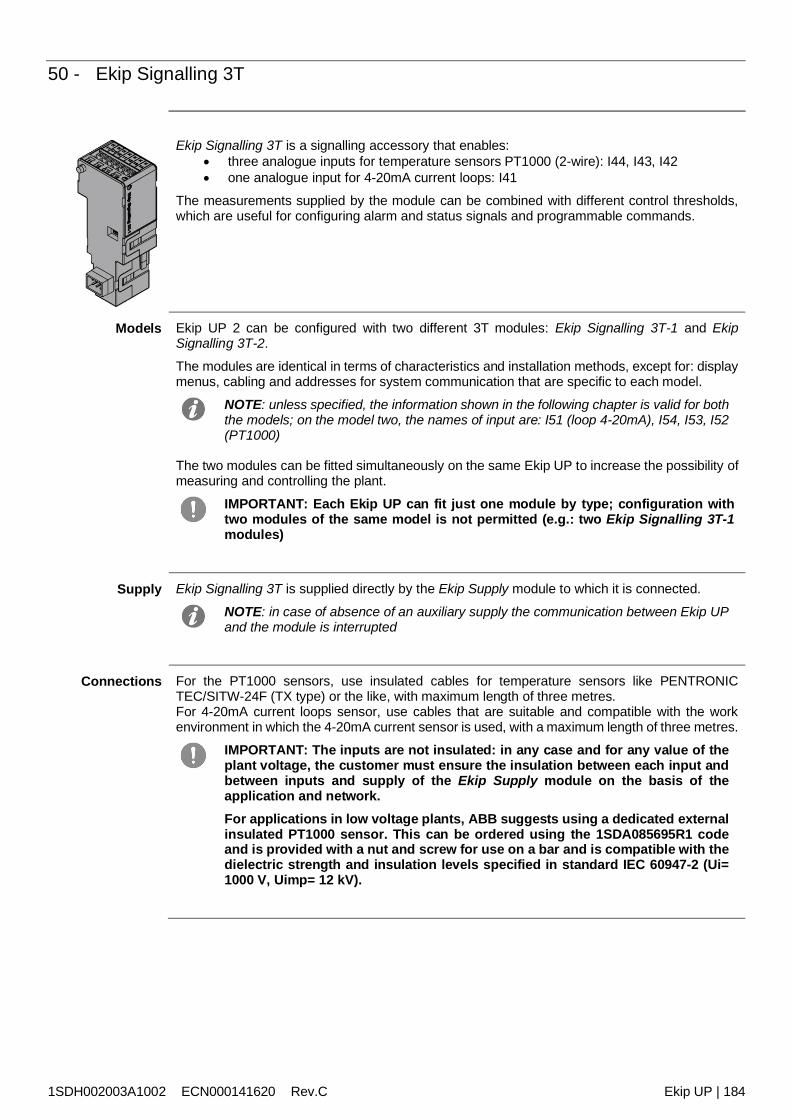
1SDH002003A1002 ECN000141620 Rev.C Ekip UP | 184
50 - Ekip Signalling 3T
Ekip Signalling 3T is a signalling accessory that enables: three analogue inputs for temperature sensors PT1000 (2-wire): I44, I43, I42 one analogue input for 4-20mA current loops: I41
The measurements supplied by the module can be combined with different control thresholds,which are useful for configuring alarm and status signals and programmable commands.
Models Ekip UP 2 can be configured with two different 3T modules: Ekip Signalling 3T-1 and EkipSignalling 3T-2.
The modules are identical in terms of characteristics and installation methods, except for: displaymenus, cabling and addresses for system communication that are specific to each model.
NOTE: unless specified, the information shown in the following chapter is valid for boththe models; on the model two, the names of input are: I51 (loop 4-20mA), I54, I53, I52(PT1000)
The two modules can be fitted simultaneously on the same Ekip UP to increase the possibility ofmeasuring and controlling the plant.
IMPORTANT: Each Ekip UP can fit just one module by type; configuration withtwo modules of the same model is not permitted (e.g.: two Ekip Signalling 3T-1modules)
Supply Ekip Signalling 3T is supplied directly by the Ekip Supply module to which it is connected.
NOTE: in case of absence of an auxiliary supply the communication between Ekip UPand the module is interrupted
Connections For the PT1000 sensors, use insulated cables for temperature sensors like PENTRONICTEC/SITW-24F (TX type) or the like, with maximum length of three metres.For 4-20mA current loops sensor, use cables that are suitable and compatible with the workenvironment in which the 4-20mA current sensor is used, with a maximum length of three metres.
IMPORTANT: The inputs are not insulated: in any case and for any value of theplant voltage, the customer must ensure the insulation between each input andbetween inputs and supply of the Ekip Supply module on the basis of theapplication and network.For applications in low voltage plants, ABB suggests using a dedicated externalinsulated PT1000 sensor. This can be ordered using the 1SDA085695R1 codeand is provided with a nut and screw for use on a bar and is compatible with thedielectric strength and insulation levels specified in standard IEC 60947-2 (Ui=1000 V, Uimp= 12 kV).
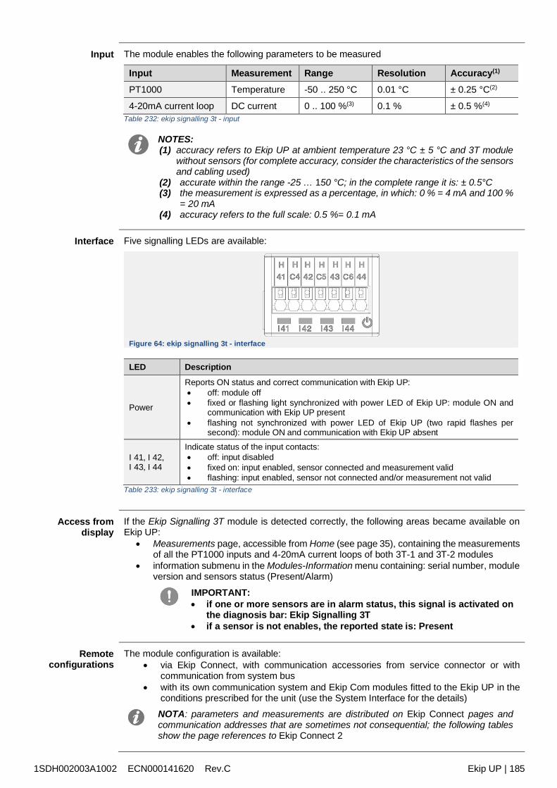
1SDH002003A1002 ECN000141620 Rev.C Ekip UP | 185
Input The module enables the following parameters to be measured
Input Measurement Range Resolution Accuracy(1)
PT1000 Temperature -50 .. 250 °C 0.01 °C ± 0.25 °C(2)
4-20mA current loop DC current 0 .. 100 %(3) 0.1 % ± 0.5 %(4)
Table 232: ekip signalling 3t - input
NOTES:(1) accuracy refers to Ekip UP at ambient temperature 23 °C ± 5 °C and 3T module
without sensors (for complete accuracy, consider the characteristics of the sensorsand cabling used)
(2) accurate within the range -25 … 150 °C; in the complete range it is: ± 0.5°C(3) the measurement is expressed as a percentage, in which: 0 % = 4 mA and 100 %
= 20 mA(4) accuracy refers to the full scale: 0.5 %= 0.1 mA
Interface Five signalling LEDs are available:
Figure 64: ekip signalling 3t - interface
LED Description
Power
Reports ON status and correct communication with Ekip UP: off: module off fixed or flashing light synchronized with power LED of Ekip UP: module ON and
communication with Ekip UP present flashing not synchronized with power LED of Ekip UP (two rapid flashes per
second): module ON and communication with Ekip UP absent
I 41, I 42,I 43, I 44
Indicate status of the input contacts: off: input disabled fixed on: input enabled, sensor connected and measurement valid flashing: input enabled, sensor not connected and/or measurement not valid
Table 233: ekip signalling 3t - interface
Access fromdisplay
If the Ekip Signalling 3T module is detected correctly, the following areas became available onEkip UP:
Measurements page, accessible from Home (see page 35), containing the measurementsof all the PT1000 inputs and 4-20mA current loops of both 3T-1 and 3T-2 modules
information submenu in the Modules-Information menu containing: serial number, moduleversion and sensors status (Present/Alarm)
IMPORTANT: if one or more sensors are in alarm status, this signal is activated on
the diagnosis bar: Ekip Signalling 3T if a sensor is not enables, the reported state is: Present
Remoteconfigurations
The module configuration is available: via Ekip Connect, with communication accessories from service connector or with
communication from system bus with its own communication system and Ekip Com modules fitted to the Ekip UP in the
conditions prescribed for the unit (use the System Interface for the details)NOTA: parameters and measurements are distributed on Ekip Connect pages andcommunication addresses that are sometimes not consequential; the following tablesshow the page references to Ekip Connect 2
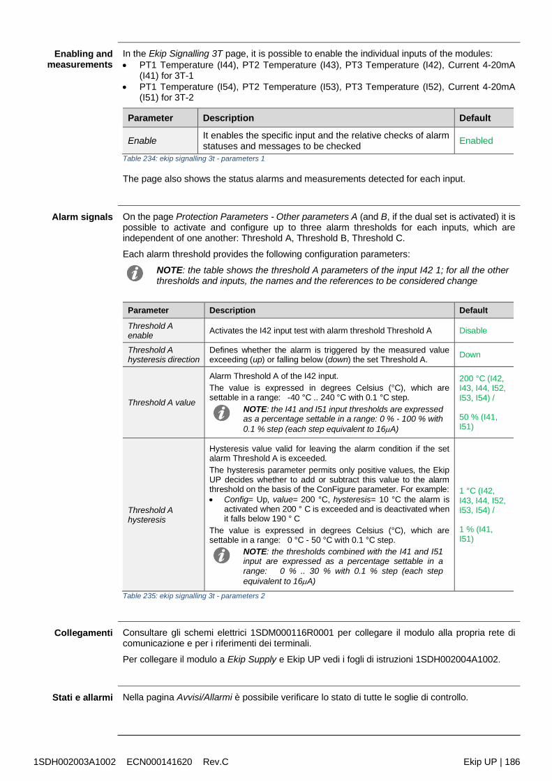
1SDH002003A1002 ECN000141620 Rev.C Ekip UP | 186
Enabling andmeasurements
In the Ekip Signalling 3T page, it is possible to enable the individual inputs of the modules: PT1 Temperature (I44), PT2 Temperature (I43), PT3 Temperature (I42), Current 4-20mA
(I41) for 3T-1 PT1 Temperature (I54), PT2 Temperature (I53), PT3 Temperature (I52), Current 4-20mA
(I51) for 3T-2
Parameter Description Default
Enable It enables the specific input and the relative checks of alarmstatuses and messages to be checked Enabled
Table 234: ekip signalling 3t - parameters 1
The page also shows the status alarms and measurements detected for each input.
Alarm signals On the page Protection Parameters - Other parameters A (and B, if the dual set is activated) it ispossible to activate and configure up to three alarm thresholds for each inputs, which areindependent of one another: Threshold A, Threshold B, Threshold C.
Each alarm threshold provides the following configuration parameters:
NOTE: the table shows the threshold A parameters of the input I42 1; for all the otherthresholds and inputs, the names and the references to be considered change
Parameter Description Default
Threshold Aenable Activates the I42 input test with alarm threshold Threshold A Disable
Threshold Ahysteresis direction
Defines whether the alarm is triggered by the measured valueexceeding (up) or falling below (down) the set Threshold A. Down
Threshold A value
Alarm Threshold A of the I42 input.The value is expressed in degrees Celsius (°C), which aresettable in a range: -40 °C .. 240 °C with 0.1 °C step.
NOTE: the I41 and I51 input thresholds are expressedas a percentage settable in a range: 0 % - 100 % with0.1 % step (each step equivalent to 16A)
200 °C (I42,I43, I44, I52,I53, I54) /
50 % (I41,I51)
Threshold Ahysteresis
Hysteresis value valid for leaving the alarm condition if the setalarm Threshold A is exceeded.The hysteresis parameter permits only positive values, the EkipUP decides whether to add or subtract this value to the alarmthreshold on the basis of the ConFigure parameter. For example: Config= Up, value= 200 °C, hysteresis= 10 °C the alarm is
activated when 200 ° C is exceeded and is deactivated whenit falls below 190 ° C
The value is expressed in degrees Celsius (°C), which aresettable in a range: 0 °C - 50 °C with 0.1 °C step.
NOTE: the thresholds combined with the I41 and I51input are expressed as a percentage settable in arange: 0 % .. 30 % with 0.1 % step (each stepequivalent to 16A)
1 °C (I42,I43, I44, I52,I53, I54) /
1 % (I41,I51)
Table 235: ekip signalling 3t - parameters 2
Collegamenti Consultare gli schemi elettrici 1SDM000116R0001 per collegare il modulo alla propria rete dicomunicazione e per i riferimenti dei terminali.
Per collegare il modulo a Ekip Supply e Ekip UP vedi i fogli di istruzioni 1SDH002004A1002.
Stati e allarmi Nella pagina Avvisi/Allarmi è possibile verificare lo stato di tutte le soglie di controllo.
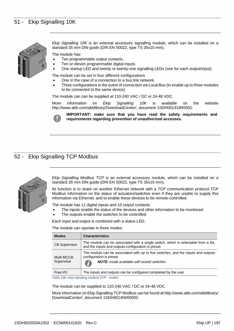
1SDH002003A1002 ECN000141620 Rev.C Ekip UP | 187
51 - Ekip Signalling 10K
Ekip Signalling 10K is an external accessory signalling module, which can be installed on astandard 35 mm DIN guide (DIN EN 50022, type TS 35x15 mm).
The module has: Ten programmable output contacts. Ten or eleven programmable digital inputs. One startup LED and twenty or twenty-one signalling LEDs (one for each output/input).
The module can be set in four different configurations One in the case of a connection to a bus link network. Three configurations in the event of connection via Local Bus (to enable up to three modules
to be connected to the same device)
The module can can be supplied at 110-240 VAC / DC or 24-48 VDC.
More information on Ekip Signalling 10K is available on the websitehttp://www.abb.com/abblibrary/DownloadCenter/, document 1SDH001318R0002.
IMPORTANT: make sure that you have read the safety requirements andrequirements regarding prevention of unauthorized accesses.
52 - Ekip Signalling TCP Modbus
Ekip Signalling Modbus TCP is an external accessory module, which can be installed on astandard 35 mm DIN guide (DIN EN 50022, type TS 35x15 mm).
Its function is to share on another Ethernet network with a TCP communication protocol TCPModbus information on the status of actuators/switches even if they are unable to supply thisinformation via Ethernet, and to enable these devices to be remote-controlled.
The module has 11 digital inputs and 10 output contacts: The inputs enable the status of the devices and other information to be monitored. The outputs enable the switches to be controlled.
Each input and output is combined with a status LED.
The module can operate in three modes:
Modes Characteristics
CB Supervisor The module can be associated with a single switch, which is selectable from a list,and the inputs and outputs configuration is preset
Multi MCCBSupervisor
The module can be associated with up to five switches, and the inputs and outputsconfiguration is preset
NOTE: mode available with boxed switches
Free I/O The inputs and outputs can be configured completed by the userTable 236: ekip signaling modbud TCP - modes
The module can be supplied to 110-240 VAC / DC or 24-48 VDC.More information on Ekip Signalling TCP Modbus can be found at http://www.abb.com/abblibrary/DownloadCenter/, document 1SDH001456R0002.
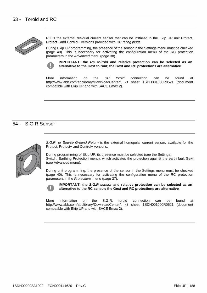
1SDH002003A1002 ECN000141620 Rev.C Ekip UP | 188
53 - Toroid and RC
RC is the external residual current sensor that can be installed in the Ekip UP unit Protect,Protect+ and Control+ versions provided with RC rating plugs.
During Ekip UP programming, the presence of the sensor in the Settings menu must be checked(page 40). This is necessary for activating the configuration menu of the RC protectionparameters in the Advanced menu (page 38).
IMPORTANT: the RC toiroid and relative protection can be selected as analternative to the Gext toiroid; the Gext and RC protections are alternative
More information on the RC toroid connection can be found athttp://www.abb.com/abblibrary/DownloadCenter/, kit sheet 1SDH001000R0521 (documentcompatible with Ekip UP and with SACE Emax 2).
54 - S.G.R Sensor
S.G.R. or Source Ground Return is the external homopolar current sensor, available for theProtect, Protect+ and Control+ versions.
During programming of Ekip UP, its presence must be selected (see the Settings,Switch, Earthing Protection menu), which activates the protection against the earth fault Gext(see Advanced menu).
During unit programming, the presence of the sensor in the Settings menu must be checked(page 40). This is necessary for activating the configuration menu of the RC protectionparameters in the Protections menu (page 37).
IMPORTANT: the S.G.R sensor and relative protection can be selected as analternative to the RC sensor; the Gext and RC protections are alternative
More information on the S.G.R. toroid connection can be found athttp://www.abb.com/abblibrary/DownloadCenter/, kit sheet 1SDH001000R0521 (documentcompatible with Ekip UP and with SACE Emax 2).
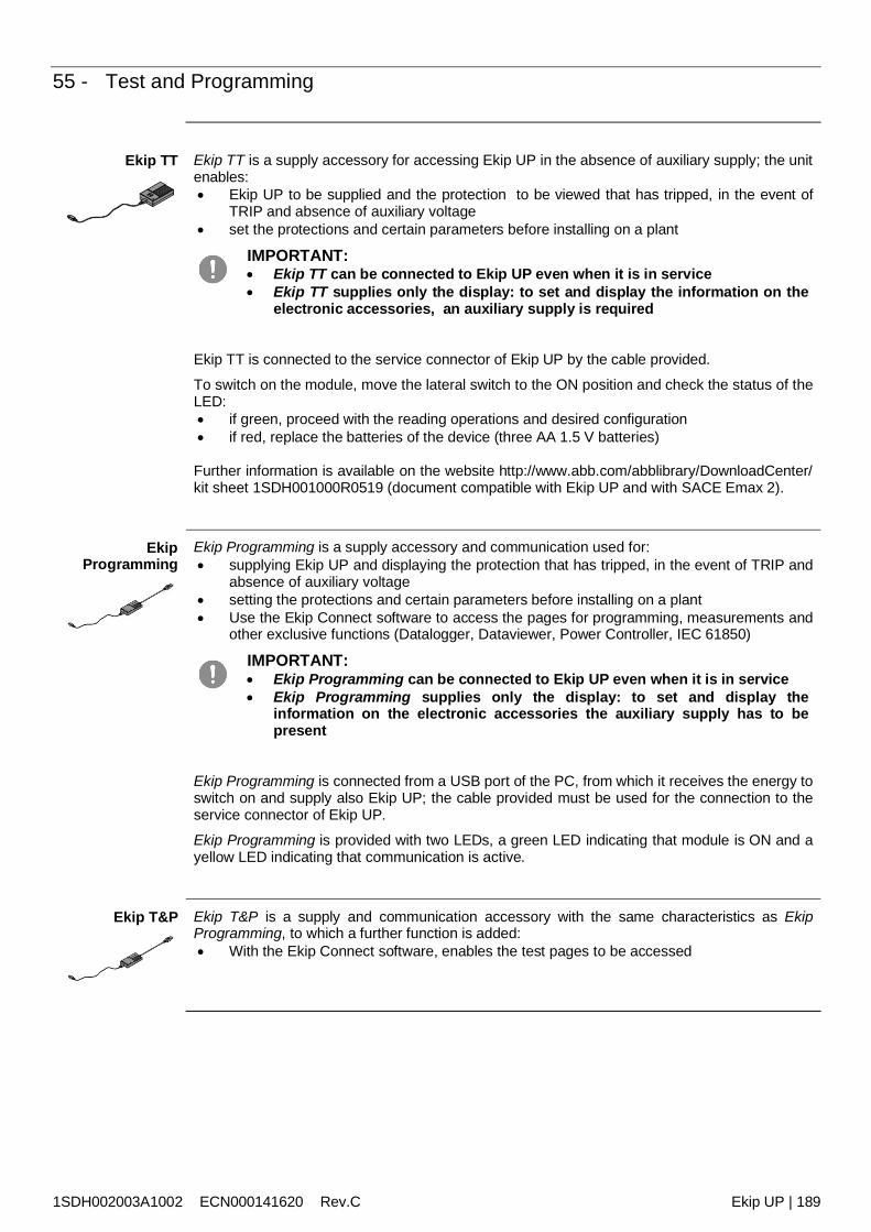
1SDH002003A1002 ECN000141620 Rev.C Ekip UP | 189
55 - Test and Programming
Ekip TT Ekip TT is a supply accessory for accessing Ekip UP in the absence of auxiliary supply; the unitenables: Ekip UP to be supplied and the protection to be viewed that has tripped, in the event of
TRIP and absence of auxiliary voltage set the protections and certain parameters before installing on a plant
IMPORTANT: Ekip TT can be connected to Ekip UP even when it is in service Ekip TT supplies only the display: to set and display the information on the
electronic accessories, an auxiliary supply is required
Ekip TT is connected to the service connector of Ekip UP by the cable provided.
To switch on the module, move the lateral switch to the ON position and check the status of theLED: if green, proceed with the reading operations and desired configuration if red, replace the batteries of the device (three AA 1.5 V batteries)
Further information is available on the website http://www.abb.com/abblibrary/DownloadCenter/kit sheet 1SDH001000R0519 (document compatible with Ekip UP and with SACE Emax 2).
EkipProgramming
Ekip Programming is a supply accessory and communication used for: supplying Ekip UP and displaying the protection that has tripped, in the event of TRIP and
absence of auxiliary voltage setting the protections and certain parameters before installing on a plant Use the Ekip Connect software to access the pages for programming, measurements and
other exclusive functions (Datalogger, Dataviewer, Power Controller, IEC 61850)
IMPORTANT: Ekip Programming can be connected to Ekip UP even when it is in service Ekip Programming supplies only the display: to set and display the
information on the electronic accessories the auxiliary supply has to bepresent
Ekip Programming is connected from a USB port of the PC, from which it receives the energy toswitch on and supply also Ekip UP; the cable provided must be used for the connection to theservice connector of Ekip UP.
Ekip Programming is provided with two LEDs, a green LED indicating that module is ON and ayellow LED indicating that communication is active.
Ekip T&P Ekip T&P is a supply and communication accessory with the same characteristics as EkipProgramming, to which a further function is added: With the Ekip Connect software, enables the test pages to be accessed
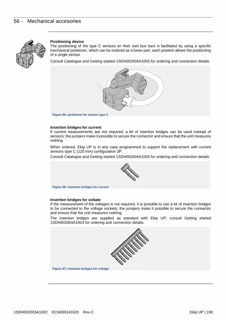
1SDH002003A1002 ECN000141620 Rev.C Ekip UP | 190
56 - Mechanical accesories
Positioning deviceThe positioning of the type C sensors on their own bus bars is facilitated by using a specificmechanical positioner, which can be ordered as a loose part; each position allows the positioningof a single sensor.
Consult Catalogue and Getting started 1SDH002004A1003 for ordering and connection details.
Figure 65: positioner for sensor type C
Insertion bridges for currentIf current measurements are not required, a kit of insertion bridges can be used instead ofsensors; the jumpers make it possible to secure the connector and ensure that the unit measuresnothing.
When ordered, Ekip UP is in any case programmed to support the replacement with currentsensors type C (120 mm) configuration 3P.Consult Catalogue and Getting started 1SDH002004A1003 for ordering and connection details.
Figure 66: insertion bridges for current
Insertion bridges for voltateIf the measurement of the voltages is not required, it is possible to use a kit of insertion bridgesto be connected to the voltage sockets; the jumpers make it possible to secure the connectorand ensure that the unit measures nothing.The insertion bridges are supplied as standard with Ekip UP; consult Getting started1SDH002004A1003 for ordering and connection details.
Figure 67: insertion bridges for voltage

1SDH002003A1002 ECN000141620 Rev.C Ekip UP | 191
Reviews
Review ECN Description
A ECN000071509 First version
B ECN000089543 Rating plugs inserted, current sensors, 3T signaling, mechanical accessories, additionalfunctions and relative menu areas; updated regulations, graphics, documentation
C ECN000141620 Table updated on: RQ protection, Voltage protections and power protections

© Copyright 2018-2020 ABB. All right reserved
1SD
H00
2003
A100
2
ECN
0001
4162
0
Rev
C