Embed Size (px)
Citation preview
All In the Family: Creating Parametric Components In Autodesk® Revit® Matt Dillon – D|C|CADD
AB4013 The key to mastering Autodesk® Revit® Architecture, Revit MEP, or Revit Structure is the ability to create intelligent, parametric families for your content libraries. It's not as easy as simply building a 3D model. This class will show you how to use the modeling tools in the Revit Family Editor, as well as the process of creating intelligent parameters to properly control their dimensions, behavior, and visibility. Additionally, you will learn how to make sure that your families "play nice" with other elements in your model.
LearningObjectivesAt the end of this class, you will be able to:
Understand Family Templates
Work with Parameters and Constraints
Understand Modeling Tools
Work with Nested Families
AbouttheSpeaker Having been a registered architect with over 20 years of experience in Autodesk® architectural applications, Matt has worked with AutoCAD® Architecture since its initial release and Revit® Architecture since its purchase by Autodesk. Matt is an Autodesk Certified Instructor at an Autodesk Authorized Training Center. In addition to assisting customers in implementing Autodesk Revit platform products, he has also consulted with Autodesk development staff in product design and usability for AutoCAD Architecture. He co-authored Architectural Desktop 2007—An Advanced Implementation Guide (Second Edition). In 2010, Matt was one of the recipients of Autodesk's "Distinguished Speaker Award" and has consistently been a highly-rated instructor at Autodesk University since he began presenting in 2000.
All In the Family: Creating Parametric Components In Autodesk® Revit®
2
ConceptualOverviewFamilies are the heart of the internal data structure of Autodesk Revit. Every object, whether it is a geometric component, an annotation component, a View or any other component in Revit, is part of a Family. Families come in three “flavors”:
System Families are managed by Revit, and cannot be created or deleted. They typically are not shared between Projects. Views, dimensions, text, etc. all belong to System families, as do geometric objects such as ducts and pipes (anything that would be assembled on the job site).
Component Families (the focus of this class) can be created and customized, and can be stored in an external library, to be loaded into your Revit project on an “as needed” basis. Examples of Component Families are equipment, fixtures, devices and fittings, as well as custom annotation tags and callouts. When considering geometry, Component Families are objects that might be ordered out of a catalog and installed or placed on the job site.
In-Place Familes represent “one-off” items; custom geometry that is not meant to be re-used or shared between projects.
One of the strengths of component families is that they can be controlled by parameters, which allow for a great deal of flexibility. For example a table family can be created to have several sizes, all based on parameters that can be set by the user, allowing for a single family definition to accommodate several different kinds of tables. Parameters can control more than just sizes and distances, however. They can control materials, visibility states and non-graphical information (such as catalog number, voltage, cost, etc.).
Revit Component Families are a unique file type, with an extension of RFA. To create a family, you begin a new file by selecting File->New->Family from the Revit application menu. After selecting the appropriate family template, you’ll be placed in the Revit Family Editor. The Family Editor looks just like the normal Revit interface, except that it has a different set of ribbons that include all of the tools that you will need to create your family.
ComponentFamilyCreationProcessWhile each family will vary in complexity and features, the basic process to create a component family will be the same:
1. Select the family template. This is the most important part of creating a family. The template will determine not only the category (and therefore the available default parameters) of the family, but also how it will behave and interact with other Revit components.
2. Plan the major parameters. Parameters are what control any variable values (sizes, materials, informational elements, etc. of the family). In addition to deciding what the parameters need to be, you will also need to consider whether they will need to be used in schedules or tags, and whether they will be type or instance parameters.
3. Create and constrain model geometry. This will entail laying out critical reference planes and constraining geometry with parameters. We will look at this more closely in the “Modeling Tools and Methods” and “Parameters and Constraints” sections of this paper.
4. Assign Object Subcategories if necessary. This will allow you to have independent control of the component in visibility graphics overrides, object styles and material assignments. If necessary, you can create new subcategories within your Revit Family.
All In the Family: Creating Parametric Components In Autodesk® Revit®
3
5. Set visibility rules. Some geometry may not be appropriate in all views or detail levels. Using the visibility tools in Revit families, you can control when each component will be visible.
6. Create Family Types. Many component families contain multiple type definitions. An example of family types is found with Door families. The door size is defined by type definitions. Family types make it easy to change multiple parameters simply by selecting an overall type definition.
UnderstandingFamilyTemplatesAs stated previously, the most important step in creating a component family is to choose the family template. The template will determine not only which object category the component will be a part of, but also how the family will act when it comes in contact with other components. In some cases you will also need to determine whether a family will be hosted or not, and if so, what type of object will serve as the host. For example, if you are creating a toilet fixture, you can choose from the non-hosted Plumbing Fixture.rft template or the hosted Plumbing Fixture wall based.rft template. If your fixture is a wall-mounted toilet, then you would choose the wall-based template, meaning that the family can only be placed on a wall. Another example of hosted families are light fixtures. A ceiling-hosted light fixture can only be inserted on a ceiling object. Hosted components will be attached to their hosts, “following” them wherever the host goes.
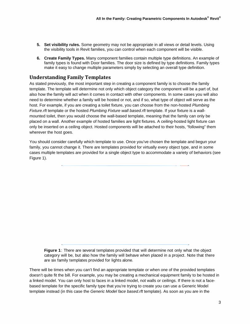
You should consider carefully which template to use. Once you’ve chosen the template and begun your family, you cannot change it. There are templates provided for virtually every object type, and in some cases multiple templates are provided for a single object type to accommodate a variety of behaviors (see Figure 1).
Figure 1: There are several templates provided that will determine not only what the object category will be, but also how the family will behave when placed in a project. Note that there are six family templates provided for lights alone.
There will be times when you can’t find an appropriate template or when one of the provided templates doesn’t quite fit the bill. For example, you may be creating a mechanical equipment family to be hosted in a linked model. You can only host to faces in a linked model, not walls or ceilings. If there is not a face-based template for the specific family type that you’re trying to create you can use a Generic Model template instead (in this case the Generic Model face based.rft template). As soon as you are in the
All In the Family: Creating Parametric Components In Autodesk® Revit®
4
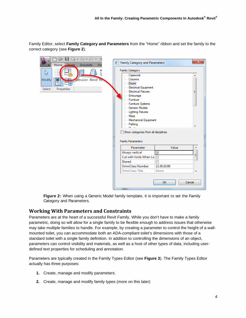
Family Editor, select Family Category and Parameters from the “Home” ribbon and set the family to the correct category (see Figure 2).
Figure 2: When using a Generic Model family template, it is important to set the Family Category and Parameters.
WorkingWithParametersandConstraintsParameters are at the heart of a successful Revit Family. While you don’t have to make a family parametric, doing so will allow for a single family to be flexible enough to address issues that otherwise may take multiple families to handle. For example, by creating a parameter to control the height of a wall-mounted toilet, you can accommodate both an ADA-compliant toilet’s dimensions with those of a standard toilet with a single family definition. In addition to controlling the dimensions of an object, parameters can control visibility and materials, as well as a host of other types of data, including user-defined text properties for scheduling and annotation.
Parameters are typically created in the Family Types Editor (see Figure 3). The Family Types Editor actually has three purposes:
1. Create, manage and modify parameters.
2. Create, manage and modify family types (more on this later)
All In the Family: Creating Parametric Components In Autodesk® Revit®
5
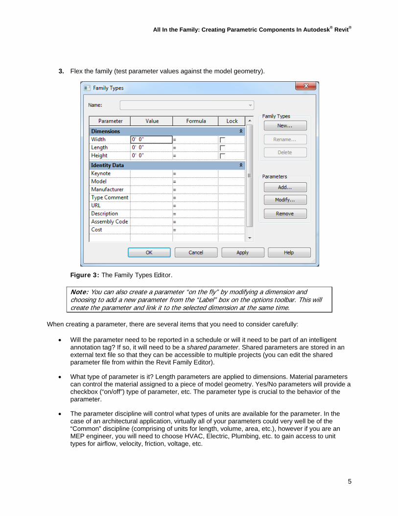
3. Flex the family (test parameter values against the model geometry).
Figure 3: The Family Types Editor.
Note: You can also create a parameter “on the fly” by modifying a dimension and choosing to add a new parameter from the “Label” box on the options toolbar. This will create the parameter and link it to the selected dimension at the same time.
When creating a parameter, there are several items that you need to consider carefully:
Will the parameter need to be reported in a schedule or will it need to be part of an intelligent annotation tag? If so, it will need to be a shared parameter. Shared parameters are stored in an external text file so that they can be accessible to multiple projects (you can edit the shared parameter file from within the Revit Family Editor).
What type of parameter is it? Length parameters are applied to dimensions. Material parameters can control the material assigned to a piece of model geometry. Yes/No parameters will provide a checkbox (“on/off”) type of parameter, etc. The parameter type is crucial to the behavior of the parameter.
The parameter discipline will control what types of units are available for the parameter. In the case of an architectural application, virtually all of your parameters could very well be of the “Common” discipline (comprising of units for length, volume, area, etc.), however if you are an MEP engineer, you will need to choose HVAC, Electric, Plumbing, etc. to gain access to unit types for airflow, velocity, friction, voltage, etc.

All In the Family: Creating Parametric Components In Autodesk® Revit®
6
Will the parameter be type-based or instance-based? In other words, will the parameter actually define a new type within the family or will it be able to be edited on an element-by-element basis?
Note: Revit 2011 introduced a new kind of parameter. Instance-based parameters can also be reporting parameters. While outside the scope of this introductory tutorial, this type of parameter provides powerful new capabilities. You should research and experiment with these once you have become more comfortable with the basics of creating custom component families.
Figure 4: Consider carefully the properties of the parameters that you create.
GuidelinesforGeometricParametersandConstraintsWhen using parameters and constraints to control physical geometry, there are some simple but definite do’s and dont’s:
When applying a dimension parameter always dimension to reference planes. Never, under any circumstances, should you dimension to an actual piece of geometry or a sketch line if you are going to use a parameter to control the dimension. Doing so will result in a “Constraints not satisfied” error message. After assigning parameter dimensions to your reference planes, you can constrain (lock) the sketch geometry to the reference planes. The dimension parameter will actually control the position of the reference planes, which will in turn control the position of the model geometry.
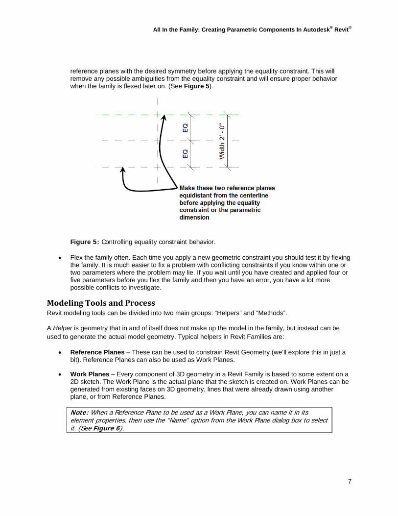
When using an equality constraint to make geometry symmetrical about a center line while allowing it to grow or shrink about the centerline with an overall parametric constraint, create the
All In the Family: Creating Parametric Components In Autodesk® Revit®
7
reference planes with the desired symmetry before applying the equality constraint. This will remove any possible ambiguities from the equality constraint and will ensure proper behavior when the family is flexed later on. (See Figure 5).
Figure 5: Controlling equality constraint behavior.
Flex the family often. Each time you apply a new geometric constraint you should test it by flexing the family. It is much easier to fix a problem with conflicting constraints if you know within one or two parameters where the problem may lie. If you wait until you have created and applied four or five parameters before you flex the family and then you have an error, you have a lot more possible conflicts to investigate.
ModelingToolsandProcessRevit modeling tools can be divided into two main groups: “Helpers” and “Methods”.
A Helper is geometry that in and of itself does not make up the model in the family, but instead can be used to generate the actual model geometry. Typical helpers in Revit Families are:
Reference Planes – These can be used to constrain Revit Geometry (we’ll explore this in just a bit). Reference Planes can also be used as Work Planes.
Work Planes – Every component of 3D geometry in a Revit Family is based to some extent on a 2D sketch. The Work Plane is the actual plane that the sketch is created on. Work Planes can be generated from existing faces on 3D geometry, lines that were already drawn using another plane, or from Reference Planes.
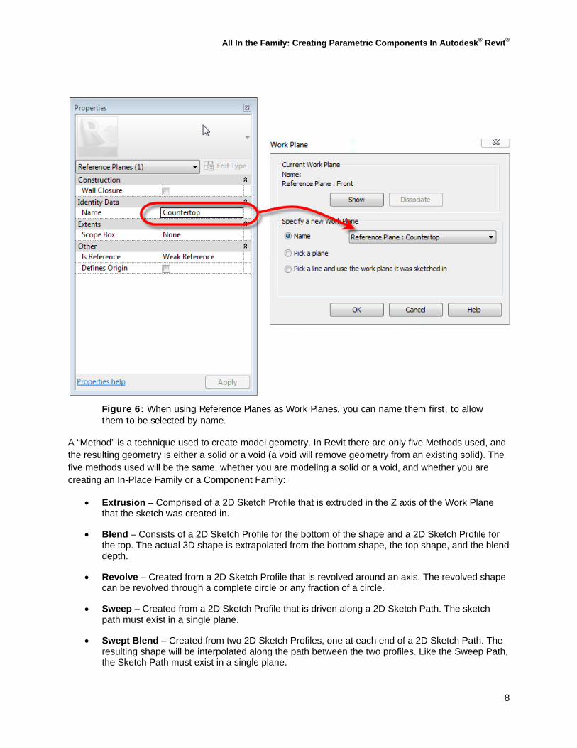
Note: When a Reference Plane to be used as a Work Plane, you can name it in its element properties, then use the “Name” option from the Work Plane dialog box to select it. (See Figure 6).
All In the Family: Creating Parametric Components In Autodesk® Revit®
8
Figure 6: When using Reference Planes as Work Planes, you can name them first, to allow them to be selected by name.
A “Method” is a technique used to create model geometry. In Revit there are only five Methods used, and the resulting geometry is either a solid or a void (a void will remove geometry from an existing solid). The five methods used will be the same, whether you are modeling a solid or a void, and whether you are creating an In-Place Family or a Component Family:
Extrusion – Comprised of a 2D Sketch Profile that is extruded in the Z axis of the Work Plane that the sketch was created in.
Blend – Consists of a 2D Sketch Profile for the bottom of the shape and a 2D Sketch Profile for the top. The actual 3D shape is extrapolated from the bottom shape, the top shape, and the blend depth.
Revolve – Created from a 2D Sketch Profile that is revolved around an axis. The revolved shape can be revolved through a complete circle or any fraction of a circle.
Sweep – Created from a 2D Sketch Profile that is driven along a 2D Sketch Path. The sketch path must exist in a single plane.
Swept Blend – Created from two 2D Sketch Profiles, one at each end of a 2D Sketch Path. The resulting shape will be interpolated along the path between the two profiles. Like the Sweep Path, the Sketch Path must exist in a single plane.
All In the Family: Creating Parametric Components In Autodesk® Revit®
9
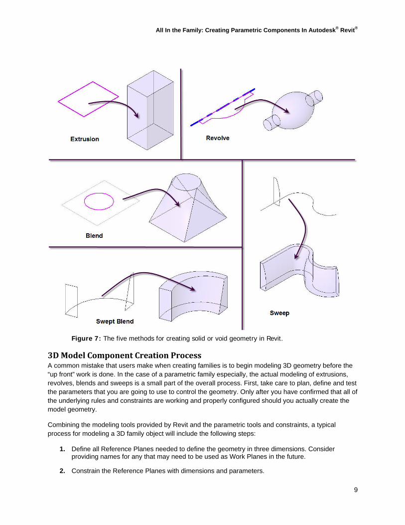
Figure 7: The five methods for creating solid or void geometry in Revit.
3DModelComponentCreationProcessA common mistake that users make when creating families is to begin modeling 3D geometry before the “up front” work is done. In the case of a parametric family especially, the actual modeling of extrusions, revolves, blends and sweeps is a small part of the overall process. First, take care to plan, define and test the parameters that you are going to use to control the geometry. Only after you have confirmed that all of the underlying rules and constraints are working and properly configured should you actually create the model geometry.
Combining the modeling tools provided by Revit and the parametric tools and constraints, a typical process for modeling a 3D family object will include the following steps:
1. Define all Reference Planes needed to define the geometry in three dimensions. Consider providing names for any that may need to be used as Work Planes in the future.
2. Constrain the Reference Planes with dimensions and parameters.

All In the Family: Creating Parametric Components In Autodesk® Revit®
10
3. Flex the Family to test the behavior of the Reference Planes against the parameters and constraints.
4. Begin the creation of the Solid or Void geometry using either an extrusion, revolve, blend, sweep or swept blend.
5. Check and set the Work Plane for the sketch geometry. It is important to do this first, if for no other reason than to ensure that you’re drawing the sketch where you think you are (see Figure 8). Note that you can also set the current Work Plane at any time by selecting the Work Plane tool on the “Home” ribbon, and you can display the current Work Plane using the Work Plane Display toggle on the ribbon or using the new Work Plane Viewer as well (see Figure 8).
Figure 8: Setting the current Work Plane and toggling display.
6. Create the sketch geometry. Lock the geometry to your reference planes.
7. Set the object’s properties. Specific properties that you are interested in include the depth (in the case of an extrusion or blend), the material of the object, visibility and sub-category (if necessary). You can also set the properties after the object has been created and you have exited sketch mode. It is also important to note that you can link properties to parameters. For example, if you have created a Yes/No parameter, that parameter can be used to control the Visibility property of the object (see Figure 9).
Figure 9: Object properties in families can be linked to parameters of the appropriate type.

All In the Family: Creating Parametric Components In Autodesk® Revit®
11
8. Finish the Sketch, which will complete the object and apply the 3D properties to the 2D Sketch geometry.
9. Flex the Family, testing both the dimensional constraints and parameters again as well as any parameters that you linked to object properties. If there are any errors, you can either edit the sketch or modify any parameter-based properties to resolve the issue before going on to the next geometric component.
WorkingwithNestedFamiliesThere will frequently be cases where a component used in a family will also be needed in other families. For example, if you wanted to show doorknobs in a 3D “Fine Detail” view of your custom door families, that same door knob may show up in several different family files. Rather than model it in each and every door family, you can simply model it once as its own family, then add it as a component in all of the door families in which it is needed.
Note: In the example above, consider how you would start the doorknob family. You would not use the Door.rft template file, because then the doorknob would want to be hosted by a wall. Instead, you would use the Generic Model face based.rft family template, then use the Family Category and Parameters tool to establish it as a part of the Door category. This way, it will be the correct category but will be hosted by the face of the door panel instead of being hosted by a wall.
When you create a family that will be “nested” in another family, you need to consider two things:
Does it need to be scheduled separately from the host family or as an integral part of it? If separate, then it needs to be specified as “Shared” in the Family Category and Parameters box of the nested family (see Figure 10). If it does not need to be scheduled separately, leave this box blank.
Figure 10: Changing the category and scheduling properties of a nested generic family.

All In the Family: Creating Parametric Components In Autodesk® Revit®
12
Parameters, when created in a family become properties when that family is placed in a project (either type or instance-based, depending upon how you created the parameter). The same thing happens when you insert a family into another family. In the host family, what were parameters are now properties. When a family is inserted into a project, properties that were accessible in the family editor are no longer accessible in the project. So, if you insert a family with parameters into another family, then you insert that host family into a project, the parameters of the nested family are not available for editing. You can resolve this by creating parameters in the host family and linking those parameters to the properties you need to be editable in the “downstream” project (see Figure 11).
Figure 11: Linking parameters in a nested family. 1) Click the button next to the property of the component in the family that you want to be able to control when it is imported into another project or family. 2) Assign the parameter. 3) The property is now being controlled by the parameter. 4) When imported into another family or a project, the parameter becomes a property of the nested family.
SummaryHopefully this short class was of value to you, whether you are a “family neophyte” or just wanted to fill in a few knowledge gaps. If you are just starting out with families, remember to start small and work your way up in complexity. Families do not have to be parametric; you can build non-parametric families at first until you are comfortable with the modeling techniques, then gradually work up to more complex families with parameters to control virtually all aspects of an object’s behavior.


![Joomla overrides [NL]](https://img.pdfslide.us/doc/110x75/55b9d179bb61eb29258b459a/joomla-overrides-nl.jpg)