Embed Size (px)
Citation preview
ConnectorsMil-C-26482 Series 1 Style
AB05/6

TT Electronics’ brand AB Connectors specialises in the design, test and manufacture of high performance electronic connectors and interconnect solutions, supplying a range of global customers in aerospace, defence, rail and industrial markets.
Our broad product portfolio which includes miniature connectors, high power connectors, soldier systems, harness assemblies and box systems typically serve within key applications such as signalling, communication and power distribution.
Operating from the principle site in Abercynon, South Wales, our research and development teams have an excellent track record for developing innovative industry solutions and our engineers have extensive experience in designing a range of product configurations to meet customer specific requirements for the most demanding environments.
From plant layout to production line set-up and quick changeover processes, we offer the ideal service, with a flexible manufacturing environment and accredited facilities.
Quality systems and approvals include ISO9001 along with various product and market sector approvals including the military Mil-std 790 and mass transit IRIS certifications and environmental approval to ISO14001. As a result of these qualifications AB Connectors has been awarded several major customer approvals and accreditations.
AB Connectors total commitment to providing customers with high levels of service, cost effectiveness, quality and innovative solutions in interconnection products make it the ideal first choice supply partner.
Company ProfileTT Electronics’ brand AB Connectors specialises in the design, test and manufacture of high performance electronic connectors and interconnect solutions, supplying a range of global customers in aerospace, defence, rail and industrial markets.
Our broad product portfolio which includes miniature connectors, high power connectors, soldier systems, harness assemblies and box systems typically serve within key applications such as signalling, communication and power distribution.
Operating from the principle site in Abercynon, South Wales, our research and development teams have an excellent track record for developing innovative industry solutions and our engineers have extensive experience in designing a range of product configurations to meet customer specific requirements for the most demanding environments.
From plant layout to production line set-up and quick changeover processes, we offer the ideal service, with a flexible manufacturing environment and accredited facilities.
Quality systems and approvals include ISO9001 along with various product and market sector approvals including the military Mil-std 790 and mass transit IRIS certifications and environmental approval to ISO14001. As a result of these qualifications AB Connectors has been awarded several major customer approvals and accreditations.
AB Connectors total commitment to providing customers with high levels of service, cost effectiveness, quality and innovative solutions in interconnection products make it the ideal first choice supply partner.
TT Electronics’ brand AB Connectors specialises in the design, test and manufacture of high performance electronic connectors and interconnect solutions, supplying a range of global customers in aerospace, defence, rail and industrial markets.
Our broad product portfolio which includes miniature connectors, high power connectors, soldier systems, harness assemblies and box systems typically serve within key applications such as signalling, communication and power distribution.
Operating from the principle site in Abercynon, South Wales, our research and development teams have an excellent track record for developing innovative industry solutions and our engineers have extensive experience in designing a range of product configurations to meet customer specific requirements for the most demanding environments.
From plant layout to production line set-up and quick changeover processes, we offer the ideal service, with a flexible manufacturing environment and accredited facilities.
Quality systems and approvals include ISO9001 along with various product and market sector approvals including the military Mil-std 790 and mass transit IRIS certifications and environmental approval to ISO14001. As a result of these qualifications AB Connectors has been awarded several major customer approvals and accreditations.
AB Connectors total commitment to providing customers with high levels of service, cost effectiveness, quality and innovative solutions in interconnection products make it the ideal first choice supply partner.

2 - 36 AB05 - Miniature Bayonet Coupling Connectors
37 - 42 AB05 - 10-76 Miniature Bayonet Coupling Connectors
43 - 61 AB06 - Audio Miniature Bayonet Lock Connectors
Contents
2
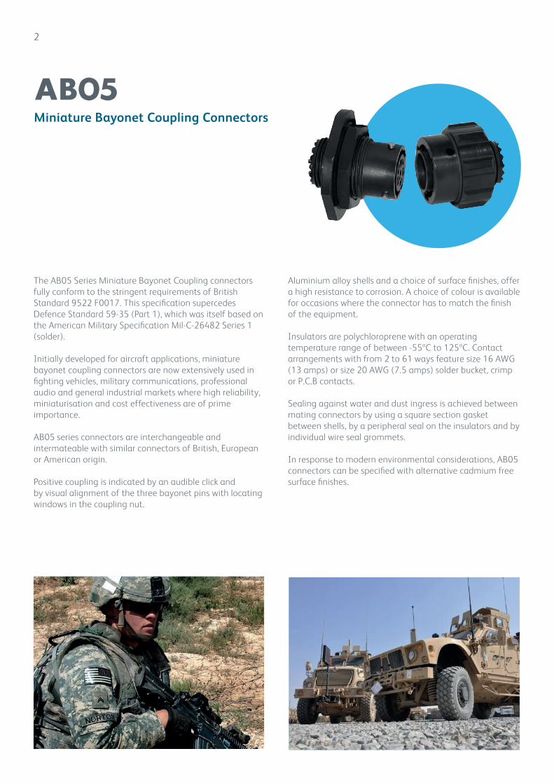
The AB05 Series Miniature Bayonet Coupling connectors fully conform to the stringent requirements of British Standard 9522 F0017. This specification supercedes Defence Standard 59-35 (Part 1), which was itself based on the American Military Specification Mil-C-26482 Series 1(solder).
Initially developed for aircraft applications, miniature bayonet coupling connectors are now extensively used in fighting vehicles, military communications, professional audio and general industrial markets where high reliability, miniaturisation and cost effectiveness are of prime importance.
AB05 series connectors are interchangeable and intermateable with similar connectors of British, European or American origin.
Positive coupling is indicated by an audible click andby visual alignment of the three bayonet pins with locating windows in the coupling nut.
Aluminium alloy shells and a choice of surface finishes, offer a high resistance to corrosion. A choice of colour is available for occasions where the connector has to match the finish of the equipment.
Insulators are polychloroprene with an operating temperature range of between -55ºC to 125ºC. Contact arrangements with from 2 to 61 ways feature size 16 AWG (13 amps) or size 20 AWG (7.5 amps) solder bucket, crimp or P.C.B contacts.
Sealing against water and dust ingress is achieved between mating connectors by using a square section gasket between shells, by a peripheral seal on the insulators and by individual wire seal grommets.
In response to modern environmental considerations, AB05 connectors can be specified with alternative cadmium free surface finishes.
Miniature Bayonet Coupling Connectors
AB05
Miniature Bayonet Coupling Connectors
AB05
3
Contents Page
AB05 Miniature Bayonet Coupling Connectors 2-36
Technical Information 4
Part No. Explanation 5
Arrangement Specifications 6
Contact Arrangements 7-8
Receptacles
AB05 1000: cable connecting receptacle 9
AB05 2000: receptacle, square flange with accessory thread 10
AB05 2100: receptacle, square flange w/o accessory thread 11
AB05 3100: receptacle, jam nut w/o accessory thread 12
AB05 3200: receptacle, jam nut with accessory thread 13
Plugs
AB05 6000: plug, knurled coupling nut 14
AB05 6100: plug, knurled coupling nut with grounding fingers 15
AB05 6200: plug, coarse ribbed coupling nut 16
AB05 6300: plug, coarse ribbed coupling nut with grounding fingers 17
Accessories
Accessories Part No. Explanation 18
AB05 0027: strain relief clamp 19
AB05 0029: straight outlet for internally screened cables 20
AB05 0030: straight outlet for externally screened cables 21
AB05 0040: grommet nut 22
AB05 0050: general duty adaptor 23
AB05 0055: sealing gland 24
AB05 0062: sealing gland with integral cable clamp 25
AB05 0065 / AB05 0066: cover for square flange receptacle 26
AB05 0070: cover for plug 27
AB05 0075: screen and heat shrink adaptor 28
AB05 002*: screening heat shrink adaptor, sealing type 29
AB05 003*: screening heat shrink adaptor 90º outlet, sealing type 30
AB05 size240-0-00-AC: filler plug 31
AB05 size382-0-00-AC: panel gasket 31
AB05 size430-0-00-AC: cable grommet 32
AB05 2300: stowage receptacles 32
AB05 Printed Circuit Board Contacts 33
AB05 Crimp Contacts and Assembly Tools 34
Assembly Procedures for Cables used on AB05 0029 and 0030 Straight Outlets 35-36
AB05 10-76 Miniature Bayonet Coupling Connectors 37-42
AB06 Audio Miniature Bayonet Lock Connectors Range 43-61
Safety Information 62

4
Technical information
AB05
Mechanical Features
Shell size: 8 to 24, measured in sixteenths of an inch
Coupling: Three pin bayonet
Contact Termination: Solder bucket, crimp (rubber retention), pin tails for P.C.B. applications and flexible printing wiring
Sealing: Barrier, or barrier and panel seal.
Dynamic peripheral seal between mating shells.
Materials
Shell: Aluminium alloy
Insulator: Polychloroprene
Grommet: Polychloroprene
Contacts: Brass
Accessories Hardware: Aluminium alloy
Plating Finishes
Shell: Conductive, olive drab over cadmium plate (alternatives available on request)
Contacts: Gold over nickel
Accessory Hardware: Conductive, olive drab over cadmium plate (alternatives available on request)
Technical Data
Temperature Range: -55ºC to +125ºC
Voltage at Sea Level: a) Working Voltage - d.c. or a.c. peak:
Size 20 Contacts: 700V (Voltage rating 1)
Size 16 Contacts: 1200V (Voltage rating 2)
b) Proof Voltage - d.c. or a.c. peak:
Size 20 Contacts: 2100V (Voltage rating 1)
Size 16 Contacts: 3000V (Voltage rating 2)
The establishment of electrical safety factors when the connector is used at other than the working
voltage is the responsibility of the user.
Environmental Ratings: a) Shock severity: 981 m/s2 (100gn) for 6 milliseconds.
b) Vibration: 10Hz-5000 Hz, 0.75 mm/10gn duration; 30 hours (including
1 hour at -55ºC and 3 hours at 125ºC).
c) Acceleration: 490 m/s2 (50gn)
d) Humidity severity: 44 millibars
e) Bump severity: 390 m/s2 (40gn), 4000 ± 10 bumps
f) Mechanical endurance: 500 matings
g) High temperature:
Long term: 1000 hours at 85ºC
Short term: 250 hours at 125ºC
Orientation:
To prevent mismating or cross-plugging, shell to shell, key to keyway orientations are offered in
normal (N) or any of four alternatives (B,C,E or F). Insert orientation, permissible in Pattern 105
connectors to enable replacement of existing MIL-C-26482 types, is available by special request.
5
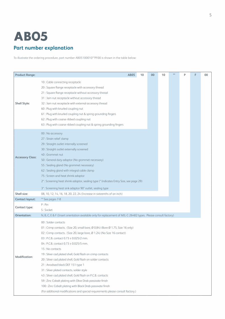
Part number explanation
AB05
Product Range: AB05 10 00 10 ** P F 00
Shell Style:
10 : Cable connecting receptacle
20 : Square flange receptacle with accessory thread
21 : Square flange receptacle without accessory thread
31 : Jam nut receptacle without accessory thread
32 : Jam nut receptacle with external accessory thread
60 : Plug with knurled coupling nut
61 : Plug with knurled coupling nut & spring grounding fingers
62 : Plug with coarse ribbed coupling nut
63 : Plug with coarse ribbed coupling nut & spring grounding fingers
Accessory Class:
00 : No accessory
27 : Strain relief clamp
29 : Straight outlet internally screened
30 : Straight outlet externally screened
40 : Grommet nut
50 : General duty adaptor (No grommet necessary)
55 : Sealing gland (No grommet necessary)
62 : Sealing gland with integral cable clamp
75 : Screen and heat shrink adaptor
2* : Screening heat shrink adaptor, sealing type (* Indicates Entry Size, see page 29)
3* : Screening heat sink adaptor 90° outlet, sealing type
Shell size: 08, 10, 12, 14, 16, 18, 20, 22, 24 (Increase in sixteenths of an inch)
Contact layout: ** See pages 7-8
Contact type:P : Pin
S : Socket
Orientation: N, B, C, E & F (Insert orientation available only for replacement of MIL-C-26482 types. Please consult factory)
Modification:
00 : Solder contacts
01 : Crimp contacts. (Size 20, small bore, Ø 0.84) (Bore Ø 1.75, Size 16 only)
02 : Crimp contacts. (Size 20, large bore, Ø 1.24) (No Size 16 contact)
03 : P.C.B. contact 0.73 ± 0.025/2 mm.
04 : P.C.B. contact 0.73 ± 0.025/5 mm.
15 : No contacts
19 : Silver cad plated shell, Gold flash on crimp contacts
20 : Silver cad plated shell, Gold flash on solder contacts
21 : Anodised black DEF 151 type 1
31 : Silver plated contacts, solder style
43 : Silver cad plated shell, Gold flash on P.C.B. contacts
59 : Zinc Cobalt plating with Olive Drab passivate finish
100 : Zinc Cobalt plating with Black Drab passivate finish
(For additional modifications and special requirements please consult factory.)
To illustrate the ordering procedure, part number AB05100010**PF00 is shown in the table below:
6
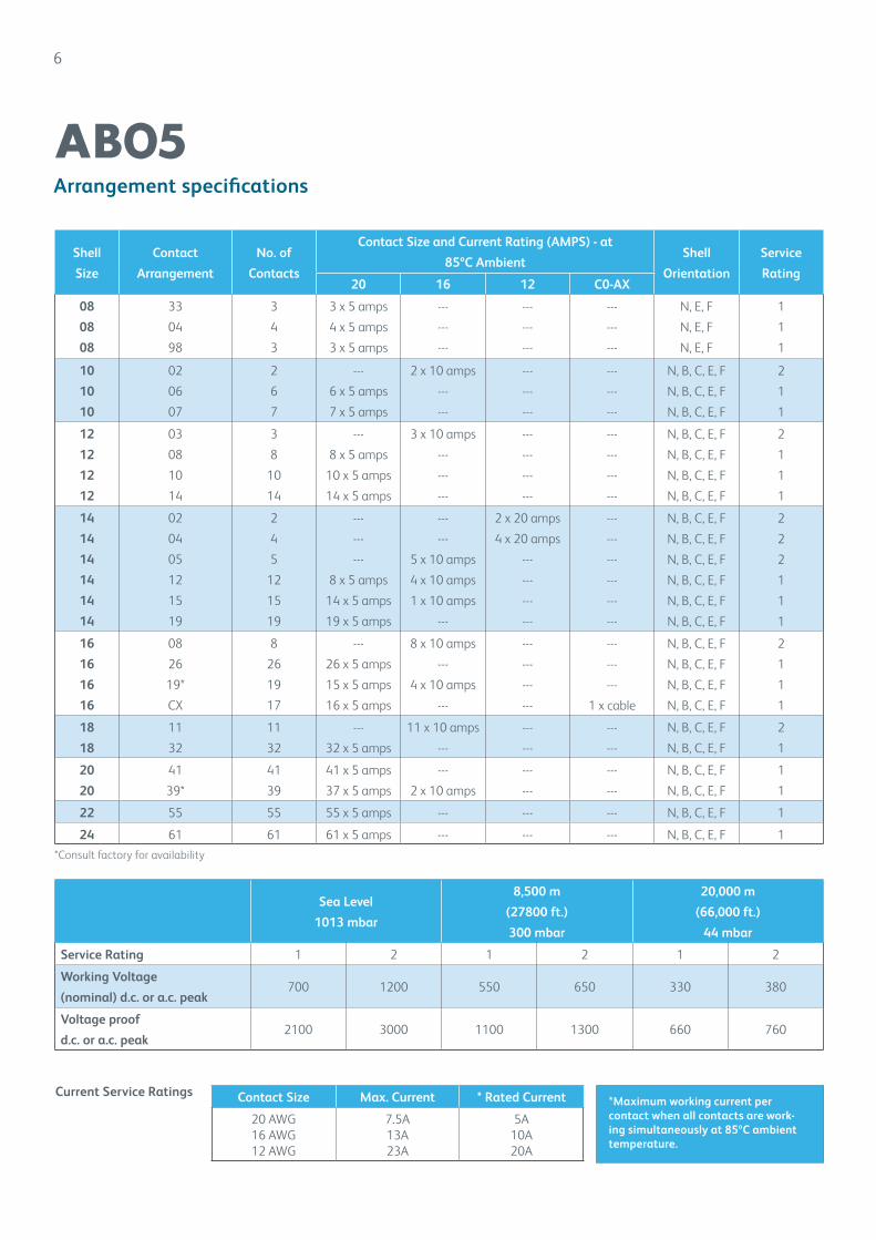
Arrangement specifications
AB05
Shell
Size
Contact
Arrangement
No. of
Contacts
Contact Size and Current Rating (AMPS) - at
85ºC AmbientShell
Orientation
Service
Rating20 16 12 C0-AX
08
08
08
33
04
98
3
4
3
3 x 5 amps
4 x 5 amps
3 x 5 amps
---
---
---
---
---
---
---
---
---
N, E, F
N, E, F
N, E, F
1
1
1
10
10
10
02
06
07
2
6
7
---
6 x 5 amps
7 x 5 amps
2 x 10 amps
---
---
---
---
---
---
---
---
N, B, C, E, F
N, B, C, E, F
N, B, C, E, F
2
1
1
12
12
12
12
03
08
10
14
3
8
10
14
---
8 x 5 amps
10 x 5 amps
14 x 5 amps
3 x 10 amps
---
---
---
---
---
---
---
---
---
---
---
N, B, C, E, F
N, B, C, E, F
N, B, C, E, F
N, B, C, E, F
2
1
1
1
14
14
14
14
14
14
02
04
05
12
15
19
2
4
5
12
15
19
---
---
---
8 x 5 amps
14 x 5 amps
19 x 5 amps
---
---
5 x 10 amps
4 x 10 amps
1 x 10 amps
---
2 x 20 amps
4 x 20 amps
---
---
---
---
---
---
---
---
---
---
N, B, C, E, F
N, B, C, E, F
N, B, C, E, F
N, B, C, E, F
N, B, C, E, F
N, B, C, E, F
2
2
2
1
1
1
16
16
16
16
08
26
19*
CX
8
26
19
17
---
26 x 5 amps
15 x 5 amps
16 x 5 amps
8 x 10 amps
---
4 x 10 amps
---
---
---
---
---
---
---
---
1 x cable
N, B, C, E, F
N, B, C, E, F
N, B, C, E, F
N, B, C, E, F
2
1
1
1
18
18
11
32
11
32
---
32 x 5 amps
11 x 10 amps
---
---
---
---
---
N, B, C, E, F
N, B, C, E, F
2
1
20
20
41
39*
41
39
41 x 5 amps
37 x 5 amps
---
2 x 10 amps
---
---
---
---
N, B, C, E, F
N, B, C, E, F
1
1
22 55 55 55 x 5 amps --- --- --- N, B, C, E, F 1
24 61 61 61 x 5 amps --- --- --- N, B, C, E, F 1
*Consult factory for availability
Sea Level
1013 mbar
8,500 m
(27800 ft.)
300 mbar
20,000 m
(66,000 ft.)
44 mbar
Service Rating 1 2 1 2 1 2
Working Voltage
(nominal) d.c. or a.c. peak700 1200 550 650 330 380
Voltage proof
d.c. or a.c. peak2100 3000 1100 1300 660 760
Contact Size Max. Current * Rated Current
20 AWG16 AWG12 AWG
7.5A13A23A
5A10A20A
Current Service Ratings*Maximum working current per contact when all contacts are work-ing simultaneously at 85ºC ambient temperature.
14-12
14-15
14-19
16-08
14-12
14-15
14-19
16-08
14-12
14-15
14-19
16-08
14-02
14-04
14-05
14-02
14-04
14-05
14-02
14-04
14-05
12-08
12-10
12-14
10-06
10-07
12-03
10-06
10-07
12-03
08-04
08-98
10-02
AB05 Insert Arrangements
Size 20 Contacts
Size 16 Contacts
Size 12 Contacts
Size 8 Contacts
Co-Axial Contact for RG316/U
Note: Views from front of pin connector inserts
08-02
08-33
Shell Size 8
7
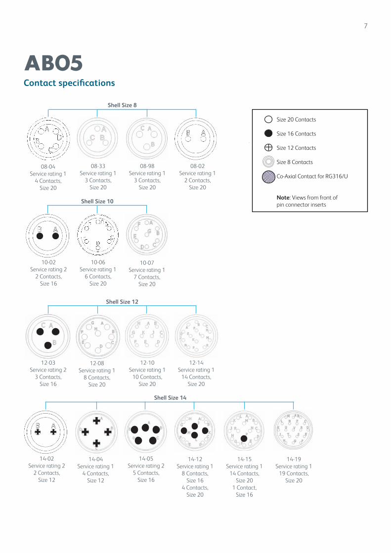
Contact specifications
AB05
08-33Service rating 1
3 Contacts, Size 20
08-04Service rating 1
4 Contacts, Size 20
10-02Service rating 2
2 Contacts, Size 16
10-06Service rating 1
6 Contacts, Size 20
10-07Service rating 1
7 Contacts, Size 20
Shell Size 10
12-03Service rating 2
3 Contacts, Size 16
12-08Service rating 1
8 Contacts, Size 20
12-10Service rating 1
10 Contacts, Size 20
14-05Service rating 2
5 Contacts, Size 16
14-12Service rating 1
8 Contacts, Size 16
4 Contacts,Size 20
14-19Service rating 1
19 Contacts, Size 20
Shell Size 12
Shell Size 14
08-98Service rating 1
3 Contacts, Size 20
12-14Service rating 1
14 Contacts, Size 20
14-02Service rating 2
2 Contacts, Size 12
14-04 Service rating 1
4 Contacts, Size 12
14-15Service rating 1
14 Contacts, Size 20
1 Contact,Size 16
Size 20 Contacts
Size 16 Contacts
Size 12 Contacts
Size 8 Contacts
Co-Axial Contact for RG316/U
Note: Views from front of pin connector inserts
AB05 Insert Arrangements
Size 20 Contacts
Size 16 Contacts
Size 12 Contacts
Size 8 Contacts
Co-Axial Contact for RG316/U
Note: Views from front of pin connector inserts
08-02
08-33
08-02Service rating 1
2 Contacts, Size 20
08-04
08-98
10-02
08-04
08-98
10-02
10-06
10-07
12-03
12-08
12-10
12-14
12-08
12-10
12-14
22-04
22-55
24-61
22-04
22-55
24-61
22-04
22-55
24-61
18-11
18-32
20-41
20-39
18-11
18-32
20-41
20-39
18-11
18-32
20-41
20-39
18-11
18-32
20-41
20-39
16-26
16-19
16-CX
18-02
16-26
16-19
16-CX
18-02
14-12
14-15
14-19
16-08
16-26
16-19
16-CX
18-02
8
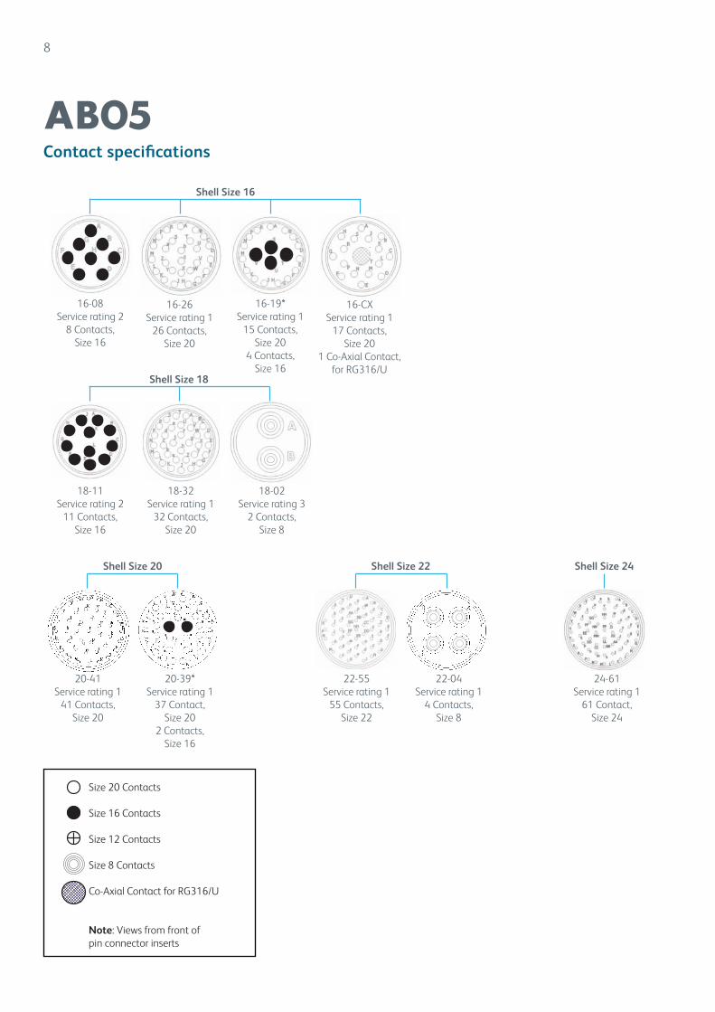
Contact specifications
AB05
Shell Size 24
16-08Service rating 2
8 Contacts, Size 16
16-26Service rating 1
26 Contacts, Size 20
18-11Service rating 2
11 Contacts, Size 16
18-32Service rating 1
32 Contacts, Size 20
20-41Service rating 1
41 Contacts, Size 20
20-39*Service rating 1
37 Contact, Size 20
2 Contacts,Size 16
Shell Size 16
Shell Size 18
Shell Size 20
22-55Service rating 1
55 Contacts, Size 22
24-61Service rating 1
61 Contact, Size 24
Shell Size 22
16-19*Service rating 1
15 Contacts, Size 20
4 Contacts,Size 16
16-CXService rating 1
17 Contacts, Size 20
1 Co-Axial Contact, for RG316/U
16-26
16-19
16-CX
18-02 18-02
Service rating 32 Contacts,
Size 8
22-04Service rating 1
4 Contacts, Size 8
Size 20 Contacts
Size 16 Contacts
Size 12 Contacts
Size 8 Contacts
Co-Axial Contact for RG316/U
Note: Views from front of pin connector inserts
Shell Size
A max.
B max.
C Ø max.
E max.
F thread UNEF 2A
H max.
Om min.overlap
MASSmax. G
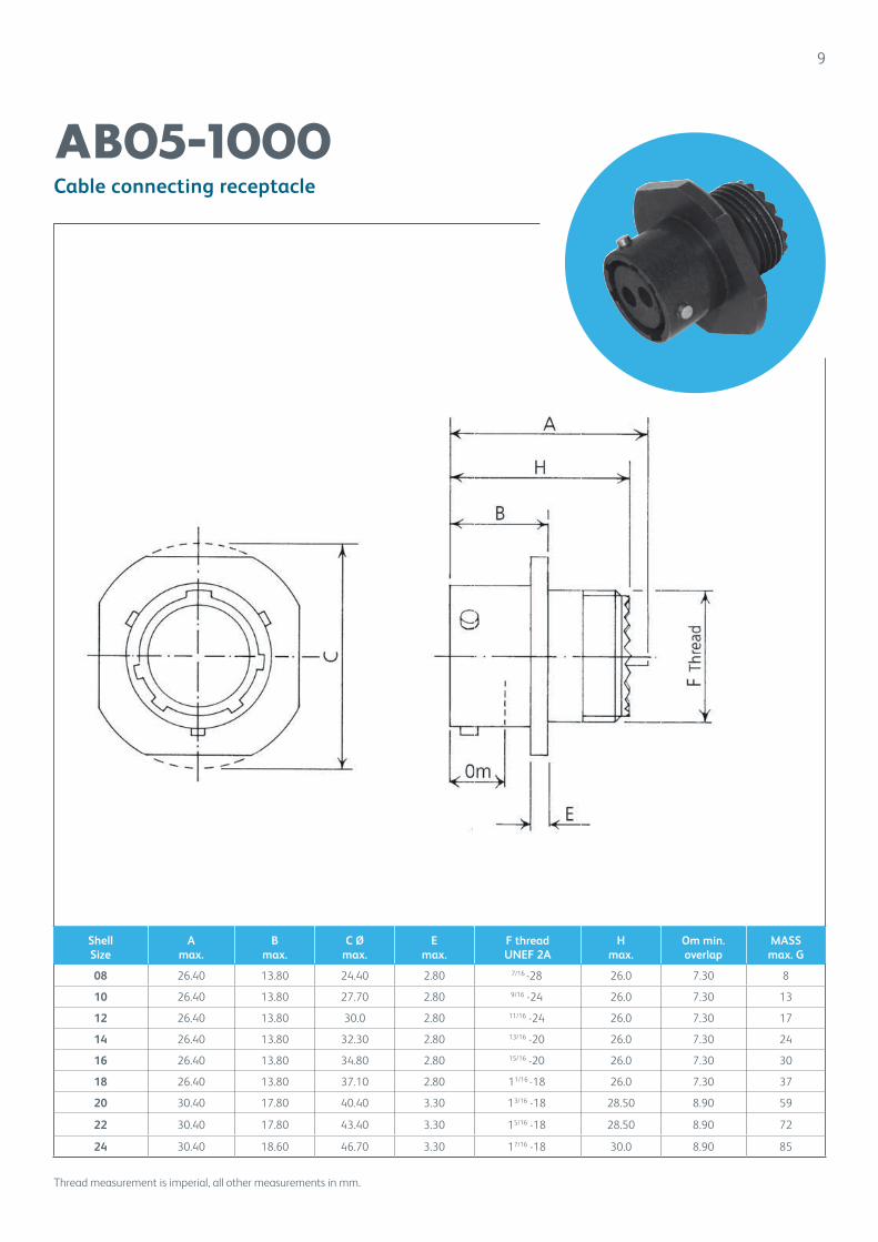
08 26.40 13.80 24.40 2.80 7/16 -28 26.0 7.30 8
10 26.40 13.80 27.70 2.80 9/16 -24 26.0 7.30 13
12 26.40 13.80 30.0 2.80 11/16 -24 26.0 7.30 17
14 26.40 13.80 32.30 2.80 13/16 -20 26.0 7.30 24
16 26.40 13.80 34.80 2.80 15/16 -20 26.0 7.30 30
18 26.40 13.80 37.10 2.80 11/16 -18 26.0 7.30 37
20 30.40 17.80 40.40 3.30 13/16 -18 28.50 8.90 59
22 30.40 17.80 43.40 3.30 15/16 -18 28.50 8.90 72
24 30.40 18.60 46.70 3.30 17/16 -18 30.0 8.90 85
9
Cable connecting receptacle
AB05-1000
Thread measurement is imperial, all other measurements in mm.
Shell Size
A max.
B max.
D sq. max.
E max.
F thread
UNEF 2AH max.
Om min.
overlapd1 Ømin.
d2 Ø min.
V min.
W ر0.13 (.005)
X (TP)
MASSmax. G
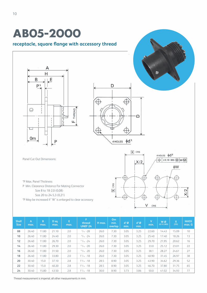
08 26.40 11.80 21.10 2.0 7/16 -28 26.0 7.30 3.05 3.25 22.60 14.43 15.09 10
10 26.40 11.80 24.40 2.0 9/16 -24 26.0 7.30 3.05 3.25 25.40 17.40 18.26 13
12 26.40 11.80 26.70 2.0 11/16 -24 26.0 7.30 3.05 3.25 29.70 21.95 20.62 16
14 26.40 11.80 29.30 2.0 13/16 -20 26.0 7.30 3.05 3.25 33.0 25.12 23.01 22
16 26.40 11.80 31.50 2.0 15/16 -20 26.0 7.30 3.05 3.25 38.1 28.27 24.61 27
18 26.40 11.80 33.80 2.0 11/16 -18 26.0 7.30 3.05 3.25 40.90 31.45 26.97 38
20 30.40 15.0 37.10 2.8 13/16 -18 28.5 8.90 3.05 3.25 43.90 34.62 29.36 52
22 30.40 15.0 40.20 2.8 15/16 -18 28.5 8.90 3.05 3.25 46.70 37.80 31.75 65
24 30.40 15.80 43.50 2.8 17/16 -18 30.0 8.90 3.73 3.86 50.0 41.02 34.93 77
10
receptacle, square flange with accessory thread
AB05-2000
Thread measurement is imperial, all other measurements in mm.
Panel Cut Out Dimensions:
*P Max. Panel Thickness
P Min. Clearance Distance For Mating Connector
Size 8 to 18-2,0 (0,08)
Size 20 to 24-5,3 (0,21)
*P May be increased if ‘W’ is enlarged to clear accessory
Shell Size A max. B max.C max.
E max.
H max.V CRS min.
W Ømin.
X CRS(TP)
d1 ر0.13(.005)
d2 ر0.13(.005)
Om min.
overlap
P max.
P1 max.
MASSmax. G
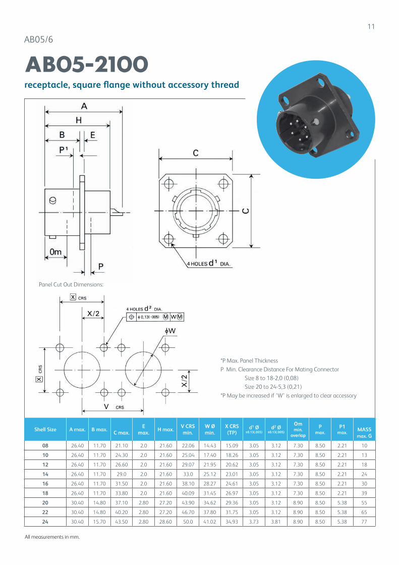
08 26.40 11.70 21.10 2.0 21.60 22.06 14.43 15.09 3.05 3.12 7.30 8.50 2.21 10
10 26.40 11.70 24.30 2.0 21.60 25.04 17.40 18.26 3.05 3.12 7.30 8.50 2.21 13
12 26.40 11.70 26.60 2.0 21.60 29.07 21.95 20.62 3.05 3.12 7.30 8.50 2.21 18
14 26.40 11.70 29.0 2.0 21.60 33.0 25.12 23.01 3.05 3.12 7.30 8.50 2.21 24
16 26.40 11.70 31.50 2.0 21.60 38.10 28.27 24.61 3.05 3.12 7.30 8.50 2.21 30
18 26.40 11.70 33.80 2.0 21.60 40.09 31.45 26.97 3.05 3.12 7.30 8.50 2.21 39
20 30.40 14.80 37.10 2.80 27.20 43.90 34.62 29.36 3.05 3.12 8.90 8.50 5.38 55
22 30.40 14.80 40.20 2.80 27.20 46.70 37.80 31.75 3.05 3.12 8.90 8.50 5.38 65
24 30.40 15.70 43.50 2.80 28.60 50.0 41.02 34.93 3.73 3.81 8.90 8.50 5.38 77
11
AB05/6
receptacle, square flange without accessory thread
AB05-2100
Panel Cut Out Dimensions:
*P Max. Panel Thickness
P Min. Clearance Distance For Mating Connector
Size 8 to 18-2,0 (0,08)
Size 20 to 24-5,3 (0,21)
*P May be increased if ‘W’ is enlarged to clear accessory
All measurements in mm.
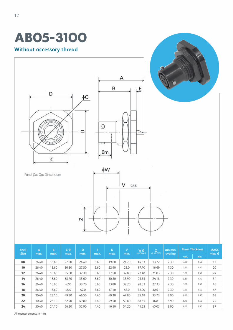
12
Without accessory thread
AB05-3100
Panel Cut Out Dimensions
All measurements in mm.
Shell Size
A max.
B max.
C Ømax.
D max.
E max.
Kmax.
V min.
W ر0.13(.005)
Z±0.13(.005)
Om min.overlap
Panel Thickness MASSmax. G
max. min.
08 26.40 18.60 27.50 24.40 3.60 19.60 24.70 14.53 13.72 7.30 3.30 1.50 17
10 26.40 18.60 30.80 27.50 3.60 22.90 28.0 17.70 16.69 7.30 3.30 1.50 20
12 26.40 18.60 35.60 32.30 3.60 27.50 32.80 22.48 21.03 7.30 3.30 1.50 24
14 26.40 18.60 38.70 35.60 3.60 30.80 35.90 25.65 24.18 7.30 3.30 1.50 34
16 26.40 18.60 42.0 38.70 3.60 33.80 39.20 28.83 27.33 7.30 3.30 1.50 43
18 26.40 18.60 45.0 42.0 3.60 37.10 43.0 32.00 30.61 7.30 3.30 1.50 47
20 30.40 23.10 49.80 46.50 4.40 40.20 47.80 35.18 33.73 8.90 6.40 1.50 63
22 30.40 23.10 52.90 49.80 4.40 49.50 50.80 38.35 36.81 8.90 6.40 1.50 74
24 30.40 24.10 56.20 52.90 4.40 46.50 54.20 41.53 40.03 8.90 6.40 1.50 87
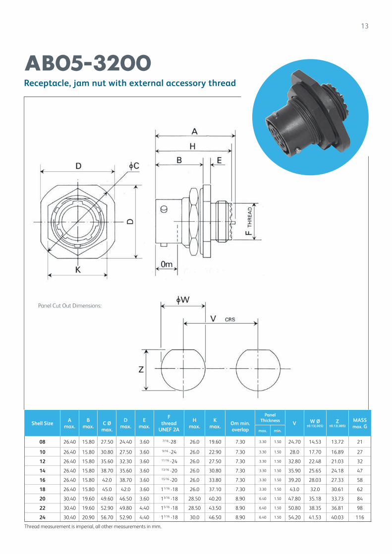
Shell SizeA
max.B
max.
C Ø
max.
D max.
E max.
F thread
UNEF 2A
H max.
K max.
Om min.overlap
Panel Thickness
V W ر0.13(.005)
Z±0.13(.005)
MASSmax. G
max. min.
08 26.40 15.80 27.50 24.40 3.60 7/16 -28 26.0 19.60 7.30 3.30 1.50 24.70 14.53 13.72 21
10 26.40 15.80 30.80 27.50 3.60 9/16 -24 26.0 22.90 7.30 3.30 1.50 28.0 17.70 16.89 27
12 26.40 15.80 35.60 32.30 3.60 11/16 -24 26.0 27.50 7.30 3.30 1.50 32.80 22.48 21.03 32
14 26.40 15.80 38.70 35.60 3.60 13/16 -20 26.0 30.80 7.30 3.30 1.50 35.90 25.65 24.18 47
16 26.40 15.80 42.0 38.70 3.60 15/16 -20 26.0 33.80 7.30 3.30 1.50 39.20 28.03 27.33 58
18 26.40 15.80 45.0 42.0 3.60 11/16 -18 26.0 37.10 7.30 3.30 1.50 43.0 32.0 30.61 62
20 30.40 19.60 49.60 46.50 3.60 13/16 -18 28.50 40.20 8.90 6.40 1.50 47.80 35.18 33.73 84
22 30.40 19.60 52.90 49.80 4.40 15/16 -18 28.50 43.50 8.90 6.40 1.50 50.80 38.35 36.81 98
24 30.40 20.90 56.70 52.90 4.40 17/16 -18 30.0 46.50 8.90 6.40 1.50 54.20 41.53 40.03 116
13
Receptacle, jam nut with external accessory thread
AB05-3200
Thread measurement is imperial, all other measurements in mm.
Panel Cut Out Dimensions:
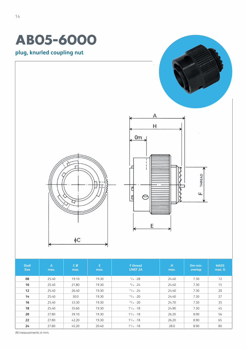
14
plug, knurled coupling nut
AB05-6000
All measurements in mm.
A
Shell Size
A max.
C Ø max.
E max.
F thread UNEF 2A
H max.
Om min.overlap
MASS max. G
08 25.40 19.10 19.30 7/16 -28 24.40 7.30 12
10 25.40 21.80 19.30 9/16 -24 24.40 7.30 15
12 25.40 26.40 19.30 11/16 -24 24.40 7.30 20
14 25.40 30.0 19.30 13/16 -20 24.40 7.30 27
16 25.40 33.30 19.30 15/16 -20 24.70 7.30 35
18 25.40 35.60 19.30 11/16 -18 24.90 7.30 45
20 27.80 39.10 19.30 13/16 -18 26.20 8.90 56
22 27.80 42.20 19.30 15/16 -18 26.20 8.90 65
24 27.80 45.20 20.40 17/16 -18 28.0 8.90 80
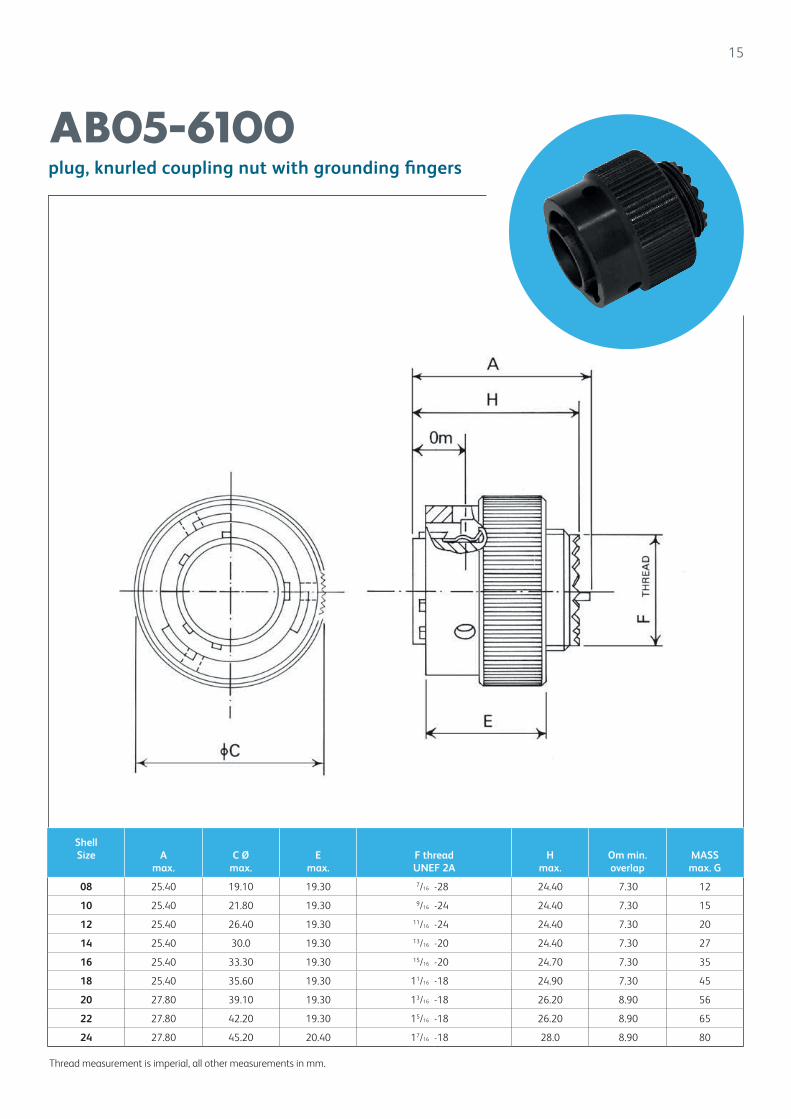
15
plug, knurled coupling nut with grounding fingers
AB05-6100
Thread measurement is imperial, all other measurements in mm.
Shell Size A
max.C Ø
max.E
max.F thread UNEF 2A
H max.
Om min.overlap
MASS max. G
08 25.40 19.10 19.30 7/16 -28 24.40 7.30 12
10 25.40 21.80 19.30 9/16 -24 24.40 7.30 15
12 25.40 26.40 19.30 11/16 -24 24.40 7.30 20
14 25.40 30.0 19.30 13/16 -20 24.40 7.30 27
16 25.40 33.30 19.30 15/16 -20 24.70 7.30 35
18 25.40 35.60 19.30 11/16 -18 24.90 7.30 45
20 27.80 39.10 19.30 13/16 -18 26.20 8.90 56
22 27.80 42.20 19.30 15/16 -18 26.20 8.90 65
24 27.80 45.20 20.40 17/16 -18 28.0 8.90 80
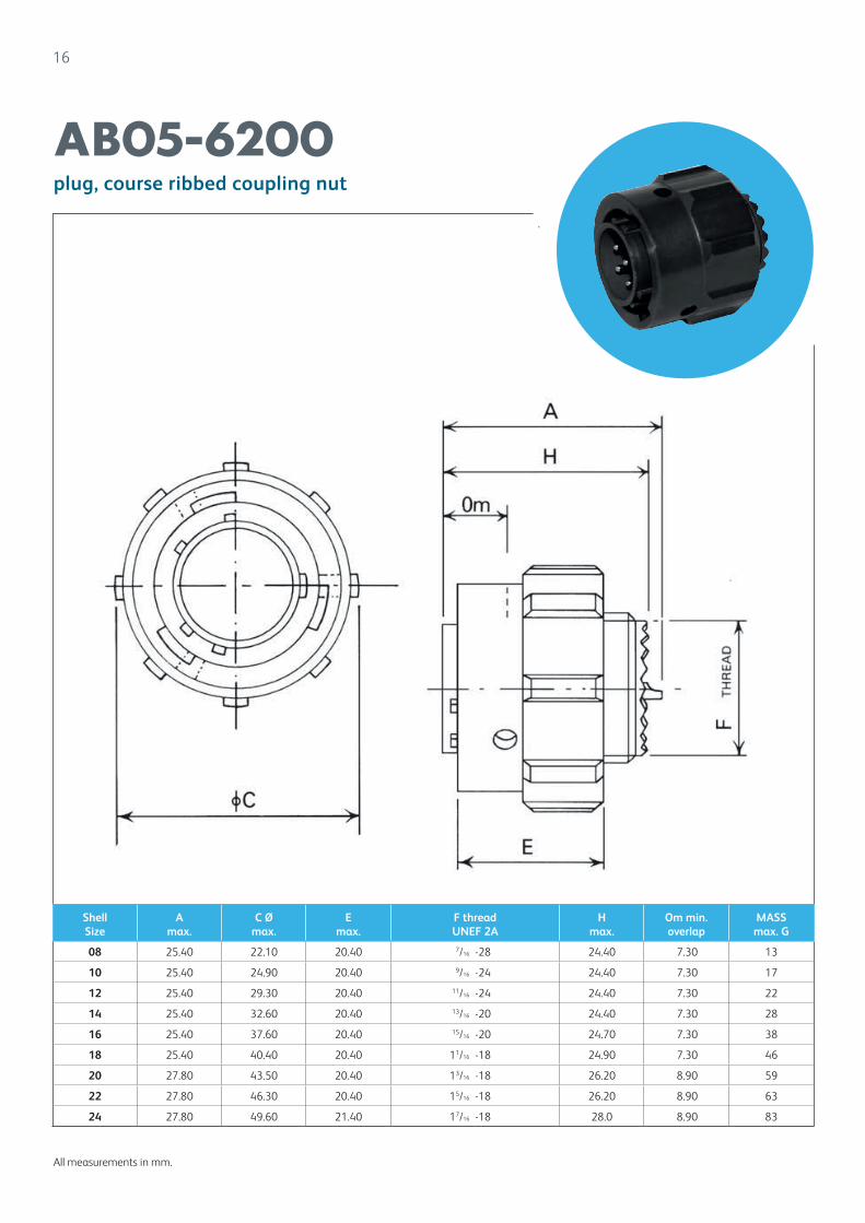
16
plug, course ribbed coupling nut
AB05-6200
All measurements in mm.
Shell Size
A max.
C Ø max.
E max.
F thread UNEF 2A
H max.
Om min.overlap
MASS max. G
08 25.40 22.10 20.40 7/16 -28 24.40 7.30 13
10 25.40 24.90 20.40 9/16 -24 24.40 7.30 17
12 25.40 29.30 20.40 11/16 -24 24.40 7.30 22
14 25.40 32.60 20.40 13/16 -20 24.40 7.30 28
16 25.40 37.60 20.40 15/16 -20 24.70 7.30 38
18 25.40 40.40 20.40 11/16 -18 24.90 7.30 46
20 27.80 43.50 20.40 13/16 -18 26.20 8.90 59
22 27.80 46.30 20.40 15/16 -18 26.20 8.90 63
24 27.80 49.60 21.40 17/16 -18 28.0 8.90 83
17
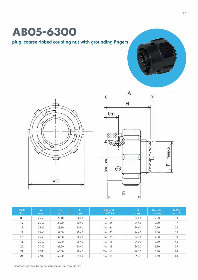
plug, coarse ribbed coupling nut with grounding fingers
AB05-6300
Thread measurement is imperial, all other measurements in mm.
Shell Size
A max.
C Ø max.
E max.
F thread UNEF 2A
H max.
Om min.overlap
MASS max. G
08 25.40 22.10 20.40 7/16 -28 24.40 7.30 13
10 25.40 24.90 20.40 9/16 -24 24.40 7.30 17
12 25.40 29.30 20.40 11/16 -24 24.40 7.30 22
14 25.40 32.60 20.40 13/16 -20 24.40 7.30 28
16 25.40 37.60 20.40 15/16 -20 24.70 7.30 38
18 25.40 40.40 20.40 11/16 -18 24.90 7.30 46
20 27.80 43.50 20.40 13/16 -18 26.20 8.90 59
22 27.80 46.30 20.40 15/16 -18 26.20 8.90 63
24 27.80 49.60 21.40 17/16 -18 28.0 8.90 83
18
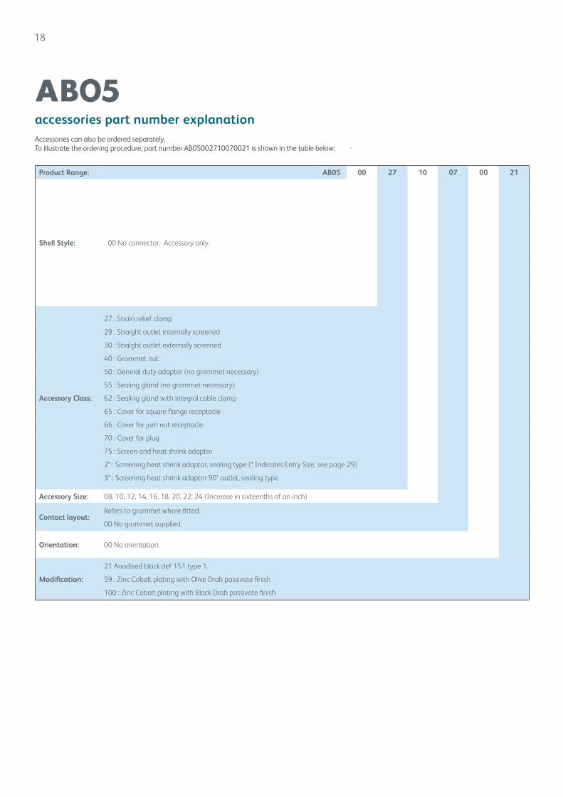
accessories part number explanation
AB05Accessories can also be ordered separately.To illustrate the ordering procedure, part number AB05002710070021 is shown in the table below:
Product Range: AB05 00 27 10 07 00 21
Shell Style: 00 No connector. Accessory only.
Accessory Class:
27 : Strain relief clamp
29 : Straight outlet internally screened
30 : Straight outlet externally screened
40 : Grommet nut
50 : General duty adaptor (no grommet necessary)
55 : Sealing gland (no grommet necessary)
62 : Sealing gland with integral cable clamp
65 : Cover for square flange receptacle
66 : Cover for jam nut receptacle
70 : Cover for plug
75 : Screen and heat shrink adaptor
2* : Screening heat shrink adaptor, sealing type (* Indicates Entry Size, see page 29)
3* : Screening heat shrink adaptor 90° outlet, sealing type
Accessory Size: 08, 10, 12, 14, 16, 18, 20, 22, 24 (Increase in sixteenths of an inch)
Contact layout:Refers to grommet where fitted.
00 No grommet supplied.
Orientation: 00 No orientation.
Modification:
21 Anodised black def 151 type 1.
59 : Zinc Cobalt plating with Olive Drab passivate finish
100 : Zinc Cobalt plating with Black Drab passivate finish
19
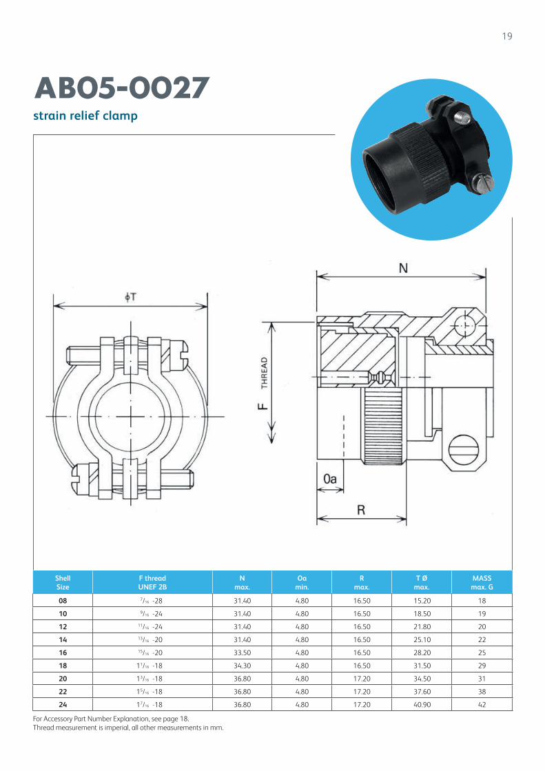
strain relief clamp
AB05-0027
For Accessory Part Number Explanation, see page 18.Thread measurement is imperial, all other measurements in mm.
Shell Size
F threadUNEF 2B
N max.
Oa min.
R max.
T Ø max.
MASS max. G
08 7/16 -28 31.40 4.80 16.50 15.20 18
10 9/16 -24 31.40 4.80 16.50 18.50 19
12 11/16 -24 31.40 4.80 16.50 21.80 20
14 13/16 -20 31.40 4.80 16.50 25.10 22
16 15/16 -20 33.50 4.80 16.50 28.20 25
18 11/16 -18 34.30 4.80 16.50 31.50 29
20 13/16 -18 36.80 4.80 17.20 34.50 31
22 15/16 -18 36.80 4.80 17.20 37.60 38
24 17/16 -18 36.80 4.80 17.20 40.90 42

20
straight outlet for internally screened cable
AB05-0029
For accessory part number explanation, see page 18
*Please consult factoryThread measurement is imperial, all other measurements in mm.
Shell Size
T Ømax.
F thread Ø
N max.
S Ø X A/F
08 17.53 7/16 x 28 51.30 7.20 12.70
10 19.30 9/16 x 24 51.05 8.70 12.70
12 21.74 11/16 x 24 63.30 7.20; 11.80 15.87
14 26.52 13/16 x 20 63.91 12.50 17.45
16 29.82 15/16 x 20 67.06 14.60 19.05
18 * * * * *
20 35.66 13/16 x 18 67.06 16.70 25.40
22 * * * * *
24 42.00 17/16 x 18 76.58 20.30 26.97
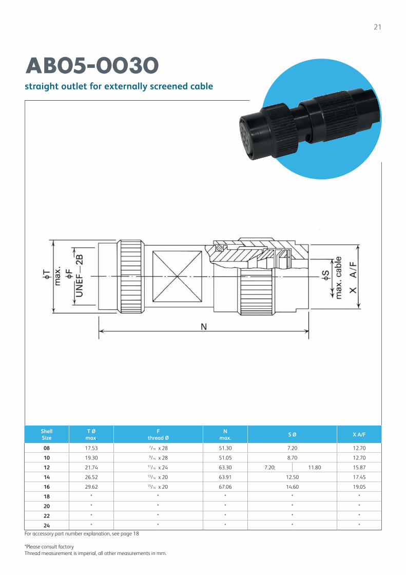
Shell Size
T Ømax.
F thread Ø
N max.
S Ø X A/F
08 17.53 7/16 x 28 51.30 7.20 12.70
10 19.30 9/16 x 28 51.05 8.70 12.70
12 21.74 11/16 x 24 63.30 7.20; 11.80 15.87
14 26.52 13/16 x 20 63.91 12.50 17.45
16 29.62 15/16 x 20 67.06 14.60 19.05
18 * * * * *
20 * * * * *
22 * * * * *
24 * * * * *
21
straight outlet for externally screened cable
AB05-0030
For accessory part number explanation, see page 18
*Please consult factoryThread measurement is imperial, all other measurements in mm.
22
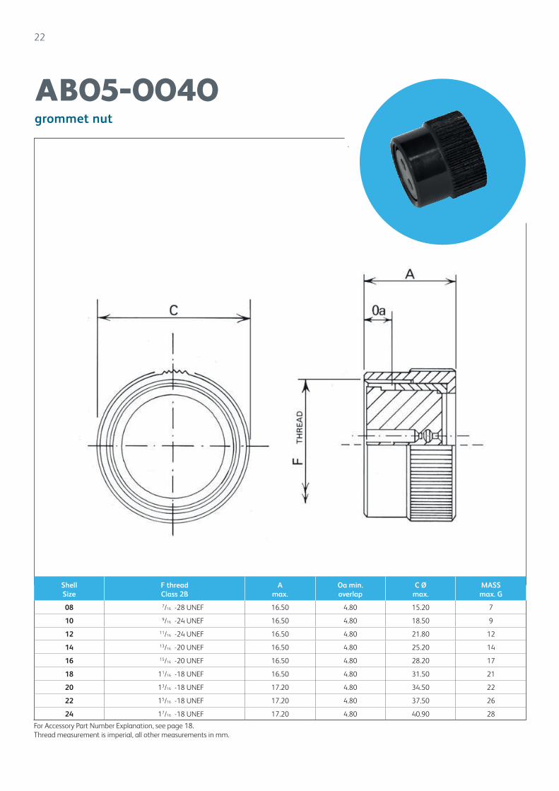
grommet nut
AB05-0040
Shell Size
F thread Class 2B
A max.
Oa min.overlap
C Ømax.
MASS max. G
08 7/16 -28 UNEF 16.50 4.80 15.20 7
10 9/16 -24 UNEF 16.50 4.80 18.50 9
12 11/16 -24 UNEF 16.50 4.80 21.80 12
14 13/16 -20 UNEF 16.50 4.80 25.20 14
16 15/16 -20 UNEF 16.50 4.80 28.20 17
18 11/16 -18 UNEF 16.50 4.80 31.50 21
20 13/16 -18 UNEF 17.20 4.80 34.50 22
22 15/16 -18 UNEF 17.20 4.80 37.50 26
24 17/16 -18 UNEF 17.20 4.80 40.90 28
For Accessory Part Number Explanation, see page 18.Thread measurement is imperial, all other measurements in mm.
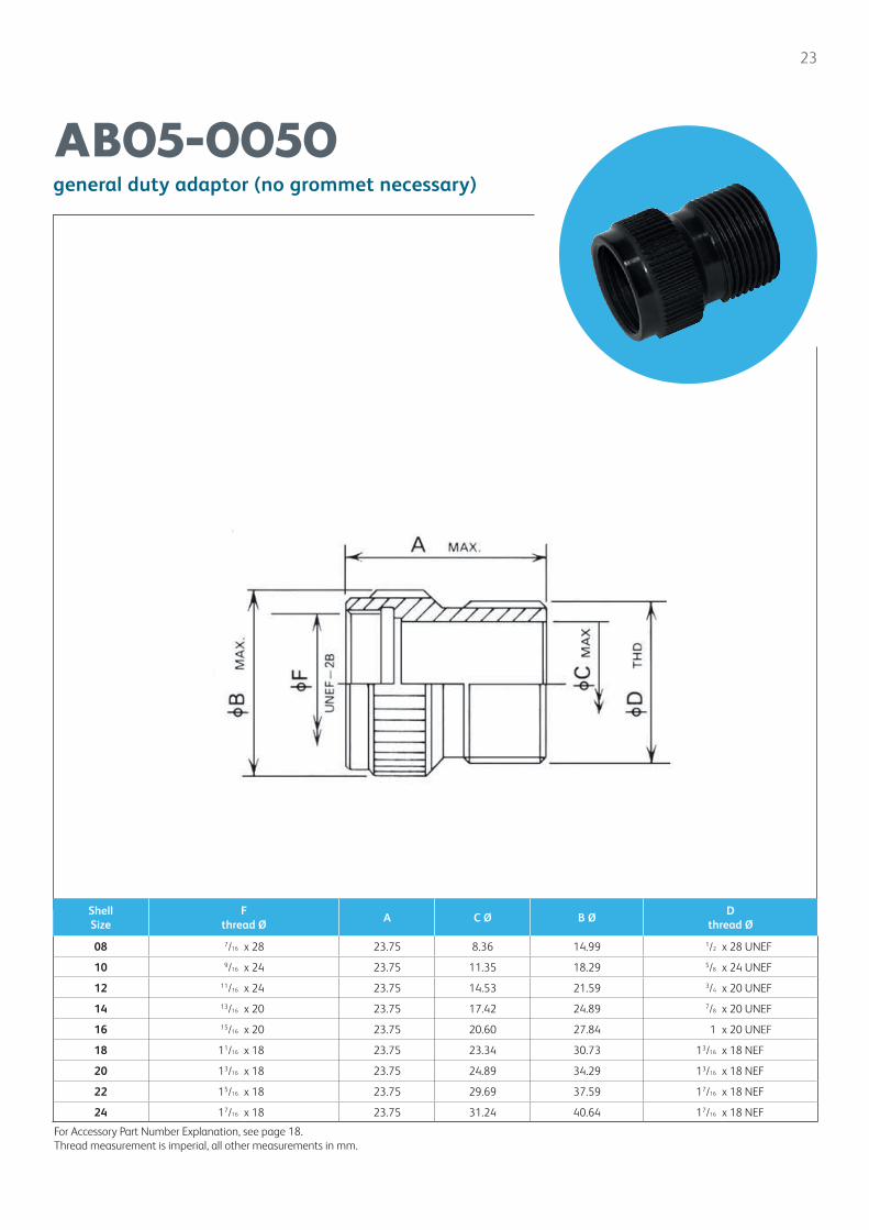
23
general duty adaptor (no grommet necessary)
AB05-0050
For Accessory Part Number Explanation, see page 18.Thread measurement is imperial, all other measurements in mm.
Shell Size
F thread Ø
A C Ø B ØD
thread Ø
08 7/16 x 28 23.75 8.36 14.99 1/2 x 28 UNEF
10 9/16 x 24 23.75 11.35 18.29 5/8 x 24 UNEF
12 11/16 x 24 23.75 14.53 21.59 3/4 x 20 UNEF
14 13/16 x 20 23.75 17.42 24.89 7/8 x 20 UNEF
16 15/16 x 20 23.75 20.60 27.84 1 x 20 UNEF
18 11/16 x 18 23.75 23.34 30.73 13/16 x 18 NEF
20 13/16 x 18 23.75 24.89 34.29 13/16 x 18 NEF
22 15/16 x 18 23.75 29.69 37.59 17/16 x 18 NEF
24 17/16 x 18 23.75 31.24 40.64 17/16 x 18 NEF
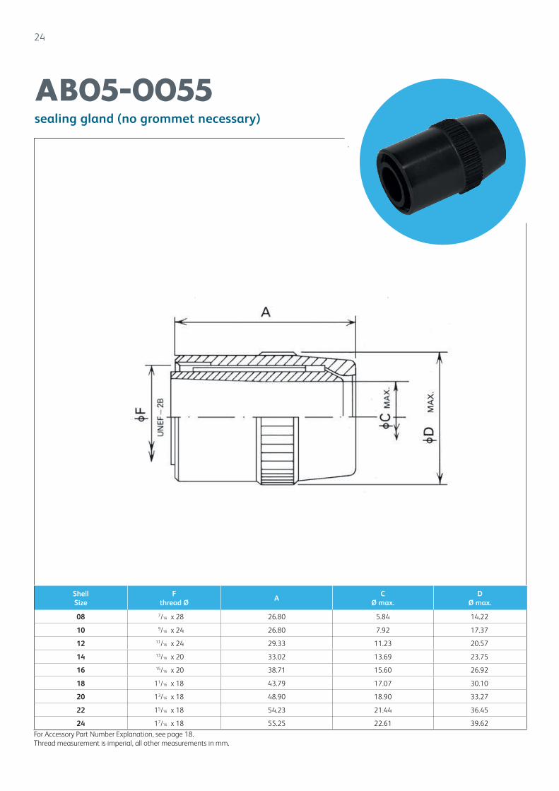
24
sealing gland (no grommet necessary)
AB05-0055
Shell Size
F thread Ø
A C
Ø max.D
Ø max.
08 7/16 x 28 26.80 5.84 14.22
10 9/16 x 24 26.80 7.92 17.37
12 11/16 x 24 29.33 11.23 20.57
14 13/16 x 20 33.02 13.69 23.75
16 15/16 x 20 38.71 15.60 26.92
18 11/16 x 18 43.79 17.07 30.10
20 13/16 x 18 48.90 18.90 33.27
22 15/16 x 18 54.23 21.44 36.45
24 17/16 x 18 55.25 22.61 39.62For Accessory Part Number Explanation, see page 18.Thread measurement is imperial, all other measurements in mm.
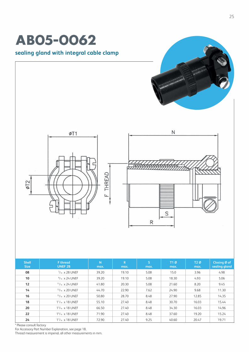
25
sealing gland with integral cable clamp
AB05-0062
Shell Size
F threadUNEF 2B
N max.
R max.
S max.
T1 Ømax.
T2 Ømax.
Closing Ø of sealing gland
08 7/16 x 28 UNEF 39.20 19.10 5.08 15.0 3.96 4.98
10 9/16 x 24 UNEF 39.20 19.10 5.08 18.30 4.93 5.06
12 11/16 x 24 UNEF 41.80 20.30 5.08 21.60 8.20 9.45
14 13/16 x 20 UNEF 44.70 22.90 7.62 24.90 9.68 11.30
16 15/16 x 20 UNEF 50.80 28.70 8.48 27.90 12.85 14.35
18 11/16 x 18 UNEF 55.10 27.40 8.48 30.70 16.03 15.44
20 13/16 x 18 UNEF 66.50 27.40 8.48 34.30 16.03 14.96
22 15/16 x 18 UNEF 71.90 27.40 8.48 37.60 19.20 15.24
24 17/16 x 18 UNEF 72.90 27.40 9.25 40.60 20.47 19.71
* Please consult factoryFor Accessory Part Number Explanation, see page 18.Thread measurement is imperial, all other measurements in mm.
26
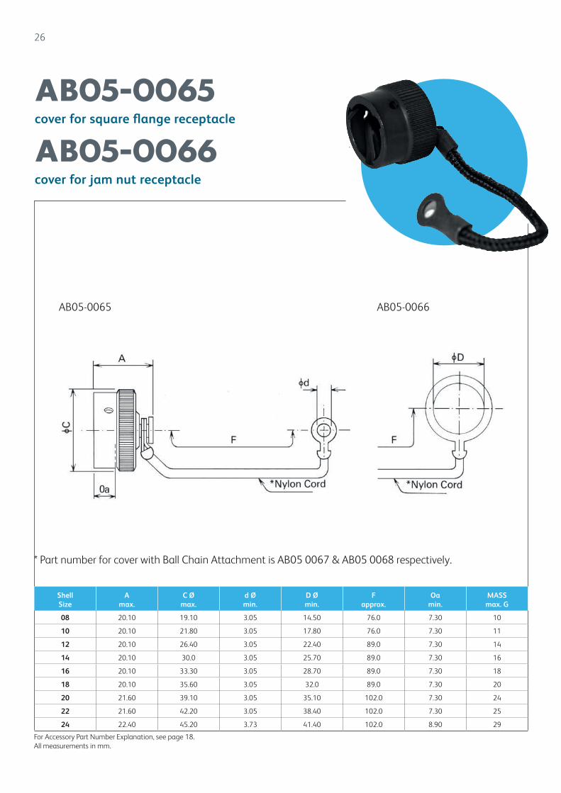
cover for square flange receptacle
cover for jam nut receptacle
AB05-0065
AB05-0066
Shell Size
Amax.
C Ømax.
d Ømin.
D Ømin.
Fapprox.
Oa min.
MASSmax. G
08 20.10 19.10 3.05 14.50 76.0 7.30 10
10 20.10 21.80 3.05 17.80 76.0 7.30 11
12 20.10 26.40 3.05 22.40 89.0 7.30 14
14 20.10 30.0 3.05 25.70 89.0 7.30 16
16 20.10 33.30 3.05 28.70 89.0 7.30 18
18 20.10 35.60 3.05 32.0 89.0 7.30 20
20 21.60 39.10 3.05 35.10 102.0 7.30 24
22 21.60 42.20 3.05 38.40 102.0 7.30 25
24 22.40 45.20 3.73 41.40 102.0 8.90 29
AB05-0065 AB05-0066
For Accessory Part Number Explanation, see page 18.All measurements in mm.
* Part number for cover with Ball Chain Attachment is AB05 0067 & AB05 0068 respectively.
27
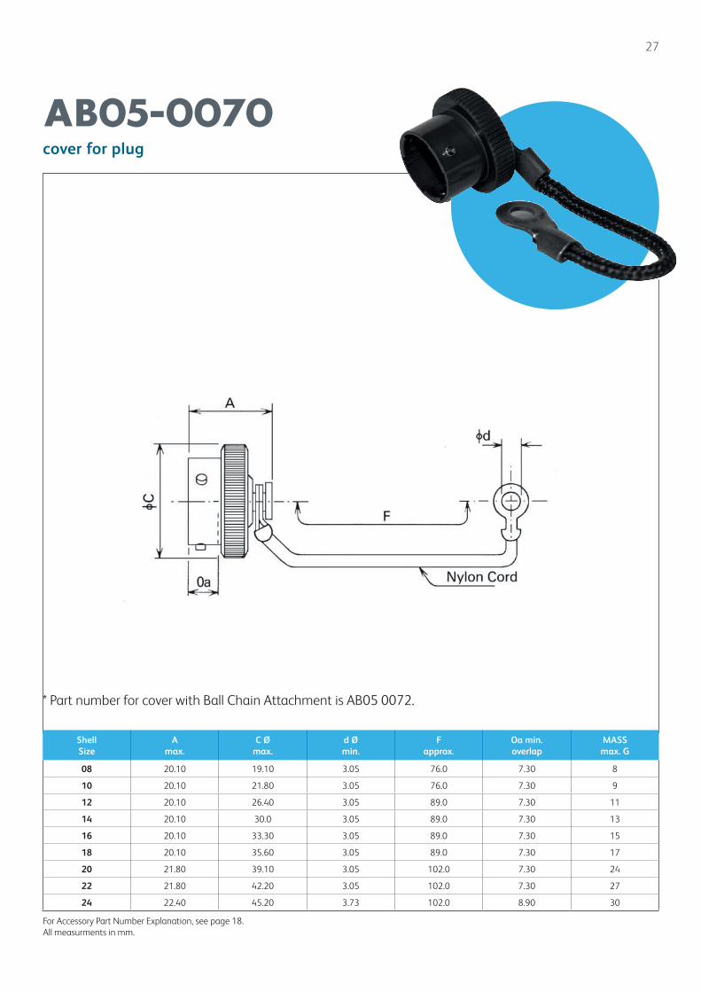
cover for plug
AB05-0070
Shell Size
Amax.
C Ømax.
d Ømin.
Fapprox.
Oa min.overlap
MASSmax. G
08 20.10 19.10 3.05 76.0 7.30 8
10 20.10 21.80 3.05 76.0 7.30 9
12 20.10 26.40 3.05 89.0 7.30 11
14 20.10 30.0 3.05 89.0 7.30 13
16 20.10 33.30 3.05 89.0 7.30 15
18 20.10 35.60 3.05 89.0 7.30 17
20 21.80 39.10 3.05 102.0 7.30 24
22 21.80 42.20 3.05 102.0 7.30 27
24 22.40 45.20 3.73 102.0 8.90 30
For Accessory Part Number Explanation, see page 18.All measurments in mm.
* Part number for cover with Ball Chain Attachment is AB05 0072.
28
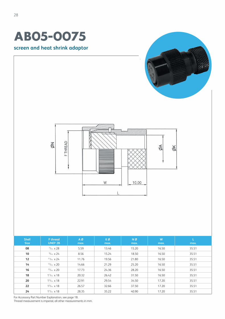
screen and heat shrink adaptor
AB05-0075
For Accessory Part Number Explanation, see page 18.Thread measurement is imperial, all other measurements in mm.
Shell Size
F threadUNEF 2B
A Ømax.
K Ømax.
N Ømax.
W max.
Lmax.
08 7/16 x 28 5.59 13.46 15.20 16.50 35.51
10 9/16 x 24 8.56 15.24 18.50 16.50 35.51
12 11/16 x 24 11.76 19.56 21.80 16.50 35.51
14 13/16 x 20 14.66 21.29 25.20 16.50 35.51
16 15/16 x 20 17.73 24.36 28.20 16.50 35.51
18 11/16 x 18 20.32 26.42 31.50 16.50 35.51
20 13/16 x 18 22.91 29.54 34.50 17.20 35.51
22 15/16 x 18 26.57 32.66 37.50 17.20 35.51
24 17/16 x 18 28.35 35.22 40.90 17.20 35.51
29
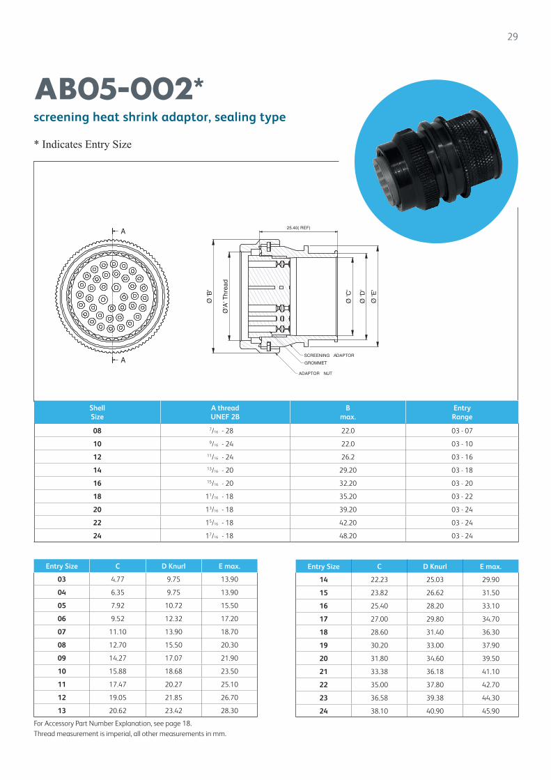
screening heat shrink adaptor, sealing type
* Indicates Entry Size
AB05-002*
Entry Size C D Knurl E max.
03 4.77 9.75 13.90
04 6.35 9.75 13.90
05 7.92 10.72 15.50
06 9.52 12.32 17.20
07 11.10 13.90 18.70
08 12.70 15.50 20.30
09 14.27 17.07 21.90
10 15.88 18.68 23.50
11 17.47 20.27 25.10
12 19.05 21.85 26.70
13 20.62 23.42 28.30
For Accessory Part Number Explanation, see page 18.Thread measurement is imperial, all other measurements in mm.
Shell Size
A threadUNEF 2B
Bmax.
Entry Range
08 7/16 - 28 22.0 03 - 07
10 9/16 - 24 22.0 03 - 10
12 11/16 - 24 26.2 03 - 16
14 13/16 - 20 29.20 03 - 18
16 15/16 - 20 32.20 03 - 20
18 11/16 - 18 35.20 03 - 22
20 13/16 - 18 39.20 03 - 24
22 15/16 - 18 42.20 03 - 24
24 17/16 - 18 48.20 03 - 24
Entry Size C D Knurl E max.
14 22.23 25.03 29.90
15 23.82 26.62 31.50
16 25.40 28.20 33.10
17 27.00 29.80 34.70
18 28.60 31.40 36.30
19 30.20 33.00 37.90
20 31.80 34.60 39.50
21 33.38 36.18 41.10
22 35.00 37.80 42.70
23 36.58 39.38 44.30
24 38.10 40.90 45.90
Ø'A
'Thr
ead
Ø'B
'
Ø'C
'
Ø'D
'
Ø'E
'
GROMMET
ADAPTORN UT
SCREENINGA DAPTOR
25.40( REF)
GA
RN
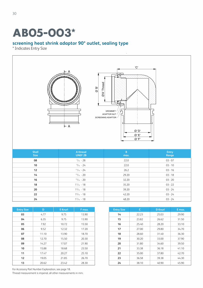
screening heat shrink adaptor 90º outlet, sealing type* Indicates Entry Size
30
AB05-003*
Shell Size
A threadUNEF 2B
Bmax.
Entry Range
08 7/16 - 28 22.0 03 - 07
10 9/16 - 24 22.0 03 - 10
12 11/16 - 24 26.2 03 - 16
14 13/16 - 20 29.20 03 - 18
16 15/16 - 20 32.20 03 - 20
18 11/16 - 18 35.20 03 - 22
20 13/16 - 18 39.20 03 - 24
22 15/16 - 18 42.20 03 - 24
24 17/16 - 18 48.20 03 - 24
Entry Size D E Knurl F max.
03 4.77 9.75 13.90
04 6.35 9.75 13.90
05 7.92 10.72 15.50
06 9.52 12.32 17.20
07 11.10 13.90 18.70
08 12.70 15.50 20.30
09 14.27 17.07 21.90
10 15.88 18.68 23.50
11 17.47 20.27 25.10
12 19.05 21.85 26.70
13 20.62 23.42 28.30
For Accessory Part Number Explanation, see page 18.Thread measurement is imperial, all other measurements in mm.
GROMMET
SCREENING ADAPTOR
ADAPTOR NUT
Ø 'D'
Ø 'E'Ø 'F'
Ø'A
'Thr
ead
Ø'B
'
'C'
Entry Size C D Knurl E max.
14 22.23 25.03 29.90
15 23.82 26.62 31.50
16 25.40 28.20 33.10
17 27.00 29.80 34.70
18 28.60 31.40 36.30
19 30.20 33.00 37.90
20 31.80 34.60 39.50
21 33.38 36.18 41.10
22 35.00 37.80 42.70
23 36.58 39.38 44.30
24 38.10 40.90 45.90
31
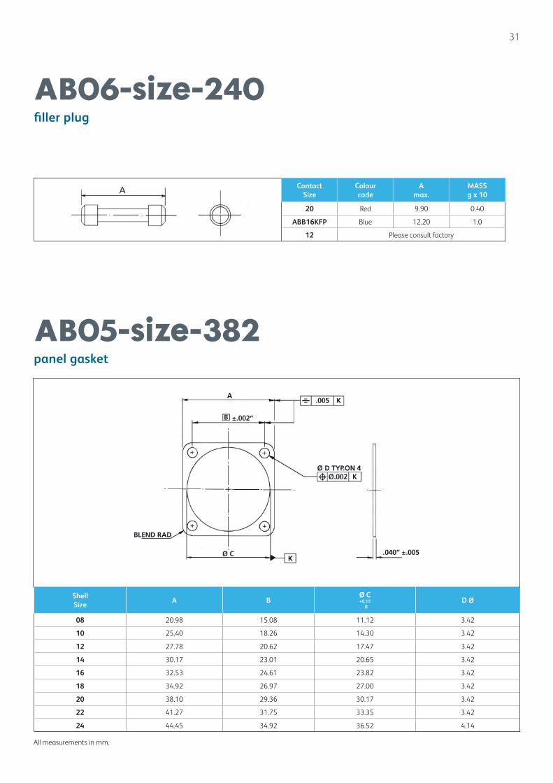
filler plug
panel gasket
AB06-size-240
AB05-size-382
Shell Size
A BØ C+0,15
- 0D Ø
08 20.98 15.08 11.12 3.42
10 25.40 18.26 14.30 3.42
12 27.78 20.62 17.47 3.42
14 30.17 23.01 20.65 3.42
16 32.53 24.61 23.82 3.42
18 34.92 26.97 27.00 3.42
20 38.10 29.36 30.17 3.42
22 41.27 31.75 33.35 3.42
24 44.45 34.92 36.52 4.14
All measurements in mm.
ContactSize
Colour code
Amax.
MASSg x 10
20 Red 9.90 0.40
ABB16KFP Blue 12.20 1.0
12 Please consult factory
32
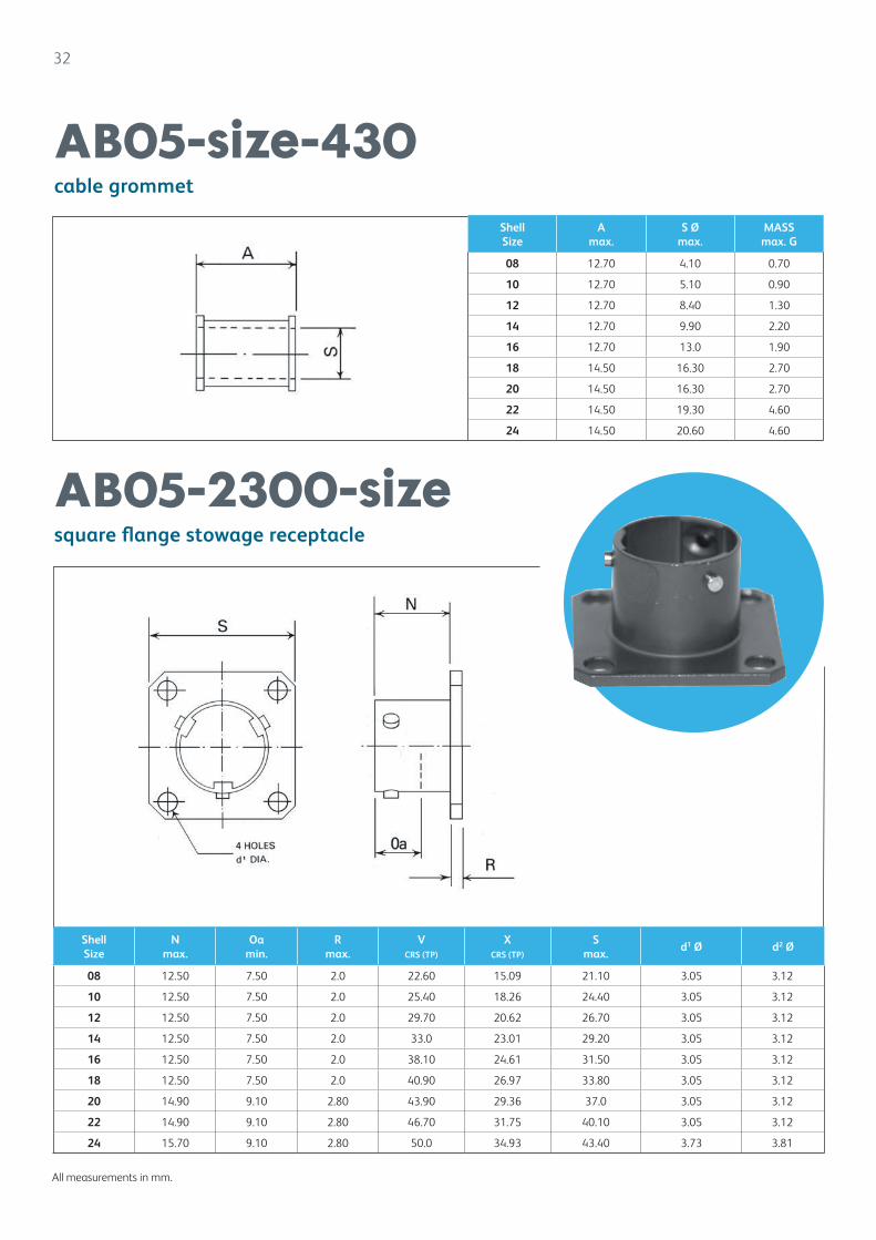
cable grommet
square flange stowage receptacle
AB05-size-430
AB05-2300-size
Shell Size
Nmax.
Oa min.
R max.
V CRS (TP)
X CRS (TP)
Smax.
d1 Ø d2 Ø
08 12.50 7.50 2.0 22.60 15.09 21.10 3.05 3.12
10 12.50 7.50 2.0 25.40 18.26 24.40 3.05 3.12
12 12.50 7.50 2.0 29.70 20.62 26.70 3.05 3.12
14 12.50 7.50 2.0 33.0 23.01 29.20 3.05 3.12
16 12.50 7.50 2.0 38.10 24.61 31.50 3.05 3.12
18 12.50 7.50 2.0 40.90 26.97 33.80 3.05 3.12
20 14.90 9.10 2.80 43.90 29.36 37.0 3.05 3.12
22 14.90 9.10 2.80 46.70 31.75 40.10 3.05 3.12
24 15.70 9.10 2.80 50.0 34.93 43.40 3.73 3.81
Shell Size
Amax.
S Ømax.
MASSmax. G
08 12.70 4.10 0.70
10 12.70 5.10 0.90
12 12.70 8.40 1.30
14 12.70 9.90 2.20
16 12.70 13.0 1.90
18 14.50 16.30 2.70
20 14.50 16.30 2.70
22 14.50 19.30 4.60
24 14.50 20.60 4.60
All measurements in mm.
33
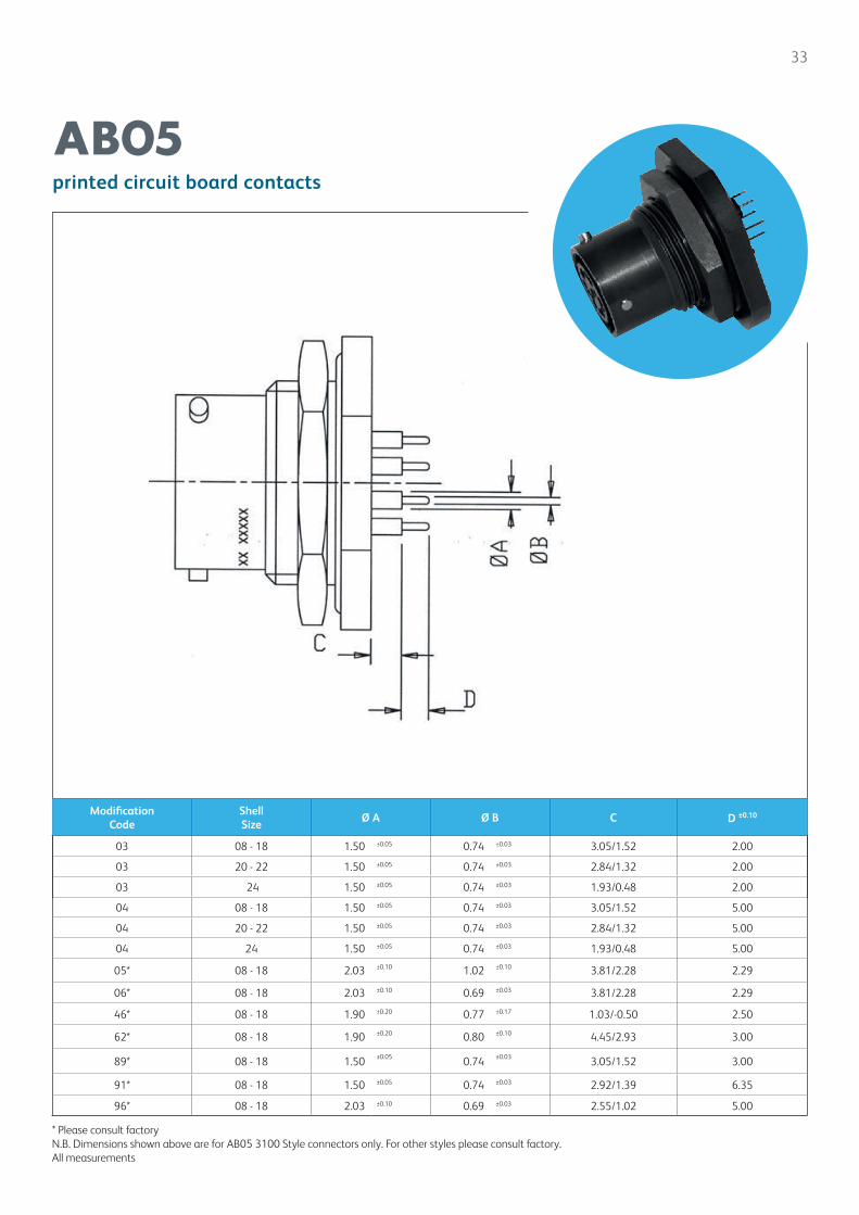
printed circuit board contacts
AB05
Modification Code
Shell Size
Ø A Ø B C D ±0.10
03 08 - 18 1.50 ±0.05 0.74 ±0.03 3.05/1.52 2.00
03 20 - 22 1.50 ±0.05 0.74 ±0.03 2.84/1.32 2.00
03 24 1.50 ±0.05 0.74 ±0.03 1.93/0.48 2.00
04 08 - 18 1.50 ±0.05 0.74 ±0.03 3.05/1.52 5.00
04 20 - 22 1.50 ±0.05 0.74 ±0.03 2.84/1.32 5.00
04 24 1.50 ±0.05 0.74 ±0.03 1.93/0.48 5.00
05* 08 - 18 2.03 ±0.10 1.02 ±0.10 3.81/2.28 2.29
06* 08 - 18 2.03 ±0.10 0.69 ±0.03 3.81/2.28 2.29
46* 08 - 18 1.90 ±0.20 0.77 ±0.17 1.03/-0.50 2.50
62* 08 - 18 1.90 ±0.20 0.80 ±0.10 4.45/2.93 3.00
89* 08 - 18 1.50 ±0.05 0.74 ±0.03 3.05/1.52 3.00
91* 08 - 18 1.50 ±0.05 0.74 ±0.03 2.92/1.39 6.35
96* 08 - 18 2.03 ±0.10 0.69 ±0.03 2.55/1.02 5.00
* Please consult factoryN.B. Dimensions shown above are for AB05 3100 Style connectors only. For other styles please consult factory.All measurements

34
crimp contacts and assembly tools
AB05
All measurements in mm.
Crimp tool and Positioner
Description Part No.
Crimp Tool ABBAF8 (M22520/01-01)
Positioner size 20 Pin and Socket
ABBTH1A
Positioner size 16 Pin and Socket
ABBTP1251
Contact Size AWG
AB Part Number Pin / Socket A Ø Conductor Sizes AWGShell Sizes
20 AB05-20-110GM Pin 0.84 28, 26, 24, 22 08 - 18
20 AB05-20-111GM Pin 0.84 28, 26, 24, 22 20 - 24
16 AB05-16-112GM Pin 1.75 16 08 - 18
20 AB05-20-112GM Pin 1.24 20 08 - 18
20 AB05-20-113GM Pin 1.24 20 20 - 24
20 AB05-20-114GM Pin 1.35 18 08 - 18
20 AB05-20-115GM Pin 1.35 18 20 - 24
20 AB05-151-20 Socket 1.83 14 08 - 18
20 AB05-103-20 Socket 0.84 28, 26, 24, 22 08 - 18
20 AB05-152-20 Socket 0.84 28, 26, 24, 22 20 - 24
16 AB05-103-16 Socket 1.75 16 08 - 18
20 AB05-104-20 Socket 1.24 20 08 - 18
20 AB05-153-20 Socket 1.24 20 20 - 24
20 AB05-154-20 Socket 1.35 18 20 - 24
20 AB05-156-20 Socket 1.35 18 08 - 18
35
assembly procedure for straight outlets
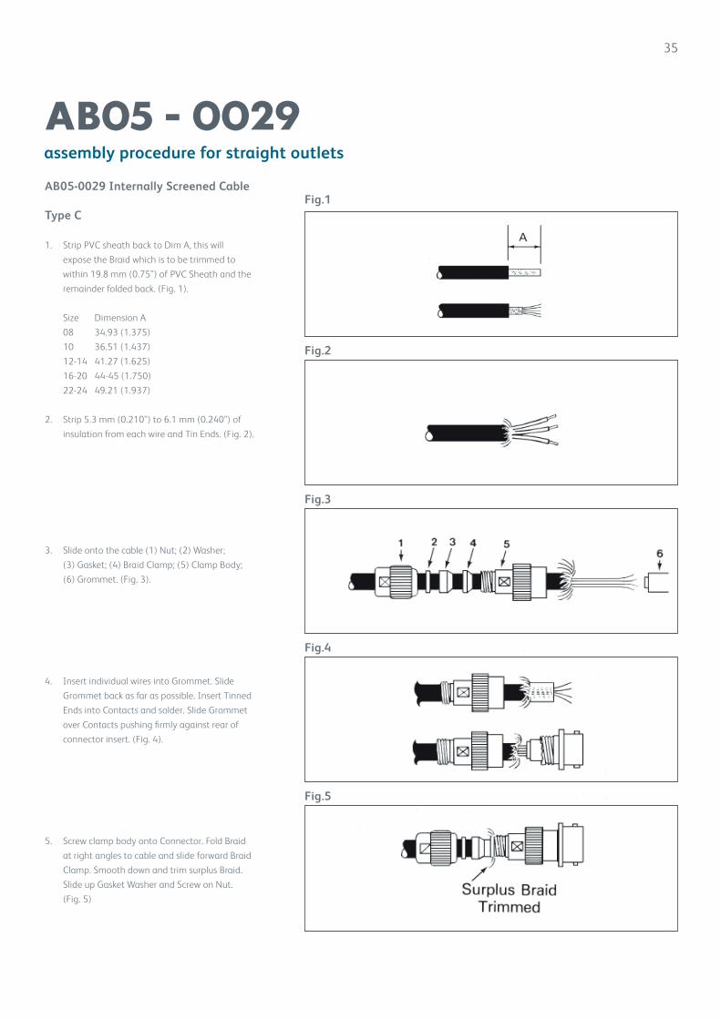
AB05 - 0029AB05-0029 Internally Screened Cable
Type C
1. Strip PVC sheath back to Dim A, this will
expose the Braid which is to be trimmed to
within 19.8 mm (0.75”) of PVC Sheath and the
remainder folded back. (Fig. 1).
Size Dimension A
08 34.93 (1.375)
10 36.51 (1.437)
12-14 41.27 (1.625)
16-20 44-45 (1.750)
22-24 49.21 (1.937)
2. Strip 5.3 mm (0.210”) to 6.1 mm (0.240”) of
insulation from each wire and Tin Ends. (Fig. 2).
3. Slide onto the cable (1) Nut; (2) Washer;
(3) Gasket; (4) Braid Clamp; (5) Clamp Body;
(6) Grommet. (Fig. 3).
4. Insert individual wires into Grommet. Slide
Grommet back as far as possible. Insert Tinned
Ends into Contacts and solder. Slide Grommet
over Contacts pushing firmly against rear of
connector insert. (Fig. 4).
5. Screw clamp body onto Connector. Fold Braid
at right angles to cable and slide forward Braid
Clamp. Smooth down and trim surplus Braid.
Slide up Gasket Washer and Screw on Nut.
(Fig. 5)
Fig.1
Fig.2
Fig.3
Fig.4
Fig.5
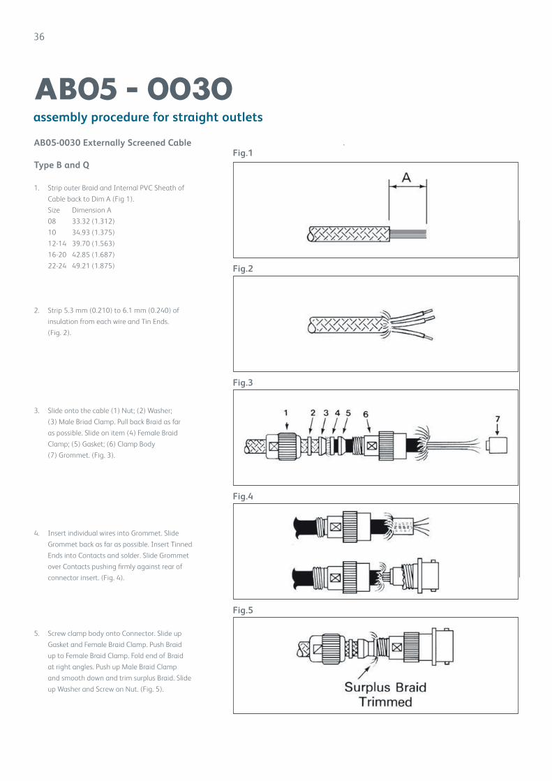
AB05-0030 Externally Screened Cable
Type B and Q
1. Strip outer Braid and Internal PVC Sheath of
Cable back to Dim A (Fig 1).
Size Dimension A
08 33.32 (1.312)
10 34.93 (1.375)
12-14 39.70 (1.563)
16-20 42.85 (1.687)
22-24 49.21 (1.875)
2. Strip 5.3 mm (0.210) to 6.1 mm (0.240) of
insulation from each wire and Tin Ends.
(Fig. 2).
3. Slide onto the cable (1) Nut; (2) Washer;
(3) Male Briad Clamp. Pull back Braid as far
as possible. Slide on item (4) Female Braid
Clamp; (5) Gasket; (6) Clamp Body
(7) Grommet. (Fig. 3).
4. Insert individual wires into Grommet. Slide
Grommet back as far as possible. Insert Tinned
Ends into Contacts and solder. Slide Grommet
over Contacts pushing firmly against rear of
connector insert. (Fig. 4).
5. Screw clamp body onto Connector. Slide up
Gasket and Female Braid Clamp. Push Braid
up to Female Braid Clamp. Fold end of Braid
at right angles. Push up Male Braid Clamp
and smooth down and trim surplus Braid. Slide
up Washer and Screw on Nut. (Fig. 5).
36
AB05 - 0030assembly procedure for straight outlets
Fig.1
Fig.2
Fig.3
Fig.4
Fig.5

37
Miniature Bayonet Coupling Connectors
AB05 10-76
The AB05 10-76 Miniature Bayonet Coupling Connectors have been specifically designed to be backward compatible with the Clansman 10-07.
AB05 10-76 has a plating finish of zinc cobalt olive drab a benefit of this is a high resistance to corrosion which has been dictated on Bowman in the UK.
Shell size 10 is used throughout the connector range and contact arrangements consist only of 7 size 20 contacts and 6 size 22 contacts. Insulators are thermoplastic with an operating temperature range of -55ºC to 125ºC.
Shells are keyed to prevent miss mating between shells of different orientations. Designation F is for Radio Audio, N for Data and E for Ethernet. Other orientations available are B and C.
Contents Page
AB05 10-76 Miniature Bayonet Coupling Connectors 37-41
Technical Information 38
Part No. Explanation 39
Receptacles;-76 Miniature Bayonet Coupling Connectors
AB06 3100 10 76 SF 152: receptacle, panel mounting with PC printed circuit terminals 41
AB06 3100 10 76 SF 221: receptacle, panel cut out with solder contacts 42
Plugs;
AB05 5700 10 76 PF 217: plug, knurled coupling nut 40
AB05 8500 10 76 PC 220: plug, with over moulding back shell and solder contacts 40
AB06 Audio Miniature Bayonet Lock Connectors Range 43-61
Safety Information 62
38
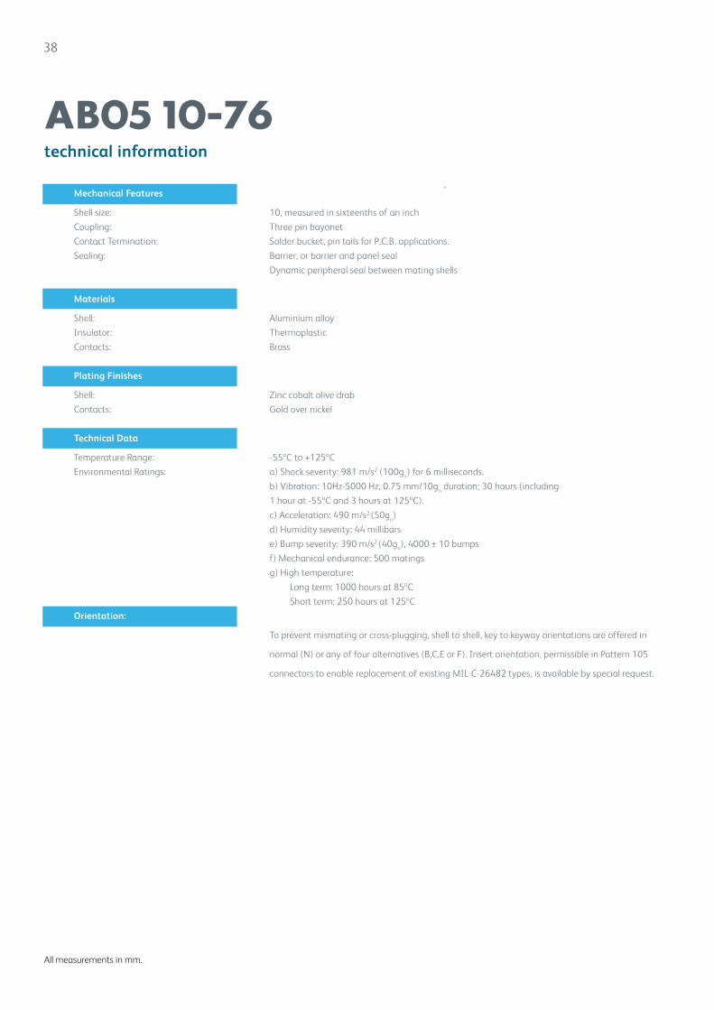
technical information
AB05 10-76
All measurements in mm.
Mechanical Features
Shell size: 10, measured in sixteenths of an inch
Coupling: Three pin bayonet
Contact Termination: Solder bucket, pin tails for P.C.B. applications.
Sealing: Barrier, or barrier and panel seal
Dynamic peripheral seal between mating shells
Materials
Shell: Aluminium alloy
Insulator: Thermoplastic
Contacts: Brass
Plating Finishes
Shell: Zinc cobalt olive drab
Contacts: Gold over nickel
Technical Data
Temperature Range: -55ºC to +125ºC
Environmental Ratings: a) Shock severity: 981 m/s2 (100gn) for 6 milliseconds.
b) Vibration: 10Hz-5000 Hz, 0.75 mm/10gn duration; 30 hours (including
1 hour at -55ºC and 3 hours at 125ºC).
c) Acceleration: 490 m/s2 (50gn)
d) Humidity severity: 44 millibars
e) Bump severity: 390 m/s2 (40gn), 4000 ± 10 bumps
f) Mechanical endurance: 500 matings
g) High temperature:
Long term: 1000 hours at 85ºC
Short term: 250 hours at 125ºC
Orientation:
To prevent mismating or cross-plugging, shell to shell, key to keyway orientations are offered in
normal (N) or any of four alternatives (B,C,E or F). Insert orientation, permissible in Pattern 105
connectors to enable replacement of existing MIL-C-26482 types, is available by special request.
39
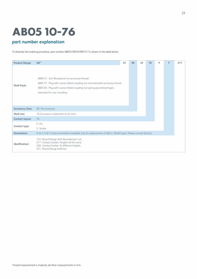
part number explanation
AB05 10-76
Thread measurement is imperial, all other measurements in mm.
To illustrate the ordering procedure, part number AB0557001076PF217 is shown in the table below:
Product Range: AB** 57 00 10 76 P F 217
Shell Style:
AB06 31 : Jam Receptacle (no accessory thread)
AB05 57 : Plug with coarse ribbed coupling nut and extended accessory thread
AB05 85 : Plug with coarse ribbed coupling nut spring grounding fingers
extended for over moulding
Accessory Class: 00 : No accessory
Shell size: 10 (Increase in sixteenths of an inch)
Contact layout: 76
Contact type:P : Pin
S : Socket
Orientation: N, B, C, E & F (Insert orientation available only for replacement of MIL-C-26482 types. Please consult factory)
Modification:
152 : Round flange shell. Rounded jam nut.217 : Contact bucket. Heights all the same.220 : Contact bucket. At different heights.221 : Round flange shell hex.
40
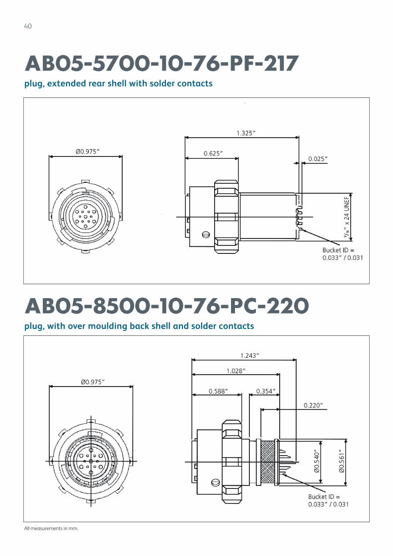
plug, extended rear shell with solder contacts
plug, with over moulding back shell and solder contacts
AB05-5700-10-76-PF-217
AB05-8500-10-76-PC-220
All measurements in mm.
41
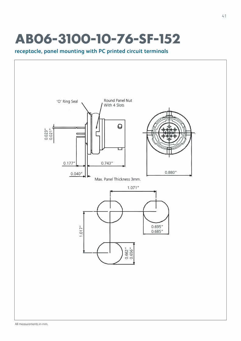
receptacle, panel mounting with PC printed circuit terminals
AB06-3100-10-76-SF-152
All measurements in mm.
42
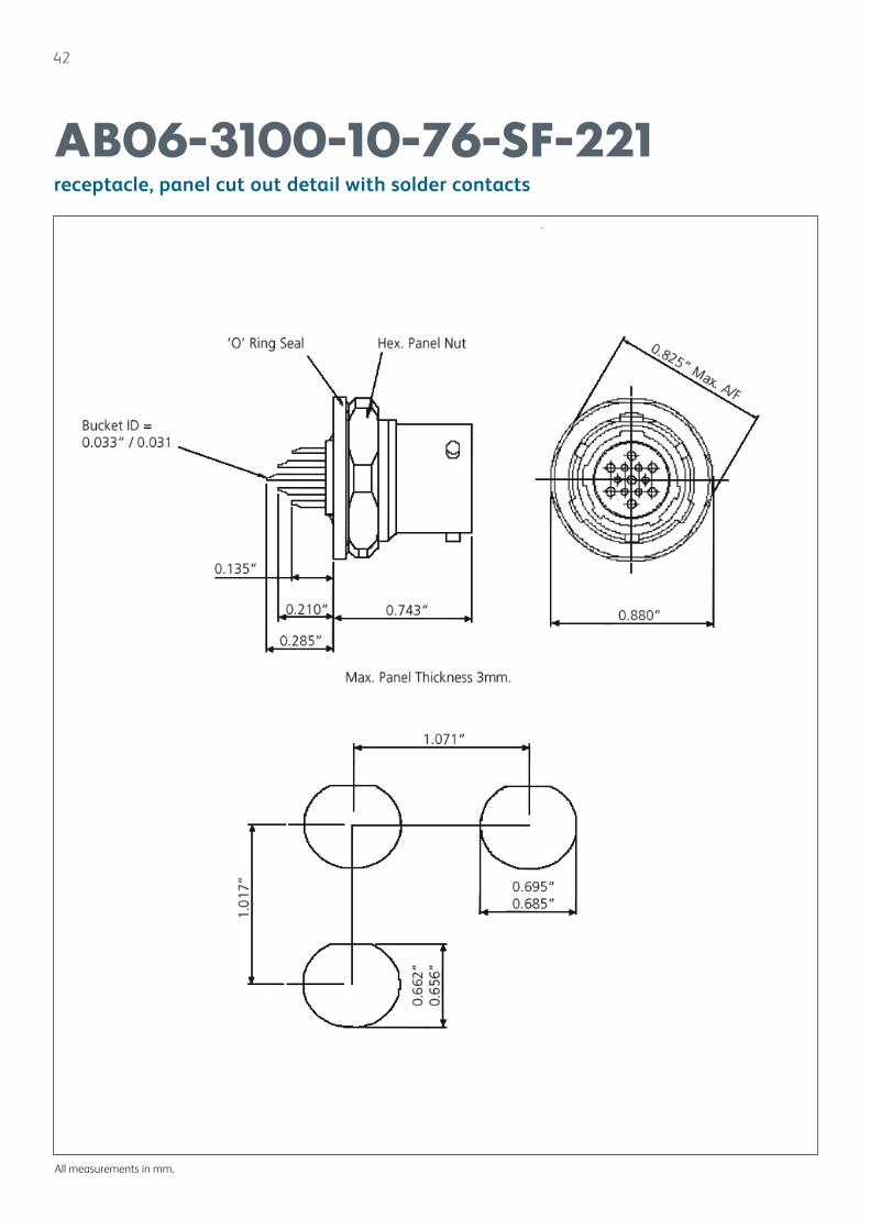
receptacle, panel cut out detail with solder contacts
AB06-3100-10-76-SF-221
All measurements in mm.

43
Audio Miniature Bayonet Lock Connectors
AB06AB06 connectors are a development of the established AB05 (Patt, 105) range and are particularly suitable for tinsel cordage applications in audio equipment.
Designed to requirements of the Royal Signals and Radar Establishment, AB06 connectors are available in shell sizes 8, 10 and 12, and offer all performance characteristics and design features of AB05 connectors. An alternative ‘snatch’ type coupling nut for quick release applications is available in shell size 10.
Shell styles available are: free cable mounted with course ribbed or ‘snatch’ coupling nut, fixed single hole mount. fixed single hole mount ‘audio’ (thinner mounting flange) and free coupler connector. Contact styles are solder bucket, crimp and p.c.b mounted.
Accessories include a straight outlet with a polychloroprene sleeve for tinsel cordage, 90º outlets and protective caps.

44
Audio Miniature Bayonet Lock Connectors
AB06
Contents Page
AB06 Audio Miniature Bayonet Lock Connectors 43-59
Technical Information 45
Part No. Explanation 46
Arrangement Specifications 47
Contact Arrangements 47
Connectors
AB06 1000: coupler connector with accessory thread 48
AB06 3100: fixed connector single hole mounting 49
AB06 3200: fixed connector single hole mounting with accessory thread 50
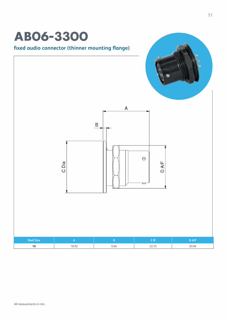
AB06 3300: fixed audio connector (thinner mounting flange) 51
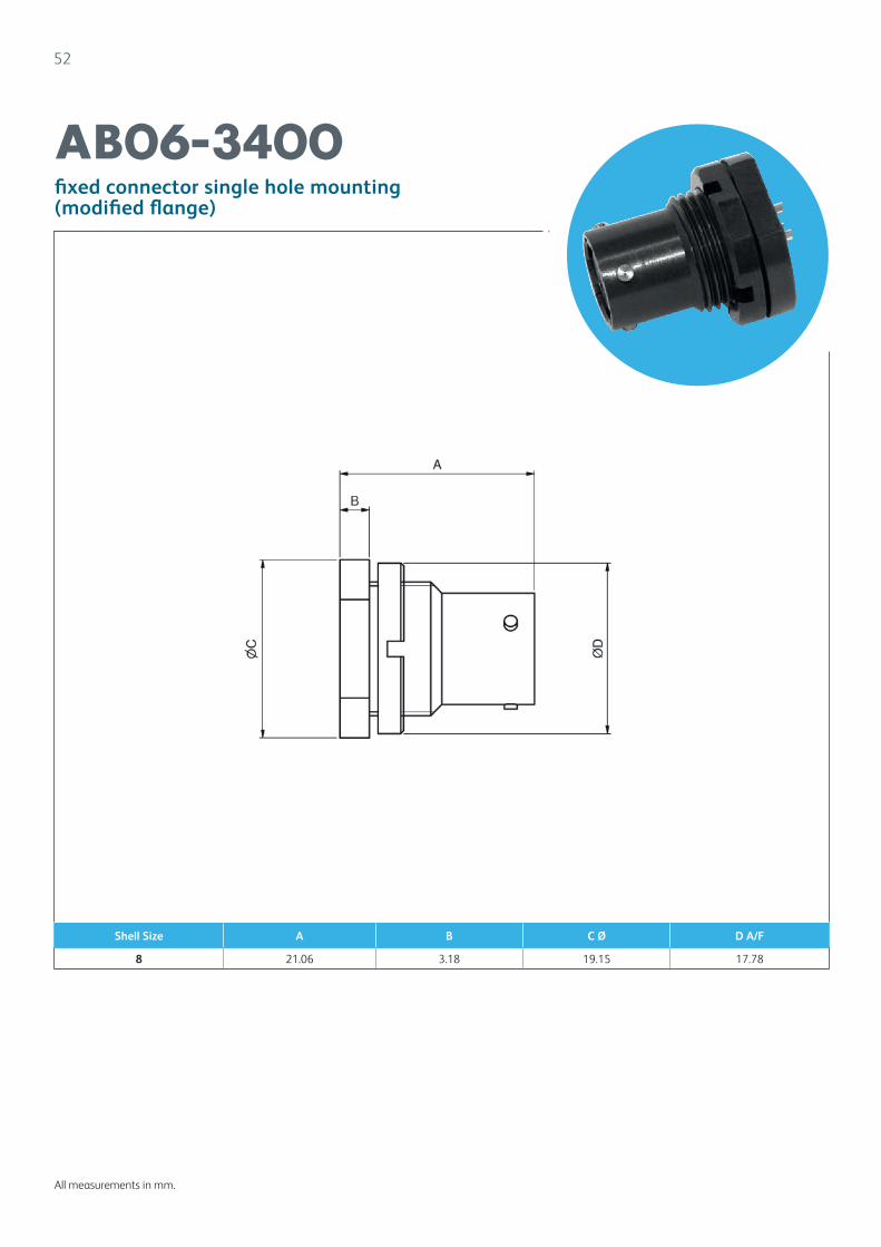
AB06 3400: fixed connector single hole mounting (modified flange) 52
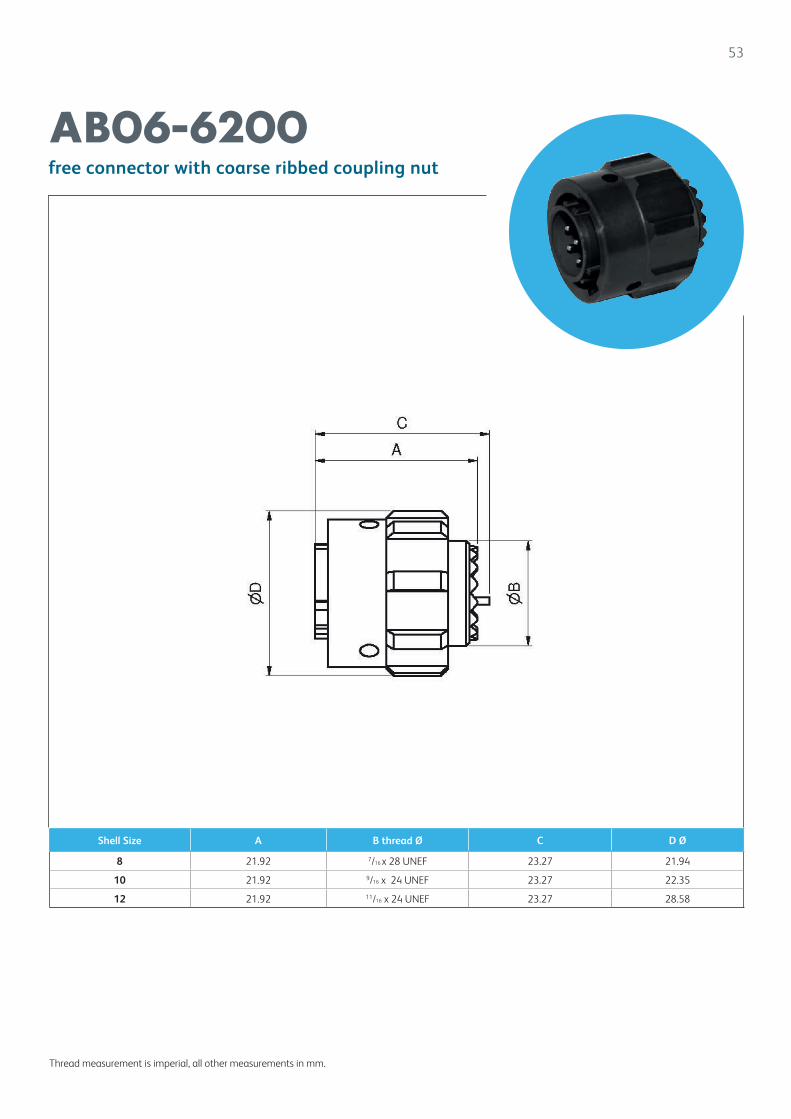
AB06 6200: free connector with coarse ribbed coupling nut 53
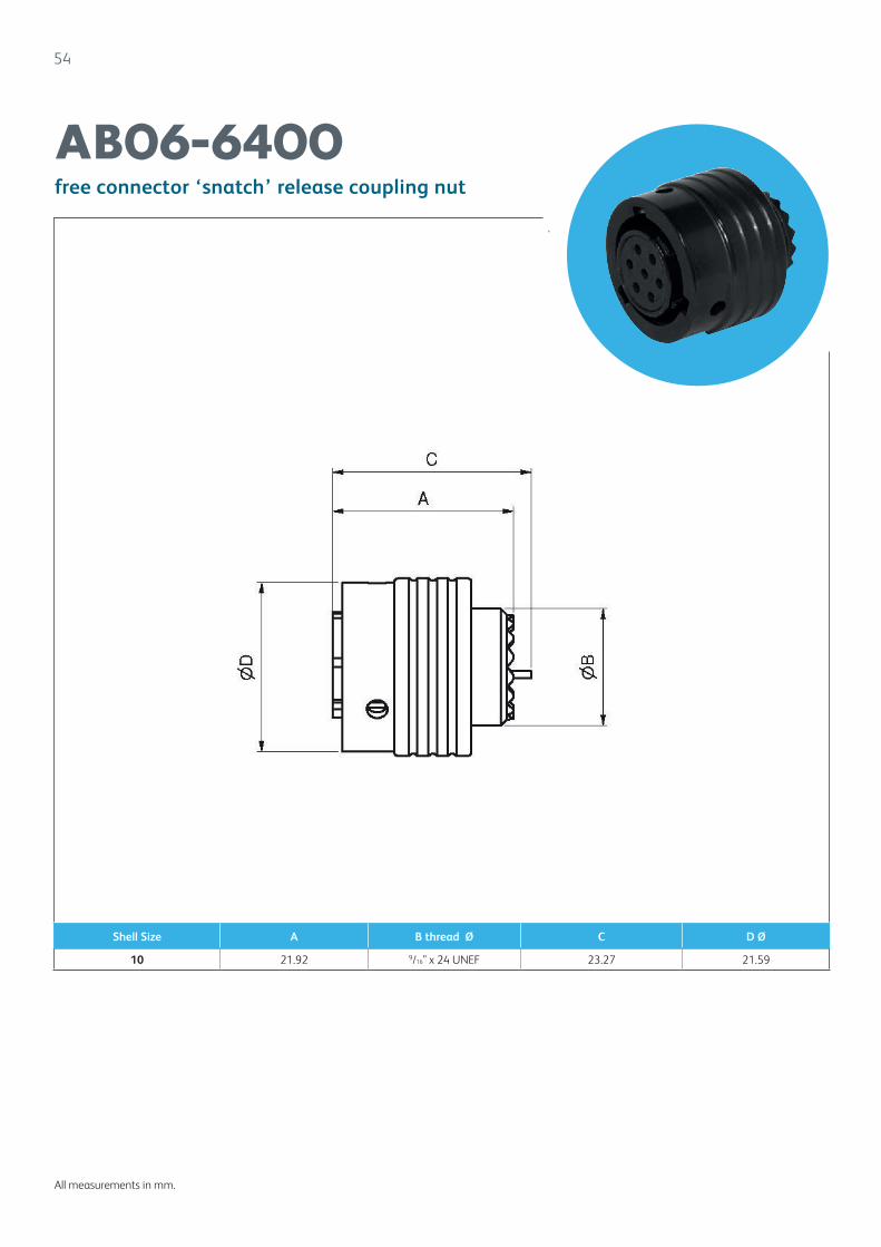
AB06 6400: free connector ‘snatch’ release coupling nut 54
Accessories
Accessories Part. No. Explanation 55
AB06 0010: 90º angled outlet 56
AB06 0011: 90º angled outlet (non-standard, #10 accepts #12 cable) 57
AB06 0020: straight outlet, large bore short boot 58
AB06 0021: straight outlet, small bore short boot 59
AB05 0022: straight outlet, small bore long boot 60
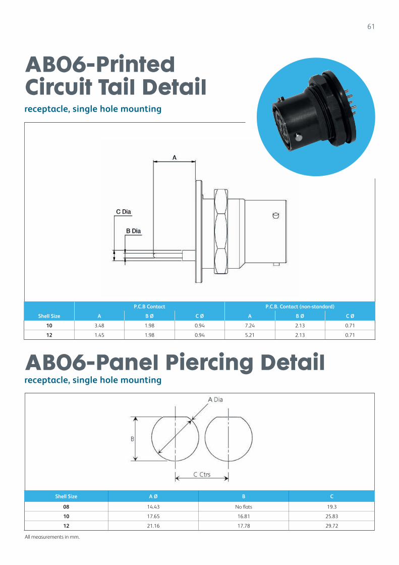
Printed Circuit Tail Detail 61
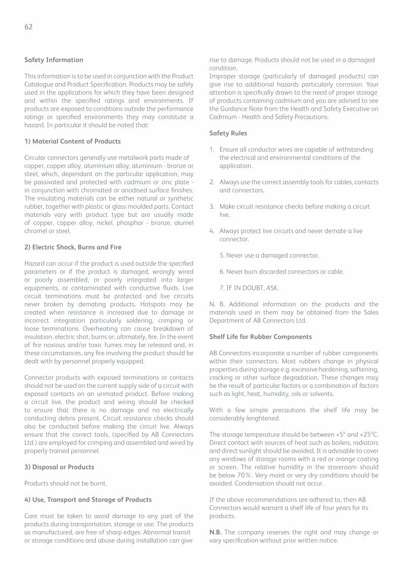
Panel Piercing Detail 61
Safety Information 62ation
45
technical information
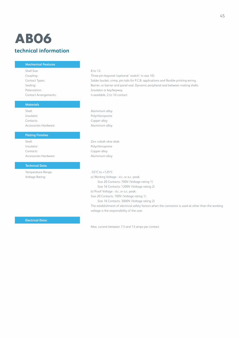
AB06
Mechanical Features
Shell Size: 8 to 12
Coupling: Three pin bayonet (optional ‘snatch’ in size 10)
Contact Types: Solder bucket, crimp, pin tails for P.C.B. applications and flexible printing wiring.
Sealing: Barrier, or barrier and panel seal. Dynamic peripheral seal between mating shells.
Polarization: Insulator or key/keyway
Contact Arrangements: 4 available, 2 to 10 contact
Materials
Shell: Aluminium alloy
Insulator: Polychloroprene
Contacts: Copper alloy
Accessories Hardware: Aluminium alloy
Plating Finishes
Shell: Zinc cobalt olive drab
Insulator: Polychloroprene
Contacts: Copper alloy
Accessories Hardware: Aluminium alloy
Technical Data
Temperature Range: -55ºC to +125ºC
Voltage Rating: a) Working Voltage - d.c. or a.c. peak:
Size 20 Contacts: 700V (Voltage rating 1)
Size 16 Contacts: 1200V (Voltage rating 2)
b) Proof Voltage - d.c. or a.c. peak:
Size 20 Contacts: 700V (Voltage rating 1)
Size 16 Contacts: 3000V (Voltage rating 2)
The establishment of electrical safety factors when the connector is used at other than the working
voltage is the responsibility of the user.
Electrical Data:
Max. current between 7.5 and 13 amps per contact
46
part number explanation
AB06
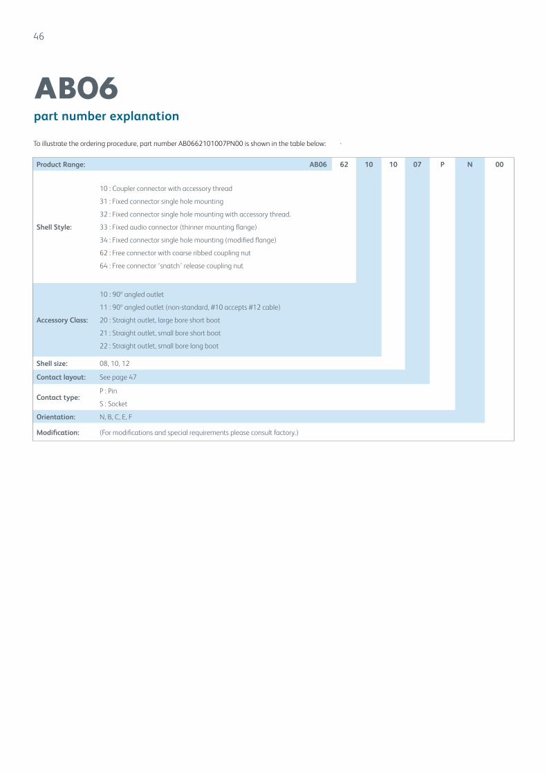
To illustrate the ordering procedure, part number AB0662101007PN00 is shown in the table below:
Product Range: AB06 62 10 10 07 P N 00
Shell Style:
10 : Coupler connector with accessory thread
31 : Fixed connector single hole mounting
32 : Fixed connector single hole mounting with accessory thread.
33 : Fixed audio connector (thinner mounting flange)
34 : Fixed connector single hole mounting (modified flange)
62 : Free connector with coarse ribbed coupling nut
64 : Free connector ‘snatch’ release coupling nut
Accessory Class:
10 : 90º angled outlet
11 : 90º angled outlet (non-standard, #10 accepts #12 cable)
20 : Straight outlet, large bore short boot
21 : Straight outlet, small bore short boot
22 : Straight outlet, small bore long boot
Shell size: 08, 10, 12
Contact layout: See page 47
Contact type:P : Pin
S : Socket
Orientation: N, B, C, E, F
Modification: (For modifications and special requirements please consult factory.)
47
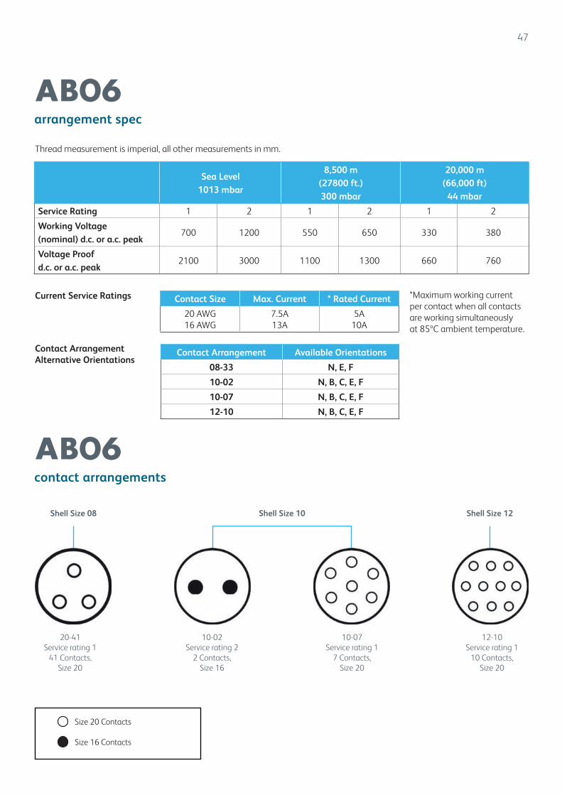
arrangement spec
contact arrangements
AB06
AB06
Sea Level 1013 mbar
8,500 m (27800 ft.) 300 mbar
20,000 m (66,000 ft)
44 mbar
Service Rating 1 2 1 2 1 2
Working Voltage (nominal) d.c. or a.c. peak
700 1200 550 650 330 380
Voltage Proof d.c. or a.c. peak
2100 3000 1100 1300 660 760
Contact Size Max. Current * Rated Current
20 AWG16 AWG
7.5A13A
5A10A
Contact Arrangement Available Orientations
08-33 N, E, F
10-02 N, B, C, E, F
10-07 N, B, C, E, F
12-10 N, B, C, E, F
Thread measurement is imperial, all other measurements in mm.
*Maximum working currentper contact when all contactsare working simultaneouslyat 85ºC ambient temperature.
Current Service Ratings
Contact ArrangementAlternative Orientations
Shell Size 08 Shell Size 12Shell Size 10
20-41Service rating 1
41 Contacts, Size 20
10-02Service rating 2
2 Contacts,Size 16
10-07Service rating 1
7 Contacts,Size 20
12-10Service rating 1
10 Contacts,Size 20
Size 20 Contacts
Size 16 Contacts

48
coupler connector with accessory thread
AB06-1000
Shell Size A B C thread UNEF 2A
D Ø
10 22.96 2.49 9/16 -24 24.00
12 22.96 2.49 11/16 -24 26.42
Thread measurement is imperial, all other measurements in mm.
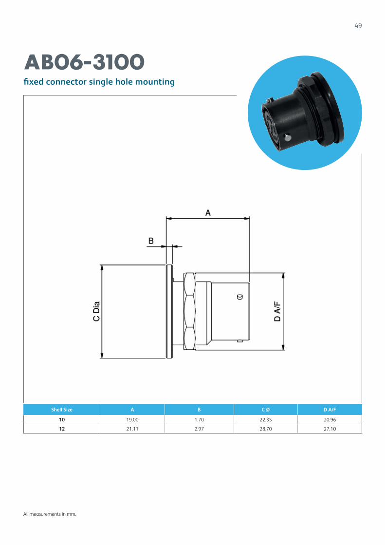
49
fixed connector single hole mounting
AB06-3100
Shell Size A B C Ø D A/F
10 19.00 1.70 22.35 20.96
12 21.11 2.97 28.70 27.10
All measurements in mm.
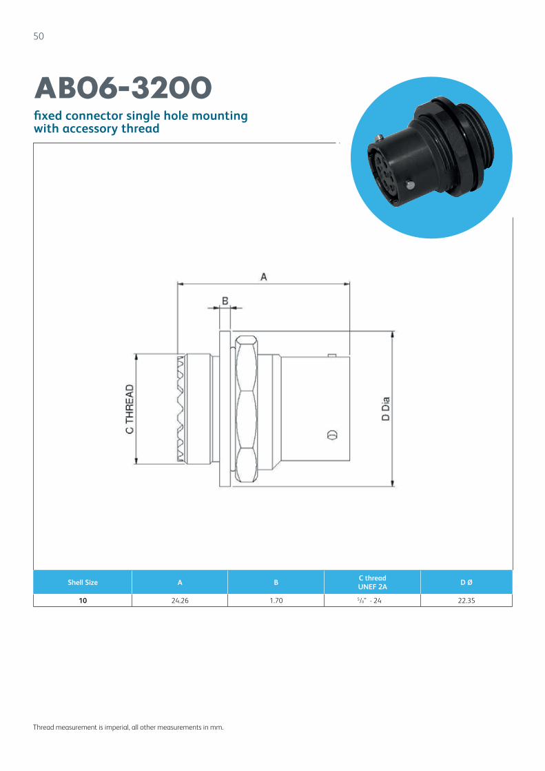
50
fixed connector single hole mountingwith accessory thread
AB06-3200
Shell Size A BC threadUNEF 2A
D Ø
10 24.26 1.70 5/8” - 24 22.35
Thread measurement is imperial, all other measurements in mm.
51
fixed audio connector (thinner mounting flange)
AB06-3300
All measurements in mm.
Shell Size A B C Ø D A/F
10 18.92 0.66 22.35 20.96
52
fixed connector single hole mounting(modified flange)
AB06-3400
All measurements in mm.
Shell Size A B C Ø D A/F
8 21.06 3.18 19.15 17.78
53
free connector with coarse ribbed coupling nut
AB06-6200
Thread measurement is imperial, all other measurements in mm.
Shell Size A B thread Ø C D Ø
8 21.92 7/16 x 28 UNEF 23.27 21.94
10 21.92 9/16 x 24 UNEF 23.27 22.35
12 21.92 11/16 x 24 UNEF 23.27 28.58
54
free connector ‘snatch’ release coupling nut
AB06-6400
All measurements in mm.
Shell Size A B thread Ø C D Ø
10 21.92 9/16” x 24 UNEF 23.27 21.59
55
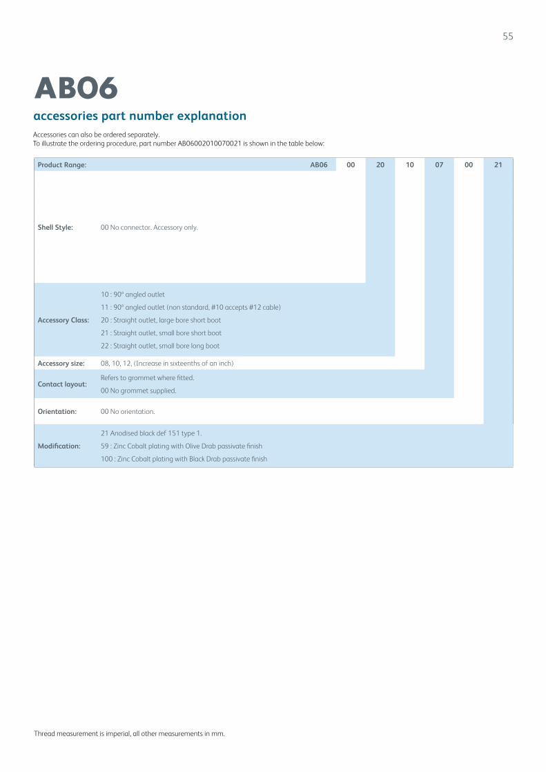
accessories part number explanation
AB06
Thread measurement is imperial, all other measurements in mm.
Product Range: AB06 00 20 10 07 00 21
Shell Style: 00 No connector. Accessory only.
Accessory Class:
10 : 90º angled outlet
11 : 90º angled outlet (non standard, #10 accepts #12 cable)
20 : Straight outlet, large bore short boot
21 : Straight outlet, small bore short boot
22 : Straight outlet, small bore long boot
Accessory size: 08, 10, 12, (Increase in sixteenths of an inch)
Contact layout:Refers to grommet where fitted.
00 No grommet supplied.
Orientation: 00 No orientation.
Modification:
21 Anodised black def 151 type 1.
59 : Zinc Cobalt plating with Olive Drab passivate finish
100 : Zinc Cobalt plating with Black Drab passivate finish
Accessories can also be ordered separately.To illustrate the ordering procedure, part number AB06002010070021 is shown in the table below:
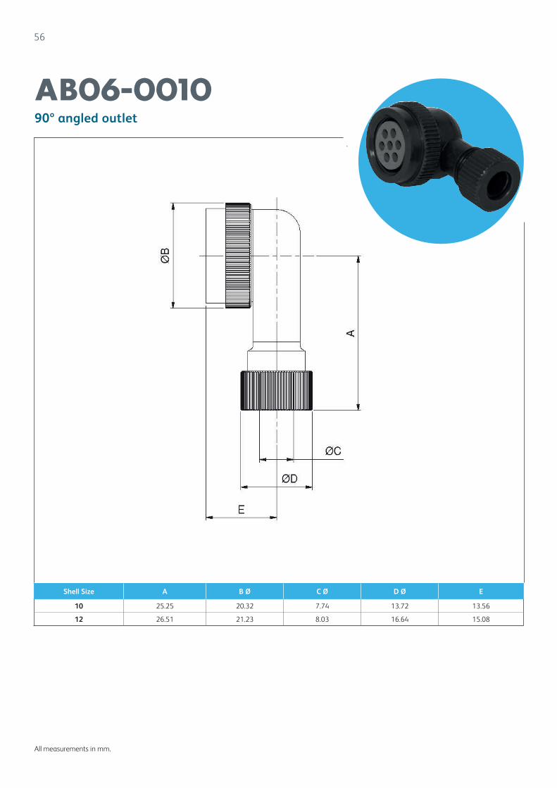
56
90º angled outlet
AB06-0010
All measurements in mm.
Shell Size A B Ø C Ø D Ø E
10 25.25 20.32 7.74 13.72 13.56
12 26.51 21.23 8.03 16.64 15.08
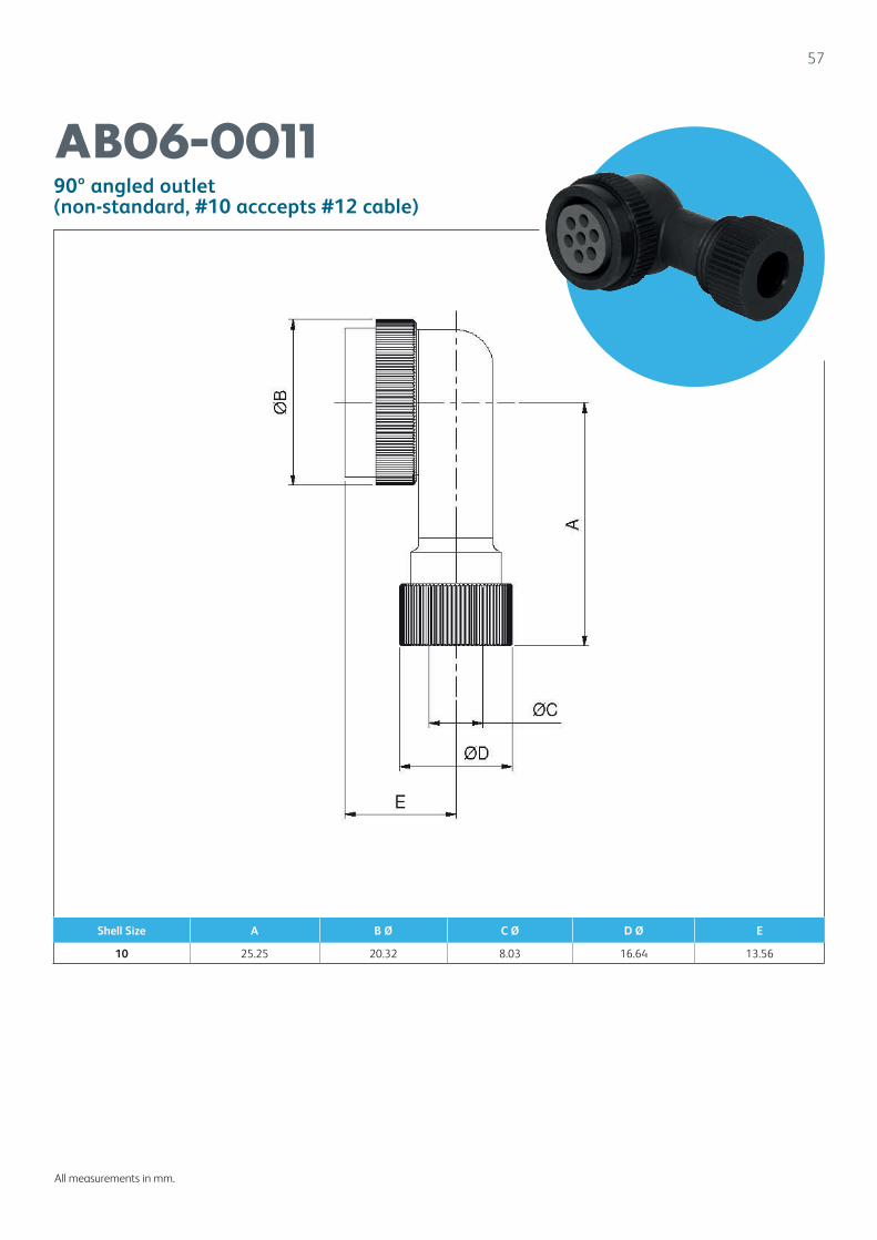
57
90º angled outlet(non-standard, #10 acccepts #12 cable)
AB06-0011
All measurements in mm.
Shell Size A B Ø C Ø D Ø E
10 25.25 20.32 8.03 16.64 13.56

58
straight outlet, large bore short boot
AB06-0020
All measurements in mm.
Shell Size A B Ø C Ø
8 34.13 7.26 15.88
10 42.25 7.26 17.70
12 42.44 7.26 21.46
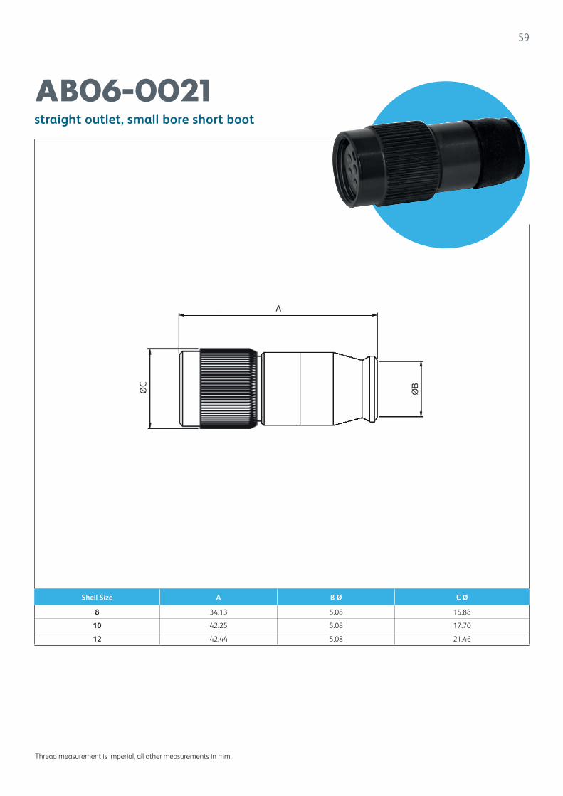
59
straight outlet, small bore short boot
AB06-0021
Thread measurement is imperial, all other measurements in mm.
Shell Size A B Ø C Ø
8 34.13 5.08 15.88
10 42.25 5.08 17.70
12 42.44 5.08 21.46

60
straight outlet, small bore long boot
AB06-0022
All measurements in mm.
Shell Size A B Ø C Ø
10 78.35 5.08 16.74
Shell Size A Ø B C
08 14.43 No flats 19.3
10 17.65 16.81 25.83
12 21.16 17.78 29.72
AB06-Printed Circuit Tail Detail
AB06-Panel Piercing Detail
61
receptacle, single hole mounting
receptacle, single hole mounting
All measurements in mm.
P.C.B Contact P.C.B. Contact (non-standard)
Shell Size A B Ø C Ø A B Ø C Ø
10 3.48 1.98 0.94 7.24 2.13 0.71
12 1.45 1.98 0.94 5.21 2.13 0.71
62
Safety Information
This information is to be used in conjunction with the Product Catalogue and Product Specification. Products may be safely used in the applications for which they have been designed and within the specified ratings and environments. If products are exposed to conditions outside the performance ratings or specified environments they may constitute a hazard. In particular it should be noted that:
1) Material Content of Products
Circular connectors generally use metalwork parts made ofcopper, copper alloy, aluminium alloy, aluminium - bronze or steel, which, dependant on the particular application, may be passivated and protected with cadmium or zinc plate - in conjunction with chromated or anodised surface finishes. The insulating materials can be either natural or synthetic rubber, together with plastic or glass moulded parts. Contact materials vary with product type but are usually made of copper, copper alloy, nickel, phosphor - bronze, alumel chromel or steel.
2) Electric Shock, Burns and Fire
Hazard can occur if the product is used outside the specified parameters or if the product is damaged, wrongly wired or poorly assembled, or poorly integrated into larger equipments, or contaminated with conductive fluids. Live circuit terminations must be protected and live circuits never broken by demating products. Hotspots may be created when resistance is increased due to damage or incorrect integration particularly soldering, crimping or loose terminations. Overheating can cause breakdown of insulation, electric shot, burns or, ultimately, fire. In the event of fire noxious and/or toxic fumes may be released and, in these circumstances, any fire involving the product should be dealt with by personnel properly equipped.
Connector products with exposed terminations or contacts should not be used on the current supply side of a circuit with exposed contacts on an unmated product. Before making a circuit live, the product and wiring should be checked to ensure that there is no damage and no electrically conducting debris present. Circuit resistance checks should also be conducted before making the circuit live. Always ensure that the correct tools, (specified by AB Connectors Ltd.) are employed for crimping and assembled and wired by properly trained personnel.
3) Disposal or Products
Products should not be burnt.
4) Use, Transport and Storage of Products
Care must be taken to avoid damage to any part of the products during transportation, storage or use. The productsas manufactured, are free of sharp edges. Abnormal transitor storage conditions and abuse during installation can give
rise to damage. Products should not be used in a damagedcondition.Improper storage (particularly of damaged products) can give rise to additional hazards particularly corrosion. Your attention is specifically drawn to the need of proper storageof products containing cadmium and you are advised to see the Guidance Note from the Health and Safety Executive on Cadmium - Health and Safety Precautions.
Safety Rules
1. Ensure all conductor wires are capable of withstanding the electrical and environmental conditions of the application.
2. Always use the correct assembly tools for cables, contacts and connectors.
3. Make circuit resistance checks before making a circuit live.
4. Always protect live circuits and never demate a live connector.
5. Never use a damaged connector.
6. Never burn discarded connectors or cable.
7. IF IN DOUBT, ASK.
N. B. Additional information on the products and the materials used in them may be obtained from the Sales Department of AB Connectors Ltd.
Shelf Life for Rubber Components
AB Connectors incorporate a number of rubber componentswithin their connectors. Most rubbers change in physical properties during storage e.g. excessive hardening, softening,cracking or other surface degradation. These changes may be the result of particular factors or a combination of factors such as light, heat, humidity, oils or solvents.
With a few simple precautions the shelf life may be considerably lenghtened.
The storage temperature should be between +5º and +25ºC.Direct contact with sources of heat such as boilers, radiatorsand direct sunlight should be avoided. It is advisable to coverany windows of storage rooms with a red or orange coating or screen. The relative humidity in the storeroom should be below 70%. Very moist or very dry conditions should be avoided. Condensation should not occur.
If the above recommendations are adhered to, then ABConnectors would warrant a shelf life of four years for itsproducts.
N.B. The company reserves the right and may change or vary specification without prior written notice.

The world’s demand for electronics is increasing as new technologies, with a higher dependence on complex components, are being adopted by a broader customer base. This growth provides TT electronics an assured future as we focus on efforts to deliver excellence in customer service and quality products to these markets. From our strong UK base, the company has achieved truly global reach. We have established technical and manufacturing facilities in strategic countries maintaining the successful formula of close liaison with our customers in all major overseas markets.
In addition, through strategic relationships with Original Equipment Manufacturers around the world, we are now in the enviable position where we gain double benefit - from growth in their markets and from the increase in the electronic content of end products.
Information on TT electronics companies can be found by contacting:-
Head Office:
TT Electronics plcFourth Floor, St Andrews HouseWest StreetWokingSurreyGU21 6EBUK
Tel: +44 (0) 1932 825300Fax: +44 (0) 1932 836450
Email: [email protected]: www.ttelectronics.com
63
Global Presence

AB Connectors
General Note TT Electronics reserves the right to make changes in product specification without notice or liability.All information is subject to TT Electronics’ own data and is considered accurate at time of going to print.
AB Connectors LimitedAbercynon,Mountain AshRhondda Cynon TaffCF45 4SF, UK.Tel: +44(0)1443 740331Fax: +44(0)1443 741676Internet:http://www.ttelectronics.com/[email protected]
© TT Electronics plc