Embed Size (px)
Citation preview

1
Presented to AASHTO T-8, June 28, 2016
AASHTO AS 13-0024Support for the HSCOBS Technical Committee on Moveable Bridges (T-8) in a Technical Advisory Role for Specification Updates – Span Lock Design Study
By James M. Phillips III, PEHardesty & Hanover, Tampa, FL
STUDY TEAM
Hardesty & Hanover, LLC• Rafal Wuttrich, PE – Lead Finite Element Modeling
AECOM (formerly URS and E.C. Driver & Associates, Inc.)• Jim Englert, PE – Project Manager• Michael Reponen – Finite Element Modeling
• FDOT• Will Potter, PE - Structures Research – Field Instrumentation and Testing

AGENDA
Review Purpose of Study Study Limitations Sunrise Blvd. Field Tests Summarize Key Findings Present Recommendations

PURPOSE OF STUDY
4
Advance knowledge of span lock behavior Provide recommendations to T-8 Improve the general practice of span lock design Improve AASHTO LRFD Movable Highway Bridge
Design Specifications Determine appropriate impact factors Quantify the effects of operating clearances and
wear Quantify the effects of bascule span deflection Identify alternative materials
Photo 3 & 4 – Span Lock Housing (Left) and Bushing (Right) exhibiting severe wear of the turned bolt holes. Cortez Bridge, Manatee County, FL, FDOT District One; (December 2014, Hardesty & Hanover, LLC)

SCOPE LIMITATIONS
Double-Leaf Trunnion Bascule Bridge
Lock Bar Type Span Locks
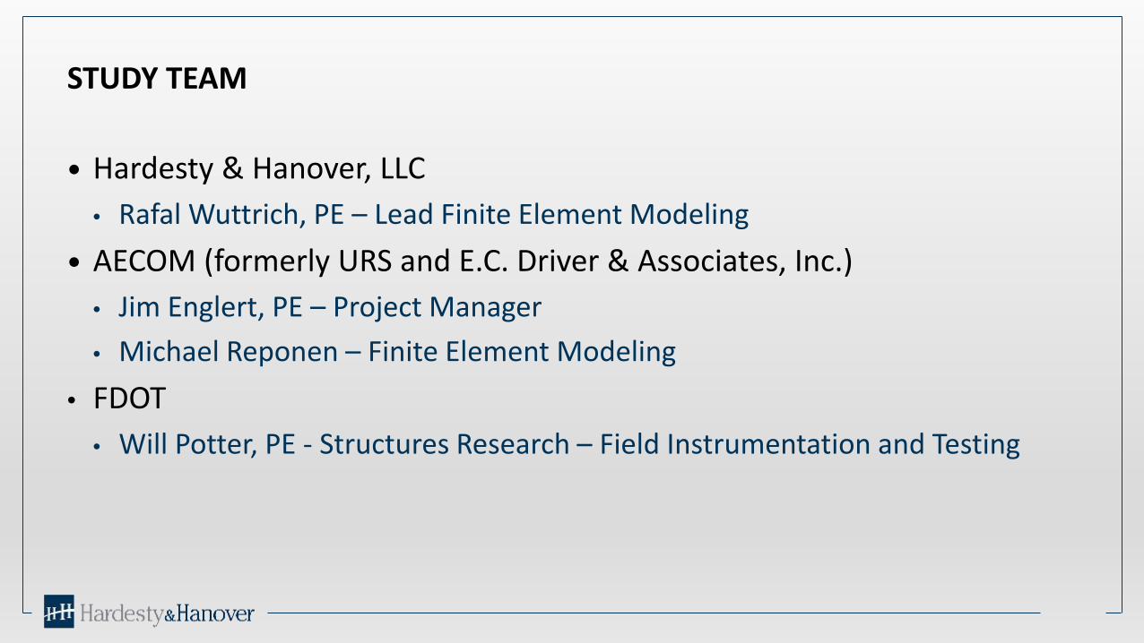
SUNRISE BLVD. FIELD INSTRUMENTATION AND LOAD TESTING – 4/29/15
6
Strain Gauges: Outside Girder Span Lock; Outside Main Girders Tip Rotation via Displacement Transducers Variable Shimming of Live Load Shoe
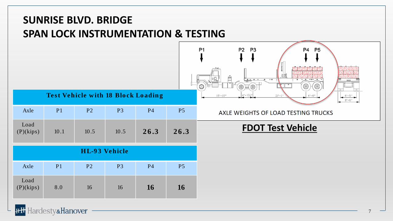
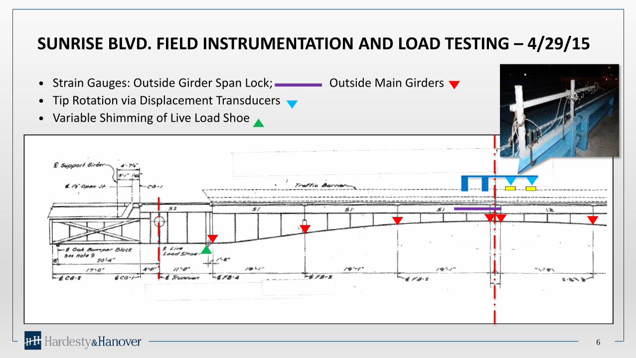
SUNRISE BLVD. BRIDGESPAN LOCK INSTRUMENTATION & TESTING
7
FDOT Test Vehicle
Test Vehicle with 18 Block Loading
Axle P1 P2 P3 P4 P5
Load (P)(kips) 10.1 10.5 10.5 26.3 26.3
HL-93 Vehicle
Axle P1 P2 P3 P4 P5
Load (P)(kips) 8.0 16 16 16 16

SUNRISE BLVD.
8
Sunrise Blvd. Bridge30 MPH Test Outside Lane
18 Block Load

9
Sunrise Blvd. Bridge30 MPH Test
Inside Lane 18 Block Load

SUNRISE BLVD. BRIDGE – CONSISTENCY OF FIELD TESTS
10
-100
-80
-60
-40
-20
0
20
40
60
80
100
1 49 97 145
193
241
289
337
385
433
481
529
577
625
673
721
769
817
865
913
961
1009
1057
1105
1153
1201
1249
1297
1345
1393
1441
1489
1537
1585
1633
1681
1729
1777
1825
1873
1921
1969
2017
2065
2113
2161
2209
2257
2305
2353
2401
2449
2497
2545
2593
2641
2689
2737
2785
2833
2881
2929
2977
3025
3073
Mic
rost
rain
Time Interval
Chart E30mph Runs in Outside Lane
Comparison of Strain in Lock Bar for 4 Tests Sunrise Blvd. Bridge Load Tests
18O301 S9 18O302 S9 18O303 S9 18O304 S9

KEY FINDINGS OF PROJECT
11
Dynamic effects are significant The Shape of Wear Plates and Load Shoes affects contact stresses Secondary effects of deformations can be significant – especially
on the Forward Guides and Receivers Wear of lock components results in a general reduction in Lock
Effectiveness Improper Adjustment of Live Load Shoes (aka Live Load Bearings)
can have a measurable effect on Span Lock and Main Girder strains

DYNAMIC EFFECTS
AASHTO Table 3.6.2.1-1, Dynamic Load Allowance, IM
Components IM
Deck Joints – All Limit States 75%
All Other Components
Fatigue and Fracture Limit State
All Other Limit States
15%
33%
Article 2.4.1.2.4, End Floorbeams, of AASHTO Movable states:
“The end floorbeams of the moving span shall be proportioned for full factored live load plus twice the normal dynamic load allowance specified in Article 3.6.2 of the AASHTO LRFD Bridge Design Specifications.”
Article 6.8.1.5.1, Locking Devices, of AASHTO Movable states:
“Double leaf spans shall be provided with center locks to lock together the toe ends of the spans and tail locks or latches. Center locks shall transfer live load and impact from on leaf to the other.”
AASHTO Dynamic Load Allowance, IM

DYNAMIC EFFECTS
Dynamic Effect Calculated as Ratio of Measured Range of Strain for 30 MPH Truck / Slow Rolling Truck
The Dynamic Effect was consistently larger as the truck was moved away from the strain gauge of interest
Lock Bar Strains:• Dynamic Effect in the range of 1.17 to 1.58 for loading in the lane adjacent to the lock bar• Dynamic Effect in the range of 2.17 to 4.43 for loading in the lane opposite the lock bar
• Forward Guide and Receiver Strains:• Dynamic Effect in the range of 1.05 to 2.15 for loading in the lane adjacent to the lock bar• Dynamic Effect in the range of 1.49 to 4.25 for loading in the lane opposite the lock bar• The largest ratios were recorded in the forward guides on the side facing the center joint

HILLSBOROUGH AVE BRIDGESPAN LOCK INSTRUMENTATION & TESTING
14
Lock Bar Strain - Static vs Dynamic Loading, Heavy Test Truck (37.5k Axle) Static is Slow Roll Across Span Dynamic is 30 MPH Across Span
Peak Strain Static vs Dynamic Comparison at Top of Lock Bar
Gauge Location Peak Static Strain
Peak Dynamic Strain
RatioDynamic/Static
Tension 108 117 1.08
Compression 209 325 1.55
Range 317 442 1.39N-1 is Located on Top of Lock Bar

HILLSBOROUGH AVE BRIDGESPAN LOCK INSTRUMENTATION & TESTING
15
-200
-150
-100
-50
0
50
100
150
200
160 11
917
823
729
635
541
447
353
259
165
070
976
882
788
694
510
0410
6311
2211
8112
4012
9913
5814
1714
7615
3515
9416
5317
1217
7118
3018
8919
4820
0720
6621
2521
8422
4323
0223
6124
2024
7925
3825
9726
5627
1527
7428
3328
92
Test 2 (Slow Roll) vs Test 5 (30 MPH)North Lock Bar Strain
18 Block Load, Outside Lane
N-1 T5 N-2 T5 N-1 T2 N-2 T2
Peak Strain Static vs Dynamic Comparison at Top of Lock Bar
Gauge Location
Peak Static Strain (T/C)
Peak Dynamic Strain
RatioDynamic/Static
N-1 Peak 143/75 170/113 1.18/1.51
N-1 Range 218 283 1.30
N-2 Peak 76/150 116/175 1.53/1.17
N-2 Range 226 291 1.29
Comparison of Strains in the Adjacent Lock Bar
Max. Stress Range = 8.4 ksi
N-1 is Located on Top of Lock Bar N-2 is Located on Bottom of Lock Bar
-150
-100
-50
0
50
100
150
Mic
roSt
rain
Time Interval
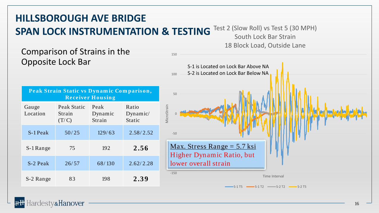
Test 2 (Slow Roll) vs Test 5 (30 MPH)South Lock Bar Strain
18 Block Load, Outside Lane
S-1 T5 S-1 T2 S-2 T2 S-2 T5
HILLSBOROUGH AVE BRIDGESPAN LOCK INSTRUMENTATION & TESTING
16
Peak Strain Static vs Dynamic Comparison, Receiver Housing
Gauge Location
Peak Static Strain (T/C)
Peak Dynamic Strain
RatioDynamic/ Static
S-1 Peak 50/25 129/63 2.58/2.52
S-1 Range 75 192 2.56
S-2 Peak 26/57 68/130 2.62/2.28
S-2 Range 83 198 2.39
Comparison of Strains in the Opposite Lock Bar
Max. Stress Range = 5.7 ksiHigher Dynamic Ratio, but lower overall strain
S-1 is Located on Lock Bar Above NA S-2 is Located on Lock Bar Below NA
HILLSBOROUGH AVE BRIDGESPAN LOCK INSTRUMENTATION & TESTING
17
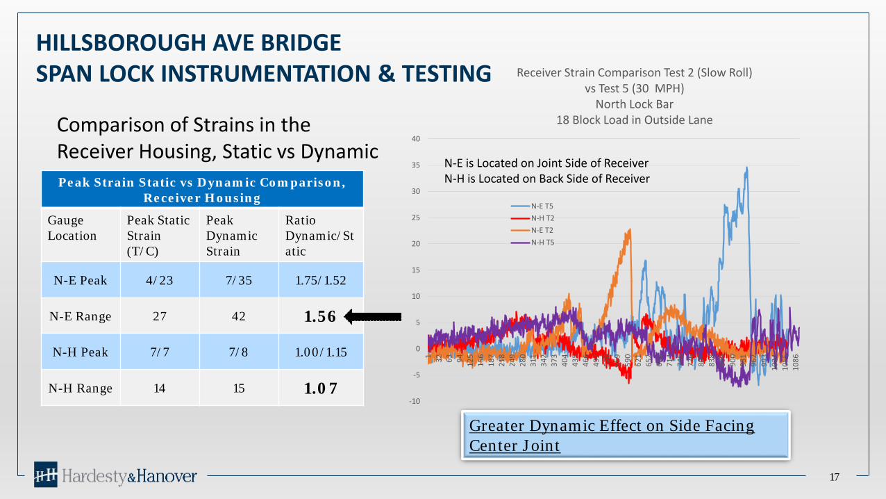
Comparison of Strains in the Receiver Housing, Static vs DynamicPeak Strain Static vs Dynamic Comparison,
Receiver Housing
Gauge Location
Peak Static Strain (T/C)
Peak Dynamic Strain
RatioDynamic/Static
N-E Peak 4/23 7/35 1.75/1.52
N-E Range 27 42 1.56
N-H Peak 7/7 7/8 1.00/1.15
N-H Range 14 15 1.07-10
-5
0
5
10
15
20
25
30
35
40
1 32 63 94 125
156
187
218
249
280
311
342
373
404
435
466
497
528
559
590
621
652
683
714
745
776
807
838
869
900
931
962
993
1024
1055
1086
Receiver Strain Comparison Test 2 (Slow Roll)vs Test 5 (30 MPH)
North Lock Bar18 Block Load in Outside Lane
N-E T5N-H T2N-E T2N-H T5
Greater Dynamic Effect on Side Facing Center Joint
N-E is Located on Joint Side of ReceiverN-H is Located on Back Side of Receiver

HILLSBOROUGH AVE BRIDGESPAN LOCK INSTRUMENTATION & TESTING
18
Comparison of Strains in the Forward Guide Housing, Static vs Dynamic
Peak Strain Static vs Dynamic Comparison, Receiver Housing
Gauge Location
Peak Static Strain (T/C)
Peak Dynamic
Strain
Ratio Dynamic/
Static
N-C Peak 7/38 7/59 1.00/1.55
N-C Range 45 66 1.47
N-D Peak 4/18 3/31 0.75/1.72
N-D Range 22 34 1.55-20
-10
0
10
20
30
40
50
60
70
1 26 51 76 101
126
151
176
201
226
251
276
301
326
351
376
401
426
451
476
501
526
551
576
601
626
651
676
701
726
751
776
801
826
851
876
901
926
951
976
1001
1026
1051
1076
Guide Strain Comparison Test 2 (Slow Roll) vs Test 5 (30 MPH)North Lock Bar
18 Block Load in Outside Lane
N-C T5 N-D T5 N-C T2 N-D T2
N-C and N-D are Located on Joint Side of Forward Guide

LOAD SHOE / WEAR PLATE SHAPE
19
Contact Stresses at the Lock Bar interface with the Wear Plates or Load Shoes are influenced by the Geometry and System Deformations
System DeformationsLock Bar Contact Stress
Load Shoe Contact Stress

LOAD SHOE / WEAR PLATE SHAPE
20
Studied shapes of load shoes, from left: flat shape with radius on leading edge, round shape w/ large radius, compound shape (receiver shoe shown)
Figure 8a - Contact Stress on load shoes: flat shape with radius on leading edge
Figure 8b - Contact Stress on load shoes; round shape w/ large radius
Figure 8c - Contact Stress on load shoes; compound shape
72” Radius Effective In Reducing Edge Loading

STRUCTURAL DEFORMATIONS - GIRDER ROTATION AT THE SPAN LOCKS
21
Sunrise Bridge Tests Included Measurement of End Rotations (Relative Slope Between Leaves)
For the Test Load in the Lane Adjacent to the Instrumented Lock/Girder Relative End Rotation Measured 0.0047 in/in for Static Loading and 0.0053 to 0.0080 in/in for Dynamic Loading
The Calculated Equivalent Slope at a Center Joint for:• Deflection of L/800 = 0.008 in/in• Deflection of L/1000 = 0.006 in/in
Relative Slope
L
Δ

STRUCTURAL DEFORMATIONS - GIRDER ROTATION AT THE SPAN LOCKS
22
Table 3 – Summary of Rotation at Center JointSunrise Blvd. Bridge Load Tests
Test Static/Dynamic Load Position Load Shoe Condition Slope18OSR1 Static Outside Lane Tight Contact all four LLS 4.718OSR2 Static Outside Lane Tight Contact all four LLS 4.718OSR3S Static Outside Lane 0.040” Shim NE LLS, 0.015” gap under SE LLS 4.518OSR4S Static Outside Lane 0.040” Shim SE LLS, 0.015” gap under NE LLS 5.018O301 Dynamic Outside Lane Tight Contact all four LLS 5.318O302 Dynamic Outside Lane Tight Contact all four LLS 6.618O303 Dynamic Outside Lane Tight Contact all four LLS 8.018O304 Dynamic Outside Lane Tight Contact all four LLS 6.118O305S Dynamic Outside Lane 0.040” Shim NE LLS, 0.015” gap under SE LLS 6.318O306S Dynamic Outside Lane 0.040” Shim SE LLS, 0.015” gap under NE LLS 6.3

STRUCTURAL DEFORMATIONS – ECCENTRIC LOADING
23
Table 5 – Comparison of Guide and Receiver StrainsSunrise Blvd. Bridge Load Tests
Load Position
Forward Guide Receiver
Top Gauges Bott. Gauges Top Gauges Bott. Gauges
Back Side
Jt. SideBack Side
Jt. Side Jt. SideBack Side
Jt. SideBack Side
Outside Lane
43 187 47 188 64 44 48 44
Middle Lane
36 123 36 130 39 54 44 31
Inside Lane
28 69 28 82 19 31 26 20

RECOMMENDED CHANGES TO AASHTO LRDF MOVABLE
Recommendation No. 1: Make revisions to supplement the AASHTO Movable code to make explicit the dynamic allowance to apply in design of span locks. Expand AASHTO Movable, Article 2.4.1.2, Dynamic Load Allowance, to add the following:
“2.4.1.2.5 Span Locks
The span locks of double-leaf bascule bridges (center locks) shall be proportioned for full live load plus twice the normal live load dynamic load allowance, specified in Article 3.6.2 of the AASHTO LRFD Bridge Design Specifications.”
To further clarify the application of this provision to the fatigue limit state, add the following commentary:
“C2.4.1.2.5
Applying twice the normal live load dynamic allowance applies to use of the IM values for Strength, Service and Fatigue Limit States.”

RECOMMENDED CHANGES TO AASHTO, CONTINUED
Recommendation No. 2: Make explicit the requirements for the primary load transfer elements of span locks subject to contact stress, including guide and receiver bushings of lock bar type systems and shoes or wear plates of jaw and diaphragm or other lock systems to have a shape that relieves edge loading due to rotations and deformations of the supporting structural system. This could be accomplished by adding the following to Article 6.8.1.5.1, Locking Devices of the AASHTO Movable as follows:
“Contact surfaces for span locks shall be designed and detailed to minimize edge loading that may occur due to the deformation of the supporting structure under vehicular loading. Provide a minimum ½” radius on the leading and trailing edges of contact surfaces subject to edge loading. Providing a radius on one of the contact surfaces should be considered where other means are not available to relieve edge loading.”

RECOMMENDED CHANGES TO AASHTO, CONTINUEDRecommendation No. 3: Add commentary to address the rotations and deformations that should be considered. This could be accomplished by adding the following commentary:
“C6.8.1.5
Contact surfaces for span lock systems include wear plates or bushings in the guides and receivers of lock bar type span locks, jaw and diaphragm castings, forgings or shoes, and similar components that function to transfer the load across a joint through a contact stress. Under the influence of live load, movable spans deflect and the end(s) of the span(s) at the location of locking devices rotates. For double-leaf bascule bridges the end rotations of adjacent leaves are additive in relative effect and therefore more significant than for single-leaf bascule bridges. If the lock system is attached eccentrically to the main longitudinal members, such as on a cantilevered bracket, additional torsional deflection or rotation could take place. If these deformations are not accounted for, edge loading and eccentric loading of the lock system and supports will result in significant restraint and corresponding structural effects.

RECOMMENDED CHANGES TO AASHTO, CONTINUEDRecommendation No. 3 Continued:
Typical clearances provided between lock components (e.g. lock bar and receiver bushing) may be considered in determining the magnitude and effect of edge loading. Bushings supported on multiple springs that allow the bushing to rotate with the contacting surface, may provide relief from edge loading. A radius on the contact surfaces is an effective means of accommodating movable span deformation and alleviating undesirable restraint in the span lock system. Past experienced has shown that providing wear plates or bushings with a radius of 72 inches or smaller across the contact surface provides relief from edge loading of typical deck girder double-leaf bascule spans. A larger radius may be adequate for stiff bridges, such as those with truss members or single-leaf spans with smaller end rotations. Use of a radius results in line contact which must be considered in selecting the lock bar and wear plate materials.
Additional consideration and analysis may be warranted if a double-leaf bascule is expected to carry rail traffic as the tolerances for rail alignment may be more stringent than that required for highway or pedestrian traffic.”

Questions?or More?
28

KEY FINDINGS OF PROJECT
29
Dynamic effects are significant The Shape of Wear Plates and Load Shoes affects contact stresses Secondary effects of deformations can be significant – especially on
the Forward Guides and Receivers Wear of lock components results in a general reduction in Lock
Effectiveness:• Measurable increases in differential deflection• Measurable but relatively small changes in strain
Improper Adjustment of Live Load Shoes (aka Live Load Bearings) can have a measurable effect on Span Lock and Main Girder strains

30
Hillsborough Avenue Bridge30 MPH Test, Outside Lane, 30 Block Load

WEAR EFFECTS ON LOAD TRANSFER
31
Simulated Wear Results: Measurable Decrease
in Effectiveness of the Locks
Relatively Small Decrease in Lock Bar Strain for Typical Wear (8 to 9%)
Up to 25% Decrease in Lock Bar Strain for Excessive Wear
Significant Increase in Differential Deflection
-350
-300
-250
-200
-150
-100
-50
0
50
100
150
1 38 75 112
149
186
223
260
297
334
371
408
445
482
519
556
593
630
667
704
741
778
815
852
889
926
963
1000
1037
1074
1111
1148
1185
1222
1259
1296
1333
1370
1407
1444
1481
Stra
in in
Mic
roSt
rain
/ De
flect
ion
inch
x 1
000
Time Interval
Chart GComparison of Strain & Differential Deflection For Varying Forward
Guide Clearances at North Lock Bar30 Block Load, Slow Rolling / Hillsborough Ave. Bridge
Strain No Adjust Strain 0.042 Shim Strain 0.130 Shim
Defl No Shim Defl 0.042 Shim Defl 0.140 Shim

WEAR EFFECTS ON LOAD TRANSFER
32
Table 8 – Comparison of Maximum Strain Range in the Lock Bar with Shim RemovalHillsborough Ave. Load Tests
(30 Block Truck Load for All Cases)
Lock / Load Location
Clearance at Top Shoe of Forward Guide of North Lock
0.011” 0.052” 0.140”
StrainDynamic
RatioStrain
Dynamic Ratio
StrainDynamic
Ratio
North Lock / North Lane 429 1.41 383 1.37 334 1.32
South Lock / North Lane 285 2.61 274 2.54 250 2.36
North Lock / South Lane 272 3.24 328 4.90 253 3.95
South Lock / South Lane 443 1.39 458 1.40 449 1.42

HILLSBOROUGH AVE BRIDGESPAN LOCK INSTRUMENTATION & TESTING
33
-60.000
-50.000
-40.000
-30.000
-20.000
-10.000
0.000
10.000
20.000
30.000
40.000
1 54 107
160
213
266
319
372
425
478
531
584
637
690
743
796
849
902
955
1008
1061
1114
1167
1220
1273
1326
1379
1432
1485
1538
1591
1644
Mic
rost
rain
Time Interval
North Bar StrainVariable Shim of top of North Forward Guide
30 Block Load Applied in Inside Lane
N-1 No Adjust N-1 w/0.042" N-1 w/0.130"-250
-200
-150
-100
-50
0
50
100
150
1 47 93 139
185
231
277
323
369
415
461
507
553
599
645
691
737
783
829
875
921
967
1013
1059
1105
1151
1197
1243
1289
1335
1381
1427
1473
1519
1565
1611
1657
Mic
rost
rain
Time Interval
South Bar StrainVariable Shim of top of North Forward Guide
30 Block Load Applied in Inside lane
S-1 No Adjust S-1 w/0.042" S-1 w/0.130"
Comparison of Strains in the N&S Lock Bars For Various North Lock Receiver Shim Adjustments
Poorly Shimmed Lock resulted in a measurable (8-9%) but relatively small
reduction Strain in Lock Bar

EFFECT OF LIVE LOAD SHOE SHIMMING
34
Improper Adjustment or Wear of Live Load Shoe Simulated by Inserting a 0.040” Shim Under NE Load Shoe
Table 6 – Comparison of Maximum Range of Strain for Various Live Load Shoe Shim Adjustments
Sunrise Blvd. Bridge Tests
Load Type
Load Position
LLS Condition+(Shim) -(Gap)
Inch x 10-3
MicroStrainNorth East Girder Live Load Shoe
Lock Bar @ Center Joint
North West Girder Live Load Shoe
NE SETop of
BarBott. of
Bar
StaticOutside
Lane0 0 119 109 98 138
StaticOutside
Lane+40 -15 129 113 103 134
DynamicOutside
Lane0 0 169 137 123 183
DynamicOutside
Lane+40 -15 201 145 128 213
StaticMiddle
Lane0 0 70 65 59 87
StaticMiddle
Lane+40 -15 81 69 67 83
DynamicMiddle
Lane0 0 136 102 90 166
DynamicMiddle
Lane+40 -15 153 104 93 167
StaticInside Lane
0 0 30 25 22 38
StaticInside Lane
+40 -15 34 24 23 33
DynamicInside Lane
0 0 67 63 56 74
DynamicInside Lane
+40 -15 69 66 60 66
NE NW
SWSE
0.040” Shim
0.015” Gap
Instrumented Span Lock
Inside Lane
Outside Lane
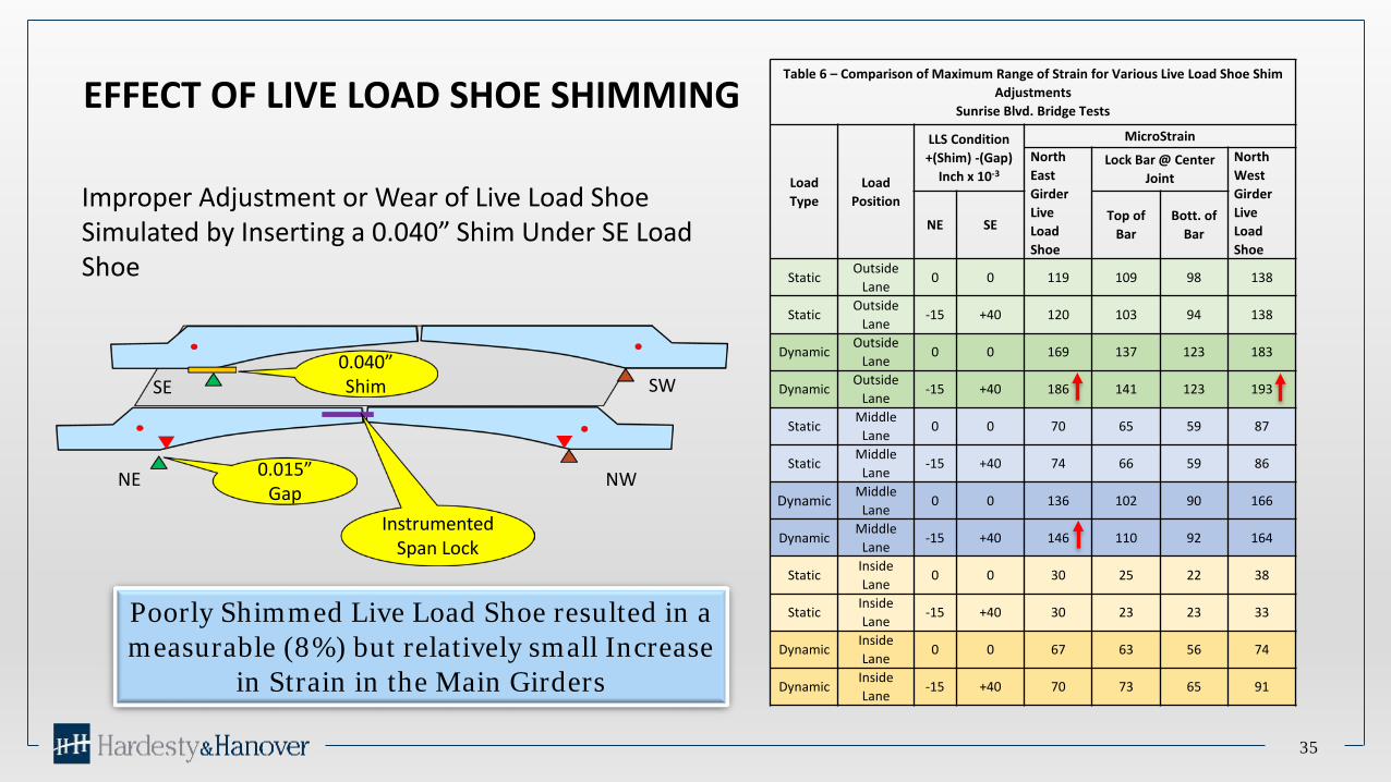
EFFECT OF LIVE LOAD SHOE SHIMMING
35
Improper Adjustment or Wear of Live Load Shoe Simulated by Inserting a 0.040” Shim Under SE Load Shoe
Table 6 – Comparison of Maximum Range of Strain for Various Live Load Shoe Shim Adjustments
Sunrise Blvd. Bridge Tests
Load Type
Load Position
LLS Condition+(Shim) -(Gap)
Inch x 10-3
MicroStrainNorth East Girder Live Load Shoe
Lock Bar @ Center Joint
North West Girder Live Load Shoe
NE SETop of
BarBott. of
Bar
StaticOutside
Lane0 0 119 109 98 138
StaticOutside
Lane-15 +40 120 103 94 138
DynamicOutside
Lane0 0 169 137 123 183
DynamicOutside
Lane-15 +40 186 141 123 193
StaticMiddle
Lane0 0 70 65 59 87
StaticMiddle
Lane-15 +40 74 66 59 86
Dynamic Middle Lane
0 0 136 102 90 166
DynamicMiddle
Lane-15 +40 146 110 92 164
StaticInside Lane
0 0 30 25 22 38
StaticInside Lane
-15 +40 30 23 23 33
DynamicInside Lane
0 0 67 63 56 74
DynamicInside Lane
-15 +40 70 73 65 91
NE NW
SWSE0.040” Shim
0.015” Gap
Instrumented Span Lock
Poorly Shimmed Live Load Shoe resulted in a measurable (8%) but relatively small Increase
in Strain in the Main Girders

Questions?
36