Embed Size (px)
Citation preview
AA&S Conference 2018
Eddy Current Array for Aircraft
Presented by Graham MaxwellOlympus Australia NDT Key Account Manager
Material provided by Ghislain Morais
Olympus NDT Canada
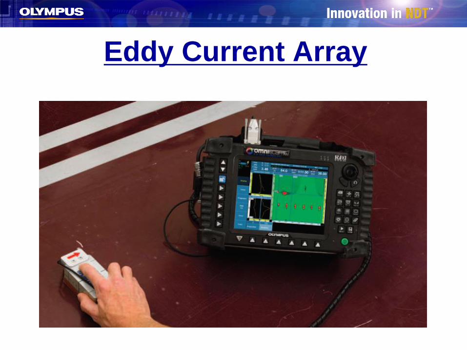
Eddy Current Array
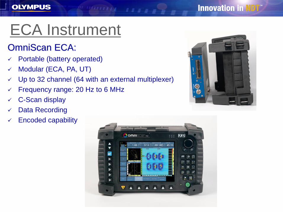
ECA InstrumentOmniScan ECA:✓ Portable (battery operated)
✓ Modular (ECA, PA, UT)
✓ Up to 32 channel (64 with an external multiplexer)
✓ Frequency range: 20 Hz to 6 MHz
✓ C-Scan display
✓ Data Recording
✓ Encoded capability
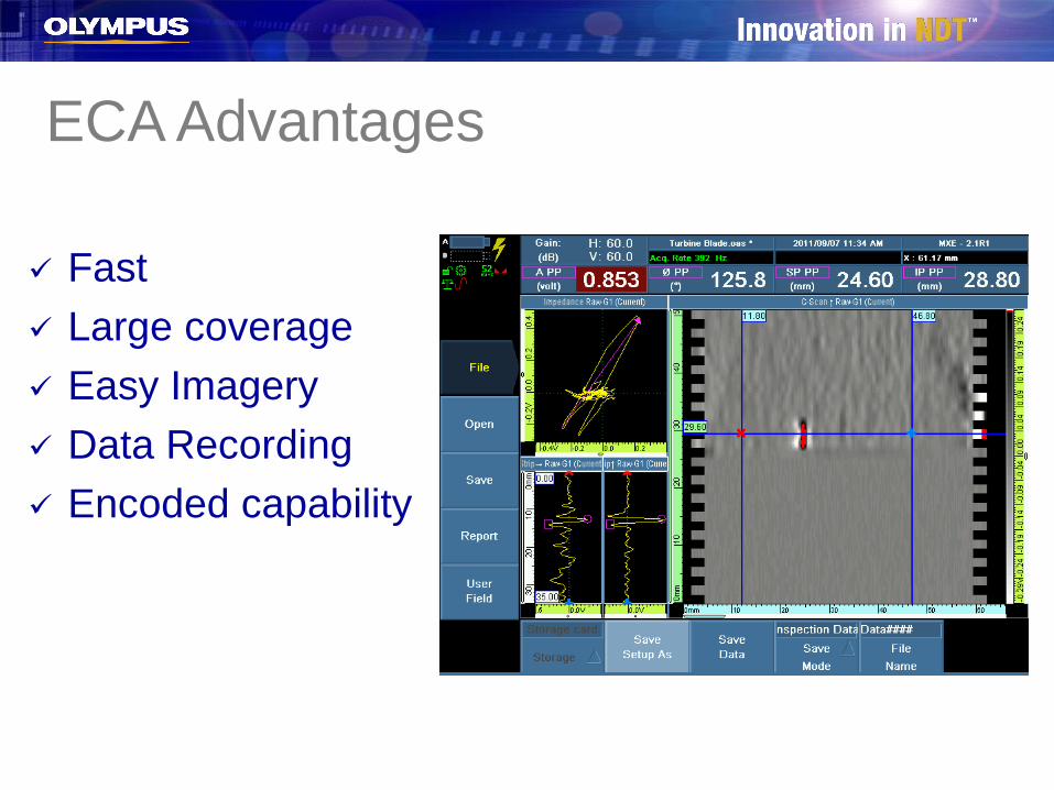
✓ Fast
✓ Large coverage
✓ Easy Imagery
✓ Data Recording
✓ Encoded capability
ECA Advantages
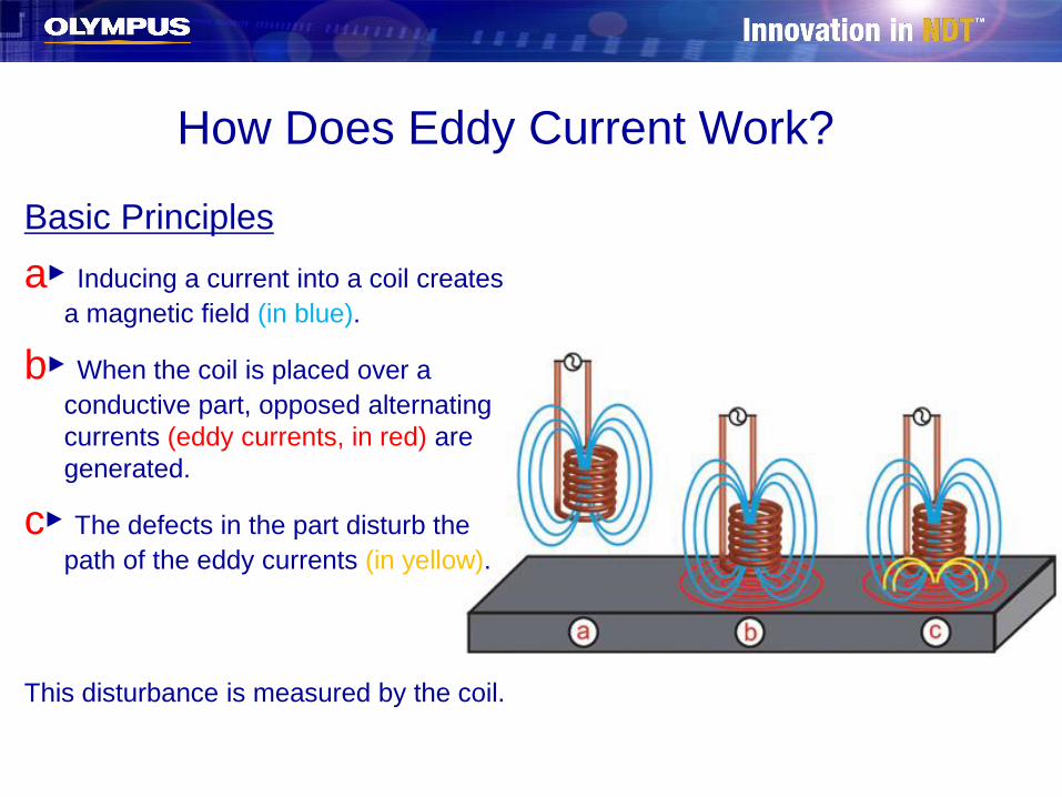
How Does Eddy Current Work?
Basic Principles
a► Inducing a current into a coil creates
a magnetic field (in blue).
b► When the coil is placed over a
conductive part, opposed alternating
currents (eddy currents, in red) are
generated.
c► The defects in the part disturb the
path of the eddy currents (in yellow).
This disturbance is measured by the coil.
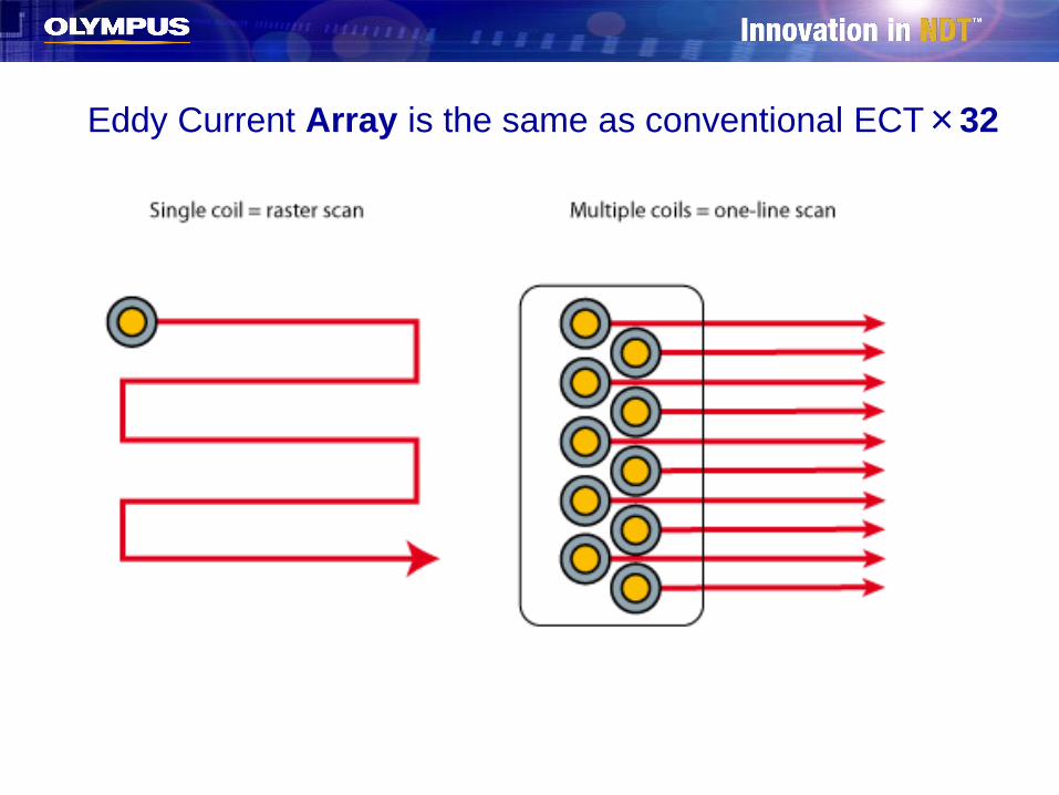
Eddy Current Array is the same as conventional ECT×32
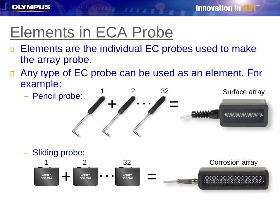
Elements are the individual EC probes used to make the array probe.
Any type of EC probe can be used as an element. For example:– Pencil probe:
– Sliding probe:
Elements in ECA Probe
…1 2 32
+ =Corrosion array
…1 2 32
+Surface array
=
Basic Principles
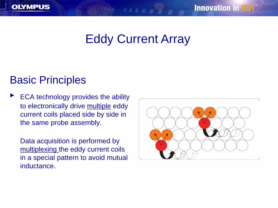
► ECA technology provides the ability
to electronically drive multiple eddy
current coils placed side by side in
the same probe assembly.
Data acquisition is performed by
multiplexing the eddy current coils
in a special pattern to avoid mutual
inductance.
Eddy Current Array
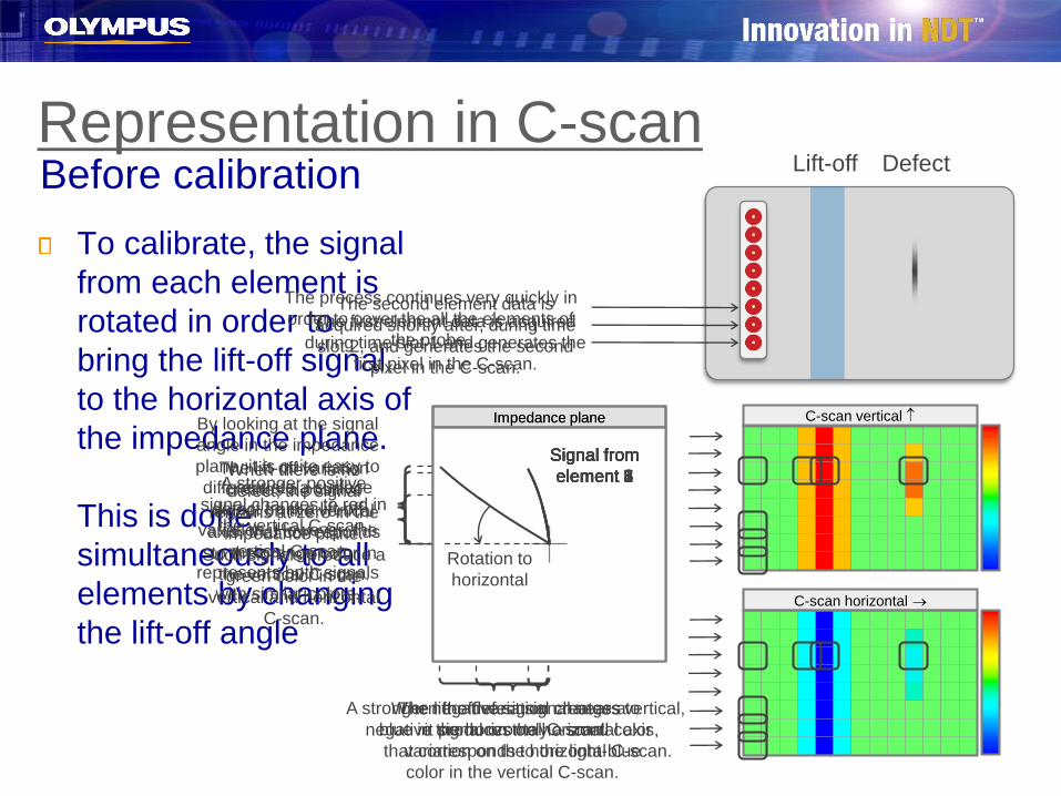
To calibrate, the signal
from each element is
rotated in order to
bring the lift-off signal
to the horizontal axis of
the impedance plane.
This is done
simultaneously to all
elements by changing
the lift-off angle
Signal from
element 6
Lift-off Defect
Representation in C-scanBefore calibration
C-scan vertical
C-scan horizontal →
Impedance plane
The lift-off variation
creates a positive
signal on the vertical
axis, that corresponds
to the orange color in
the vertical C-scan.
The lift-off variation creates a
negative signal on the horizontal axis,
that corresponds to the light-blue
color in the vertical C-scan.
A stronger positive
signal changes to red in
the vertical C-scan.
A stronger negative signal changes to
blue in the horizontal C-scan.
By looking at the signal
angle in the impedance
plane, it is quite easy to
differentiate a surface
defect from a lift-off
variation. However, the
vertical C-scan
represents both signals
with similar colors.
When the defect signal nears vertical,
it produces only a small color
variation on the horizontal C-scan.
When there is no
defect, the signal
remains at zero in the
impedance plane.
Such signals produce a
green color in the
vertical and horizontal
C-scan.
The first element data is acquired
during time slot 1 and generates the
first pixel in the C-scan.
The second element data is
acquired shortly after, during time
slot 2, and generates the second
pixel in the C-scan.
The process continues very quickly in
order to cover the all the elements of
the probe.
Impedance plane
Signal from
element 1
Signal from
element 2
Signal from
element 3
Signal from
element 4
Signal from
element 5
Signal from
element 6
Signal from
element 7
Signal from
element 8
Rotation to
horizontal
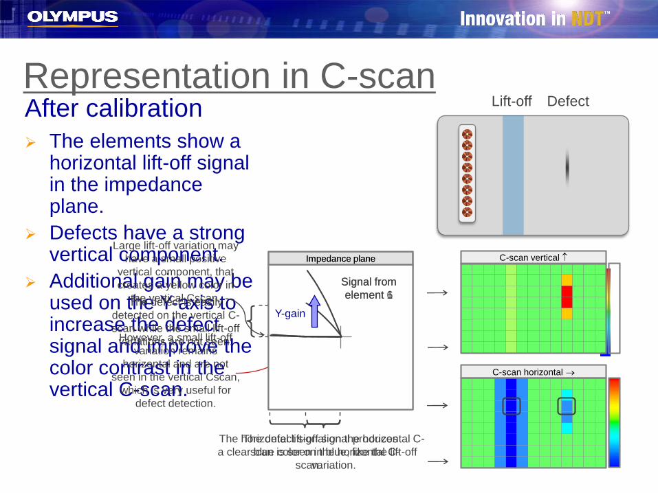
➢ The elements show a horizontal lift-off signal in the impedance plane.
➢ Defects have a strong vertical component.
➢ Additional gain may be used on the Y-axis to increase the defect signal and improve the color contrast in the vertical C-scan.
Signal from
element 6
Lift-off Defect
Representation in C-scanAfter calibration
C-scan horizontal →
Impedance plane
Large lift-off variation may
have a small positive
vertical component, that
creates a yellow color in
the vertical Cscan.
However, a small lift-off
variation remains
horizontal and are not
seen in the vertical Cscan,
which is very useful for
defect detection.
The horizontal lift-off signal produces
a clear blue color on the horizontal C-
scan.
The defect is easily
detected on the vertical C-
scan while the small lift-off
variations are not seen.
The defect signal on the horizontal C-
scan is seen in blue, like the lift-off
variation.
Impedance plane
Signal from
element 1
Signal from
element 6
Y-gain
C-scan vertical
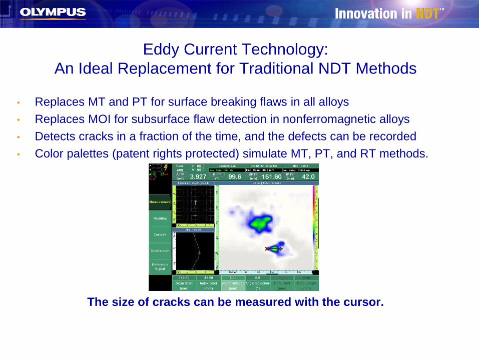
Eddy Current Technology:
An Ideal Replacement for Traditional NDT Methods
• Replaces MT and PT for surface breaking flaws in all alloys
• Replaces MOI for subsurface flaw detection in nonferromagnetic alloys
• Detects cracks in a fraction of the time, and the defects can be recorded
• Color palettes (patent rights protected) simulate MT, PT, and RT methods.
The size of cracks can be measured with the cursor.
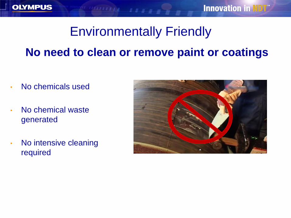
No need to clean or remove paint or coatings
• No chemicals used
• No chemical waste
generated
• No intensive cleaning
required
Environmentally Friendly
Inspection Through Paint
With the Eddy Current technique, the surface does not need to be perfectly
clean; cracks contaminated by oil or dirt are detected with reliability.
• Eliminates the need to strip expensive coatings
• Inspects surface and subsurface of nonferromagnetic materials without
removing the paint
• C-scan provides a reliable image of the condition of the material under
the paint
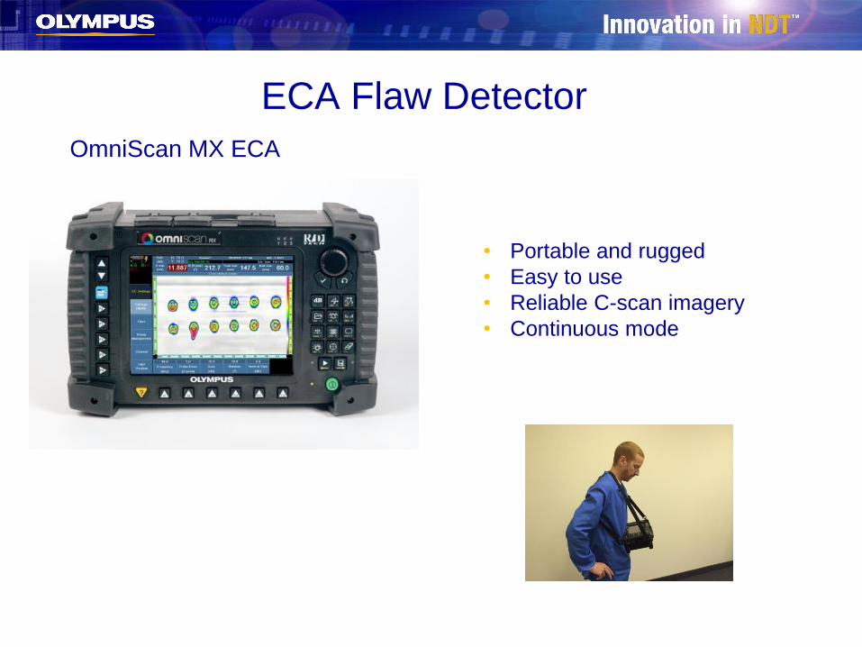
ECA Flaw Detector
OmniScan MX ECA
• Portable and rugged
• Easy to use
• Reliable C-scan imagery
• Continuous mode
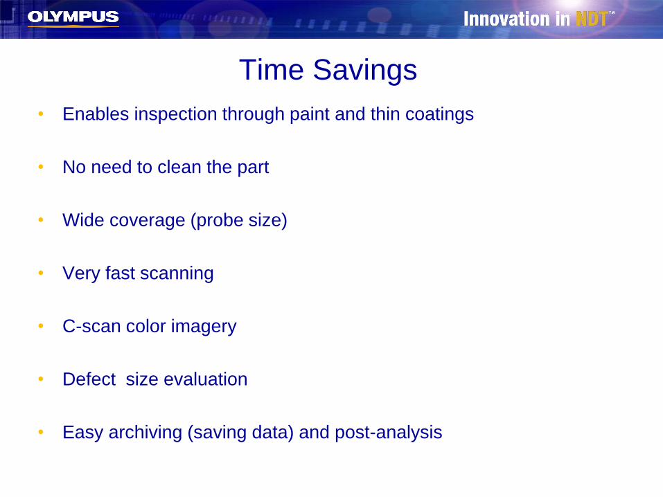
• Enables inspection through paint and thin coatings
• No need to clean the part
• Wide coverage (probe size)
• Very fast scanning
• C-scan color imagery
• Defect size evaluation
• Easy archiving (saving data) and post-analysis
Time Savings
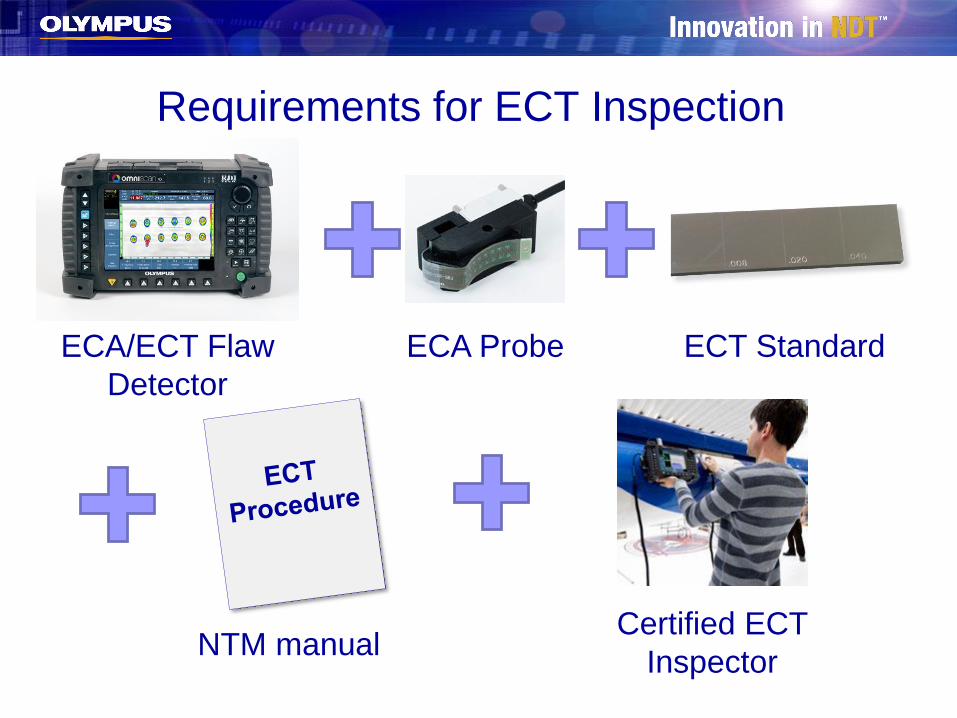
Requirements for ECT Inspection
ECA/ECT Flaw
Detector
ECA Probe ECT Standard
Certified ECT
InspectorNTM manual
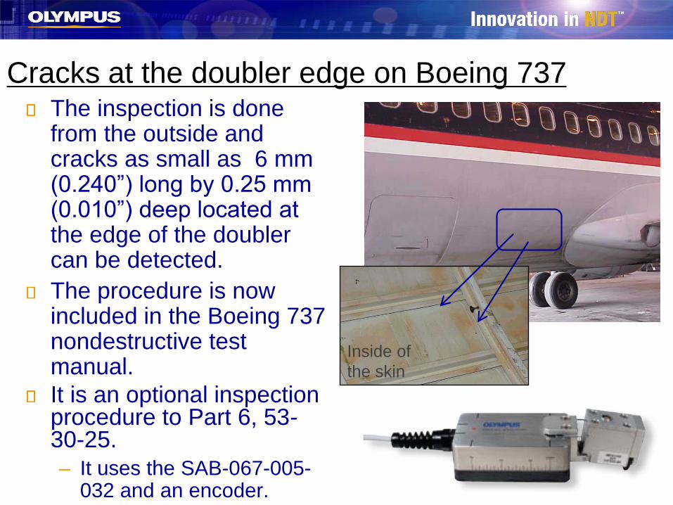
Cracks at the doubler edge on Boeing 737The inspection is done from the outside and cracks as small as 6 mm (0.240”) long by 0.25 mm (0.010”) deep located at the edge of the doubler can be detected.
The procedure is now included in the Boeing 737 nondestructive test manual.
It is an optional inspection procedure to Part 6, 53-30-25.
– It uses the SAB-067-005-032 and an encoder.
Inside of
the skin
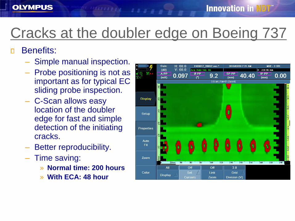
Cracks at the doubler edge on Boeing 737Benefits:
– Simple manual inspection.
– Probe positioning is not as important as for typical EC sliding probe inspection.
– C-Scan allows easy location of the doubler edge for fast and simple detection of the initiating cracks.
– Better reproducibility.
– Time saving:» Normal time: 200 hours
» With ECA: 48 hour
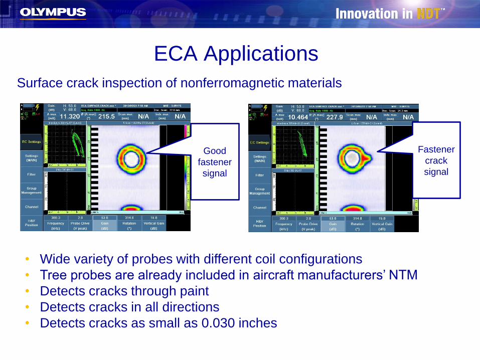
ECA Applications
Surface crack inspection of nonferromagnetic materials
Good
fastener
signal
Fastener
crack
signal
• Wide variety of probes with different coil configurations
• Tree probes are already included in aircraft manufacturers’ NTM
• Detects cracks through paint
• Detects cracks in all directions
• Detects cracks as small as 0.030 inches

ECA Applications (cont’d)
Subsurface-crack fastener inspection of nonferromagnetic materials
• Very good replacement for MOI
• Wide variety of probes with different coil configurations
• Two probes are already included in aircraft manufacturers’ NTM
• Detects cracks through paint
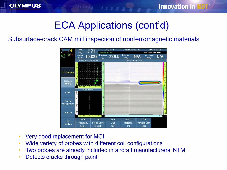
ECA Applications (cont’d)
Subsurface-crack CAM mill inspection of nonferromagnetic materials
• Very good replacement for MOI
• Wide variety of probes with different coil configurations
• Two probes are already included in aircraft manufacturers’ NTM
• Detects cracks through paint
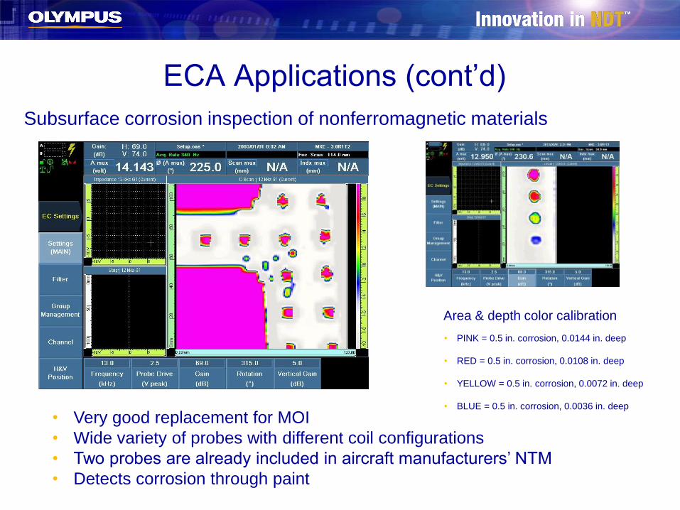
ECA Applications (cont’d)
Subsurface corrosion inspection of nonferromagnetic materials
• Very good replacement for MOI
• Wide variety of probes with different coil configurations
• Two probes are already included in aircraft manufacturers’ NTM
• Detects corrosion through paint
Area & depth color calibration
• PINK = 0.5 in. corrosion, 0.0144 in. deep
• RED = 0.5 in. corrosion, 0.0108 in. deep
• YELLOW = 0.5 in. corrosion, 0.0072 in. deep
• BLUE = 0.5 in. corrosion, 0.0036 in. deep
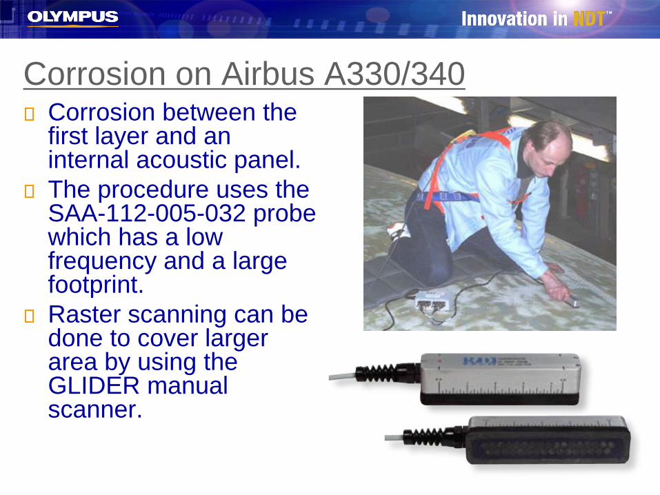
Corrosion on Airbus A330/340Corrosion between the first layer and an internal acoustic panel.
The procedure uses the SAA-112-005-032 probe which has a low frequency and a large footprint.
Raster scanning can be done to cover larger area by using the GLIDER manual scanner.
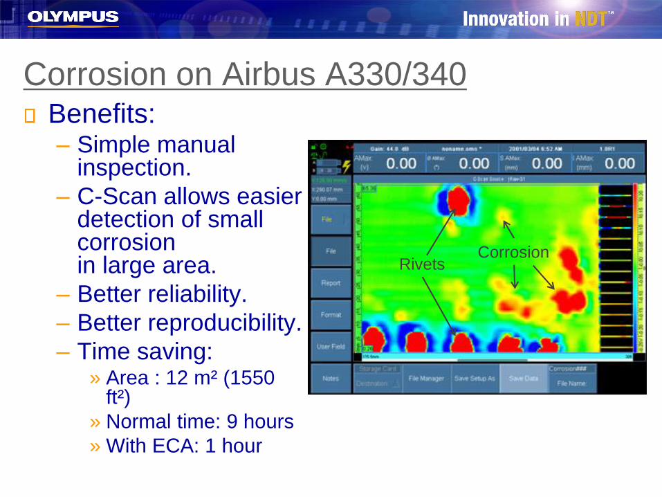
Corrosion on Airbus A330/340Benefits:– Simple manual
inspection.
– C-Scan allows easier detection of small corrosionin large area.
– Better reliability.
– Better reproducibility.
– Time saving:» Area : 12 m² (1550
ft²)
» Normal time: 9 hours
» With ECA: 1 hour
RivetsCorrosion
ECA indications with red dye color palette
(patent rights protected)
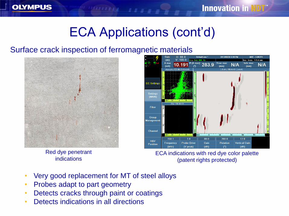
ECA Applications (cont’d)
Surface crack inspection of ferromagnetic materials
Red dye penetrant
indications
• Very good replacement for MT of steel alloys
• Probes adapt to part geometry
• Detects cracks through paint or coatings
• Detects indications in all directions
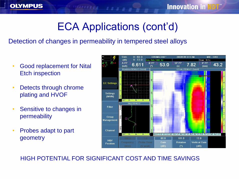
ECA Applications (cont’d)
Detection of changes in permeability in tempered steel alloys
• Good replacement for Nital
Etch inspection
• Detects through chrome
plating and HVOF
• Sensitive to changes in
permeability
• Probes adapt to part
geometry
HIGH POTENTIAL FOR SIGNIFICANT COST AND TIME SAVINGS
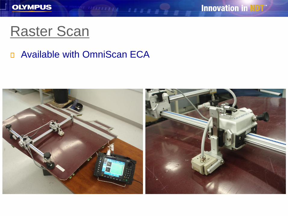
Raster Scan
Available with OmniScan ECA
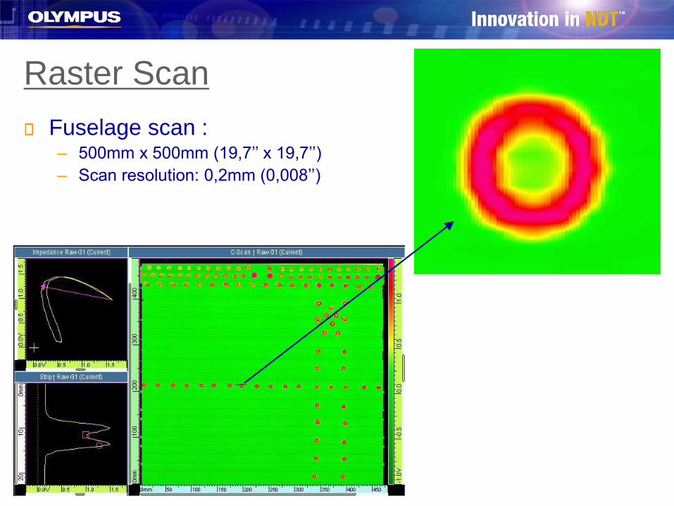
Raster Scan
Fuselage scan :– 500mm x 500mm (19,7’’ x 19,7’’)
– Scan resolution: 0,2mm (0,008’’)
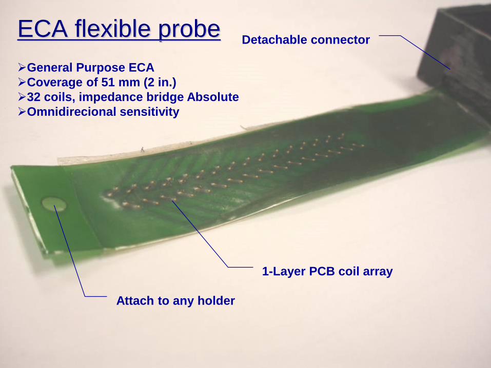
ECA flexible probeDetachable connector
1-Layer PCB coil array
Attach to any holder
➢General Purpose ECA
➢Coverage of 51 mm (2 in.)
➢32 coils, impedance bridge Absolute
➢Omnidirecional sensitivity
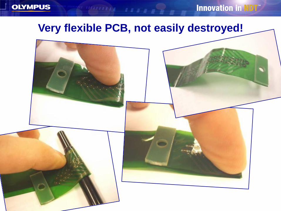
Very flexible PCB, not easily destroyed!

FLEX PROBE: Applications
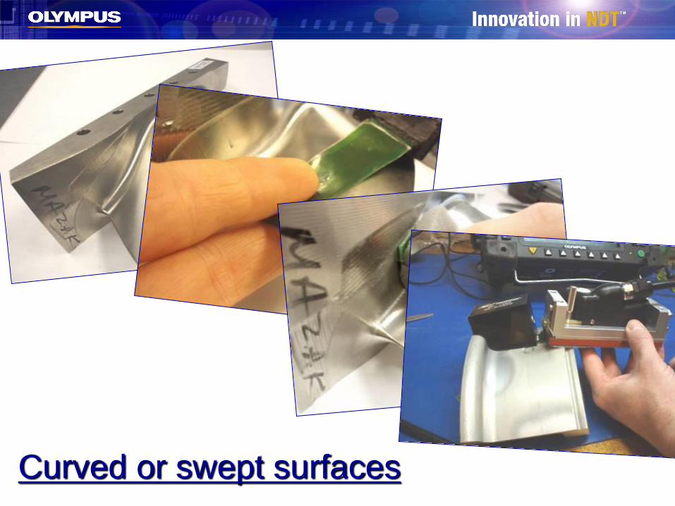
Curved or swept surfaces
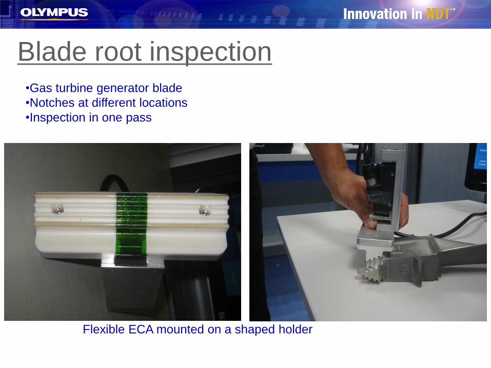
Blade root inspection•Gas turbine generator blade
•Notches at different locations
•Inspection in one pass
Flexible ECA mounted on a shaped holder
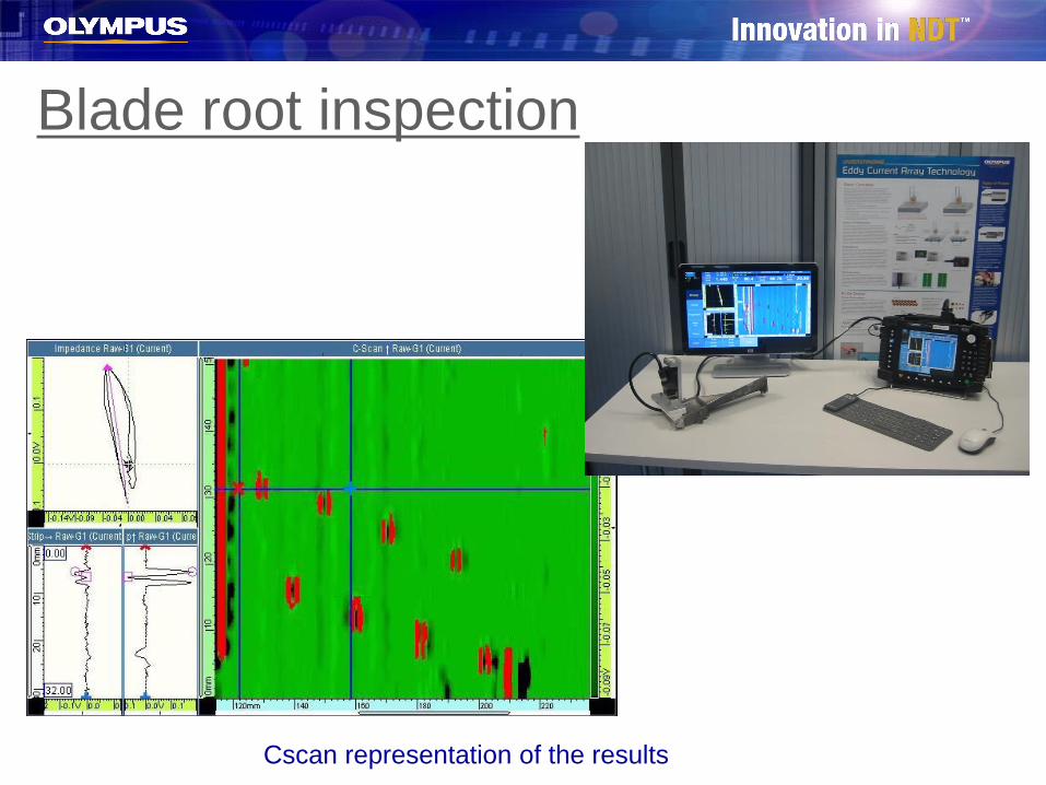
Blade root inspection
Cscan representation of the results
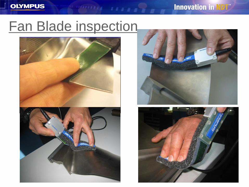
Fan Blade inspection
ConclusionEddy Current Array is an ideal replacement for MT, PT, MOI, and Nital Etch
inspection methods.
Advantages of ECA
• Portable: The OmniScan can be used with a chest harness and two batteries.
• Lightweight: The OmniScan weighs only 10.1 pounds with one battery.
• Easy to use: The OmniScan 3.0R2 software is fast and easy.
• Rugged instrument: The OmniScan has a sturdy casing with protective
bumpers.
• Fast scanning: Scans at speeds of 4 feet/minute to 30 feet/minute with a 1 to 6
inch coverage, depending on the probe used.
• 100% coverage: The ECA to ECT probe toggle option of the OmniScan makes
it possible to perform 100% coverage inspections with the press of a button.
• Sizing capabilities: Evaluates the dimension of indications.
New Aircraft Procedures
CFM CFM56-7B, 5B, 5A engine blade
root inspection
CFM56-7B engine dovetail slot inspection
CFM56 all versions, TRF inspection kit
GE90 engine dovetail slot inspection
GP7200 engine dovetail slot inspection
Airbus A330 corrosion inspection

Thank you, and travel safely with Olympus Australia