Embed Size (px)
Citation preview
Page B–1IronHorse® Shaft Mount Gearbox User Manual – 1st Edition, Revision A – 09/13/2019
Gearbox Selection
BBBappendixappendixappendix
table of Contents
Shaft Mount Gearbox Selection Procedure � � � � � � � � � � � � � � � � � � � � � � � � � � � � � �B–2How to Select � � � � � � � � � � � � � � � � � � � � � � � � � � � � � � � � � � � � � � � � � � � � � � � � � B–2Example of SMR Gearbox Selection Procedure � � � � � � � � � � � � � � � � � � � � � � � � � � � � � � � B–3
A�G�M�A� Load Classification Numbers � � � � � � � � � � � � � � � � � � � � � � � � � � � � � � � � �B–4Shaft Mount Reducers with Uniform Power Source � � � � � � � � � � � � � � � � � � � � � � � � � � � � B–4
Page B–2 IronHorse® Shaft Mount Gearbox User Manual – 1st Edition, Revision A – 09/13/2019
Appendix B: Gearbox Selection
sHAfT mouNT GeARbox selecTIoN PRoceduReFollow the procedure below to select Screw Conveyor Shaft Mount Reducers (SMR) up to 40 horsepower and/or output speeds to 200 RPM, using AGMA recommended application numbers as generally described herein.
hoW To seleCT
1) Determine Class of Service (See “Classes of Service and Service Factors” on page 2–2) To determine Load Classification for applications under normal conditions, find the type application and duty cycle that most closely matches your specific application. For a detailed list of applications and classifications numbers, see “A.G.M.A. Load Classification Numbers” on page B–4. Class I: Steady load not exceeding Motor HP rating and light shock loads during 10 hours a day. Moderate shock loads are allowable if operation is intermittent. Class II: Steady load not exceeding Motor HP rating for over 10 hours a day. Moderate shock loads are allowable during 10 hours a day. Class III: Moderate shock loads for over 10 hours a day. Heavy shock loads are allowable during 10 hours a day.
2) Determine Reducer Size (See “Mechanical Ratings” on page 2–5) To choose the correct size SMR gearbox find the Service Class Column that accurately represents the severity of the application, and then finding the correct gearbox output speed will denote the SMR reducer case size and ratio.
3) Select the corresponding Screw Conveyor Flange and correct Screw Conveyor Shaft Diameter (See “Accessories Selection” on page 4–2) It is necessary to select a SMR gearbox that not only matches the proper HP and Class of Service, but must also clearly accommodate the CEMA* trough-end. Select the 3-Hole Screw Conveyor Shaft that’s compatible with the schedule pipe diameter of the screw conveyor. *Conveyor Equipment Manufacturer Association
4) Select the proper V-belt Drive Arrangement All SMR reducers utilizing a Motor Mount require a V-belt and Sheave combination that in conjunction with the Motor (HP & RPM) and gearbox ratio, provide the desired output speed to the driven shaft. In addition to selecting the proper sheave ratio, care must be taken in selecting the correct V-Belt cross-section and number of belts to insure an adequate Service Factor (SF). In many instances, those that specify the V-belt & pulley sizes try to pick a system that prevents nuisance failures, yet still is the Weak Link; as V-belt drives are far less expensive and quicker to replace than damaged gearboxes. If needed, please consult AutomationDirect Tech Support for proper V-belt drive selection.
5) Select additional Accessories (See “Accessories Selection” on page 4–2) In the accessories section of the catalog a selection of Motor Mounts, Belt Guards, Bushing Kits, and Backstop clutches can be found. The part numbers are easily selected, as they share nomenclature in common with the corresponding SMR case size. Backstops are a one-way clutch that prevent the driven load of an incline or vertical load from back-driving due to gravity. Always use the same brand of backstop as the manufacturer of the SMR gearbox.
Appendix B: Gearbox Selection
Page B–3IronHorse® Shaft Mount Gearbox User Manual – 1st Edition, Revision A – 09/13/2019
example oF smr gearbox seleCTion proCedure
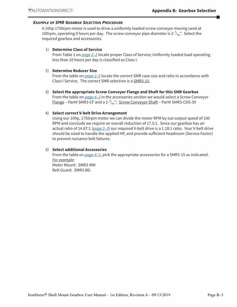
A 10hp 1750rpm motor is used to drive a uniformly loaded screw conveyor moving sand at 100rpm, operating 8 hours per day. The screw conveyor pipe diameter is 2-⁷⁄₁₆”. Select the required gearbox and accessories.
1) Determine Class of Service From Table 1 on page 2–2 locate proper Class of Service; Uniformly loaded load operating less than 10 hours per day is classified as Class I.
2) Determine Reducer Size From the table on page 2–5 locate the correct SMR case size and ratio in accordance with Class I Service. The correct SMR selection is a SMR3-15.
3) Select the appropriate Screw Conveyor Flange and Shaft for this SMR Gearbox From the table on page 4–2 in the accessories section we would select a Screw Conveyor Flange – Part# SMR3-CF and a 2-⁷⁄₁₆”; Screw Conveyor Shaft – Part# SMR3-CDS-39
4) Select correct V-belt Drive Arrangement Using our 10hp, 1750rpm motor we can divide the motor RPM by out output speed of 100 RPM and conclude we require an overall reduction of 17.5:1. Since our gearbox has an actual ratio of 14.87:1 (page 2–3) our required V-belt drive is a 1.18:1 ratio. Your V-belt drive should be sized to handle the applied HP, and provide sufficient headroom (Service Factor) to prevent nuisance belt failures.
5) Select additional Accessories From the table on page 4–2, pick the appropriate accessories for a SMR3-15 as indicated. For example: Motor Mount: SMR3-MM Belt Guard: SMR3-BG

Page B–4 IronHorse® Shaft Mount Gearbox User Manual – 1st Edition, Revision A – 09/13/2019
Appendix B: Gearbox Selection
A.G.m.A. loAd clAssIfIcATIoN NumbeRs
shaFT mounT reduCers WiTh uniForm poWer sourCe
A.G.M.A. Class Numbers for Shaft Mount ReducersApplication
Service Hours per DayUp to 3 3 to 10 Over 10
Agitators (mixers)
Pure liquids I I II
Liquids and solids I II II
Liquids – variable density I II II
Blowers
Centrifugal I I II
Lobe I II II
Vane I II II
Brewing and distilling
Bottling machinery I I II
Brew kettles – continuous duty II II II
Cookers – continuous duty II II II
Mash tubs – continuous duty II II II
Scale hopper – frequent starts II II II
Can filling machines I I II
Car dumpers I III III
Car pullers I II II
Clarifiers I I II
Classifiers I II II
Clay working machinery
Brick press II III III
Briquette machine II III III
Pug mill I II II
Compactors III III III
Compressors
Centrifugal I I II
Lobe I II II
Reciprocating, multi-cylinder II II III
Reciprocating, single-cylinder III III III1) Crane drives are to be selected based on gear tooth bending strength, using the numeric service factors in this table.
Service factor in durability shall be a minimum of 1.00.2) Anti-friction bearings only.3) A class number of I may be applied at base speed of a super calender operating over-speed range or part range
constant horsepower, part range constant torque where the constant horsepower speed range is greater than 1.5 to 1. A class number of II is applicable to super calenders operating over the entire speed range at constant torque or where the constant horsepower speed range is less than 1.5 to 1.
( table continued next page )
Appendix B: Gearbox Selection
Page B–5IronHorse® Shaft Mount Gearbox User Manual – 1st Edition, Revision A – 09/13/2019
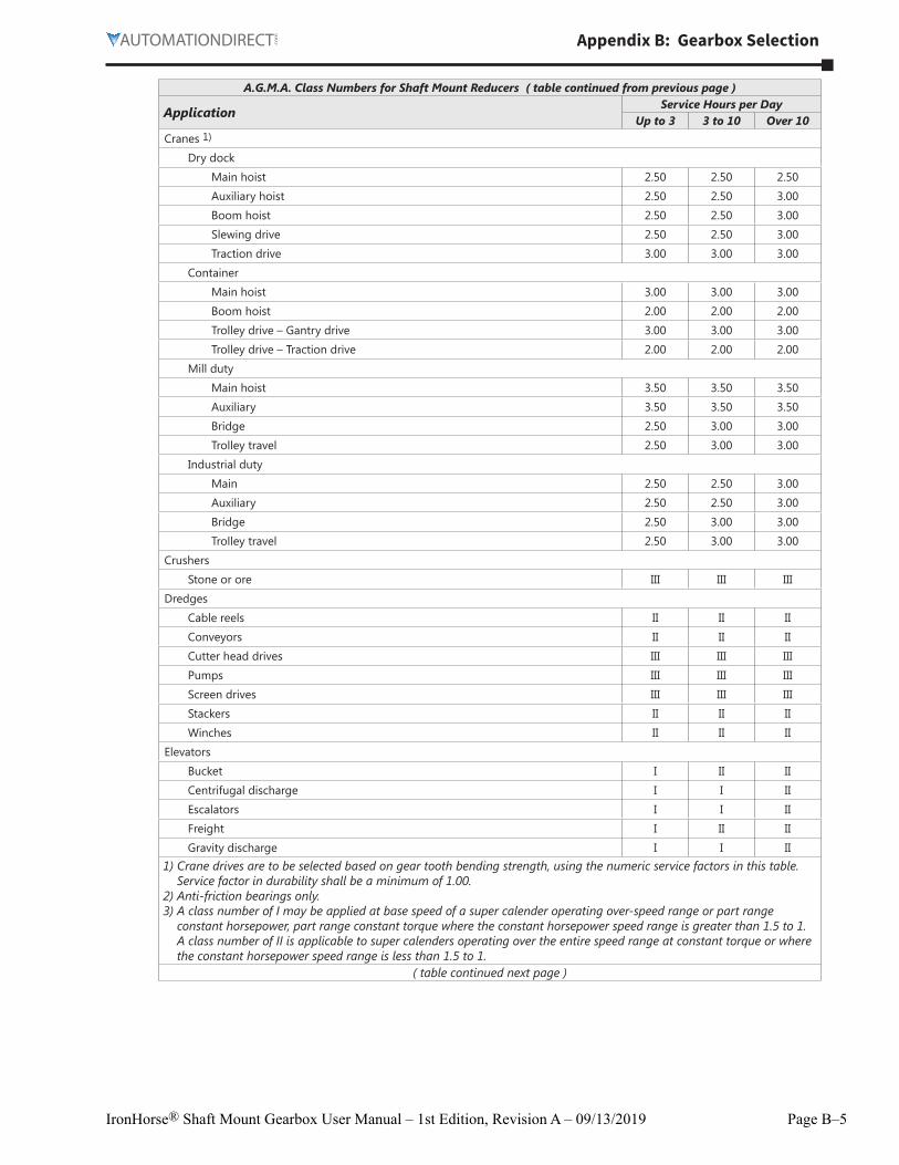
A.G.M.A. Class Numbers for Shaft Mount Reducers ( table continued from previous page )
ApplicationService Hours per Day
Up to 3 3 to 10 Over 10Cranes 1)
Dry dock
Main hoist 2�50 2�50 2�50
Auxiliary hoist 2�50 2�50 3�00
Boom hoist 2�50 2�50 3�00
Slewing drive 2�50 2�50 3�00
Traction drive 3�00 3�00 3�00
Container
Main hoist 3�00 3�00 3�00
Boom hoist 2�00 2�00 2�00
Trolley drive – Gantry drive 3�00 3�00 3�00
Trolley drive – Traction drive 2�00 2�00 2�00
Mill duty
Main hoist 3�50 3�50 3�50
Auxiliary 3�50 3�50 3�50
Bridge 2�50 3�00 3�00
Trolley travel 2�50 3�00 3�00
Industrial duty
Main 2�50 2�50 3�00
Auxiliary 2�50 2�50 3�00
Bridge 2�50 3�00 3�00
Trolley travel 2�50 3�00 3�00
Crushers
Stone or ore III III III
Dredges
Cable reels II II II
Conveyors II II II
Cutter head drives III III III
Pumps III III III
Screen drives III III III
Stackers II II II
Winches II II II
Elevators
Bucket I II II
Centrifugal discharge I I II
Escalators I I II
Freight I II II
Gravity discharge I I II1) Crane drives are to be selected based on gear tooth bending strength, using the numeric service factors in this table.
Service factor in durability shall be a minimum of 1.00.2) Anti-friction bearings only.3) A class number of I may be applied at base speed of a super calender operating over-speed range or part range
constant horsepower, part range constant torque where the constant horsepower speed range is greater than 1.5 to 1. A class number of II is applicable to super calenders operating over the entire speed range at constant torque or where the constant horsepower speed range is less than 1.5 to 1.
( table continued next page )
Page B–6 IronHorse® Shaft Mount Gearbox User Manual – 1st Edition, Revision A – 09/13/2019
Appendix B: Gearbox Selection
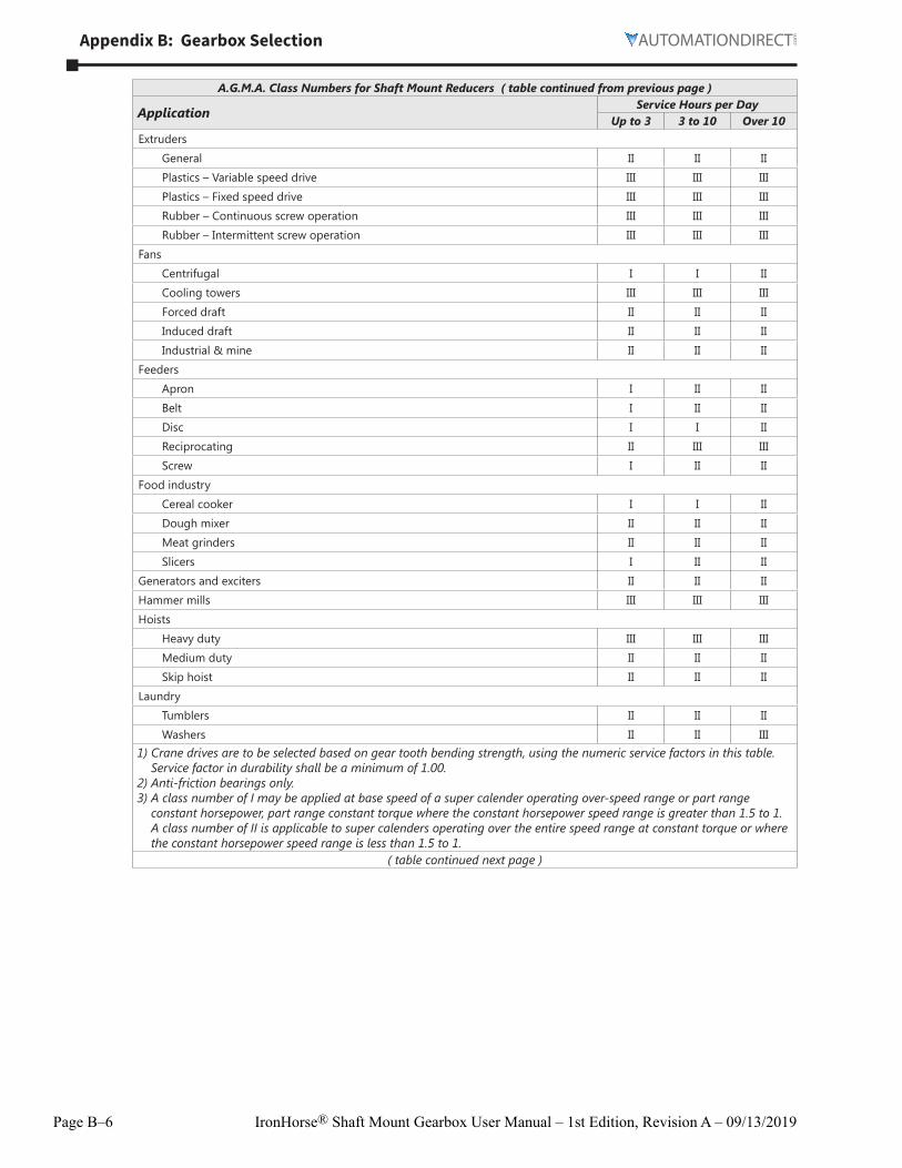
A.G.M.A. Class Numbers for Shaft Mount Reducers ( table continued from previous page )
ApplicationService Hours per Day
Up to 3 3 to 10 Over 10Extruders
General II II II
Plastics – Variable speed drive III III III
Plastics – Fixed speed drive III III III
Rubber – Continuous screw operation III III III
Rubber – Intermittent screw operation III III III
Fans
Centrifugal I I II
Cooling towers III III III
Forced draft II II II
Induced draft II II II
Industrial & mine II II II
Feeders
Apron I II II
Belt I II II
Disc I I II
Reciprocating II III III
Screw I II II
Food industry
Cereal cooker I I II
Dough mixer II II II
Meat grinders II II II
Slicers I II II
Generators and exciters II II II
Hammer mills III III III
Hoists
Heavy duty III III III
Medium duty II II II
Skip hoist II II II
Laundry
Tumblers II II II
Washers II II III1) Crane drives are to be selected based on gear tooth bending strength, using the numeric service factors in this table.
Service factor in durability shall be a minimum of 1.00.2) Anti-friction bearings only.3) A class number of I may be applied at base speed of a super calender operating over-speed range or part range
constant horsepower, part range constant torque where the constant horsepower speed range is greater than 1.5 to 1. A class number of II is applicable to super calenders operating over the entire speed range at constant torque or where the constant horsepower speed range is less than 1.5 to 1.
( table continued next page )
Appendix B: Gearbox Selection
Page B–7IronHorse® Shaft Mount Gearbox User Manual – 1st Edition, Revision A – 09/13/2019
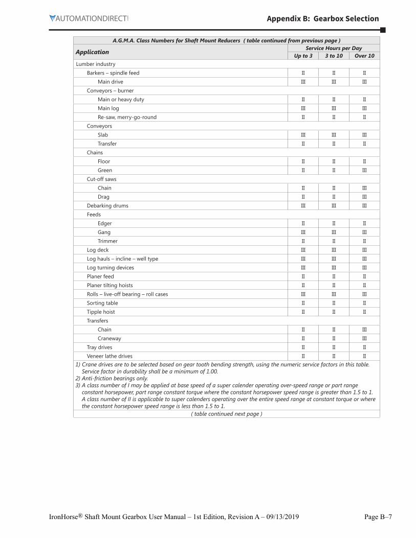
A.G.M.A. Class Numbers for Shaft Mount Reducers ( table continued from previous page )
ApplicationService Hours per Day
Up to 3 3 to 10 Over 10Lumber industry
Barkers – spindle feed II II II
Main drive III III III
Conveyors – burner
Main or heavy duty II II II
Main log III III III
Re-saw, merry-go-round II II II
Conveyors
Slab III III III
Transfer II II II
Chains
Floor II II II
Green II II III
Cut-off saws
Chain II II III
Drag II II III
Debarking drums III III III
Feeds
Edger II II II
Gang III III III
Trimmer II II II
Log deck III III III
Log hauls – incline – well type III III III
Log turning devices III III III
Planer feed II II II
Planer tilting hoists II II II
Rolls – live-off bearing – roll cases III III III
Sorting table II II II
Tipple hoist II II II
Transfers
Chain II II III
Craneway II II III
Tray drives II II II
Veneer lathe drives II II II1) Crane drives are to be selected based on gear tooth bending strength, using the numeric service factors in this table.
Service factor in durability shall be a minimum of 1.00.2) Anti-friction bearings only.3) A class number of I may be applied at base speed of a super calender operating over-speed range or part range
constant horsepower, part range constant torque where the constant horsepower speed range is greater than 1.5 to 1. A class number of II is applicable to super calenders operating over the entire speed range at constant torque or where the constant horsepower speed range is less than 1.5 to 1.
( table continued next page )
Page B–8 IronHorse® Shaft Mount Gearbox User Manual – 1st Edition, Revision A – 09/13/2019
Appendix B: Gearbox Selection
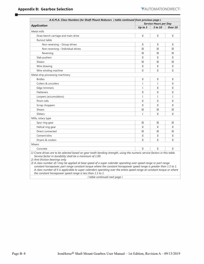
A.G.M.A. Class Numbers for Shaft Mount Reducers ( table continued from previous page )
ApplicationService Hours per Day
Up to 3 3 to 10 Over 10Metal mills
Draw bench carriage and main drive II II II
Runout table
Non-reversing – Group drives II II II
Non-reversing – Individual drives III III III
Reversing III III III
Slab pushers II II II
Shears III III III
Wire drawing II II II
Wire winding machine II II II
Metal strip processing machinery
Bridles II II II
Coilers & uncoilers I I II
Edge trimmers I II II
Flatteners II II II
Loopers (accumulators) I I I
Pinch rolls II II II
Scrap choppers II II II
Shears III III III
Slitters I II II
Mills, rotary type
Spur ring gear III III III
Helical ring gear II II II
Direct connected III III III
Cement kilns II II II
Dryers & coolers II II II
Mixers
Concrete II II II1) Crane drives are to be selected based on gear tooth bending strength, using the numeric service factors in this table.
Service factor in durability shall be a minimum of 1.00.2) Anti-friction bearings only.3) A class number of I may be applied at base speed of a super calender operating over-speed range or part range
constant horsepower, part range constant torque where the constant horsepower speed range is greater than 1.5 to 1. A class number of II is applicable to super calenders operating over the entire speed range at constant torque or where the constant horsepower speed range is less than 1.5 to 1.
( table continued next page )
Appendix B: Gearbox Selection
Page B–9IronHorse® Shaft Mount Gearbox User Manual – 1st Edition, Revision A – 09/13/2019
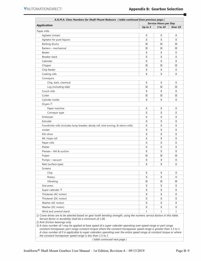
A.G.M.A. Class Numbers for Shaft Mount Reducers ( table continued from previous page )
ApplicationService Hours per Day
Up to 3 3 to 10 Over 10Paper mills
Agitator (mixer) II II II
Agitator for pure liquors II II II
Barking drums III III III
Barkers – mechanical III III III
Beater II II II
Breaker stack II II II
Calender II II II
Chipper III III III
Chip feeder II II II
Coating rolls II II II
Conveyors
Chip, bark, chemical II II II
Log (including slab) III III III
Couch rolls II II II
Cutter III III III
Cylinder molds II II II
Dryers 2)
Paper machine II II II
Conveyor type II II II
Embosser II II II
Extruder II II II
Fourdrinier rolls (includes lump breaker, dandy roll, wire turning, & return rolls) II II II
Jordan II II II
Kiln drive II II II
Mt� Hope roll II II II
Paper rolls II II II
Platter II II II
Presses – felt & suction II II II
Pulper III III III
Pumps – vacuum II II II
Reel (surface type) II II II
Screens
Chip II II II
Rotary II II II
Vibrating III III III
Size press II II II
Super calender 3) II II II
Thickener (AC motor) II II II
Thickener (DC motor) II II II
Washer (AC motor) II II II
Washer (DC motor) II II II
Wind and unwind stand I I I1) Crane drives are to be selected based on gear tooth bending strength, using the numeric service factors in this table.
Service factor in durability shall be a minimum of 1.00.2) Anti-friction bearings only.3) A class number of I may be applied at base speed of a super calender operating over-speed range or part range
constant horsepower, part range constant torque where the constant horsepower speed range is greater than 1.5 to 1. A class number of II is applicable to super calenders operating over the entire speed range at constant torque or where the constant horsepower speed range is less than 1.5 to 1.
( table continued next page )
Page B–10 IronHorse® Shaft Mount Gearbox User Manual – 1st Edition, Revision A – 09/13/2019
Appendix B: Gearbox Selection
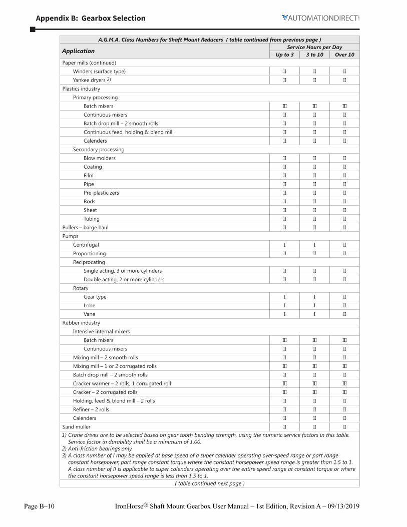
A.G.M.A. Class Numbers for Shaft Mount Reducers ( table continued from previous page )
ApplicationService Hours per Day
Up to 3 3 to 10 Over 10Paper mills (continued)
Winders (surface type) II II II
Yankee dryers 2) II II II
Plastics industry
Primary processing
Batch mixers III III III
Continuous mixers II II II
Batch drop mill – 2 smooth rolls II II II
Continuous feed, holding & blend mill II II II
Calenders II II II
Secondary processing
Blow molders II II II
Coating II II II
Film II II II
Pipe II II II
Pre-plasticizers II II II
Rods II II II
Sheet II II II
Tubing II II II
Pullers – barge haul II II II
Pumps
Centrifugal I I II
Proportioning II II II
Reciprocating
Single acting, 3 or more cylinders II II II
Double acting, 2 or more cylinders II II II
Rotary
Gear type I I II
Lobe I I II
Vane I I II
Rubber industry
Intensive internal mixers
Batch mixers III III III
Continuous mixers II II II
Mixing mill – 2 smooth rolls II II II
Mixing mill – 1 or 2 corrugated rolls III III III
Batch drop mill – 2 smooth rolls II II II
Cracker warmer – 2 rolls; 1 corrugated roll III III III
Cracker – 2 corrugated rolls III III III
Holding, feed & blend mill – 2 rolls II II II
Refiner – 2 rolls II II II
Calenders II II II
Sand muller II II II1) Crane drives are to be selected based on gear tooth bending strength, using the numeric service factors in this table.
Service factor in durability shall be a minimum of 1.00.2) Anti-friction bearings only.3) A class number of I may be applied at base speed of a super calender operating over-speed range or part range
constant horsepower, part range constant torque where the constant horsepower speed range is greater than 1.5 to 1. A class number of II is applicable to super calenders operating over the entire speed range at constant torque or where the constant horsepower speed range is less than 1.5 to 1.
( table continued next page )
Appendix B: Gearbox Selection
Page B–11IronHorse® Shaft Mount Gearbox User Manual – 1st Edition, Revision A – 09/13/2019
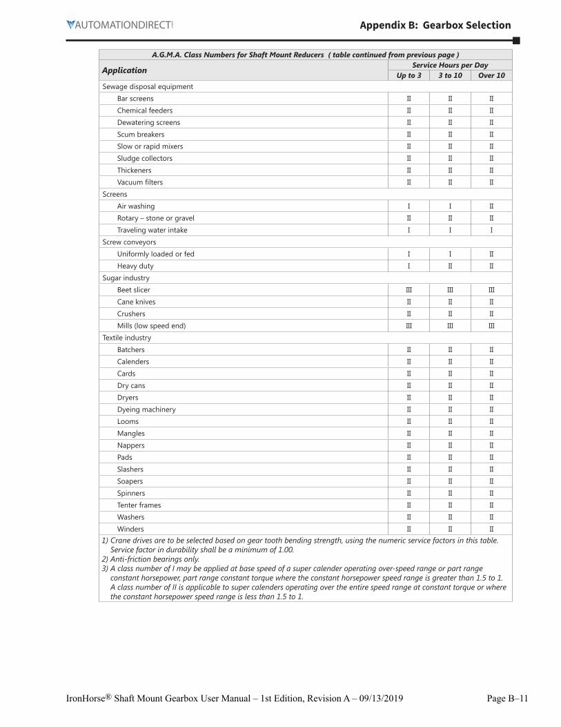
A.G.M.A. Class Numbers for Shaft Mount Reducers ( table continued from previous page )
ApplicationService Hours per Day
Up to 3 3 to 10 Over 10Sewage disposal equipment
Bar screens II II II
Chemical feeders II II II
Dewatering screens II II II
Scum breakers II II II
Slow or rapid mixers II II II
Sludge collectors II II II
Thickeners II II II
Vacuum filters II II II
Screens
Air washing I I II
Rotary – stone or gravel II II II
Traveling water intake I I I
Screw conveyors
Uniformly loaded or fed I I II
Heavy duty I II II
Sugar industry
Beet slicer III III III
Cane knives II II II
Crushers II II II
Mills (low speed end) III III III
Textile industry
Batchers II II II
Calenders II II II
Cards II II II
Dry cans II II II
Dryers II II II
Dyeing machinery II II II
Looms II II II
Mangles II II II
Nappers II II II
Pads II II II
Slashers II II II
Soapers II II II
Spinners II II II
Tenter frames II II II
Washers II II II
Winders II II II1) Crane drives are to be selected based on gear tooth bending strength, using the numeric service factors in this table.
Service factor in durability shall be a minimum of 1.00.2) Anti-friction bearings only.3) A class number of I may be applied at base speed of a super calender operating over-speed range or part range
constant horsepower, part range constant torque where the constant horsepower speed range is greater than 1.5 to 1. A class number of II is applicable to super calenders operating over the entire speed range at constant torque or where the constant horsepower speed range is less than 1.5 to 1.
Page B–12 IronHorse® Shaft Mount Gearbox User Manual – 1st Edition, Revision A – 09/13/2019
Appendix B: Gearbox Selection
BLANKPAGE
![Technical data rev 02...Master file: Technical data_rev_02.xls 01-09-15 ATEX CONDITION [ Group II ] - 2014/34/EU Gearbox configuration GEARBOX APPLICATION UTILITY Hours used for Selection](https://img.pdfslide.us/doc/110x75/6101513ed9568547e8697cf8/technical-data-rev-02-master-file-technical-datarev02xls-01-09-15-atex-condition.jpg)