Embed Size (px)
Citation preview
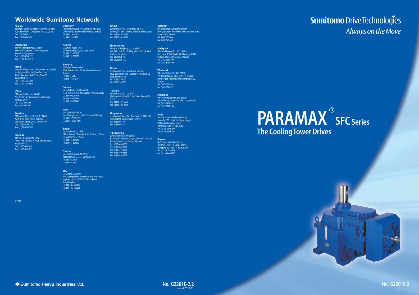
No. G2201E-2No. G2201E-2.2
PARAMAX SFC SeriesThe Cooling Tower Drives
®
Issued 2010.05
CW23
1
Features
Optimised for cooling tower use
1 Selection Criteria
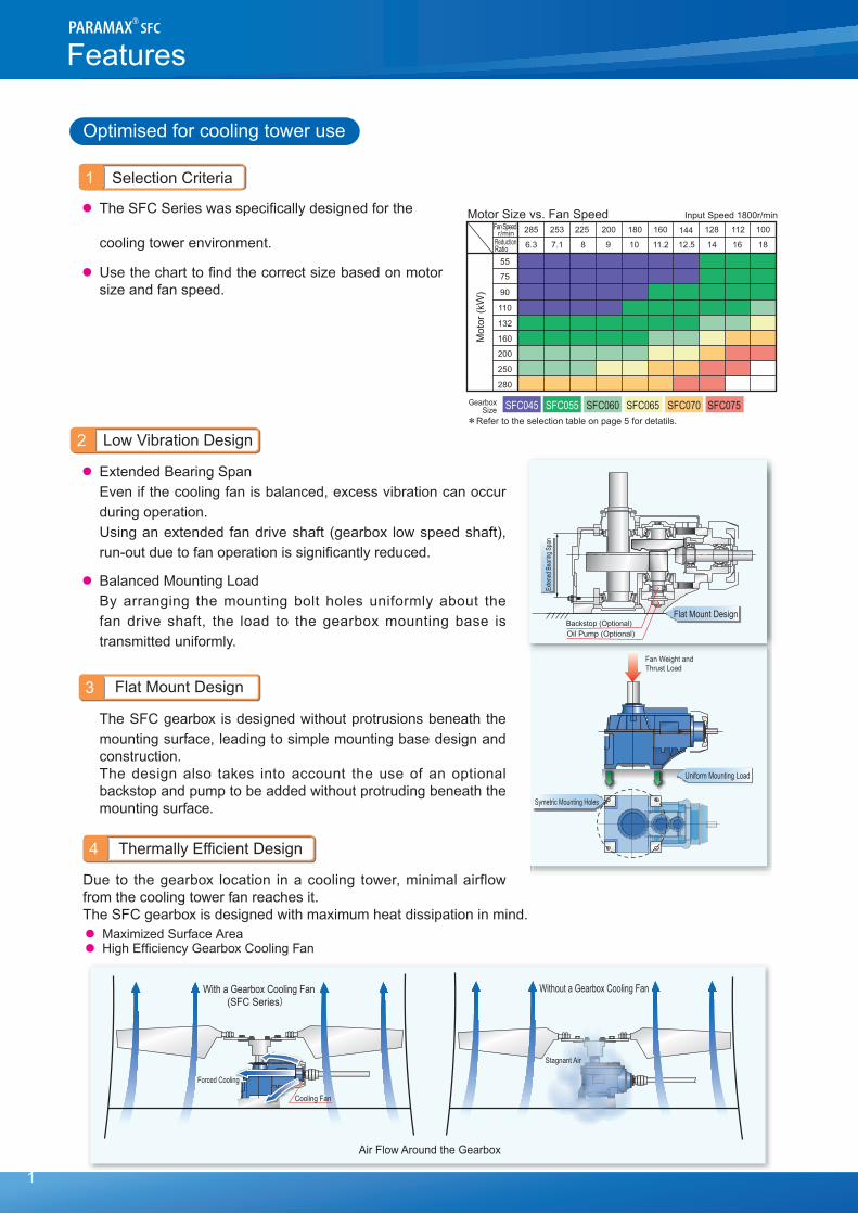
● TheSFCSerieswasspecificallydesignedforthe
cooling tower environment.
● Usethecharttofindthecorrectsizebasedonmotorsizeandfanspeed.
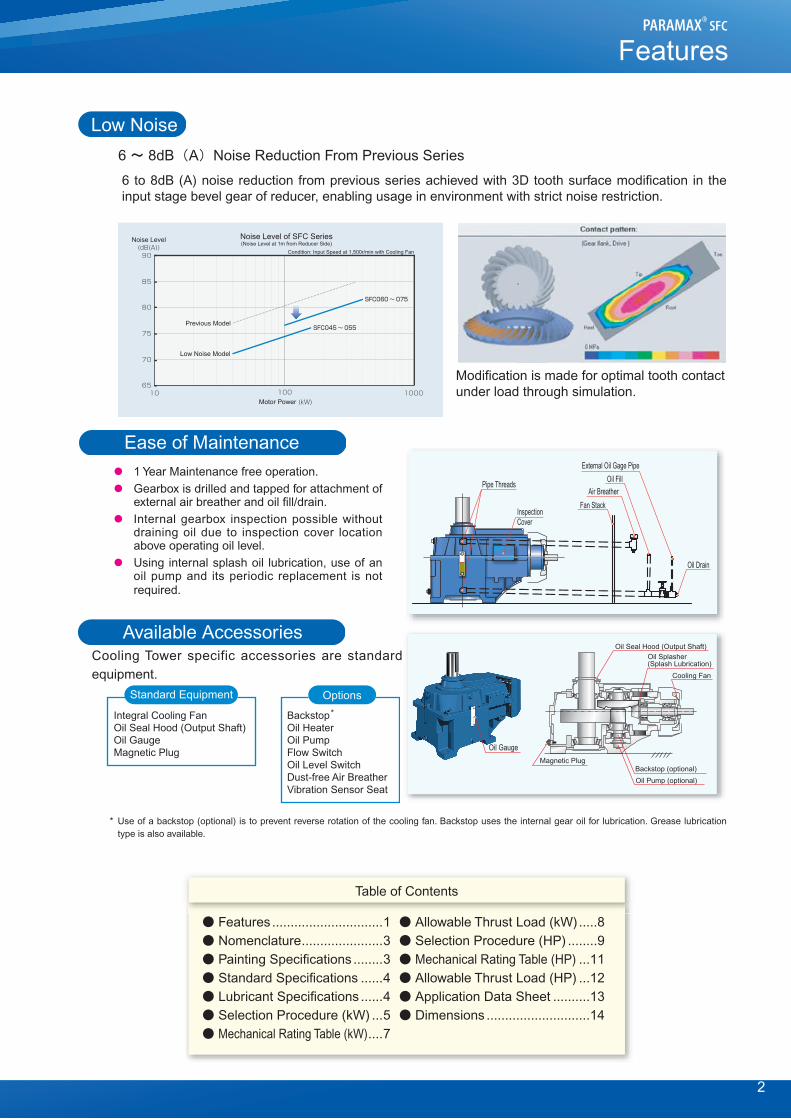
2 Low Vibration Design
● Extended Bearing Span Evenifthecoolingfanisbalanced,excessvibrationcanoccur
during operation. Usinganextendedfandriveshaft (gearbox lowspeedshaft),
run-outduetofanoperationissignificantlyreduced.
● Balanced Mounting Load Byarranging themountingbolt holesuniformlyabout the
fandrive shaft, the load to thegearboxmountingbase istransmitteduniformly.
3 Flat Mount Design
The SFC gearbox is designed without protrusions beneath the mounting surface, leading to simple mounting base design and construction.
The design also takes into account the use of an optional backstop and pump to be added without protruding beneath the mounting surface.
4 Thermally Efficient Design
Due to the gearbox location in a cooling tower, minimal airflow from the cooling tower fan reaches it.The SFC gearbox is designed with maximum heat dissipation in mind.● Maximized Surface Area● High Efficiency Gearbox Cooling Fan
Mot
or (k
W)
Motor Size vs. Fan Speed Input Speed 1800r/min
ReductionRatio
r/minFan Speed
GearboxSize
112 100225 200 180 160 144 128285 253
16 188 9 10 11.2 12.5 146.3 7.1
SFC045 SFC055 SFC060 SFC065 SFC070 SFC075
55
75
90
110
132
160
200
250
280
∗Refer to the selection table on page 5 for detatils.
Backstop (Optional)Oil Pump (Optional)
Flat Mount Design
Exten
ed B
earin
g Spa
n
Fan Weight andThrust Load
Uniform Mounting Load
Symetric Mounting Holes
Air Flow Around the Gearbox
Cooling Fan
Forced Cooling
Stagnant Air
With a Gearbox Cooling Fan (SFC Series)
Without a Gearbox Cooling Fan
Flat Mount Design
Exten
ed B
earin
g Spa
n
Backstop (Optional)Oil Pump (Optional)
2
Low Noise
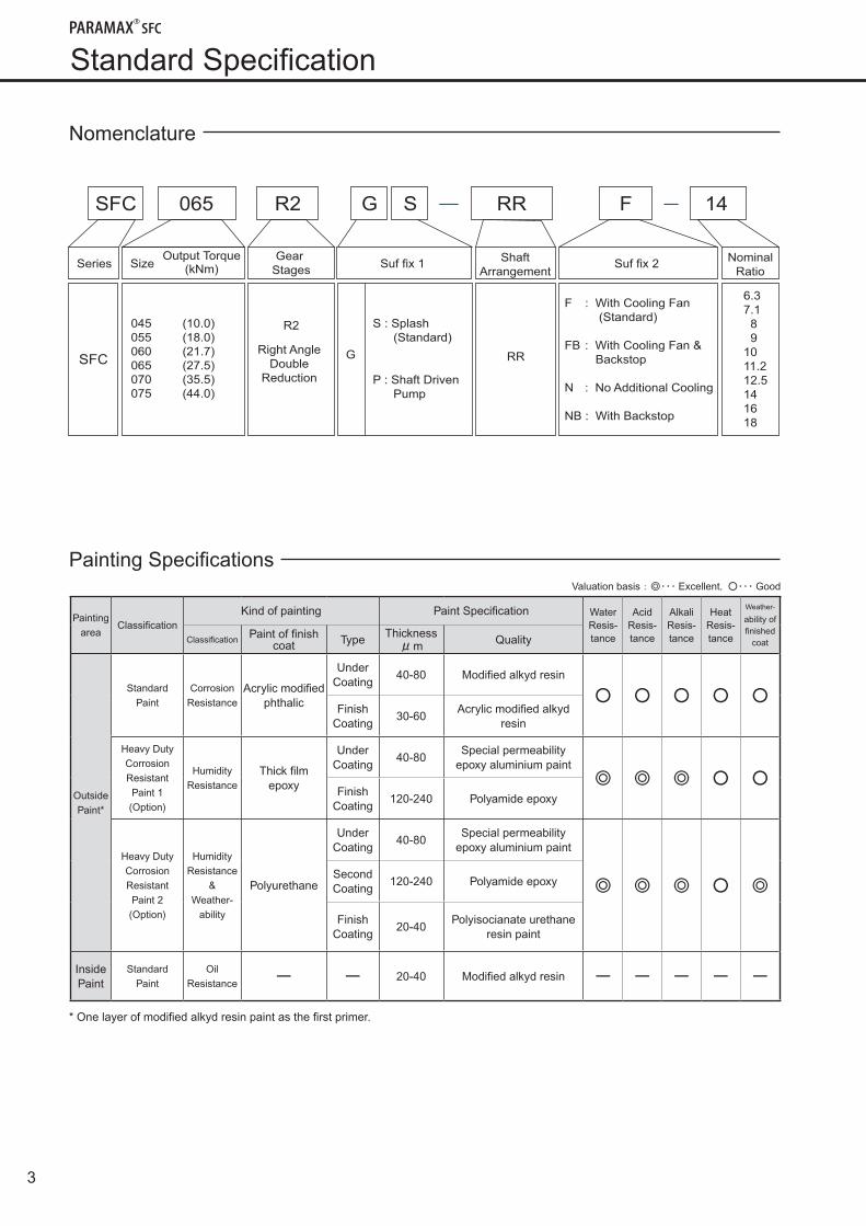
6 ~ 8dB(A)Noise Reduction From Previous Series
6 to 8dB (A) noise reduction from previous series achieved with 3D tooth surface modification in the input stage bevel gear of reducer, enabling usage in environment with strict noise restriction.
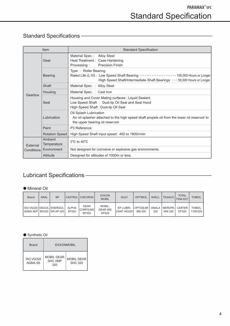
Ease of Maintenance● 1 Year Maintenance free operation. ● Gearbox is drilled and tapped for attachment of
external air breather and oil fill/drain. ● Internal gearbox inspection possible without
draining oil due to inspection cover location above operating oil level.
● Using internal splash oil lubrication, use of an oil pump and its periodic replacement is not required.
Available AccessoriesCooling Tower specific accessories are standard equipment.
* Use of a backstop (optional) is to prevent reverse rotation of the cooling fan. Backstop uses the internal gear oil for lubrication. Grease lubrication type is also available.
Features
Oil FillAir Breather
InspectionCover
Pipe Threads
Oil Drain
External Oil Gage Pipe
Fan Stack
Cooling Fan
Oil Splasher(Splash Lubrication)
Oil Seal Hood (Output Shaft)
Magnetic Plug
Oil Gauge
Backstop (optional)Oil Pump (optional)
Standard Equipment
Integral Cooling Fan
Oil Seal Hood (Output Shaft)
Oil Gauge
Magnetic Plug
Backstop
Oil Heater
Oil Pump
Flow Switch
Oil Level Switch
Dust-free Air Breather
Vibration Sensor Seat
*
Options
Table of Contents
● Features ..............................1 ● Allowable Thrust Load (kW) .....8● Nomenclature ......................3 ● Selection Procedure (HP) ........9● Painting Specifications ........3 ● Mechanical Rating Table (HP) ...11● Standard Specifications ......4 ● Allowable Thrust Load (HP) ...12● Lubricant Specifications ......4 ● Application Data Sheet ..........13● Selection Procedure (kW) ...5 ● Dimensions ............................14● Mechanical Rating Table (kW) ....7
Noise Level of SFC Series(Noise Level at 1m from Reducer Side)
Condition: Input Speed at 1,500r/min with Cooling Fan
Noise Level
Previous Model
Low Noise Model
Motor Power
Modification is made for optimal tooth contact under load through simulation.
3
StandardSpecification
Nomenclature
PaintingSpecificationsValuation basis:◎・・・ Excellent, ○・・・ Good
Paintingarea
ClassificationKind of painting Paint Specification Water
Resis-tance
AcidResis-tance
AlkaliResis-tance
HeatResis-tance
Weather-
ability offinished
coatClassification Paint of finish coat Type Thickness
μm Quality
OutsidePaint*
StandardPaint
CorrosionResistance
Acrylic modified phthalic
UnderCoating
40-80 Modified alkyd resin
○ ○ ○ ○ ○Finish
Coating30-60
Acrylic modified alkyd resin
Heavy DutyCorrosionResistantPaint 1(Option)
HumidityResistance
Thick film epoxy
UnderCoating
40-80Special permeability
epoxy aluminium paint◎ ◎ ◎ ○ ○
Finish Coating
120-240 Polyamide epoxy
Heavy DutyCorrosionResistantPaint 2(Option)
HumidityResistance
&Weather-
ability
Polyurethane
UnderCoating
40-80Special permeability
epoxy aluminium paint
◎ ◎ ◎ ○ ◎Second Coating
120-240 Polyamide epoxy
Finish Coating
20-40Polyisocianate urethane
resin paint
InsidePaint
StandardPaint
OilResistance ー ー 20-40 Modified alkyd resin ー ー ー ー ー
*Onelayerofmodifiedalkydresinpaintasthefirstprimer.
SFC
SeriesGear
StagesSuf fix 1
Shaft
ArrangementSuf fix 2
Nominal
RatioSize
Output Torque(kNm)
R2 S : Splash
(Standard)
P : Shaft Driven
Pump
RRG
6.3
7.1
8
9
10
11.2
12.5
14
16
18
045 (10.0)
055 (18.0)
060 (21.7)
065 (27.5)
070 (35.5)
075 (44.0)
SFC 065 R2 14RRSG F
Right Angle
Double
Reduction
F : With Cooling Fan
(Standard)
FB : With Cooling Fan &
Backstop
N : No Additional Cooling
NB : With Backstop
4
StandardSpecification
Standard Specifications
Item Standard Specification
Gearbox
GearMaterial Spec. : Alloy SteelHeat Treatment : Case HardeningProcessing : Precision Finish
BearingType : Roller BearingRated Life (L10) : Low Speed Shaft Bearing ・・・・・・・・・・・・・・・・・・・・・ 100,000 Hours or Longer
High Speed Shaft/Intermediate Shaft Bearings ・・・ 50,000 Hours or Longer
Shaft Material Spec. : Alloy Steel
Housing Material Spec. : Cast Iron
SealHousing and Cover Mating surfaces : Liquid SealantLow Speed Shaft : Dust-lip Oil Seal and Seal HoodHigh Speed Shaft : Dust-lip Oil Seal
LubricationOil Splash Lubrication
An oil splasher attached to the high speed shaft propels oil from the lower oil reservoir to the upper bearing oil reservoir.
Paint P3 Reference
Rotation Speed High Speed Shaft input speed: 450 to 1800r/min
External Conditions
Ambient Temperature
0℃ to 40℃
Environment Not designed for corrosive or explosive gas environments.
Altitude Designed for altitudes of 1000m or less.
Lubricant Specifications
● Mineral Oil
Brand ARAL BP CASTROL CHEVRONEXXON MOBIL
GULF OPTIMOL SHELL TEXACOTOTAL
FINA ELFTHIBOL
ISO VG320AGMA 6EP
DEGOLBG320
ENERGOLGR-XP-320
ALPHASP320
GEARCOMPOUNS
EP320
MOBIL-GEAR 600
XP320
EP LUBRI-CANT HD320
OPTIGEARBM 320
OMALA320
MEROPAWM 320
CARTEREP320
THIBOL1100/320
● Synthetic Oil
Brand EXXONMOBIL
ISO VG320AGMA 6S
MOBIL GEARSHC XMP
320
MOBIL GEARSHC 320
5
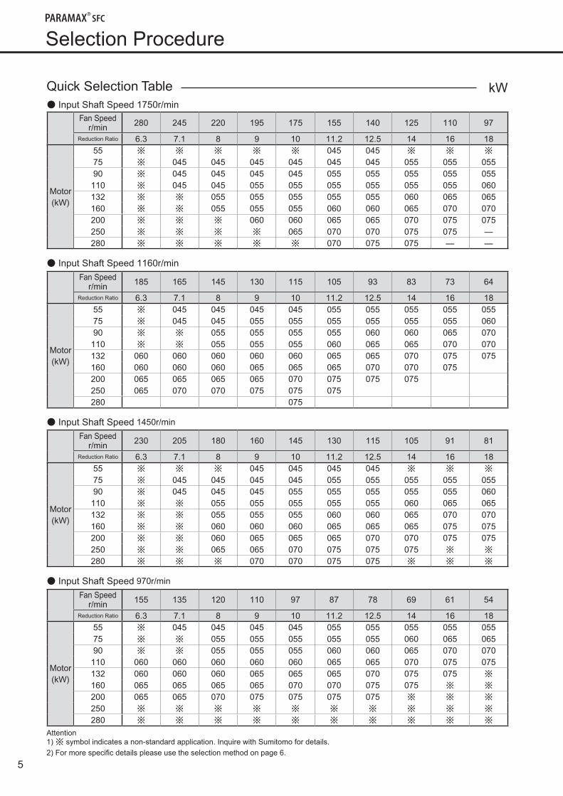
Selection Procedure
Quick Selection Table● Input Shaft Speed 1750r/min
Fan Speed r/min 280 245 220 195 175 155 140 125 110 97
Reduction Ratio 6.3 7.1 8 9 10 11.2 12.5 14 16 18
Motor(kW)
55 ※ ※ ※ ※ ※ 045 045 ※ ※ ※
75 ※ 045 045 045 045 045 045 055 055 05590 ※ 045 045 045 045 055 055 055 055 055110 ※ 045 045 055 055 055 055 055 055 060132 ※ ※ 055 055 055 055 055 060 065 065160 ※ ※ 055 055 055 060 060 065 070 070200 ※ ※ ※ 060 060 065 065 070 075 075250 ※ ※ ※ ※ 065 070 070 075 075 ―
280 ※ ※ ※ ※ ※ 070 075 075 ― ―
● Input Shaft Speed 1160r/minFan Speed
r/min 185 165 145 130 115 105 93 83 73 64
Reduction Ratio 6.3 7.1 8 9 10 11.2 12.5 14 16 18
Motor(kW)
55 ※ 045 045 045 045 055 055 055 055 05575 ※ 045 045 055 055 055 055 055 055 06090 ※ ※ 055 055 055 055 060 060 065 070110 ※ ※ 055 055 055 060 065 065 070 070132 060 060 060 060 060 065 065 070 075 075160 060 060 060 065 065 065 070 070 075200 065 065 065 065 070 075 075 075250 065 070 070 075 075 075280 075
● Input Shaft Speed 1450r/min
Fan Speed r/min 230 205 180 160 145 130 115 105 91 81
Reduction Ratio 6.3 7.1 8 9 10 11.2 12.5 14 16 18
Motor(kW)
55 ※ ※ ※ 045 045 045 045 ※ ※ ※
75 ※ 045 045 045 045 055 055 055 055 05590 ※ 045 045 045 055 055 055 055 055 060110 ※ ※ 055 055 055 055 055 060 065 065132 ※ ※ 055 055 055 060 060 065 070 070160 ※ ※ 060 060 060 065 065 065 075 075200 ※ ※ 060 065 065 065 070 070 075 075250 ※ ※ 065 065 070 075 075 075 ※ ※
280 ※ ※ ※ 070 070 075 075 ※ ※ ※
● Input Shaft Speed 970r/min
Fan Speed r/min 155 135 120 110 97 87 78 69 61 54
Reduction Ratio 6.3 7.1 8 9 10 11.2 12.5 14 16 18
Motor(kW)
55 ※ 045 045 045 045 055 055 055 055 05575 ※ ※ 055 055 055 055 055 060 065 06590 ※ ※ 055 055 055 060 060 065 070 070110 060 060 060 060 060 065 065 070 075 075132 060 060 060 065 065 065 070 075 075 ※
160 065 065 065 065 070 070 075 075 ※ ※
200 065 065 070 075 075 075 075 ※ ※ ※
250 ※ ※ ※ ※ ※ ※ ※ ※ ※ ※
280 ※ ※ ※ ※ ※ ※ ※ ※ ※ ※
Attention1)※ symbolindicatesanon-standardapplication.InquirewithSumitomofordetails.2)Formorespecificdetailspleaseusetheselectionmethodonpage6.
kW
6
kW
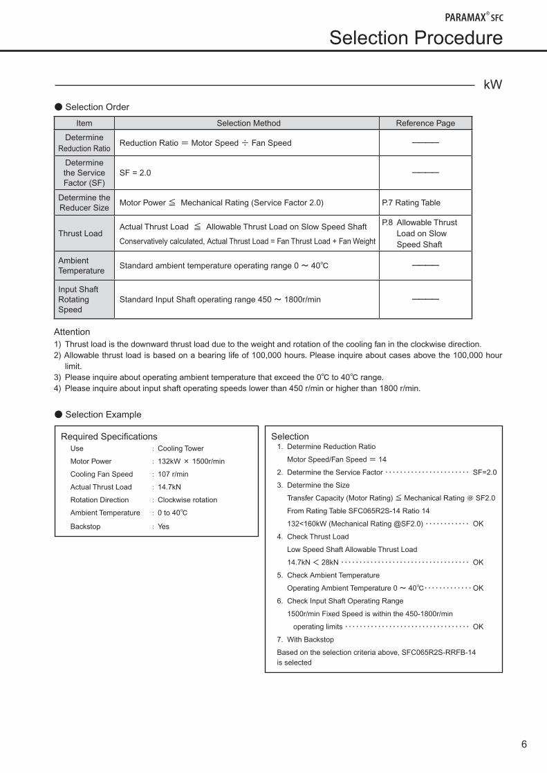
● Selection Order
Item Selection Method Reference Page
Determine Reduction Ratio
Reduction Ratio = Motor Speed ÷ Fan Speed ーーーー
Determine the Service Factor (SF)
SF = 2.0 ーーーー
Determine the Reducer Size
Motor Power ≦ Mechanical Rating (Service Factor 2.0) P.7 Rating Table
Thrust LoadActual Thrust Load ≦ Allowable Thrust Load on Slow Speed Shaft
Conservatively calculated, Actual Thrust Load = Fan Thrust Load + Fan Weight
P.8 Allowable Thrust Load on Slow Speed Shaft
Ambient Temperature
Standard ambient temperature operating range 0 ~ 40℃ ーーーー
Input Shaft Rotating Speed
Standard Input Shaft operating range 450 ~ 1800r/min ーーーー
Attention1) Thrust load is the downward thrust load due to the weight and rotation of the cooling fan in the clockwise direction.2) Allowable thrust load is based on a bearing life of 100,000 hours. Please inquire about cases above the 100,000 hour
limit.3) Please inquire about operating ambient temperature that exceed the 0℃ to 40℃ range.4) Please inquire about input shaft operating speeds lower than 450 r/min or higher than 1800 r/min.
● Selection Example
Selection Procedure
Required SpecificationsUse : Cooling Tower
Motor Power : 132kW × 1500r/min
Cooling Fan Speed : 107 r/min
Actual Thrust Load : 14.7kN
Rotation Direction : Clockwise rotation
Ambient Temperature : 0 to 40℃
Backstop : Yes
Selection1. Determine Reduction Ratio
Motor Speed/Fan Speed = 14
2. Determine the Service Factor ・・・・・・・・・・・・・・・・・・・・・・・ SF=2.0
3. Determine the Size
Transfer Capacity (Motor Rating) ≦ Mechanical Rating @ SF2.0
From Rating Table SFC065R2S-14 Ratio 14
132<160kW (Mechanical Rating @SF2.0) ・・・・・・・・・・・・ OK
4. Check Thrust Load
Low Speed Shaft Allowable Thrust Load
14.7kN < 28kN ・・・・・・・・・・・・・・・・・・・・・・・・・・・・・・・・・・・ OK
5. Check Ambient Temperature
Operating Ambient Temperature 0 ~ 40℃・・・・・・・・・・・・・ OK
6. Check Input Shaft Operating Range
1500r/min Fixed Speed is within the 450-1800r/min
operating limits ・・・・・・・・・・・・・・・・・・・・・・・・・・・・・・・・・・ OK
7. With Backstop
Based on the selection criteria above, SFC065R2S-RRFB-14 is selected
7
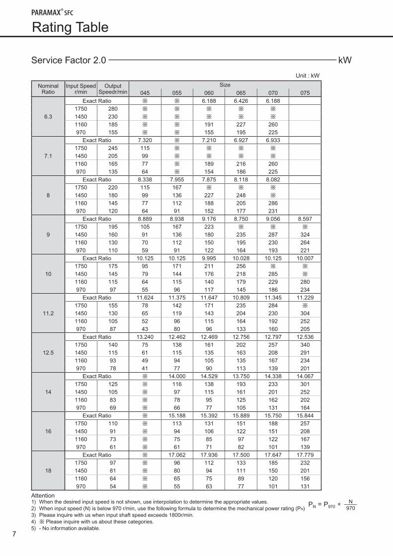
RatingTable
Service Factor 2.0 kW
Unit : kW
NominalRatio
Input Speedr/min
Output Speedr/min
Size045 055 060 065 070 075
6.3
Exact Ratio ※ ※ 6.188 6.426 6.1881750 280 ※ ※ ※ ※ ※
1450 230 ※ ※ ※ ※ ※
1160 185 ※ ※ 191 227 260970 155 ※ ※ 155 195 225
7.1
Exact Ratio 7.320 ※ 7.210 6.927 6.9331750 245 115 ※ ※ ※ ※
1450 205 99 ※ ※ ※ ※
1160 165 77 ※ 189 216 260970 135 64 ※ 154 186 225
8
Exact Ratio 8.338 7.955 7.875 8.118 8.0821750 220 115 167 ※ ※ ※
1450 180 99 136 227 248 ※
1160 145 77 112 188 205 286970 120 64 91 152 177 231
9
Exact Ratio 8.889 8.938 9.176 8.750 9.056 8.5971750 195 105 167 223 ※ ※ ※
1450 160 91 136 180 235 287 3241160 130 70 112 150 195 230 264970 110 59 91 122 164 193 221
10
Exact Ratio 10.125 10.125 9.995 10.028 10.125 10.0071750 175 95 171 211 256 ※ ※
1450 145 79 144 176 218 285 ※
1160 115 64 115 140 179 229 280970 97 55 96 117 145 186 234
11.2
Exact Ratio 11.624 11.375 11.647 10.809 11.345 11.2291750 155 78 142 171 235 284 ※
1450 130 65 119 143 204 230 3041160 105 52 96 115 164 192 252970 87 43 80 96 133 160 205
12.5
Exact Ratio 13.240 12.462 12.469 12.756 12.797 12.5361750 140 75 138 161 202 257 3401450 115 61 115 135 163 208 2911160 93 49 94 105 135 167 234970 78 41 77 90 113 139 201
14
Exact Ratio ※ 14.000 14.529 13.750 14.338 14.0671750 125 ※ 116 138 193 233 3011450 105 ※ 97 115 161 201 2521160 83 ※ 78 95 125 162 202970 69 ※ 66 77 105 131 164
16
Exact Ratio ※ 15.188 15.392 15.889 15.750 15.8441750 110 ※ 113 131 151 188 2571450 91 ※ 94 106 122 151 2081160 73 ※ 75 85 97 122 167970 61 ※ 61 71 82 101 139
18
Exact Ratio ※ 17.062 17.936 17.500 17.647 17.7791750 97 ※ 96 112 133 185 2321450 81 ※ 80 94 111 150 2011160 64 ※ 65 75 89 120 156970 54 ※ 55 63 77 101 131
Attention1) When the desired input speed is not shown, use interpolation to determine the appropriate values.2) When input speed (N) is below 970 r/min, use the following formula to determine the mechanical power rating (PN)3) Please inquire with us when input shaft speed exceeds 1800r/min.4) ※ Please inquire with us about these categories.5) - No information available.
PN = P970 × N970
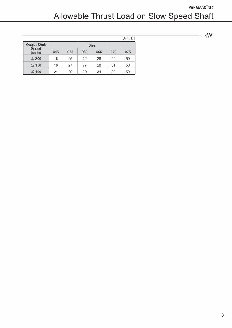
8
kW Unit:kN
Output Shaft Speed(r/min)
Size
045 055 060 065 070 075
≦ 300 16 25 22 28 29 50
≦ 150 18 27 27 28 31 50
≦ 100 21 29 30 34 39 50
AllowableThrustLoadonSlowSpeedShaft
9
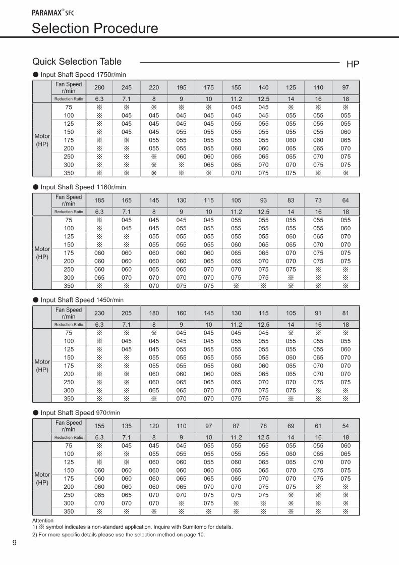
Selection Procedure
Quick Selection Table● Input Shaft Speed 1750r/min
Fan Speed r/min 280 245 220 195 175 155 140 125 110 97
Reduction Ratio 6.3 7.1 8 9 10 11.2 12.5 14 16 18
Motor(HP)
75 ※ ※ ※ ※ ※ 045 045 ※ ※ ※
100 ※ 045 045 045 045 045 045 055 055 055125 ※ 045 045 045 045 055 055 055 055 055150 ※ 045 045 055 055 055 055 055 055 060175 ※ ※ 055 055 055 055 055 060 060 065200 ※ ※ 055 055 055 060 060 065 065 070250 ※ ※ ※ 060 060 065 065 065 070 075300 ※ ※ ※ ※ 065 065 070 070 075 075350 ※ ※ ※ ※ ※ 070 075 075 ※ ※
● Input Shaft Speed 1160r/minFan Speed
r/min 185 165 145 130 115 105 93 83 73 64
Reduction Ratio 6.3 7.1 8 9 10 11.2 12.5 14 16 18
Motor(HP)
75 ※ 045 045 045 045 055 055 055 055 055100 ※ 045 045 055 055 055 055 055 055 060125 ※ ※ 055 055 055 055 055 060 065 070150 ※ ※ 055 055 055 060 065 065 070 070175 060 060 060 060 060 065 065 070 075 075200 060 060 060 060 065 065 070 070 075 075250 060 060 065 065 070 070 075 075 ※ ※
300 065 070 070 070 070 075 075 ※ ※ ※
350 ※ ※ 070 075 075 ※ ※ ※ ※ ※
● Input Shaft Speed 1450r/min
Fan Speed r/min 230 205 180 160 145 130 115 105 91 81
Reduction Ratio 6.3 7.1 8 9 10 11.2 12.5 14 16 18
Motor(HP)
75 ※ ※ ※ 045 045 045 045 ※ ※ ※
100 ※ 045 045 045 045 055 055 055 055 055125 ※ 045 045 055 055 055 055 055 055 060150 ※ ※ 055 055 055 055 055 060 065 070175 ※ ※ 055 055 055 060 060 065 070 070200 ※ ※ 060 060 060 065 065 065 070 070250 ※ ※ 060 065 065 065 070 070 075 075300 ※ ※ 065 065 070 070 075 075 ※ ※
350 ※ ※ ※ 070 070 075 075 ※ ※ ※
● Input Shaft Speed 970r/min
Fan Speed r/min 155 135 120 110 97 87 78 69 61 54
Reduction Ratio 6.3 7.1 8 9 10 11.2 12.5 14 16 18
Motor(HP)
75 ※ 045 045 045 055 055 055 055 055 060100 ※ ※ 055 055 055 055 055 060 065 065125 ※ ※ 060 060 055 060 065 065 070 070150 060 060 060 060 060 065 065 070 075 075175 060 060 060 065 065 065 070 070 075 075200 060 060 060 065 070 070 075 075 ※ ※
250 065 065 070 070 075 075 075 ※ ※ ※
300 070 070 070 ※ 075 ※ ※ ※ ※ ※
350 ※ ※ ※ ※ ※ ※ ※ ※ ※ ※
Attention1)※ symbolindicatesanon-standardapplication.InquirewithSumitomofordetails.2)Formorespecificdetailspleaseusetheselectionmethodonpage10.
HP
10
HP
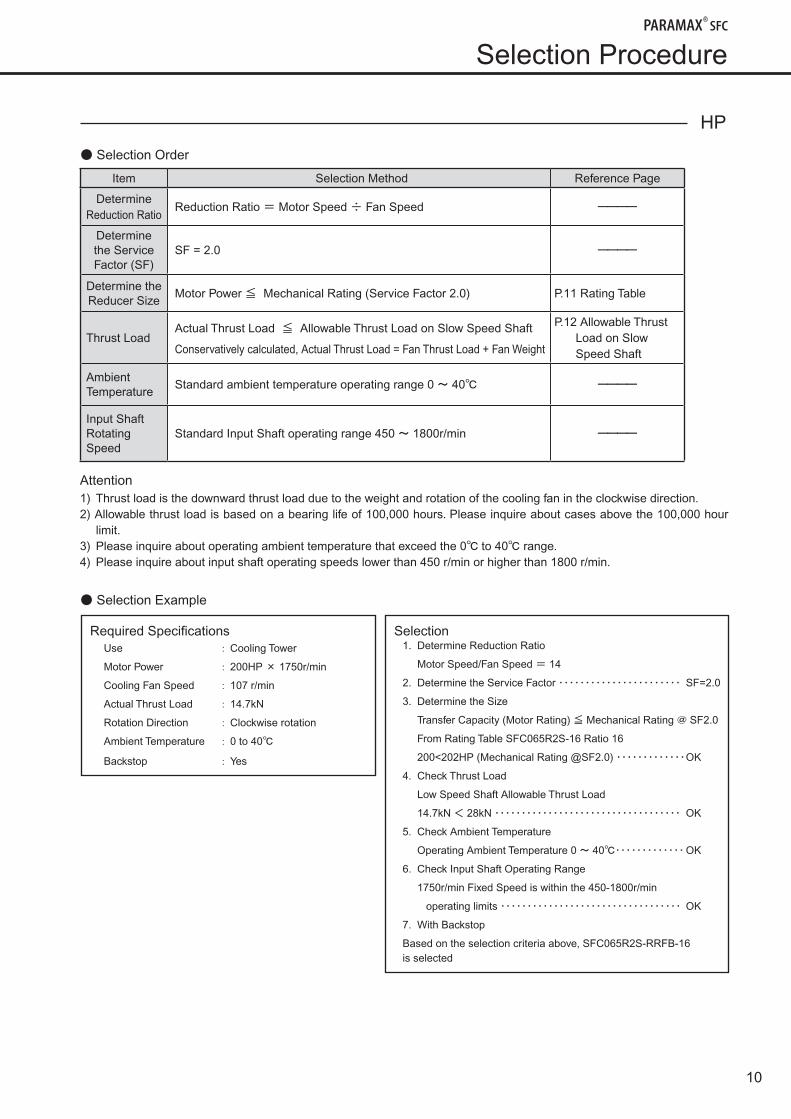
● Selection Order
Item Selection Method Reference Page
Determine Reduction Ratio
Reduction Ratio = Motor Speed ÷ Fan Speed ーーーー
Determine the Service Factor (SF)
SF = 2.0 ーーーー
Determine the Reducer Size
Motor Power ≦ Mechanical Rating (Service Factor 2.0) P.11 Rating Table
Thrust LoadActual Thrust Load ≦ Allowable Thrust Load on Slow Speed Shaft
Conservatively calculated, Actual Thrust Load = Fan Thrust Load + Fan Weight
P.12 Allowable Thrust Load on Slow Speed Shaft
Ambient Temperature
Standard ambient temperature operating range 0 ~ 40℃ ーーーー
Input Shaft Rotating Speed
Standard Input Shaft operating range 450 ~ 1800r/min ーーーー
Attention1) Thrust load is the downward thrust load due to the weight and rotation of the cooling fan in the clockwise direction.2) Allowable thrust load is based on a bearing life of 100,000 hours. Please inquire about cases above the 100,000 hour
limit.3) Please inquire about operating ambient temperature that exceed the 0℃ to 40℃ range.4) Please inquire about input shaft operating speeds lower than 450 r/min or higher than 1800 r/min.
● Selection Example
Selection Procedure
Required SpecificationsUse : Cooling Tower
Motor Power : 200HP × 1750r/min
Cooling Fan Speed : 107 r/min
Actual Thrust Load : 14.7kN
Rotation Direction : Clockwise rotation
Ambient Temperature : 0 to 40℃
Backstop : Yes
Selection1. Determine Reduction Ratio
Motor Speed/Fan Speed = 14
2. Determine the Service Factor ・・・・・・・・・・・・・・・・・・・・・・・ SF=2.0
3. Determine the Size
Transfer Capacity (Motor Rating) ≦ Mechanical Rating @ SF2.0
From Rating Table SFC065R2S-16 Ratio 16
200<202HP (Mechanical Rating @SF2.0) ・・・・・・・・・・・・・ OK
4. Check Thrust Load
Low Speed Shaft Allowable Thrust Load
14.7kN < 28kN ・・・・・・・・・・・・・・・・・・・・・・・・・・・・・・・・・・・ OK
5. Check Ambient Temperature
Operating Ambient Temperature 0 ~ 40℃・・・・・・・・・・・・・ OK
6. Check Input Shaft Operating Range
1750r/min Fixed Speed is within the 450-1800r/min
operating limits ・・・・・・・・・・・・・・・・・・・・・・・・・・・・・・・・・・ OK
7. With Backstop
Based on the selection criteria above, SFC065R2S-RRFB-16 is selected
11
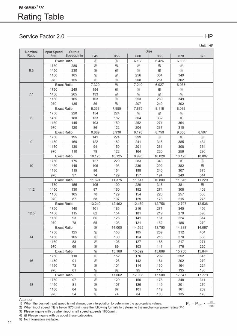
RatingTable
Service Factor 2.0 HP
Unit : HP
NominalRatio
Input Speedr/min
Output Speedr/min
Size045 055 060 065 070 075
6.3
Exact Ratio ※ ※ 6.188 6.426 6.1881750 280 ※ ※ ※ ※ ※
1450 230 ※ ※ ※ ※ ※
1160 185 ※ ※ 256 304 349970 155 ※ ※ 208 261 302
7.1
Exact Ratio 7.320 ※ 7.210 6.927 6.9331750 245 154 ※ ※ ※ ※
1450 205 133 ※ ※ ※ ※
1160 165 103 ※ 253 289 349970 135 86 ※ 207 249 302
8
Exact Ratio 8.338 7.955 7.875 8.118 8.0821750 220 154 224 ※ ※ ※
1450 180 133 182 304 332 ※
1160 145 103 150 252 274 354970 120 86 122 204 237 310
9
Exact Ratio 8.889 8.938 9.176 8.750 9.056 8.5971750 195 141 224 299 ※ ※ ※
1450 160 122 182 241 315 385 4341160 130 94 150 201 261 308 354970 110 79 122 164 220 259 296
10
Exact Ratio 10.125 10.125 9.995 10.028 10.125 10.0071750 175 127 229 283 343 ※ ※
1450 145 106 193 236 292 382 ※
1160 115 86 154 188 240 307 375970 97 74 129 157 194 249 314
11.2
Exact Ratio 11.624 11.375 11.647 10.809 11.345 11.2291750 155 105 190 229 315 381 ※
1450 130 87 160 192 274 308 4081160 105 70 129 154 220 257 338970 87 58 107 129 178 215 275
12.5
Exact Ratio 13.240 12.462 12.469 12.756 12.797 12.5361750 140 101 185 216 271 345 4561450 115 82 154 181 219 279 3901160 93 66 126 141 181 224 314970 78 55 103 121 152 186 270
14
Exact Ratio ※ 14.000 14.529 13.750 14.338 14.0671750 125 ※ 156 185 259 312 4041450 105 ※ 130 154 216 270 3381160 83 ※ 105 127 168 217 271970 69 ※ 89 103 141 176 220
16
Exact Ratio ※ 15.188 15.392 15.889 15.750 15.8441750 110 ※ 152 176 202 252 3451450 91 ※ 126 142 164 202 2791160 73 ※ 101 114 130 164 224970 61 ※ 82 95 110 135 186
18
Exact Ratio ※ 17.062 17.936 17.500 17.647 17.7791750 97 ※ 129 150 178 248 3111450 81 ※ 107 126 149 201 2701160 64 ※ 87 101 119 161 209970 54 ※ 74 84 103 135 176
Attention1) When the desired input speed is not shown, use interpolation to determine the appropriate values.2) When input speed (N) is below 970 r/min, use the following formula to determine the mechanical power rating (PN)3) Please inquire with us when input shaft speed exceeds 1800r/min.4) ※ Please inquire with us about these categories.5) No information available.
PN = P970 × N970
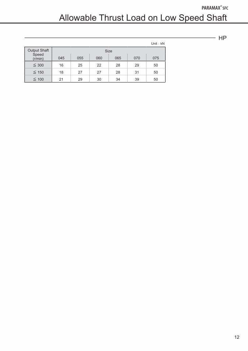
12
AllowableThrustLoadonLowSpeedShaft
HP Unit:kN
Output Shaft Speed(r/min)
Size
045 055 060 065 070 075
≦ 300 16 25 22 28 29 50
≦ 150 18 27 27 28 31 50
≦ 100 21 29 30 34 39 50
13
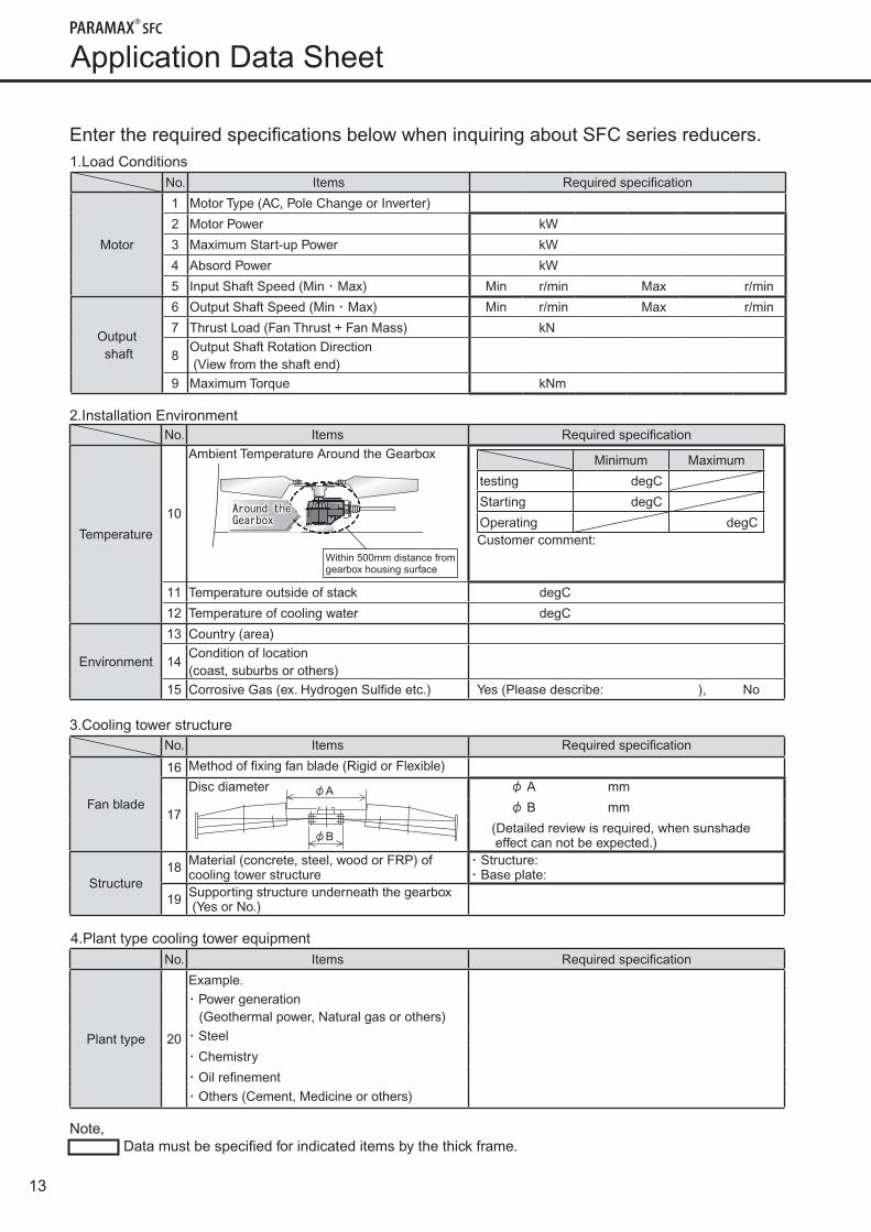
Application Data Sheet
Note, Data must be specified for indicated items by the thick frame.
EntertherequiredspecificationsbelowwheninquiringaboutSFCseriesreducers.1.Load Conditions
No. Items Required specification
Motor
1 Motor Type (AC, Pole Change or Inverter)
2 Motor Power kW
3 Maximum Start-up Power kW
4 Absord Power kW
5 Input Shaft Speed (Min ・ Max) Min r/min Max r/min
Output shaft
6 Output Shaft Speed (Min ・ Max) Min r/min Max r/min
7 Thrust Load (Fan Thrust + Fan Mass) kN
8Output Shaft Rotation Direction (View from the shaft end)
9 Maximum Torque kNm
4.Plant type cooling tower equipmentNo. Items Required specification
Plant type 20
Example.・ Power generation (Geothermal power, Natural gas or others)・ Steel
・ Chemistry
・ Oil refinement・ Others (Cement, Medicine or others)
2.Installation EnvironmentNo. Items Required specification
Temperature
10
Ambient Temperature Around the Gearbox
Customer comment:
11 Temperature outside of stack degC
12 Temperature of cooling water degC
Environment
13 Country (area)
14Condition of location(coast, suburbs or others)
15 Corrosive Gas (ex. Hydrogen Sulfide etc.) Yes (Please describe: ), No
Around the Gearbox
Within 500mm distance fromgearbox housing surface
Minimum Maximum
testing degC
Starting degC
Operating degC
3.Cooling tower structure
φA
φB
No. Items Required specification
Fan blade
16 Method of fixing fan blade (Rigid or Flexible)
17
Disc diameter φ A mm
φ B mm
(Detailed review is required, when sunshade effect can not be expected.)
Structure18 Material (concrete, steel, wood or FRP) of
cooling tower structure・ Structure: ・ Base plate:
19 Supporting structure underneath the gearbox (Yes or No.)
14
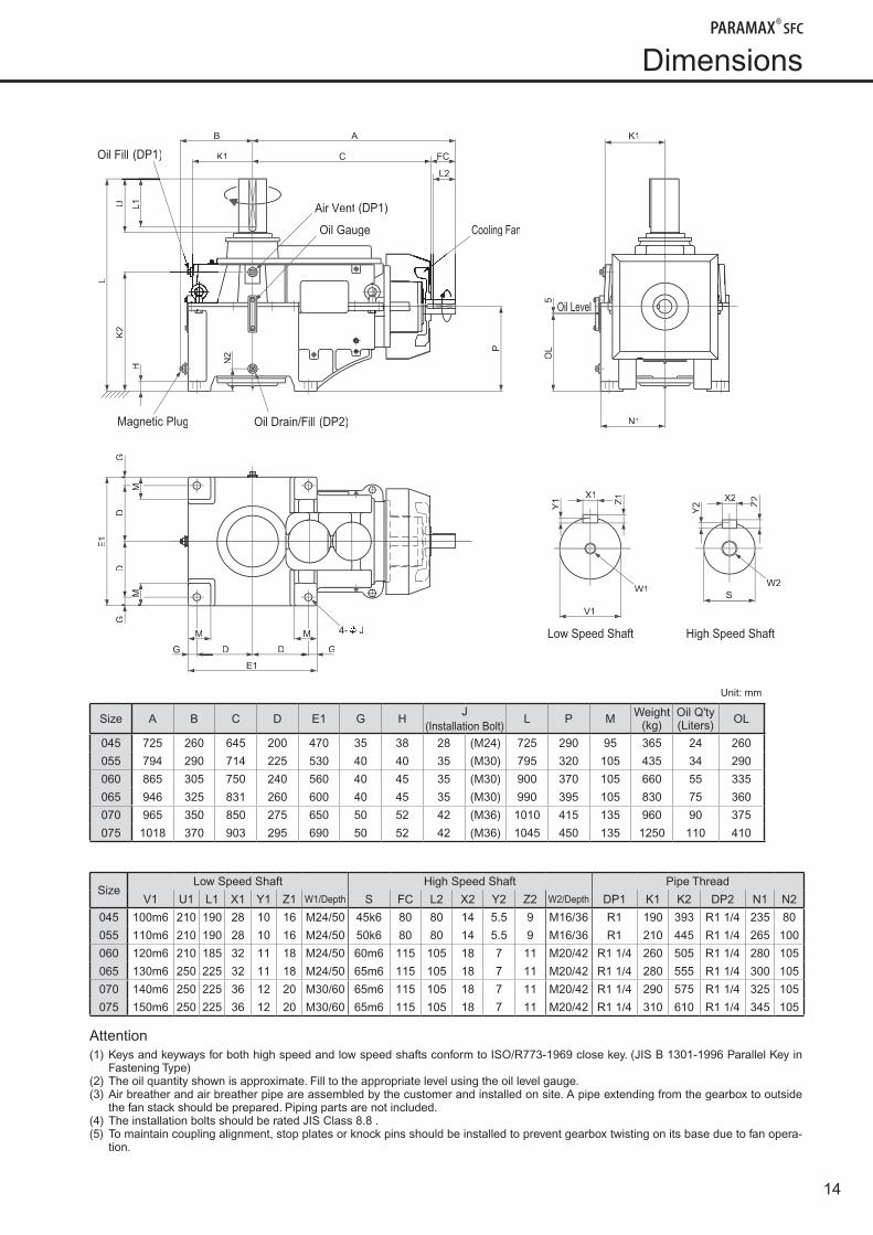
Dimensions
Low Speed Shaft
W1
V1
X1
Z1
Y1
W2
High Speed Shaft
X2
Z2
Z
Y2
S
4- J
(DP2)Oil Drain/Fill
(DP1)Oil Fill
Magnetic Plug
(DP1)Air Vent
Oil Gauge Cooling Fan
B A
L2
P
L1U
L
K2
H
N2
K1
OL
5
N1
M
GG
E1
M M
E1
D D G
DD
FCCK1
Unit: mm
Size A B C D E1 G HJ
(Installation Bolt)L P M Weight
(kg)Oil Q'ty(Liters) OL
045 725 260 645 200 470 35 38 28 (M24) 725 290 95 365 24 260
055 794 290 714 225 530 40 40 35 (M30) 795 320 105 435 34 290
060 865 305 750 240 560 40 45 35 (M30) 900 370 105 660 55 335
065 946 325 831 260 600 40 45 35 (M30) 990 395 105 830 75 360
070 965 350 850 275 650 50 52 42 (M36) 1010 415 135 960 90 375
075 1018 370 903 295 690 50 52 42 (M36) 1045 450 135 1250 110 410
SizeLow Speed Shaft High Speed Shaft Pipe Thread
V1 U1 L1 X1 Y1 Z1 W1/Depth S FC L2 X2 Y2 Z2 W2/Depth DP1 K1 K2 DP2 N1 N2
045 100m6 210 190 28 10 16 M24/50 45k6 80 80 14 5.5 9 M16/36 R1 190 393 R1 1/4 235 80
055 110m6 210 190 28 10 16 M24/50 50k6 80 80 14 5.5 9 M16/36 R1 210 445 R1 1/4 265 100
060 120m6 210 185 32 11 18 M24/50 60m6 115 105 18 7 11 M20/42 R1 1/4 260 505 R1 1/4 280 105
065 130m6 250 225 32 11 18 M24/50 65m6 115 105 18 7 11 M20/42 R1 1/4 280 555 R1 1/4 300 105
070 140m6 250 225 36 12 20 M30/60 65m6 115 105 18 7 11 M20/42 R1 1/4 290 575 R1 1/4 325 105
075 150m6 250 225 36 12 20 M30/60 65m6 115 105 18 7 11 M20/42 R1 1/4 310 610 R1 1/4 345 105
Attention(1) Keys and keyways for both high speed and low speed shafts conform to ISO/R773-1969 close key. (JIS B 1301-1996 Parallel Key in
Fastening Type)(2) The oil quantity shown is approximate. Fill to the appropriate level using the oil level gauge.(3) Air breather and air breather pipe are assembled by the customer and installed on site. A pipe extending from the gearbox to outside
the fan stack should be prepared. Piping parts are not included.(4) The installation bolts should be rated JIS Class 8.8 .(5) To maintain coupling alignment, stop plates or knock pins should be installed to prevent gearbox twisting on its base due to fan opera-
tion.
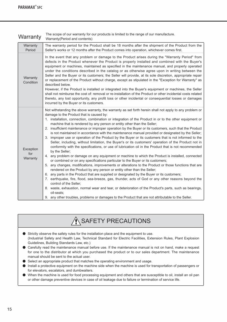
WarrantyPeriod
Thewarrantyperiod for theProductshallbe18monthsafter theshipmentof theProduct fromtheSeller'sworksor12monthsaftertheProductcomesintooperation,whichevercomesfirst.
WarrantyCondition
In theevent thatanyproblemordamage to theProductarisesduring the"WarrantyPeriod" fromdefects in theProductwhenever theProduct isproperly installedandcombinedwith theBuyer'sequipmentormachines,maintainedasspecified in themaintenancemanual,andproperlyoperatedunder theconditionsdescribed in thecatalogorasotherwiseagreeupon inwritingbetween theSellerandtheBuyeror itscustomers;theSellerwillprovide,at itssolediscretion,appropriaterepairorreplacementoftheProductwithoutcharge,exceptasstipulatedinthe"ExceptionforWarranty"asdescribedbelow.However, if theProduct is installedor integrated intotheBuyer'sequipmentormachines, theSellershallnotreimbursethecostof:removalorre-installationoftheProductorotherincidentalcostsrelatedthereto,any lostopportunity,anyprofit lossorother incidentalorconsequential lossesordamagesincurredbytheBuyeroritscustomers.
Exception for
Warranty
Notwithstandingtheabovewarranty,thewarrantyassetforthhereinshallnotapplytoanyproblemordamagetotheProductthatiscausedby:1. installation,connection,combinationor integrationof theProduct inor to theotherequipmentor
machinethatisrenderedbyanypersonorentityotherthantheSeller;2. insufficientmaintenanceorimproperoperationbytheBuyeroritscustomers,suchthattheProduct
isnotmaintainedinaccordancewiththemaintenancemanualprovidedordesignatedbytheSeller;3. improperuseoroperationoftheProductbytheBuyeroritscustomersthatisnotinformedtothe
Seller, including,without limitation, theBuyer'sor itscustomers'operationof theProductnot inconformitywiththespecifications,oruseoflubricationoilintheProductthatisnotrecommendedbytheSeller;
4. anyproblemordamageonanyequipmentormachinetowhichtheProductisinstalled,connectedorcombinedoronanyspecificationsparticulartotheBuyeroritscustomers;
5. anychanges,modifications,improvementsoralterationstotheProductorthosefunctionsthatarerenderedontheProductbyanypersonorentityotherthantheSeller;
6. anypartsintheProductthataresuppliedordesignatedbytheBuyeroritscustomers;7. earthquake, fire, flood,sea-breeze,gas, thunder,actsofGodoranyother reasonsbeyondthe
controloftheSeller;8. waste,exhaustion,normalwearandtear,ordeteriorationoftheProduct'sparts,suchasbearings,
oil-seals;9. anyothertroubles,problemsordamagestotheProductthatarenotattributabletotheSeller.
Warranty
SAFETYPRECAUTIONS
● Strictlyobservethesafetyrulesfortheinstallationplaceandtheequipmenttouse. (IndustrialSafetyandHealthLaw,TechnicalStandardforElectricFacilities,ExtensionRules,PlantExplosion
Guidelines,BuildingStandardsLaw,etc.)● Carefullyreadthemaintenancemanualbeforeuse.Ifthemaintenancemanualisnotonhand,makearequest
forone to thedistributoratwhichyoupurchased theproductor tooursalesdepartment.Themaintenancemanualshouldbesenttotheactualuser.
● Select an appropriate product that matches the operating environment and usage.● Installaprotectiveequipmentonthemachinesidewhenthemachineisusedfortransportationofpassengersor
forelevators,escalators,anddumbwaiters.● Whenthemachineisusedforfoodprocessingequipmentandothersthataresusceptibletooil,installanoilpan
orotherdamagepreventivedevicesincaseofoilleakageduetofailureorterminationofservicelife.
15
Thescopeofourwarrantyforourproductsislimitedtotherangeofourmanufacture.Warranty(Periodandcontents)