Embed Size (px)
DESCRIPTION
PCCHIPS ECS Manual
Citation preview
i
Motherboard User’s Guide
This publication, including photographs, illustrations and software, is under theprotection of international copyright laws, with all rights reserved. Neither thisguide, nor any of the material contained herein, may be reproduced without theexpress written consent of the manufacturer.The information in this document is subject to change without notice. Themanufacturer makes no representations or warranties with respect to thecontents hereof and specifically disclaims any implied warranties of merchant-ability or fitness for any particular purpose. Further, the manufacturer reservesthe right to revise this publication and to make changes from time to time in thecontent hereof without obligation of the manufacturer to notify any person ofsuch revision or changes.
TrademarksIBM, VGA, and PS/2 are registered trademarks of International BusinessMachines.AMD AthlonTM 64 X2 Dual-Core/ Athlon 64TM/ SempronTM are registeredtrademarks of Advanced Micro Devices Inc.Microsoft, MS-DOS and Windows XP/7 are registered trademarks of MicrosoftCorporation.AMI is a registered trademark of American Megatrends Inc.Other names used in this publication may be trademarks and are acknowledged.
Static Electricity Precautions1. Don’t take this motherboard and components out of their original static-
proof package until you are ready to install them.2. While installing, please wear a grounded wrist strap if possible. If you
don’t have a wrist strap, discharge static electricity by touching the baremetal of the system chassis.
3. Carefully hold this motherboard by its edges. Do not touch thosecomponents unless it is absolutely necessary. Put this motherboard onthe top of static-protection package with component side facing upwhile installing.
Pre-Installation Inspection1. Inspect this motherboard whether there are any damages to components
and connectors on the board.2. If you suspect this motherboard has been damaged, do not connect
power to the system. Contact your motherboard vendor about thosedamages.
Copyright © 2010All Rights Reserved
A41G Series, V1.0July, 2010

ii
Motherboard User’s Guide
Table of Contents
Trademark ............................................................................................................ i
Chapter 1: Introduction ..................................................................................... 1Key Features .................................................................................................................... 1Package Contents ........................................................................................................... 4
Chapter 2: Motherboard Installation .............................................................. 5I/O Ports .......................................................................................................................... 5Motherboard Components.................................................................................. 6Installing the Processor ................................................................................................. 7Installing Memory Modules .......................................................................................... 8Jumper Settings ............................................................................................................ 10Install the Motherboard ............................................................................................... 11Connecting Optional Devices ..................................................................................... 12Install Other Devices .................................................................................................... 15Expansion Slots ............................................................................................................ 16
Chapter 3: BIOS Setup Utility ....................................................................... 18Introduction .................................................................................................................. 18Running the Setup Utility...................................................................................18Standard CMOS Setup Page ....................................................................................... 19Advanced Setup Page .................................................................................................. 20Advanced Chipset Setup Page .................................................................................... 21Integrated Peripherals Page ....................................................................................... 22Power Management Setup Page ................................................................................ 23PCI/Plug Setup Page ................................................................................................... 24PC Health Status Page ................................................................................................ 25Frequency/Voltage Control Page ............................................................................... 28Load Default Settings ................................................................................................... 28Supervisor Password Page .......................................................................................... 29User Password Page .................................................................................................... 29Save & Exit Setup ......................................................................................................... 30Exit Without Saving ...................................................................................................... 30
Chapter 4: Software & Applications .............................................................. 31Introduction .................................................................................................................. 31Installing Support Software ........................................................................................ 31Bundled Software Installation .................................................................................... 33
Chapter 5: Setting Up AMD SB700 RAID Configuration ........................... 34Setting Up a bootable RAID Array ............................................................................ 34

iii
Motherboard User’s Guide
Notice:1. Owing to Microsoft’s certifying schedule is various to every supplier, we
might have some drivers not certified yet by Microsoft. Therefore, itmight happen under Windows XP that a dialogue box (shown as below)pops out warning you this software has not passed Windows Logotesting to verify its compatibility with Windows XP. Please rest assuredthat our RD department has already tested and verified these drivers.Just click the “Continue Anyway” button and go ahead the installation.
2. USB 2.0 Driver Limitations:2-1. The USB 2.0 driver only supports Windows XP and Windows 2000.2-2. If you connect a USB 2.0 hub to the root hub, plugging USB devices
into this hub, the system might not successfully execute certain USBdevices’ connection because it could not recognize these devices.
Currently, we are working on such limitations’ solution. As soon as theolution is done, the updated USB drive will be released to our website:www.pcchips.com for your downloading.
Chapter 6: Trouble Shooting Tips ................................................................. 41Start up problems during assemly .............................................................................. 41Start up problems after prolong use .......................................................................... 42Maintenance and care tips .......................................................................................... 42
1
Motherboard User’s Guide
Chapter 1 IntroductionThis motherboard is a high performance, enhanced function motherboard that sup-ports socket AM3 for AMD PhenomTM II processor/Athlon II/Sempron proces-sors for high-end business or personal desktop markets.
The motherboard incorporates the AMD 740G (RS740) Northbridge (NB) andSB700 Southbridge (SB) chipsets. The Northbridge supports the HyperTransportTM
1.0 interface. It supports two DDR3 slots with maximum memory size of 8 GB.One PCI Express x16 slot, intended for Graphics Interface, is fully compliant to thePCI Express Base Specification Revision 1.1.
The SB700 Southbridge supports two PCI slots which are PCI 2.3 compliant. Inaddition, one PCI Express x1 slot is supported, fully compliant to the PCI ExpressBase Specification, Revision 1.1. It integrates USB 2.0 interface, supporting up toeight functional ports (four USB ports and two USB 2.0 headers support addi-tional four USB ports). One onboard IDE connector supports two IDE devices inUltra ATA 133/100/66/33 modes. The Southbridge integrates a Serial ATA hostcontroller, supporting four SATA ports with maximum transfer rate up to 3.0 Gb/s each. It provides AMD SATA RAID configuration with RAID 0, 1 and 10 modessupported.
There is an advanced full set of I/O ports in the rear panel, including PS/2 mouse andkeyboard connectors, one VGA port, one optional DVI port, four USB ports, oneLAN port and audio jacks for microphone, line-in and line-out.
This motherboard is a Micro ATX size motherboard and has power connectors foran ATX power supply.
Key FeaturesThe key features of this motherboard include:
Socket-AM2 Processor Support• Supports AM3 for AMD PhenomTM II processor/Athlon II/Sempron
processors
2
Motherboard User’s Guide
ChipsetThere are AMD740G Northbridge and SB700 Southbridge in this chipset in accor-dance with an innovative and scalable architecture with proven reliability and per-formance.
• One x4 A-Link Express II interface (PCI Express 1.1 compliant) forconnection to an AMD Southbridge
• Supports one PCI Express x16 for Graphics Interface, fully compliant tothe PCI Express Base Specification revision 1.1
• Fully supports ACPI states S0, S1,S2, S3, S4, and S5• Single chip solution in 80nm, 1.2 V CMOS technology• Compliant with PCI 2.3 specification at 33 MHz• Supports four Serial ATA devices which speeds up to 3.0 Gb/s• Integrated USB 2.0 Host Controller supporting up to eight USB 2.0 ports• Integrated IDE controller supports Ultra ATA 133/100/66/33 modes• Supports integrated RAID0, RAID1, and RAID 10 (requires use of 4 or
more SATA ports) functionalities across all 6 ports
Memory Support• Two 240-pin DIMM sockets for DDR SDRAM memory modules• Supports DDR3 1333/1066 memory bus• Maximum installed memory is 8 GB
Expansion Slots• One PCI Express x1 slot• One PCI Express x16 slot• Two 32-bit PCI slots for PCI 2.3 compliant bus interface
Onboard IDE channels• Two IDE Connectors• Supports PIO (Programmable Input/Output) and DMA (Direct Memory
Access) modes• Supports IDE Ultra DMA bus mastering with transfer rates of 133/100/66
MB/sec
Serial ATA• Four Serial ATA Connectors• Transfer rate exceeding best ATA (~1.5 Gb/s) with scalability to higher
rates• Low pin count for both host and devices
3
Chapter 1: Introduction
Audio (VIA VT1705 CODEC)
• 5.1 Channel High Definition Audio Codec• Exceeds Microsoft Windows Logo Program (WLP) Requirements• ADCs support 44.1K/48K/88.2K/96K/192KHz sample rate• Power Support: Digital: 3.3V; Analog: 5.0V
Onboard I/O Ports• Two PS/2 ports for mouse and keyboard• One optional DVI port• One VGA port• Four back-panel USB2.0 ports• One LAN port (optional)• Audio jacks for microphone, line-in and line-out
Fast Ethernet LAN (optional)• Supports PCI ExpressTM 1.1• Integrated 10/100/1000 transceiver• Wake-on-LAN and remote wake-up support
• Supports PCI ExpressTM 1.1• Integrated 10/100 transceiver• Wake-on-LAN and remote wake-up support
USB 2.0• Compliant with Universal Serial Bus Specification Revision 2.0• Compliant with Intel’s Enhanced Host Controller Interface Specification
Revision 1.0• Compliant with Universal Host Controller Interface Specification Revi-
sion 1.1• PCI multi-function device consists of two UHCI Host Controller cores
for full-/low-speed signaling and one EHCI Host Controller core for high-speed signaling
• Root hub consists 4 downstream facing ports with integrated physicallayer transceivers shared by UHCI and EHCI Host Controller, up to eightfunctional ports
• Support PCI-Bus Power Management Interface Specification release 1.1• Legacy support for all downstream facing ports
4
Motherboard User’s Guide
BIOS FirmwareThis motherboard uses AMI BIOS that enables users to configure many systemfeatures including the following:
• Power management• Wake-up alarms• CPU parameters and memory timing• CPU and memory timing
The firmware can also be used to set parameters for different processor clockspeeds.
Dimensions• Micro ATX form factor of 244 x 210 mm
Note: Hardware specifications and software items are subject to changewithout notification.
Package ContentsYour motherboard package ships with the following items:
The motherboardThe User’s GuideOne diskette drive ribbon cable (optional)One IDE drive ribbon cableThe Software support disk
Optional AccessoriesYou can purchase the following optional accessories for this motherboard.
The Extended USB moduleThe CNR v.90 56K Fax/Modem cardThe Serial ATA cableThe Serial ATA power cable
Note: You can purchase your own optional accessories from the third party,but please contact your local vendor on any issues of the specificationand compatibility.
5
Chapter 2: Motherboard Installation
Chapter 2 Motherboard InstallationTo install this motherboard in a system, please follow these instructions in thischapter:
Identify the motherboard componentsInstall a CPUInstall one or more system memory modulesMake sure all jumpers and switches are set correctlyInstall this motherboard in a system chassis (case)Connect any extension brackets or cables to headers/connectors on themotherboardInstall peripheral devices and make the appropriate connections toheaders/connectors on the motherboard
Note:1 Before installing this motherboard, make sure jumper CLR_CMOS is
under Normal setting. See this chapter for information about locatingCLR_CMOS and the setting options.
2 Never connect power to the system during installation; otherwise, itmay damage the motherboard.
I/O PortsThe illustration below shows a side view of the built-in I/O ports on themotherboard.

6
Motherboard User’s Guide
Motherboard Components
LABEL COMPONENTS
Socket AM3 for AMD PhenomTM II/Athlon II/Sempron processors
2. CPU_FAN CPU cooling fan connector3. DDR3_1~2 240-pin DDR3 SDRAM slots4. ATX_POWER Standard 24-pin ATX power connector5. IDE Primary IDE connector6. SATA1~4 Serial ATA connectors7. SPK Speaker header8. F_PANEL Front panel switch/LED header9. SYS_FAN System cooling fan connector10. CLR_CMOS Clear CMOS jumper11. LPT Parallel port header12. F_USB1~2 Front Panel USB headers13. USBPWR_R1 Rear USB/PS2 power select jumper14. SPDIFO SPDIF out header15. F_AUDIO Front panel audio header16. PCI1~2 32-bit add-on card slots17. CASE Chassis detect jumper18. PCIEX1 PCI Express x1 slot19. PCIEX16 PCI Express x16 slot for graphics interface20. USBPWR_F1 Front panel USB power select jumper21. COM Onboard serial header22. ATX12V 4-pin +12V power connector
1. CPU Socket

7
Chapter 2: Motherboard Installation
Installing the ProcessorThis motherboard has a socket AM3 processor socket. When choosing a processor,consider the performance requirements of the system. Performance is based on theprocessor design, the clock speed and system bus frequency of the processor, andthe quantity of internal cache memory and external cache memory.
PS/2 Mouse Use the upper PS/2 port to connect a PS/2 pointingdevice.
PS/2 Keyboard Use the low er PS/2 port to connect a PS/2keyboard.
VGA Port Use the VGA port to connect VGA devices.
LAN Port Connect an RJ-45 jack to the LAN port to connectyour computer to the Netw ork.
USB Ports Use the USB ports to connect USB devices.
Audio Ports Use these three audio jacks to connect audiodevices. The f irst jack is for stereo Line-In signal,the second jack for stereo Line-Out signal, and thethird jack for Microphone.

8
Motherboard User’s Guide
CPU Installation Procedure
Follow these instructions to install the CPU:
1 Unhook the locking lever of the CPU socket.Pull the locking lever away from the socketand raising it to the upright position.
2 Match the pin1 corner marked as the bevelededge on the CPU with the pin1 corner on thesocket. Insert the CPU into the socket. Donot use force.
3 Push the locking lever down and hook it un-der the latch on the edge of socket.
4 Apply thermal grease to the top of the CPU.5 Install the cooling fan/heatsink unit onto the
CPU, and secure them all onto the socketbase.
6 Plug the CPU fan power cable into the CPUfan connector (CPU_FAN1) on themotherboard.
Installing Memory ModulesThis motherboard accommodates two 240-pin DIMM sockets (Dual Inline MemoryModule) for unbuffered DDR3 1333/1066 memory modules (Double Data RateSDRAM), and maximum 8 GB installed memory.
Note: To achieve better airflow rates and heat dissipation, we suggest thatyou use a high quality fan with 4800 rpm at least. CPU fan and heatsinkinstallation procedures may vary with the type of CPU fan/heatsinksupplied. The form and size of fan/heatsink may also vary.

9
Chapter 2: Motherboard Installation
Over its predecessor, DDR3-SDRAM offers greater bandwidth and density in asmaller package along with a reduction in power consumption. In addition, DDR2-SDRAM offers new features and functions that enable a higher clock rate and datarate operations of 1066 MHz and 1333 MHz. DDR3 transfers 64 bits of data twiceevery clock cycle.
Memory Module Installation Procedure
These modules can be installed with up to 8 GB system memory. Refer to thefollowing to install the memory module.
1. Push down the latches on both sides of the DIMM socket.2. Align the memory module with the socket. There is a notch on the DIMM
socket that you can install the DIMM module in the correct direction.Match the cutout on the DIMM module with the notch on the DIMMsocket.
3. Install the DIMM module into the socket and press it firmly down until itis seated correctly. The socket latches are levered upwards and latch on tothe edges of the DIMM.
4. Install any remaining DIMM modules.

10
Motherboard User’s Guide
CLR_CMOS: Clear CMOS Jumper
Use this jumper to clear the contents of the CMOS memory. You may need to clearthe CMOS memory if the settings in the Setup Utility are incorrect and preventyour motherboard from operating. To clear the CMOS memory, disconnect all thepower cables from the motherboard and then move the jumper cap into the CLEARsetting for a few seconds.
Function Jumper
Clear CMOS Short Pins 1-2
NORMAL Short Pins 2-3
Jumper SettingsConnecting two pins with a jumper cap is SHORT; removing a jumper cap fromthese pins, OPEN.
Note for dual-channel DDR2:1. You CAN NOT use only one DIMM2 for it might cause the system shutdown.2. You need to use DIMM1 and DIMM2 with the same size of memory modules.
Note: To avoid the system unstability after clearing CMOS, we recommendusers to enter the main BIOS setting page to “Load Optimal De-faults”and then “Save Changes and Exit”.
11
Chapter 2: Motherboard Installation
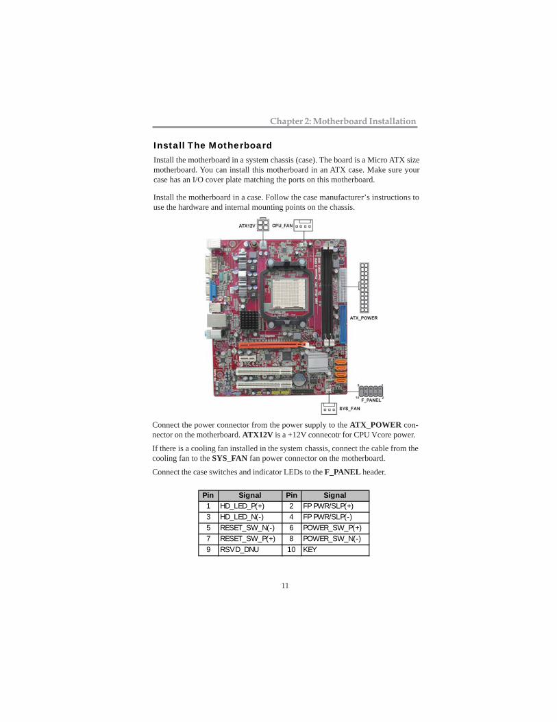
Install The MotherboardInstall the motherboard in a system chassis (case). The board is a Micro ATX sizemotherboard. You can install this motherboard in an ATX case. Make sure yourcase has an I/O cover plate matching the ports on this motherboard.
Connect the power connector from the power supply to the ATX_POWER con-nector on the motherboard. ATX12V is a +12V connecotr for CPU Vcore power.
If there is a cooling fan installed in the system chassis, connect the cable from thecooling fan to the SYS_FAN fan power connector on the motherboard.
Connect the case switches and indicator LEDs to the F_PANEL header.
Pin Signal Pin Signal
1 HD_LED_P(+) 2 FP PWR/SLP(+)
3 HD_LED_N(-) 4 FP PWR/SLP(-)
5 RESET_SW_N(-) 6 POWER_SW_P(+)
7 RESET_SW_P(+) 8 POWER_SW_N(-)
9 RSVD_DNU 10 KEY
Install the motherboard in a case. Follow the case manufacturer’s instructions touse the hardware and internal mounting points on the chassis.
12
Motherboard User’s Guide
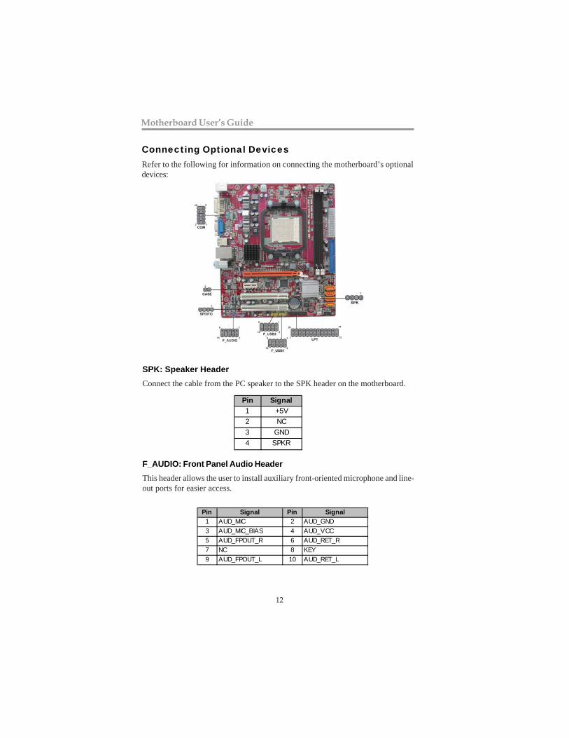
Connecting Optional DevicesRefer to the following for information on connecting the motherboard’s optionaldevices:
SPK: Speaker Header
Connect the cable from the PC speaker to the SPK header on the motherboard.
F_AUDIO: Front Panel Audio Header
This header allows the user to install auxiliary front-oriented microphone and line-out ports for easier access.
Pin Signal
1 +5V
2 NC
3 GND
4 SPKR
Pin Signal Pin Signal
1 AUD_MIC 2 AUD_GND
3 AUD_MIC_BIAS 4 AUD_VCC
5 AUD_FPOUT_R 6 AUD_RET_R
7 NC 8 KEY
9 AUD_FPOUT_L 10 AUD_RET_L

13
Chapter 2: Motherboard Installation
Here is a list of USB pin assignments.
1. Locate the F_USB1~2 headers on the motherboard.2. Plug the bracket cable onto the F_USB1~2 headers.3. Remove a slot cover from one of the expansion slots on the system chassis.
Install an extension bracket in the opening. Secure the extension bracket tothe chassis with a screw.
Pin Signal Pin Signal
1 VERG_FP_USBPWR0 2 VERG_FP_USBPWR0
3 USB_FP_P0(-) 4 USB_FP_P1(-)
5 USB_FP_P0(+) 6 USB_FP_P1(+)
7 GROUND 8 GROUND
9 KEY 10 GROUND
F_USB1~2: Front Panel USB Headers
The motherboard has USB ports installed on the rear edge I/O port array. Addition-ally, some computer cases have USB ports at the front of the case. If you have thiskind of case, use auxiliary USB headers F_USB1~2 to connect the front-mountedports to the motherboard.
SPDIFO: SPDIF out headerThis is an optional header that provides an S/PDIF (Sony/Philips Digital Interface)output to digital multimedia device through optical fiber or coaxial connector.
Pin Signal
1 SPDIF
2 +5VA
3 Key
4 GND

14
Motherboard User’s Guide
LPT: Onboard parallel port headerThis is a header that can ba used to connect to the printer, scanner or other devices.
1 STROBE 14 ALF
2 PD0
3 PD1
4 PD2
5 PD3
15 ERROR
16 INIT
17 SLCTIN
18 Ground
Pin Signal Name Pin Signal Name
6 PD4 19 Ground
7 PD5 20 Ground
8 PD6
9 PD7
10 ACK
11 BUSK
12 PE
13 SLCT
21 Ground
22 Ground
23 Ground
24 Ground
25 Ground
26 Key
CASE: Chassis intrusion detect headerThis detects if the chassis cover has been removed. This function needs a chassisequipped with instrusion detection switch and needs to be enabled in BIOS.
Pin 1-2 Function
Short Chassis cover is removed
Open Chassis cover is closed
COM: Onboard serial port headerConnect a serial port extension bracket to this header to add a second serial portto your system.
1 DCDB Data Carrier Detect
2 SINB Serial Input
3 SOUTB UART B Serial Output
4 DTRB UART B Data Terminal Ready
5 GND Ground
6 DSRB Data Set Ready
7 RTSB RART B Request to Send
8 CTSB Clear to Send
9 RI Ring Indicator10 Key No pin
Pin Signal Name Function

15
Chapter 2: Motherboard Installation
IDE Devices
IDE devices include hard disk drives, high-density diskette drives, and CD-ROMor DVD-ROM drives, among others.
The mainboard ships with an IDE cable that can support one or two IDE devices.If you connect two devices to a single cable, you must configure one of the drivesas Master and one of the drives as Slave. The documentation of the IDE device willtell you how to configure the device as a Master or Slave device. The Master deviceconnects to the end of the cable.
Install the device(s) and connect power from the system power supply. Use thecable provided to connect the device(s) to the Primary IDE channel connector IDE1on the motherboard.
If you want to install more IDE devices, you can purchase a second IDE cable andconnect one or two devices to the Secondary IDE channel connector IDE2 on themotherboard. If you have two devices on the cable, one must be Master and onemust be Slave.
Install Other DevicesInstall and connect any other devices in the system following the steps below.

16
Motherboard User’s Guide
Expansion SlotsThis motherboard has one PCI Express x16, one PCI Express x1 and two 32-bitPCI slots.
Serial ATA Devices
The Serial ATA (Advanced Technology Attachment) is the standard interface forthe IDE hard drives, which is designed to overcome the design limitations whileenabling the storage interface to scale with the growing media rate demands of PCplatforms. It provides you a faster transfer rate of 1.5 Gb/s. If you have installed aSerial ATA hard drive, you can connect the Serial ATA cables to the Serial ATA harddrive or the connector on the motherboard.
On the motherboard, locate the Serial ATA connectors SATA1-2, which supportnew Serial ATA devices for the highest data transfer rates, simpler disk drive cablingand easier PC assembly.
It eliminates limitations of the current Parallel ATA interface, but maintains registercompatibility and software compatibility with Parallel ATA.

17
Chapter 2: Motherboard Installation
Follow the steps below to install an PCI Express x16/ PCI Express x1/CNR/PCIexpansion card.
1. Locate the PCI Express x16, PCI Express x1, CNR or PCI slots on themainboard.
2. Remove the blanking plate of the slot from the system chassis.3. Install the edge connector of the expansion card into the slot. Ensure the
edge connector is correctly seated in the slot.4. Secure the metal bracket of the card to the system chassis with a screw.
PCI Express x16 Slot
You can install an external PCI Express graphics card that is fully compliant to thePCI Express Base Specification revsion 1.0a.
PCI Express x1 SlotThe two PCI Express x1 slots are fully compliant to the PCI Express Base Specifica-tion revision 1.0a as well.
PCI Slots
You can install the 32-bit PCI interface expansion cards in the slots.

18
Motherboard User’s Guide
Chapter 3 BIOS Setup Utility
IntroductionThe BIOS Setup Utility records settings and information of your computer, suchas date and time, the type of hardware installed, and various configurationsettings. Your computer applies the information to initialize all the componentswhen booting up and basic functions of coordination between system compo-nents.
If the Setup Utility configuration is incorrect, it may cause the system tomalfunction. It can even stop your computer booting properly. If it happens,you can use the clear CMOS jumper to clear the CMOS memory which hasstored the configuration information; or you can hold down the Page Up keywhile rebooting your computer. Holding down the Page Up key also clears thesetup information.
You can run the setup utility and manually change the configuration. You mightneed to do this to configure some hardware installed in or connected to themotherboard, such as the CPU, system memory, disk drives, etc.
Running the Setup UtilityEvery time you start your computer, a message appears on the screen before theoperating system loading that prompts you to “Hit <DEL>if you want to runSETUP” . Whenever you see this message, press the Delete key, and the Mainmenu page of the Setup Utility appears on your monitor.
You can use cursor arrow keys to highlight anyone of options on the main menupage. Press Enter to select the highlighted option. Press the Escape key to leavethe setup utility. Press +/-/ to modify the selected field’s values.
V02.67 (C) Copyright 1985-2009, American Megatrends, Inc.
CMOS Setup Utility – Copyright (C) 1985-2005, American Megatrends, Inc
Standard CMOS SetupAdvanced SetupAdvanced Chipset SetupIntegrated PeripheralsPower Management SetupPCI/PnP ConfigurationPC Health Status
Frequency/Voltage ControlLoad Default SettingsSupervisor PasswordUser PasswordSave & Exit SetupExit Without Saving
: Move Enter: Select +/-/: Value F10: Save Esc: Exit F1: General Help F9: Load Default Settings

19
Chapter 3: BIOS Setup Utility
CMOS Setup Utility – Copyright (C) 1985-2005, American Megatrends, Inc.Standard CMOS Setup
Date Wed 12/05/2010 Time 00: 11: 10
SATA1 Not DetectedSATA2 Not DetectedSATA3 Not DetectedSATA4 Not Detected
IDE Master Not Detected IDE Slave Not Detected
IDE BusMaster Enabled
Help Item
User [Enter], [TAB]or [SHIFT-TAB] toselect a field.
Use [+] or [-] toconfigure system Time.
Date & Time
These items set up system date and time.
SATA1~4/IDE Master/IDE Slave
Use these items to configure devices connected to the Primary/Secondary IDEchannels. To configure an IDE hard disk drive, choose Auto. If the Auto setting failsto find a hard disk drive, set it to User, and then fill in the hard disk characteristics(Size, Cyls, etc.) manually. If you have a CD-ROM drive, select the setting CDROM.If you have an ATAPI device with removable media (e.g. a ZIP drive or an LS-120),select Floptical.
IDE Bus Master
This item enables or disables the DMA under DOS mode. We recommend you toleave this item at the default value.
Some options on the main menu page lead to tables of items with installed valuesthat you can use cursor arrow keys to highlight one item, and press PgUp andPgDn keys to cycle through alternative values of that item. The other options onthe main menu page lead to dialog boxes requiring your answer OK or Cancel byselecting the [OK] or [Cancel] key.
If you have already changed the setup utility, press F10 to save those changesand exit the utility. Press F1 to display a screen describing all key functions.Press F9 to load optimtimal settings.
Standard CMOS Setup PageThis page displays a table of items defining basic information of your system.
: Move Enter: Select +/-/: Value F10: Save Esc: Exit F1: General Help F9: Optimized Defaults

20
Motherboard User’s Guide
Advanced Setup PageThis page sets up more advanced information about your system. Handle thispage with caution. Any changes can affect the operation of your computer.
HT Frequency (Auto)
This item enables users to manually set up the HyperTransport frequency, rangingfrom Auto, 1x, to 5x.
AMD C&Q (Enabled)
This item helps the system to lower the frequency when CPU idles. When thefrequency decreases, the temperature will drop automatically as well.
Quick Power on Self Test (Enabled)
Enable this item to shorten the power on testing (POST) and have your systemstart up faster. You might like to enable this item after you are confident that yoursystem hardware is operating smoothly.
BootUp Num-Lock Status (On)
This item defines if the keyboard Num Lock key is active when your system isstarted.
APIC Mode (Enabled)
This item allows you to enable or disable the APCI (Advanced ProgrammableInterrupt Controller) mode. APIC provides symmetric multi-processing (SMP)for systems, allowing support for up to 60 processors.
1st Boot Device/2nd Boot Device/3rd Boot Device
Use these items to determine the device order the computer uses to look for anoperating system to load at start-up time.
Try Other Boot Device
If you enable this item, the system will also search for other boot devices if itfails to find an operating system from the first two locations.
Boot to OS/2 > 64MB
Enable this item if you are booting the OS/2 operating system and you havemore than 64MB of system memory installed.
Aperture Size
This item defines the size of aperture if you use a graphic adapter.
Auto detect DIMM/PCI Clock
CMOS Setup Utility – Copyright (C) 1985-2005, American Megatrends, Inc.Advanced Setup
Help Item
Auto200 MHz400 MHz800 MHz1000 MHz
HT FrequencyAMD C&QQuick Power on Self TestBoot Up Numlock StatusAPIC Mode1st Boot Device2nd Boot Device3rd Boot DeviceBoot Other Device
AutoEnabledEnabledOnEnabledHard DriveCD/DVDRemovable Dev.Yes
: Move Enter: Select +/-/: Value F10: Save Esc: Exit F1: General Help F9: Load Default Settings
21
Chapter 3: BIOS Setup Utility
Boot Other Device (Yes)
When enabled, the system searches all other possible locations for an operatingsystem if it fails to find one in the devices specified under the First, Second andThird boot devices.
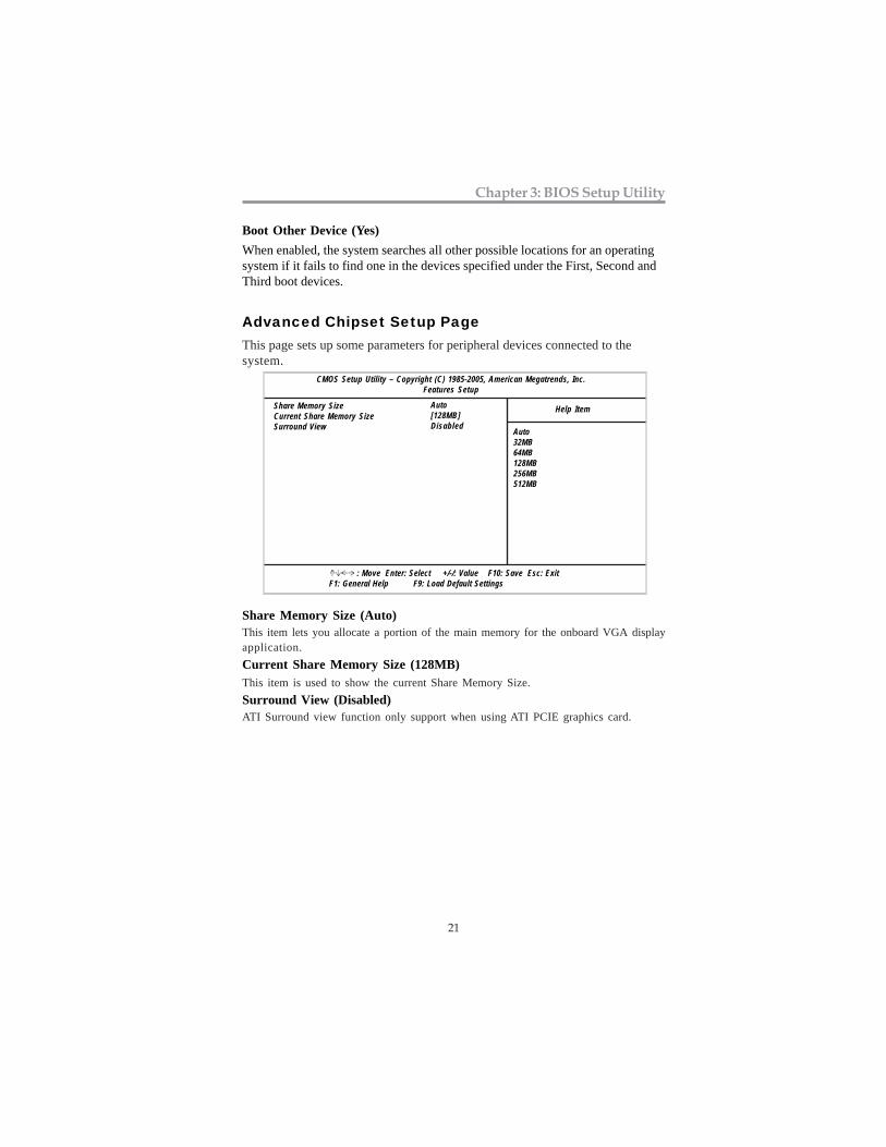
Advanced Chipset Setup PageThis page sets up some parameters for peripheral devices connected to thesystem.
CMOS Setup Utility – Copyright (C) 1985-2005, American Megatrends, Inc.Features Setup
Help Item
Auto32MB64MB128MB256MB512MB
Auto[128MB]Disabled
Share Memory SizeCurrent Share Memory SizeSurround View
Share Memory Size (Auto)This item lets you allocate a portion of the main memory for the onboard VGA displayapplication.
Current Share Memory Size (128MB)This item is used to show the current Share Memory Size.
Surround View (Disabled)ATI Surround view function only support when using ATI PCIE graphics card.
: Move Enter: Select +/-/: Value F10: Save Esc: Exit F1: General Help F9: Load Default Settings
22
Motherboard User’s Guide
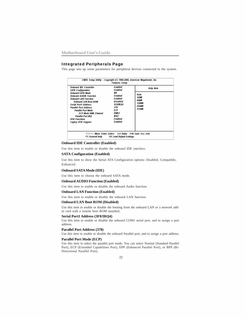
Integrated Peripherals PageThis page sets up some parameters for peripheral devices connected to the system.
CMOS Setup Utility – Copyright (C) 1985-2005, American Megatrends, Inc.Features Setup
Help Item
Auto32MB64MB128MB256MB512MB
EnabledEnabledIDEEnabledEnabledDisabled3F8/IRQ4378ECPDMA3IRQ7EnabledEnabled
Onboard IDE ControllerSATA ConfigurationOnboard SATA ModeOnboard AUDIO FunctionOnboard LAN Function Onboard LAN Boot ROMSerial Port1 AddressParallel Port Address Parallel Port Mode ECP Mode DMA Channel Parallel Port IRQUSB FunctionsLegacy USB Support
Onboard IDE Controller (Enabled)
Use this item to enable or disable the onboard IDE interface.
SATA Configuration (Enabled)
Use this item to show the Serial ATA Configuration options: Disabled, Compatible,
Enhanced.
Onboard SATA Mode (IDE)
Use this item to choose the onboard SATA mode.
: Move Enter: Select +/-/: Value F10: Save Esc: Exit F1: General Help F9: Load Default Settings
Onboard AUDIO Function (Enabled)
Use this item to enable or disable the onboard Audio function.
Onboard LAN Function (Enabled)
Use this item to enable or disable the onboard LAN function.
Onboard LAN Boot ROM (Disabled)
Use this item to enable or disable the booting from the onboard LAN or a network add-in card with a remote boot ROM installed.
Serial Port1 Address (3F8/IRQ4)Use this item to enable or disable the onboard COM1 serial port, and to assign a portaddress.
Parallel Port Address (378)Use this item to enable or disable the onboard Parallel port, and to assign a port address.
Parallel Port Mode (ECP)Use this item to select the parallel port mode. You can select Normal (Standard ParallelPort), ECP (Extended Capabilities Port), EPP (Enhanced Parallel Port), or BPP (Bi-Directional Parallel Port).

23
Chapter 3: BIOS Setup Utility
ECP Mode DMA Channel (DMA3)
Use this item to assign a DMA channel to the parallel port.
Parallel Port IRQ (IRQ7)Use this item to assign IRQ to the parallel port.
USB Functions (Enabled)Use this item to enable or disable the USB function.
Legacy USB Support (Enabled)Use this item to enable or disable support for legacy USB devices. Setting to Autoallows the system to detect the presence of USB device at startup. If detected, the USBcontroller legacy mode is enabled. If no USB device is detected, the legacy USB supportis disabled.
Power Management Setup PageThis page sets some parameters for system power management operation.
CMOS Setup Utility – Copyright (C) 1985-2005, American Megatrends, Inc.Power Management Setup
ACPI Suspend TypePWRON After PWR-FailResume By RINGResume By PCI/PCI-E/Lan PMEResume By PS2 KB (S3)Resume By PS2 MS (S3)Resumeon RTC Alarm
Help Item
Select the ACPIstate used forSystem Suspend.
S3Power OffDIsabledDisabledDisabledDisabledDisabled
: Move Enter: Select +/-/: Value F10: Save Esc: Exit F1: General Help F9: Load Default Settings
ACPI Suspend Type (S3)
Use this item to define how your system suspends. In the default, S3, the suspend modeis a suspend to RAM, i.e, the system shuts down with the exception of a refresh currentto the system memory.
PWRON After PWR-Fail (Power Off)
This item enables your computer to automatically restart or return to its operatingstatus.
Resume By RING
The system can be turned off with a software command. If you enable this item, thesystem can automatically resume if there is an incoming call on the Modem. You mustuse an ATX power supply in order to use this feature.
Resume By PCI/PCI-E/Lan PME
The system can be turned off with a software command. If you enable this item, thesystem can automatically resume if there is an incoming call on the PCI Modem or PCILAN card. You must use an ATX power supply in order to use this feature. Use this itemto do wake-up action if inserting the PCI card.

24
Motherboard User’s Guide
Allocate IRQ to PCI VGA
If this item is enabled, an IRQ will be assigned to the PCI VGA graphics system.You set this value to No to free up an IRQ.
Init Display First
Use this item to select which graphics controller to use as the primary boot devices.
PCI / Plug Setup PageThis page sets up some parameters for devices installed on the PCI bus and thoseutilizing the system plug and play capability.
CMOS Setup Utility – Copyright (C) 1985-2005, American Megatrends, Inc.PCI / Plug and Play Setup
Allocate IRQ to PCI VGA YesInit Display First PCI
Help Item
YES: Assigns IRQ toPCI VGA card if cardrequests IRQ.NO: Does not assignIRQ to PCI VGA cardeven if card requestsan IRQ.
: Move Enter: Select +/-/: Value F10: Save Esc: Exit F1: General Help F9: Load Default Settings
Resume By PS2 KB (S3)This item enables or disables you to allow keyboard activity to awaken the systemfrom power saving mode.
Resume By PS2 MS (S3)
The system can be turned off with a software command. If you enable this item,system can automatically resume by pressing any keys or power keys on thekeyboard, or typing in the password. You must use an ATX power supply inorder to use this feature.
Resume on RTC AlarmThe system can be turned off with a software command. If you enable this item, thesystem can automatically resume at a fixed time based on the system’s RTC (realtimeclock). Use the items below this one to set the date and time of the wake-up alarm. Youmust use an ATX power supply in order to use this feature.
Resume By USB (S3)This item allows you to enable/disable the USB device wakeup function from S3 mode.

25
Chapter 3: BIOS Setup Utility
PC Health Status PageOn motherboards support hardware monitoring, this item lets you monitor the param-eters for critical voltages, temperatures and fan speeds.
Smart Fan Function
CMOS Setup Utility – Copyright (C) 1985-2005, American Megatrends, Inc.BIOS Security Features
-=- System Hardware Monitor-=-Smart Fan Function Press EnterShutdown Temperature DisabledCPU Tcontrol : 51°C/123°FCPU Fan Speed : 2793 RPMCPU Vcore : 1.312VVDIMM : 1.520V
Case Open Warning DisabledChassis Opened No
Help Item
: Move Enter: Select +/-/: Value F10: Save Esc: Exit F1: General Help F9: Load Default Settings
CMOS Setup Utility – Copyright (C) 1985-2005, American Megatrends, Inc.Smart Fan Function
CPU SMART FAN Control EnabledSMART Fan Mode NormalHigh Limit Temperature. (° C ) 60High Limit Temperature. (° C ) 37High Limit PWM 200Low Limit PWM 56
Help Item
: Move Enter: Select +/-/: Value F10: Save Esc: Exit F1: General Help F9: Load Default Settings
This page sets up some parameters for devices installed on the PCI bus and thoseutilizing the system plug and play capability.
Options
DisabledEnabled
CPU SMART FAN Control
This item allows you to enable or disable the control of the CPU fan speed bychanging the fan voltage.
SMART Fan Mode
This item allows you to select the fan mode (Normal, Quiet, Silent, or Manual) for abetter operation environment. If you choose Normal mode, the fan speed will beauto adjusted depending on the CPU temperature. If you choose Quite mode, the fanspeed will be auto minimized for quiet environment. If you choose Silent mode, thefan speed will be auto restricted to make system more quietly. If you choose Manualmode, the fan speed will be adjust depending on users’ parameters.

26
Motherboard User’s Guide
CMOS Setup Utility - Copyright (C) 1985-2005, American Megatrends, Inc. Smart Fan Function
Help Item
F10: Save ESC: Exit+/-/: ValueEnter : Select: Move
CPU SMART FAN Control EnabledSMART Fan Mode QuietHigh Limit Temperature.(°C) 60Low Limit Temperature.(°C) 37High Limit PWM 200Low Limit PWM 56
Normal: auto adjustsdepending on the CPUtemperature.
Quiet: auto minimizesfan speed for quietenvironment operation.
Silent: auto restrictsfan speed to makesystem more quietly.
Manual: the fan adjustdepending on user’sparameter.
F9: Load Default SettingsF1:General Help
CMOS Setup Utility - Copyright (C) 1985-2005, American Megatrends, Inc. Smart Fan Function
Help Item
F10: Save ESC: Exit+/-/: ValueEnter : Select
F9: Load Default SettingsF1:General Help
: Move
CPU SMART FAN Control EnabledSMART Fan Mode SilentHigh Limit Temperature.(°C) 60Low Limit Temperature.(°C) 37High Limit PWM 200Low Limit PWM 56
Normal: auto adjustsdepending on the CPUtemperature.
Quiet: auto minimizesfan speed for quietenvironment operation.
Silent: auto restrictsfan speed to makesystem more quietly.
Manual: the fan adjustdepending on user’sparameter.

27
Chapter 3: BIOS Setup Utility
CMOS Setup Utility - Copyright (C) 1985-2005, American Megatrends, Inc. Smart Fan Function
Help Item
F10: Save ESC: Exit+/-/: ValueEnter : Select
F9: Load Default SettingsF1:General Help
: Move
CPU SMART FAN Control EnabledSMART Fan Mode ManualHigh Limit Temperature.(°C) 60Low Limit Temperature.(°C) 37High Limit PWM 200Low Limit PWM 56
Normal: auto adjustsdepending on the CPUtemperature.
Quiet: auto minimizesfan speed for quietenvironment operation.
Silent: auto restrictsfan speed to makesystem more quietly.
Manual: the fan adjustdepending on user’sparameter.
Shutdown TemperatureEnable you to set the maximum temperature the system can reach before powering
down.
System Component CharacteristicsThese items display the monitoring of the overall inboard hardware health events,such as System temperature & CPU Tcontrol, CPU & DIMM voltage, CPU & systemfan speed,...etc.
Case Open Warning (Disabled)This item enables or disables the warning if the case is opened up, and the item
below indicates the current status of the case.
• CPU Tcontrol • CPU FAN Speed • CPU Vcore
• VDIMM
Chassis Opened (No)
This item indicates whether the case has been opened.

28
Motherboard User’s Guide
Load Default SettingsThis option opens a dialog box to ask if you are sure to install optimized defaultsor not. You select [OK], and then <Enter>, the Setup Utility loads all defaultvalues; or select [Cancel], and then <Enter>, the Setup Utility does not load defaultvalues.
Auto Detect DIMM/PCI Clk
When this item is enabled, BIOS will disable the clock signal of free DIMM/PCI slots.
Memory Voltage
This item allows users to adjust the DDR3 memory voltage.
Spread Spectrum
If you enable spread spectrum, it can significantly reduce the EMI (Electro-MagneticInterference) generated by the system.
CPU Over-clocking FunctionThis item decides the CPU over-clocking function/frequency installed in your system.
Note: It is highly recommend that users enter this option to load optimal defaultvalues for accessing the best performance.
Frequency/Voltage Control PageThis page sets up some parameters for the hardware monitoring function of thismotherboard.
CMOS Setup Utility – Copyright (C) 1985-2005, American Megatrends, Inc.Frequency/Voltage Control
Auto Detect DIMM/PCI Clk EnabledMemory Voltage 1.6VSpread Spectrum EnabledCPU Over-clocking Function Disabled
Help Item
: Move Enter: Select +/-/: Value F10: Save Esc: Exit F1: General Help F9: Optimized Defaults
Options
DisabledEnabled
29
Chapter 3: BIOS Setup Utility
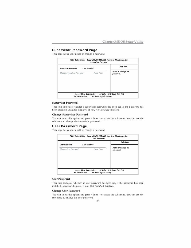
Supervisor Password PageThis page helps you install or change a password.
Supervisor Password : Not Installed
Change Supervisor Password Press Enter
Help Item
: Move Enter: Select +/-/: Value F10: Save Esc: Exit F1: General Help F9: Load Default Settings
CMOS Setup Utility – Copyright (C) 1985-2005, American Megatrends, Inc.Supervisor Password
Supervisor Password
This item indicates whether a supervisor password has been set. If the password hasbeen installed, Installed displays. If not, Not Installed displays.
Change Supervisor PasswordYou can select this option and press <Enter> to access the sub menu. You can use thesub menu to change the supervisor password.
User Password PageThis page helps you install or change a password.
User Password : Not Installed
Change User Password Press Enter
Help Item
: Move Enter: Select +/-/: Value F10: Save Esc: Exit F1: General Help F9: Load Default Settings
CMOS Setup Utility – Copyright (C) 1985-2005, American Megatrends, Inc.User Password
User Password
This item indicates whether an user password has been set. If the password has beeninstalled, Installed displays. If not, Not Installed displays.
Change User PasswordYou can select this option and press <Enter> to access the sub menu. You can use thesub menu to change the user password.
Install or Change thepassword.
Install or Change thepassword.

30
Motherboard User’s Guide
Save & Exit SetupHighlight this item and press <Enter> to save the changes that you have made in theSetup Utility configuration. When the Save Changes and Exit dialog box appears,select [OK] to save and exit, or [Cancel] to return to the main menu.
Exit Without SavingHighlight this item and press <Enter> to discard any changes that you have made inthe Setup Utility and exit the Setup Utility. When the Discard Changes and Exitdialog box appears, select [OK] to discard changes and exit, or [Cancel] to return tothe main menu.
Note: If you have made settings that you do not want to save, use the “DiscardChanges and Exit” item and select [OK] to discard any changes you havemade.
31
Chapter 4: Software & Applications
Chapter 4 Software & Applications
IntroductionThis chapter describes the contents of the support DVD-ROM/CD-ROM thatcomes with the motherboard package.
The support DVD-ROM/CD-ROM contains all useful software, necessary driv-ers and utility programs to properly run our products. More program informationis available in a README file, located in the same directory as the software.
To run the support disk, simply insert the disk into your DVD-ROM/CD-ROMdrive. An Auto Setup screen automatically pops out, and then you can go on theauto-installing or manual installation depending on your operating system.
If your operating system is Windows XP/7, it will automatically install all thedrivers and utilities for your motherboard.
Installing Support Software1 Insert the support DVD-ROM/CD-ROM disk in the DVD-ROM/CD-
ROM drive.2 When you insert the DVD-ROM/CD-ROM disk in the system DVD-
ROM/CD-ROM drive, the disk automatically displays an Auto Setupscreen.
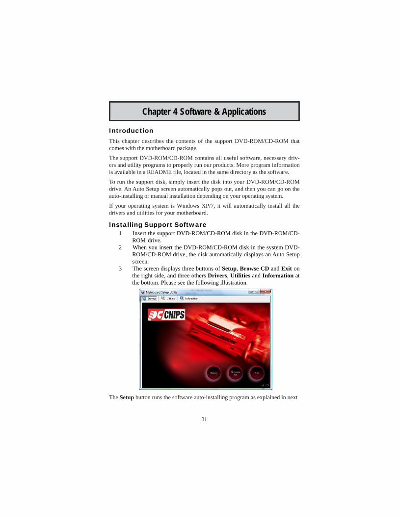
3 The screen displays three buttons of Setup, Browse CD and Exit onthe right side, and three others Drivers, Utilities and Information atthe bottom. Please see the following illustration.
The Setup button runs the software auto-installing program as explained in next

32
Motherboard User’s Guide
section.
The Browse CD button is a standard Windows command that you can check thecontents of the disc with the Windows file browsing interface.
The Exit button closes the Auto Setup window. To run the program again, reinsertthe DVD-ROM/CD-ROM disk in the drive; or click the DVD-ROM/CD-ROMdriver from the Windows Explorer, and click the Setup icon.
The Utilities button brings up a software menu. It shows the bundled softwarethat this mainboard supports.
The Information brings you to the Install Path where you can find out path namesof software driver.
Auto-Installing under Windows XP/7
If you are under Windows XP/7, please click the Setup button to run thesoftware auto-installing program while the Auto Setup screen pops out afterinserting the support DVD-ROM/CD-ROM:
1 The installation program loads and displays the following screen.Click the Next button.
2 Select the items that you want to setup by clicking on it (the defaultoptions are recommended). Click the Next button to proceed.

33
Chapter 4: Software & Applications
Bundled Software InstallationAll bundled software available on the DVD-ROM/CD-ROM is for users’ conve-nience. You can install bundled software as follows:
1 Click the Utilities button while the Auto Setup screen pops out afterinserting the support DVD-ROM/CD-ROM.
2 A software menu appears. Click the software you want to install.3 Follow onscreen instructions to install the software program step by
step until finished.
3 The support software will automatically install.
Once any of the installation procedures start, software is automatically installed insequence. You need to follow the onscreen instructions, confirm commands andallow the computer to restart as few times as needed to complete installing what-ever software you selected. When the process is finished, all the support softwarewill be installed and start working.
Windows Vista/7 will appear below UAC (User Account Control) messageafter the system restart. You must select “Allow” to install the next driver.
Continue this process to complete the drivers installation.
34
Motherboard User’s Guide
Setting Up a bootaSetting Up a bootaSetting Up a bootaSetting Up a bootaSetting Up a bootabbbbble RAID le RAID le RAID le RAID le RAID ArArArArArrrrrraaaaayyyyyThis section explains how to configure a bootable AMD RAID array.
Setting Up the BIOS
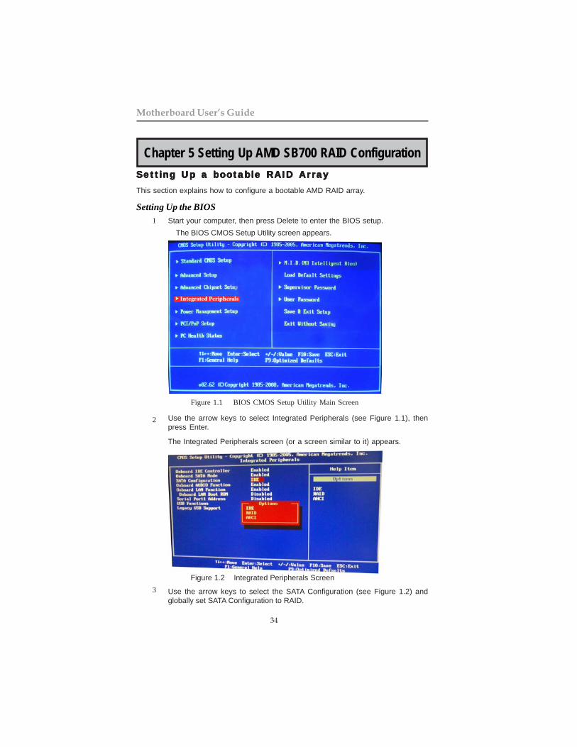
Use the arrow keys to select Integrated Peripherals (see Figure 1.1), thenpress Enter.
The Integrated Peripherals screen (or a screen similar to it) appears.
Figure 1.2 Integrated Peripherals Screen
Use the arrow keys to select the SATA Configuration (see Figure 1.2) andglobally set SATA Configuration to RAID.
Start your computer, then press Delete to enter the BIOS setup.
The BIOS CMOS Setup Utility screen appears.
Figure 1.1 BIOS CMOS Setup Utility Main Screen
1
2
3
Chapter 5 Setting Up AMD SB700 RAID Configuration
35
Chapter 5: Setting Up AMD SB700 RAID Configuration
Configuring the AMD RAID BIOS
The AMD RAID BIOS set up lets you choose the RAID type and which hard drives youwant to make part of the array.
Entering the RAID BIOS Setup:
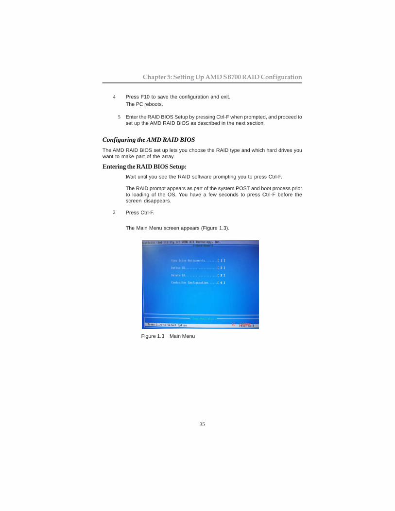
1Wait until you see the RAID software prompting you to press Ctrl-F.
The RAID prompt appears as part of the system POST and boot process priorto loading of the OS. You have a few seconds to press Ctrl-F before thescreen disappears.
Press Ctrl-F.2
The Main Menu screen appears (Figure 1.3).
Figure 1.3 Main Menu
5 Enter the RAID BIOS Setup by pressing Ctrl-F when prompted, and proceed toset up the AMD RAID BIOS as described in the next section.
The PC reboots.
Press F10 to save the configuration and exit.4

36
Motherboard User’s Guide
Select [2], then select LD 1 in the following page.3
The Define LD Menu screen appears (Figure 1.4).
Figure 1.4 Define LD Menu
Using the Define a New Array Screen
If necessary, press the tab key to move from field to field until the appropriate field ishighlighted.
• Selecting the RAID Mode
By default, this is set to Mirroring. To change to a different RAID mode, pressthe spacebar until the mode that you want appears in the RAID Mode box—RAID0/1/10/JBOD.
Note: Not all RAID levels are supported on all platforms.
Stripe block size is given in kilobytes, and affects how data is arranged on thedisk. It is recommended to leave this value at the default Optimal, which is64KB, but the values can be 64 KB and 128 KB. When choose RAID 1, theStripe block size is unchangable.
• Selecting the Stripe Block Size

37
Chapter 5: Setting Up AMD SB700 RAID Configuration
Figure 1.5 illustrates the Define a New Array screen after two disks havebeen assigned as RAID 0 array disks.
Figure 1.5 FastBuild Utility—Array Disks Assigned
Assigning the Disks
1. Select the Assignment to Y to designate a free disk to be used as a RAID arraydisk.
2. Press Ctrl-Y to save the configuration and exit.
The Define LD Menu screen appears (Figure 1.6).
Figure 1.6 Define LD Menu

38
Motherboard User’s Guide
Figure 1.7 Main Menu
Press ESC to exit.
4 Press Y to reboot.
3.
The Main Menu screen appears (Figure 1.7).
Figure 1.8
The following screen appears (Figure 1.8).

39
Chapter 5: Setting Up AMD SB700 RAID Configuration
1 Copy all files in "...\RAID\ATI\SB700\Floppy\Win3264" to a floppy disk.
After you complete the RAID BIOS setup, boot from the Windows CD.
Figure 1.10 Windows Setup—Specify Devices
Installing the RAID Drivers
Your system may come with a Windows install CD that already includes AMD RAIDdrivers. If so, then this section is not relevant.
If that is not the case (or you are trying to install a new version of Windows), then youwill need an AMD RAID driver F6 install floppy. Check to see if one came with yoursystem. If not, you can create one by downloading the appropriate driver package andfollowing the steps in this section.
Press F6 and wait a few moments for the Windows Setup screen toappear.
The Windows Setup program starts.
2
3
a Insert the floppy that has the RAID driver, press S, then press Enter.Specify the AMD drivers.4
Figure 1.9
40
Motherboard User’s Guide
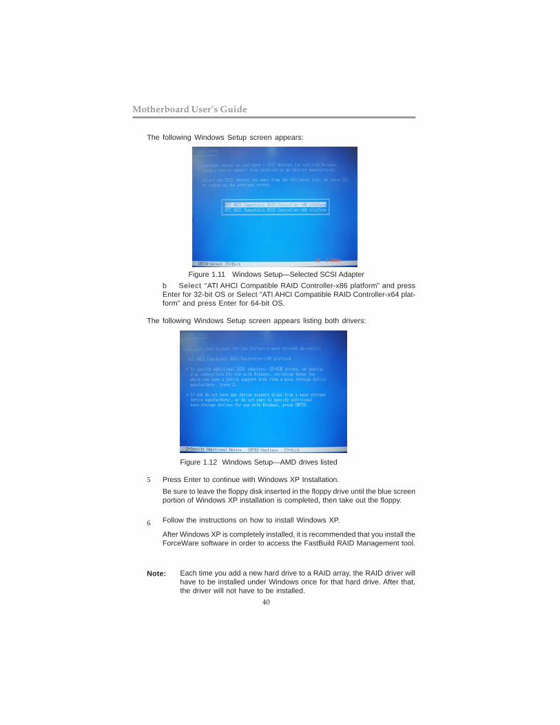
b Select “ATI AHCI Compatible RAID Controller-x86 platform” and pressEnter for 32-bit OS or Select “ATI AHCI Compatible RAID Controller-x64 plat-form” and press Enter for 64-bit OS.
The following Windows Setup screen appears listing both drivers:
Figure 1.12 Windows Setup—AMD drives listed
Press Enter to continue with Windows XP Installation.
Be sure to leave the floppy disk inserted in the floppy drive until the blue screenportion of Windows XP installation is completed, then take out the floppy.
Follow the instructions on how to install Windows XP.
After Windows XP is completely installed, it is recommended that you install theForceWare software in order to access the FastBuild RAID Management tool.
Note: Each time you add a new hard drive to a RAID array, the RAID driver willhave to be installed under Windows once for that hard drive. After that,the driver will not have to be installed.
5
6
Figure 1.11 Windows Setup—Selected SCSI Adapter
The following Windows Setup screen appears:

Chapter 6: Trouble Shooting Tips
41
StarStarStarStarStart up prt up prt up prt up prt up proboboboboblems during assemblems during assemblems during assemblems during assemblems during assemblllllyyyyy
After assembling the PC for the first time you may experience some start up problems.Before calling for technical support or returning for warranty, this chapter may help toaddress some of the common questions using some basic troubleshooting tips.
a) System does not power up and the fans are not running.
1.Disassemble the PC to remove the VGA adaptor card, DDR memory, LAN, USB andother peripherals including keyboard and mouse. Leave only the motherboard, CPU withCPU cooler and power supply connected. Turn on again to see if the CPU and powersupply fans are running.
2. Make sure to remove any unused screws or other metal objects such as screwdriversfrom the inside PC case. This is to prevent damage from short circuit.
3. Check the CPU FAN connector is connected to the motherboard.
4. For Intel platforms check the pins on the CPU socket for damage or bent. A bent pinmay cause failure to boot and sometimes permanent damage from short circuit.
5. Check the 12V power connector is connected to the motherboard.
6. Check that the 12V power & ATX connectors are fully inserted into the motherboardconnectors. Make sure the latches of the cable and connector are locked into place.
b) Power is on, fans are running but there is no display
1. Make sure the monitor is turned on and the monitor cable is properly connected to thePC.2. Check the VGA adapter card (if applicable) is inserted properly.3. Listen for beep sounds. If you are using internal PC speaker make sure it is connected. a. continuous 3 short beeps : memory not detected b. 1 long beep and 8 short beeps : VGA not detected
Chapter 6 Trouble Shooting Tips

Motherboard User’s Guide
42
c) The PC suddenly shuts down while booting up.
1. The CPU may experience overheating so it will shutdown to protect itself. Ensure theCPU fan is working properly.2. From the BIOS setting, try to disable the Smartfan function to let the fan run at defaultspeed. Doing a Load Optimised Default will also disable the Smartfan.
Your computer, like any electrical appliance, requires proper care and maintenance. Hereare some basic PC care tips to help prolong the life of the motherboard and keep itrunning as best as it can.
1. Keep your computer in a well ventilated area. Leave some space between the PC and the wall for sufficient airflow.
StarStarStarStarStart up prt up prt up prt up prt up proboboboboblems after prlems after prlems after prlems after prlems after prolong useolong useolong useolong useolong useAfter a prolong period of use your PC may experience start up problems again. This maybe caused by breakdown of devices connected to the motherboard such as HDD, CPU fan,etc. The following tips may help to revive the PC or identify the cause of failure.1. Clear the CMOS values using the CLR_CMOS jumper. Refer to CLR_CMOS jumper inChapter 2 for Checking Jumper Settings in this user manual. When completed, follow upwith a Load Optimised Default in the BIOS setup.
2. Check the CPU cooler fan for dust. Long term accumulation of dust will reduce itseffectiveness to cool the processor. Clean the cooler or replace a new one if necessary.
3. Check that the 12V power & ATX connectors are fully inserted into the motherboardconnectors. Make sure the latches of the cable and connector are locked into place.
4. Remove the hard drive, optical drive or DDR memory to determine which of thesecomponent may be at fault.
Maintenance and care tipsMaintenance and care tipsMaintenance and care tipsMaintenance and care tipsMaintenance and care tips
2. Keep your computer in a cool dry place. Avoid dusty areas, direct sunlight and areas of high moisture content.
3. Routinely clean the CPU cooler fan to remove dust and hair.
4. In places of hot and humid weather you should turn on your computer once every other week to circulate the air and prevent damage from humidity.
5. Add more memory to your computer if possible. This not only speeds up the system but also reduces the loading of your hard drive to prolong its life span.
6. If possible, ensure the power cord has an earth ground pin directly from the wall outlet. This will reduce voltage fluctuation that may damage sensitive devices.

Pow
er
Buon
is
pr
esse
d bu
t PC
fails
to st
art.
Yes
Chec
k if
Pow
er S
uppl
y U
nit (
PSU
) is
wor
king
No
No
Any
Beep
sou
nd?
N
o CL
R CM
OS
and
chec
k
if CP
U 1
2V p
ower
is c
onne
cted
art t
he P
C st
Re
Prob
lem
with
PSU
or b
oard
?
If bo
ard
prob
lem
-> c
onta
ct R
MA
AC p
ower
cor
d is
plu
ed
gg
and
PSU
switc
h is
turn
ed o
n?
Yes
oble
m
rBo
ard
p
-> c
onta
ct R
MA
No
- If 3
sho
rt b
eeps
:
DIM
M m
emor
y no
t pro
perly
inse
rted
or m
emor
y fa
ilure
- If 1
long
bee
p an
d 8
shor
t bee
ps:
VGA
not d
etec
ted
Yes
Yes
Hal
t at P
OST
scr
een?
Yes
R CM
OLC
S an
d re
star
t.
If fa
il, c
onta
ct R
MA
Yes
No
Perip
hera
l dev
ice
issu
e
-H
DD
pro
blem
.
-CM
OS
setu
p er
ror,
dne
e to
CLR
CMO
S.
Syst
em fa
il to
sta
rt o
r uns
tabl
e
aer
mod
ify B
IOS
seng
. M
CLR
CO
S an
d re
star
t
Turn
on
PSU
sw
itch
or c
onne
ct to
wal
l soc
ket
star
t. e
and
rNo
Chec
k if
mon
itor h
sadi
s pla
y
Chec
k if
mon
itor
has
dis
play
Basic
Tro
uble
shoo
ting
Flow
char
t


