Embed Size (px)
DESCRIPTION
rqwetq452514|5tujtky
Citation preview

I• IIIII.
MANUFACTURINGAUTOMATION
CIRO RODRIGUEZ
)
, !
.
METAL CUTTING MECHANICS,MACHINE TOOL VIBRATIONS,AND CNC DESIGN
YUSUF ALTINTASUniversity of British Columbia
..'~~ CAMBRIDGEUNIVERSITY PRESS
32 MECHANICS OF METAL CUTTING
The torque (T) and power (P) required from the spindle drive can be predictedby
acceptable
2,7MECHANICS OF MllLlNG PROCESSES33
2
8910
Qn-a.
~.-;'.,'",11''iGj 1)·t,·
ribbon
splral
1 long I shortchips
chipscomma commachips chips
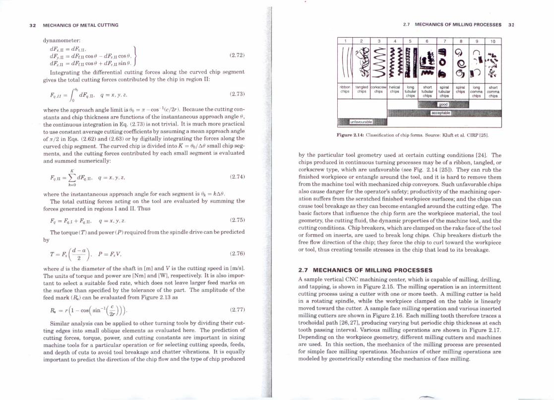
by the particular tool geometry used at certain cutting conditions [24]. Thechips produced in continuous turning processes may be of a ribbon, tangled, orcorkscrew type, which are unfavorable (see Fig. 2.14 [25]). They can rub thefinished workpiece or entangle around the tool, and it is hard to remove themfrom the machine tool with mechanized chip conveyors. Such un favorable chipsalso cause danger for the operator's safety; productivity of the machining oper-ation suffers from the scratched finished workpiece surfaces; and the chips cancause tool breakage as they can become entangled around the cutting edge. Thebasic factors that influence the chip form are the workpiece material, the toolgeometry, the cutting fluid, the dynamic properties ofthe machine tool, and thecutting conditions. Chip breakers, which are clamped on the rake face ofthe toolor formed on inserts, are used to break long chips. Chip breakers disturb thefree flow direction of the chip; they force the chip to curl toward the workpieceor tool, thus creating tensile stresses in the chip that lead to its breakage.
Figure 2.14: Classification of chip fonns. Source: Kluft et al. CIRP [25].
2.7 MECHANICS OF MILLlNG PROCESSESA sample vertical CNC machining center, which is capable of milling, drilling,and tapping, is shown in Figure 2.15. The milling operation is an intermittentcutting process using a cut ter with one or more teeth. A milling cutter is heldin a rotating spindle, while the workpiece cIamped on the table is linearlymoved toward the cutter. A sample face milling operation and various insertedmilling cutters are shown in Figure 2.16. Each milling tooth therefore traces atrochoidal path [26,27J, producing varying but periodic chip thickness at eachtooth passing intervaI. Various milling operations are shown in Figure 2.17.Depending on the workpiece geometry, different milling cutters and machinesare used. In this section, the mechanics of the milling process are presentedfor simple face milling operations. Mechanics of other milling operations aremodeled by geometrically extending the mechanics of face milling.
(2.74)
(2.75)
(2.77)
(2.73)
(2.76)
(2.72)
P = Fx V.
K
Fq,n = LdFq.n, q =x.y.Z.k=O
Fq = Fq,l + Fq.n, q = x. y. z.
Fq.ll = 1110dFq,n, q = x. y, z.
where the approach angle limit is 00 = :rr-cos-1(c/2r). Because the cutting con-stants and chip thickness are functions ofthe instantaneous approach angle O,
the continuous integration in Eq. (2.73) is not trivial. It is much more practicalto use constant average cutting coefficients by assuming a mean approach angleof :rr/2 in Eqs. (2.62) and (2.63) or by digitally integrating the forces along thecurved chip segmento The curved chip is divided into K = 00/ /:,,0 small chip seg-ments, and the cutting forces contributed by each small segment is evaluatedand summed numerically:
where the instantaneous approach angle for each segment is Ok = k/:"O.
The total cutting forces acting on the tool are evaluated by summing theforces generated in regions I and 11.Thus
Similar analysis can be applied to other turning tools by dividing their cut-ting edges into small oblique elements as evaluated here. The prediction ofcutting forces, torque, power, and cutting constants are important in sizingmachine tools for a particular operation or for selecting cutting speeds, feeds,and depth of cuts to avoid tool breakage aIld chatter vibrations. It is equallyimportant to predict the direction ofthe chip flowand the type of chip produced
(d-a)T = Fx -2- .where d is the diameter of the shaft in [mJ and V is the cutting speed in [mlsJ.The units oftorque and power are [NmJ and [WJ, respectively. It is also impor-tant to select a suitable feed rate, which does not leave larger feed marks onthe surface than specified by the tolerance of the parto The amplitude of thefeed mark (R.,) can be evaluated from Figure 2.13 as
dynamometer:
dFx,n = dFt,n. }dFy,1I = dFr,n cos o - dFr,n cosO.dFz,n = dFr,n cos o + dFr,n sin O,Integrating the differential cutting forces along the curved chip segment
gives the total cutting forces contributed by the chip in region 11:
34 MECHANICS OF METAL CUTTING 2.7 MECHANICS OF MILLlNG PROCESSES 35
Sall end mllllngRamp mlllingPlunge mllllng
Face mllllng
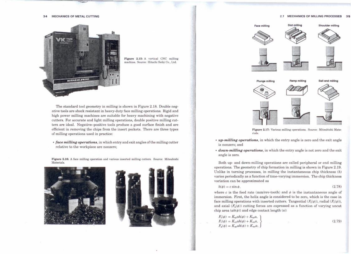
Figure 2.17: Various milling operations. Source: Mitsubishi Mate-rials.
Figure 2.15: A vertical CNC millingmachine. Source: Hitachi Seiki Co., Ltd.
The standard tool geometry in milling is shown in Figure 2.18. Double neg-ative tools are shock resistant in heavy-duty face milling operations. Rigid andhigh power milling machines are suitable for heavy machining with negativecutters. For accurate and light milling operations, double positive milling cut-ters are ideal. Negative-positive tools produce a good surface finish and areefficient in removing the chips from the insert pockets. There are three typesof milling operations used in practice:
• face milling operations, in which entry and exit angles ofthe milling cutterrelative to the workpiece are nonzero;
• up-milling operations, in which the entry angle is zero and the exit angleis nonzero; and
• down-milling operations, in which the entry angle is not zero and the exitangle is zero.
Both up- and down-milling operations are caBed peripheral or end millingoperations. The geometry ofchip formation in milling is shown in Figure 2.19.Unlike in turning processes, in milling the instantaneous chip thickness (h)varies periodically as a function oftime-varying immersion. The chip thicknessvariation can be approximated as
where e is the feed rate (mmlrev-tooth) and cf>is the instantaneous angle ofimmersion. First, the helix angle is considered to be zero, which is the case inface milling operations with inserted cutters. Tangential (Jit(cf>)), radial (Fr(cf>)),and axial (F.(cf>)) cutting forces are expressed as a function of varying uncutchip area (ah(cf>)) and edge contact length (a):
Ft(cf» = Kt.cah(cf» + Kt.ea, }
Fr(cf» = Kn;ah(cf» + Krea,F.(cf» = Kacah(cf» + K •• a,
(2.78)
(2.79)
h(cf» = e sin cf>.
Figure 2.16: A face milling operation and various inserted milling cutters. Source: MitsubishiMaterials.

36 MECHANICS OF METAL CUTTING 2.7 MECHANICS OF MILLlNG PROCESSES 37
b
(2.80)
(2.81)
x...F, (9)
chip load
Up milling
y Fy ( ~ )
Down milling
J:':' e sin </Jd</J cos </Jex- COS </JBtha = ----- = -c------.
</Jex- </JBt </Jex- </Jst
The instantaneous cutting torque (7;,)on the spindle is
chip formationin milling
Figure 2.19: Geometry of milling procesa.
zone as
D7;, = Ft . 2'
where D is the diame ter of the milling cutter. Horizontal (Le., feed), normal,and axial components ofthe cutting forces acting on the cutter are derived fromthe equilibrium diagram shown in Figure 2.19:
Bottomview(b)
Nega~ial rake angle
Effective diameter Slde view
Axial rake angle (negative)
-, . r-\ __ ~ .J~
Axlal relíe! angle
Axial rake angle (positiva)
Bottomview(a)
r~.'__dJií------~Axial relie! angle
Effective dlameter Side view
.' ~Radialrelie!I~~ -',angle_~ lJ ".
(c)
Figure 2.18: Standard face milling cuttar geometry.
Rake hPositive axial rake
~ I-
~Cutting-edge
angle
(2.82)where Ktc. Kre, and Kae are the cutting force coefficients contributed by theshearing action in tangential, radial, and rodal directions, respectively, andKte. Kre~ and Kae are the edge constants. If we assume zero nose radius andzero approach angle on the inserts, the axial components of the cutting forcesbecome zero (Fa = O). Otherwise their influence must be modeled as presentedin the section on turning (Section 2.6). The cutting coefficients are assumedto be constant for a tool-work material pair, and they can be evaluated eithermechanistically from milling tests or using the classical oblique cutting trans-formations given by Eqs. (2.62) and (2.63). They are sometimes expressed asa nonlinear function (Eq. 2.44) ofthe instantaneous or average chip thicknessha [28]. The average chip thickness per revolution is calculated from the swept
Fx(</J) = -Ftcos</J - Frsin</J'}Fy(</J) = +Ftsin</J - Frcos</J,
Fz(</J) = +Fa.It must be noted that the cutting forces are produced only when the cutting
tool is in the cutting zone, that is,
Fx(</J). Fy(</J). Fz(</J) > O when </Jst:::</J:::CPex.
where </JBtand </Jexare the cutter entry and exit angles, respectively. Anotherimportant point is that there may be more than one tooth cutting simultane-ously depending on the number of teeth on the cutter and the radial width of

38 MECHANICS OF METAL CUTTING
whenever t/>st .::: t/» .::: t/>ex. Each term in the summation block represents thecontribution of each tooth to the cutting forces. If the tooth j is out of theimmersion zone, it contri bute s zero to total forces. The instantaneous resultantcutting force on the cutter (or workpiece) is given as
where D is the diameter of the cutter. The cutting power (Pt) drawn from thespindle motor is
N
Pt = V· ¿Ft¡Ct/») --> t/>.t .:::t/» .::: t/>ex.)=1
cut. The tooth spacing angle t/>p (or cutter pitch angle) is given as27r
t/>p = N'where N is the number of teeth on the cutter. There will be more than onetooth cutting simuitaneously when the swept angle (t/>s = t/>ex - t/>st) is largerthan the cutter pitch angle (Le., t/>s > t/>ex - t/>st). When more than one toothcuts simultaneously, the contribution of each tooth to total feed and normalforces must be considered. It must also be noted that since each tooth will beaway from its neighboring tooth by the amount of pitch angle, the uncut chipthickness removed by each cutting edge will be different at an instantaneousposition ofthe cutter. We can formulate the total feed, normal, and axial forcesas
Spindle Rotation [deg]
E~O 50 100 150 200 250 300 350
2400
f~~O 50 100 150 200 250 300 350
Eu (e) D~D ,o, ~O 50 100 150 200 250 300 350
2.7 MECHANICS OF MILLlNG PROCESSES 39
Figure 2.20: Sirnulated resultant rnilling forees. Faee rnilling eutter: N = 4 teeth, a =2 rnrn. e = 0.1 rnm/tooth, K, = 1.800 MPa, Kr = 0.3. a) Halfirnrnersion up rnilling, b) halfirnrnersion down rnilling, e) eenter faee rnilling with 4>., = 75°. 4>•• , = 105°.
engineers are advised to use up-milling operations for heavy metal removalrates where the shock loading is reduced. For light tinish cuts, down-millingis preferred in order to obtain a smooth surface tinish. Center face milling hassevere interrupted, pulse loading of the machine tool, which is not advised forlight machines and positive tools. Pulse loading of the machine may resonatevarious structural vibration modes as well as cause transient vibrations duringeach entry and exit.
(2.84)
(2.83)
(2.85)
(2.86)
N
Fz = ¿Fz)(t/»).)=1
N
Fy = ¿Fy¡Ct/»),)=1
N
Fx = "Efx)(t/».)=1
F= 1r;+FJ+F¡.Instantaneous cutting torque on the spindle is
D NTe = "2 .¿Ft)(t/») --> t/>st .::: t/» .::: t/>ex.
)=1
where V = 7r Dn is the cutting speed and n is the spindle speed. For a givenset of cutting conditions, the engineer may be required to predict the maxi-mum cutting power, torque, and cutting forces required from the machine toolspindle"and feed drives. The cutting forces, torque, and power are uniformlyperiodic at tooth passing frequency. Periodic cutting forces dynamically loadand unload the machine tool structure, workpiece, and the cutter at each toothperiodo Typical resultant cutting forces for three types of milling operationsare shown in Figure 2.20. Half-immersion (Le., b = D/2) up- and down-millingforces have opposite trends. The chip load starts with zero and gradually in-creases to maximum at the exit in up-milling; hence forces have the same trend.However, the tooth experiences maximum chip load during entry followed by agradual decrease of the chip load and hence the cutting forces. Manufacturing
2.7.1 Mechanics of Helical End Milis
Periodic loading causes cyclic mechanical and thermal stress es on the tool,which leads to a shorter tool life. Helical end milis are used to dampen thesharp variations in the oscillatory components of the milling forces, and theyare used when the depth of cut is large but the width of cut is smal1. Theirprimary function is peripheral milling, where the walls of parts are the targettinish surface. A typical end milling cutter with helical flutes is shown inFigure 2.21. The helix on the cutter provides a gradually increasing chip loadalong the helical flutes of the end mili [29]. If the helix angle on the cutteris {J, a point on the axis of the cutting edge will be lagging behind the endpoint of the too1. The lag angle (1/F) at the axial depth of cut (z) is found as

40 MECHANICS OF METAL CUTTING 2.8 ANALYTICAL MODELlNG OF END MILlING FORCES 41
Rotation angle [degree)Figure 2.22: Simulated and measured cutting forces in en,milling of TiSAl4V alloy. Feed rate = 0.05 mm/tooth, an = (a) !lo = 9.05 mm, V = 30 m/min, Nf = 4 flutes, an = 12°, axi.depth of cut = 5.08 mm, io = 30°. b) Single flute ball end milwith radius !lo = 9.525 mm, nominal helix angle io = 30'axial depth ofcut = 1.27 mm, spindle speed N = 269 rev/mir
a)Half immersion Up millingwith a cylindrical end mili
~ 800[t;.600
~ 400~. /\ 11\ FY7~'\\
~ 20~j~\~~\ /~~". /F~~~c: -200 )( F''i! , '- x;:] ·400 ',_ ~~ __ "-_"';-o -600 - ~~
o 45 90 135 180 225 270 315 36CRotation angle [degree)
~ 300 b) Slot ball end millingt;. 1 Fz
(2.87)
andD1/1tan f3 = z.;
2z tan f3
1/1= -D-'
(Fig. 2.21)
When the bottom point of areference flute of the end millis at immersion angle ¡P, a cut-ting edge point that is axiallyz [mm] above will have an im-mersion angle of (¡P- 1/1). Obvi-ously, the chip thickness removedalong the flute's axis will also bedifferent at each point. A gen-eral pseudocode of a milling forcesimulation program is given inTable 2.2. The input variables setby the user are helix, entry, andexit angles, axial depth of cut, thenumber of teeth, feed rate, spin-die speed, cutter diameter, andcutting constants. The cutter is ro-tated with small incremental an-gles. At each incremental rotation,the cutting forces are integrated axially along the sliced differential elementsfrom the bottom of the flute toward the final axial depth of cut.Sample experimental and simulation results for helical cylindrical and he-
lical ball end milling of a titanium alloy are given in Figure 2.22 [18,30]. Thecutting coefficients are obtained by transfonning orthogonal cutting constantsoftitanium given in Table 2.1 to oblique end mill geometry (see Eq. 2.62). Theagreement between the experimental and simulation results are very satisfac-tory owing to careful evaluation of shear stress, shear angle, and friction coef-ficient in a series of orthogonal tests, as well as accurate modeling of geometryand oblique transfonnation of mechanics. More complex milling cutters andoperations can also be modeled by employing the same mechanics approach, bydesigning a generalized, parametric milling cutter geometry as presented byAltintas and Lee [30].
2.8 ANALYTICAL MODELlNG OF END MILLlNG FORCESThe discrete simulation ofcutting forces in end milling has been explained in theprevious section. The accuracy of the cutting force prediction strongly dependson the selected digital integration interval. When the axial depth of cut is large
dE",
y
.Q.rp2
1
, HI
IIL.. -I-...J
- - ... -1 , 1
11I
I "
I I I Ial
. I I I I,
, , 1 I, ,/': fJ '.•....••,,
", I!
,,
~~
z
Figure 2.21: Geometry of helical end milling.

TABLE2.2. Pseudocode lor MillingForce SimulatíonAlgorithm 2.8 ANALYTICAL MODELlNG OF END MILLlNG FORCES 43
; Inputs:Cutting conditionsTool geometryCutting constantsIntegration angleIntegration height
; Outputs:Cutting force historyCutting torque and power history
,;Variables
cf>p=~
K= i~L=;"
i=ltoKcJ¡(i) = cJ¡st + itJ.cJ¡
F..(i) = Fy(i) = Ft(i) = 0.0k=ltoN<Pl = cJ¡(i) + (k - 1)cf>p
th = cJ¡1
:a.c. n. 4>st. cJ¡ex:D.N.fJ:Kti,. Krc. Kte. Kre:tJ.cJ¡:tJ.a
:Fx(4)). Fy(4)). F(4)):Tc(4)). Pc(4))
;Cutter pitch angle;Number of angular integration steps;Number ofaxial integration steps;Angular integration loop;Immersion angle of flute's bottom edge;Initialize the force integration registers;Calculate the force contributions of all teeth;Immersion angle for tooth k;Memorize the present immersion
in helical end milling operations, the differential element height in the axialdirection must be very smalI to avoid numerical oscilIations on the cutting forcewave forms. When the cutting forces are used to predict the vibrations of theend milI or workpiece, the numerical oscilIations lead to faulty simulation ofvibrations. Also, an accurate prediction offorce distribution along the end miliand flexible thin webs is necessary to predict the dimensional form errors lefton the tinish surface. When kinematics and certain properties of the millingprocess are considered, it is possible to derive semianalyticaf expressions forend milIing forces [311. An end milI with a helix angle of /3, diameter of D,and N number of flutes is assumed (see Fig. 2.21). The axial depth of cut(a) is constant and the immersion is measured clockwise from the normal (y)axis. Assuming that the bottom end of one flute is designated as the referenceimmersion angle 4>,the bottom end points ofthe remaining flutes are at angles4>¡(0)= 4>+ Np; j = O. 1.2 ... (N - 1). At an axial depth of cut Z the lag angleis '" = k¡¡z, where k¡¡ = (2 tan /3)/D. The immersion angle for flute j at axialdepth of cut z therefore is
(2.88)
Tangential (dFt.j), radial (dFr.j), and axial (dFa,j) forces acting on a differen-tial flute element with height dz are expressed similar to Eg. (2.79):
j = ltoLa(j) = j .tJ.ath = cJ¡1 - 2~n¡¡a(j)if 4>st .:': th .:':4>ex
h = e sin thtJ.Ft = tJ.a(Ktch + Kte)tJ.Fr = tJ.a(Krch + Kre)tJ.Fx = -tJ.Ftcosth - tJ.FrsinthtJ.Fy = tJ.Ftsinth - tJ.Frcosth
;Integrate along the axial depth of cut;Axial position;Update the immersion angle due helix;if the edge is cutting;then;Chip thickness at this point;Differential tangential force;Differential radial force;Differential feed force';Differential normal force
dFt.j(4). z) = [Ktchj(4)¡(z)) + Kte1dz. }dFr,¡(4). z) = [Krch¡(4)j(z)) + Kre1dz.dFa.j(4). z) = [Kachj(4)j(z)) + Kae1dz,
where the chip thickness is
(2.89)
(2.90)
stopend
,; Plot Fx(i). Fy{i}. Fi• Tc(i) with varying immersion 4>(i)
FAí) = Fx(i) + tJ.FxFy(i) = Fy(i) + tJ.FyFt(i) = Ft(i) + tJ.Ftelsenext jnext k
,; Resulting cutting force values at immersion angle cJ¡(i)
(2.91)
The directions ofthe cutting forces are aligned with the cutter axis. The cut-ting constants can be evaluated from Eg. (2.62) by accepting the helix angle asthe obligue angle ofthe end milI (Le., i = /3). The elemental forces are resolvedinto feed (x), normal (y), and axial (z) directions using the transformation
dFx.¡(4)¡(z)) = -dFt.j cos4>¡(z) - dFr.j sin 4>j(z).dFy,j(4)¡(z)) = +dFt,j sin 4>j(z) - dFr.j cos t/Jj(z).dFz./4>¡(z)) = +dFa,j'
Substituting the differential forces (Eg. 2.89) and the chip thickness (Eg. 2.90)into Eg. (2.91) leads to
dFx,j(4)j(z)) = {~[ -Ktc sin 24>¡(z) - KrcCl - cos 24>¡(z))]
+ [-Kte cos 4>¡(z) - Kre sin 4>j(z)J }dz.
dFy.¡(4)j(z)) = {~[KtcCl - cos 24>¡(z» - Krc sin 2t/J¡(z)] > (2.92)
+ [Kte sin 4>¡(z) - Kre cos t/Jj(z)J }dz.dFz.¡(4)j(z)) = [Kacc sin 4>¡(z)+ Kae1dz.
;Sum the cutting forces;contributed by the all'active edges
;Resultant cutting forc~;Cutting torque
F(i) =¡FJ(i) + FJ(i)
Tc(i) = ~Ft(í)nexti

44 MECHANICS OF METAL CUTTING 2.8 ANALYTICAL MODELlNG OF END MILLlNG FORCES 45
The differential cutting forces are integrated analytically along the in-cut por-tion ofthe flute j in order to obtain the total cutting force produced by the flute:
Fq(t/>j(z)) = [;. dFq(t/>j(z))dz, q =~,y, z, (2.93)Z).l
where Zj,l(t/>/z)) and Zj,2(t/>j(Z)) are the lower and upper axial engagement limitsof the in-cut portion of the flute j. The integrations are carried out by notingt/>j(z) = t/>+ Jt/>p- k{Jz, dt/>j(z) = -k{Jdz. Thus
F."j(t/>/z)) = {4~(J[-Kre cos 2t/>j(z) + Krc[2t/>j(z) - sin 2t/>/z)]]
1 }~~~+ k[Ktesint/>/z)-Krecost/>j(z)] ,(J Z;I(4)J(Z))
Fy,j(t/>/z)) = {~: [Ktc(2t/>j(z) - sin 2t/>j(z)) +Krccos 2t/>j(z)]]
1 }Zj,'(4)/Z))+ k[Ktecost/>j(Z) + Kresint/>/z)] ,(J Zj,I(4)J(z))
F ( ()) 1 [K (K ()]';.(4>J(z»z,j t/>j Z = k acccost/>jz) - aet/>j Z z' (4)(z))"
{J J,I J
(2.95)
(2.96)
(2.97)
N-l
Fz(t/» = L Fzj.j=O
N-l
Fy(t/» =L Fyj;j=O
N-l
;'Fz(t/» = L Fzj;j=O
The resultant cutting force acting on the milling cutter is
The values for the integration limits Zj,l and Zj,2 are taken from the caseslisted above substituted into (2.94), and the resulting expressions can be furthersimplified for an efficient computation in computer programs. Note that to usethe expressions, flute j = O must be aligned at t/> = O in the beginning of thealgorithm. The remaining flutes must be indexed (j = 1, 2, ... ,N - 1) from thereference tooth at pitch angle (t/>p)intervals. The cutting forces contributed byall flutes are calculated and summed to obtain the total instantaneous forceson the cutter at immersion t/>:
2.8.1 Mechanistic Identification of Cutting Constants in MillingUsing orthogonal cutting parameters such as shear angle, shear stress, and
friction coefficient to determine oblique milling constants is desired for model-ing a variety of milling cutter geometries (see Eqs. 2.62 and 2.62). However,some cutting tools may have complex cutting edges, and the evaluation of cut-ting constants by creating a time-consuming orthogonal cutting data base maynot be possible. In such cases, a quick method of calibrating the milling tools,the mechanistic approach, is used [18]. A set of milling experiments are con-ducted at different feed rates but constant immersion and axial depth of cut.The average forces per tooth period are measured. To avoid the influence ofrun out on the measurements, the total force per spindle revolution is collectedand divided by the number of teeth on the cutter. The experimentally evalu-ated average cutting forces are equated to analytically derived average millingforce expressions, which leads to the identification of cutting constants. Sincethe total material removed per tooth period is constant with or without helixangle, the average cutting forces are independent of helix angle. Replacingdz = a, t/>j(z) = t/>, and k{J = O in Eqs. (2.92) and integrating them over one rev-olution and dividing by the pitch angle (t/>p= 27C / N) yields to average millingforces per tooth period,
Thus computationally inefficient and approximate digital integration meth-ods are eliminated by the dosed form expressions of the instantaneous cuttingforces. The dosed form expressions can be used for process planning, investigat-ing the interaction between tool-workpiece structure and the milling process,and predicting finish surface. The algorithm can be efficiently implemented lothe CAD/CAM systems for milling process simulation [32].
1 14>"Fq = - Fq(t/>)dt/>,t/>p 4> ••
since the flute cuts only within the immersion zone (Le., t/>Bt<
(2.94)
• If t/>.t< t/>j(z = O) < t/>exthen Zj,l = O;
Case o: If t/>.t< t/>j(z = a) < t/>exthenZj.2 = a.
Case 1: t/>j(z = a) < t/>Btthen Zj,2 =(1/ k{J)(t/> + jt/>p - t/>.t).
• If t/>j(z = O) > t/>exand t/>j(z = a) < t/>exthenZj,l = (1/ k{J)(t/> + Jt/>p- t/>ex);Case 2: If t/>j(z = a) > t/>.t then Zj,2 = a.Case 3: If t/>j(z = a) < t/>.t then Zj,2 =
(1/ k{J)(t/> + jt/>p - t/>.t).
Case 4: If t/>j(z = O) > t/>exand t/>/z = a) >t/>exthe flute is out of cut.
The axial integration limits Zj,l and Zj.2
are required for each flute to implement thecutting force model. When extruded axi-ally each [t/>.t,t/>ex]cutter arc segment de-fines an immersion section that can interactwith a helical tooth j in five distinct ways(Fig. 2.23). The lag angle at full axial depthof cut Z= a is o/a= k{Ja.The following computer algorithm is used
in determining the axial integration bound-aries:
Figure 2.23: Helical flute-part face integrationzones, and difTerential forces on the cutting too1at a particular rotation angle '" and depth z,

46 MECHANICS OF METAL CUTTING2.9 MECHANICS OF DRILLlNG 4
Integrating the instantaneous cutting forces leads to
The average forces at each feed rate are measured, and the cutting-edge com-ponents (Fqe• Fqe) are estimated by a linear regression ofthe data. Finally, thecutting force coefficients are evaluated from Eqs. (2.99) and (2.100) as follows:
(2.102)THRUST¡ = Fz.i = Aeh/f¡¡.
Figure 2.24: Twist dril! geometry
~a-_mm __ H.'•••• ~
1~~~~J·j1- ..•. I
2
.1
where /f¡¡ is the Brinell hardness of the work material and Aeh is the instan-taneous indentation are a of the chisel edge. Aeh is evaluated as the product ofchisellength (2w/ sin(lr - t/le» and the contact length of spread material withthe lip (c/(2 cosYt». Considering both sides of the chisel contact, we have an
2.9 MECHANICS OF DRILLlNGA sample twist drill, which is used in drilling holes, is shown in Figure 2.24. Atwist drill has a chisel edge at the bottom and two helical cutting lips with ataper angle (Kt)that meet with the flutes with a helix angle of f3o.The helicalflutes do not cut; they are used to evacuate the chips from the drilled hole. Thechisel has a width of2w and an edge angle of t/le. The cutting lips have an offsetfrom the drill center due to chisel. The lips expand the hole by removing thematerial with a constant chip thickness (h) as the drill is fed into the materialat a feed rate of C [mm/rev]. The thrust force that is used to push the drill intothe work material, and the torque applied to the drill and spindle drive, arerequired to evaluate the mechanics of the drilling operations. The mechanicsof drilling must be analyzed separately for the chisel and cutting lip regions.
Chisel Edge. The chisel edge does not cut but only spreads the material side-ways by an indentation mechanism. Instead of using the laws of cutting, themechanics of indentation must be used. If the process is simplified as in ahardness test, then the thrust force acting on the chis el edge can be simplifiedas
(2.99)
(2.98)
(2.101)
(2.100)
lr FyeKte = Na .
- lrFxe
Kre= -¡::¡;-.
4FyeKtc = Na'
-4FxeK te = ---¡;¡;;-.
Na Na)
Fx = --Kn;c - -Kre.4 lr
Na ·NaFy = +TKteC + --;-Kte._ Na NaFz = +-Ksec + -Kse·
lr 2
The average cutting forces can be expressed by a linear function offeed rate (c)and an offset contributed by the edge forces:
F y = { ~:C[Ktc(24)- sin 24»+ Kn;cos 24>J]
Na }4>ex- 2[KtecOS4> + Kresin4>J .lr 4>8t
T.'I Na K K 4>exL' z = 2[- seCcos 4>+ se4>JA, .lr 'l'8t
Full immersion (Le., slotting) milling experiments are most convenient; herethe entry and exit angles are 4>8t= O and 4>ex= lr respectively. When fullimmersion conditions are applied to Eqs. (2.98), the average forces per toothperiod are simplified as
K _ lrFze K _ 2Fzese - Na' se - Na .
The procedure is repeated for each cutter geometry; hence the milling forcecoefficients can not be predicted prior to testing ofnewly designed cutters usingmechanistic models. However, oblique cutting transformation using basic or-thogonal cutting parameters can predict the cutting constants before the cutteris manufactured.
F x = { Nac [Ktc cos 2t/J- Kn;[24>- sin 2t/J]]8lr
Na }4>ex+ -[-Ktesin<t> + Krecost/JJ .2lr <t>8t


