Embed Size (px)
DESCRIPTION
Airbus
Citation preview
B r i t i s h A i r w a y s E n g i n e e r i n g T r a i n i n g
Your Course NotesThese notes have been prepared by BritishAirways Engineering Training to provide asource of reference during your period oftraining.
The information presented is as correct aspossible at the time of printing and is notsubject to amendment action.
They will be useful to you during yourtraining, but I must emphasise that theappropriate Approved Technical Publicationsmust always be used when you are actuallyworking on the aircraft.
I trust your stay with us will be informativeand enjoyable.
JOHN QUINLISKTraining and Quality Delivery Manager
FLIGHT CONTROLS
GENERAL
Flight Controls Level 2 (2) . . . . . . . . . . . . . . . . . . . . . . . . . . . . . . . . . . 2
PITCH
Pitch Control Normal D/O (3) . . . . . . . . . . . . . . . . . . . . . . . . . . . . . . 24Pitch Control Abnormal D/O (3) . . . . . . . . . . . . . . . . . . . . . . . . . . . . 26Elevator Servo Control Operation (3) . . . . . . . . . . . . . . . . . . . . . . . . . 34THS Actuator Operation (3) . . . . . . . . . . . . . . . . . . . . . . . . . . . . . . . . 40
ROLL/YAW
Roll Control Normal D/O (3) . . . . . . . . . . . . . . . . . . . . . . . . . . . . . . . 42Roll Control Abnormal Operation (3) . . . . . . . . . . . . . . . . . . . . . . . . 44Yaw Control Normal D/O (3) . . . . . . . . . . . . . . . . . . . . . . . . . . . . . . . 58Yaw Control Abnormal D/O (3) . . . . . . . . . . . . . . . . . . . . . . . . . . . . . 62Aileron Servo Control Operation (3) . . . . . . . . . . . . . . . . . . . . . . . . . 64Spoiler Servo Control Operation (3) . . . . . . . . . . . . . . . . . . . . . . . . . 68Rudder Trim Actuator D/O (3) . . . . . . . . . . . . . . . . . . . . . . . . . . . . . . 76Rudder Servo Control Operation (3) . . . . . . . . . . . . . . . . . . . . . . . . . 78Rudder Limiter Operation (3) . . . . . . . . . . . . . . . . . . . . . . . . . . . . . . . 84Yaw Damper Servo Actuator Operation (3) . . . . . . . . . . . . . . . . . . . . 88Speed Brake & Ground Spoiler D/O (3) . . . . . . . . . . . . . . . . . . . . . . 96
EFCS GENERAL
Flight Control Warnings (3) . . . . . . . . . . . . . . . . . . . . . . . . . . . . . . . 104EFCS Control Interface (3) . . . . . . . . . . . . . . . . . . . . . . . . . . . . . . . 106EFCS Monitor Interface (3) . . . . . . . . . . . . . . . . . . . . . . . . . . . . . . . 132
SLATS AND FLAPS
Slats/Flaps Control D/O (3) . . . . . . . . . . . . . . . . . . . . . . . . . . . . . . . 134Slats/Flaps Abnormal Locking Operation (3) . . . . . . . . . . . . . . . . . 140Slats/Flaps Abnormal Half Speed Operation (3) . . . . . . . . . . . . . . . 148Slats Mechanical Drive D/O (3) . . . . . . . . . . . . . . . . . . . . . . . . . . . . 156
Flaps Mechanical Drive D/O (3) . . . . . . . . . . . . . . . . . . . . . . . . . . . 160Flaps Mechanical Drive D/O (3) (A321) . . . . . . . . . . . . . . . . . . . . . 164Flaps Drive Stations D/O (3) . . . . . . . . . . . . . . . . . . . . . . . . . . . . . . 168Flaps Drive Stations D/O (3) (A321) . . . . . . . . . . . . . . . . . . . . . . . . 174Flaps Attachment Failure DET Description (3) . . . . . . . . . . . . . . . . 182Slats/Flaps Warnings (3) . . . . . . . . . . . . . . . . . . . . . . . . . . . . . . . . . . 184SFCC Control Interfaces (3) . . . . . . . . . . . . . . . . . . . . . . . . . . . . . . . 186SFCC Monitor Interfaces (3) . . . . . . . . . . . . . . . . . . . . . . . . . . . . . . 188
MAINTENANCE COURSE - T1 (CFM56-5B/ME) 27 - FLIGHT CONTROLS
TABLE OF CONTENTS May 11, 2006Page 1
SINGLE AISLE TECHNICAL TRAINING MANUALU
3T06
191
- U
13T
1M0

FLIGHT CONTROLS LEVEL 2 (2)
SYSTEM OVERVIEW
The control is achieved through the following conventional surfaces.
PITCHPitch control is achieved by two elevators and the TrimmableHorizontal Stabilizer (THS). Elevators are used for short-term activity.The THS is used for long-term activity.
ROLLRoll control is achieved by one aileron and spoilers 2 to 5 on eachwing, numbered from wing root to wing tip.
YAWThe rudder fulfills yaw control. The rudder is used during cross windtake-off and landing, and in case of engine failure (thrust asymmetry).The yaw damper function controls the rudder for Dutch roll dampingand turn coordination.
SPEED BRAKESThe speed brake function is used in flight to increase the aircraft drag.Spoilers 2 to 4 are used. Roll orders and speed brake orders are addedwith priority given to the roll function.
GROUND SPOILERSThe ground spoiler function is used to destroy the lift during landingand in case of aborted take-off. All spoiler panels are used.
AILERON DROOPThe aileron droop function increases the lift on the part of the wingwhich is not equipped which flaps. The ailerons are deflecteddownwards when the flaps are extended.
MAINTENANCE COURSE - T1 (CFM56-5B/ME) 27 - FLIGHT CONTROLS
FLIGHT CONTROLS LEVEL 2 (2) May 10, 2006Page 2
SINGLE AISLE TECHNICAL TRAINING MANUALU
3T06
191
- U
13T
1M0
- U
M27
BA
0000
0000
1
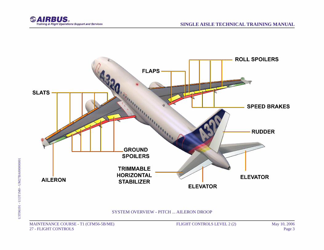
SYSTEM OVERVIEW - PITCH ... AILERON DROOP
MAINTENANCE COURSE - T1 (CFM56-5B/ME) 27 - FLIGHT CONTROLS
FLIGHT CONTROLS LEVEL 2 (2) May 10, 2006Page 3
SINGLE AISLE TECHNICAL TRAINING MANUALU
3T06
191
- U
13T
1M0
- U
M27
BA
0000
0000
1
FLIGHT CONTROLS LEVEL 2 (2)
SYSTEM OVERVIEW (continued)
HIGH LIFTSlats and flaps achieve the high lift function. There are two flaps,inboard and outboard, and five slats on each wing, numbered fromwing root to wing tip. The A321 is equipped with double slotted flaps.The slats and flaps are electrically controlled and hydraulicallyoperated. Two Slat Flap Control Computers (SFCCs) ensure controland monitoring. Each computer has one slat and one flap channel.The slat and flap systems are similar.A Power Control Unit (PCU) drives each system with two hydraulicmotors coupled to a differential gearbox. Torque shafts and gearboxestransmit the mechanical power to the actuators, which drive thesurfaces.Each motor is powered by a different hydraulic system and has itsown valve block and Pressure Off Brake (POB). Valve blocks controlthe direction of rotation and the speed of their related PCU outputshaft. The POB locks the transmission when the slat and flap surfaceshave reached the selected position or if hydraulic power fails.Wing Tip Brakes (WTBs) are provided in order to stop and lock thesystem when major failures are detected. They are hydraulicallyactivated and can only be reset on ground.Position Pick-Off Units (PPUs) send slat and flap position feedbackto the SFCCs and ECAM.Flap sensors installed between inboard and outboard flaps inhibitfurther flap operation when a flap attachment failure is detected. Thesignal is sent to the SFCCs via the Landing Gear Control and InterfaceUnits (LGCIU). To prevent an aircraft stall, slats cannot be fullyretracted at high angles of attack or low speeds (Alpha/speed lockfunction).
MAINTENANCE COURSE - T1 (CFM56-5B/ME) 27 - FLIGHT CONTROLS
FLIGHT CONTROLS LEVEL 2 (2) May 10, 2006Page 4
SINGLE AISLE TECHNICAL TRAINING MANUALU
3T06
191
- U
13T
1M0
- U
M27
BA
0000
0000
1

SYSTEM OVERVIEW - HIGH LIFT
MAINTENANCE COURSE - T1 (CFM56-5B/ME) 27 - FLIGHT CONTROLS
FLIGHT CONTROLS LEVEL 2 (2) May 10, 2006Page 5
SINGLE AISLE TECHNICAL TRAINING MANUALU
3T06
191
- U
13T
1M0
- U
M27
BA
0000
0000
1
FLIGHT CONTROLS LEVEL 2 (2)
SYSTEM OVERVIEW (continued)
COMPUTERSA computer arrangement permanently controls and monitors the flightcontrol surfaces, it also records and stores faults. This arrangementincludes:- 2 Elevator Aileron Computers (ELAC) for pitch and roll control,- 3 Spoiler Elevator Computers (SEC) for pitch and roll control,- 2 Flight Augmentation Computers (FAC) for yaw control,- 2 Flight Control Data Concentrators (FCDC) for indication andmaintenance tests,- 2 Flight Management Guidance Computer (FMGC) for autopilotcommands,- 2 Slat Flap Control Computers (SFCC) for slat and flap control.
MAINTENANCE COURSE - T1 (CFM56-5B/ME) 27 - FLIGHT CONTROLS
FLIGHT CONTROLS LEVEL 2 (2) May 10, 2006Page 6
SINGLE AISLE TECHNICAL TRAINING MANUALU
3T06
191
- U
13T
1M0
- U
M27
BA
0000
0000
1
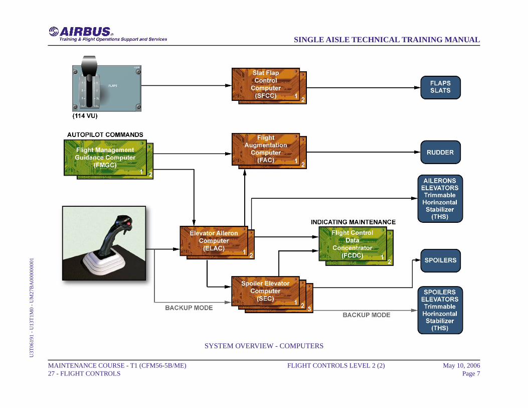
SYSTEM OVERVIEW - COMPUTERS
MAINTENANCE COURSE - T1 (CFM56-5B/ME) 27 - FLIGHT CONTROLS
FLIGHT CONTROLS LEVEL 2 (2) May 10, 2006Page 7
SINGLE AISLE TECHNICAL TRAINING MANUALU
3T06
191
- U
13T
1M0
- U
M27
BA
0000
0000
1
FLIGHT CONTROLS LEVEL 2 (2)
DAILY CHECK
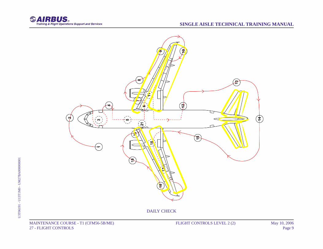
During the daily check, the external walk around will include the visualcheck for evidence of damage and fluid leakage of the:- Left and right wing leading edge slats,- Left and right wing trailing edge flaps and flap track fairings,- Left and right ailerons,- Left and right THS surfaces,- Left and right elevators,- Rudder.
NOTE: The visual check of the Flight Control Surfaces is made fromthe ground with Flaps/Slats in the retracted position.
MAINTENANCE COURSE - T1 (CFM56-5B/ME) 27 - FLIGHT CONTROLS
FLIGHT CONTROLS LEVEL 2 (2) May 10, 2006Page 8
SINGLE AISLE TECHNICAL TRAINING MANUALU
3T06
191
- U
13T
1M0
- U
M27
BA
0000
0000
1
DAILY CHECK
MAINTENANCE COURSE - T1 (CFM56-5B/ME) 27 - FLIGHT CONTROLS
FLIGHT CONTROLS LEVEL 2 (2) May 10, 2006Page 9
SINGLE AISLE TECHNICAL TRAINING MANUALU
3T06
191
- U
13T
1M0
- U
M27
BA
0000
0000
1
FLIGHT CONTROLS LEVEL 2 (2)
MEL/DEACTIVATION
AILERONSAs aileron servocontrol is a MMEL item, its deactivation is performedby disconnecting the related electrical connector. The detailedprocedure is given in the AMM.
SPOILERSThe spoiler servocontrol is a MMEL item. To deactivate the spoilerservocontrol, disconnect the electrical connector from the receptacleof the servocontrol.
NOTE: When you deactivate a spoiler servocontrol, you must alsodeactivate the symmetrical servocontrol on the other wing.
The detailed procedure is given in the AMM.
MAINTENANCE COURSE - T1 (CFM56-5B/ME) 27 - FLIGHT CONTROLS
FLIGHT CONTROLS LEVEL 2 (2) May 10, 2006Page 10
SINGLE AISLE TECHNICAL TRAINING MANUALU
3T06
191
- U
13T
1M0
- U
M27
BA
0000
0000
1

MEL/DEACTIVATION - AILERONS & SPOILERS
MAINTENANCE COURSE - T1 (CFM56-5B/ME) 27 - FLIGHT CONTROLS
FLIGHT CONTROLS LEVEL 2 (2) May 10, 2006Page 11
SINGLE AISLE TECHNICAL TRAINING MANUALU
3T06
191
- U
13T
1M0
- U
M27
BA
0000
0000
1
FLIGHT CONTROLS LEVEL 2 (2)
MEL/DEACTIVATION (continued)
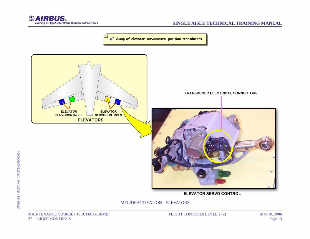
ELEVATORSThe elevator servocontrol position transducer (XDCR) is a MMELitem.If an ECAM warning "ELEVator SERVO FAULT "appears with aCentralized Fault Display System (CFDS) message "USE STandBYXDCR", the two plugs of the elevator servocontrol position XDCRsmust be swapped. Detailed procedures are given in the AMM.
MAINTENANCE COURSE - T1 (CFM56-5B/ME) 27 - FLIGHT CONTROLS
FLIGHT CONTROLS LEVEL 2 (2) May 10, 2006Page 12
SINGLE AISLE TECHNICAL TRAINING MANUALU
3T06
191
- U
13T
1M0
- U
M27
BA
0000
0000
1
MEL/DEACTIVATION - ELEVATORS
MAINTENANCE COURSE - T1 (CFM56-5B/ME) 27 - FLIGHT CONTROLS
FLIGHT CONTROLS LEVEL 2 (2) May 10, 2006Page 13
SINGLE AISLE TECHNICAL TRAINING MANUALU
3T06
191
- U
13T
1M0
- U
M27
BA
0000
0000
1
FLIGHT CONTROLS LEVEL 2 (2)
MEL/DEACTIVATION (continued)
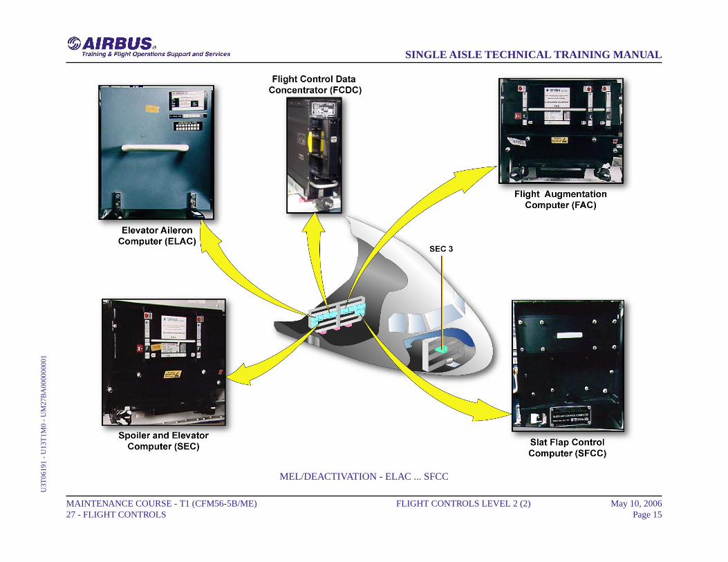
ELACThere are two ELACs (ELAC 1 and 2).Both ELACS are MEL items. Inoperative ELAC 2 is a NO GO item.Except for Extended Range (ER) operations, ELAC 1 or any ELAC1 function may be inoperative provided all the MMEL restrictions areapplied.Maintenance procedures related to ELAC 1 deactivation are detailedin the AMM.
SECThere are three SECs.Only one SEC out of three can be inoperative and deactivated providedall MMEL restrictions are applied.Maintenance procedures related to one SEC deactivation are detailedin the AMM.
FACThere are two FACs (FAC 1 and FAC 2) are installed on the A/C.An inoperative FAC 1 is a NO GO item.FAC 2 may be inoperative and deactivated provided all MMELrestrictions are applied.Maintenance procedures related to FAC 2 deactivation are detailedin the AMM.
FCDCThere are two FCDCs are installed on the A/C.An inoperative FCDC 1 is a NO GO item.FCDC 2 may be inoperative and deactivated following a flight crewprocedure.
SFCCSFCC1 and SFCC2 monitor and control the flaps.An inoperative SFCC 1 is a NO GO item.Only SFCC 2 flap and slat channel may be inoperative provided allrestrictions given in the MMEL are applied.
MAINTENANCE COURSE - T1 (CFM56-5B/ME) 27 - FLIGHT CONTROLS
FLIGHT CONTROLS LEVEL 2 (2) May 10, 2006Page 14
SINGLE AISLE TECHNICAL TRAINING MANUALU
3T06
191
- U
13T
1M0
- U
M27
BA
0000
0000
1
MEL/DEACTIVATION - ELAC ... SFCC
MAINTENANCE COURSE - T1 (CFM56-5B/ME) 27 - FLIGHT CONTROLS
FLIGHT CONTROLS LEVEL 2 (2) May 10, 2006Page 15
SINGLE AISLE TECHNICAL TRAINING MANUALU
3T06
191
- U
13T
1M0
- U
M27
BA
0000
0000
1
FLIGHT CONTROLS LEVEL 2 (2)
MEL/DEACTIVATION (continued)
WTBOn SLAT or FLAP WTBs, one or two solenoids associated with SFCC2 may be inoperative provided operation of SFCC 1 WTB is confirmedby a test before each flight.The related procedure for deactivation of the WTB solenoid is detailedin the AMM.
MAINTENANCE COURSE - T1 (CFM56-5B/ME) 27 - FLIGHT CONTROLS
FLIGHT CONTROLS LEVEL 2 (2) May 10, 2006Page 16
SINGLE AISLE TECHNICAL TRAINING MANUALU
3T06
191
- U
13T
1M0
- U
M27
BA
0000
0000
1
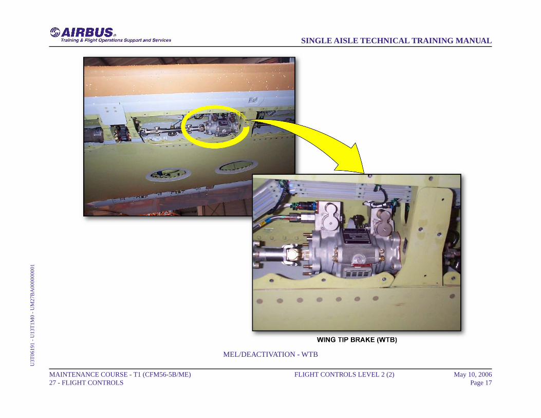
MEL/DEACTIVATION - WTB
MAINTENANCE COURSE - T1 (CFM56-5B/ME) 27 - FLIGHT CONTROLS
FLIGHT CONTROLS LEVEL 2 (2) May 10, 2006Page 17
SINGLE AISLE TECHNICAL TRAINING MANUALU
3T06
191
- U
13T
1M0
- U
M27
BA
0000
0000
1
FLIGHT CONTROLS LEVEL 2 (2)
MAINTENANCE TIPS - EXT/RET OF THE SPOILERS
EXTENSIONTo be unlocked, the servo control actuator must be depressurized.After the Flaps full extension the Slats/Flaps Locking Tool must beinstalled on the flap/slat control lever.Deactivate the spoilers electrical control by pulling the correspondingCircuits Breakers.The maintenance unlocking device tool can be engaged by using toa key equipped with a red flame.This tool cannot be removed when the servo control is in maintenancemode.
MAINTENANCE COURSE - T1 (CFM56-5B/ME) 27 - FLIGHT CONTROLS
FLIGHT CONTROLS LEVEL 2 (2) May 10, 2006Page 18
SINGLE AISLE TECHNICAL TRAINING MANUALU
3T06
191
- U
13T
1M0
- U
M27
BA
0000
0000
1

MAINTENANCE TIPS - EXT/RET OF THE SPOILERS - EXTENSION
MAINTENANCE COURSE - T1 (CFM56-5B/ME) 27 - FLIGHT CONTROLS
FLIGHT CONTROLS LEVEL 2 (2) May 10, 2006Page 19
SINGLE AISLE TECHNICAL TRAINING MANUALU
3T06
191
- U
13T
1M0
- U
M27
BA
0000
0000
1

FLIGHT CONTROLS LEVEL 2 (2)
MAINTENANCE TIPS - EXT/RET OF THE SPOILERS(continued)
SAFETY COLAR INSTALLATIONOnce the maintenance-unlocking device is engaged the spoiler surfacecan be raised manually for inspection purposes.After the spoiler is fully raised by hand, install the Safety Collar onthe servocontrol rod.
MAINTENANCE COURSE - T1 (CFM56-5B/ME) 27 - FLIGHT CONTROLS
FLIGHT CONTROLS LEVEL 2 (2) May 10, 2006Page 20
SINGLE AISLE TECHNICAL TRAINING MANUALU
3T06
191
- U
13T
1M0
- U
M27
BA
0000
0000
1
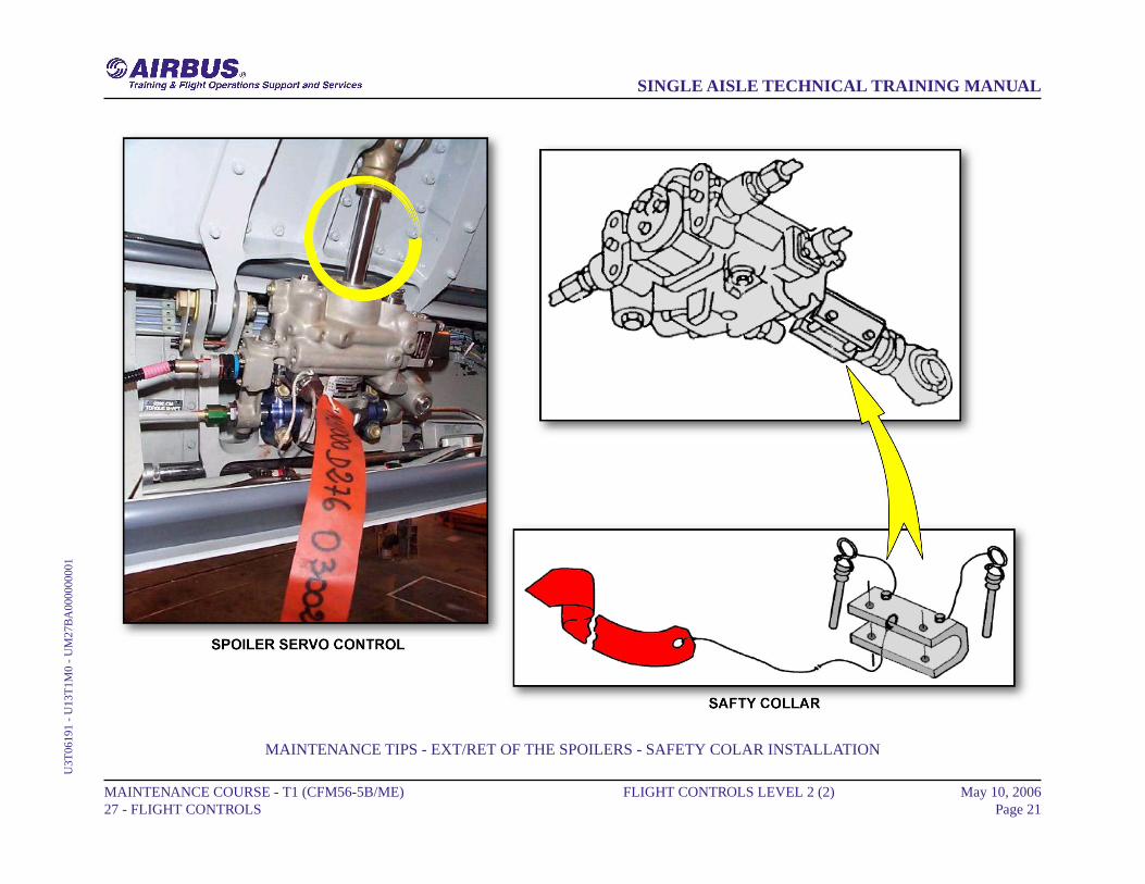
MAINTENANCE TIPS - EXT/RET OF THE SPOILERS - SAFETY COLAR INSTALLATION
MAINTENANCE COURSE - T1 (CFM56-5B/ME) 27 - FLIGHT CONTROLS
FLIGHT CONTROLS LEVEL 2 (2) May 10, 2006Page 21
SINGLE AISLE TECHNICAL TRAINING MANUALU
3T06
191
- U
13T
1M0
- U
M27
BA
0000
0000
1
FLIGHT CONTROLS LEVEL 2 (2)
MAINTENANCE TIPS - EXT/RET OF THE SPOILERS(continued)
RETRACTIONTo retract the spoiler, the Safety Collar must be removed from theservocontrol rod.When the maintenance unlocking device tool is turned and disengaged,the spoiler servocontrol is back to active mode.Reactivate the spoilers electrical control by reengaging thecorresponding Circuits Breakers.Do the operational test of the spoiler hydraulic actuation.Return the aircraft to the initial configuration (retract Flaps/Slats).
MAINTENANCE COURSE - T1 (CFM56-5B/ME) 27 - FLIGHT CONTROLS
FLIGHT CONTROLS LEVEL 2 (2) May 10, 2006Page 22
SINGLE AISLE TECHNICAL TRAINING MANUALU
3T06
191
- U
13T
1M0
- U
M27
BA
0000
0000
1

MAINTENANCE TIPS - EXT/RET OF THE SPOILERS - RETRACTION
MAINTENANCE COURSE - T1 (CFM56-5B/ME) 27 - FLIGHT CONTROLS
FLIGHT CONTROLS LEVEL 2 (2) May 10, 2006Page 23
SINGLE AISLE TECHNICAL TRAINING MANUALU
3T06
191
- U
13T
1M0
- U
M27
BA
0000
0000
1

PITCH CONTROL NORMAL D/O (3)
SIDE STICK
The side stick sends electrical orders to the ELevator Aileron Computers(ELACs) and Spoiler Elevator Computers (SECs).
ELAC
There are two ELACs. ELAC 2 normally controls the elevators andTrimmable Horizontal Stabilizer (THS) with ELAC 1 as a backup. Incase of ELAC 2 failure, ELAC 1 automatically takes over.
SEC
In case of dual ELACs failure, SEC 1 or 2 automatically takes over pitchcontrol.
FMGC
When the Autopilot (AP) is engaged, the Flight Management andGuidance Computer (FMGC) sends AP commands to the ELACs.
ELEVATORS
Each elevator is powered by two actuators, one in active mode, and theother in damping mode with automatic changeover in case of failure.Both actuators become active in case of large pitch demands. ELAC 2controls the green and yellow actuators and ELAC 1 controls the blueactuators.
THS
The THS is positioned by a screw actuator driven by two hydraulicmotors, which are controlled by one of the three electric motors. Oneelectrical trim motor is operative at a time, and the other two are instandby. Motor 1 is controlled by ELAC 2, motor 2 by ELAC 1 or SEC1, and motor 3 by SEC 2.
TRIM WHEELS
The mechanical trim, which has priority over the electrical trim, isoperated from the manual trim wheels.
MAINTENANCE COURSE - T1 (CFM56-5B/ME) 27 - FLIGHT CONTROLS
PITCH CONTROL NORMAL D/O (3) May 10, 2006Page 24
SINGLE AISLE TECHNICAL TRAINING MANUALU
3T06
191
- U
13T
1M0
- U
M27
D10
0000
0001

SIDE STICK ... TRIM WHEELS
MAINTENANCE COURSE - T1 (CFM56-5B/ME) 27 - FLIGHT CONTROLS
PITCH CONTROL NORMAL D/O (3) May 10, 2006Page 25
SINGLE AISLE TECHNICAL TRAINING MANUALU
3T06
191
- U
13T
1M0
- U
M27
D10
0000
0001
PITCH CONTROL ABNORMAL D/O (3)
ALTERNATE LAW
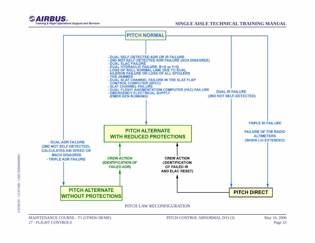
If the normal law of the ELevator Aileron Computer (ELAC) 2 fails, thecontrol goes to the ELAC 1. If the normal law of both ELACs fails, thealternate law takes over. The failures lead to an activation of the alternatelaw with reduced protections.
IN ELAC WITH PROTECTIONSAlternate law with reduced protections including load factor andstability augmentation, is active in ELAC 1 or 2 in case of either:- double self-detected Air Data Reference (ADR) or Inertial Reference(IR) failure,
- 2nd not self-detected ADR failure,- double hydraulic failure blue and green or yellow and green,- loss of roll normal law,- alternate law active in ELAC 1 with emergency electrical supply.
IN ELAC WITHOUT PROTECTIONSDepending on the failures, the pitch channel can switch to an alternatelaw without protections.Alternate law without protection including stability augmentation lostand load factor protection retained, is active in ELAC 1 or 2 in caseof either:
- 2nd not self-detected ADR failure,- triple ADR failure.
MAINTENANCE COURSE - T1 (CFM56-5B/ME) 27 - FLIGHT CONTROLS
PITCH CONTROL ABNORMAL D/O (3) May 10, 2006Page 26
SINGLE AISLE TECHNICAL TRAINING MANUALU
3T06
191
- U
13T
1M0
- U
M27
D20
0000
0001
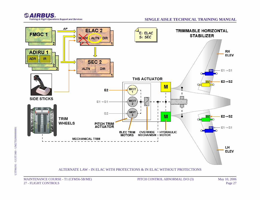
ALTERNATE LAW - IN ELAC WITH PROTECTIONS & IN ELAC WITHOUT PROTECTIONS
MAINTENANCE COURSE - T1 (CFM56-5B/ME) 27 - FLIGHT CONTROLS
PITCH CONTROL ABNORMAL D/O (3) May 10, 2006Page 27
SINGLE AISLE TECHNICAL TRAINING MANUALU
3T06
191
- U
13T
1M0
- U
M27
D20
0000
0001

PITCH CONTROL ABNORMAL D/O (3)
ALTERNATE LAW (continued)
IN SECAfter a double ELAC failure, alternate law with or without stabilityaugmentation, becomes active in the Spoiler Elevator Computer (SEC).
MAINTENANCE COURSE - T1 (CFM56-5B/ME) 27 - FLIGHT CONTROLS
PITCH CONTROL ABNORMAL D/O (3) May 10, 2006Page 28
SINGLE AISLE TECHNICAL TRAINING MANUALU
3T06
191
- U
13T
1M0
- U
M27
D20
0000
0001

ALTERNATE LAW - IN SEC
MAINTENANCE COURSE - T1 (CFM56-5B/ME) 27 - FLIGHT CONTROLS
PITCH CONTROL ABNORMAL D/O (3) May 10, 2006Page 29
SINGLE AISLE TECHNICAL TRAINING MANUALU
3T06
191
- U
13T
1M0
- U
M27
D20
0000
0001
PITCH CONTROL ABNORMAL D/O (3)
DIRECT LAW
If the alternate law is lost, the direct law computed in ELAC 1 or 2becomes active. The pitch direct law is active in case of either:- Dual IR failure,- triple IR failure,- failure of the RA.The auto trim is lost and the crew has to use the mechanical trim. In caseof loss of both ELACs when the alternate law is already lost, the directlaw computed in SEC 1 or 2 becomes active.
MECHANICAL BACK-UP
In case of total electrical failure or loss of all computers, pitch controlcan be achieved by the mechanical trim system. The four elevatoractuators are in centering mode.
MAINTENANCE COURSE - T1 (CFM56-5B/ME) 27 - FLIGHT CONTROLS
PITCH CONTROL ABNORMAL D/O (3) May 10, 2006Page 30
SINGLE AISLE TECHNICAL TRAINING MANUALU
3T06
191
- U
13T
1M0
- U
M27
D20
0000
0001

DIRECT LAW & MECHANICAL BACK-UP
MAINTENANCE COURSE - T1 (CFM56-5B/ME) 27 - FLIGHT CONTROLS
PITCH CONTROL ABNORMAL D/O (3) May 10, 2006Page 31
SINGLE AISLE TECHNICAL TRAINING MANUALU
3T06
191
- U
13T
1M0
- U
M27
D20
0000
0001
PITCH CONTROL ABNORMAL D/O (3)
PITCH LAW RECONFIGURATION
This diagram summarizes the pitch law reconfiguration.
MAINTENANCE COURSE - T1 (CFM56-5B/ME) 27 - FLIGHT CONTROLS
PITCH CONTROL ABNORMAL D/O (3) May 10, 2006Page 32
SINGLE AISLE TECHNICAL TRAINING MANUALU
3T06
191
- U
13T
1M0
- U
M27
D20
0000
0001
PITCH LAW RECONFIGURATION
MAINTENANCE COURSE - T1 (CFM56-5B/ME) 27 - FLIGHT CONTROLS
PITCH CONTROL ABNORMAL D/O (3) May 10, 2006Page 33
SINGLE AISLE TECHNICAL TRAINING MANUALU
3T06
191
- U
13T
1M0
- U
M27
D20
0000
0001
ELEVATOR SERVO CONTROL OPERATION (3)
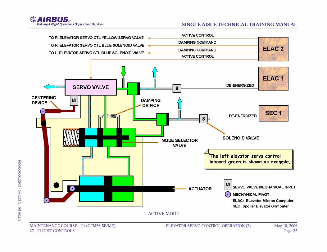
ACTIVE MODE
When the elevator servo control is in the active mode, it is pressurizedand both solenoid valves are de-energized. The servo valve is controlledby one computer at a time.
MAINTENANCE COURSE - T1 (CFM56-5B/ME) 27 - FLIGHT CONTROLS
ELEVATOR SERVO CONTROL OPERATION (3) May 10, 2006Page 34
SINGLE AISLE TECHNICAL TRAINING MANUALU
3T06
191
- U
13T
1M0
- U
M27
D30
0000
0001
ACTIVE MODE
MAINTENANCE COURSE - T1 (CFM56-5B/ME) 27 - FLIGHT CONTROLS
ELEVATOR SERVO CONTROL OPERATION (3) May 10, 2006Page 35
SINGLE AISLE TECHNICAL TRAINING MANUALU
3T06
191
- U
13T
1M0
- U
M27
D30
0000
0001
ELEVATOR SERVO CONTROL OPERATION (3)
DAMPING MODE
In case of a computer failure (e.g. ELAC2 failure), the related solenoidvalve is energized by the other computer and the elevator servo controlis in the damping mode as it is the actuator that is depressurized. Thiscauses the interconnection of the two actuator chambers through thedamping orifice.
MAINTENANCE COURSE - T1 (CFM56-5B/ME) 27 - FLIGHT CONTROLS
ELEVATOR SERVO CONTROL OPERATION (3) May 10, 2006Page 36
SINGLE AISLE TECHNICAL TRAINING MANUALU
3T06
191
- U
13T
1M0
- U
M27
D30
0000
0001

DAMPING MODE
MAINTENANCE COURSE - T1 (CFM56-5B/ME) 27 - FLIGHT CONTROLS
ELEVATOR SERVO CONTROL OPERATION (3) May 10, 2006Page 37
SINGLE AISLE TECHNICAL TRAINING MANUALU
3T06
191
- U
13T
1M0
- U
M27
D30
0000
0001
ELEVATOR SERVO CONTROL OPERATION (3)
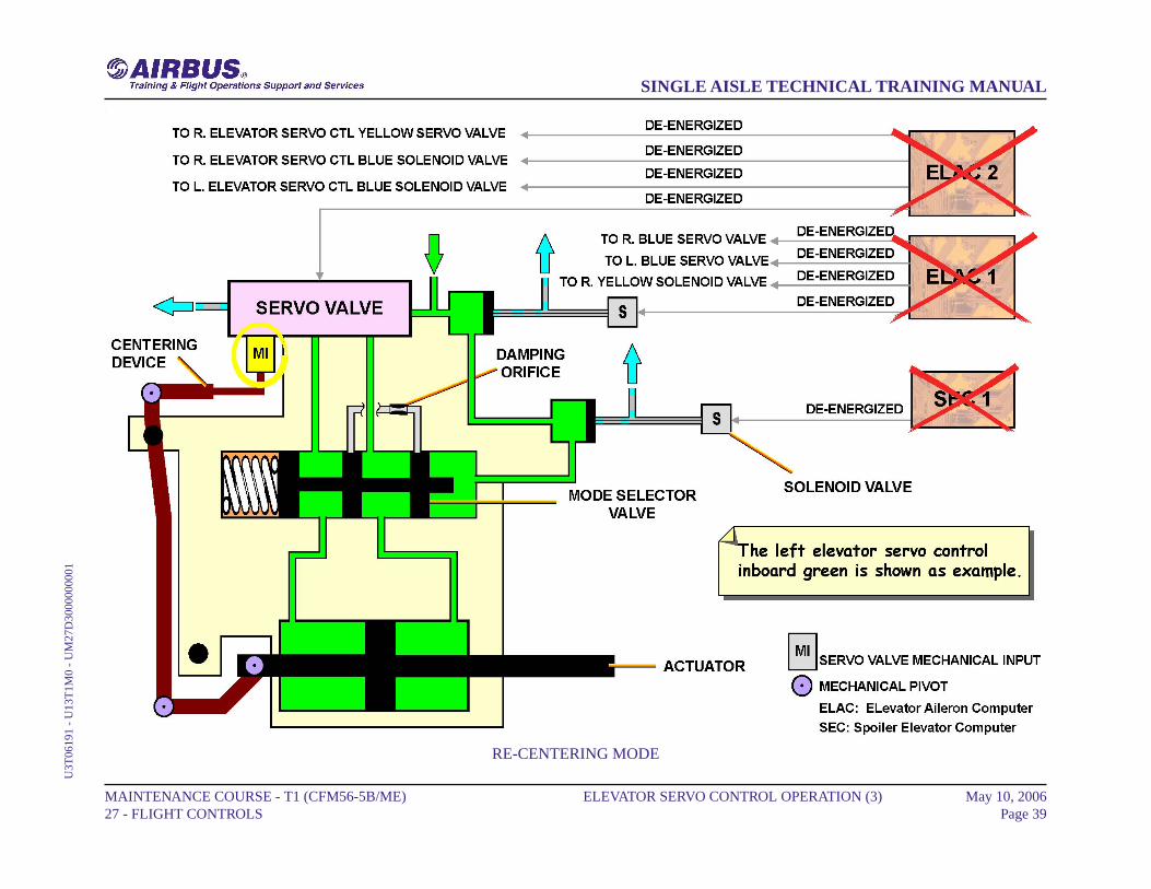
RE-CENTERING MODE
When the elevator servo control is in the re-centering mode, it ispressurized, the solenoid valves and servo valve are de-energized, theservo valve is centered to the neutral position by its mechanical input.Due to the centering device, the servo control actuator is maintainedhydraulically in its neutral position.
MAINTENANCE COURSE - T1 (CFM56-5B/ME) 27 - FLIGHT CONTROLS
ELEVATOR SERVO CONTROL OPERATION (3) May 10, 2006Page 38
SINGLE AISLE TECHNICAL TRAINING MANUALU
3T06
191
- U
13T
1M0
- U
M27
D30
0000
0001
RE-CENTERING MODE
MAINTENANCE COURSE - T1 (CFM56-5B/ME) 27 - FLIGHT CONTROLS
ELEVATOR SERVO CONTROL OPERATION (3) May 10, 2006Page 39
SINGLE AISLE TECHNICAL TRAINING MANUALU
3T06
191
- U
13T
1M0
- U
M27
D30
0000
0001
THS ACTUATOR OPERATION (3)
HYDRAULIC MOTORS
Both hydraulic motors drive the ball screw actuator through a powerdifferential gearbox. It moves up or down a ball nut on which theTrimmable Horizontal Stabilizer (THS) surface is mounted.
VALVE BLOCKS
One valve block is given for each hydraulic motor.
PRESSURE OF BRAKES
The Pressure-Off Brakes (POBs) are applied in case of hydraulic pressureloss.
ELECTRICAL MOTORS
Three electrical motors are installed; only one at a time can move theinput lever of the hydraulic valve blocks. Each one is driven by theelectrical flight through its corresponding computer.Electrical motors are controlled by:- ELevator Aileron Computer (ELAC) 2 for Motor 1,- ELAC 1 or Spoiler Elevator Computer (SEC) 1 for Motor 2,- SEC 2 for Motor 3.
POSITION TRANSDUCERS
The THS actuator has two inductive position transducer packages. Theyare the command position transducer and the monitor position transducer.Position transducers are installed to feed back, the actual position of theoverride mechanism output and the ball screw position to the ElectricalFlight Control System (EFCS) computer.
MANUAL MODE
The THS actuator can be operated manually from the THS trim handwheels on the center pedestal in the cockpit. They have priority over theelectric trim thanks to the override mechanism.
ELECTRIC MODE
Normally the THS actuator is operated by one electrical trim motorthrough an EFCS computer. Feedback is given to the THS trim handwheels in the cockpit.
JAMMING MODE
If one control valve or its driving mechanism is jammed the hydraulicsupply of both hydraulic motors is cut by the Shut-Off Valve (SOV)control device in each valve block, the comparator piston operates bothSOVs. The SOV can not detect a jamming. Both POBs are applied andthe THS is immobilized and locked.
MAINTENANCE COURSE - T1 (CFM56-5B/ME) 27 - FLIGHT CONTROLS
THS ACTUATOR OPERATION (3) May 10, 2006Page 40
SINGLE AISLE TECHNICAL TRAINING MANUALU
3T06
191
- U
13T
1M0
- U
M27
D40
0000
0001

HYDRAULIC MOTORS ... JAMMING MODE
MAINTENANCE COURSE - T1 (CFM56-5B/ME) 27 - FLIGHT CONTROLS
THS ACTUATOR OPERATION (3) May 10, 2006Page 41
SINGLE AISLE TECHNICAL TRAINING MANUALU
3T06
191
- U
13T
1M0
- U
M27
D40
0000
0001

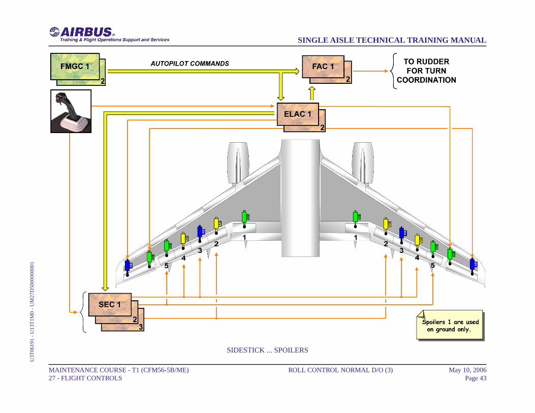
ROLL CONTROL NORMAL D/O (3)
SIDESTICK
The sidestick sends electrical orders to the ELevator Aileron Computers(ELACs) and Spoiler Elevator Computers (SECs).
ELAC
There are two ELACs: ELAC 1 normally controls the ailerons, withELAC 2 as back-up. In case of failure of ELAC 1, ELAC 2 willautomatically take control.
SEC
Using orders coming from the ELACs, each SEC sends orders to one ortwo pairs of spoilers, without back-up.
FAC
Flight Augmentation Computer (FAC) 1, with FAC 2 as back-up,transmits turn coordination orders for the rudder.
FMGC
When the autopilot is engaged, the Flight Management and GuidanceComputer (FMGC) sends roll commands to the ELACs and the FACs,and to the SECs through the ELACs via ARINC 429 data buses.
AILERONS
There are two electrically-controlled hydraulic actuators per aileron, onein active mode and the other in damping mode. The left blue and rightgreen actuators are controlled by ELAC 1 and the other two actuators byELAC 2. All aileron actuators revert to damping mode in case of a doubleELAC failure or green and blue hydraulic low pressure.
SPOILERS
Each spoiler is powered by one hydraulic actuator. Surfaces areautomatically retracted if a fault is detected by the monitoring system orif there is no electrical supply.In case of loss of hydraulic power supply:- if retracted, the surface remains retracted,- if not retracted, the surface will maintain existing deflection to the zerohinge moment position or less if pushed down by aerodynamics.
NOTE: Spoilers 1 are not used for roll control.
MAINTENANCE COURSE - T1 (CFM56-5B/ME) 27 - FLIGHT CONTROLS
ROLL CONTROL NORMAL D/O (3) May 10, 2006Page 42
SINGLE AISLE TECHNICAL TRAINING MANUALU
3T06
191
- U
13T
1M0
- U
M27
D50
0000
0001
SIDESTICK ... SPOILERS
MAINTENANCE COURSE - T1 (CFM56-5B/ME) 27 - FLIGHT CONTROLS
ROLL CONTROL NORMAL D/O (3) May 10, 2006Page 43
SINGLE AISLE TECHNICAL TRAINING MANUALU
3T06
191
- U
13T
1M0
- U
M27
D50
0000
0001
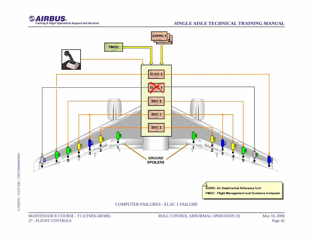
ROLL CONTROL ABNORMAL OPERATION (3)
COMPUTER FAILURES
A computer failure can engage a lateral abnormal configuration.
ELAC 1 FAILUREThe loss of ELevator Aileron Computer (ELAC) 1 leads to selectELAC 2 active. ELAC 2 computes the lateral orders in normal lawand transmits them to the Spoiler Elevator Computer (SEC) for theroll spoiler.
MAINTENANCE COURSE - T1 (CFM56-5B/ME) 27 - FLIGHT CONTROLS
ROLL CONTROL ABNORMAL OPERATION (3) May 10, 2006Page 44
SINGLE AISLE TECHNICAL TRAINING MANUALU
3T06
191
- U
13T
1M0
- U
M27
D60
0000
0001
COMPUTER FAILURES - ELAC 1 FAILURE
MAINTENANCE COURSE - T1 (CFM56-5B/ME) 27 - FLIGHT CONTROLS
ROLL CONTROL ABNORMAL OPERATION (3) May 10, 2006Page 45
SINGLE AISLE TECHNICAL TRAINING MANUALU
3T06
191
- U
13T
1M0
- U
M27
D60
0000
0001
ROLL CONTROL ABNORMAL OPERATION (3)
COMPUTER FAILURES (continued)
ELAC 1+2 FAILUREIn case of loss of both ELACs only spoilers are available. The SECscontrol the roll in direct law and the yaw damping function normallaw is lost.
MAINTENANCE COURSE - T1 (CFM56-5B/ME) 27 - FLIGHT CONTROLS
ROLL CONTROL ABNORMAL OPERATION (3) May 10, 2006Page 46
SINGLE AISLE TECHNICAL TRAINING MANUALU
3T06
191
- U
13T
1M0
- U
M27
D60
0000
0001

COMPUTER FAILURES - ELAC 1+2 FAILURE
MAINTENANCE COURSE - T1 (CFM56-5B/ME) 27 - FLIGHT CONTROLS
ROLL CONTROL ABNORMAL OPERATION (3) May 10, 2006Page 47
SINGLE AISLE TECHNICAL TRAINING MANUALU
3T06
191
- U
13T
1M0
- U
M27
D60
0000
0001

ROLL CONTROL ABNORMAL OPERATION (3)
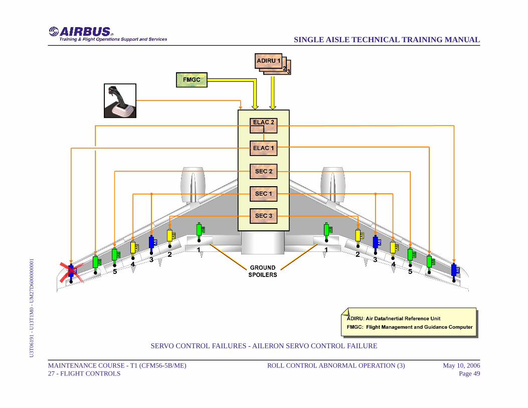
SERVO CONTROL FAILURES
AILERON SERVO CONTROL FAILUREIn case of failure of one aileron servo control, the second one takesover and is controlled by the other ELAC. In this example, ELAC 1still computes the orders and ELAC 2 is in slave mode.
MAINTENANCE COURSE - T1 (CFM56-5B/ME) 27 - FLIGHT CONTROLS
ROLL CONTROL ABNORMAL OPERATION (3) May 10, 2006Page 48
SINGLE AISLE TECHNICAL TRAINING MANUALU
3T06
191
- U
13T
1M0
- U
M27
D60
0000
0001
SERVO CONTROL FAILURES - AILERON SERVO CONTROL FAILURE
MAINTENANCE COURSE - T1 (CFM56-5B/ME) 27 - FLIGHT CONTROLS
ROLL CONTROL ABNORMAL OPERATION (3) May 10, 2006Page 49
SINGLE AISLE TECHNICAL TRAINING MANUALU
3T06
191
- U
13T
1M0
- U
M27
D60
0000
0001
ROLL CONTROL ABNORMAL OPERATION (3)
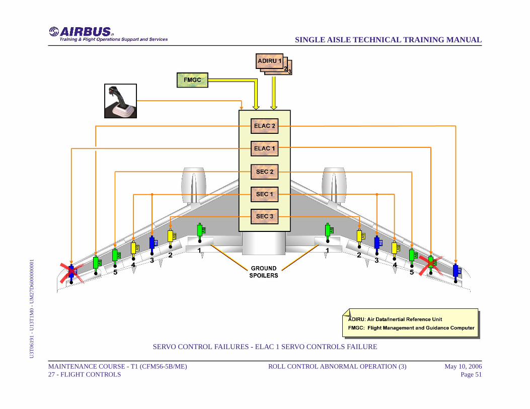
SERVO CONTROL FAILURES (continued)
ELAC 1 SERVO CONTROLS FAILUREIn case of failure of both ELAC 1 servo controls, then ELAC 2 doesthe computation and controls its servo controls.
MAINTENANCE COURSE - T1 (CFM56-5B/ME) 27 - FLIGHT CONTROLS
ROLL CONTROL ABNORMAL OPERATION (3) May 10, 2006Page 50
SINGLE AISLE TECHNICAL TRAINING MANUALU
3T06
191
- U
13T
1M0
- U
M27
D60
0000
0001
SERVO CONTROL FAILURES - ELAC 1 SERVO CONTROLS FAILURE
MAINTENANCE COURSE - T1 (CFM56-5B/ME) 27 - FLIGHT CONTROLS
ROLL CONTROL ABNORMAL OPERATION (3) May 10, 2006Page 51
SINGLE AISLE TECHNICAL TRAINING MANUALU
3T06
191
- U
13T
1M0
- U
M27
D60
0000
0001

ROLL CONTROL ABNORMAL OPERATION (3)
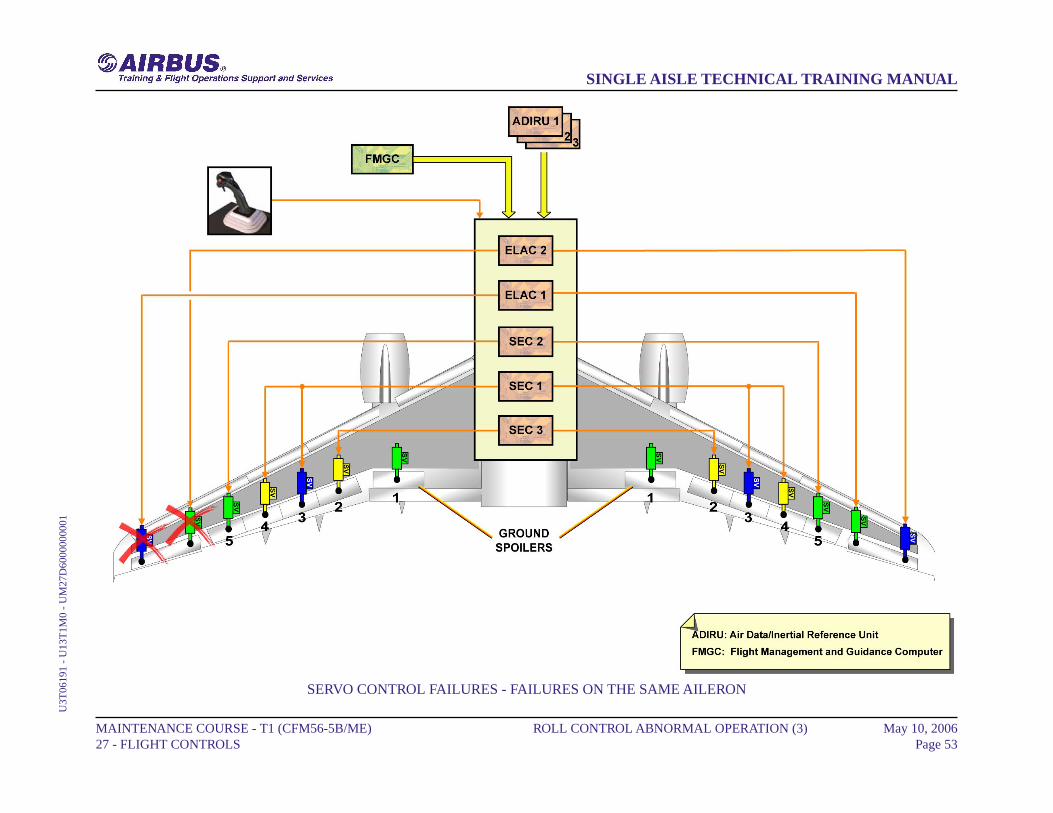
SERVO CONTROL FAILURES (continued)
FAILURES ON THE SAME AILERONIn case of failure of both servo controls of the same aileron, the otheraileron is still operated.
MAINTENANCE COURSE - T1 (CFM56-5B/ME) 27 - FLIGHT CONTROLS
ROLL CONTROL ABNORMAL OPERATION (3) May 10, 2006Page 52
SINGLE AISLE TECHNICAL TRAINING MANUALU
3T06
191
- U
13T
1M0
- U
M27
D60
0000
0001
SERVO CONTROL FAILURES - FAILURES ON THE SAME AILERON
MAINTENANCE COURSE - T1 (CFM56-5B/ME) 27 - FLIGHT CONTROLS
ROLL CONTROL ABNORMAL OPERATION (3) May 10, 2006Page 53
SINGLE AISLE TECHNICAL TRAINING MANUALU
3T06
191
- U
13T
1M0
- U
M27
D60
0000
0001
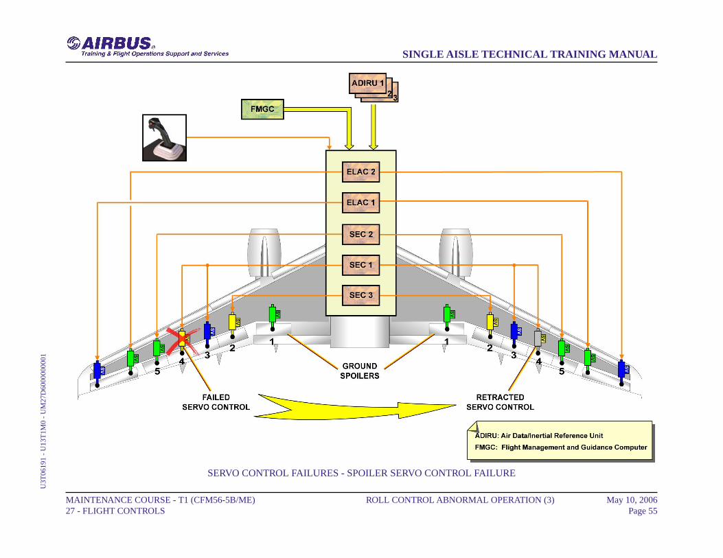
ROLL CONTROL ABNORMAL OPERATION (3)
SERVO CONTROL FAILURES (continued)
SPOILER SERVO CONTROL FAILUREIn case of failure of a spoiler servo control, the opposite surface isretracted.
MAINTENANCE COURSE - T1 (CFM56-5B/ME) 27 - FLIGHT CONTROLS
ROLL CONTROL ABNORMAL OPERATION (3) May 10, 2006Page 54
SINGLE AISLE TECHNICAL TRAINING MANUALU
3T06
191
- U
13T
1M0
- U
M27
D60
0000
0001
SERVO CONTROL FAILURES - SPOILER SERVO CONTROL FAILURE
MAINTENANCE COURSE - T1 (CFM56-5B/ME) 27 - FLIGHT CONTROLS
ROLL CONTROL ABNORMAL OPERATION (3) May 10, 2006Page 55
SINGLE AISLE TECHNICAL TRAINING MANUALU
3T06
191
- U
13T
1M0
- U
M27
D60
0000
0001
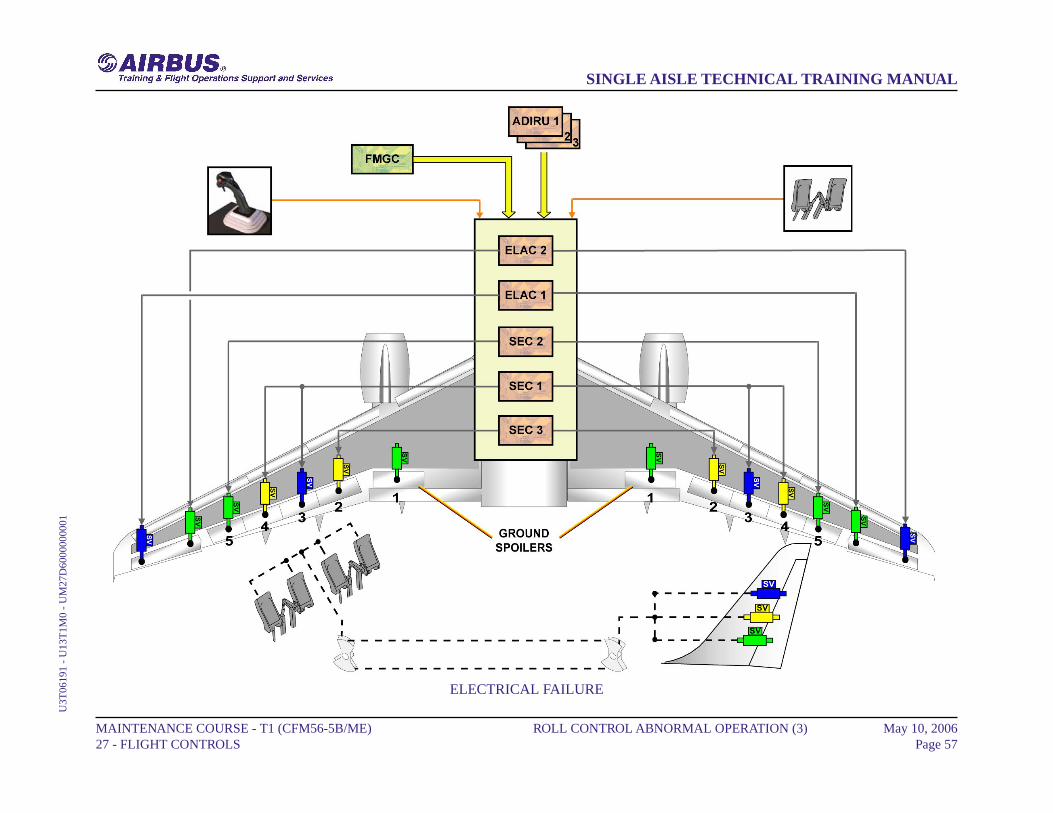
ROLL CONTROL ABNORMAL OPERATION (3)
ELECTRICAL FAILURE
In case of total electrical loss, induced roll is obtained by using the rudderpedals, which have a mechanical control.
MAINTENANCE COURSE - T1 (CFM56-5B/ME) 27 - FLIGHT CONTROLS
ROLL CONTROL ABNORMAL OPERATION (3) May 10, 2006Page 56
SINGLE AISLE TECHNICAL TRAINING MANUALU
3T06
191
- U
13T
1M0
- U
M27
D60
0000
0001
ELECTRICAL FAILURE
MAINTENANCE COURSE - T1 (CFM56-5B/ME) 27 - FLIGHT CONTROLS
ROLL CONTROL ABNORMAL OPERATION (3) May 10, 2006Page 57
SINGLE AISLE TECHNICAL TRAINING MANUALU
3T06
191
- U
13T
1M0
- U
M27
D60
0000
0001
YAW CONTROL NORMAL D/O (3)
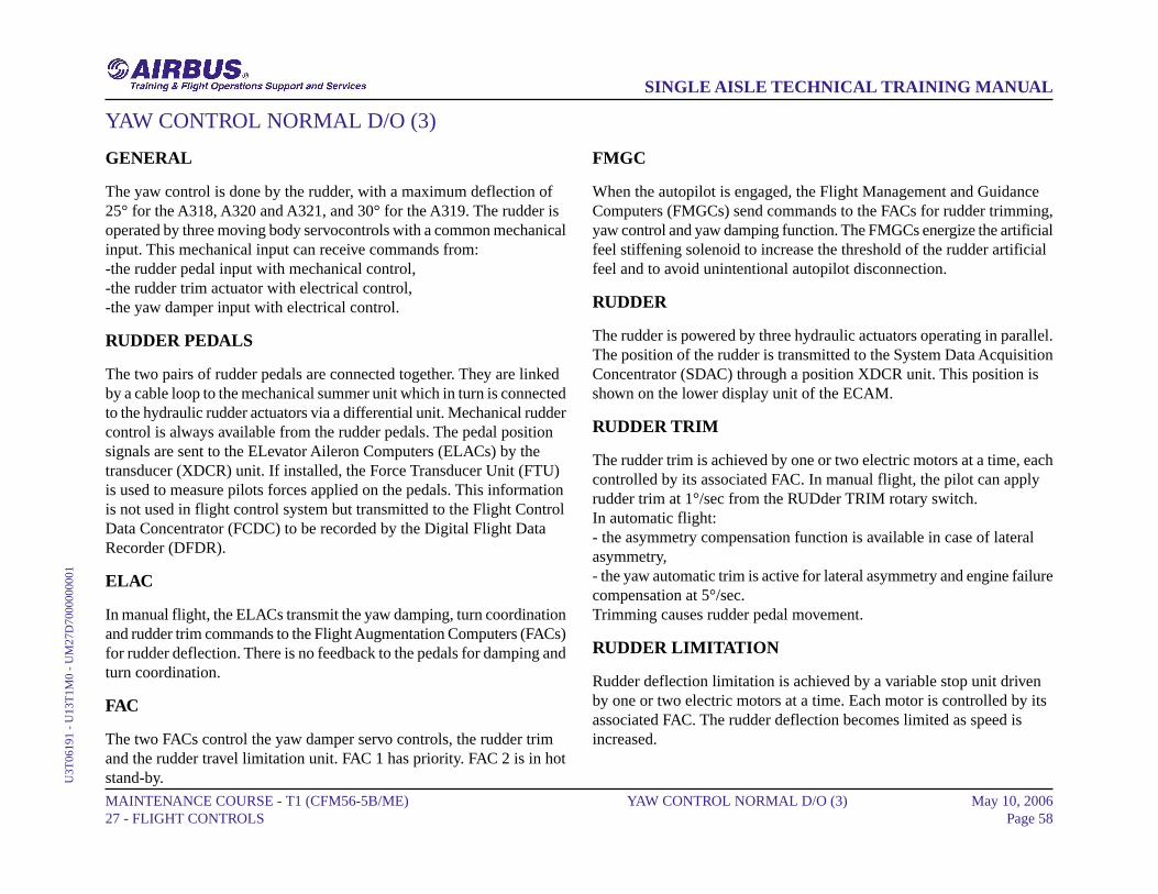
GENERAL
The yaw control is done by the rudder, with a maximum deflection of25° for the A318, A320 and A321, and 30° for the A319. The rudder isoperated by three moving body servocontrols with a common mechanicalinput. This mechanical input can receive commands from:-the rudder pedal input with mechanical control,-the rudder trim actuator with electrical control,-the yaw damper input with electrical control.
RUDDER PEDALS
The two pairs of rudder pedals are connected together. They are linkedby a cable loop to the mechanical summer unit which in turn is connectedto the hydraulic rudder actuators via a differential unit. Mechanical ruddercontrol is always available from the rudder pedals. The pedal positionsignals are sent to the ELevator Aileron Computers (ELACs) by thetransducer (XDCR) unit. If installed, the Force Transducer Unit (FTU)is used to measure pilots forces applied on the pedals. This informationis not used in flight control system but transmitted to the Flight ControlData Concentrator (FCDC) to be recorded by the Digital Flight DataRecorder (DFDR).
ELAC
In manual flight, the ELACs transmit the yaw damping, turn coordinationand rudder trim commands to the Flight Augmentation Computers (FACs)for rudder deflection. There is no feedback to the pedals for damping andturn coordination.
FAC
The two FACs control the yaw damper servo controls, the rudder trimand the rudder travel limitation unit. FAC 1 has priority. FAC 2 is in hotstand-by.
FMGC
When the autopilot is engaged, the Flight Management and GuidanceComputers (FMGCs) send commands to the FACs for rudder trimming,yaw control and yaw damping function. The FMGCs energize the artificialfeel stiffening solenoid to increase the threshold of the rudder artificialfeel and to avoid unintentional autopilot disconnection.
RUDDER
The rudder is powered by three hydraulic actuators operating in parallel.The position of the rudder is transmitted to the System Data AcquisitionConcentrator (SDAC) through a position XDCR unit. This position isshown on the lower display unit of the ECAM.
RUDDER TRIM
The rudder trim is achieved by one or two electric motors at a time, eachcontrolled by its associated FAC. In manual flight, the pilot can applyrudder trim at 1°/sec from the RUDder TRIM rotary switch.In automatic flight:- the asymmetry compensation function is available in case of lateralasymmetry,- the yaw automatic trim is active for lateral asymmetry and engine failurecompensation at 5°/sec.Trimming causes rudder pedal movement.
RUDDER LIMITATION
Rudder deflection limitation is achieved by a variable stop unit drivenby one or two electric motors at a time. Each motor is controlled by itsassociated FAC. The rudder deflection becomes limited as speed isincreased.
MAINTENANCE COURSE - T1 (CFM56-5B/ME) 27 - FLIGHT CONTROLS
YAW CONTROL NORMAL D/O (3) May 10, 2006Page 58
SINGLE AISLE TECHNICAL TRAINING MANUALU
3T06
191
- U
13T
1M0
- U
M27
D70
0000
0001
YAW DAMPING
One or two yaw dampers servo activation controls are connected to therudder hydraulic actuators through a mechanical differential unit: eachservo actuator is controlled by its related FAC. No feedback to the rudderpedals is given thanks to the differential unit.
MAINTENANCE COURSE - T1 (CFM56-5B/ME) 27 - FLIGHT CONTROLS
YAW CONTROL NORMAL D/O (3) May 10, 2006Page 59
SINGLE AISLE TECHNICAL TRAINING MANUALU
3T06
191
- U
13T
1M0
- U
M27
D70
0000
0001

GENERAL ... YAW DAMPING
MAINTENANCE COURSE - T1 (CFM56-5B/ME) 27 - FLIGHT CONTROLS
YAW CONTROL NORMAL D/O (3) May 10, 2006Page 60
SINGLE AISLE TECHNICAL TRAINING MANUALU
3T06
191
- U
13T
1M0
- U
M27
D70
0000
0001
This Page Intentionally Left Blank
MAINTENANCE COURSE - T1 (CFM56-5B/ME) 27 - FLIGHT CONTROLS
YAW CONTROL NORMAL D/O (3) May 10, 2006Page 61
SINGLE AISLE TECHNICAL TRAINING MANUALU
3T06
191
- U
13T
1M0
- U
M27
D70
0000
0001
YAW CONTROL ABNORMAL D/O (3)
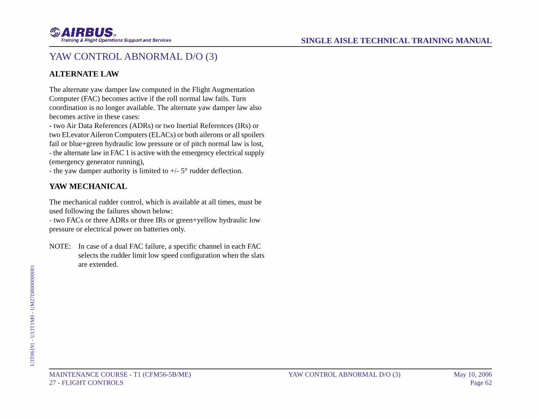
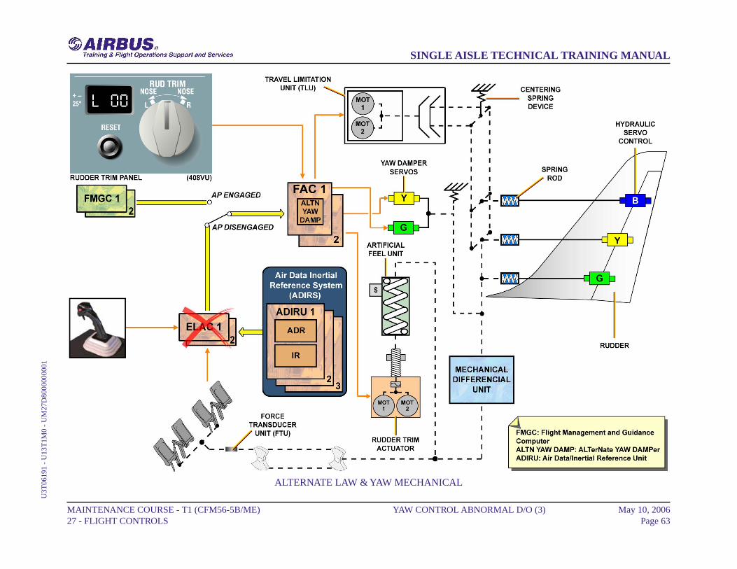
ALTERNATE LAW
The alternate yaw damper law computed in the Flight AugmentationComputer (FAC) becomes active if the roll normal law fails. Turncoordination is no longer available. The alternate yaw damper law alsobecomes active in these cases:- two Air Data References (ADRs) or two Inertial References (IRs) ortwo ELevator Aileron Computers (ELACs) or both ailerons or all spoilersfail or blue+green hydraulic low pressure or of pitch normal law is lost,- the alternate law in FAC 1 is active with the emergency electrical supply(emergency generator running),- the yaw damper authority is limited to +/- 5° rudder deflection.
YAW MECHANICAL
The mechanical rudder control, which is available at all times, must beused following the failures shown below:- two FACs or three ADRs or three IRs or green+yellow hydraulic lowpressure or electrical power on batteries only.
NOTE: In case of a dual FAC failure, a specific channel in each FACselects the rudder limit low speed configuration when the slatsare extended.
MAINTENANCE COURSE - T1 (CFM56-5B/ME) 27 - FLIGHT CONTROLS
YAW CONTROL ABNORMAL D/O (3) May 10, 2006Page 62
SINGLE AISLE TECHNICAL TRAINING MANUALU
3T06
191
- U
13T
1M0
- U
M27
D80
0000
0001
ALTERNATE LAW & YAW MECHANICAL
MAINTENANCE COURSE - T1 (CFM56-5B/ME) 27 - FLIGHT CONTROLS
YAW CONTROL ABNORMAL D/O (3) May 10, 2006Page 63
SINGLE AISLE TECHNICAL TRAINING MANUALU
3T06
191
- U
13T
1M0
- U
M27
D80
0000
0001
AILERON SERVO CONTROL OPERATION (3)
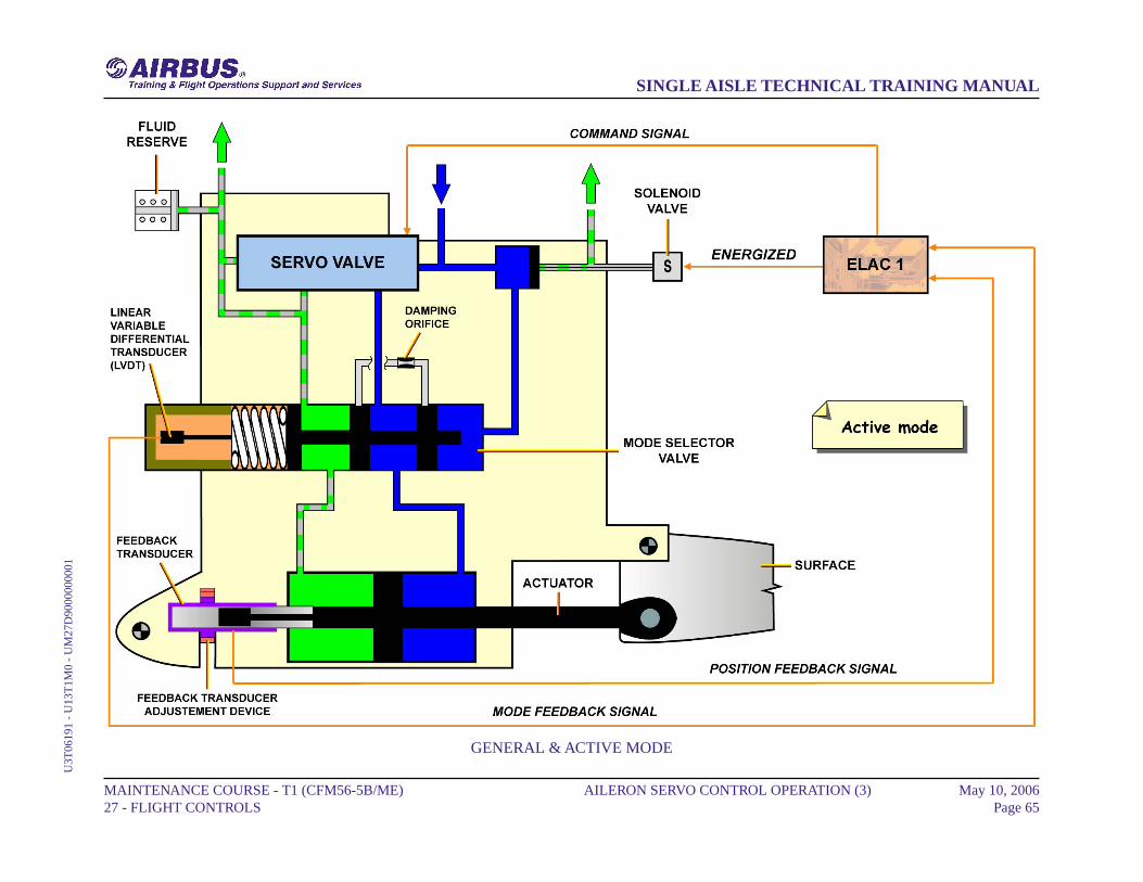
GENERAL
Each aileron is equipped with two identical electro-hydraulicservo-controls. These servo-controls have two modes:- the active mode- the damping mode.
ACTIVE MODE
In the active mode, the solenoid valve is energized by the ELevatorAileron Computer (ELAC). This enables the HP fluid to flow and to putthe mode selector valve in the active position. The two chambers of theactuator are thus connected to the servo-valve control lines. Theservo-control is then in the active mode. The Linear Variable-DifferentialTransducer (LVDT) supplies an electrical signal to the ELAC, whichidentifies this change of state. The feedback transducer (also calledLVDT) gives the servo-loop feedback.
MAINTENANCE COURSE - T1 (CFM56-5B/ME) 27 - FLIGHT CONTROLS
AILERON SERVO CONTROL OPERATION (3) May 10, 2006Page 64
SINGLE AISLE TECHNICAL TRAINING MANUALU
3T06
191
- U
13T
1M0
- U
M27
D90
0000
0001
GENERAL & ACTIVE MODE
MAINTENANCE COURSE - T1 (CFM56-5B/ME) 27 - FLIGHT CONTROLS
AILERON SERVO CONTROL OPERATION (3) May 10, 2006Page 65
SINGLE AISLE TECHNICAL TRAINING MANUALU
3T06
191
- U
13T
1M0
- U
M27
D90
0000
0001
AILERON SERVO CONTROL OPERATION (3)
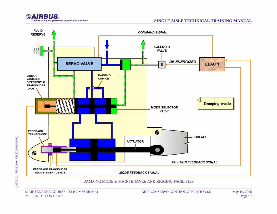
DAMPING MODE
In damping mode, the actuator follows the control surface movements.In this configuration, the solenoid valve is de-energized and the modeselector valve moves under the action of its spring. The two chambersof the actuator are thus interconnected through the damping orifice. TheLVDT identifies this change of state and transmit it to the ELAC. Thefluid reserve allows to hold the volume of fluid in the actuator chambers:- if the temperature of the hydraulic fluid changes or,- if there is a leakage.The fluid reserve is permanently connected to the return line of theservo-valve.
MAINTENANCE AND RIGGING FACILITIES
After replacement of the servo-control, it is necessary to adjust thefeedback transducer (LVDT). It is necessary to get an equal voltage inthe secondary winding (electrical zero) when the aileron is in neutralposition. This is done through an action on the feedback transduceradjustment device located on the actuator.
MAINTENANCE COURSE - T1 (CFM56-5B/ME) 27 - FLIGHT CONTROLS
AILERON SERVO CONTROL OPERATION (3) May 10, 2006Page 66
SINGLE AISLE TECHNICAL TRAINING MANUALU
3T06
191
- U
13T
1M0
- U
M27
D90
0000
0001
DAMPING MODE & MAINTENANCE AND RIGGING FACILITIES
MAINTENANCE COURSE - T1 (CFM56-5B/ME) 27 - FLIGHT CONTROLS
AILERON SERVO CONTROL OPERATION (3) May 10, 2006Page 67
SINGLE AISLE TECHNICAL TRAINING MANUALU
3T06
191
- U
13T
1M0
- U
M27
D90
0000
0001
SPOILER SERVO CONTROL OPERATION (3)
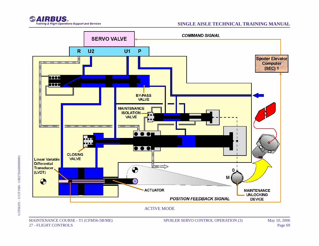
ACTIVE MODE
In active mode the spoiler servo control actuator is hydraulically supplied.According to the command signal to the servo valve the spoiler surfacewill extend or retract. The feedback transducer Linear VariableDifferential Transducer (LVDT) provide(s) the servo loop feedback.
MAINTENANCE COURSE - T1 (CFM56-5B/ME) 27 - FLIGHT CONTROLS
SPOILER SERVO CONTROL OPERATION (3) May 10, 2006Page 68
SINGLE AISLE TECHNICAL TRAINING MANUALU
3T06
191
- U
13T
1M0
- U
M27
DA
0000
0000
1
ACTIVE MODE
MAINTENANCE COURSE - T1 (CFM56-5B/ME) 27 - FLIGHT CONTROLS
SPOILER SERVO CONTROL OPERATION (3) May 10, 2006Page 69
SINGLE AISLE TECHNICAL TRAINING MANUALU
3T06
191
- U
13T
1M0
- U
M27
DA
0000
0000
1
SPOILER SERVO CONTROL OPERATION (3)
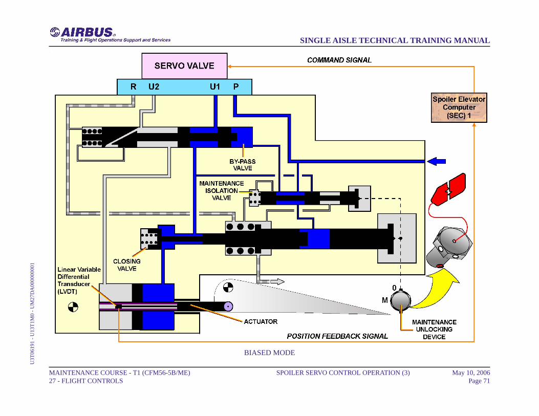
BIASED MODE
The servo-control actuator is pressurized. Due to an electrical failure thecommand signal is lost. The biased servo valve pressurizes the retractionchamber. The spoiler actuator stays pressurized and the spoiler remainsretracted.
MAINTENANCE COURSE - T1 (CFM56-5B/ME) 27 - FLIGHT CONTROLS
SPOILER SERVO CONTROL OPERATION (3) May 10, 2006Page 70
SINGLE AISLE TECHNICAL TRAINING MANUALU
3T06
191
- U
13T
1M0
- U
M27
DA
0000
0000
1
BIASED MODE
MAINTENANCE COURSE - T1 (CFM56-5B/ME) 27 - FLIGHT CONTROLS
SPOILER SERVO CONTROL OPERATION (3) May 10, 2006Page 71
SINGLE AISLE TECHNICAL TRAINING MANUALU
3T06
191
- U
13T
1M0
- U
M27
DA
0000
0000
1
SPOILER SERVO CONTROL OPERATION (3)
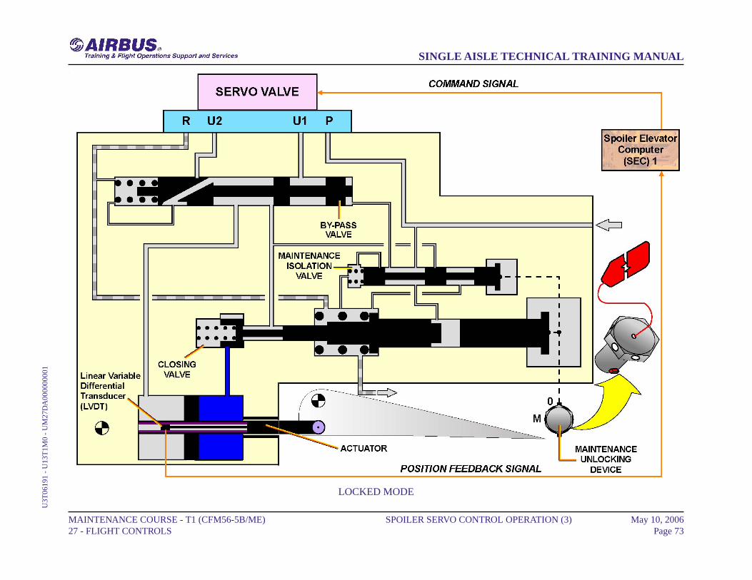
LOCKED MODE
In locked mode, the hydraulic pressure is lost. The closing valve closesthe retraction chamber. The surface can only be moved towards theretracted position, pushed by aerodynamical forces.
MAINTENANCE COURSE - T1 (CFM56-5B/ME) 27 - FLIGHT CONTROLS
SPOILER SERVO CONTROL OPERATION (3) May 10, 2006Page 72
SINGLE AISLE TECHNICAL TRAINING MANUALU
3T06
191
- U
13T
1M0
- U
M27
DA
0000
0000
1
LOCKED MODE
MAINTENANCE COURSE - T1 (CFM56-5B/ME) 27 - FLIGHT CONTROLS
SPOILER SERVO CONTROL OPERATION (3) May 10, 2006Page 73
SINGLE AISLE TECHNICAL TRAINING MANUALU
3T06
191
- U
13T
1M0
- U
M27
DA
0000
0000
1
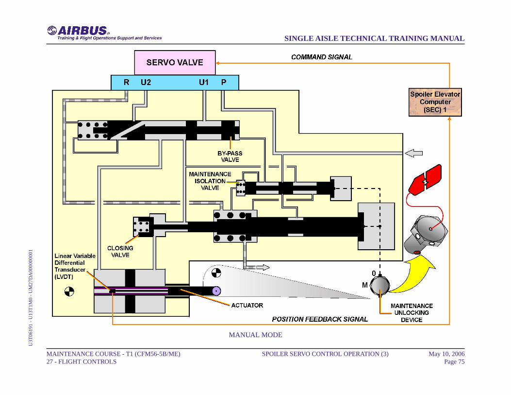
SPOILER SERVO CONTROL OPERATION (3)
MANUAL MODE
To be unlocked, the servo control actuator must be depressurized. Themaintenance unlocking device can be engaged thanks to a key equippedwith a red flame. This tool cannot be removed when the servo control isin maintenance mode. Once the maintenance unlocking device is engagedthe spoiler surface can be raised manually for inspection purposes.
MAINTENANCE COURSE - T1 (CFM56-5B/ME) 27 - FLIGHT CONTROLS
SPOILER SERVO CONTROL OPERATION (3) May 10, 2006Page 74
SINGLE AISLE TECHNICAL TRAINING MANUALU
3T06
191
- U
13T
1M0
- U
M27
DA
0000
0000
1
MANUAL MODE
MAINTENANCE COURSE - T1 (CFM56-5B/ME) 27 - FLIGHT CONTROLS
SPOILER SERVO CONTROL OPERATION (3) May 10, 2006Page 75
SINGLE AISLE TECHNICAL TRAINING MANUALU
3T06
191
- U
13T
1M0
- U
M27
DA
0000
0000
1
RUDDER TRIM ACTUATOR D/O (3)
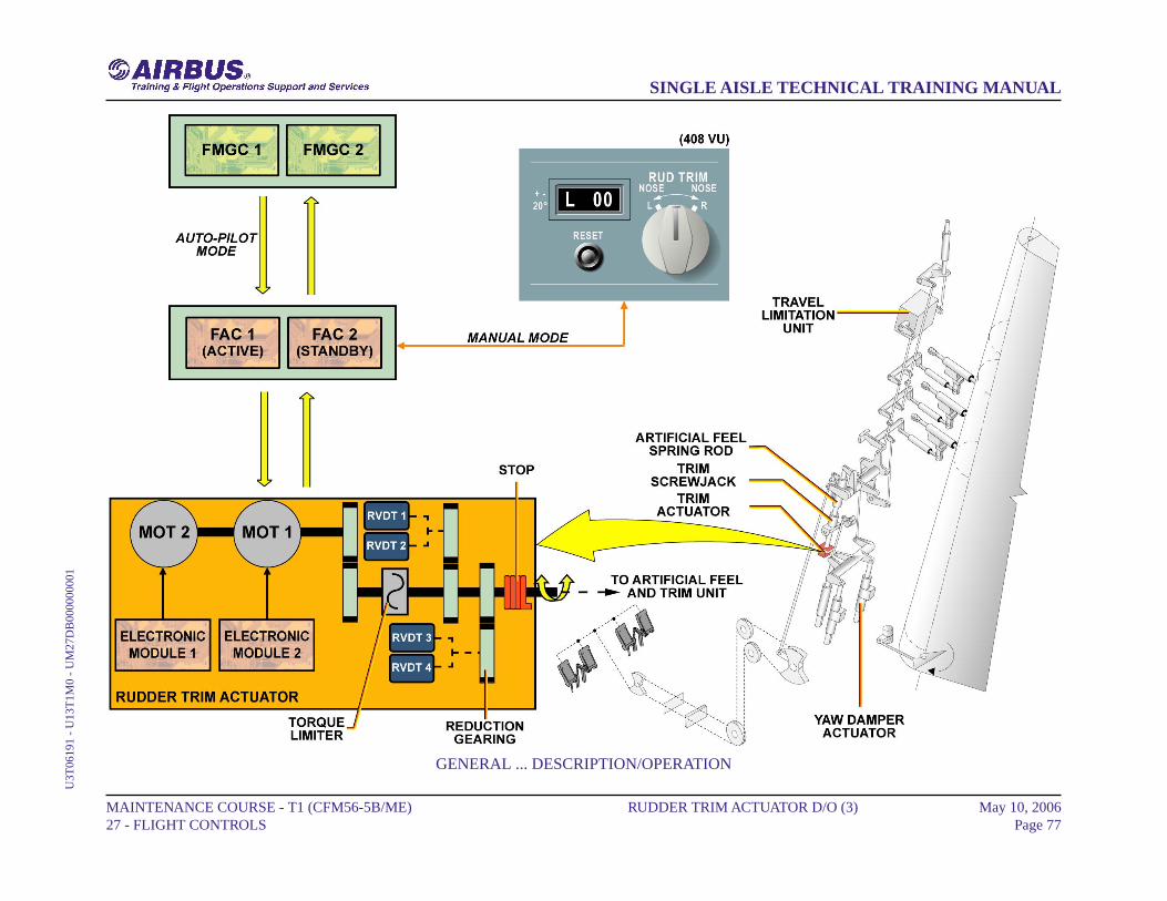
GENERAL
The rudder trim actuator is installed on the rudder system, in the tail areaand is one of the mechanical inputs of the rudder servocontrols. Therudder trim actuator enables the zero force position of the artificial feeland trim unit to be adjusted.
CONTROLS
The rudder trim actuator is an electromechanical unit, which convertsthe electrical input from the Flight Augmentation Computers (FACs)into a rotation of its output shaft. The rudder trim actuator can becontrolled either by the RUDder TRIM control switch located in thecenter pedestal of the cockpit, in manual mode, or by the FlightManagement & Guidance Computers (FMGCs) in AP mode. In bothcases orders are sent via the FACs. In automatic control, the rudder trimfunction controlled by the FAC, fulfills the generation and theaccomplishment of the engine failure recovery function. In this case, theengine failure compensation slow law orders are sent to the rudder trimactuator. The AP also provides signals, which validate the detection ofengine failure as a function of the engine rating.
DESCRIPTION/OPERATION
The rudder trim actuator has two DC motors, installed on the same shaft.Each one is controlled by one independent electronic module, with onlyone motor operating at a time, via FAC1 or 2. The motors permanentlycoupled to a reduction gear, drive the output shaft, via a torque limiter.Then the output shaft drives four Rotary Variable Differential Transducers(RVDTs), transmitting the output shaft position signal to the FACs.
MAINTENANCE COURSE - T1 (CFM56-5B/ME) 27 - FLIGHT CONTROLS
RUDDER TRIM ACTUATOR D/O (3) May 10, 2006Page 76
SINGLE AISLE TECHNICAL TRAINING MANUALU
3T06
191
- U
13T
1M0
- U
M27
DB
0000
0000
1
GENERAL ... DESCRIPTION/OPERATION
MAINTENANCE COURSE - T1 (CFM56-5B/ME) 27 - FLIGHT CONTROLS
RUDDER TRIM ACTUATOR D/O (3) May 10, 2006Page 77
SINGLE AISLE TECHNICAL TRAINING MANUALU
3T06
191
- U
13T
1M0
- U
M27
DB
0000
0000
1
RUDDER SERVO CONTROL OPERATION (3)
ACTIVE MODE
When the rudder servo control actuator is in active mode, the actuatormoves to the right or to the left according to the control valve position.The high pressure is connected to the return via the heating orifice; thisfulfills the permanent heating leakage.
MAINTENANCE COURSE - T1 (CFM56-5B/ME) 27 - FLIGHT CONTROLS
RUDDER SERVO CONTROL OPERATION (3) May 10, 2006Page 78
SINGLE AISLE TECHNICAL TRAINING MANUALU
3T06
191
- U
13T
1M0
- U
M27
DC
0000
0000
1
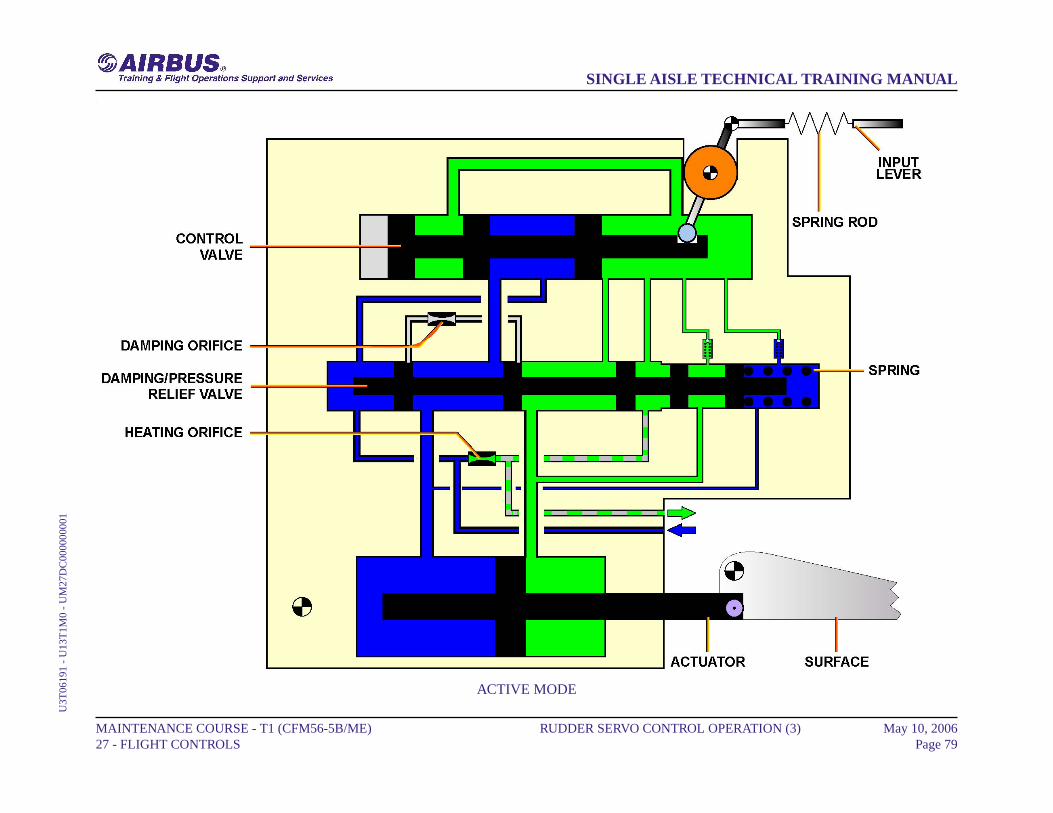
ACTIVE MODE
MAINTENANCE COURSE - T1 (CFM56-5B/ME) 27 - FLIGHT CONTROLS
RUDDER SERVO CONTROL OPERATION (3) May 10, 2006Page 79
SINGLE AISLE TECHNICAL TRAINING MANUALU
3T06
191
- U
13T
1M0
- U
M27
DC
0000
0000
1
RUDDER SERVO CONTROL OPERATION (3)
DAMPING MODE
The rudder servo control actuator changes to damping mode, as soon asthe hydraulic pressure supply is cut. When the servo control isdepressurized, the spring sets the damping and pressure-relief valve tothe bypass position, and the hydraulic fluid goes from one chamber tothe other via the damping orifice.
MAINTENANCE COURSE - T1 (CFM56-5B/ME) 27 - FLIGHT CONTROLS
RUDDER SERVO CONTROL OPERATION (3) May 10, 2006Page 80
SINGLE AISLE TECHNICAL TRAINING MANUALU
3T06
191
- U
13T
1M0
- U
M27
DC
0000
0000
1
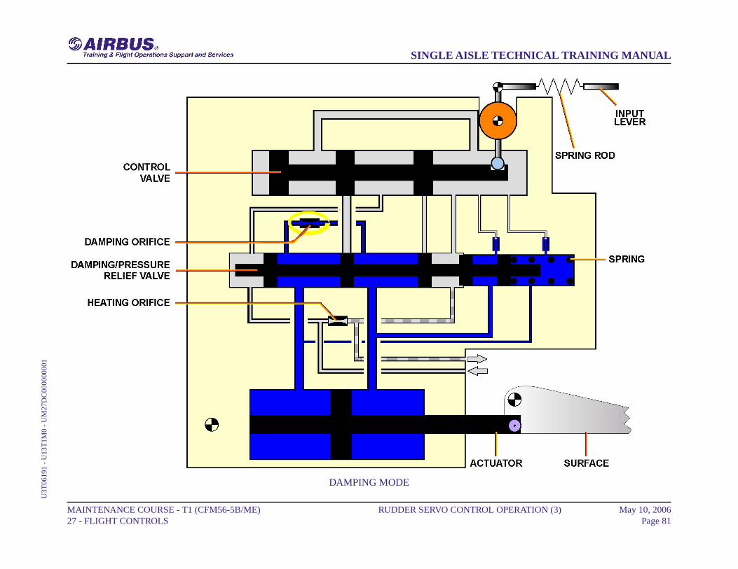
DAMPING MODE
MAINTENANCE COURSE - T1 (CFM56-5B/ME) 27 - FLIGHT CONTROLS
RUDDER SERVO CONTROL OPERATION (3) May 10, 2006Page 81
SINGLE AISLE TECHNICAL TRAINING MANUALU
3T06
191
- U
13T
1M0
- U
M27
DC
0000
0000
1
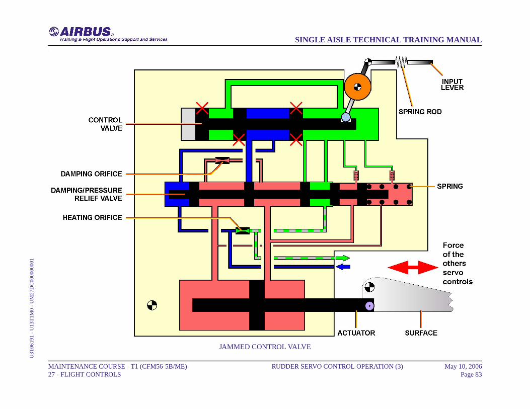
RUDDER SERVO CONTROL OPERATION (3)
JAMMED CONTROL VALVE
If the control valve jams, the rudder servo control actuator follows therudder surface movement, ensured by the other rudder servo controls.Rudder locking or runaway in the event of a servo control valve jammingis prevented by a spring rod and pressure relief valve arrangement.
MAINTENANCE COURSE - T1 (CFM56-5B/ME) 27 - FLIGHT CONTROLS
RUDDER SERVO CONTROL OPERATION (3) May 10, 2006Page 82
SINGLE AISLE TECHNICAL TRAINING MANUALU
3T06
191
- U
13T
1M0
- U
M27
DC
0000
0000
1
JAMMED CONTROL VALVE
MAINTENANCE COURSE - T1 (CFM56-5B/ME) 27 - FLIGHT CONTROLS
RUDDER SERVO CONTROL OPERATION (3) May 10, 2006Page 83
SINGLE AISLE TECHNICAL TRAINING MANUALU
3T06
191
- U
13T
1M0
- U
M27
DC
0000
0000
1
RUDDER LIMITER OPERATION (3)
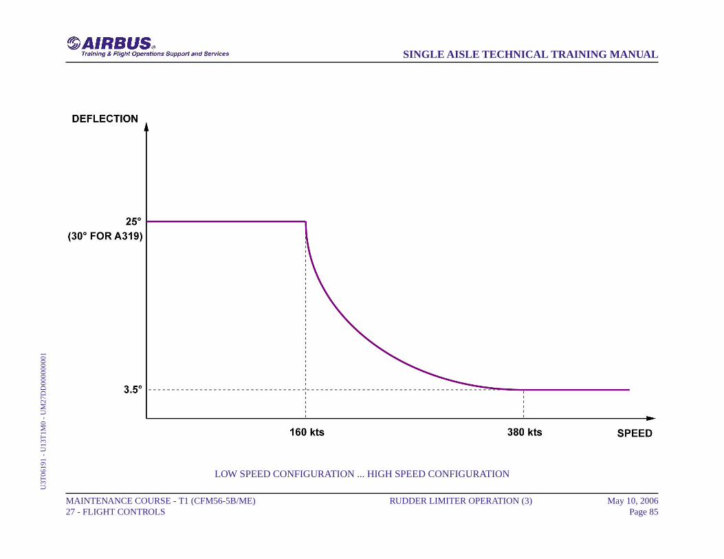
LOW SPEED CONFIGURATION
Under 160 kts the stops are in low-speed configuration. Full input/outputlever movement to the rudder servo control is available.
VARIABLE LIMITATION
Between 160 and 380 kts the rudder deflection is limited as a functionof speed. The corresponding law is computed by the Flight AugmentationComputers (FACs).
HIGH SPEED CONFIGURATION
Above 380 kts the stops are in high-speed configuration. Only limitedinput/output lever movement to the rudder servo control is available.
MAINTENANCE COURSE - T1 (CFM56-5B/ME) 27 - FLIGHT CONTROLS
RUDDER LIMITER OPERATION (3) May 10, 2006Page 84
SINGLE AISLE TECHNICAL TRAINING MANUALU
3T06
191
- U
13T
1M0
- U
M27
DD
0000
0000
1
LOW SPEED CONFIGURATION ... HIGH SPEED CONFIGURATION
MAINTENANCE COURSE - T1 (CFM56-5B/ME) 27 - FLIGHT CONTROLS
RUDDER LIMITER OPERATION (3) May 10, 2006Page 85
SINGLE AISLE TECHNICAL TRAINING MANUALU
3T06
191
- U
13T
1M0
- U
M27
DD
0000
0000
1

RUDDER LIMITER OPERATION (3)
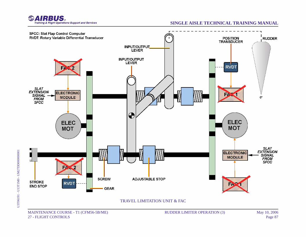
TRAVEL LIMITATION UNIT
The mechanical design of the Travel Limitation Unit (TLU) is such thata single mechanical failure (rupture or disconnection) cannot cause theloss of the travel limitation function. The TLU has two brushless electricmotors separately controlled by an electronic assembly. Each motor drivestwo screws via a reduction gear and permits the symmetrical lineardisplacement of two nuts used as adjustable stops. A non-locking rotarystop limits the stroke of one of the screw/nut assemblies which areirreversible. There are two levers on each connection shaft; one isconnected to the input rod and the other is used as a punctual stop. Themovement of each screw is transmitted to a Rotary Variable DifferentialTransducer via the reduction gear which permits to indicate the positionof the variable stop.
NOTE: Note: To prevent icing, there is a heating system which includestwo coils and their regulating thermostats.
FAC
If both FACs fail, the rudder travel limitation value is frozen immediately.In this case, an emergency control brings back the stops to the low speedconfiguration (maximum possible deflection of the rudder) when slatsare extended.
NOTE: Note: To bring back the stops to the low speed configuration,the motors are used as 2-phase asynchronous motor energizedby 26V 400 Hz power. This control mode is achieved when thecoil of a specific relay ( each motor has a relay ) is energizedfor a period of 30 s approximately. This time is sufficient tobring back the stops to the low speed configuration.
MAINTENANCE COURSE - T1 (CFM56-5B/ME) 27 - FLIGHT CONTROLS
RUDDER LIMITER OPERATION (3) May 10, 2006Page 86
SINGLE AISLE TECHNICAL TRAINING MANUALU
3T06
191
- U
13T
1M0
- U
M27
DD
0000
0000
1
TRAVEL LIMITATION UNIT & FAC
MAINTENANCE COURSE - T1 (CFM56-5B/ME) 27 - FLIGHT CONTROLS
RUDDER LIMITER OPERATION (3) May 10, 2006Page 87
SINGLE AISLE TECHNICAL TRAINING MANUALU
3T06
191
- U
13T
1M0
- U
M27
DD
0000
0000
1
YAW DAMPER SERVO ACTUATOR OPERATION (3)
ACTIVE MODE
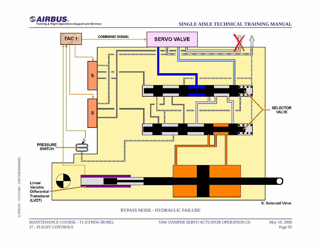
The actuator is in active mode when both solenoid valves are energized;,the hydraulic pressure and the servo valve are available. The two selectorvalves are connected to the servovalve outputs and allow the servoactuator to operate in active mode. In this case the pressure switch is notactivated. The feedback transducer of the Linear Variable DifferentialTransducer (LVDT) type , supplies the servo loop feedback informationto the Flight Augmentation Computers (FACs). FAC 1 controls andmonitors the green servo actuator and FAC 2 the yellow one. Only oneyaw damper at a time is in active mode, the other one is in a by-passmode.
MONITORING
A pressure switch installed on to the servo actuator detects any differentposition between the selector valves.
MAINTENANCE COURSE - T1 (CFM56-5B/ME) 27 - FLIGHT CONTROLS
YAW DAMPER SERVO ACTUATOR OPERATION (3) May 10, 2006Page 88
SINGLE AISLE TECHNICAL TRAINING MANUALU
3T06
191
- U
13T
1M0
- U
M27
DE
0000
0000
1

ACTIVE MODE & MONITORING
MAINTENANCE COURSE - T1 (CFM56-5B/ME) 27 - FLIGHT CONTROLS
YAW DAMPER SERVO ACTUATOR OPERATION (3) May 10, 2006Page 89
SINGLE AISLE TECHNICAL TRAINING MANUALU
3T06
191
- U
13T
1M0
- U
M27
DE
0000
0000
1

YAW DAMPER SERVO ACTUATOR OPERATION (3)
BYPASS MODE
BOTH SOLENOID VALVES DE-ENERGIZEDThe two-solenoid valves are de-energized and the associated selectorvalves are set to the bypass mode under the action of their spring. Thetwo-piston chambers are, in this case, interconnected. The pressureswitch is not activated.
MAINTENANCE COURSE - T1 (CFM56-5B/ME) 27 - FLIGHT CONTROLS
YAW DAMPER SERVO ACTUATOR OPERATION (3) May 10, 2006Page 90
SINGLE AISLE TECHNICAL TRAINING MANUALU
3T06
191
- U
13T
1M0
- U
M27
DE
0000
0000
1

BYPASS MODE - BOTH SOLENOID VALVES DE-ENERGIZED
MAINTENANCE COURSE - T1 (CFM56-5B/ME) 27 - FLIGHT CONTROLS
YAW DAMPER SERVO ACTUATOR OPERATION (3) May 10, 2006Page 91
SINGLE AISLE TECHNICAL TRAINING MANUALU
3T06
191
- U
13T
1M0
- U
M27
DE
0000
0000
1
YAW DAMPER SERVO ACTUATOR OPERATION (3)
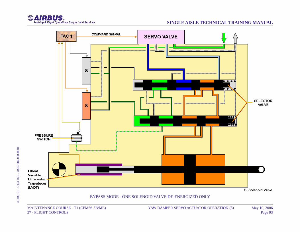
BYPASS MODE (continued)
ONE SOLENOID VALVE DE-ENERGIZED ONLYIn case of a single electrical failure causing one selector valve to bein bypass mode, the other being in active mode, the result lies in theinterconnection of the two actuator chambers, thus the actuator is inbypass mode. In this way, by means of the pressure switch, which isnow connected to the supply pressure, this abnormal configuration isindicated to the FACs.
MAINTENANCE COURSE - T1 (CFM56-5B/ME) 27 - FLIGHT CONTROLS
YAW DAMPER SERVO ACTUATOR OPERATION (3) May 10, 2006Page 92
SINGLE AISLE TECHNICAL TRAINING MANUALU
3T06
191
- U
13T
1M0
- U
M27
DE
0000
0000
1
BYPASS MODE - ONE SOLENOID VALVE DE-ENERGIZED ONLY
MAINTENANCE COURSE - T1 (CFM56-5B/ME) 27 - FLIGHT CONTROLS
YAW DAMPER SERVO ACTUATOR OPERATION (3) May 10, 2006Page 93
SINGLE AISLE TECHNICAL TRAINING MANUALU
3T06
191
- U
13T
1M0
- U
M27
DE
0000
0000
1
YAW DAMPER SERVO ACTUATOR OPERATION (3)
BYPASS MODE (continued)
HYDRAULIC FAILUREWith no hydraulic pressure, the two selector valves are set, under theaction of their spring, in bypass mode, thus the two chambers of thepiston are interconnected. In this case, the pressure switch is notactivated.
MAINTENANCE COURSE - T1 (CFM56-5B/ME) 27 - FLIGHT CONTROLS
YAW DAMPER SERVO ACTUATOR OPERATION (3) May 10, 2006Page 94
SINGLE AISLE TECHNICAL TRAINING MANUALU
3T06
191
- U
13T
1M0
- U
M27
DE
0000
0000
1
BYPASS MODE - HYDRAULIC FAILURE
MAINTENANCE COURSE - T1 (CFM56-5B/ME) 27 - FLIGHT CONTROLS
YAW DAMPER SERVO ACTUATOR OPERATION (3) May 10, 2006Page 95
SINGLE AISLE TECHNICAL TRAINING MANUALU
3T06
191
- U
13T
1M0
- U
M27
DE
0000
0000
1
SPEED BRAKE & GROUND SPOILER D/O (3)
SPEED BRAKE FUNCTION
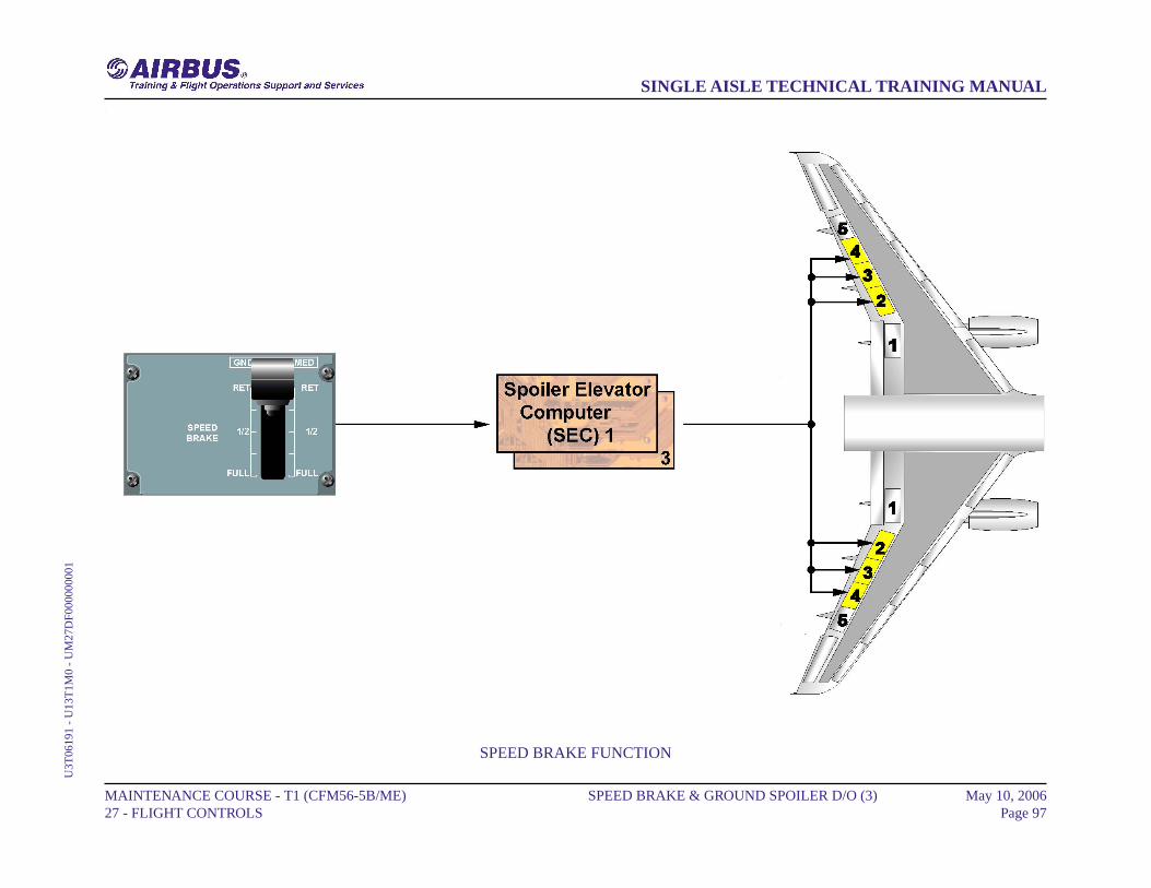
The speed brake function is commanded in the flight phase following apilot's action on the speed brake lever. The speed brakes can be drivenby Spoiler and Elevator Computers (SECs) 1 and 3, and supplied fromthe hydraulic system. The surfaces ensuring this function are spoilers 2thru 4. When one surface is not available on one wing, the symmetricalone, on the other wing, is inhibited. The switching to alternate or directlaws does not affect the speed brake function.The different priorities of this function are:- the roll order has priority over the speed brake function. When the sumof roll and speed brake commands, relative to one surface, is greater thanthe maximum possible deflection, the symmetrical surface is retracteduntil the difference between the two surfaces is equal to the roll order,- if the Angle-Of-Attack (AOA) protection is activated with speed brakesextended, the speed brakes are automatically retracted.
MAINTENANCE COURSE - T1 (CFM56-5B/ME) 27 - FLIGHT CONTROLS
SPEED BRAKE & GROUND SPOILER D/O (3) May 10, 2006Page 96
SINGLE AISLE TECHNICAL TRAINING MANUALU
3T06
191
- U
13T
1M0
- U
M27
DF0
0000
0001
SPEED BRAKE FUNCTION
MAINTENANCE COURSE - T1 (CFM56-5B/ME) 27 - FLIGHT CONTROLS
SPEED BRAKE & GROUND SPOILER D/O (3) May 10, 2006Page 97
SINGLE AISLE TECHNICAL TRAINING MANUALU
3T06
191
- U
13T
1M0
- U
M27
DF0
0000
0001
SPEED BRAKE & GROUND SPOILER D/O (3)
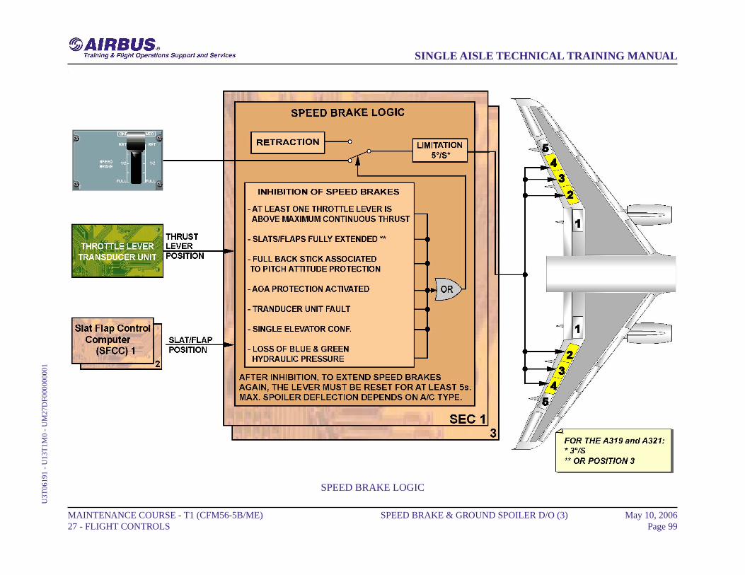
SPEED BRAKE LOGIC
The speed brake control lever gives the command of the speed brake.The SECs receive the information from the Slats and Flaps ControlComputers (SFCCs) and the throttle lever transducer unit. Speed brakeextension is inhibited in following cases:- SEC 1 and 3 fault,- elevator left or right (in this case only spoiler 3 & 4 are inhibited),- Angle-Of-Attack (AOA) protection is active,- in FLAP FULL configuration (A319/320) or FLAPS 3 position (A321).If speed brakes are extended, they automatically retract and kept retracteduntil inhibition condition disappears and lever reset.
MAINTENANCE COURSE - T1 (CFM56-5B/ME) 27 - FLIGHT CONTROLS
SPEED BRAKE & GROUND SPOILER D/O (3) May 10, 2006Page 98
SINGLE AISLE TECHNICAL TRAINING MANUALU
3T06
191
- U
13T
1M0
- U
M27
DF0
0000
0001
SPEED BRAKE LOGIC
MAINTENANCE COURSE - T1 (CFM56-5B/ME) 27 - FLIGHT CONTROLS
SPEED BRAKE & GROUND SPOILER D/O (3) May 10, 2006Page 99
SINGLE AISLE TECHNICAL TRAINING MANUALU
3T06
191
- U
13T
1M0
- U
M27
DF0
0000
0001

SPEED BRAKE & GROUND SPOILER D/O (3)
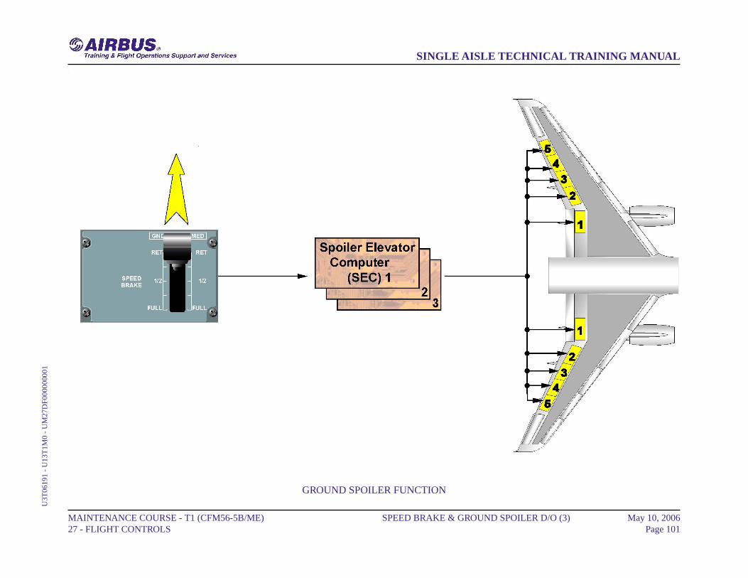
GROUND SPOILER FUNCTION
When the logic conditions, which determine the lift dumper extension,are fulfilled, a deflection order is sent to spoilers 1 to 5, to 10º or 50ºextension depending on the state of both Main Landing Gear (MLG) legs,compressed or not. Ground spoilers are armed when the speed brakecontrol lever is pulled up, in manual mode. Moreover, a pitchpre-command at ground spoiler extension/retraction avoids induced pitcheffects, in normal or AP mode. The ground spoiler function is automatic.
MAINTENANCE COURSE - T1 (CFM56-5B/ME) 27 - FLIGHT CONTROLS
SPEED BRAKE & GROUND SPOILER D/O (3) May 10, 2006Page 100
SINGLE AISLE TECHNICAL TRAINING MANUALU
3T06
191
- U
13T
1M0
- U
M27
DF0
0000
0001
GROUND SPOILER FUNCTION
MAINTENANCE COURSE - T1 (CFM56-5B/ME) 27 - FLIGHT CONTROLS
SPEED BRAKE & GROUND SPOILER D/O (3) May 10, 2006Page 101
SINGLE AISLE TECHNICAL TRAINING MANUALU
3T06
191
- U
13T
1M0
- U
M27
DF0
0000
0001
SPEED BRAKE & GROUND SPOILER D/O (3)
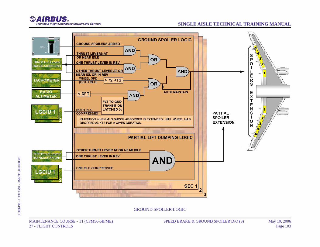
GROUND SPOILER LOGIC
The ground spoiler control is entirely automatic. Achieved by the spoilers1 to 5. The maximum deflection is 50° with a deflection rate of30°/second.The ground spoilers are armed:- when the speed brake control lever is pulled up into the ARMEDposition.Ground spoilers automatically extend when armed:- both thrust levers at forward idle and both MLG touch down (Flight /Ground transition),- or during Take Off (TO) run at speed greater than 72 knots (kts) andboth thrust levers retarded at forward idle.Ground spoilers automatically extended (not armed):- when both MLG touch down and reverse is selected on at least oneengine (remaining engine at idle),- or during TO run speed greater than 72 kts and reverse is selected onat least one engine (remaining engine at idle).Ground spoilers partially extend:- when reverse is selected on at least one engine (remaining engine atidle) and one MLG is compressed.This partial extension (10°), by decreasing the lift, will ease thecompression of the second MLG, and consequently will lead to the normalground spoiler extension.
NOTE: Note: The speed brake handle will not move during spoilerdeflection or retraction. The spoiler position will be displayedon the lower ECAM display WHEEL page.
MAINTENANCE COURSE - T1 (CFM56-5B/ME) 27 - FLIGHT CONTROLS
SPEED BRAKE & GROUND SPOILER D/O (3) May 10, 2006Page 102
SINGLE AISLE TECHNICAL TRAINING MANUALU
3T06
191
- U
13T
1M0
- U
M27
DF0
0000
0001
GROUND SPOILER LOGIC
MAINTENANCE COURSE - T1 (CFM56-5B/ME) 27 - FLIGHT CONTROLS
SPEED BRAKE & GROUND SPOILER D/O (3) May 10, 2006Page 103
SINGLE AISLE TECHNICAL TRAINING MANUALU
3T06
191
- U
13T
1M0
- U
M27
DF0
0000
0001

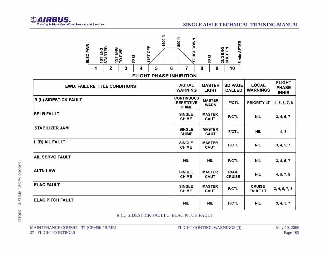
FLIGHT CONTROL WARNINGS (3)
R (L) SIDESTICK FAULT
In case of side stick configuration warning the aural warning sounds, theMASTER WARNing and the SIDESTICK PRIORITY come on. Thefailure is shown red on the EWD.
SPLR FAULT
In case of a faulty pair of spoilers the aural warning sounds and theMASTER CAUTion comes on. The failure is shown amber on the EWDrelated to the indications on the F/CTL ECAM page.
STABILIZER JAM
In case of stabilizer jam the aural warning sounds and the MASTERCAUT comes on. The failure is shown amber on the EWD related to theindications on the F/CTL ECAM page.
L (R) AIL FAULT
In case of dual aileron servo fault the aural warning sounds and theMASTER CAUT comes on. The failure is shown amber on the EWDrelated to the indications on the F/CTL ECAM page.
AIL SERVO FAULT
In case of aileron servo fault, the failure is shown amber on the EWDrelated to the indications on the F/CTL ECAM page.
ALTN LAW
In case of F/CTL normal law failure the aural warning sounds and theMASTER CAUT comes on. The F/CTL ECAM page is not called.
ELAC FAULT
In case of Flight Control Computer (FCC) failure the aural warningsounds, the MASTER CAUT and the related P/BSW FAULT light comeon. The failure is shown amber on the EWD related to the indications onthe F/CTL ECAM page.
ELAC PITCH FAULT
In case of ELAC pitch fault the ECAM is activated. The failure is shownamber on the EWD. The ELAC symbol remains green.
MAINTENANCE COURSE - T1 (CFM56-5B/ME) 27 - FLIGHT CONTROLS
FLIGHT CONTROL WARNINGS (3) May 10, 2006Page 104
SINGLE AISLE TECHNICAL TRAINING MANUALU
3T06
191
- U
13T
1M0
- U
M27
W10
0000
0001
R (L) SIDESTICK FAULT ... ELAC PITCH FAULT
MAINTENANCE COURSE - T1 (CFM56-5B/ME) 27 - FLIGHT CONTROLS
FLIGHT CONTROL WARNINGS (3) May 10, 2006Page 105
SINGLE AISLE TECHNICAL TRAINING MANUALU
3T06
191
- U
13T
1M0
- U
M27
W10
0000
0001

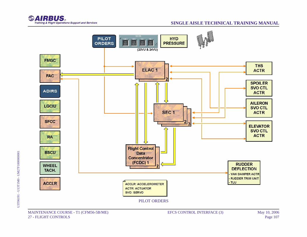
EFCS CONTROL INTERFACE (3)
PILOT ORDERS
The pilot orders like side stick, speed brake, ground spoiler or throttleposition signals, are transmitted to the ELevator Aileron Computers(ELACs) and Spoiler Elevator Computers (SECs). According to theseinputs and their control laws, the computers calculate the elevator, aileron,spoiler, THS and rudder deflection.
MAINTENANCE COURSE - T1 (CFM56-5B/ME) 27 - FLIGHT CONTROLS
EFCS CONTROL INTERFACE (3) May 10, 2006Page 106
SINGLE AISLE TECHNICAL TRAINING MANUALU
3T06
191
- U
13T
1M0
- U
M27
F100
0000
001
PILOT ORDERS
MAINTENANCE COURSE - T1 (CFM56-5B/ME) 27 - FLIGHT CONTROLS
EFCS CONTROL INTERFACE (3) May 10, 2006Page 107
SINGLE AISLE TECHNICAL TRAINING MANUALU
3T06
191
- U
13T
1M0
- U
M27
F100
0000
001

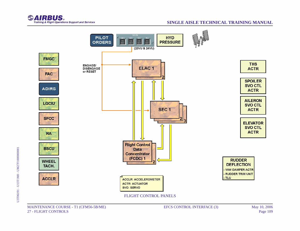
EFCS CONTROL INTERFACE (3)
FLIGHT CONTROL PANELS
P/Bs located on the FLighT ConTroL panels are used to engage/disengageor reset their respective computer software.
MAINTENANCE COURSE - T1 (CFM56-5B/ME) 27 - FLIGHT CONTROLS
EFCS CONTROL INTERFACE (3) May 10, 2006Page 108
SINGLE AISLE TECHNICAL TRAINING MANUALU
3T06
191
- U
13T
1M0
- U
M27
F100
0000
001
FLIGHT CONTROL PANELS
MAINTENANCE COURSE - T1 (CFM56-5B/ME) 27 - FLIGHT CONTROLS
EFCS CONTROL INTERFACE (3) May 10, 2006Page 109
SINGLE AISLE TECHNICAL TRAINING MANUALU
3T06
191
- U
13T
1M0
- U
M27
F100
0000
001
EFCS CONTROL INTERFACE (3)
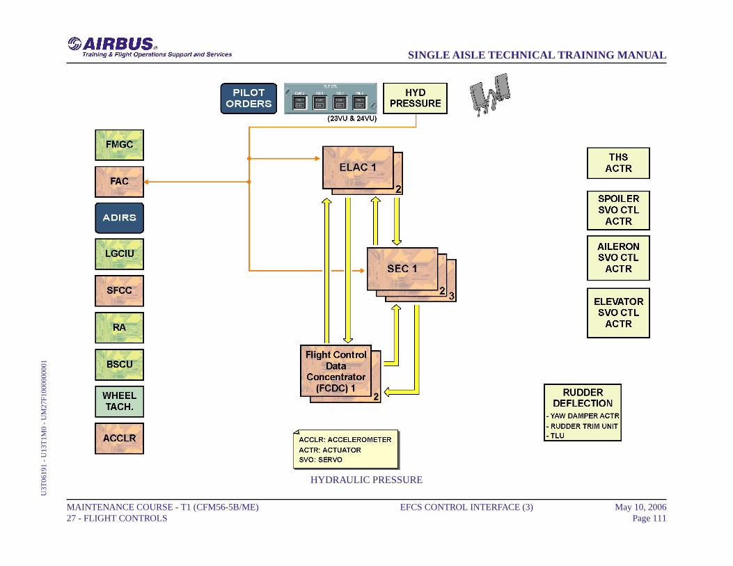
HYDRAULIC PRESSURE
The hydraulic pressure status is sent to the ELACs and SECs for activationor deactivation of the related servo controls and laws. The hydraulicpressure is also sent to the Flight Augmentation Computers (FACs), atleast for yellow and green for the yaw damper actuator.
MAINTENANCE COURSE - T1 (CFM56-5B/ME) 27 - FLIGHT CONTROLS
EFCS CONTROL INTERFACE (3) May 10, 2006Page 110
SINGLE AISLE TECHNICAL TRAINING MANUALU
3T06
191
- U
13T
1M0
- U
M27
F100
0000
001
HYDRAULIC PRESSURE
MAINTENANCE COURSE - T1 (CFM56-5B/ME) 27 - FLIGHT CONTROLS
EFCS CONTROL INTERFACE (3) May 10, 2006Page 111
SINGLE AISLE TECHNICAL TRAINING MANUALU
3T06
191
- U
13T
1M0
- U
M27
F100
0000
001

EFCS CONTROL INTERFACE (3)
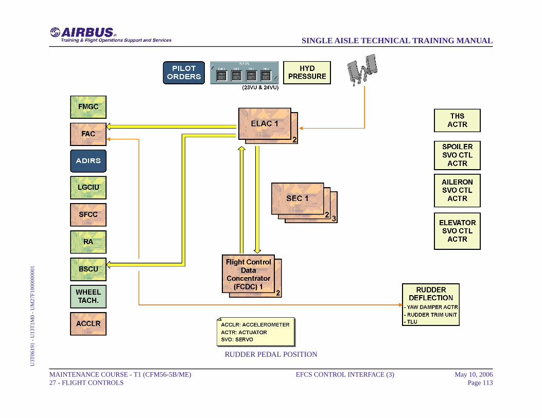
RUDDER PEDAL POSITION
The signal from the rudder pedal transducers is used for nose wheelsteering via ELACs / Braking Steering Control Unit (BSCU) and to tellELACs / FACs that the pilot is now in control for turn coordination, whileyaw damping signals are maintained.
MAINTENANCE COURSE - T1 (CFM56-5B/ME) 27 - FLIGHT CONTROLS
EFCS CONTROL INTERFACE (3) May 10, 2006Page 112
SINGLE AISLE TECHNICAL TRAINING MANUALU
3T06
191
- U
13T
1M0
- U
M27
F100
0000
001
RUDDER PEDAL POSITION
MAINTENANCE COURSE - T1 (CFM56-5B/ME) 27 - FLIGHT CONTROLS
EFCS CONTROL INTERFACE (3) May 10, 2006Page 113
SINGLE AISLE TECHNICAL TRAINING MANUALU
3T06
191
- U
13T
1M0
- U
M27
F100
0000
001
EFCS CONTROL INTERFACE (3)
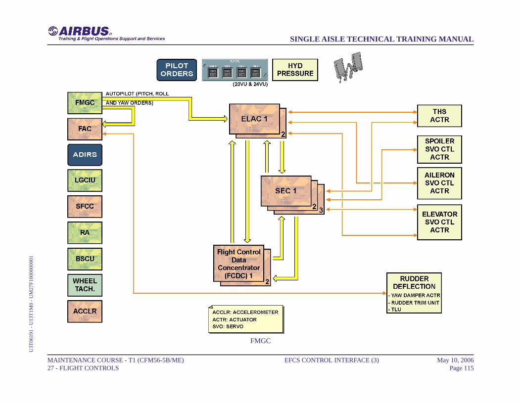
FMGC
If the autopilot is active, pitch, roll and yaw orders computed by the FlightManagement and Guidance Computer (FMGC) are sent to the ELACsand FACs, which control and monitor the surface deflections.
MAINTENANCE COURSE - T1 (CFM56-5B/ME) 27 - FLIGHT CONTROLS
EFCS CONTROL INTERFACE (3) May 10, 2006Page 114
SINGLE AISLE TECHNICAL TRAINING MANUALU
3T06
191
- U
13T
1M0
- U
M27
F100
0000
001
FMGC
MAINTENANCE COURSE - T1 (CFM56-5B/ME) 27 - FLIGHT CONTROLS
EFCS CONTROL INTERFACE (3) May 10, 2006Page 115
SINGLE AISLE TECHNICAL TRAINING MANUALU
3T06
191
- U
13T
1M0
- U
M27
F100
0000
001

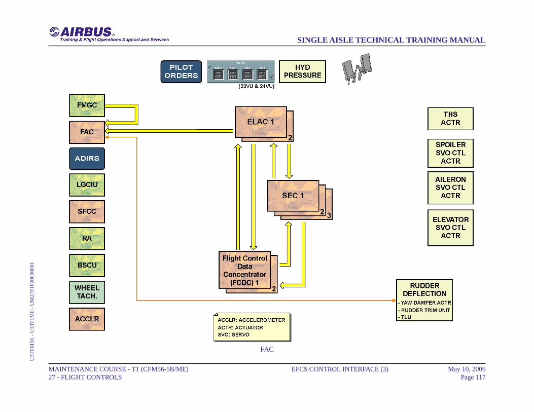
EFCS CONTROL INTERFACE (3)
FAC
The FACs receive rudder deflection information computed either by theELACs or FMGCs for dutch roll damping, engine failure compensationand turn coordination.
MAINTENANCE COURSE - T1 (CFM56-5B/ME) 27 - FLIGHT CONTROLS
EFCS CONTROL INTERFACE (3) May 10, 2006Page 116
SINGLE AISLE TECHNICAL TRAINING MANUALU
3T06
191
- U
13T
1M0
- U
M27
F100
0000
001
FAC
MAINTENANCE COURSE - T1 (CFM56-5B/ME) 27 - FLIGHT CONTROLS
EFCS CONTROL INTERFACE (3) May 10, 2006Page 117
SINGLE AISLE TECHNICAL TRAINING MANUALU
3T06
191
- U
13T
1M0
- U
M27
F100
0000
001
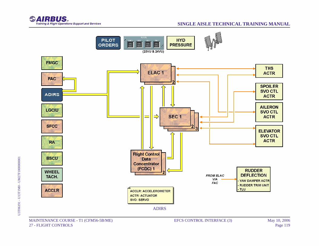
EFCS CONTROL INTERFACE (3)
ADIRS
The Air Data/Inertial Reference System (ADIRS) transmits air data andinertial reference data to the ELACs and SECs, and also to the FACs (seeATA 22 course) for flight envelope protection computation.
MAINTENANCE COURSE - T1 (CFM56-5B/ME) 27 - FLIGHT CONTROLS
EFCS CONTROL INTERFACE (3) May 10, 2006Page 118
SINGLE AISLE TECHNICAL TRAINING MANUALU
3T06
191
- U
13T
1M0
- U
M27
F100
0000
001
ADIRS
MAINTENANCE COURSE - T1 (CFM56-5B/ME) 27 - FLIGHT CONTROLS
EFCS CONTROL INTERFACE (3) May 10, 2006Page 119
SINGLE AISLE TECHNICAL TRAINING MANUALU
3T06
191
- U
13T
1M0
- U
M27
F100
0000
001

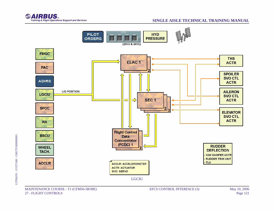
EFCS CONTROL INTERFACE (3)
LGCIU
The Landing Gear Control and Interface Units (LGCIUs) transmit L/Gposition information to the ELACs and SECs.
MAINTENANCE COURSE - T1 (CFM56-5B/ME) 27 - FLIGHT CONTROLS
EFCS CONTROL INTERFACE (3) May 10, 2006Page 120
SINGLE AISLE TECHNICAL TRAINING MANUALU
3T06
191
- U
13T
1M0
- U
M27
F100
0000
001
LGCIU
MAINTENANCE COURSE - T1 (CFM56-5B/ME) 27 - FLIGHT CONTROLS
EFCS CONTROL INTERFACE (3) May 10, 2006Page 121
SINGLE AISLE TECHNICAL TRAINING MANUALU
3T06
191
- U
13T
1M0
- U
M27
F100
0000
001
EFCS CONTROL INTERFACE (3)
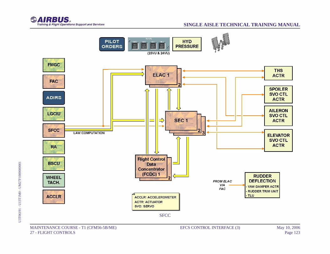
SFCC
The Slat Flap Control Computers (SFCCs) transmit slat flap surfaceposition to the ELACs and SECs for law computation.
MAINTENANCE COURSE - T1 (CFM56-5B/ME) 27 - FLIGHT CONTROLS
EFCS CONTROL INTERFACE (3) May 10, 2006Page 122
SINGLE AISLE TECHNICAL TRAINING MANUALU
3T06
191
- U
13T
1M0
- U
M27
F100
0000
001
SFCC
MAINTENANCE COURSE - T1 (CFM56-5B/ME) 27 - FLIGHT CONTROLS
EFCS CONTROL INTERFACE (3) May 10, 2006Page 123
SINGLE AISLE TECHNICAL TRAINING MANUALU
3T06
191
- U
13T
1M0
- U
M27
F100
0000
001

EFCS CONTROL INTERFACE (3)
RA
The Radio Altimeter (RA) transmits the altitude information to the ELACsfor flare law activation.
MAINTENANCE COURSE - T1 (CFM56-5B/ME) 27 - FLIGHT CONTROLS
EFCS CONTROL INTERFACE (3) May 10, 2006Page 124
SINGLE AISLE TECHNICAL TRAINING MANUALU
3T06
191
- U
13T
1M0
- U
M27
F100
0000
001

RA
MAINTENANCE COURSE - T1 (CFM56-5B/ME) 27 - FLIGHT CONTROLS
EFCS CONTROL INTERFACE (3) May 10, 2006Page 125
SINGLE AISLE TECHNICAL TRAINING MANUALU
3T06
191
- U
13T
1M0
- U
M27
F100
0000
001
EFCS CONTROL INTERFACE (3)
BSCU
The BSCU receives information from the ELACs for the nose wheelsteering system and from the SECs for the auto brake function.
MAINTENANCE COURSE - T1 (CFM56-5B/ME) 27 - FLIGHT CONTROLS
EFCS CONTROL INTERFACE (3) May 10, 2006Page 126
SINGLE AISLE TECHNICAL TRAINING MANUALU
3T06
191
- U
13T
1M0
- U
M27
F100
0000
001
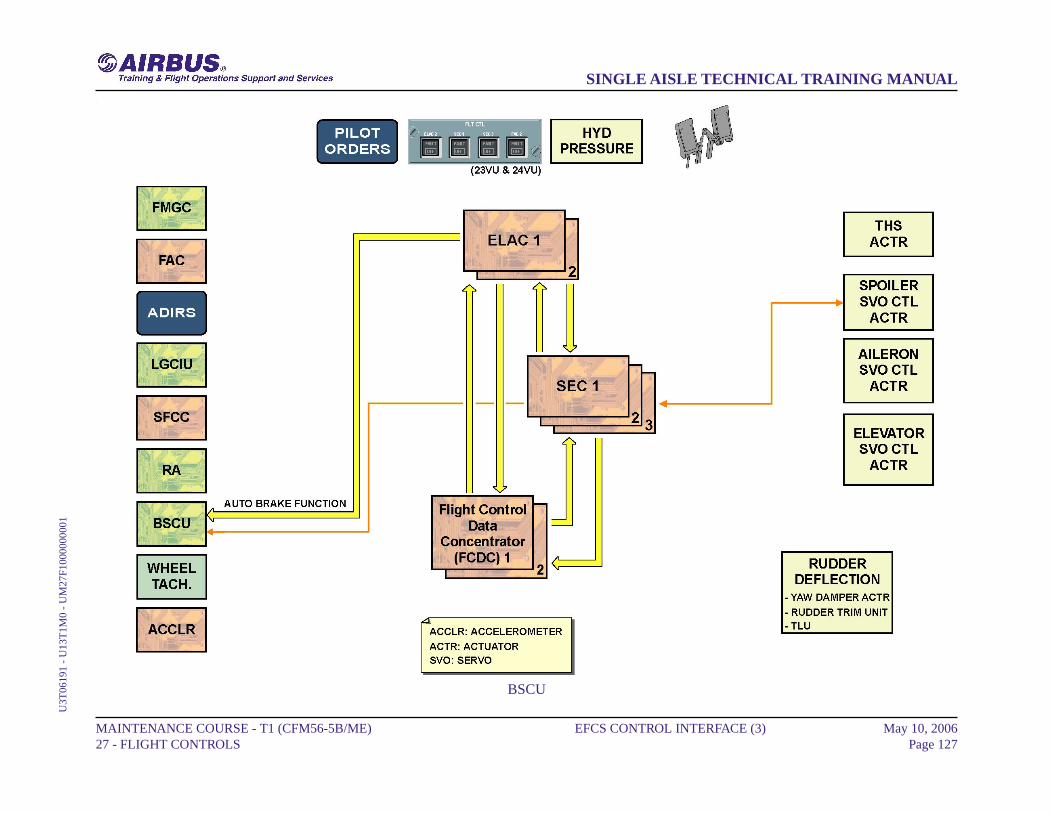
BSCU
MAINTENANCE COURSE - T1 (CFM56-5B/ME) 27 - FLIGHT CONTROLS
EFCS CONTROL INTERFACE (3) May 10, 2006Page 127
SINGLE AISLE TECHNICAL TRAINING MANUALU
3T06
191
- U
13T
1M0
- U
M27
F100
0000
001
EFCS CONTROL INTERFACE (3)
WHEEL TACHOMETER
Each MLG wheel speed is transmitted by wheel tachometers to the SECsfor ground spoiler, only in case of Rejected Take-Off.
MAINTENANCE COURSE - T1 (CFM56-5B/ME) 27 - FLIGHT CONTROLS
EFCS CONTROL INTERFACE (3) May 10, 2006Page 128
SINGLE AISLE TECHNICAL TRAINING MANUALU
3T06
191
- U
13T
1M0
- U
M27
F100
0000
001
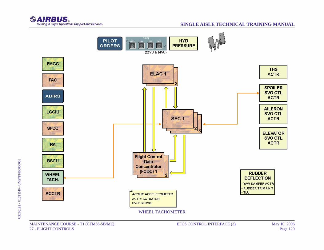
WHEEL TACHOMETER
MAINTENANCE COURSE - T1 (CFM56-5B/ME) 27 - FLIGHT CONTROLS
EFCS CONTROL INTERFACE (3) May 10, 2006Page 129
SINGLE AISLE TECHNICAL TRAINING MANUALU
3T06
191
- U
13T
1M0
- U
M27
F100
0000
001
EFCS CONTROL INTERFACE (3)
ACCELEROMETER
The vertical accelerometers, installed in the FWD cargo compartment,transmit the vertical acceleration of the A/C to the ELACs and SECs.The vertical accelerometers are also used for the computation of the pitchtrim function and load factor function.
MAINTENANCE COURSE - T1 (CFM56-5B/ME) 27 - FLIGHT CONTROLS
EFCS CONTROL INTERFACE (3) May 10, 2006Page 130
SINGLE AISLE TECHNICAL TRAINING MANUALU
3T06
191
- U
13T
1M0
- U
M27
F100
0000
001
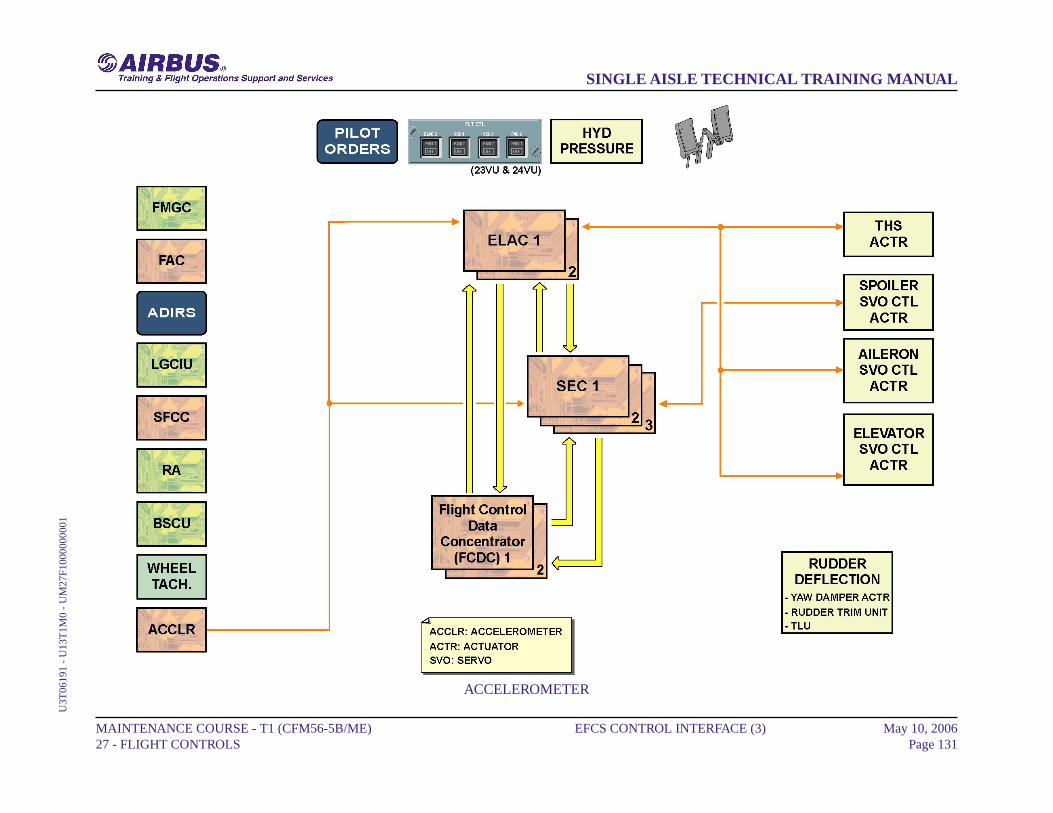
ACCELEROMETER
MAINTENANCE COURSE - T1 (CFM56-5B/ME) 27 - FLIGHT CONTROLS
EFCS CONTROL INTERFACE (3) May 10, 2006Page 131
SINGLE AISLE TECHNICAL TRAINING MANUALU
3T06
191
- U
13T
1M0
- U
M27
F100
0000
001
EFCS MONITOR INTERFACE (3)
FWC/ECAM
The flight control system failures are sent to the Flight WarningComputers (FWCs) by the Flight Control Data Concentrators (FCDCs).The FWCs elaborate the failure messages on the EWD display. The FWCsreceive flight control data from the FCDCs for indication on the ECAMdisplays.
CFDIU/MCDU
Data are exchanged between the FCDCs and the Centralized Fault DisplaySystem (CFDS), which enables two communication modes, normal modeand interactive mode.Normal mode:- the FCDCs send the flight control system failures to the CFDS,- the CFDS adds general data such as time, date, ATA chapter, flightphase, leg, to the failure message on the MCDU display.Interactive mode: the CFDS sends to the FCDCs:- the request for consultation of the BITE inside each computer,- the maintenance test request.The CFDS receives faulty Line Replaceable Unit (LRU) data from theFCDCs which are displayed on the MCDU for trouble-shooting and testpurposes.
MAINTENANCE COURSE - T1 (CFM56-5B/ME) 27 - FLIGHT CONTROLS
EFCS MONITOR INTERFACE (3) May 10, 2006Page 132
SINGLE AISLE TECHNICAL TRAINING MANUALU
3T06
191
- U
13T
1M0
- U
M27
F200
0000
001
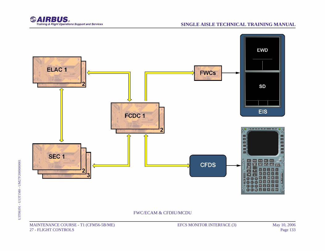
FWC/ECAM & CFDIU/MCDU
MAINTENANCE COURSE - T1 (CFM56-5B/ME) 27 - FLIGHT CONTROLS
EFCS MONITOR INTERFACE (3) May 10, 2006Page 133
SINGLE AISLE TECHNICAL TRAINING MANUALU
3T06
191
- U
13T
1M0
- U
M27
F200
0000
001
SLATS/FLAPS CONTROL D/O (3)
PCU/SFCC DESCRIPTION
This presentation shows the detailed operation of the Power Control Unit(PCU) and the Slat Flap Control Computer (SFCC), through a normalextension sequence. As slat and flap control is identical, only the flapsystem is shown. Each valve block includes three solenoid valves. Twoof them, called directional valves, command the control valve spool forretraction or extension, while the enable solenoid valve controls thePressure-Off Brake (POB).Moving the slat flap lever rotates the Command Sensor Unit (CSU),which issues a new position demand signal to each SFCC. This signal isprocessed in flap lanes 1 and 2. The position demand and the actualposition from the Feedback Position Pick-off Unit (FPPU) are comparedin the SFCC flap lanes. If the requested and actual positions are different,each lane generates command signals. The command signals generatedby each lane are compared. If the command signals are in agreement,drive commands are generated for PCU valve block activation. EachSFCC controls its related solenoid valve.
MAINTENANCE COURSE - T1 (CFM56-5B/ME) 27 - FLIGHT CONTROLS
SLATS/FLAPS CONTROL D/O (3) May 10, 2006Page 134
SINGLE AISLE TECHNICAL TRAINING MANUALU
3T06
191
- U
13T
1M0
- U
M27
DG
0000
0000
1
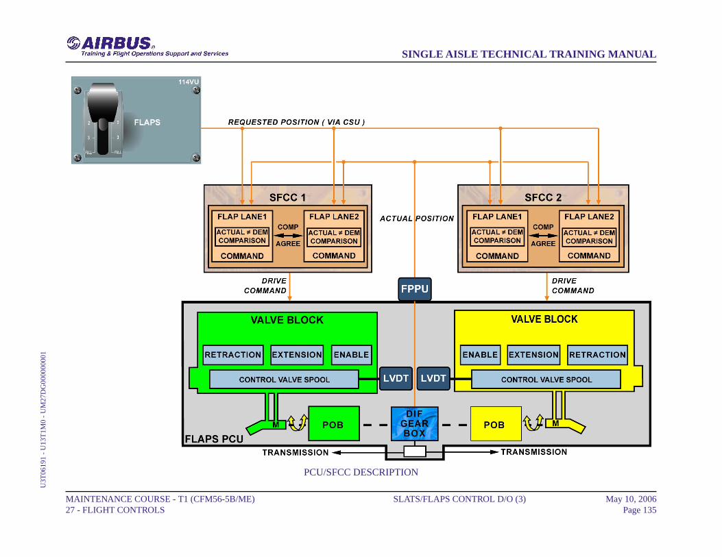
PCU/SFCC DESCRIPTION
MAINTENANCE COURSE - T1 (CFM56-5B/ME) 27 - FLIGHT CONTROLS
SLATS/FLAPS CONTROL D/O (3) May 10, 2006Page 135
SINGLE AISLE TECHNICAL TRAINING MANUALU
3T06
191
- U
13T
1M0
- U
M27
DG
0000
0000
1

SLATS/FLAPS CONTROL D/O (3)
SOLENOID VALVE
As the extend solenoid is energized, the control valve spool moves fromneutral towards the fully deflected position. The direction of valve spoolmovement controls the direction of rotation of the motor. The degree ofvalve spool movement controls the rotation speed of the motor.The position of the control valve spool is monitored by a Linear VariableDifferential Transducer (LVDT) mounted on one end of the valve block.The enable solenoid valve is energized to release the POB, and the flapsbegin to extend. With the control valve spool fully deflected, themaximum available fluid flow is directed to the motors which run at fullspeed for flap extension. As the flap approaches the requested position,the retract solenoid is energized permitting the control valve spool tomove back to the neutral position. The control valve spool movementreduces the fluid flow, which in turn reduces the motor speed.
MAINTENANCE COURSE - T1 (CFM56-5B/ME) 27 - FLIGHT CONTROLS
SLATS/FLAPS CONTROL D/O (3) May 10, 2006Page 136
SINGLE AISLE TECHNICAL TRAINING MANUALU
3T06
191
- U
13T
1M0
- U
M27
DG
0000
0000
1
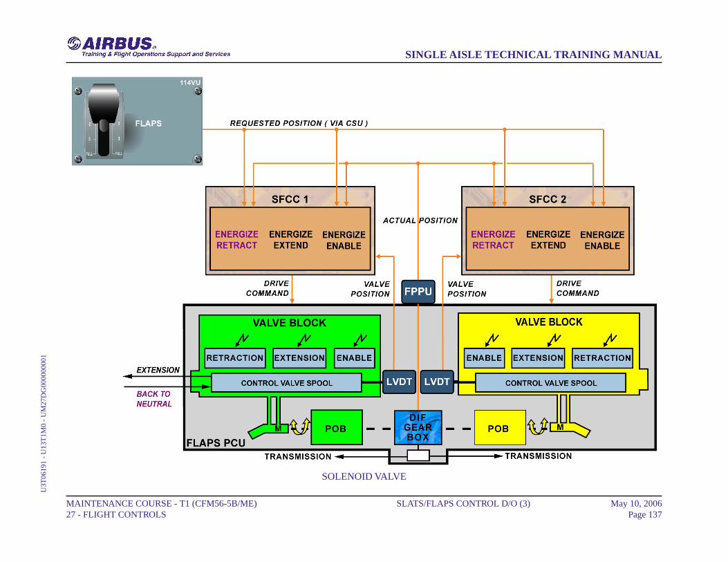
SOLENOID VALVE
MAINTENANCE COURSE - T1 (CFM56-5B/ME) 27 - FLIGHT CONTROLS
SLATS/FLAPS CONTROL D/O (3) May 10, 2006Page 137
SINGLE AISLE TECHNICAL TRAINING MANUALU
3T06
191
- U
13T
1M0
- U
M27
DG
0000
0000
1

SLATS/FLAPS CONTROL D/O (3)
POB
When the flaps reach the requested position, all solenoid valves arede-energized and the POB is applied. The motor stops and the POB isapplied to lock the flaps until a new position is requested.
MAINTENANCE COURSE - T1 (CFM56-5B/ME) 27 - FLIGHT CONTROLS
SLATS/FLAPS CONTROL D/O (3) May 10, 2006Page 138
SINGLE AISLE TECHNICAL TRAINING MANUALU
3T06
191
- U
13T
1M0
- U
M27
DG
0000
0000
1
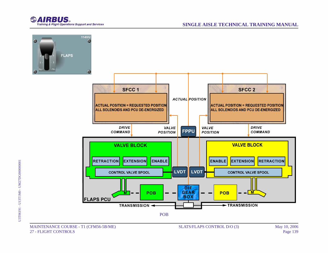
POB
MAINTENANCE COURSE - T1 (CFM56-5B/ME) 27 - FLIGHT CONTROLS
SLATS/FLAPS CONTROL D/O (3) May 10, 2006Page 139
SINGLE AISLE TECHNICAL TRAINING MANUALU
3T06
191
- U
13T
1M0
- U
M27
DG
0000
0000
1
SLATS/FLAPS ABNORMAL LOCKING OPERATION (3)
GENERAL
Here is a brief reminder of the Wing Tip Brake (WTB) application logic.Asymmetry, runaway, overspeed and uncommanded movement aredetected by cross comparison of Asymmetry Position Pick-Off Unit(APPU) and Feedback Position Pick-off Unit (FPPU) signals. If any ofthese failures are detected by a Slat Flap Control Computer (SFCC) andconfirmed by the second one, the WTBs are applied.
NOTE: Note that if an SFCC does not operate, the other SFCC receivesa WTB-arm signal automatically. Thus, if the second SFCCsubsequently detects a failure, a solenoid valve on each WTBis energized.
MAINTENANCE COURSE - T1 (CFM56-5B/ME) 27 - FLIGHT CONTROLS
SLATS/FLAPS ABNORMAL LOCKING OPERATION (3) May 10, 2006Page 140
SINGLE AISLE TECHNICAL TRAINING MANUALU
3T06
191
- U
13T
1M0
- U
M27
DL
0000
0000
1

GENERAL
MAINTENANCE COURSE - T1 (CFM56-5B/ME) 27 - FLIGHT CONTROLS
SLATS/FLAPS ABNORMAL LOCKING OPERATION (3) May 10, 2006Page 141
SINGLE AISLE TECHNICAL TRAINING MANUALU
3T06
191
- U
13T
1M0
- U
M27
DL
0000
0000
1

SLATS/FLAPS ABNORMAL LOCKING OPERATION (3)
ASYMMETRY
Asymmetry is defined as a positional difference between the LH and RHAPPUs. Asymmetry is usually due to a broken shaft between both APPUs.The asymmetry threshold is above 5° synchro positional differencebetween both APPUs.
RUNAWAYA runaway is given as a positional difference between both APPUsand the FPPU. Runaway on slats can occur when a component of thetorque shaft drive, common to the LH and RH wings breaks, leavingthe slat system free from the Power Control Unit (PCU) Pressure-OffBrake (POB). This results in air loads tending to retract the surfaces.Runaway on flaps can only be possible if the PCU gearbox is broken.Depending on the broken position, the air load tends to retract orextend the flaps.
OVERSPEEDAn overspeed is detected when the rotation speed of the torque shaftsmeasured by the Position Pickoff Unit (PPU) is too high.
MAINTENANCE COURSE - T1 (CFM56-5B/ME) 27 - FLIGHT CONTROLS
SLATS/FLAPS ABNORMAL LOCKING OPERATION (3) May 10, 2006Page 142
SINGLE AISLE TECHNICAL TRAINING MANUALU
3T06
191
- U
13T
1M0
- U
M27
DL
0000
0000
1

ASYMMETRY - RUNAWAY & OVERSPEED
MAINTENANCE COURSE - T1 (CFM56-5B/ME) 27 - FLIGHT CONTROLS
SLATS/FLAPS ABNORMAL LOCKING OPERATION (3) May 10, 2006Page 143
SINGLE AISLE TECHNICAL TRAINING MANUALU
3T06
191
- U
13T
1M0
- U
M27
DL
0000
0000
1
SLATS/FLAPS ABNORMAL LOCKING OPERATION (3)
UNCOMMANDED MOVEMENT
Uncommanded movement is defined as a movement away from theselected position by a value that exceeds the threshold.
MAINTENANCE COURSE - T1 (CFM56-5B/ME) 27 - FLIGHT CONTROLS
SLATS/FLAPS ABNORMAL LOCKING OPERATION (3) May 10, 2006Page 144
SINGLE AISLE TECHNICAL TRAINING MANUALU
3T06
191
- U
13T
1M0
- U
M27
DL
0000
0000
1
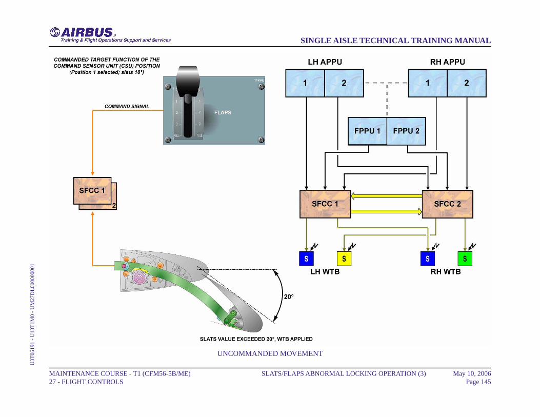
UNCOMMANDED MOVEMENT
MAINTENANCE COURSE - T1 (CFM56-5B/ME) 27 - FLIGHT CONTROLS
SLATS/FLAPS ABNORMAL LOCKING OPERATION (3) May 10, 2006Page 145
SINGLE AISLE TECHNICAL TRAINING MANUALU
3T06
191
- U
13T
1M0
- U
M27
DL
0000
0000
1
SLATS/FLAPS ABNORMAL LOCKING OPERATION (3)
FAILURE MONITORING
The PCU is in operation. The extended solenoid valve and the POBsolenoid valve are energized and the flaps extend. PPU information isused for system monitoring. Asymmetry is detected by SFCC1. Onceasymmetry has been detected by an SFCC, its associated valve block isde-energized. A "WTB arm" signal is sent to the SFCC2 flap channel tocheck whether asymmetry is confirmed or not. If the asymmetry isconfirmed by SFCC2, a "WTB arm" signal is sent to the WTB solenoids,PCUs are de-energized and the software is latched, a resetting is possibleon ground only via the Centralized Fault Display System (CFDS). Ifasymmetry is not confirmed by the second computer, the first system isconsidered faulty.
MAINTENANCE COURSE - T1 (CFM56-5B/ME) 27 - FLIGHT CONTROLS
SLATS/FLAPS ABNORMAL LOCKING OPERATION (3) May 10, 2006Page 146
SINGLE AISLE TECHNICAL TRAINING MANUALU
3T06
191
- U
13T
1M0
- U
M27
DL
0000
0000
1

FAILURE MONITORING
MAINTENANCE COURSE - T1 (CFM56-5B/ME) 27 - FLIGHT CONTROLS
SLATS/FLAPS ABNORMAL LOCKING OPERATION (3) May 10, 2006Page 147
SINGLE AISLE TECHNICAL TRAINING MANUALU
3T06
191
- U
13T
1M0
- U
M27
DL
0000
0000
1
SLATS/FLAPS ABNORMAL HALF SPEED OPERATION (3)
PRESENTATION
We will study examples of abnormal operations which cause the systemto operate at half speed. As slat and flap operations are identical, onlyflaps will be shown. When half speed is detected, a level 1 caution isgenerated and a fault message is displayed on the ECAM.
MAINTENANCE COURSE - T1 (CFM56-5B/ME) 27 - FLIGHT CONTROLS
SLATS/FLAPS ABNORMAL HALF SPEED OPERATION (3) May 10, 2006Page 148
SINGLE AISLE TECHNICAL TRAINING MANUALU
3T06
191
- U
13T
1M0
- U
M27
DM
0000
0000
1
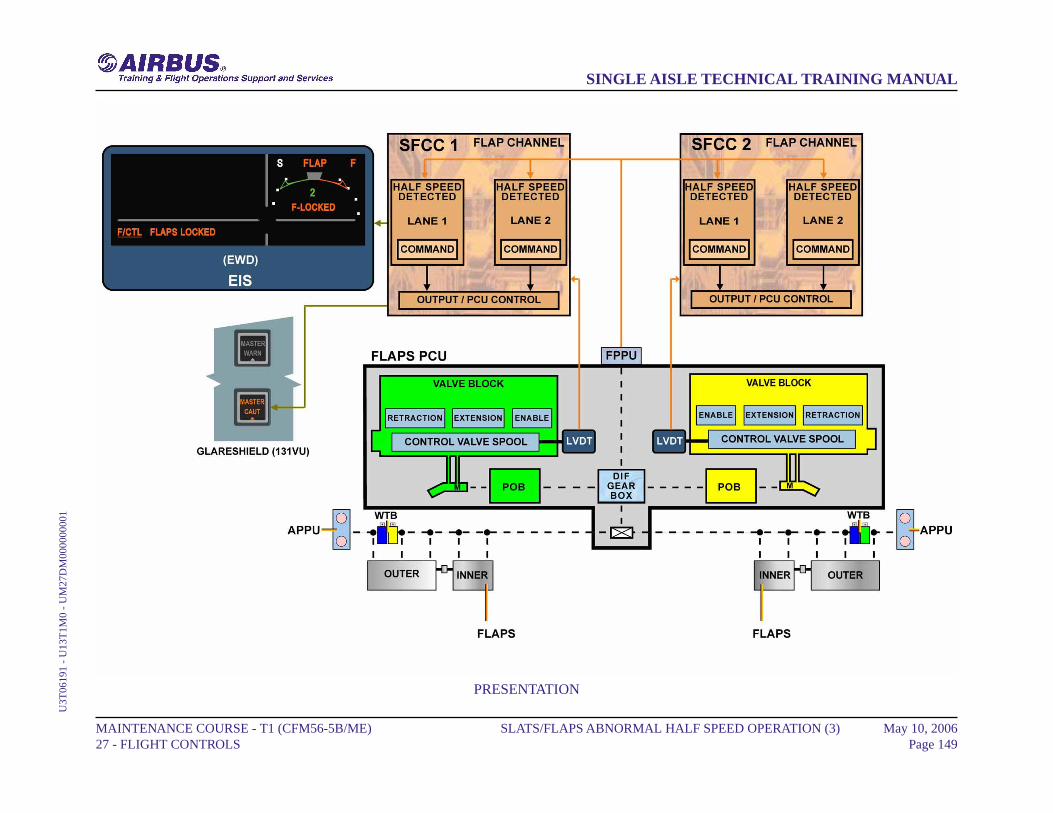
PRESENTATION
MAINTENANCE COURSE - T1 (CFM56-5B/ME) 27 - FLIGHT CONTROLS
SLATS/FLAPS ABNORMAL HALF SPEED OPERATION (3) May 10, 2006Page 149
SINGLE AISLE TECHNICAL TRAINING MANUALU
3T06
191
- U
13T
1M0
- U
M27
DM
0000
0000
1

SLATS/FLAPS ABNORMAL HALF SPEED OPERATION (3)
SFCC FAILURE
In this example Slat Flap Control Computer (SFCC) 2 flap channel isinoperative and SFCC 1 operates normally. Each flap channel lane ofSFCC 1 generates command signals. The drive commands, generated inthe Power Control Unit (PCU) input stage, control the related solenoidvalve in the flap PCU. Only the related green hydraulic motor is operative.As the yellow valve block is not energized, the Pressure-Off Brake (POB)holds the output shaft of the yellow hydraulic motor. Due to the reactionof one half of the differential gearbox, the operative motor supplies fulloutput torque at half speed.
MAINTENANCE COURSE - T1 (CFM56-5B/ME) 27 - FLIGHT CONTROLS
SLATS/FLAPS ABNORMAL HALF SPEED OPERATION (3) May 10, 2006Page 150
SINGLE AISLE TECHNICAL TRAINING MANUALU
3T06
191
- U
13T
1M0
- U
M27
DM
0000
0000
1
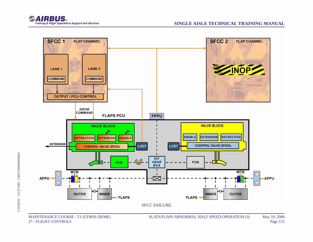
SFCC FAILURE
MAINTENANCE COURSE - T1 (CFM56-5B/ME) 27 - FLIGHT CONTROLS
SLATS/FLAPS ABNORMAL HALF SPEED OPERATION (3) May 10, 2006Page 151
SINGLE AISLE TECHNICAL TRAINING MANUALU
3T06
191
- U
13T
1M0
- U
M27
DM
0000
0000
1
SLATS/FLAPS ABNORMAL HALF SPEED OPERATION (3)
HYDRAULIC FAILURE
Each SFCC channel monitors the hydraulic pressure for its associatedPCU motor. Signals from the Linear Variable Differential Transducer(LVDT) are used to compare the position of the control valve with thedrive command orders. In this example, a green hydraulic low pressureis detected by SFCC1. As soon as the hydraulic pressure drop is detected,the PCU valve block solenoids are de-energized. The POB holds theoutput shaft of the green hydraulic motor. Only the yellow valve blockis energized, so only the yellow hydraulic motor is operative. Due to thereaction of one half of the differential gearbox, the operative yellow motorsupplies full output torque at half speed to the gearbox output shaft. Asthe green hydraulic system also supplies one slat PCU motor, the slatsystem is affected as well.
MAINTENANCE COURSE - T1 (CFM56-5B/ME) 27 - FLIGHT CONTROLS
SLATS/FLAPS ABNORMAL HALF SPEED OPERATION (3) May 10, 2006Page 152
SINGLE AISLE TECHNICAL TRAINING MANUALU
3T06
191
- U
13T
1M0
- U
M27
DM
0000
0000
1

HYDRAULIC FAILURE
MAINTENANCE COURSE - T1 (CFM56-5B/ME) 27 - FLIGHT CONTROLS
SLATS/FLAPS ABNORMAL HALF SPEED OPERATION (3) May 10, 2006Page 153
SINGLE AISLE TECHNICAL TRAINING MANUALU
3T06
191
- U
13T
1M0
- U
M27
DM
0000
0000
1
SLATS/FLAPS ABNORMAL HALF SPEED OPERATION (3)
SPOOL VALVE JAM
In this example, a green control spool valve jam causes a flap movementslower than the minimum speed for a two-motor operation. Each SFCCflap channel monitors the transmission system for half speed operation.Such a case can only be detected when both control spool valves areselected in full speed configuration with half speed monitoring. The halfspeed monitoring system detects the jammed spool valve and thus thesolenoid valves are de-energized. Due to the differential gearbox, theremaining operative motor provides full differential gearbox output torqueat half speed. Half speed monitoring is inhibited when the aircraft is onground.
MAINTENANCE COURSE - T1 (CFM56-5B/ME) 27 - FLIGHT CONTROLS
SLATS/FLAPS ABNORMAL HALF SPEED OPERATION (3) May 10, 2006Page 154
SINGLE AISLE TECHNICAL TRAINING MANUALU
3T06
191
- U
13T
1M0
- U
M27
DM
0000
0000
1

SPOOL VALVE JAM
MAINTENANCE COURSE - T1 (CFM56-5B/ME) 27 - FLIGHT CONTROLS
SLATS/FLAPS ABNORMAL HALF SPEED OPERATION (3) May 10, 2006Page 155
SINGLE AISLE TECHNICAL TRAINING MANUALU
3T06
191
- U
13T
1M0
- U
M27
DM
0000
0000
1
SLATS MECHANICAL DRIVE D/O (3)
GENERAL
Torque shafts and gearboxes transmit power from the Power ControlUnit (PCU) to the actuators which drive the slat operating mechanism.
PCUThe PCU incorporates two hydraulic motors, each controlled by anelectrically signaled valve block. The slat PCU drives the slattransmission system via a single output shaft.
TORQUE SHAFTSThe rotation of the torque shafts drives all gearboxes and rotaryactuator input shafts simultaneously and at the same speed. Steadybearings, attached to the structure, support the torque shafts wheresmall angular changes of alignment occur.
GEARBOXESSix gearboxes are used in the slat transmission system where changesin torque shaft alignment occur:- one 19-degree bevel gearbox changes alignment under the wingcenter box,- one T-gearbox changes alignment through 90 degrees in each wing,- two 63.5-degree bevel gearboxes take drive from below each winglevel into the wing leading edge.
ACTUATORSThe actuators produce the torque and speed reduction necessary todrive the slats at the required rate. Each actuator drives its associatedslat track through a pinion driven by the actuator output shaft.
MAINTENANCE COURSE - T1 (CFM56-5B/ME) 27 - FLIGHT CONTROLS
SLATS MECHANICAL DRIVE D/O (3) May 10, 2006Page 156
SINGLE AISLE TECHNICAL TRAINING MANUALU
3T06
191
- U
13T
1M0
- U
M27
DH
0000
0000
1
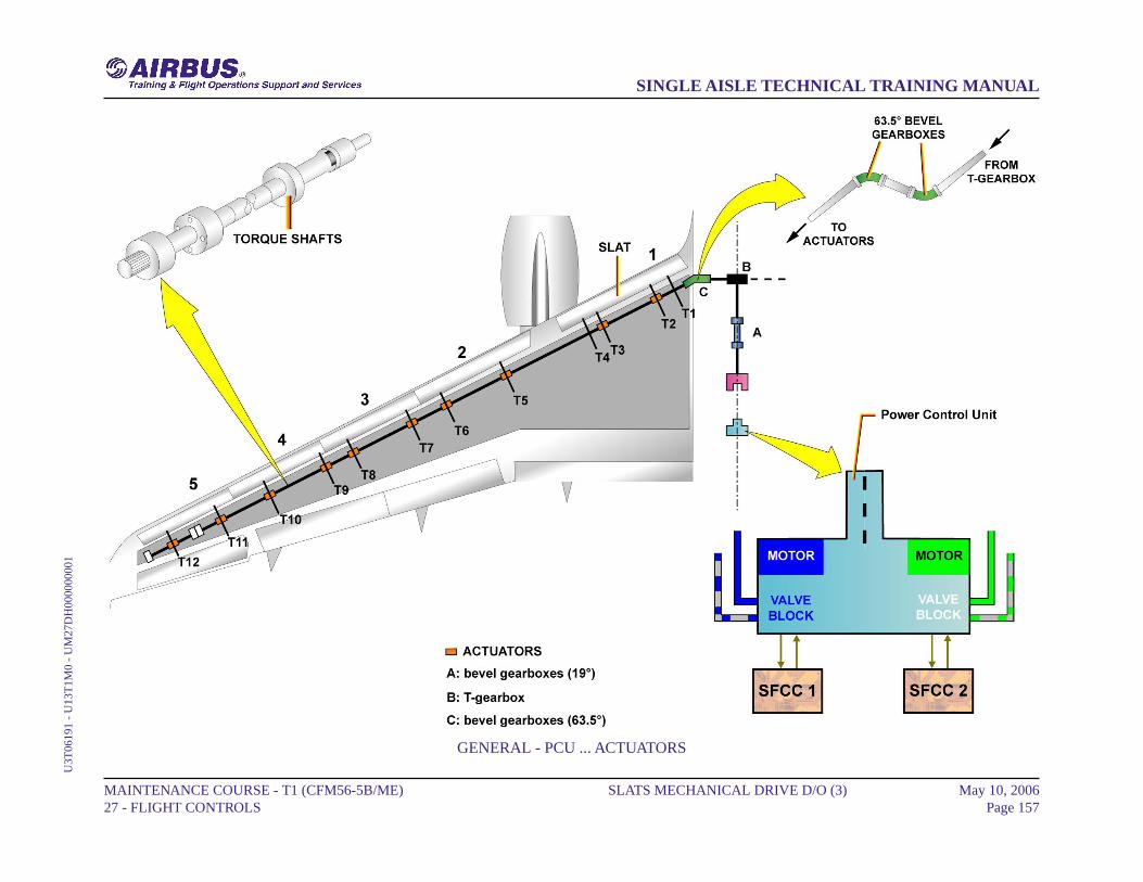
GENERAL - PCU ... ACTUATORS
MAINTENANCE COURSE - T1 (CFM56-5B/ME) 27 - FLIGHT CONTROLS
SLATS MECHANICAL DRIVE D/O (3) May 10, 2006Page 157
SINGLE AISLE TECHNICAL TRAINING MANUALU
3T06
191
- U
13T
1M0
- U
M27
DH
0000
0000
1
SLATS MECHANICAL DRIVE D/O (3)
TRACKS
The slats are attached to the forward ends of the tracks which run in guiderollers. Slat 1 is supported by four tracks, but only T2 and T3 are driven.T1 and T4 prevent slat loss in case of attachment failure. Slats outboardof the pylon are supported by two driven tracks.
TORQUE LIMITERSEach actuator incorporates a bi-directional torque limiter whichprotects the structure from overload.
WTBThe Wing Tip Brakes (WTBs) stop and hold the transmission if theSlat Flap Control Computers (SFCCs) detect abnormal operation suchas asymmetry and runaway. Once applied, the WTBs can only bereset on the ground by maintenance action via the Centralized FaultDisplay System (CFDS).
APPUThe Asymmetry Position Pick Off Units (APPUs) enable the SFCCto monitor the system for asymmetry and runaway conditions. OneAPPU is mounted outboard of track 12 in each wing. It gives the slatactual position to the SFCC.
MAINTENANCE COURSE - T1 (CFM56-5B/ME) 27 - FLIGHT CONTROLS
SLATS MECHANICAL DRIVE D/O (3) May 10, 2006Page 158
SINGLE AISLE TECHNICAL TRAINING MANUALU
3T06
191
- U
13T
1M0
- U
M27
DH
0000
0000
1
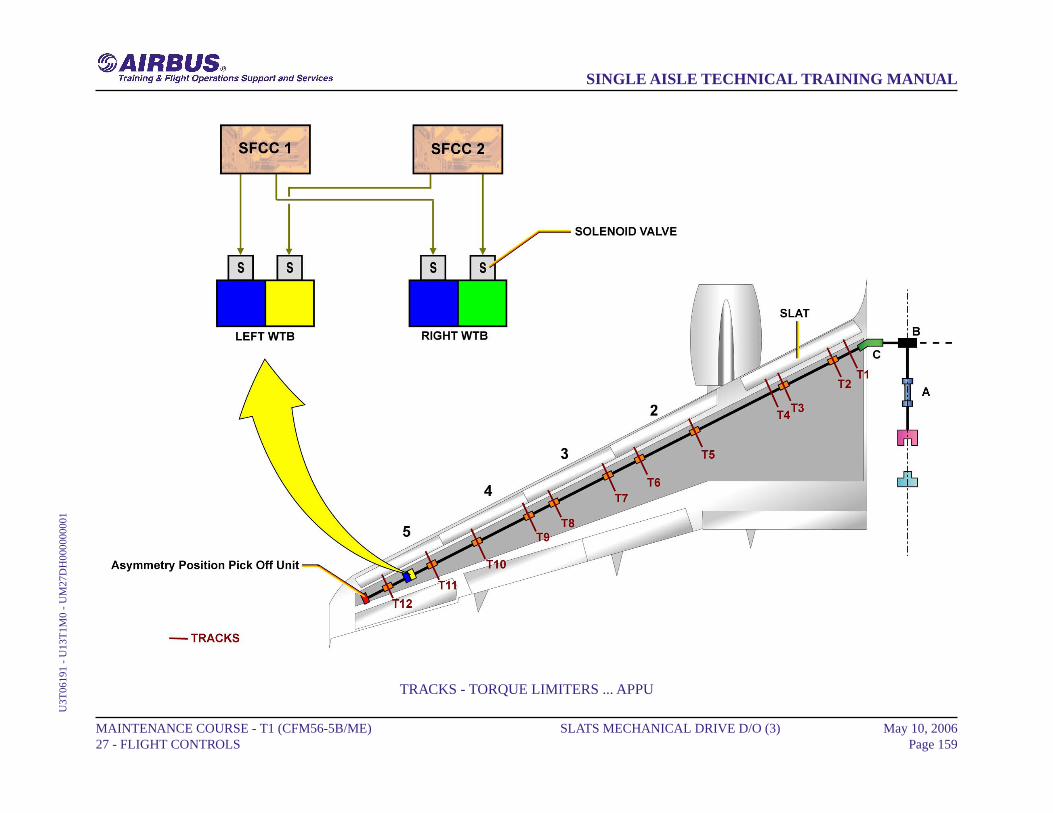
TRACKS - TORQUE LIMITERS ... APPU
MAINTENANCE COURSE - T1 (CFM56-5B/ME) 27 - FLIGHT CONTROLS
SLATS MECHANICAL DRIVE D/O (3) May 10, 2006Page 159
SINGLE AISLE TECHNICAL TRAINING MANUALU
3T06
191
- U
13T
1M0
- U
M27
DH
0000
0000
1
FLAPS MECHANICAL DRIVE D/O (3)
PCU
The Power Control Unit (PCU) incorporates two hydraulic motors, eachone controlled by an electrically-signaled valve block. The flap PCUdrives the flap transmission output shafts.
TORQUE SHAFTSThe rotation of the torque shafts drives all gearboxes and rotaryactuator input shafts simultaneously, at the same speed. Steadybearings, attached to the structure, support the torque shafts wheresmall angular changes are present.
GEARBOXESThree types of one-to-one ratio gearboxes are used in the flaptransmission where large changes in torque shaft alignment are present.A right angle gearbox changes alignment through 90 degrees for inputto track 1 offset gearbox. A line gearbox transmits the drive along therear face of the rear false spar. A 19-degree bevel gearbox aligns thedrive with the rear spar.
ACTUATORSOne actuator operates the flap mechanism at each track. It suppliesthe torque and speed reduction necessary to drive the flap at therequired rate. Each actuator is driven by an offset gearbox thattransmits power from the torque shaft to the plug-in rotary actuator.
TORQUE LIMITERSEach actuator incorporates a bi-directional torque limiter whichprotects the structure from overload.
WTBThe Wing Tip Brakes (WTBs) stop and hold the transmission if theSlat Flap Control Computers (SFCCs) detect abnormal operation suchas asymmetry, runaway or overspeed. Once applied, the WTBs can
only be reset on the ground, by maintenance action via the CentralizedFault Display System (CFDS).
APPUThe Asymmetry Position Pick Off Units (APPUs) enable the SFCCto monitor the system for asymmetry and runaway conditions. OneAPPU is mounted on the offset gearbox at track 4 in each wing. Itgives the flap actual position to the SFCC.
MAINTENANCE COURSE - T1 (CFM56-5B/ME) 27 - FLIGHT CONTROLS
FLAPS MECHANICAL DRIVE D/O (3) May 10, 2006Page 160
SINGLE AISLE TECHNICAL TRAINING MANUALU
3T06
191
- U
13T
1M0
- U
M27
DI0
0000
0001

PCU - TORQUE SHAFTS ... APPU
MAINTENANCE COURSE - T1 (CFM56-5B/ME) 27 - FLIGHT CONTROLS
FLAPS MECHANICAL DRIVE D/O (3) May 10, 2006Page 161
SINGLE AISLE TECHNICAL TRAINING MANUALU
3T06
191
- U
13T
1M0
- U
M27
DI0
0000
0001
FLAPS MECHANICAL DRIVE D/O (3)
TRACKS
Flaps are supported on carriages traveling on straight tracks. A link arm,outboard of each track, transmits drive from the actuator to the flap.Tracks 2, 3 and 4 are similar. Track 1, attached to the fuselage, uses adifferent configuration.
MAINTENANCE COURSE - T1 (CFM56-5B/ME) 27 - FLIGHT CONTROLS
FLAPS MECHANICAL DRIVE D/O (3) May 10, 2006Page 162
SINGLE AISLE TECHNICAL TRAINING MANUALU
3T06
191
- U
13T
1M0
- U
M27
DI0
0000
0001
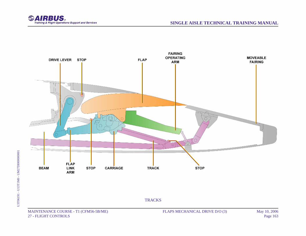
TRACKS
MAINTENANCE COURSE - T1 (CFM56-5B/ME) 27 - FLIGHT CONTROLS
FLAPS MECHANICAL DRIVE D/O (3) May 10, 2006Page 163
SINGLE AISLE TECHNICAL TRAINING MANUALU
3T06
191
- U
13T
1M0
- U
M27
DI0
0000
0001

FLAPS MECHANICAL DRIVE D/O (3) (A321)
PCU
The Power Control Unit (PCU) incorporates two hydraulic motors, eachone controlled by an electrically signaled valve block. The flap PCUdrives the flap transmission output shafts.
TORQUE SHAFTSThe rotation of the torque shafts drives all gearboxes and rotaryactuator input shafts simultaneously, at the same speed. Steadybearings, attached to the structure, support the torque shafts wheresmall angular changes are present.
GEARBOXESThree types of one-to-one ratio gearboxes are used in the flaptransmission where large changes in torque shaft alignment are present.A right angle gearbox changes alignment through 90 degrees for inputto track 1 offset gearbox. A line gearbox transmits the drive along therear face of the rear false spar. A 19-degree bevel gearbox aligns thedrive with the rear spar.
ACTUATORSOne actuator operates the flap mechanism at each track. It suppliesthe torque and speed reduction necessary to drive the flap at therequired rate. Each actuator is driven by an offset gearbox thattransmits power from the torque shaft to the plug-in rotary actuator.
TORQUE LIMITERSEach actuator incorporates a bi-directional torque limiter that protectsthe structure from overload.
WTBThe Wing Tip Brakes (WTBs) stop and hold the transmission if theSlat Flap Control Computers (SFCCs) detect abnormal operation suchas asymmetry, runaway or overspeed. Once applied, the WTBs can
only be reset on the ground, by maintenance action via the CentralizedFault Display System (CFDS).
APPUThe Asymmetry Position Pick Off Units (APPUs) enable the SFCCto monitor the system for asymmetry and runaway conditions. OneAPPU is mounted on the offset gearbox at track 4 in each wing. Itgives the flap actual position to the SFCC.
MAINTENANCE COURSE - T1 (CFM56-5B/ME) 27 - FLIGHT CONTROLS
FLAPS MECHANICAL DRIVE D/O (3) (A321) May 10, 2006Page 164
SINGLE AISLE TECHNICAL TRAINING MANUALU
3T06
191
- U
13T
1M0
- U
M27
DI0
0000
0002
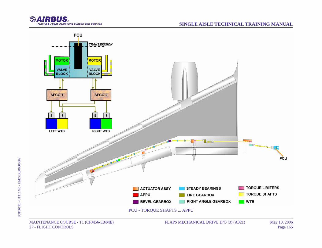
PCU - TORQUE SHAFTS ... APPU
MAINTENANCE COURSE - T1 (CFM56-5B/ME) 27 - FLIGHT CONTROLS
FLAPS MECHANICAL DRIVE D/O (3) (A321) May 10, 2006Page 165
SINGLE AISLE TECHNICAL TRAINING MANUALU
3T06
191
- U
13T
1M0
- U
M27
DI0
0000
0002

FLAPS MECHANICAL DRIVE D/O (3) (A321)
TRACKS
Flaps are supported on carriages traveling on straight tracks. A link arm,outboard of each track, transmits drive from the actuator to the flap.Tracks 2, 3 and 4 are similar. Track 1, attached to the fuselage, uses adifferent configuration.
MAINTENANCE COURSE - T1 (CFM56-5B/ME) 27 - FLIGHT CONTROLS
FLAPS MECHANICAL DRIVE D/O (3) (A321) May 10, 2006Page 166
SINGLE AISLE TECHNICAL TRAINING MANUALU
3T06
191
- U
13T
1M0
- U
M27
DI0
0000
0002
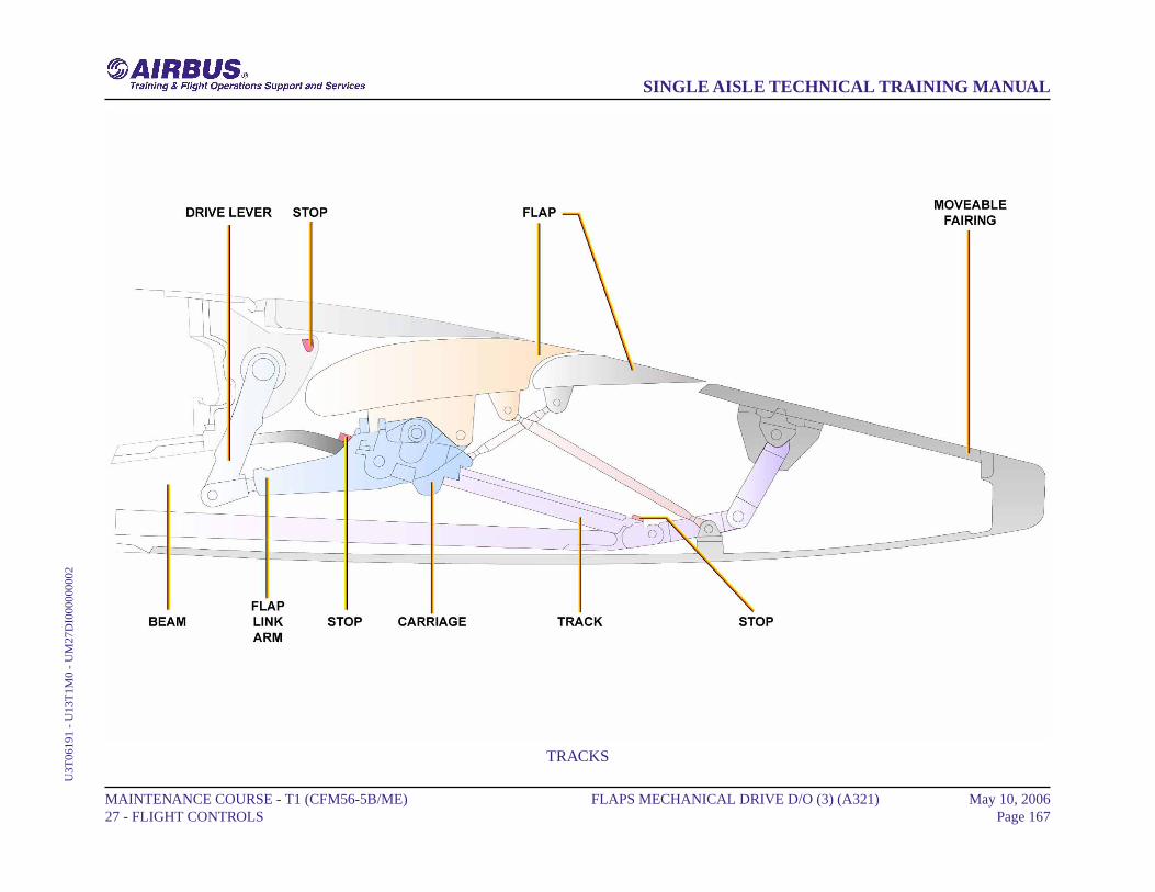
TRACKS
MAINTENANCE COURSE - T1 (CFM56-5B/ME) 27 - FLIGHT CONTROLS
FLAPS MECHANICAL DRIVE D/O (3) (A321) May 10, 2006Page 167
SINGLE AISLE TECHNICAL TRAINING MANUALU
3T06
191
- U
13T
1M0
- U
M27
DI0
0000
0002
FLAPS DRIVE STATIONS D/O (3)
GENERAL
Each flap is supported by carriages that run on tracks extending from thewing rear spar. Each carriage has a containment device to hold it on thetrack if a failure occurs. The carriages, tracks and beams at tracks 2, 3and 4 are of similar construction. Track 1 is attached to the fuselage.
MAINTENANCE COURSE - T1 (CFM56-5B/ME) 27 - FLIGHT CONTROLS
FLAPS DRIVE STATIONS D/O (3) May 10, 2006Page 168
SINGLE AISLE TECHNICAL TRAINING MANUALU
3T06
191
- U
13T
1M0
- U
M27
DK
0000
0000
1
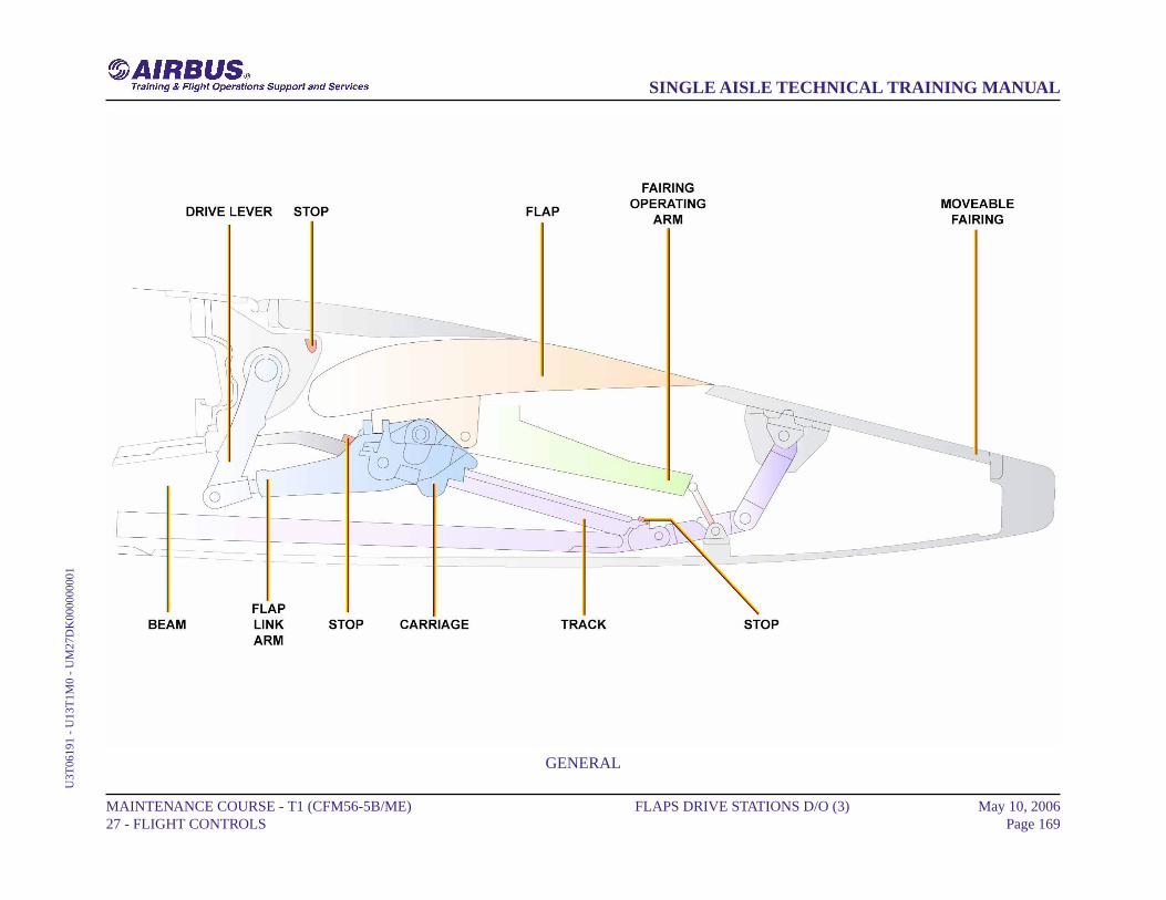
GENERAL
MAINTENANCE COURSE - T1 (CFM56-5B/ME) 27 - FLIGHT CONTROLS
FLAPS DRIVE STATIONS D/O (3) May 10, 2006Page 169
SINGLE AISLE TECHNICAL TRAINING MANUALU
3T06
191
- U
13T
1M0
- U
M27
DK
0000
0000
1
FLAPS DRIVE STATIONS D/O (3)
FLAP DRIVES
Carriage 1 is held below the track and travels on four vertical-load andtwo side-load rollers. The rollers contain bearings that aregrease-lubricated through grease points on the carriage. Carriages 2, 3and 4 are retained on their tracks by six vertical and four side-load rollers.The rollers are lubricated through grease points at the front and rear ofthe carriage. A fail-safe hook retains the flap on the track in the event ofa structural failure of the carriage.
MAINTENANCE COURSE - T1 (CFM56-5B/ME) 27 - FLIGHT CONTROLS
FLAPS DRIVE STATIONS D/O (3) May 10, 2006Page 170
SINGLE AISLE TECHNICAL TRAINING MANUALU
3T06
191
- U
13T
1M0
- U
M27
DK
0000
0000
1

FLAP DRIVES
MAINTENANCE COURSE - T1 (CFM56-5B/ME) 27 - FLIGHT CONTROLS
FLAPS DRIVE STATIONS D/O (3) May 10, 2006Page 171
SINGLE AISLE TECHNICAL TRAINING MANUALU
3T06
191
- U
13T
1M0
- U
M27
DK
0000
0000
1
FLAPS DRIVE STATIONS D/O (3)
FLAP AND TRACK FAIRINGS
A flap link arm is attached to the flap bottom surface immediatelyoutboard of each track position. The forward end of each link arm isbolted to the drive lever on its associated actuator. At tracks 2, 3 and 4 atrack fairing operating arm is attached to the flap bottom surface. Theoperating arm is connected to a linkage that operates the moveable trackfairing during flap extension and retraction. The link arms transmit thedrive from the rotary actuators directly to the flap surface.
MAINTENANCE COURSE - T1 (CFM56-5B/ME) 27 - FLIGHT CONTROLS
FLAPS DRIVE STATIONS D/O (3) May 10, 2006Page 172
SINGLE AISLE TECHNICAL TRAINING MANUALU
3T06
191
- U
13T
1M0
- U
M27
DK
0000
0000
1
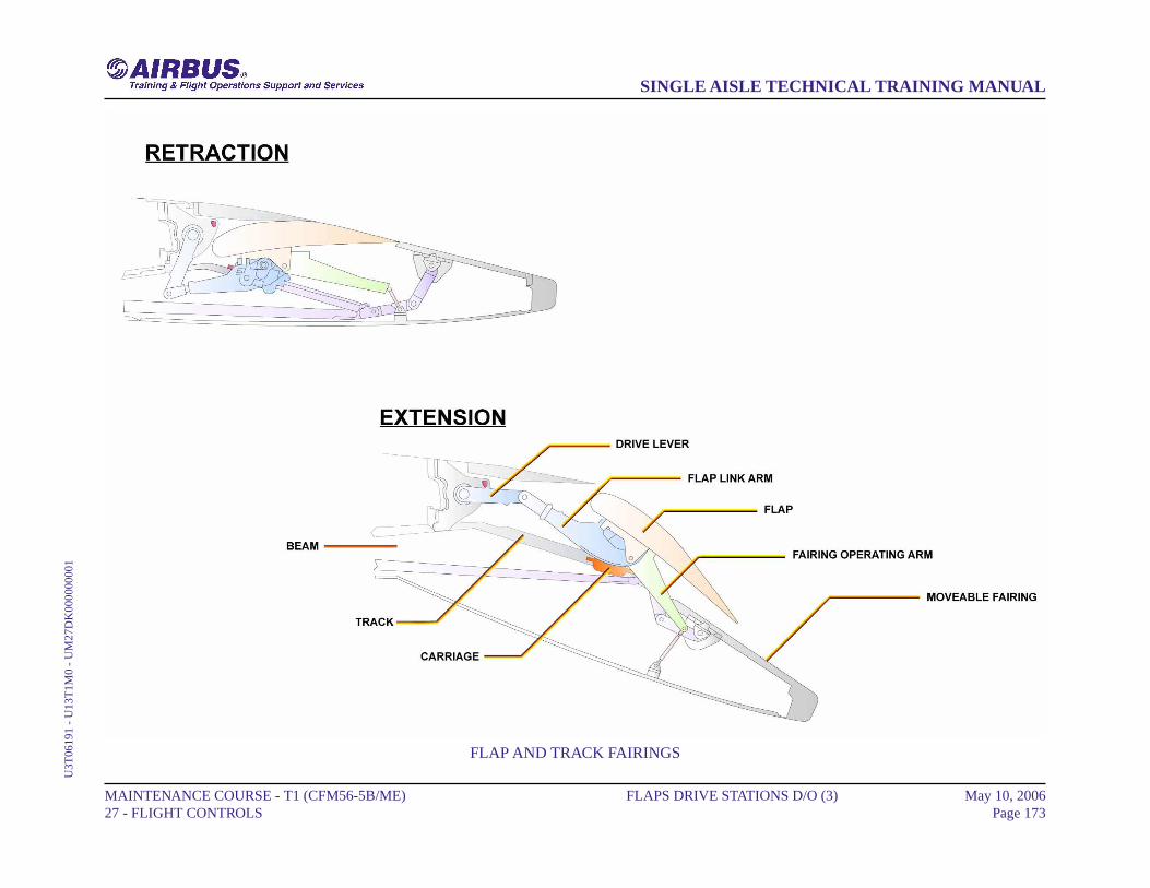
FLAP AND TRACK FAIRINGS
MAINTENANCE COURSE - T1 (CFM56-5B/ME) 27 - FLIGHT CONTROLS
FLAPS DRIVE STATIONS D/O (3) May 10, 2006Page 173
SINGLE AISLE TECHNICAL TRAINING MANUALU
3T06
191
- U
13T
1M0
- U
M27
DK
0000
0000
1
FLAPS DRIVE STATIONS D/O (3) (A321)
GENERAL
Each flap is supported by carriages that run on tracks extending from thewing rear spar. Each carriage has a containment device to hold it on thetrack if a failure occurs. The carriages, tracks and beams at tracks 2, 3and 4 are of similar construction. Track 1 is attached to the fuselage. Ahinge mechanism connects the leading edge of the tab surface to theprimary surface of the flap.
MAINTENANCE COURSE - T1 (CFM56-5B/ME) 27 - FLIGHT CONTROLS
FLAPS DRIVE STATIONS D/O (3) (A321) May 10, 2006Page 174
SINGLE AISLE TECHNICAL TRAINING MANUALU
3T06
191
- U
13T
1M0
- U
M27
DK
0000
0000
2
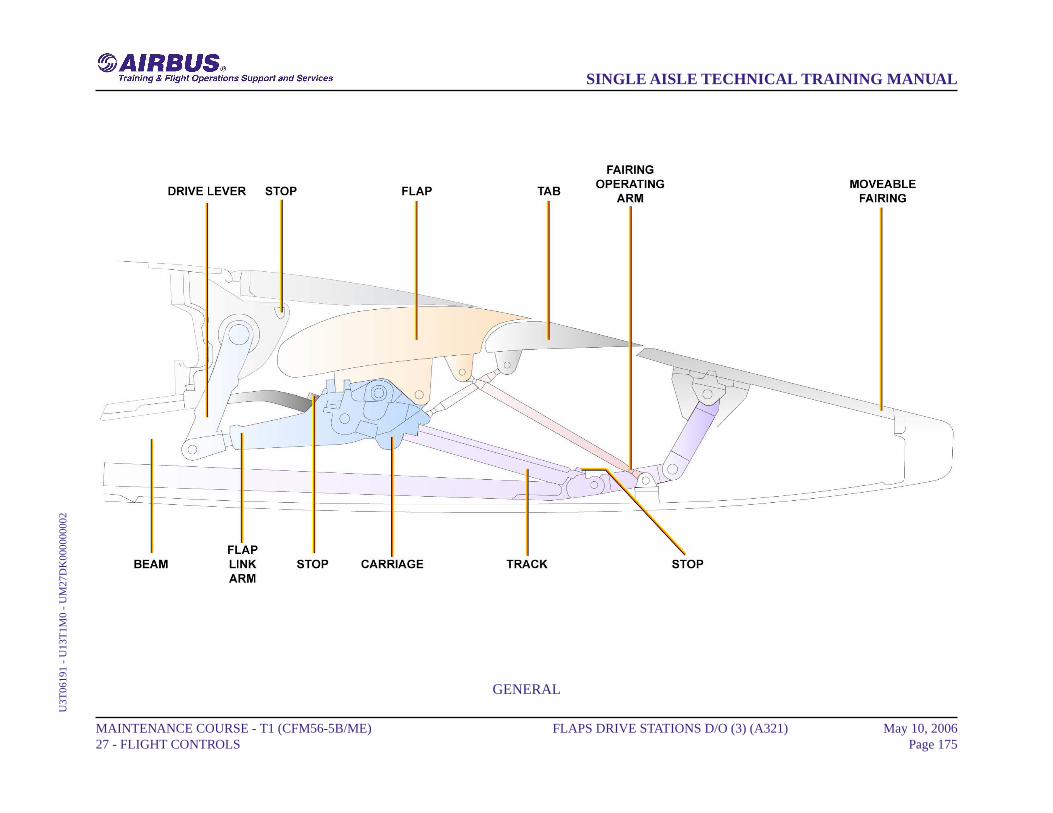
GENERAL
MAINTENANCE COURSE - T1 (CFM56-5B/ME) 27 - FLIGHT CONTROLS
FLAPS DRIVE STATIONS D/O (3) (A321) May 10, 2006Page 175
SINGLE AISLE TECHNICAL TRAINING MANUALU
3T06
191
- U
13T
1M0
- U
M27
DK
0000
0000
2

FLAPS DRIVE STATIONS D/O (3) (A321)
FLAP DRIVES
Six vertical-load and four side-load rollers hold each carriage on its trackat tracks 2, 3 and 4. Only four vertical-load and two side-load rollers holdthe carriage on track 1. A fail-safe hook keeps the flap on the track ifthere is a structural failure of the carriage. Bolts attach the carriage to theflaps. Bolts have eccentrics for flaps rigging.
MAINTENANCE COURSE - T1 (CFM56-5B/ME) 27 - FLIGHT CONTROLS
FLAPS DRIVE STATIONS D/O (3) (A321) May 10, 2006Page 176
SINGLE AISLE TECHNICAL TRAINING MANUALU
3T06
191
- U
13T
1M0
- U
M27
DK
0000
0000
2
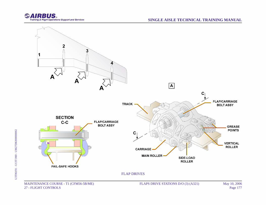
FLAP DRIVES
MAINTENANCE COURSE - T1 (CFM56-5B/ME) 27 - FLIGHT CONTROLS
FLAPS DRIVE STATIONS D/O (3) (A321) May 10, 2006Page 177
SINGLE AISLE TECHNICAL TRAINING MANUALU
3T06
191
- U
13T
1M0
- U
M27
DK
0000
0000
2
FLAPS DRIVE STATIONS D/O (3) (A321)
FLAP AND TRACK FAIRINGS
A flap link arm is attached to the flap bottom surface immediatelyoutboard of each track position. The link arms transmit the movementfrom the rotary actuators to the flap surface. Attached to the flap bottom,at tracks 2, 3 and 4, a track operates the moveable track fairing duringflap movement.
MAINTENANCE COURSE - T1 (CFM56-5B/ME) 27 - FLIGHT CONTROLS
FLAPS DRIVE STATIONS D/O (3) (A321) May 10, 2006Page 178
SINGLE AISLE TECHNICAL TRAINING MANUALU
3T06
191
- U
13T
1M0
- U
M27
DK
0000
0000
2
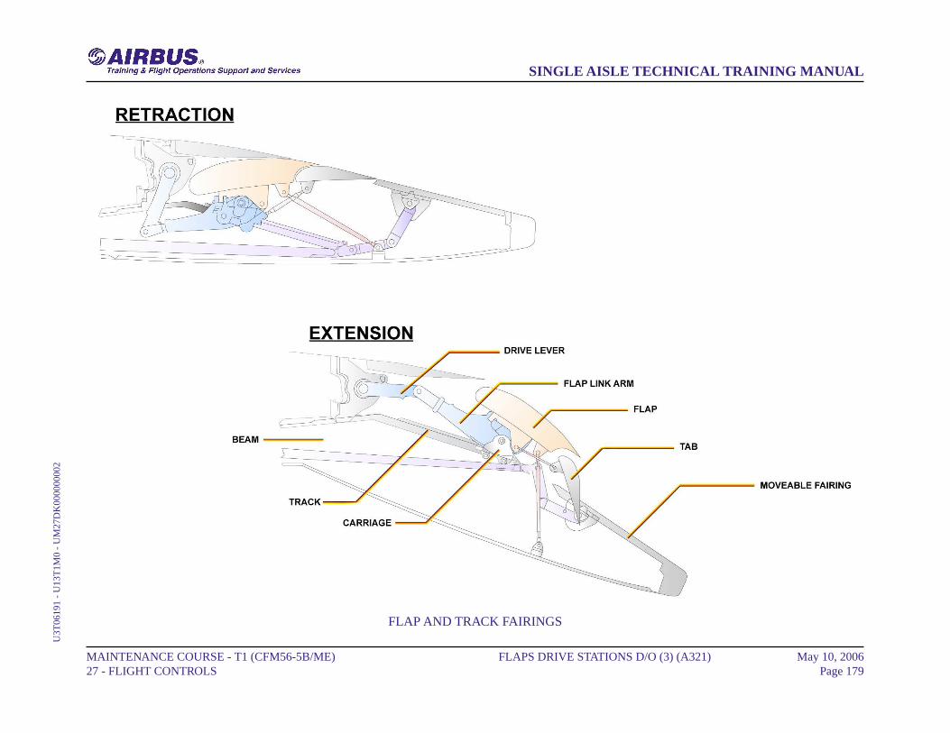
FLAP AND TRACK FAIRINGS
MAINTENANCE COURSE - T1 (CFM56-5B/ME) 27 - FLIGHT CONTROLS
FLAPS DRIVE STATIONS D/O (3) (A321) May 10, 2006Page 179
SINGLE AISLE TECHNICAL TRAINING MANUALU
3T06
191
- U
13T
1M0
- U
M27
DK
0000
0000
2
FLAPS DRIVE STATIONS D/O (3) (A321)
TYPICAL TABS
The inner tab is attached to the rear spar of the flap at track 2 and hinges1A and 1B. The outer tab is attached to the rear spar of the flap at tracks3 and 4 and at hinges 3A, 3B and 3C.When the flaps move, the tabs are operated by a linkage connected from:- the shroud box assembly to hinge 1A tab attachment bracket,- the roller carriages of tracks 2, 3 and 4 to the tab attachment brackets.
MAINTENANCE COURSE - T1 (CFM56-5B/ME) 27 - FLIGHT CONTROLS
FLAPS DRIVE STATIONS D/O (3) (A321) May 10, 2006Page 180
SINGLE AISLE TECHNICAL TRAINING MANUALU
3T06
191
- U
13T
1M0
- U
M27
DK
0000
0000
2

TYPICAL TABS
MAINTENANCE COURSE - T1 (CFM56-5B/ME) 27 - FLIGHT CONTROLS
FLAPS DRIVE STATIONS D/O (3) (A321) May 10, 2006Page 181
SINGLE AISLE TECHNICAL TRAINING MANUALU
3T06
191
- U
13T
1M0
- U
M27
DK
0000
0000
2
FLAPS ATTACHMENT FAILURE DET DESCRIPTION (3)
SENSORS
Two flap disconnect sensors are fitted on the interconnecting strut betweeninner and outer flaps on each wing. The flap disconnect sensors, whichare proximity sensors, detect any flap disconnection.
LGCIUEach Landing Gear Control and Interface Unit (LGCIU) receivessignals from two sensors and transmits this data to its related Slat FlapControl Computer (SFCC). The LGCIUs are used to process signalsfrom proximity sensors.
SFCCThe SFCCs monitor the flap-attachment failure detection sensors tofind connection failure. If the SFCCs receive a flap disconnect signal:- the valve block solenoids on the Power Control Unit (PCU) arede-energized,- the Pressure-Off Brakes (POBs) lock the two hydraulic motors,- the SFCCs give a class 1 level 2 caution and the ECAM display unitshows a failure message.System reset is only possible on the ground. The ECAM display unitshows a failure message if:- the SFCC gets different data from the two sensors on the same wingor,- one sensor gives incorrect data.
MAINTENANCE COURSE - T1 (CFM56-5B/ME) 27 - FLIGHT CONTROLS
FLAPS ATTACHMENT FAILURE DET DESCRIPTION (3) May 10, 2006Page 182
SINGLE AISLE TECHNICAL TRAINING MANUALU
3T06
191
- U
13T
1M0
- U
M27
DJ0
0000
0001
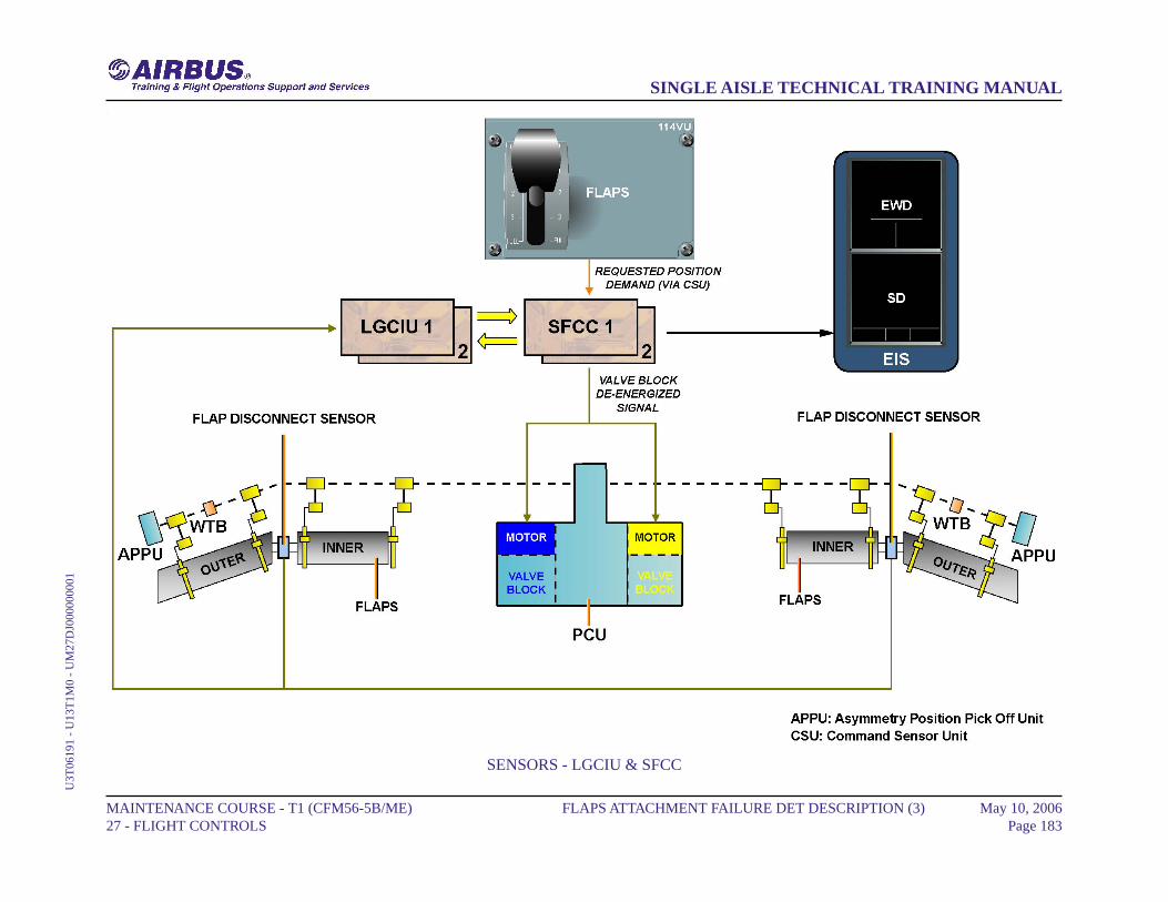
SENSORS - LGCIU & SFCC
MAINTENANCE COURSE - T1 (CFM56-5B/ME) 27 - FLIGHT CONTROLS
FLAPS ATTACHMENT FAILURE DET DESCRIPTION (3) May 10, 2006Page 183
SINGLE AISLE TECHNICAL TRAINING MANUALU
3T06
191
- U
13T
1M0
- U
M27
DJ0
0000
0001
SLATS/FLAPS WARNINGS (3)
SLATS/FLAPS FAULT
In case of slat or flap fault, the MASTER CAUTion comes on, an auralwarning sounds and the S or F indication appears (depending on theconcerned surface) in amber on the upper area of the EWD. The failuremessage is displayed amber on the EWD. In this example, the selectedflap position 2 has not been reached. The position number and the flapposition selection symbol remain cyan, and the green line and F indicationturn to amber.
SLATS/FLAPS LOCKED
In case of locked slat or flap, the MASTER CAUT comes on, an auralwarning sounds and the S-LOCKED or F-LOCKED amber message(depending on the concerned surface) is displayed on the upper area ofthe EWD above the S indication. The failure message is shown amberon the EWD. In this example, the selected slat position 3 has not beenreached. The position number and the slat position selection symbolremain cyan, the green line turns amber and the amber S-LOCKEDmessage comes on above the S indication.
MAINTENANCE COURSE - T1 (CFM56-5B/ME) 27 - FLIGHT CONTROLS
SLATS/FLAPS WARNINGS (3) May 10, 2006Page 184
SINGLE AISLE TECHNICAL TRAINING MANUALU
3T06
191
- U
13T
1M0
- U
M27
W20
0000
0001
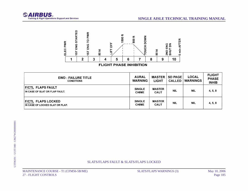
SLATS/FLAPS FAULT & SLATS/FLAPS LOCKED
MAINTENANCE COURSE - T1 (CFM56-5B/ME) 27 - FLIGHT CONTROLS
SLATS/FLAPS WARNINGS (3) May 10, 2006Page 185
SINGLE AISLE TECHNICAL TRAINING MANUALU
3T06
191
- U
13T
1M0
- U
M27
W20
0000
0001
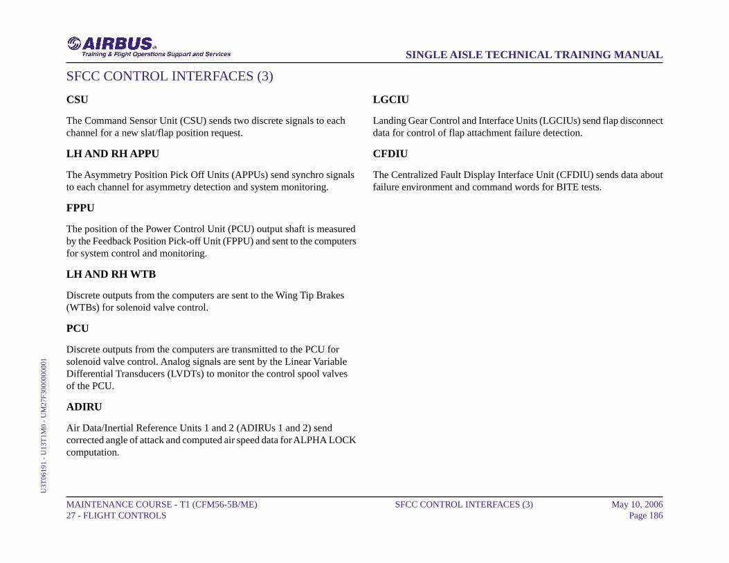
SFCC CONTROL INTERFACES (3)
CSU
The Command Sensor Unit (CSU) sends two discrete signals to eachchannel for a new slat/flap position request.
LH AND RH APPU
The Asymmetry Position Pick Off Units (APPUs) send synchro signalsto each channel for asymmetry detection and system monitoring.
FPPU
The position of the Power Control Unit (PCU) output shaft is measuredby the Feedback Position Pick-off Unit (FPPU) and sent to the computersfor system control and monitoring.
LH AND RH WTB
Discrete outputs from the computers are sent to the Wing Tip Brakes(WTBs) for solenoid valve control.
PCU
Discrete outputs from the computers are transmitted to the PCU forsolenoid valve control. Analog signals are sent by the Linear VariableDifferential Transducers (LVDTs) to monitor the control spool valvesof the PCU.
ADIRU
Air Data/Inertial Reference Units 1 and 2 (ADIRUs 1 and 2) sendcorrected angle of attack and computed air speed data for ALPHA LOCKcomputation.
LGCIU
Landing Gear Control and Interface Units (LGCIUs) send flap disconnectdata for control of flap attachment failure detection.
CFDIU
The Centralized Fault Display Interface Unit (CFDIU) sends data aboutfailure environment and command words for BITE tests.
MAINTENANCE COURSE - T1 (CFM56-5B/ME) 27 - FLIGHT CONTROLS
SFCC CONTROL INTERFACES (3) May 10, 2006Page 186
SINGLE AISLE TECHNICAL TRAINING MANUALU
3T06
191
- U
13T
1M0
- U
M27
F300
0000
001

CSU ... CFDIU
MAINTENANCE COURSE - T1 (CFM56-5B/ME) 27 - FLIGHT CONTROLS
SFCC CONTROL INTERFACES (3) May 10, 2006Page 187
SINGLE AISLE TECHNICAL TRAINING MANUALU
3T06
191
- U
13T
1M0
- U
M27
F300
0000
001
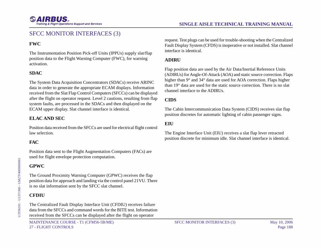
SFCC MONITOR INTERFACES (3)
FWC
The Instrumentation Position Pick-off Units (IPPUs) supply slat/flapposition data to the Flight Warning Computer (FWC), for warningactivation.
SDAC
The System Data Acquisition Concentrators (SDACs) receive ARINCdata in order to generate the appropriate ECAM displays. Informationreceived from the Slat Flap Control Computers (SFCCs) can be displayedafter the flight on operator request. Level 2 cautions, resulting from flapsystem faults, are processed in the SDACs and then displayed on theECAM upper display. Slat channel interface is identical.
ELAC AND SEC
Position data received from the SFCCs are used for electrical flight controllaw selection.
FAC
Position data sent to the Flight Augmentation Computers (FACs) areused for flight envelope protection computation.
GPWC
The Ground Proximity Warning Computer (GPWC) receives the flapposition data for approach and landing via the control panel 21VU. Thereis no slat information sent by the SFCC slat channel.
CFDIU
The Centralized Fault Display Interface Unit (CFDIU) receives failuredata from the SFCCs and command words for the BITE test. Informationreceived from the SFCCs can be displayed after the flight on operator
request. Test plugs can be used for trouble-shooting when the CentralizedFault Display System (CFDS) is inoperative or not installed. Slat channelinterface is identical.
ADIRU
Flap position data are used by the Air Data/Inertial Reference Units(ADIRUs) for Angle-Of-Attack (AOA) and static source correction. Flapshigher than 9° and 34° data are used for AOA correction. Flaps higherthan 19° data are used for the static source correction. There is no slatchannel interface to the ADIRUs.
CIDS
The Cabin Intercommunication Data System (CIDS) receives slat flapposition discretes for automatic lighting of cabin passenger signs.
EIU
The Engine Interface Unit (EIU) receives a slat flap lever retractedposition discrete for minimum idle. Slat channel interface is identical.
MAINTENANCE COURSE - T1 (CFM56-5B/ME) 27 - FLIGHT CONTROLS
SFCC MONITOR INTERFACES (3) May 10, 2006Page 188
SINGLE AISLE TECHNICAL TRAINING MANUALU
3T06
191
- U
13T
1M0
- U
M27
F400
0000
001
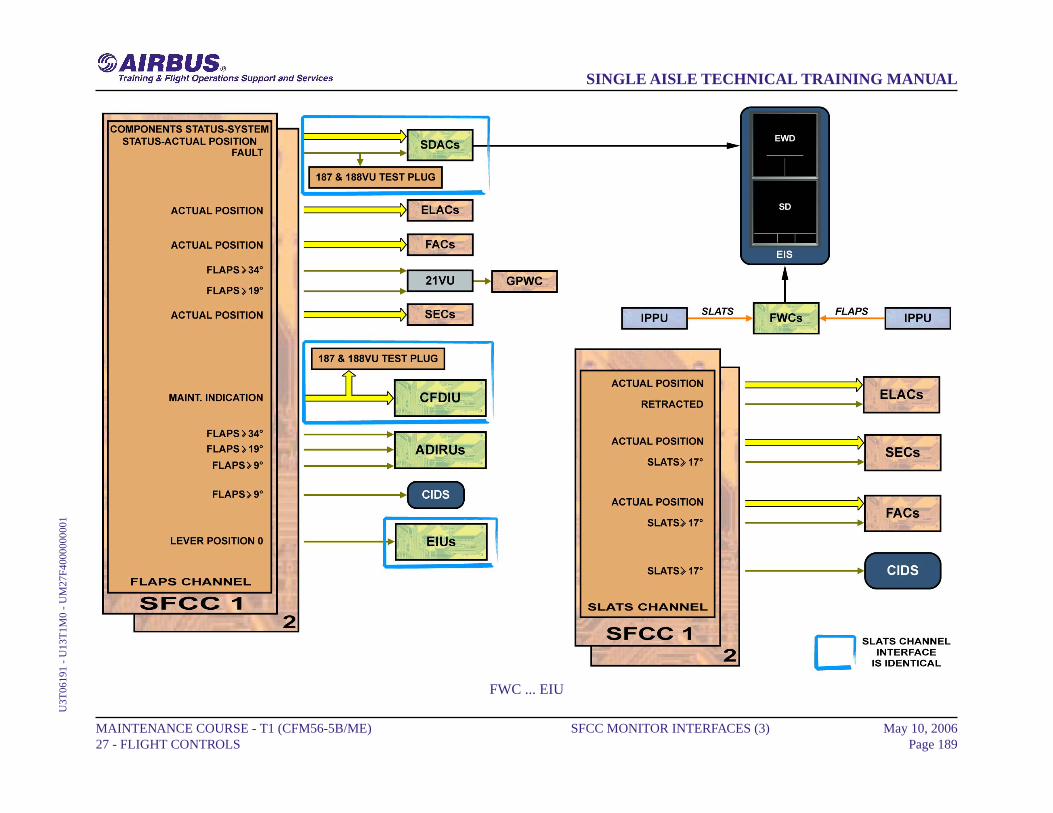
FWC ... EIU
MAINTENANCE COURSE - T1 (CFM56-5B/ME) 27 - FLIGHT CONTROLS
SFCC MONITOR INTERFACES (3) May 10, 2006Page 189
SINGLE AISLE TECHNICAL TRAINING MANUALU
3T06
191
- U
13T
1M0
- U
M27
F400
0000
001

AIRBUS S.A.S.31707 BLAGNAC cedex, FRANCE
STMREFERENCE U3T06191
MAY 2006PRINTED IN FRANCEAIRBUS S.A.S. 2006
ALL RIGHTS RESERVED
AN EADS JOINT COMPANYWITH BAE SYSTEMS