Embed Size (px)
Citation preview

A319/A320/A321TECHNICAL TRAINING MANUAL
MECHANICS / ELECTRICS & AVIONICS COURSE
27 FLIGHT CONTROLS


This document must be used for training purpose only
Under no circumstances should this document be used as a reference.
It will not be updated.
All rights reserved.No part of this manual may be reproduced in any form,
by photostat, microfilm, retrieval system, or any other means,without the prior written permission of Airbus Industrie.

GENERAL** System Presentation (1) 1.......................** Fly By Wire Philosophy (1) 11...................** System Control and Indicating (1) 15...........** E.F.C.S. Presentation (1) 21....................** Control Law Presentation (1) 25.................** Side Stick OPS & Priority Indication (1) 43....** ECAM Page Presentation (1) 61...................
PITCH** Pitch Control Normal D/O (3) 71.................** Pitch Control Abnormal D/O (3) 77...............** Elevator Servo Control Operation (3) 83........** Elevator Components (3) 91......................** THS Actuator Operation (3) 95...................** THS Components (3) 99............................
ROLL/YAW** Roll Control Normal D/O (3) 103.................** Roll Control Abnormal Operation (3) 107........** Yaw Control Normal D/O (3) 111..................** Yaw Control Abnormal D/O (3) 117................** Aileron Servo Control Operation (3) 121........** Aileron Components (3) 127......................** Spoiler Servo Control Operation (3) 131........** Spoiler Components (3) 139......................** Rudder Trim Actuator D/O (3) 143................** Rudder Servo Control Operation (3) 147.........** Rudder Limiter Operation (3) 155................** Yaw Damper Servo Actuator Operation (3) 161....** Rudder Components (FWD) (3) 171.................** Rudder Components (AFT) (3) 181.................** Speed Brake & Ground Spoiler D/O (3) 197.......
EFCS GENERAL** Flight Control Warnings (3) 207.................
** EFCS Control Interface (3) 211..................** EFCS Monitor Interface (3) 239..................** EFCS Components (3) 243.........................
SLATS AND FLAPS SYSTEM** Slats/Flaps System Presentation (1) 255........** Slats/Flaps Control & POSIndication(1)320/319 261............................** Slats/Flaps Control & POSIndication(1)(A321) 277.............................** Slats/Flaps Control (3) 293.....................** Slats/Flaps Abnormal OPS (Locking) (3) 301.....** Slats/Flaps Abnormal OPS (Half Speed) (3) 311..** Slat Mechanical Drive D/O (3) 319...............** Flap Mechanical Drive D/O (3) (A320/A319) 325..** Flap Mechanical Drive D/O (3) (A321) 331.......** Flaps Drive Stations D/O (3) 337................** Flaps Attachment FAIL Detect Principle(3) 345..** Flap Transmission Components (3) 349...........** Slat Transmission Components (3) 361...........** Slats/Flaps Control & Monitoring CMPNTS(3) 373.** Flaps Power Control Unit Components (3) 379....** Slats Power Control Unit Components (3) 383....** Slats/Flaps Warnings (3) 389....................** SFCC Control Interfaces (3) 395.................** SFCC Monitor Interfaces (3) 399.................
MAINTENANCE PRACTICESSPECIFIC PAGES** CFDS Specific Page Presentation (3) 405......
_A319/A320/A321 TECHNICAL TRAINING MANUAL27 FLIGHT CONTROLSMECHANICS / ELECTRICS & AVIONICS COURSE
UFD4200
EFFECTIVITYALL
27 FLIGHT CONTROLS
UFD4200 TABLE OF CONTENTS Page
27 CONTENTSPage i
Dec 31/00

_A319/A320/A321 TECHNICAL TRAINING MANUAL27 FLIGHT CONTROLSMECHANICS / ELECTRICS & AVIONICS COURSE
UFD4200
EFFECTIVITYALL
27 FLIGHT CONTROLS
UFD4200 TABLE OF CONTENTS Page
27 CONTENTSPage ii
Dec 31/00
THIS PAGE INTENTIONALLY LEFT BLANK

27 - FLIGHT CONTROLS
27-00-00 SYSTEM PRESENTATION
CONTENTS:IntroductionPitchRollYawSpeed BrakesGround SpoilersHigh LiftAileron DroopComputersSafety PrecautionsMaintenance PracticesSelf Examination
TMUFCBA02 LEVEL 1
EFFECTIVITY 27-00-00 Page 1Jul 31/00
_A319/A320/A321 TECHNICAL TRAINING MANUAL27 FLIGHT CONTROLSMECHANICS / ELECTRICS & AVIONICS COURSE
UFD4200
Page 1EFFECTIVITYALL
SYSTEM PRESENTATION
INTRODUCTION
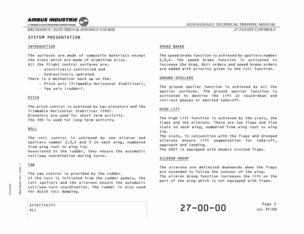
The surfaces are made of composite materials exceptthe slats which are made of aluminium alloy.All the flight control surfaces are:
- electrically controlled and- hydraulically operated.
There is a mechanical back up on the:- Pitch axis (Trimmable Horizontal Stabilizer),- Yaw axis (rudder).
PITCH
The pitch control is achieved by two elevators and theTrimmable Horizontal Stabilizer (THS).Elevators are used for short term activity.The THS is used for long term activity.
ROLL
The roll control is achieved by one aileron andspoilers number 2,3,4 and 5 on each wing, numberedfrom wing root to wing tip.Associated to the rudder, they ensure the automaticroll/yaw coordination during turns.
YAW
The yaw control is provided by the rudder.If the turn is initiated from the rudder pedals, theroll spoilers and the ailerons ensure the automaticroll/yaw turn coordination. The rudder is also usedfor dutch roll damping.
SPEED BRAKE
The speed brake function is achieved by spoilers number2,3,4. The speed brake function is activated toincrease the drag. Roll orders and speed brake ordersare added with priority given to the roll function.
GROUND SPOILERS
The ground spoiler function is achieved by all thespoiler surfaces. The ground spoiler function isactivated to destroy the lift at touch-down androll-out phases or aborted take-off.
HIGH LIFT
The high lift function is achieved by the slats, theflaps and the ailerons. There are two flaps and fiveslats on each wing, numbered from wing root to wingtip.The slats, in conjunction with the flaps and droopedailerons ensure lift augmentation for take-off,approach and landing.The A321 is equipped with double slotted flaps.
AILERON DROOP
The ailerons are deflected downwards when the flapsare extended to follow the contour of the wing.The aileron droop function increases the lift on thepart of the wing which is not equipped with flaps.
TMUFCBA02-T01 LEVEL 1
EFFECTIVITY 27-00-00 Page 2Jul 31/00
_A319/A320/A321 TECHNICAL TRAINING MANUAL27 FLIGHT CONTROLSMECHANICS / ELECTRICS & AVIONICS COURSE
UFD4200
Page 2EFFECTIVITYALL

SYSTEM PRESENTATIONTMUFCBA02-P01 LEVEL 1
EFFECTIVITY 27-00-00 Page 3Jul 31/00
_A319/A320/A321 TECHNICAL TRAINING MANUAL27 FLIGHT CONTROLSMECHANICS / ELECTRICS & AVIONICS COURSE
UFD4200
Page 3EFFECTIVITYALL
SYSTEM PRESENTATION
COMPUTERS
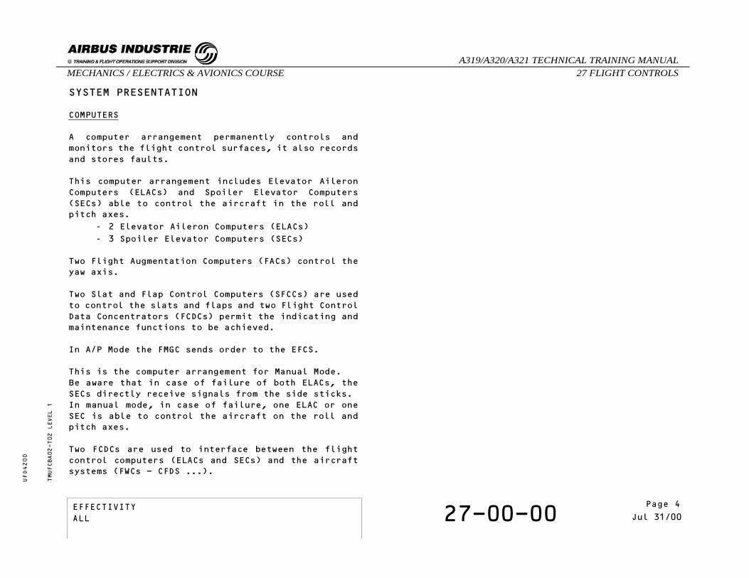
A computer arrangement permanently controls andmonitors the flight control surfaces, it also recordsand stores faults.
This computer arrangement includes Elevator AileronComputers (ELACs) and Spoiler Elevator Computers(SECs) able to control the aircraft in the roll andpitch axes.
- 2 Elevator Aileron Computers (ELACs)- 3 Spoiler Elevator Computers (SECs)
Two Flight Augmentation Computers (FACs) control theyaw axis.
Two Slat and Flap Control Computers (SFCCs) are usedto control the slats and flaps and two Flight ControlData Concentrators (FCDCs) permit the indicating andmaintenance functions to be achieved.
In A/P Mode the FMGC sends order to the EFCS.
This is the computer arrangement for Manual Mode.Be aware that in case of failure of both ELACs, theSECs directly receive signals from the side sticks.In manual mode, in case of failure, one ELAC or oneSEC is able to control the aircraft on the roll andpitch axes.
Two FCDCs are used to interface between the flightcontrol computers (ELACs and SECs) and the aircraftsystems (FWCs - CFDS ...).
TMUFCBA02-T02 LEVEL 1
EFFECTIVITY 27-00-00 Page 4Jul 31/00
_A319/A320/A321 TECHNICAL TRAINING MANUAL27 FLIGHT CONTROLSMECHANICS / ELECTRICS & AVIONICS COURSE
UFD4200
Page 4EFFECTIVITYALL

SYSTEM PRESENTATION - COMPUTER ARRANGEMENTTMUFCBA02-P02 LEVEL 1
EFFECTIVITY 27-00-00 Page 5Jul 31/00
_A319/A320/A321 TECHNICAL TRAINING MANUAL27 FLIGHT CONTROLSMECHANICS / ELECTRICS & AVIONICS COURSE
UFD4200
Page 5EFFECTIVITYALL

SYSTEM PRESENTATION
COMPUTERS (CONT’D)
The ELACs, SECs and FACs elaborate the flight controllaws, including flight envelope protection whichoptimize the control of the A/C.
TMUFCBA02-T03 LEVEL 1
EFFECTIVITY 27-00-00 Page 6Jul 31/00
_A319/A320/A321 TECHNICAL TRAINING MANUAL27 FLIGHT CONTROLSMECHANICS / ELECTRICS & AVIONICS COURSE
UFD4200
Page 6EFFECTIVITYALL

TMUFCBA02-P03 LEVEL 1
SYSTEM PRESENTATION - COMPUTERS (CONT’D)
EFFECTIVITY 27-00-00 Page 7Jul 31/00
_A319/A320/A321 TECHNICAL TRAINING MANUAL27 FLIGHT CONTROLSMECHANICS / ELECTRICS & AVIONICS COURSE
UFD4200
Page 7EFFECTIVITYALL

SAFETY PRECAUTIONS
The precautions to be taken before operating the flightcontrol surfaces are:
- WARNING: Put safety devices and a warningnotice in position.
- WARNING: Make sure that the travel ranges ofthe surfaces are clear before youpressurize/depressurize a hydraulicsystem.
- WARNING: Make sure that the controls agreewith the position of the items theyoperate before you pressurize ahydraulic system.
- WARNING: Make sure that the landing gearsafety locks and the wheel chocks arein position.
MAINTENANCE PRACTICES
Rigging has to be performed on the three axes includingthe slats and flaps.
TMUFCBA02-T04 LEVEL 1
EFFECTIVITY 27-00-00 Page 8Jul 31/00
_A319/A320/A321 TECHNICAL TRAINING MANUAL27 FLIGHT CONTROLSMECHANICS / ELECTRICS & AVIONICS COURSE
UFD4200
Page 8EFFECTIVITYALL

SELF EXAMINATION
Which surfaces are used for lift dumping?A - All spoilersB - Spoilers 1 to 3C - Spoilers 1 to 4
Which surfaces are used to control the roll?A - Spoilers 1 to 5B - Ailerons and spoilers 3 to 5C - Ailerons and spoilers 2 to 5.
TMUFCBA02 LEVEL 1
EFFECTIVITY 27-00-00 Page 9Jul 31/00
_A319/A320/A321 TECHNICAL TRAINING MANUAL27 FLIGHT CONTROLSMECHANICS / ELECTRICS & AVIONICS COURSE
UFD4200
Page 9EFFECTIVITYALL

THIS PAGE INTENTIONALLY LEFT BLANK
TMUFCBA02 LEVEL 1
EFFECTIVITY 27-00-00 Page 10Jul 31/00
_A319/A320/A321 TECHNICAL TRAINING MANUAL27 FLIGHT CONTROLSMECHANICS / ELECTRICS & AVIONICS COURSE
UFD4200
Page 10EFFECTIVITYALL

27 - FLIGHT CONTROLS
27-90-00 FLY BY WIRE PHILOSOPHY
CONTENTSGeneralControl ColumnMechanical LinkageAutopilot ServoArtificial FeelServo ActuatorControl Wheel Steering Function
TMUFCLC02 LEVEL 1
EFFECTIVITY 27-90-00 Page 1Jun 30/97
_A319/A320/A321 TECHNICAL TRAINING MANUAL27 FLIGHT CONTROLSMECHANICS / ELECTRICS & AVIONICS COURSE
UFD4200
Page 11EFFECTIVITYALL

FLY BY WIRE PHILOSOPHY
GENERAL
All the flight control surfaces are now electricallycontrolled and hydraulically operated. In addition,the stabilizer and the rudder have an hydromechanicalcontrol back-up in case of electrical failure.The main advantage of this philosophy is an improvementin redundancy, in handling qualities, in weight savingand thus in performance.
CONTROL COLUMN
The control column has been replaced by the side stick.
MECHANICAL LINKAGE
The mechanical channel is replaced by electrical wiringand computers. These computers control theservo-actuators.The computers elaborate the flight control laws,including flight envelope protection, which optimizethe control of the aircraft.
AUTOPILOT SERVO
The autopilot commands are directly transmitted to thecomputers.
ARTIFICIAL FEEL
The modulated artificial feel is replaced by the sidestick centering spring.
SERVO ACTUATOR
The mechanical feedback of the conventionalservoactuator is replaced by an electrical feedbackto the computers.
CONTROL WHEEL STEERING FUNCTION
The Control Wheel Steering (CWS) function is ensuredby the computers which use the aircraft response tomaintain the required attitude.
TMUFCLC02-T01 LEVEL 1
EFFECTIVITY 27-90-00 Page 2Jun 30/97
_A319/A320/A321 TECHNICAL TRAINING MANUAL27 FLIGHT CONTROLSMECHANICS / ELECTRICS & AVIONICS COURSE
UFD4200
Page 12EFFECTIVITYALL

FLY BY WIRE PHILOSOPHYTMUFCLC02-P01 LEVEL 1
EFFECTIVITY 27-90-00 Page 3Jun 30/97
_A319/A320/A321 TECHNICAL TRAINING MANUAL27 FLIGHT CONTROLSMECHANICS / ELECTRICS & AVIONICS COURSE
UFD4200
Page 13EFFECTIVITYALL

THIS PAGE INTENTIONALLY LEFT BLANK
TMUFCLC02 LEVEL 1
EFFECTIVITY 27-90-00 Page 4Jun 30/97
_A319/A320/A321 TECHNICAL TRAINING MANUAL27 FLIGHT CONTROLSMECHANICS / ELECTRICS & AVIONICS COURSE
UFD4200
Page 14EFFECTIVITYALL

27 - FLIGHT CONTROLS
27-00-00 SYSTEM CONTROL AND INDICATING
CONTENTS:Side SticksSpeed Brake LeverTHS Mechanical ControlRudder PedalsSlat/Flap Control LeverRudder TrimFlight Control PanelsECAM Pages
TMUFCBB04 LEVEL 1
EFFECTIVITY 27-00-00 Page 1Mar 31/00
_A319/A320/A321 TECHNICAL TRAINING MANUAL27 FLIGHT CONTROLSMECHANICS / ELECTRICS & AVIONICS COURSE
UFD4200
Page 15EFFECTIVITYALL
SYSTEM CONTROL AND INDICATING
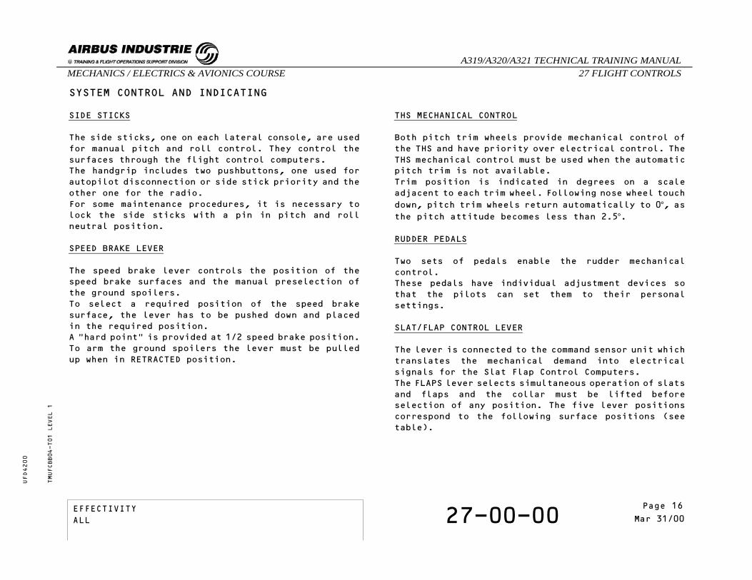
SIDE STICKS
The side sticks, one on each lateral console, are usedfor manual pitch and roll control. They control thesurfaces through the flight control computers.The handgrip includes two pushbuttons, one used forautopilot disconnection or side stick priority and theother one for the radio.For some maintenance procedures, it is necessary tolock the side sticks with a pin in pitch and rollneutral position.
SPEED BRAKE LEVER
The speed brake lever controls the position of thespeed brake surfaces and the manual preselection ofthe ground spoilers.To select a required position of the speed brakesurface, the lever has to be pushed down and placedin the required position. A "hard point" is provided at 1/2 speed brake position.To arm the ground spoilers the lever must be pulledup when in RETRACTED position.
THS MECHANICAL CONTROL
Both pitch trim wheels provide mechanical control ofthe THS and have priority over electrical control. TheTHS mechanical control must be used when the automaticpitch trim is not available.Trim position is indicated in degrees on a scaleadjacent to each trim wheel. Following nose wheel touchdown, pitch trim wheels return automatically to 0°, asthe pitch attitude becomes less than 2.5°.
RUDDER PEDALS
Two sets of pedals enable the rudder mechanicalcontrol.These pedals have individual adjustment devices sothat the pilots can set them to their personalsettings.
SLAT/FLAP CONTROL LEVER
The lever is connected to the command sensor unit whichtranslates the mechanical demand into electricalsignals for the Slat Flap Control Computers.The FLAPS lever selects simultaneous operation of slatsand flaps and the collar must be lifted beforeselection of any position. The five lever positionscorrespond to the following surface positions (seetable).
TMUFCBB04-T01 LEVEL 1
EFFECTIVITY 27-00-00 Page 2Mar 31/00
_A319/A320/A321 TECHNICAL TRAINING MANUAL27 FLIGHT CONTROLSMECHANICS / ELECTRICS & AVIONICS COURSE
UFD4200
Page 16EFFECTIVITYALL

SYSTEM CONTROL AND INDICATING
TMUFCBB04-P01 LEVEL 1
EFFECTIVITY 27-00-00 Page 3Mar 31/00
_A319/A320/A321 TECHNICAL TRAINING MANUAL27 FLIGHT CONTROLSMECHANICS / ELECTRICS & AVIONICS COURSE
UFD4200
Page 17EFFECTIVITYALL

SYSTEM CONTROL AND INDICATING
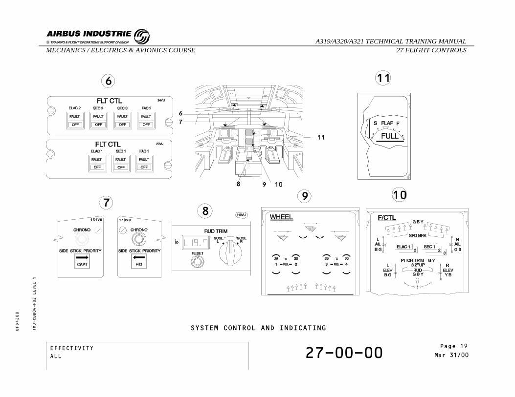
RUDDER TRIM
The rudder trim order is transmitted to the trimactuator through the Flight Augmentation Computers.1 - Rudder trim reset pushbutton switch (Resets thetrim position to zero).2 - Rudder trim control switch (Controls the ruddertrim actuator which moves the neutral point of theartificial feel).3 - Rudder trim indicator (Displays rudder trimdirection L or R and value 0º to 20º).
FLIGHT CONTROL PANELS
The computer pushbuttons serve to energize,de-energize and reset the Elevator and AileronComputers(ELACs), the Spoiler Elevator Computers(SECs) and the Flight Augmentation Computers (FACs).
OFF : In white, when the corresponding computer isswitched off.
FAULT : Comes on amber, accompanied by an ECAM cautionactivation, when a failure is detected. TheFAULT light goes off when OFF is selected.
The side stick priority lights indicate the loss ofpriority and the taking of priority in front of thepilots.
When both side sticks are activated, without anyactions on the priority switch, both the CAPT and F/Ogreen lights come on.The red arrow light comes on in front of the pilotlosing priority. CAPT or F/O green light, comes on in front of the pilottaking priority if the deactivated side stick is notat neutral.
ECAM PAGES
The flight control system uses three ECAM pages, theflight control ECAM page and the wheel ECAM page forthe primary surface indication, and the engine warningdisplay for the slat and flap indications.
TMUFCBB04-T02 LEVEL 1
EFFECTIVITY 27-00-00 Page 4Mar 31/00
_A319/A320/A321 TECHNICAL TRAINING MANUAL27 FLIGHT CONTROLSMECHANICS / ELECTRICS & AVIONICS COURSE
UFD4200
Page 18EFFECTIVITYALL
SYSTEM CONTROL AND INDICATINGTMUFCBB04-P02 LEVEL 1
EFFECTIVITY 27-00-00 Page 5Mar 31/00
_A319/A320/A321 TECHNICAL TRAINING MANUAL27 FLIGHT CONTROLSMECHANICS / ELECTRICS & AVIONICS COURSE
UFD4200
Page 19EFFECTIVITYALL

THIS PAGE LEFT INTENTIONALLY BLANK
TMUFCBB04 LEVEL 1
EFFECTIVITY 27-00-00 Page 6Mar 31/00
_A319/A320/A321 TECHNICAL TRAINING MANUAL27 FLIGHT CONTROLSMECHANICS / ELECTRICS & AVIONICS COURSE
UFD4200
Page 20EFFECTIVITYALL

27 - FLIGHT CONTROLS
27-00-00 EFCS PRESENTATION
CONTENTS:SurfacesActuatorsComputersActive servo controlsReconfiguration PrioritiesSelf examination
TMUFCLD02 LEVEL 1
EFFECTIVITY 27-00-00 Page 1Mar 31/94
_A319/A320/A321 TECHNICAL TRAINING MANUAL27 FLIGHT CONTROLSMECHANICS / ELECTRICS & AVIONICS COURSE
UFD4200
Page 21EFFECTIVITYALL
EFCS PRESENTATION
SURFACES
All the flight control surfaces are hydraulicallyoperated by actuators which receive electrical signalsfrom the computers. The rudder and the TrimmableHorizontal Stabilizer (THS) can also be mechanicallycontrolled.
ACTUATORS
All the actuators are hydraulically powered by one ofthe three hydraulic circuits, except the rudder trimactuator, the rudder travel limitation actuator andthe THS servo-motors which are electrically driven.
COMPUTERS
The relationship between actuators and computers isindicated on the schematic. The left or right elevatoractuators are connected to two computers, one ELAC andone SEC
- ELAC: ELevator Aileron Computer- SEC: Spoiler Elevator Computer
ACTIVE SERVO CONTROLS
There are two servo controls for each aileron, foreach elevator and for the yaw damping function. Innormal configuration, one servo control actuates thesurface. It is called active servo control. The second,which follows the surface deflection, is in dampingmode.
When only manual pitch trim is available, the centeringmode is applied to the elevators. The actuators arehydraulically maintained in neutral position.
RECONFIGURATION PRIORITIES
In case of failure, the damping servo control andrelated computer are set to the active mode.
TMUFCLD02-T01 LEVEL 1
EFFECTIVITY 27-00-00 Page 2Mar 31/94
_A319/A320/A321 TECHNICAL TRAINING MANUAL27 FLIGHT CONTROLSMECHANICS / ELECTRICS & AVIONICS COURSE
UFD4200
Page 22EFFECTIVITYALL

EFCS PRESENTATIONTMUFCLD02-P01 LEVEL 1
EFFECTIVITY 27-00-00 Page 3Mar 31/94
_A319/A320/A321 TECHNICAL TRAINING MANUAL27 FLIGHT CONTROLSMECHANICS / ELECTRICS & AVIONICS COURSE
UFD4200
Page 23EFFECTIVITYALL

SELF EXAMINATION
Which surfaces can be mechanically controlled ?A - Elevators and THS.B - Ailerons and THS.C - Rudder and THS.
TMUFCLD02 LEVEL 1
EFFECTIVITY 27-00-00 Page 4Mar 31/94
_A319/A320/A321 TECHNICAL TRAINING MANUAL27 FLIGHT CONTROLSMECHANICS / ELECTRICS & AVIONICS COURSE
UFD4200
Page 24EFFECTIVITYALL
27 - FLIGHT CONTROLS
27-90-00 CONTROL LAW PRESENTATION
CONTENTS:Normal LawsLaw ReconfigurationsAlternate lawsDirect lawMechanical Back-upSelf Examination
TMUFCBC01 LEVEL 1
EFFECTIVITY 27-90-00 Page 1May 31/00
_A319/A320/A321 TECHNICAL TRAINING MANUAL27 FLIGHT CONTROLSMECHANICS / ELECTRICS & AVIONICS COURSE
UFD4200
Page 25EFFECTIVITYALL

CONTROL LAW PRESENTATION
NORMAL LAWS
In normal conditions, the normal laws are used tocompute the surface deflection orders.Normal laws provide a FULL FLIGHT ENVELOPE PROTECTION.
TMUFCBC01-T01 LEVEL 1
EFFECTIVITY 27-90-00 Page 2May 31/00
_A319/A320/A321 TECHNICAL TRAINING MANUAL27 FLIGHT CONTROLSMECHANICS / ELECTRICS & AVIONICS COURSE
UFD4200
Page 26EFFECTIVITYALL

CONTROL LAW PRESENTATION - NORMAL LAWS - BASIC PRINCIPLETMUFCBC01-P01 LEVEL 1
EFFECTIVITY 27-90-00 Page 3May 31/00
_A319/A320/A321 TECHNICAL TRAINING MANUAL27 FLIGHT CONTROLSMECHANICS / ELECTRICS & AVIONICS COURSE
UFD4200
Page 27EFFECTIVITYALL

CONTROL LAW PRESENTATION
NORMAL LAWS (CONTINUED)
There are three principal control modes:- the ground mode,- the flight mode,- and the flare mode.
During the ground mode, a direct relationship existsbetween the stick, elevators and roll control surfaces.Also, the rudder is mechanically controlled by thepedals and the yaw damper function is available. The ground mode is activated after the flare mode whenthe main landing gear shock absorbers are compressedwith pitch attitude confirmation.
In flight mode, the NORMAL LAWS are:- Nz law for the pitch control, including loadfactor protection,
- lateral normal law for the lateralcontrol(roll+yaw), including bank angleprotection,
- highspeed (VMO),- pitch attitude (Theta),- and stall (Angle Of Attack) protections.
The flight mode is activated after the ground modewhen the main landing gear shock absorbers are extendedwith pitch attitude confirmation.
The NORMAL LAWS in flare mode are:- flare law in place of Nz law for the pitchcontrol to allow conventional flare,
- lateral normal law,- and stall protection.
The flare mode is activated after the flight mode belowa certain altitude.
TMUFCBC01-T02 LEVEL 1
EFFECTIVITY 27-90-00 Page 4May 31/00
_A319/A320/A321 TECHNICAL TRAINING MANUAL27 FLIGHT CONTROLSMECHANICS / ELECTRICS & AVIONICS COURSE
UFD4200
Page 28EFFECTIVITYALL

CONTROL LAW PRESENTATION - NORMAL LAWSTMUFCBC01-P02 LEVEL 1
EFFECTIVITY 27-90-00 Page 5May 31/00
_A319/A320/A321 TECHNICAL TRAINING MANUAL27 FLIGHT CONTROLSMECHANICS / ELECTRICS & AVIONICS COURSE
UFD4200
Page 29EFFECTIVITYALL

CONTROL LAW PRESENTATION
LAW RECONFIGURATIONS
The reconfiguration of control laws in pitch axis andin lateral axis.Control law reconfigurations are divided into twofamilies:
- ALTERNATE- DIRECT
There is no loss of normal law after a single failure.The transfer from normal to alternate laws is automaticand depends on the number and nature of failures.
TMUFCBC01-T03 LEVEL 1
EFFECTIVITY 27-90-00 Page 6May 31/00
_A319/A320/A321 TECHNICAL TRAINING MANUAL27 FLIGHT CONTROLSMECHANICS / ELECTRICS & AVIONICS COURSE
UFD4200
Page 30EFFECTIVITYALL

CONTROL LAW PRESENTATION - LAW RECONFIGURATIONTMUFCBC01-P03 LEVEL 1
EFFECTIVITY 27-90-00 Page 7May 31/00
_A319/A320/A321 TECHNICAL TRAINING MANUAL27 FLIGHT CONTROLSMECHANICS / ELECTRICS & AVIONICS COURSE
UFD4200
Page 31EFFECTIVITYALL

CONTROL LAW PRESENTATION
ALTERNATE LAWS
The alternate laws are automatically introduced assoon as the normal laws are lost.The alternate laws provide, for the pitch axis:
- load factor protection,- high and low speed stability (alternate highspeed protection and alternate high angle ofattack protection).
The roll axis is in direct law.
TMUFCBC01-T04 LEVEL 1
EFFECTIVITY 27-90-00 Page 8May 31/00
_A319/A320/A321 TECHNICAL TRAINING MANUAL27 FLIGHT CONTROLSMECHANICS / ELECTRICS & AVIONICS COURSE
UFD4200
Page 32EFFECTIVITYALL

CONTROL LAW PRESENTATION - ALTERNATE LAW WITH REDUCED PROTECTIONSTMUFCBC01-P04 LEVEL 1
EFFECTIVITY 27-90-00 Page 9May 31/00
_A319/A320/A321 TECHNICAL TRAINING MANUAL27 FLIGHT CONTROLSMECHANICS / ELECTRICS & AVIONICS COURSE
UFD4200
Page 33EFFECTIVITYALL

CONTROL LAW PRESENTATION
ALTERNATE LAWS
In alternate law without protection, the high and lowspeed stability are lost.Only the load factor limitation is provided.
TMUFCBC01-T05 LEVEL 1
EFFECTIVITY 27-90-00 Page 10May 31/00
_A319/A320/A321 TECHNICAL TRAINING MANUAL27 FLIGHT CONTROLSMECHANICS / ELECTRICS & AVIONICS COURSE
UFD4200
Page 34EFFECTIVITYALL

CONTROL LAW PRESENTATION - ALTERNATE LAW WITHOUT PROTECTIONTMUFCBC01-P05 LEVEL 1
EFFECTIVITY 27-90-00 Page 11May 31/00
_A319/A320/A321 TECHNICAL TRAINING MANUAL27 FLIGHT CONTROLSMECHANICS / ELECTRICS & AVIONICS COURSE
UFD4200
Page 35EFFECTIVITYALL

CONTROL LAW PRESENTATION
DIRECT LAW
This law is automatically activated on ground.The direct law can be activated in flight followingfailures if the normal and the alternate laws can nolonger be performed.
TMUFCBC01-T06 LEVEL 1
EFFECTIVITY 27-90-00 Page 12May 31/00
_A319/A320/A321 TECHNICAL TRAINING MANUAL27 FLIGHT CONTROLSMECHANICS / ELECTRICS & AVIONICS COURSE
UFD4200
Page 36EFFECTIVITYALL

CONTROL LAW PRESENTATION - DIRECT LAWTMUFCBC01-P06 LEVEL 1
EFFECTIVITY 27-90-00 Page 13May 31/00
_A319/A320/A321 TECHNICAL TRAINING MANUAL27 FLIGHT CONTROLSMECHANICS / ELECTRICS & AVIONICS COURSE
UFD4200
Page 37EFFECTIVITYALL

CONTROL LAW PRESENTATION
DIRECT LAW
A direct relationship between the side stick and thesurfaces is used.In direct law, all the protections are lost.
TMUFCBC01-T07 LEVEL 1
EFFECTIVITY 27-90-00 Page 14May 31/00
_A319/A320/A321 TECHNICAL TRAINING MANUAL27 FLIGHT CONTROLSMECHANICS / ELECTRICS & AVIONICS COURSE
UFD4200
Page 38EFFECTIVITYALL

CONTROL LAW PRESENTATION - DIRECT LAW - BASIC PRINCIPLETMUFCBC01-P07 LEVEL 1
EFFECTIVITY 27-90-00 Page 15May 31/00
_A319/A320/A321 TECHNICAL TRAINING MANUAL27 FLIGHT CONTROLSMECHANICS / ELECTRICS & AVIONICS COURSE
UFD4200
Page 39EFFECTIVITYALL

CONTROL LAW PRESENTATION
MECHANICAL BACK-UP
The mechanical back-up permits the aircraft to becontrolled during a temporary complete loss ofelectrical power or flight controls computers.The longitudinal control is achieved using the trimwheels as the elevators are kept at zero deflection.The lateral control is achieved from pedals.
TMUFCBC01-T08 LEVEL 1
EFFECTIVITY 27-90-00 Page 16May 31/00
_A319/A320/A321 TECHNICAL TRAINING MANUAL27 FLIGHT CONTROLSMECHANICS / ELECTRICS & AVIONICS COURSE
UFD4200
Page 40EFFECTIVITYALL

CONTROL LAW PRESENTATION - MECHANICAL BACK-UPTMUFCBC01-P08 LEVEL 1
EFFECTIVITY 27-90-00 Page 17May 31/00
_A319/A320/A321 TECHNICAL TRAINING MANUAL27 FLIGHT CONTROLSMECHANICS / ELECTRICS & AVIONICS COURSE
UFD4200
Page 41EFFECTIVITYALL

SELF EXAMINATION
In normal conditions, what are the activeprotections in flare mode?
A - Bank angle and stall protections.B - Bank angle and high speed protections.C - Stall protection only.
What are the active protections in direct law?A - Stall protection only.B - No protection.C - High speed protection.
TMUFCBC01 LEVEL 1
EFFECTIVITY 27-90-00 Page 18May 31/00
_A319/A320/A321 TECHNICAL TRAINING MANUAL27 FLIGHT CONTROLSMECHANICS / ELECTRICS & AVIONICS COURSE
UFD4200
Page 42EFFECTIVITYALL
27 - FLIGHT CONTROLS
27-00-00 SIDE STICK OPERATION ANDPRIORITY INDICATION
CONTENTS:IntroductionPriority LogicAutopilot DisconnectionSelf Examination
TMUFC1103 LEVEL 1
EFFECTIVITY 27-00-00 Page 1Jul 31/00
_A319/A320/A321 TECHNICAL TRAINING MANUAL27 FLIGHT CONTROLSMECHANICS / ELECTRICS & AVIONICS COURSE
UFD4200
Page 43EFFECTIVITYALL
SIDE STICK OPERATION AND PRIORITY INDICATION
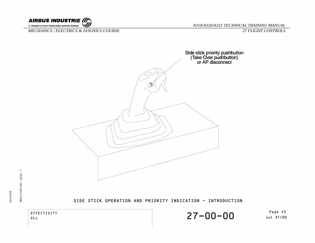
INTRODUCTION
The Captain and the First Officer side stick assembliesare similar. Their ergonomic characteristics areadapted for use with the left hand at the Captain’sstation and with the right hand at the First Officer’sstation.When a side stick is not used, it is springloaded toneutral position.
TMUFC1103-T01 LEVEL 1
EFFECTIVITY 27-00-00 Page 2Jul 31/00
_A319/A320/A321 TECHNICAL TRAINING MANUAL27 FLIGHT CONTROLSMECHANICS / ELECTRICS & AVIONICS COURSE
UFD4200
Page 44EFFECTIVITYALL
SIDE STICK OPERATION AND PRIORITY INDICATION - INTRODUCTIONTMUFC1103-P01 LEVEL 1
EFFECTIVITY 27-00-00 Page 3Jul 31/00
_A319/A320/A321 TECHNICAL TRAINING MANUAL27 FLIGHT CONTROLSMECHANICS / ELECTRICS & AVIONICS COURSE
UFD4200
Page 45EFFECTIVITYALL

SIDE STICK OPERATION AND PRIORITY INDICATION
PRIORITY LOGIC
This logic is achieved in the Flight Control Computers(Elevator Aileron Computers and Spoiler ElevatorComputers).
The CAPT side stick is moved first.When a side stick is moved, an electrical signalrelated to its angle deflection is sent to the systemcomputers.
TMUFC1103-T02 LEVEL 1
EFFECTIVITY 27-00-00 Page 4Jul 31/00
_A319/A320/A321 TECHNICAL TRAINING MANUAL27 FLIGHT CONTROLSMECHANICS / ELECTRICS & AVIONICS COURSE
UFD4200
Page 46EFFECTIVITYALL

SIDE STICK OPERATION AND PRIORITY INDICATION - PRIORITY LOGICTMUFC1103-P02 LEVEL 1
EFFECTIVITY 27-00-00 Page 5Jul 31/00
_A319/A320/A321 TECHNICAL TRAINING MANUAL27 FLIGHT CONTROLSMECHANICS / ELECTRICS & AVIONICS COURSE
UFD4200
Page 47EFFECTIVITYALL

SIDE STICK OPERATION AND PRIORITY INDICATION
PRIORITY LOGIC
When both side sticks are deflected with no action onany priority switch, the two green priority lights(CAPT and F/O) flash and the aural indication "DUALINPUT" is generated every 5 seconds, as long as bothside sticks remain deflected.When both side sticks are moved in the same direction,the signals are algebrically added. The sum is limitedto the surface maximum deflection.
TMUFC1103-T03 LEVEL 1
EFFECTIVITY 27-00-00 Page 6Jul 31/00
_A319/A320/A321 TECHNICAL TRAINING MANUAL27 FLIGHT CONTROLSMECHANICS / ELECTRICS & AVIONICS COURSE
UFD4200
Page 48EFFECTIVITYALL

TMUFC1103-P03 LEVEL 1
SIDE STICK OPERATION AND PRIORITY INDICATION - PRIORITY LOGIC
EFFECTIVITY 27-00-00 Page 7Jul 31/00
_A319/A320/A321 TECHNICAL TRAINING MANUAL27 FLIGHT CONTROLSMECHANICS / ELECTRICS & AVIONICS COURSE
UFD4200
Page 49EFFECTIVITYALL

SIDE STICK OPERATION AND PRIORITY INDICATION
PRIORITY LOGIC
If the side sticks are moved in opposite directions,the resulting demand is the difference between them.
TMUFC1103-T04 LEVEL 1
EFFECTIVITY 27-00-00 Page 8Jul 31/00
_A319/A320/A321 TECHNICAL TRAINING MANUAL27 FLIGHT CONTROLSMECHANICS / ELECTRICS & AVIONICS COURSE
UFD4200
Page 50EFFECTIVITYALL

SIDE STICK OPERATION AND PRIORITY INDICATION - PRIORITY LOGICTMUFC1103-P04 LEVEL 1
EFFECTIVITY 27-00-00 Page 9Jul 31/00
_A319/A320/A321 TECHNICAL TRAINING MANUAL27 FLIGHT CONTROLSMECHANICS / ELECTRICS & AVIONICS COURSE
UFD4200
Page 51EFFECTIVITYALL

SIDE STICK OPERATION AND PRIORITY INDICATION
PRIORITY LOGIC
By pressing in and holding his take over pushbutton,the Captain will deactivate the other side stick. Ared light will come on in front of the First Officerwhose stick is deactivated, accompanied by an audiocall out: “PRIORITY LEFT”. A green light will come onin front of the Captain who has taken control when thedeactivated side stick is not in the neutral position.The same logic applies if the First Officer activateshis take over pushbutton.
Keeping the take over p/b pressed in for more than 30seconds will latch the system and maintain thepriority.
At any time, momentarilly pressing the take overpushbutton of the other side stick will reset thesystem.
TMUFC1103-T05 LEVEL 1
EFFECTIVITY 27-00-00 Page 10Jul 31/00
_A319/A320/A321 TECHNICAL TRAINING MANUAL27 FLIGHT CONTROLSMECHANICS / ELECTRICS & AVIONICS COURSE
UFD4200
Page 52EFFECTIVITYALL

SIDE STICK OPERATION AND PRIORITY INDICATION - PRIORITY LOGICTMUFC1103-P05 LEVEL 1
EFFECTIVITY 27-00-00 Page 11Jul 31/00
_A319/A320/A321 TECHNICAL TRAINING MANUAL27 FLIGHT CONTROLSMECHANICS / ELECTRICS & AVIONICS COURSE
UFD4200
Page 53EFFECTIVITYALL

SIDE STICK OPERATION AND PRIORITY INDICATION
PRIORITY LOGIC
When the deactivated side stick is released to neutral,the green light goes off.
TMUFC1103-T06 LEVEL 1
EFFECTIVITY 27-00-00 Page 12Jul 31/00
_A319/A320/A321 TECHNICAL TRAINING MANUAL27 FLIGHT CONTROLSMECHANICS / ELECTRICS & AVIONICS COURSE
UFD4200
Page 54EFFECTIVITYALL

TMUFC1103-P06 LEVEL 1
SIDE STICK OPERATION AND PRIORITY INDICATION - PRIORITY LOGIC
EFFECTIVITY 27-00-00 Page 13Jul 31/00
_A319/A320/A321 TECHNICAL TRAINING MANUAL27 FLIGHT CONTROLSMECHANICS / ELECTRICS & AVIONICS COURSE
UFD4200
Page 55EFFECTIVITYALL

SIDE STICK OPERATION AND PRIORITY INDICATION
PRIORITY LOGIC
If the CAPT take over pushbutton is pressed for 30seconds or less, or if another input from the otherside stick pushbuttons is made, the priority iscancelled and the system returns to normal operation.
TMUFC1103-T07 LEVEL 1
EFFECTIVITY 27-00-00 Page 14Jul 31/00
_A319/A320/A321 TECHNICAL TRAINING MANUAL27 FLIGHT CONTROLSMECHANICS / ELECTRICS & AVIONICS COURSE
UFD4200
Page 56EFFECTIVITYALL

SIDE STICK OPERATION AND PRIORITY INDICATION - PRIORITY LOGICTMUFC1103-P07 LEVEL 1
EFFECTIVITY 27-00-00 Page 15Jul 31/00
_A319/A320/A321 TECHNICAL TRAINING MANUAL27 FLIGHT CONTROLSMECHANICS / ELECTRICS & AVIONICS COURSE
UFD4200
Page 57EFFECTIVITYALL

SIDE STICK OPERATION AND PRIORITY INDICATION
AUTOPILOT DISCONNECTION
When engaged, the autopilot mode can be disengagedwhen one take over pushbutton is activated.The autopilot can also be disengaged by applying aforce on the side stick above a given threshold.
TMUFC1103-T08 LEVEL 1
EFFECTIVITY 27-00-00 Page 16Jul 31/00
_A319/A320/A321 TECHNICAL TRAINING MANUAL27 FLIGHT CONTROLSMECHANICS / ELECTRICS & AVIONICS COURSE
UFD4200
Page 58EFFECTIVITYALL

SIDE STICK OPERATION AND PRIORITY INDICATION - AUTOPILOT DISCONNECTIONTMUFC1103-P08 LEVEL 1
EFFECTIVITY 27-00-00 Page 17Jul 31/00
_A319/A320/A321 TECHNICAL TRAINING MANUAL27 FLIGHT CONTROLSMECHANICS / ELECTRICS & AVIONICS COURSE
UFD4200
Page 59EFFECTIVITYALL
SELF EXAMINATION
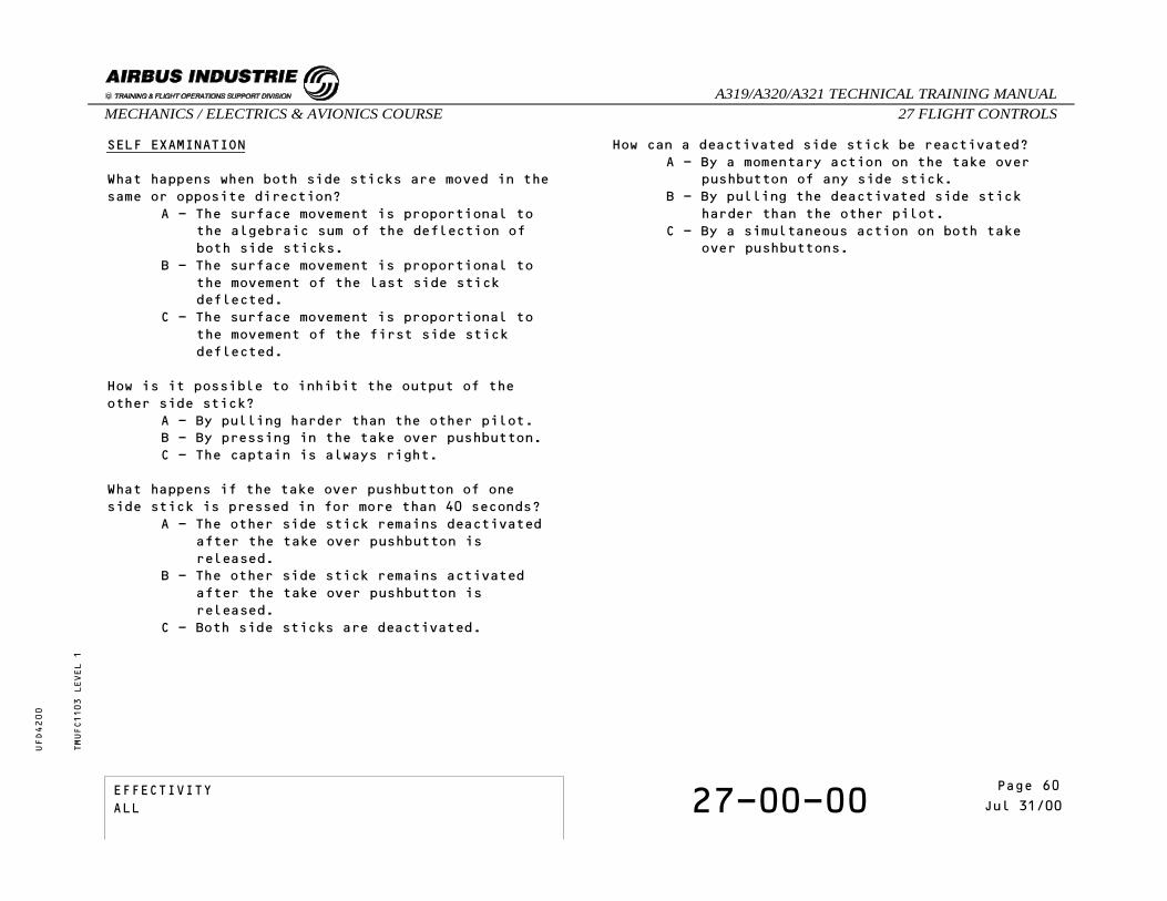
What happens when both side sticks are moved in thesame or opposite direction?
A - The surface movement is proportional tothe algebraic sum of the deflection ofboth side sticks.
B - The surface movement is proportional tothe movement of the last side stickdeflected.
C - The surface movement is proportional tothe movement of the first side stickdeflected.
How is it possible to inhibit the output of theother side stick?
A - By pulling harder than the other pilot.B - By pressing in the take over pushbutton.C - The captain is always right.
What happens if the take over pushbutton of oneside stick is pressed in for more than 40 seconds?
A - The other side stick remains deactivatedafter the take over pushbutton isreleased.
B - The other side stick remains activatedafter the take over pushbutton isreleased.
C - Both side sticks are deactivated.
How can a deactivated side stick be reactivated?A - By a momentary action on the take over
pushbutton of any side stick.B - By pulling the deactivated side stick
harder than the other pilot.C - By a simultaneous action on both take
over pushbuttons.
TMUFC1103 LEVEL 1
EFFECTIVITY 27-00-00 Page 18Jul 31/00
_A319/A320/A321 TECHNICAL TRAINING MANUAL27 FLIGHT CONTROLSMECHANICS / ELECTRICS & AVIONICS COURSE
UFD4200
Page 60EFFECTIVITYALL

27 - FLIGHT CONTROLS
27-00-00 ECAM PAGE PRESENTATION
CONTENTS:Spoiler / Speed BrakeHydraulic System PressureELAC / SECAileron / Roll SpoilersGround SpoilersElevator PositionPitch Trim PositionRudder Position
TMUFC1202 LEVEL 1
EFFECTIVITY 27-00-00 Page 1Jun 30/97
_A319/A320/A321 TECHNICAL TRAINING MANUAL27 FLIGHT CONTROLSMECHANICS / ELECTRICS & AVIONICS COURSE
UFD4200
Page 61EFFECTIVITYALL

ECAM PAGE PRESENTATION
SPOILER / SPEED BRAKE
Each spoiler and speed brake indication is green whenthe surface is operative and amber when inoperative.
HYDRAULIC SYSTEM PRESSURE
The hydraulic system pressure indication is normallygreen and becomes amber in case of low pressure.
ELAC / SEC
The Elevator Aileron Computer (ELAC) and SpoilerElevator Computer (SEC) reference numbers are normallygreen and become amber in case of failure.
AILERON / ROLL SPOILERS
The aileron position is indicated by a green index ona white scale. They become amber if both actuators are inoperative.
TMUFC1202-T01 LEVEL 1
EFFECTIVITY 27-00-00 Page 2Jun 30/97
_A319/A320/A321 TECHNICAL TRAINING MANUAL27 FLIGHT CONTROLSMECHANICS / ELECTRICS & AVIONICS COURSE
UFD4200
Page 62EFFECTIVITYALL

ECAM PAGE PRESENTATIONTMUFC1202-P01 LEVEL 1
EFFECTIVITY 27-00-00 Page 3Jun 30/97
_A319/A320/A321 TECHNICAL TRAINING MANUAL27 FLIGHT CONTROLSMECHANICS / ELECTRICS & AVIONICS COURSE
UFD4200
Page 63EFFECTIVITYALL

ECAM PAGE PRESENTATION
GROUND SPOILERS
At landing, the WHEEL page appears automatically onthe lower ECAM and shows the ground spoilers status.
TMUFC1202-T02 LEVEL 1
EFFECTIVITY 27-00-00 Page 4Jun 30/97
_A319/A320/A321 TECHNICAL TRAINING MANUAL27 FLIGHT CONTROLSMECHANICS / ELECTRICS & AVIONICS COURSE
UFD4200
Page 64EFFECTIVITYALL

ECAM PAGE PRESENTATIONTMUFC1202-P02 LEVEL 1
EFFECTIVITY 27-00-00 Page 5Jun 30/97
_A319/A320/A321 TECHNICAL TRAINING MANUAL27 FLIGHT CONTROLSMECHANICS / ELECTRICS & AVIONICS COURSE
UFD4200
Page 65EFFECTIVITYALL

ECAM PAGE PRESENTATION
ELEVATOR POSITION
The elevator position is indicated by a green indexon a white scale. They become amber if both actuatorsare inoperative.
PITCH TRIM POSITION
The normally green pitch trim position indicationbecomes amber in case of green and yellow hydraulicsystem low pressure.The PITCH TRIM inscription is normally white. Itbecomes amber in case of Trimmable HorizontalStabilizer jam.
TMUFC1202-T03 LEVEL 1
EFFECTIVITY 27-00-00 Page 6Jun 30/97
_A319/A320/A321 TECHNICAL TRAINING MANUAL27 FLIGHT CONTROLSMECHANICS / ELECTRICS & AVIONICS COURSE
UFD4200
Page 66EFFECTIVITYALL

ECAM PAGE PRESENTATIONTMUFC1202-P03 LEVEL 1
EFFECTIVITY 27-00-00 Page 7Jun 30/97
_A319/A320/A321 TECHNICAL TRAINING MANUAL27 FLIGHT CONTROLSMECHANICS / ELECTRICS & AVIONICS COURSE
UFD4200
Page 67EFFECTIVITYALL

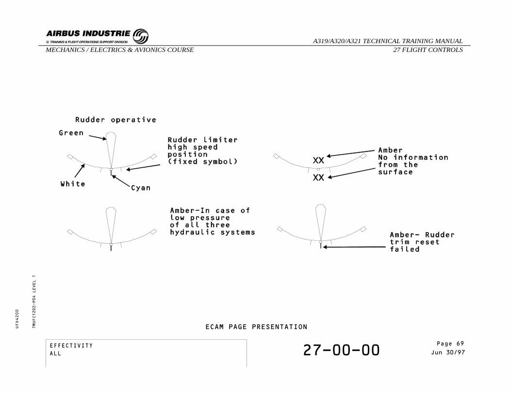
ECAM PAGE PRESENTATION
RUDDER POSITION
The normally green rudder position indication becomesamber in case of low pressure of blue, green and yellowhydraulic systems.
TMUFC1202-T04 LEVEL 1
EFFECTIVITY 27-00-00 Page 8Jun 30/97
_A319/A320/A321 TECHNICAL TRAINING MANUAL27 FLIGHT CONTROLSMECHANICS / ELECTRICS & AVIONICS COURSE
UFD4200
Page 68EFFECTIVITYALL
ECAM PAGE PRESENTATIONTMUFC1202-P04 LEVEL 1
EFFECTIVITY 27-00-00 Page 9Jun 30/97
_A319/A320/A321 TECHNICAL TRAINING MANUAL27 FLIGHT CONTROLSMECHANICS / ELECTRICS & AVIONICS COURSE
UFD4200
Page 69EFFECTIVITYALL
THIS PAGE INTENTIONALLY LEFT BLANK
TMUFC1202 LEVEL 1
EFFECTIVITY 27-00-00 Page 10Jun 30/97
_A319/A320/A321 TECHNICAL TRAINING MANUAL27 FLIGHT CONTROLSMECHANICS / ELECTRICS & AVIONICS COURSE
UFD4200
Page 70EFFECTIVITYALL
27 - FLIGHT CONTROLS
27-00-00 PITCH CONTROL NORMAL D/O
CONTENTS:Side StickElevator Aileron Computer (ELAC)Spoiler Elevator Computer (SEC)Flight Management Guidance Computer (FMGC)ElevatorsTrimmable Horizontal Stabilizer (THS)Trim WheelsSelf Examination
TMUFCT302 LEVEL 3
EFFECTIVITY 27-00-00 Page 1Mar 31/00
_A319/A320/A321 TECHNICAL TRAINING MANUAL27 FLIGHT CONTROLSMECHANICS / ELECTRICS & AVIONICS COURSE
UFD4200
Page 71EFFECTIVITYALL
PITCH CONTROL NORMAL D/O
SIDE STICK
The side stick sends electrical orders to the ElevatorAileron Computers and Spoiler Elevator Computers.
ELEVATOR AILERON COMPUTER (ELAC)
There are 2 ELACs. ELAC 2 normally controls theelevators and trimmable horizontal stabilizer withELAC 1 as a back-up.In case of ELAC 2 failure, ELAC 1 automatically takesover.
TMUFCT302-T01 LEVEL 3
EFFECTIVITY 27-00-00 Page 2Mar 31/00
_A319/A320/A321 TECHNICAL TRAINING MANUAL27 FLIGHT CONTROLSMECHANICS / ELECTRICS & AVIONICS COURSE
UFD4200
Page 72EFFECTIVITYALL

PITCH CONTROL NORMAL D/OTMUFCT302-P01 LEVEL 3
EFFECTIVITY 27-00-00 Page 3Mar 31/00
_A319/A320/A321 TECHNICAL TRAINING MANUAL27 FLIGHT CONTROLSMECHANICS / ELECTRICS & AVIONICS COURSE
UFD4200
Page 73EFFECTIVITYALL
PITCH CONTROL NORMAL D/O
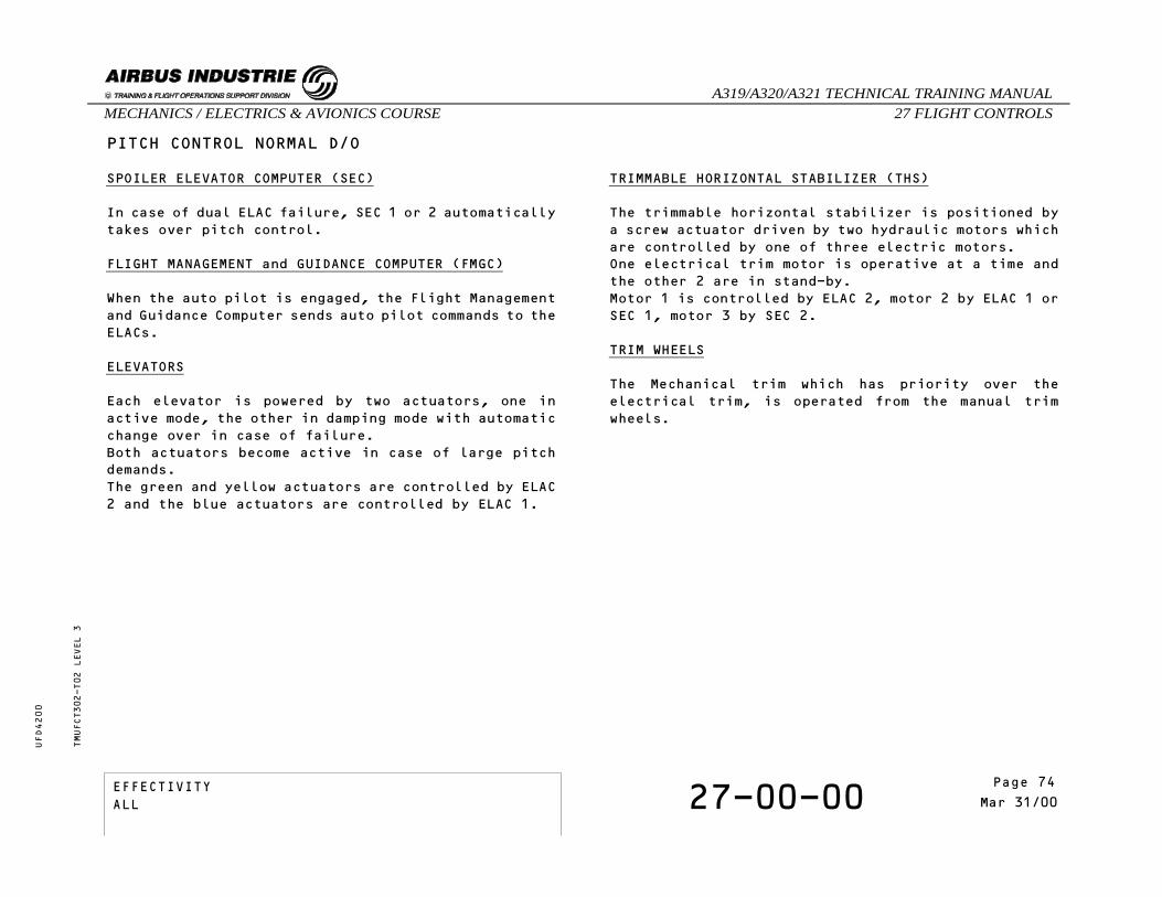
SPOILER ELEVATOR COMPUTER (SEC)
In case of dual ELAC failure, SEC 1 or 2 automaticallytakes over pitch control.
FLIGHT MANAGEMENT and GUIDANCE COMPUTER (FMGC)
When the auto pilot is engaged, the Flight Managementand Guidance Computer sends auto pilot commands to theELACs.
ELEVATORS
Each elevator is powered by two actuators, one inactive mode, the other in damping mode with automaticchange over in case of failure.Both actuators become active in case of large pitchdemands.The green and yellow actuators are controlled by ELAC2 and the blue actuators are controlled by ELAC 1.
TRIMMABLE HORIZONTAL STABILIZER (THS)
The trimmable horizontal stabilizer is positioned bya screw actuator driven by two hydraulic motors whichare controlled by one of three electric motors.One electrical trim motor is operative at a time andthe other 2 are in stand-by.Motor 1 is controlled by ELAC 2, motor 2 by ELAC 1 orSEC 1, motor 3 by SEC 2.
TRIM WHEELS
The Mechanical trim which has priority over theelectrical trim, is operated from the manual trimwheels.
TMUFCT302-T02 LEVEL 3
EFFECTIVITY 27-00-00 Page 4Mar 31/00
_A319/A320/A321 TECHNICAL TRAINING MANUAL27 FLIGHT CONTROLSMECHANICS / ELECTRICS & AVIONICS COURSE
UFD4200
Page 74EFFECTIVITYALL

PITCH CONTROL NORMAL D/O - SPOILER ELEVATOR COMPUTERTMUFCT302-P02 LEVEL 3
EFFECTIVITY 27-00-00 Page 5Mar 31/00
_A319/A320/A321 TECHNICAL TRAINING MANUAL27 FLIGHT CONTROLSMECHANICS / ELECTRICS & AVIONICS COURSE
UFD4200
Page 75EFFECTIVITYALL

SELF EXAMINATION
The Elevator and the THS are normally controlled byELAC 2. What happens if ELAC 2 fails ?
A - Pitch control is automaticallytransferred to ELAC 1.
B - Pitch control is automaticallytransferred to SEC 1 and SEC 2.
C - Pitch control is lost.
TMUFCT302 LEVEL 3
EFFECTIVITY 27-00-00 Page 6Mar 31/00
_A319/A320/A321 TECHNICAL TRAINING MANUAL27 FLIGHT CONTROLSMECHANICS / ELECTRICS & AVIONICS COURSE
UFD4200
Page 76EFFECTIVITYALL
27 - FLIGHT CONTROLS
27-90-00 PITCH CONTROL ABNORMAL D/O
CONTENTS:Alternate Law in Elevator and Aileron Computer (WithProtection)Alternate Law in Elevator and Aileron Computer (WithoutProtection)Alternate Law in Spoiler Elevator ComputerDirect LawMechanical Back-UpPitch Law Reconfigurations
TMUFCT502 LEVEL 3
EFFECTIVITY 27-90-00 Page 1Mar 31/00
_A319/A320/A321 TECHNICAL TRAINING MANUAL27 FLIGHT CONTROLSMECHANICS / ELECTRICS & AVIONICS COURSE
UFD4200
Page 77EFFECTIVITYALL
PITCH CONTROL ABNORMAL D/O
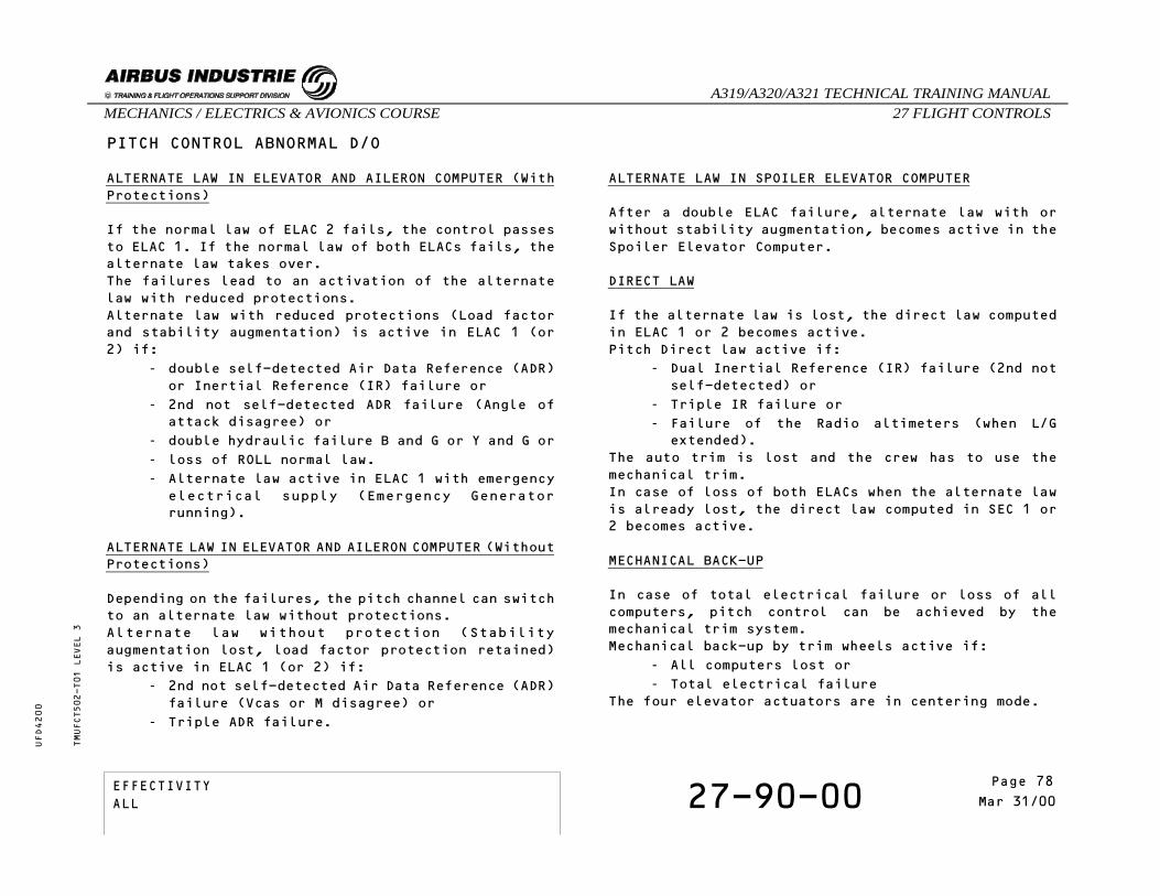
ALTERNATE LAW IN ELEVATOR AND AILERON COMPUTER (WithProtections)
If the normal law of ELAC 2 fails, the control passesto ELAC 1. If the normal law of both ELACs fails, thealternate law takes over.The failures lead to an activation of the alternatelaw with reduced protections.Alternate law with reduced protections (Load factorand stability augmentation) is active in ELAC 1 (or2) if:
- double self-detected Air Data Reference (ADR)or Inertial Reference (IR) failure or
- 2nd not self-detected ADR failure (Angle ofattack disagree) or
- double hydraulic failure B and G or Y and G or- loss of ROLL normal law.- Alternate law active in ELAC 1 with emergencyelectrical supply (Emergency Generatorrunning).
ALTERNATE LAW IN ELEVATOR AND AILERON COMPUTER (WithoutProtections)
Depending on the failures, the pitch channel can switchto an alternate law without protections.Alternate law without protection (Stabilityaugmentation lost, load factor protection retained)is active in ELAC 1 (or 2) if:
- 2nd not self-detected Air Data Reference (ADR)failure (Vcas or M disagree) or
- Triple ADR failure.
ALTERNATE LAW IN SPOILER ELEVATOR COMPUTER
After a double ELAC failure, alternate law with orwithout stability augmentation, becomes active in theSpoiler Elevator Computer.
DIRECT LAW
If the alternate law is lost, the direct law computedin ELAC 1 or 2 becomes active.Pitch Direct law active if:
- Dual Inertial Reference (IR) failure (2nd notself-detected) or
- Triple IR failure or- Failure of the Radio altimeters (when L/Gextended).
The auto trim is lost and the crew has to use themechanical trim.In case of loss of both ELACs when the alternate lawis already lost, the direct law computed in SEC 1 or2 becomes active.
MECHANICAL BACK-UP
In case of total electrical failure or loss of allcomputers, pitch control can be achieved by themechanical trim system.Mechanical back-up by trim wheels active if:
- All computers lost or- Total electrical failure
The four elevator actuators are in centering mode.
TMUFCT502-T01 LEVEL 3
EFFECTIVITY 27-90-00 Page 2Mar 31/00
_A319/A320/A321 TECHNICAL TRAINING MANUAL27 FLIGHT CONTROLSMECHANICS / ELECTRICS & AVIONICS COURSE
UFD4200
Page 78EFFECTIVITYALL

PITCH CONTROL ABNORMAL D/OTMUFCT502-P01 LEVEL 3
EFFECTIVITY 27-90-00 Page 3Mar 31/00
_A319/A320/A321 TECHNICAL TRAINING MANUAL27 FLIGHT CONTROLSMECHANICS / ELECTRICS & AVIONICS COURSE
UFD4200
Page 79EFFECTIVITYALL

PITCH CONTROL ABNORMAL D/O
PITCH LAW RECONFIGURATIONS
This diagram summarises the pitch lawreconfigurations.
TMUFCT502-T02 LEVEL 3
EFFECTIVITY 27-90-00 Page 4Mar 31/00
_A319/A320/A321 TECHNICAL TRAINING MANUAL27 FLIGHT CONTROLSMECHANICS / ELECTRICS & AVIONICS COURSE
UFD4200
Page 80EFFECTIVITYALL

PITCH CONTROL ABNORMAL D/O - PITCH LAW RECONFIGURATIONSTMUFCT502-P02 LEVEL 3
EFFECTIVITY 27-90-00 Page 5Mar 31/00
_A319/A320/A321 TECHNICAL TRAINING MANUAL27 FLIGHT CONTROLSMECHANICS / ELECTRICS & AVIONICS COURSE
UFD4200
Page 81EFFECTIVITYALL

THIS PAGE INTENTIONALLY LEFT BLANK
TMUFCT502 LEVEL 3
EFFECTIVITY 27-90-00 Page 6Mar 31/00
_A319/A320/A321 TECHNICAL TRAINING MANUAL27 FLIGHT CONTROLSMECHANICS / ELECTRICS & AVIONICS COURSE
UFD4200
Page 82EFFECTIVITYALL

27 - FLIGHT CONTROLS
27-34-00 ELEVATOR SERVO CONTROL OPERATION
CONTENTS:Active ModeDamping ModeRe-Centering ModeSelf Examination
TMUFCLK02 LEVEL 3
EFFECTIVITY 27-34-00 Page 1Jul 31/97
_A319/A320/A321 TECHNICAL TRAINING MANUAL27 FLIGHT CONTROLSMECHANICS / ELECTRICS & AVIONICS COURSE
UFD4200
Page 83EFFECTIVITYALL
ELEVATOR SERVO CONTROL OPERATION
ACTIVE MODE
When the elevator servo control is in the active modeit is pressurized and both solenoid valves arede-energized.The servo valve is controlled by one computer at atime.
TMUFCLK02-T01 LEVEL 3
EFFECTIVITY 27-34-00 Page 2Jul 31/97
_A319/A320/A321 TECHNICAL TRAINING MANUAL27 FLIGHT CONTROLSMECHANICS / ELECTRICS & AVIONICS COURSE
UFD4200
Page 84EFFECTIVITYALL

ELEVATOR SERVO CONTROL OPERATION - ACTIVE MODETMUFCLK02-P01 LEVEL 3
EFFECTIVITY 27-34-00 Page 3Jul 31/97
_A319/A320/A321 TECHNICAL TRAINING MANUAL27 FLIGHT CONTROLSMECHANICS / ELECTRICS & AVIONICS COURSE
UFD4200
Page 85EFFECTIVITYALL

ELEVATOR SERVO CONTROL OPERATION
DAMPING MODE
In case of a computer failure, the correspondingsolenoid valve is energized by the other computer andthe elevator servo control is in the damping mode asit is when the actuator is depressurized.
TMUFCLK02-T02 LEVEL 3
EFFECTIVITY 27-34-00 Page 4Jul 31/97
_A319/A320/A321 TECHNICAL TRAINING MANUAL27 FLIGHT CONTROLSMECHANICS / ELECTRICS & AVIONICS COURSE
UFD4200
Page 86EFFECTIVITYALL

ELEVATOR SERVO CONTROL OPERATION - DAMPING MODETMUFCLK02-P02 LEVEL 3
EFFECTIVITY 27-34-00 Page 5Jul 31/97
_A319/A320/A321 TECHNICAL TRAINING MANUAL27 FLIGHT CONTROLSMECHANICS / ELECTRICS & AVIONICS COURSE
UFD4200
Page 87EFFECTIVITYALL

ELEVATOR SERVO CONTROL OPERATION
RE-CENTERING MODE
When the elevator servo control is in the re-centeringmode;It is pressurized, both solenoid valves arede-energized and no command signals are provided tothe Servo valve.Due to the centering device the servo control actuatoris maintained hydraulically in its neutral position.
TMUFCLK02-T03 LEVEL 3
EFFECTIVITY 27-34-00 Page 6Jul 31/97
_A319/A320/A321 TECHNICAL TRAINING MANUAL27 FLIGHT CONTROLSMECHANICS / ELECTRICS & AVIONICS COURSE
UFD4200
Page 88EFFECTIVITYALL

ELEVATOR SERVO CONTROL OPERATION - RE-CENTERING MODETMUFCLK02-P03 LEVEL 3
EFFECTIVITY 27-34-00 Page 7Jul 31/97
_A319/A320/A321 TECHNICAL TRAINING MANUAL27 FLIGHT CONTROLSMECHANICS / ELECTRICS & AVIONICS COURSE
UFD4200
Page 89EFFECTIVITYALL

SELF EXAMINATION
Which mode is adopted by the elevator servo controlwhen both solenoid valves are de-energized, noelectrical command signal is provided and hydraulicpressure is available ?
A - Active.B - Damping.C - Re-centering.
In what mode would the actuator be, with onesolenoid valve energized and pressure available?
A - Active.B - Damping.C - Re-centering.
TMUFCLK02 LEVEL 3
EFFECTIVITY 27-34-00 Page 8Jul 31/97
_A319/A320/A321 TECHNICAL TRAINING MANUAL27 FLIGHT CONTROLSMECHANICS / ELECTRICS & AVIONICS COURSE
UFD4200
Page 90EFFECTIVITYALL
27 - FLIGHT CONTROLS
27-30-00 ELEVATOR COMPONENTS
CONTENTS:Elevator Servo ControlServo Control FilterMode Selector Valve TransducerSolenoid Valves
TMUFCLS02 LEVEL 3
EFFECTIVITY 27-30-00 Page 1Jun 30/96
_A319/A320/A321 TECHNICAL TRAINING MANUAL27 FLIGHT CONTROLSMECHANICS / ELECTRICS & AVIONICS COURSE
UFD4200
Page 91EFFECTIVITYALL

ELEVATOR COMPONENTS
ELEVATOR SERVO CONTROL
IDENTIFICATIONFIN: 34CE1, 34CE4
LOCATIONZONE: 335, 345
SERVO CONTROL FILTER
IDENTIFICATIONFIN:
LOCATIONZONE: 335, 345
MODE SELECTOR VALVE TRANSDUCER
IDENTIFICATIONFIN:
LOCATIONZONE: 335, 345
SOLENOID VALVES
IDENTIFICATIONFIN:
LOCATIONZONE: 335, 345
TMUFCLS02-T01 LEVEL 3
EFFECTIVITY 27-30-00 Page 2Jun 30/96
_A319/A320/A321 TECHNICAL TRAINING MANUAL27 FLIGHT CONTROLSMECHANICS / ELECTRICS & AVIONICS COURSE
UFD4200
Page 92EFFECTIVITYALL

ELEVATOR COMPONENTS - ELEVATOR SERVO CONTROL - SERVO CONTROL FILTER -MODE SELECTOR VALVE TRANSDUCER - SOLENOID VALVES
TMUFCLS02-P01 LEVEL 3
EFFECTIVITY 27-30-00 Page 3Jun 30/96
_A319/A320/A321 TECHNICAL TRAINING MANUAL27 FLIGHT CONTROLSMECHANICS / ELECTRICS & AVIONICS COURSE
UFD4200
Page 93EFFECTIVITYALL

THIS PAGE INTENTIONALLY LEFT BLANK
TMUFCLS02 LEVEL 3
EFFECTIVITY 27-30-00 Page 4Jun 30/96
_A319/A320/A321 TECHNICAL TRAINING MANUAL27 FLIGHT CONTROLSMECHANICS / ELECTRICS & AVIONICS COURSE
UFD4200
Page 94EFFECTIVITYALL
27 - FLIGHT CONTROLS
27-40-00 THS ACTUATOR OPERATION
CONTENTS:Hydraulic MotorsValve BlocksPressure Off BrakesElectrical MotorsPosition TransducersManual ModeElectric ModeJamming ModeSelf examination
TMUFCLM01 LEVEL 3
EFFECTIVITY 27-40-00 Page 1Jan 31/98
_A319/A320/A321 TECHNICAL TRAINING MANUAL27 FLIGHT CONTROLSMECHANICS / ELECTRICS & AVIONICS COURSE
UFD4200
Page 95EFFECTIVITYALL

THS ACTUATOR OPERATION
HYDRAULIC MOTORS
Both hydraulic motors drive the ball screw actuatorthrough a power differential gearbox.It moves up or down a ball nut on which the TrimmableHorizontal Stabilizer (THS) surface is mounted.
VALVE BLOCKS
One valve block is provided for each hydraulic motor.
PRESSURE OF BRAKES
The pressure-off brakes are applied in case ofhydraulic pressure loss.
ELECTRICAL MOTORS
Three electrical motors are provided.Each is driven by the Electrical Flight Control Systemthrough its corresponding computer.Electrical motors are controlled :
- by ELAC 2 for M1,- by ELAC 1 or SEC 1 for M2,- by SEC 2 for M3.
POSITION TRANSDUCERS
Position transducers are installed to feed back theactual position of the override mechanism output andof the ball screw position to the Electrical FlightControl System computer.
MANUAL MODE
The THS actuator can be operated manually from the THStrim hand wheels on the center pedestal in the cockpit.They have priority over the electric trim thanks tothe override mechanism.
ELECTRIC MODE
Normally the THS actuator is operated by one electricaltrim motor through an Electrical Flight Control Systemcomputer.Feedback is given to the THS trim hand wheels in thecockpit.
JAMMING MODE
If one control valve or its driving mechanism is jammedthe hydraulic supply of both hydraulic motors is cutby the shut-off valve control device in each valveblock.Both pressure off brakes are applied. The THS isimmobilized and locked.Reset is possible by depressurization of both hydraulicsystems.
TMUFCLM01-T01 LEVEL 3
EFFECTIVITY 27-40-00 Page 2Jan 31/98
_A319/A320/A321 TECHNICAL TRAINING MANUAL27 FLIGHT CONTROLSMECHANICS / ELECTRICS & AVIONICS COURSE
UFD4200
Page 96EFFECTIVITYALL

TMUFCLM01-P01 LEVEL 3
THS ACTUATOR OPERATION
EFFECTIVITY 27-40-00 Page 3Jan 31/98
_A319/A320/A321 TECHNICAL TRAINING MANUAL27 FLIGHT CONTROLSMECHANICS / ELECTRICS & AVIONICS COURSE
UFD4200
Page 97EFFECTIVITYALL
SELF EXAMINATION
What happens if an electric trim motor fails ?A - THS electric trim is lost.B - THS trims at half speed.C - THS electric trim is fully available.
TMUFCLM01 LEVEL 3
EFFECTIVITY 27-40-00 Page 4Jan 31/98
_A319/A320/A321 TECHNICAL TRAINING MANUAL27 FLIGHT CONTROLSMECHANICS / ELECTRICS & AVIONICS COURSE
UFD4200
Page 98EFFECTIVITYALL
27 - FLIGHT CONTROLS
27-40-00 THS COMPONENTS
CONTENTS:THS ActuatorElectronic Control ModulePitch Trim ActuatorCommand Position TransducerMonitor Position TransducerValve BlockValve Block FilterHydraulic MotorPressure-Off Brakes
TMUFCLU01 LEVEL 3
EFFECTIVITY 27-40-00 Page 1May 31/96
_A319/A320/A321 TECHNICAL TRAINING MANUAL27 FLIGHT CONTROLSMECHANICS / ELECTRICS & AVIONICS COURSE
UFD4200
Page 99EFFECTIVITYALL
THS COMPONENTS
THS ACTUATOR
IDENTIFICATIONFIN: 9CE
LOCATIONZONE: 311
ELECTRONIC CONTROL MODULE
IDENTIFICATIONFIN:
LOCATIONZONE: 311
PITCH TRIM ACTUATOR
IDENTIFICATIONFIN:
LOCATIONZONE: 311
COMMAND POSITION TRANSDUCER
IDENTIFICATIONFIN:
LOCATIONZONE: 311
MONITOR POSITION TRANSDUCER
IDENTIFICATIONFIN:
LOCATIONZONE: 311
TMUFCLU01-T01 LEVEL 3
EFFECTIVITY 27-40-00 Page 2May 31/96
_A319/A320/A321 TECHNICAL TRAINING MANUAL27 FLIGHT CONTROLSMECHANICS / ELECTRICS & AVIONICS COURSE
UFD4200
Page 100EFFECTIVITYALL
TMUFCLU01-P01 LEVEL 3
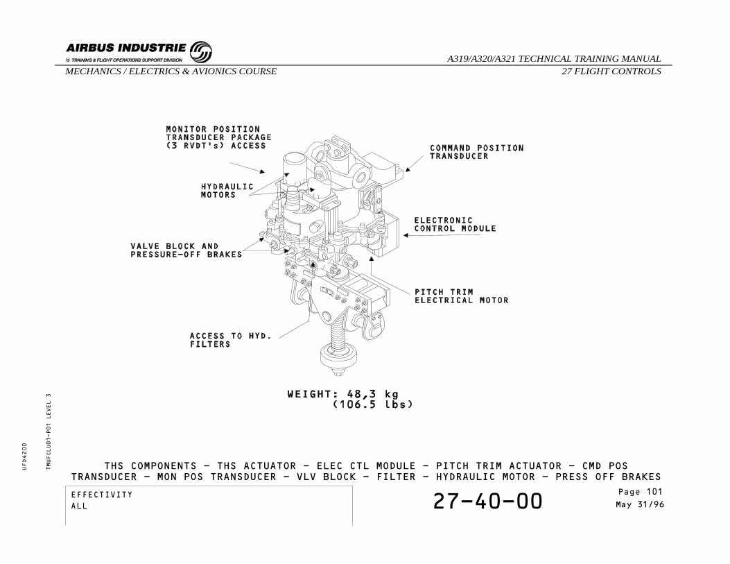
THS COMPONENTS - THS ACTUATOR - ELEC CTL MODULE - PITCH TRIM ACTUATOR - CMD POSTRANSDUCER - MON POS TRANSDUCER - VLV BLOCK - FILTER - HYDRAULIC MOTOR - PRESS OFF BRAKES
EFFECTIVITY 27-40-00 Page 3May 31/96
_A319/A320/A321 TECHNICAL TRAINING MANUAL27 FLIGHT CONTROLSMECHANICS / ELECTRICS & AVIONICS COURSE
UFD4200
Page 101EFFECTIVITYALL

THS COMPONENTS
VALVE BLOCK
IDENTIFICATIONFIN:
LOCATIONZONE: 311, 312
VALVE BLOCK FILTER
IDENTIFICATIONFIN:
LOCATIONZONE: 311, 312
HYDRAULIC MOTOR
IDENTIFICATIONFIN:
LOCATIONZONE: 311, 312
PRESSURE-OFF BRAKES
IDENTIFICATIONFIN:
LOCATIONZONE: 311, 312
TMUFCLU01-T01 LEVEL 3
EFFECTIVITY 27-40-00 Page 4May 31/96
_A319/A320/A321 TECHNICAL TRAINING MANUAL27 FLIGHT CONTROLSMECHANICS / ELECTRICS & AVIONICS COURSE
UFD4200
Page 102EFFECTIVITYALL

27 - FLIGHT CONTROLS
27-00-00 ROLL CONTROL NORMAL D/O
CONTENTS:Side StickElevator Aileron Computer (ELAC)Spoiler Elevator Computer (SEC)Flight Augmentation Computer (FAC)Flight Management and Guidance Computer (FMGC)AileronsSpoilers
TMUFCT602 LEVEL 3
EFFECTIVITY 27-00-00 Page 1Mar 31/00
_A319/A320/A321 TECHNICAL TRAINING MANUAL27 FLIGHT CONTROLSMECHANICS / ELECTRICS & AVIONICS COURSE
UFD4200
Page 103EFFECTIVITYALL

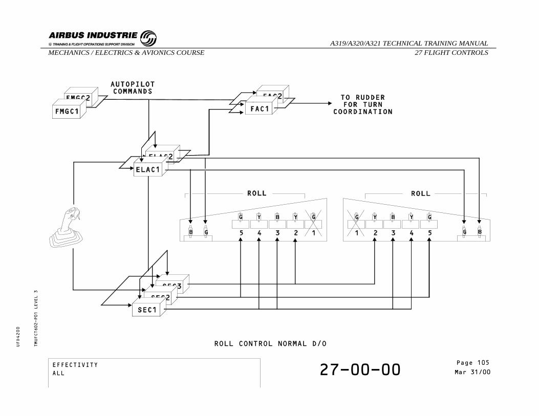
ROLL CONTROL NORMAL D/O
SIDE STICK
The Side stick sends electrical orders to the ElevatorAileron Computers (ELACs) and Spoiler ElevatorComputers (SECs).
ELAC
There are two ELACs: ELAC 1 normally controls theailerons, with ELAC 2 as back-up.In case of failure of ELAC 1, ELAC 2 will automaticallytake control.
SEC
Using orders coming from the ELACs, each SEC sendsorders to one or two pairs of spoilers, withoutback-up.
FAC
Flight Augmentation Computer 1 (FAC 1), with FAC 2 asback-up, transmits turn coordination orders for therudder.
FMGC
When the autopilot is engaged, the Flight Managementand Guidance Computer (FMGC) sends roll commands tothe ELACs and the FACs, and to the SECs through theELACs.
AILERONS
There are two electrically controlled hydraulicactuators per aileron, one in active mode, the otherin damping mode.The left Blue and right Green actuators are controlledby ELAC 1 and the two other actuators by ELAC 2.All aileron actuators revert to damping mode in caseof a double ELAC failure or Green and Blue hydrauliclow pressure.
SPOILERS
Each spoiler is powered by one hydraulic actuator.Surfaces are automatically retracted if a fault isdetected by the monitoring system or if there is noelectrical supply.In case of loss of hydraulic power supply:
- if retracted, the surface remains retracted,- if not retracted, the surface will maintainexisting deflection or less if pushed downby aerodynamic forces (to the zero hingemoment position).
TMUFCT602-T01 LEVEL 3
EFFECTIVITY 27-00-00 Page 2Mar 31/00
_A319/A320/A321 TECHNICAL TRAINING MANUAL27 FLIGHT CONTROLSMECHANICS / ELECTRICS & AVIONICS COURSE
UFD4200
Page 104EFFECTIVITYALL
ROLL CONTROL NORMAL D/OTMUFCT602-P01 LEVEL 3
EFFECTIVITY 27-00-00 Page 3Mar 31/00
_A319/A320/A321 TECHNICAL TRAINING MANUAL27 FLIGHT CONTROLSMECHANICS / ELECTRICS & AVIONICS COURSE
UFD4200
Page 105EFFECTIVITYALL

THIS PAGE LEFT INTENTIONALLY BLANK
TMUFCT602 LEVEL 3
EFFECTIVITY 27-00-00 Page 4Mar 31/00
_A319/A320/A321 TECHNICAL TRAINING MANUAL27 FLIGHT CONTROLSMECHANICS / ELECTRICS & AVIONICS COURSE
UFD4200
Page 106EFFECTIVITYALL

27 - FLIGHT CONTROLS
27-00-00 ROLL CONTROL ABNORMAL D/O
CONTENTSComputer FailuresServo Control FailuresElectrical FailureSelf Examination
TMUFCT702 LEVEL 1
EFFECTIVITY 27-00-00 Page 1Mar 31/00
_A319/A320/A321 TECHNICAL TRAINING MANUAL27 FLIGHT CONTROLSMECHANICS / ELECTRICS & AVIONICS COURSE
UFD4200
Page 107EFFECTIVITYALL

ROLL CONTROL ABNORMAL D/O
COMPUTER FAILURES
A computer failure can engage a lateral abnormalconfiguration. The loss of Elevator Aileron Computer1 (ELAC 1) leads to select ELAC 2 active.ELAC 2 computes the lateral orders in normal law andtransmits them to the Spoiler Elevator Computers forthe roll spoilers.In case of loss of both ELACs only spoilers areavailable. The SECs control the roll in direct law andthe yaw damping function normal law is lost.
SERVO CONTROL FAILURES
In case of failure of one aileron servo control, thesecond one takes over and is controlled by the otherELAC.ELAC 1 still computes the orders and ELAC 2 is in slavemode. The right green servo control is controlled byELAC 1 and the left green servo control by ELAC 2.In case of failure of both ELAC 1 servo controls, thenELAC 2 does the computation and controls its servocontrols.In case of failure of both servo controls of a sameaileron, the other aileron is still operated.In case of failure of a spoiler servo control, theopposite surface is retracted.
ELECTRICAL FAILURE
In case of total electrical loss, induced roll isobtained by using the rudder pedals which have amechanical control.
TMUFCT702-T01 LEVEL 1
EFFECTIVITY 27-00-00 Page 2Mar 31/00
_A319/A320/A321 TECHNICAL TRAINING MANUAL27 FLIGHT CONTROLSMECHANICS / ELECTRICS & AVIONICS COURSE
UFD4200
Page 108EFFECTIVITYALL

ROLL CONTROL ABNORMAL D/OTMUFCT702-P01 LEVEL 1
EFFECTIVITY 27-00-00 Page 3Mar 31/00
_A319/A320/A321 TECHNICAL TRAINING MANUAL27 FLIGHT CONTROLSMECHANICS / ELECTRICS & AVIONICS COURSE
UFD4200
Page 109EFFECTIVITYALL

SELF EXAMINATION
In case of loss of the green hydraulic pressure,the roll is achieved by:
A - Ailerons and spoilers 2,3,4,5?B - Aierons and spoilers 2,3,4?C - Spoilers 2,3,4 only?
TMUFCT702 LEVEL 1
EFFECTIVITY 27-00-00 Page 4Mar 31/00
_A319/A320/A321 TECHNICAL TRAINING MANUAL27 FLIGHT CONTROLSMECHANICS / ELECTRICS & AVIONICS COURSE
UFD4200
Page 110EFFECTIVITYALL

27 - FLIGHT CONTROLS
27-00-00 YAW CONTROL NORMAL D/O
CONTENTS:GeneralRudder PedalsElevator Aileron ComputerFlight Augmentation ComputerFlight Management and Guidance ComputerRudderRudder TrimRudder LimitationYaw DampingSelf Examination
TMUFCT802 LEVEL 3
EFFECTIVITY 27-00-00 Page 1Mar 30/00
_A319/A320/A321 TECHNICAL TRAINING MANUAL27 FLIGHT CONTROLSMECHANICS / ELECTRICS & AVIONICS COURSE
UFD4200
Page 111EFFECTIVITYALL

YAW CONTROL NORMAL D/O
GENERAL
The yaw control is performed by the rudder, with amaximum deflection of 25° (30° for the A319), and iscontrolled by deflection of the pedals.The rudder is operated by three moving bodyservocontrols with a common mechanical input. Thismechanical input can receive commands from:
- rudder pedal input (mechanical control)- rudder trim actuator (electrical control)- yaw damper input (electrical control)
RUDDER PEDALS
The two pairs of rudder pedals are connected together.They are linked by a cable loop to the mechanicalsummer unit which in turn is connected to the hydraulicrudder actuators via a differential unit.Mechanical rudder control is always available from therudder pedals.The pedal position signals are sent to the ElevatorAileron Computers (ELACs) by the transducer (XDCR)unit.
ELEVATOR AILERON COMPUTER
In manual flight, the ELACs transmit the yaw damping,turn coordination and rudder trim commands to theFlight Augmentation Computers (FACs).The yaw damping and the turn coordination orders donot move the rudder pedals (no feedback).
FLIGHT AUGMENTATION COMPUTER
The two FACs control the yaw damper servo controls,the rudder trim and the rudder travel limitation unit.FAC 1 has priority. FAC 2 is in hot stand-by.
FLIGHT MANAGEMENT AND GUIDANCE COMPUTER
When the autopilot is engaged, the Flight Managementand Guidance Computers (FMGCs) send commands to theFACs for rudder trimming, yaw control and yaw dampingfunction.
RUDDER
The rudder is powered by three hydraulic actuatorsoperating in parallel.
RUDDER TRIM
The rudder trim is achieved by two electric motors,each controlled by its associated FAC.In manual flight:
- The pilot can apply rudder trim at 1°/sec fromthe RUD TRIM rotary switch.
In automatic flight:- The asymmetry compensation function isavailable in case of lateral asymmetry.
- The yaw automatic trim is active for lateralasymmetry and engine failure compensation at5°/sec.
Trimming causes rudder pedal movement.
TMUFCT802-T01 LEVEL 3
EFFECTIVITY 27-00-00 Page 2Mar 30/00
_A319/A320/A321 TECHNICAL TRAINING MANUAL27 FLIGHT CONTROLSMECHANICS / ELECTRICS & AVIONICS COURSE
UFD4200
Page 112EFFECTIVITYALL

YAW CONTROL NORMAL D/OTMUFCT802-P01 LEVEL 3
EFFECTIVITY 27-00-00 Page 3Mar 30/00
_A319/A320/A321 TECHNICAL TRAINING MANUAL27 FLIGHT CONTROLSMECHANICS / ELECTRICS & AVIONICS COURSE
UFD4200
Page 113EFFECTIVITYALL
YAW CONTROL NORMAL D/O
RUDDER LIMITATION
Rudder deflection limiting is achieved by a variablestop unit driven by two electric motors. Each motoris controlled by its associated FAC.The rudder deflection becomes limited as speed isincreased.
YAW DAMPING
The two yaw dampers servo controls are connected tothe rudder hydraulic actuators through a mechanicaldifferential unit: each servo actuator is controlledby its associated FAC.No feedback to the rudder pedals is provided thanksto the differential unit.
TMUFCT802-T02 LEVEL 3
EFFECTIVITY 27-00-00 Page 4Mar 30/00
_A319/A320/A321 TECHNICAL TRAINING MANUAL27 FLIGHT CONTROLSMECHANICS / ELECTRICS & AVIONICS COURSE
UFD4200
Page 114EFFECTIVITYALL

SELF EXAMINATION
How many hydraulic systems power the rudder ? A - One.B - Two.C - Three.
Which signals cause rudder pedal movements ? A - Yaw damping signals.B - Rudder trim signals.C - Turn coordination signals.
TMUFCT802 LEVEL 3
EFFECTIVITY 27-00-00 Page 5Mar 30/00
_A319/A320/A321 TECHNICAL TRAINING MANUAL27 FLIGHT CONTROLSMECHANICS / ELECTRICS & AVIONICS COURSE
UFD4200
Page 115EFFECTIVITYALL

THIS PAGE INTENTIONALLY LEFT BLANK
TMUFCT802 LEVEL 3
EFFECTIVITY 27-00-00 Page 6Mar 30/00
_A319/A320/A321 TECHNICAL TRAINING MANUAL27 FLIGHT CONTROLSMECHANICS / ELECTRICS & AVIONICS COURSE
UFD4200
Page 116EFFECTIVITYALL

27 - FLIGHT CONTROLS
27-00-00 YAW CONTROL ABNORMAL D/O
CONTENTS:Alternate LawYaw Mechanical
TMUFCT902 LEVEL 3
EFFECTIVITY 27-00-00 Page 1Mar 31/00
_A319/A320/A321 TECHNICAL TRAINING MANUAL27 FLIGHT CONTROLSMECHANICS / ELECTRICS & AVIONICS COURSE
UFD4200
Page 117EFFECTIVITYALL

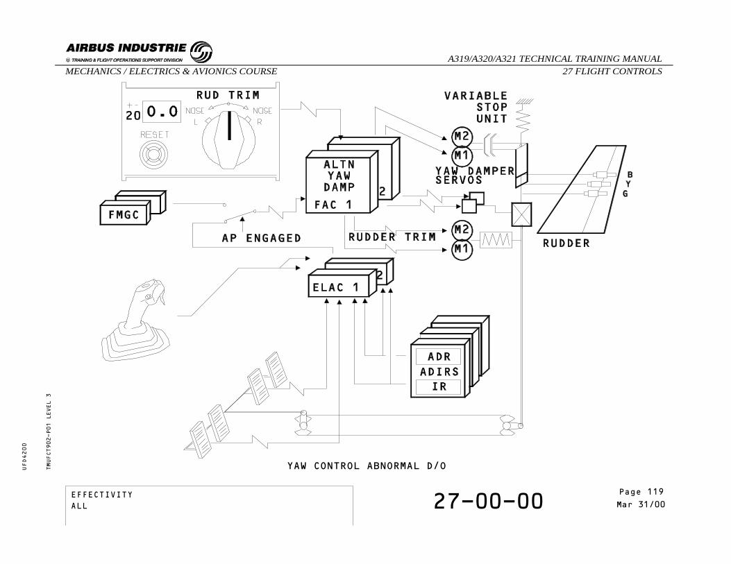
YAW CONTROL ABNORMAL D/O
ALTERNATE LAW
The alternate yaw damper law computed in the FlightAugmentation Computer becomes active if the roll normallaw fails. Turn coordination is no longer available.The alternate yaw damper law also becomes active incase:
- 2 ADRs or 2 IRs or 2 ELACs or both ailerons orall spoilers fail or B+G hydraulic low pressureor loss of pitch normal law.
- The alternate law in FAC 1 is active with theemergency electrical supply (Emergencygenerator running).
- The yaw damper authority is limited to +/- 5o
rudder deflection.
YAW MECHANICAL
The mechanical rudder control, which is available atall times, must be used following the failures shownbelow:
- 2 FACs or 3 ADRs or 3 IRs or G+Y hydraulic lowpressure or electrical power on batteries only.
NOTE: In case of a dual FAC failure, a specific channelin each FAC selects the rudder limit low speedconfiguration when the slats are extended.
TMUFCT902-T01 LEVEL 3
EFFECTIVITY 27-00-00 Page 2Mar 31/00
_A319/A320/A321 TECHNICAL TRAINING MANUAL27 FLIGHT CONTROLSMECHANICS / ELECTRICS & AVIONICS COURSE
UFD4200
Page 118EFFECTIVITYALL
YAW CONTROL ABNORMAL D/OTMUFCT902-P01 LEVEL 3
EFFECTIVITY 27-00-00 Page 3Mar 31/00
_A319/A320/A321 TECHNICAL TRAINING MANUAL27 FLIGHT CONTROLSMECHANICS / ELECTRICS & AVIONICS COURSE
UFD4200
Page 119EFFECTIVITYALL
THIS PAGE INTENTIONALLY LEFT BLANK
TMUFCT902 LEVEL 3
EFFECTIVITY 27-00-00 Page 4Mar 31/00
_A319/A320/A321 TECHNICAL TRAINING MANUAL27 FLIGHT CONTROLSMECHANICS / ELECTRICS & AVIONICS COURSE
UFD4200
Page 120EFFECTIVITYALL

27 - FLIGHT CONTROLS
27-14-00 AILERON SERVO CONTROL OPERATION
CONTENTS:Active ModeDamping ModeSelf Examination
TMUFCLI01 LEVEL 3
EFFECTIVITY 27-14-00 Page 1Oct 31/96
_A319/A320/A321 TECHNICAL TRAINING MANUAL27 FLIGHT CONTROLSMECHANICS / ELECTRICS & AVIONICS COURSE
UFD4200
Page 121EFFECTIVITYALL

AILERON SERVO CONTROL OPERATION
ACTIVE MODE
In the active mode, the aileron servo-control actuatoris pressurized and the solenoid valve energized by thecomputer.
TMUFCLI01-T01 LEVEL 3
EFFECTIVITY 27-14-00 Page 2Oct 31/96
_A319/A320/A321 TECHNICAL TRAINING MANUAL27 FLIGHT CONTROLSMECHANICS / ELECTRICS & AVIONICS COURSE
UFD4200
Page 122EFFECTIVITYALL

AILERON SERVO CONTROL OPERATION - ACTIVE MODETMUFCLI01-P01 LEVEL 3
EFFECTIVITY 27-14-00 Page 3Oct 31/96
_A319/A320/A321 TECHNICAL TRAINING MANUAL27 FLIGHT CONTROLSMECHANICS / ELECTRICS & AVIONICS COURSE
UFD4200
Page 123EFFECTIVITYALL

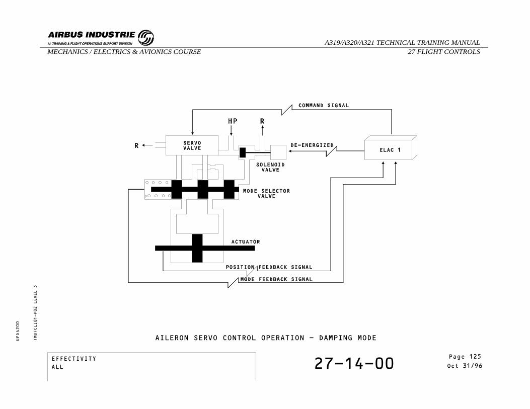
AILERON SERVO CONTROL OPERATION
DAMPING MODE
If the solenoid valve is de-energized or theservo-control actuator is not pressurized, the servocontrol actuator is in damping mode.In damping mode, the actuator follows the controlsurface movements.
TMUFCLI01-T02 LEVEL 3
EFFECTIVITY 27-14-00 Page 4Oct 31/96
_A319/A320/A321 TECHNICAL TRAINING MANUAL27 FLIGHT CONTROLSMECHANICS / ELECTRICS & AVIONICS COURSE
UFD4200
Page 124EFFECTIVITYALL
AILERON SERVO CONTROL OPERATION - DAMPING MODETMUFCLI01-P02 LEVEL 3
EFFECTIVITY 27-14-00 Page 5Oct 31/96
_A319/A320/A321 TECHNICAL TRAINING MANUAL27 FLIGHT CONTROLSMECHANICS / ELECTRICS & AVIONICS COURSE
UFD4200
Page 125EFFECTIVITYALL
SELF EXAMINATION
When is the aileron servo-control actuator indamping mode ?
A - When there is no command signal to theservo valve.
B - Only when the solenoid valve isde-energized.
C - When the solenoid valve is de-energizedor the actuator is not pressurized.
TMUFCLI01 LEVEL 3
EFFECTIVITY 27-14-00 Page 6Oct 31/96
_A319/A320/A321 TECHNICAL TRAINING MANUAL27 FLIGHT CONTROLSMECHANICS / ELECTRICS & AVIONICS COURSE
UFD4200
Page 126EFFECTIVITYALL

27 - FLIGHT CONTROLS
27-14-00 AILERON COMPONENTS
CONTENTS:Aileron Servo ControlHydraulic FilterServo ValveSolenoid ValveMode Selector Valve Transducer
TMUFCLQ01 LEVEL 3
EFFECTIVITY 27-14-00 Page 1Aug 31/97
_A319/A320/A321 TECHNICAL TRAINING MANUAL27 FLIGHT CONTROLSMECHANICS / ELECTRICS & AVIONICS COURSE
UFD4200
Page 127EFFECTIVITYALL

AILERON COMPONENTS
AILERON SERVO CONTROL
IDENTIFICATIONFIN: 33CE1, 33CE2, 33CE3, 33CE4
LOCATIONZONE: 575, 675
COMPONENT DESCRIPTIONIf one Aileron Servo Control is inoperative it mustremain mechanically connected and hydraulicallysupplied for dispatch.
HYDRAULIC FILTER
IDENTIFICATIONFIN:
LOCATIONZONE: 575, 675
SERVO VALVE
IDENTIFICATIONFIN:
LOCATIONZONE: 575, 675
SOLENOID VALVE
IDENTIFICATIONFIN:
LOCATIONZONE: 575, 675
MODE SELECTOR VALVE TRANSDUCER
IDENTIFICATIONFIN:
LOCATIONZONE: 575, 675
TMUFCLQ01-T01 LEVEL 3
EFFECTIVITY 27-14-00 Page 2Aug 31/97
_A319/A320/A321 TECHNICAL TRAINING MANUAL27 FLIGHT CONTROLSMECHANICS / ELECTRICS & AVIONICS COURSE
UFD4200
Page 128EFFECTIVITYALL

AILERON COMPONENTS - AILERON SERVO CONTROL - HYDRAULIC FILTER - SERVO VALVE -SOLENOID VALVE - MODE SELECTOR VALVE TRANSDUCER
TMUFCLQ01-P01 LEVEL 3
EFFECTIVITY 27-14-00 Page 3Aug 31/97
_A319/A320/A321 TECHNICAL TRAINING MANUAL27 FLIGHT CONTROLSMECHANICS / ELECTRICS & AVIONICS COURSE
UFD4200
Page 129EFFECTIVITYALL

THIS PAGE INTENTIONALLY LEFT BLANK
TMUFCLQ01-T01 LEVEL 3
EFFECTIVITY 27-14-00 Page 4Aug 31/97
_A319/A320/A321 TECHNICAL TRAINING MANUAL27 FLIGHT CONTROLSMECHANICS / ELECTRICS & AVIONICS COURSE
UFD4200
Page 130EFFECTIVITYALL
27 - FLIGHT CONTROLS
27-64-00 SPOILER SERVO CONTROL OPERATION
CONTENTS:Active ModeBiased ModeLocked ModeManual ModeSelf Examination
TMUFCLJ02 LEVEL 3
EFFECTIVITY 27-64-00 Page 1Oct 31/98
_A319/A320/A321 TECHNICAL TRAINING MANUAL27 FLIGHT CONTROLSMECHANICS / ELECTRICS & AVIONICS COURSE
UFD4200
Page 131EFFECTIVITYALL

SPOILER SERVO CONTROL OPERATION
ACTIVE MODE
In active mode the spoiler servo control actuator ishydraulically supplied.According to the command signal to the servo valve thespoiler surface will extend or retract.
BIASED MODE
The servo-control actuator is pressurized.Due to an electrical failure the command signal islost.The biased servo valve pressurizes the retractionchamber.The spoiler actuator stays pressurized and the spoilerremains retracted.
TMUFCLJ02-T01 LEVEL 3
EFFECTIVITY 27-64-00 Page 2Oct 31/98
_A319/A320/A321 TECHNICAL TRAINING MANUAL27 FLIGHT CONTROLSMECHANICS / ELECTRICS & AVIONICS COURSE
UFD4200
Page 132EFFECTIVITYALL

SPOILER SERVO CONTROL OPERATION - ACTIVE MODE - BIASED MODETMUFCLJ02-P01 LEVEL 3
EFFECTIVITY 27-64-00 Page 3Oct 31/98
_A319/A320/A321 TECHNICAL TRAINING MANUAL27 FLIGHT CONTROLSMECHANICS / ELECTRICS & AVIONICS COURSE
UFD4200
Page 133EFFECTIVITYALL

SPOILER SERVO CONTROL OPERATION
LOCKED MODE
In locked mode, the hydraulic pressure is lost.The closing valve closes the retraction chamber.The surface can only be moved towards the retractedposition, pushed by aerodynamical forces.
TMUFCLJ02-T02 LEVEL 3
EFFECTIVITY 27-64-00 Page 4Oct 31/98
_A319/A320/A321 TECHNICAL TRAINING MANUAL27 FLIGHT CONTROLSMECHANICS / ELECTRICS & AVIONICS COURSE
UFD4200
Page 134EFFECTIVITYALL

SPOILER SERVO CONTROL OPERATION - LOCKED MODETMUFCLJ02-P02 LEVEL 3
EFFECTIVITY 27-64-00 Page 5Oct 31/98
_A319/A320/A321 TECHNICAL TRAINING MANUAL27 FLIGHT CONTROLSMECHANICS / ELECTRICS & AVIONICS COURSE
UFD4200
Page 135EFFECTIVITYALL

SPOILER SERVO CONTROL OPERATION
MANUAL MODE
To be unlocked, the servo control actuator must bedepressurized.The maintenance unlocking device can be engaged thanksto a key equipped with a red flame. This tool can notbe removed when the servo control is in maintenancemode.Once the maintenance unlocking device is engaged thespoiler surface can be raised manually for inspectionpurposes.
TMUFCLJ02-T03 LEVEL 3
EFFECTIVITY 27-64-00 Page 6Oct 31/98
_A319/A320/A321 TECHNICAL TRAINING MANUAL27 FLIGHT CONTROLSMECHANICS / ELECTRICS & AVIONICS COURSE
UFD4200
Page 136EFFECTIVITYALL

SPOILER SERVO CONTROL OPERATION - MANUAL MODETMUFCLJ02-P03 LEVEL 3
EFFECTIVITY 27-64-00 Page 7Oct 31/98
_A319/A320/A321 TECHNICAL TRAINING MANUAL27 FLIGHT CONTROLSMECHANICS / ELECTRICS & AVIONICS COURSE
UFD4200
Page 137EFFECTIVITYALL

SELF EXAMINATION
Following a hydraulic system failure in flight,what does each spoiler do ?
A - It is retracted by the biasedservo-valve.
B - It is retracted by aerodynamical forcesand locked.
C - It is locked and stops in its actualposition.
How can a spoiler be raised on ground ?A - By de pressurizing the hydraulic system
and using the maintenance unlockingdevice.
B - By pressing the SEC p/b on the flightcontrol panel.
C - By using the maintenance unlockingdevice with the actuator pressurized andSEC p/b operated
TMUFCLJ02 LEVEL 3
EFFECTIVITY 27-64-00 Page 8Oct 31/98
_A319/A320/A321 TECHNICAL TRAINING MANUAL27 FLIGHT CONTROLSMECHANICS / ELECTRICS & AVIONICS COURSE
UFD4200
Page 138EFFECTIVITYALL

27 - FLIGHT CONTROLS
27-60-00 SPOILER COMPONENTS
CONTENTS:Spoiler Servo ControlSpoiler Servo Control FilterSpoiler Servo Control Servo Valve
TMUFCLT02 LEVEL 3
EFFECTIVITY 27-60-00 Page 1Aug 31/97
_A319/A320/A321 TECHNICAL TRAINING MANUAL27 FLIGHT CONTROLSMECHANICS / ELECTRICS & AVIONICS COURSE
UFD4200
Page 139EFFECTIVITYALL

SPOILER COMPONENTS
SPOILER SERVO CONTROL
IDENTIFICATIONFIN: 31CE1, 31CE2, 31CE3, 31CE4, 31CE5, 31CE6, 31CE7,31CE8, 31CE9, 31CE10.
LOCATIONZONE: 574, 674, 583, 683, 584, 684, 585, 685.
SPOILER SERVO CONTROL FILTER
IDENTIFICATIONFIN:
LOCATIONZONE: 574, 674, 583, 683, 584, 684, 585, 685.
SPOILER SERVO CONTROL SERVO VALVE
IDENTIFICATIONFIN:
LOCATIONZONE: 574, 674, 583, 683, 584, 684, 585, 685.
TMUFCLT02-T01 LEVEL 3
EFFECTIVITY 27-60-00 Page 2Aug 31/97
_A319/A320/A321 TECHNICAL TRAINING MANUAL27 FLIGHT CONTROLSMECHANICS / ELECTRICS & AVIONICS COURSE
UFD4200
Page 140EFFECTIVITYALL

SPOILER COMPONENTS - SPOILER SERVO CONTROL - SPOILER SERVO CONTROL FILTER - SPOILER SERVOCONTROL SERVO VALVE
TMUFCLT02-P01 LEVEL 3
EFFECTIVITY 27-60-00 Page 3Aug 31/97
_A319/A320/A321 TECHNICAL TRAINING MANUAL27 FLIGHT CONTROLSMECHANICS / ELECTRICS & AVIONICS COURSE
UFD4200
Page 141EFFECTIVITYALL

THIS PAGE INTENTIONALLY LEFT BLANK
TMUFCLT02 LEVEL 3
EFFECTIVITY 27-60-00 Page 4Aug 31/97
_A319/A320/A321 TECHNICAL TRAINING MANUAL27 FLIGHT CONTROLSMECHANICS / ELECTRICS & AVIONICS COURSE
UFD4200
Page 142EFFECTIVITYALL

27 - FLIGHT CONTROLS
27-22-00 RUDDER TRIM ACTUATOR (D/O)
CONTENTS:GeneralControlsDescription/OperationSelf examination
TMUFCAK01 LEVEL 3
EFFECTIVITY 27-22-00 Page 1Jul 31/00
_A319/A320/A321 TECHNICAL TRAINING MANUAL27 FLIGHT CONTROLSMECHANICS / ELECTRICS & AVIONICS COURSE
UFD4200
Page 143EFFECTIVITYALL
RUDDER TRIM ACTUATOR (D/O)
GENERAL
The rudder trim actuator is installed on the ruddersystem, in the tail area and is one of the mechanicalinputs of the rudder servocontrols.The rudder trim actuator enables the zero forceposition of the artificial feel and trim unit to beadjusted.
CONTROLS
The rudder trim actuator is an electromechanical unitwhich converts the electrical input from the FACs(Flight Augmentation Computer) into a rotation of itsoutput shaft.The rudder trim actuator can be controlled either bythe rudder trim control switch located in the centerpedestal of the cockpit, in manual mode, or by theFMGCs (Flight Management & Guidance Computer) in A/Pmode.In both cases orders are sent via the FACs.
DESCRIPTION/OPERATION
The rudder trim actuator has 2 DC motors, installedon the same shaft. Each one is controlled by anindependent electronic module. With only one motoroperating at a time (via FAC1 or 2).The motors, permanently coupled to a reduction gear,drive the output shaft, via a torque limiter. Then theoutput shaft drives 4 RVDTs, transmitting the outputshaft position signal to the FACs.
TMUFCAK01-T01 LEVEL 3
EFFECTIVITY 27-22-00 Page 2Jul 31/00
_A319/A320/A321 TECHNICAL TRAINING MANUAL27 FLIGHT CONTROLSMECHANICS / ELECTRICS & AVIONICS COURSE
UFD4200
Page 144EFFECTIVITYALL
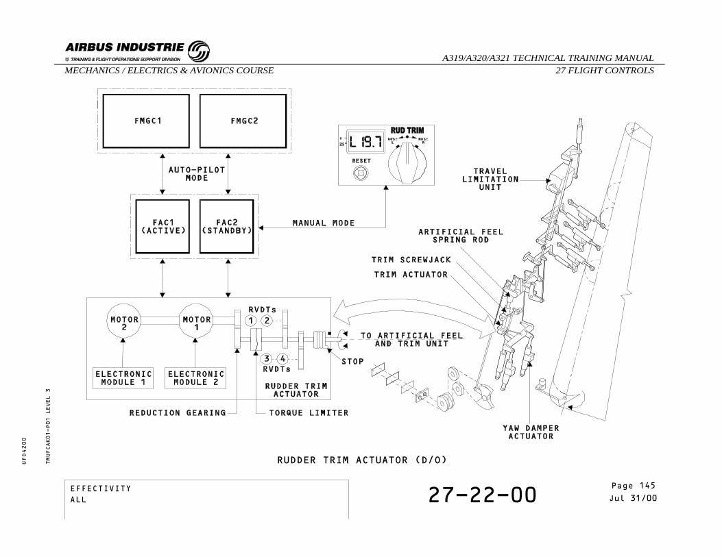
RUDDER TRIM ACTUATOR (D/O)TMUFCAK01-P01 LEVEL 3
EFFECTIVITY 27-22-00 Page 3Jul 31/00
_A319/A320/A321 TECHNICAL TRAINING MANUAL27 FLIGHT CONTROLSMECHANICS / ELECTRICS & AVIONICS COURSE
UFD4200
Page 145EFFECTIVITYALL

SELF EXAMINATION
Which computers control the rudder trim actuator inmanual mode?
A - The FMGCs only.B - The FACs only.C - The FMGCs and the FACs.
TMUFCAK01 LEVEL 3
EFFECTIVITY 27-22-00 Page 4Jul 31/00
_A319/A320/A321 TECHNICAL TRAINING MANUAL27 FLIGHT CONTROLSMECHANICS / ELECTRICS & AVIONICS COURSE
UFD4200
Page 146EFFECTIVITYALL

27 - FLIGHT CONTROLS
27-20-00 RUDDER SERVO CONTROL OPERATION
CONTENTS:Active ModeDamping ModeJammed Control ValveSelf Examination
TMUFCLL01 LEVEL 3
EFFECTIVITY 27-20-00 Page 1Oct 31/97
_A319/A320/A321 TECHNICAL TRAINING MANUAL27 FLIGHT CONTROLSMECHANICS / ELECTRICS & AVIONICS COURSE
UFD4200
Page 147EFFECTIVITYALL
RUDDER SERVO CONTROL OPERATION
ACTIVE MODE
When the rudder servo control actuator is in activemode, the actuator moves to the right or to the leftaccording to the control valve position.
TMUFCLL01-T01 LEVEL 3
EFFECTIVITY 27-20-00 Page 2Oct 31/97
_A319/A320/A321 TECHNICAL TRAINING MANUAL27 FLIGHT CONTROLSMECHANICS / ELECTRICS & AVIONICS COURSE
UFD4200
Page 148EFFECTIVITYALL
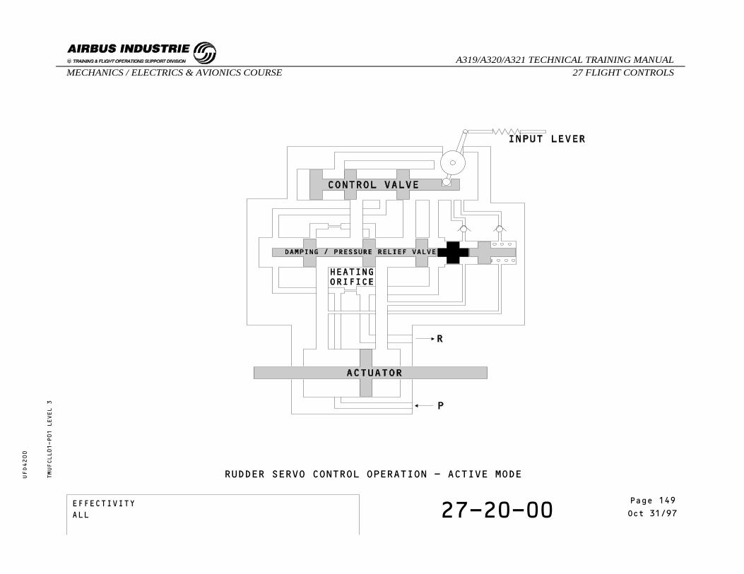
RUDDER SERVO CONTROL OPERATION - ACTIVE MODETMUFCLL01-P01 LEVEL 3
EFFECTIVITY 27-20-00 Page 3Oct 31/97
_A319/A320/A321 TECHNICAL TRAINING MANUAL27 FLIGHT CONTROLSMECHANICS / ELECTRICS & AVIONICS COURSE
UFD4200
Page 149EFFECTIVITYALL

DAMPING MODE
The rudder servo control actuator changes to dampingmode, as soon as the hydraulic pressure supply is cut.
TMUFCLL01-T02 LEVEL 3
EFFECTIVITY 27-20-00 Page 4Oct 31/97
_A319/A320/A321 TECHNICAL TRAINING MANUAL27 FLIGHT CONTROLSMECHANICS / ELECTRICS & AVIONICS COURSE
UFD4200
Page 150EFFECTIVITYALL

RUDDER SERVO CONTROL OPERATION - DAMPING MODETMUFCLL01-P02 LEVEL 3
EFFECTIVITY 27-20-00 Page 5Oct 31/97
_A319/A320/A321 TECHNICAL TRAINING MANUAL27 FLIGHT CONTROLSMECHANICS / ELECTRICS & AVIONICS COURSE
UFD4200
Page 151EFFECTIVITYALL

JAMMED CONTROL VALVE
If the control valve jams, the rudder servo controlactuator follows the rudder surface movement, ensuredby the other rudder servo controls.
TMUFCLL01-T03 LEVEL 3
EFFECTIVITY 27-20-00 Page 6Oct 31/97
_A319/A320/A321 TECHNICAL TRAINING MANUAL27 FLIGHT CONTROLSMECHANICS / ELECTRICS & AVIONICS COURSE
UFD4200
Page 152EFFECTIVITYALL
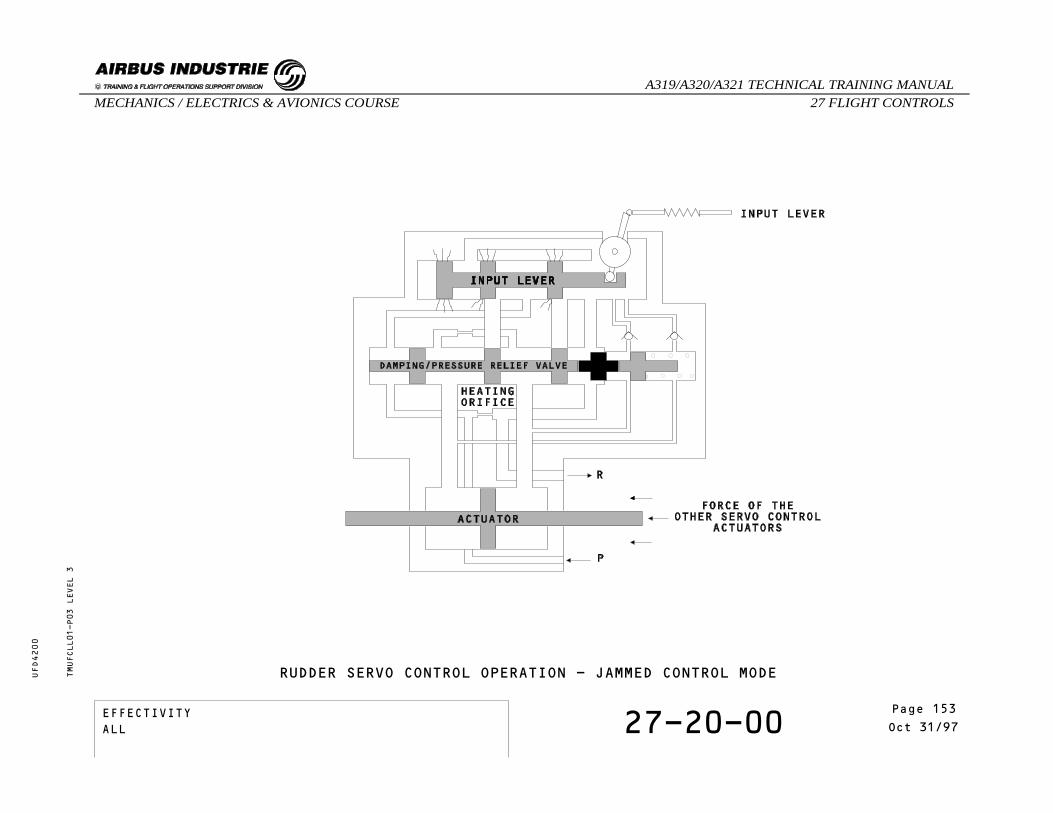
RUDDER SERVO CONTROL OPERATION - JAMMED CONTROL MODETMUFCLL01-P03 LEVEL 3
EFFECTIVITY 27-20-00 Page 7Oct 31/97
_A319/A320/A321 TECHNICAL TRAINING MANUAL27 FLIGHT CONTROLSMECHANICS / ELECTRICS & AVIONICS COURSE
UFD4200
Page 153EFFECTIVITYALL

SELF EXAMINATION
Which modes exist for a rudder servo controlactuator ?
A - A re-centering and active mode.B - A re-centering and damping mode.C - An active and damping mode.
What causes the rudder servo actuator to go todamping mode ?
A - When hydraulic pressure is lost.B - When ELAC 1 signal is lost.C - When Fac 2 and 3 signals are lost.
TMUFCLL01 LEVEL 3
EFFECTIVITY 27-20-00 Page 8Oct 31/97
_A319/A320/A321 TECHNICAL TRAINING MANUAL27 FLIGHT CONTROLSMECHANICS / ELECTRICS & AVIONICS COURSE
UFD4200
Page 154EFFECTIVITYALL

27 - FLIGHT CONTROLS
27-23-00 RUDDER LIMITER OPERATION
CONTENTS:Low Speed ConfigurationVariable LimitationHigh Speed ConfigurationFlight Augmentation Computer FailureSelf examination
TMUFCLO01 LEVEL 3
EFFECTIVITY 27-23-00 Page 1Jun 30/99
_A319/A320/A321 TECHNICAL TRAINING MANUAL27 FLIGHT CONTROLSMECHANICS / ELECTRICS & AVIONICS COURSE
UFD4200
Page 155EFFECTIVITYALL

RUDDER LIMITER OPERATION
LOW SPEED CONFIGURATION
Under 160 Knots the stops are in low speedconfiguration.Full input/output lever movement to the rudder servocontrol is available.
VARIABLE LIMITATION
Between 160 and 380 kts the rudder deflection islimited as a function of a speed.The corresponding law is computed by the FlightAugmentation Computers (FACs).
HIGH SPEED CONFIGURATION
Above 380 knots the stops are in high speedconfiguration.Only limited input/output lever movement to the rudderservo control is available.
TMUFCLO01-T01 LEVEL 3
EFFECTIVITY 27-23-00 Page 2Jun 30/99
_A319/A320/A321 TECHNICAL TRAINING MANUAL27 FLIGHT CONTROLSMECHANICS / ELECTRICS & AVIONICS COURSE
UFD4200
Page 156EFFECTIVITYALL
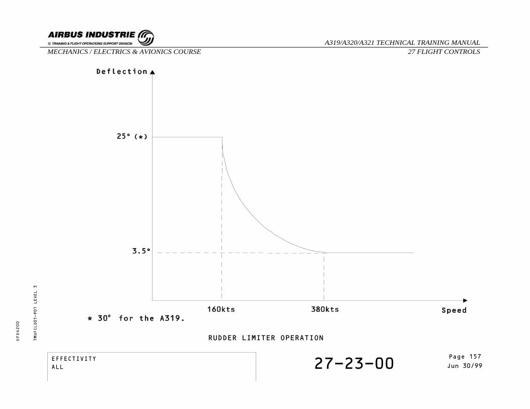
TMUFCLO01-P01 LEVEL 3
RUDDER LIMITER OPERATION
EFFECTIVITY 27-23-00 Page 3Jun 30/99
_A319/A320/A321 TECHNICAL TRAINING MANUAL27 FLIGHT CONTROLSMECHANICS / ELECTRICS & AVIONICS COURSE
UFD4200
Page 157EFFECTIVITYALL

RUDDER LIMITER OPERATION
FLIGHT AUGMENTATION COMPUTER (FAC) FAILURE
If both FACs fail, the rudder travel limitation valueis frozen immediately.In this case, the stops return to the low speedconfiguration when the slats are extended.Thus, the pilot has the full rudder deflectionavailable.
TMUFCLO01-T02 LEVEL 3
EFFECTIVITY 27-23-00 Page 4Jun 30/99
_A319/A320/A321 TECHNICAL TRAINING MANUAL27 FLIGHT CONTROLSMECHANICS / ELECTRICS & AVIONICS COURSE
UFD4200
Page 158EFFECTIVITYALL

RUDDER LIMITER OPERATION - FAC FAILURETMUFCLO01-P02 LEVEL 3
EFFECTIVITY 27-23-00 Page 5Jun 30/99
_A319/A320/A321 TECHNICAL TRAINING MANUAL27 FLIGHT CONTROLSMECHANICS / ELECTRICS & AVIONICS COURSE
UFD4200
Page 159EFFECTIVITYALL
SELF EXAMINATION
What happens if a double FAC failure occurs ?A - The stops stay in high speed
configuration.B - The stops stay where they were at the
moment of the failure.C - The stops return to the low speed
configuration when the slats areextended.
TMUFCLO01 LEVEL 3
EFFECTIVITY 27-23-00 Page 6Jun 30/99
_A319/A320/A321 TECHNICAL TRAINING MANUAL27 FLIGHT CONTROLSMECHANICS / ELECTRICS & AVIONICS COURSE
UFD4200
Page 160EFFECTIVITYALL
27 - FLIGHT CONTROLS
27-26-00 YAW DAMPER SERVO ACTUATOROPERATION
CONTENTS:Active ModeMonitoringBypass Mode (Both SV De-energized)Bypass Mode (One SV De-energized only)Bypass Mode (Hydraulic failure)Self Examination
TMUFCLN01 LEVEL 3
EFFECTIVITY 27-26-00 Page 1Jul 31/00
_A319/A320/A321 TECHNICAL TRAINING MANUAL27 FLIGHT CONTROLSMECHANICS / ELECTRICS & AVIONICS COURSE
UFD4200
Page 161EFFECTIVITYALL

YAW DAMPER SERVO ACTUATOR OPERATION
ACTIVE MODE
The actuator is in active mode when both solenoidvalves are energized and hydraulic pressure servo valveis available. The two selector valves are connectedto the servovalve outputs and allow the servo actuatorto operate in active mode.In this case the pressure switch is not activated.The feedback transducer (LVDT type) provides theservoloop feedback information to the FACs.FAC 1 controls and monitors the green servo actuatorand FAC 2 the yellow one.
MONITORING
A pressure switch fitted to the servo actuator detectsany different position between the selector valves.
TMUFCLN01-T01 LEVEL 3
EFFECTIVITY 27-26-00 Page 2Jul 31/00
_A319/A320/A321 TECHNICAL TRAINING MANUAL27 FLIGHT CONTROLSMECHANICS / ELECTRICS & AVIONICS COURSE
UFD4200
Page 162EFFECTIVITYALL

YAW DAMPER SERVO ACTUATOR OPERATION - ACTIVE MODETMUFCLN01-P01 LEVEL 3
EFFECTIVITY 27-26-00 Page 3Jul 31/00
_A319/A320/A321 TECHNICAL TRAINING MANUAL27 FLIGHT CONTROLSMECHANICS / ELECTRICS & AVIONICS COURSE
UFD4200
Page 163EFFECTIVITYALL

YAW DAMPER SERVO ACTUATOR OPERATION
BYPASS MODE (Both SV De-energized)
The two solenoid valves are de-energized and theassociated selector valves are set to the bypass modeunder the action of their spring. The two pistonchambers are, in this case, interconnected.The pressure switch is not activated.
TMUFCLN01-T02 LEVEL 3
EFFECTIVITY 27-26-00 Page 4Jul 31/00
_A319/A320/A321 TECHNICAL TRAINING MANUAL27 FLIGHT CONTROLSMECHANICS / ELECTRICS & AVIONICS COURSE
UFD4200
Page 164EFFECTIVITYALL

YAW DAMPER SERVO ACTUATOR OPERATION - BYPASS MODE (Both SV De-energized)TMUFCLN01-P02 LEVEL 3
EFFECTIVITY 27-26-00 Page 5Jul 31/00
_A319/A320/A321 TECHNICAL TRAINING MANUAL27 FLIGHT CONTROLSMECHANICS / ELECTRICS & AVIONICS COURSE
UFD4200
Page 165EFFECTIVITYALL

YAW DAMPER SERVO ACTUATOR OPERATION
BYPASS MODE (One SV De-energized only)
In case of a single electrical failure causing oneselector valve to be in bypass mode, the other beingin active mode, the result lies in the interconnectionof the two actuator chambers, thus the actuator is inbypass mode.In this way, thanks to the pressure switch, which isnow connected to the supply pressure, this abnormalconfiguration is indicated to the FACs.
TMUFCLN01-T03 LEVEL 3
EFFECTIVITY 27-26-00 Page 6Jul 31/00
_A319/A320/A321 TECHNICAL TRAINING MANUAL27 FLIGHT CONTROLSMECHANICS / ELECTRICS & AVIONICS COURSE
UFD4200
Page 166EFFECTIVITYALL

YAW DAMPER SERVO ACTUATOR OPERATION - BYPASS MODE (One SV De-energized only)TMUFCLN01-P03 LEVEL 3
EFFECTIVITY 27-26-00 Page 7Jul 31/00
_A319/A320/A321 TECHNICAL TRAINING MANUAL27 FLIGHT CONTROLSMECHANICS / ELECTRICS & AVIONICS COURSE
UFD4200
Page 167EFFECTIVITYALL

YAW DAMPER SERVO ACTUATOR OPERATION
BYPASS MODE (Hydraulic Failure)
With no hydraulic pressure, the two selector valvesare set, under the action of their spring, in bypassmode, thus the two chambers of the piston areinterconnected.In this case, the pressure switch is not activated.
TMUFCLN01-T04 LEVEL 3
EFFECTIVITY 27-26-00 Page 8Jul 31/00
_A319/A320/A321 TECHNICAL TRAINING MANUAL27 FLIGHT CONTROLSMECHANICS / ELECTRICS & AVIONICS COURSE
UFD4200
Page 168EFFECTIVITYALL

YAW DAMPER SERVO ACTUATOR OPERATION - BYPASS MODE (Hydraulic Failure)TMUFCLN01-P04 LEVEL 3
EFFECTIVITY 27-26-00 Page 9Jul 31/00
_A319/A320/A321 TECHNICAL TRAINING MANUAL27 FLIGHT CONTROLSMECHANICS / ELECTRICS & AVIONICS COURSE
UFD4200
Page 169EFFECTIVITYALL
SELF EXAMINATION
Which EFCS computers control and monitor the yawdamper servo actuators ?
A - ELACs and SECs.B - ELACs and SECs and FACs.C - FACs.
In which position is the actuator when bothsolenoids are de-energized ?
A - Re-centering mode.B - Active mode.C - Bypass mode.
TMUFCLN01 LEVEL 3
EFFECTIVITY 27-26-00 Page 10Jul 31/00
_A319/A320/A321 TECHNICAL TRAINING MANUAL27 FLIGHT CONTROLSMECHANICS / ELECTRICS & AVIONICS COURSE
UFD4200
Page 170EFFECTIVITYALL

27 - FLIGHT CONTROLS
27-20-00 RUDDER CHANNEL COMPONENTS (FWD)
CONTENTS:Rack AssemblyRudder Pedal Position TransmitterCable Tension RegulatorRudder Trim Control Switch
TMUFCLW01 LEVEL 3
EFFECTIVITY 27-20-00 Page 1May 31/00
_A319/A320/A321 TECHNICAL TRAINING MANUAL27 FLIGHT CONTROLSMECHANICS / ELECTRICS & AVIONICS COURSE
UFD4200
Page 171EFFECTIVITYALL

RUDDER CHANNEL COMPONENTS (FWD)
RACK ASSEMBLY
IDENTIFICATIONFIN:
LOCATIONZONE:
COMPONENT DESCRIPTIONTwo interconnected pairs of pedals drive the rudder,firstly, through a mechanical linkage located underthe cockpit floor.A lever-controlled rack assembly is used to adjust theposition of the pedals.Then, levers attached to each pedal provide brakinginputs when the pedals turn about their axes.
TMUFCLW01-T01 LEVEL 3
EFFECTIVITY 27-20-00 Page 2May 31/00
_A319/A320/A321 TECHNICAL TRAINING MANUAL27 FLIGHT CONTROLSMECHANICS / ELECTRICS & AVIONICS COURSE
UFD4200
Page 172EFFECTIVITYALL
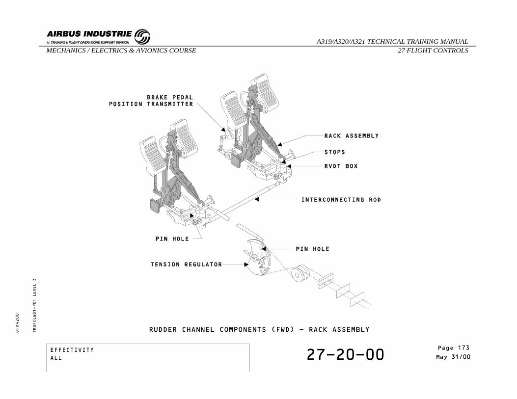
RUDDER CHANNEL COMPONENTS (FWD) - RACK ASSEMBLYTMUFCLW01-P01 LEVEL 3
EFFECTIVITY 27-20-00 Page 3May 31/00
_A319/A320/A321 TECHNICAL TRAINING MANUAL27 FLIGHT CONTROLSMECHANICS / ELECTRICS & AVIONICS COURSE
UFD4200
Page 173EFFECTIVITYALL

RUDDER CHANNEL COMPONENTS (FWD)
RUDDER PEDAL POSITION TRANSMITTER
IDENTIFICATIONFIN: 25CE1, 25CE2
LOCATIONZONE: 121, 122
COMPONENT DESCRIPTIONThe transducer units (RVDTs) send Rudder pedalpositions to the EFCS. Left and right units are not interchangeable.
TMUFCLW01-T02 LEVEL 3
EFFECTIVITY 27-20-00 Page 4May 31/00
_A319/A320/A321 TECHNICAL TRAINING MANUAL27 FLIGHT CONTROLSMECHANICS / ELECTRICS & AVIONICS COURSE
UFD4200
Page 174EFFECTIVITYALL

RUDDER CHANNEL COMPONENTS (FWD) - RUDDER PEDAL POSITION TRANSMITTERTMUFCLW01-P02 LEVEL 3
EFFECTIVITY 27-20-00 Page 5May 31/00
_A319/A320/A321 TECHNICAL TRAINING MANUAL27 FLIGHT CONTROLSMECHANICS / ELECTRICS & AVIONICS COURSE
UFD4200
Page 175EFFECTIVITYALL

RUDDER CHANNEL COMPONENTS (FWD)
CABLE TENSION REGULATOR
IDENTIFICATIONFIN: 103CM
LOCATIONZONE: 125
COMPONENT DESCRIPTIONThe tension regulator maintains a constant tension onthe cable. This absorbs relative variations in lengthdue to thermal expansion, cabin pressurization andstructural deformations.
TMUFCLW01-T03 LEVEL 3
EFFECTIVITY 27-20-00 Page 6May 31/00
_A319/A320/A321 TECHNICAL TRAINING MANUAL27 FLIGHT CONTROLSMECHANICS / ELECTRICS & AVIONICS COURSE
UFD4200
Page 176EFFECTIVITYALL

RUDDER CHANNEL COMPONENTS (FWD) - CABLE TENSION REGULATORTMUFCLW01-P03 LEVEL 3
EFFECTIVITY 27-20-00 Page 7May 31/00
_A319/A320/A321 TECHNICAL TRAINING MANUAL27 FLIGHT CONTROLSMECHANICS / ELECTRICS & AVIONICS COURSE
UFD4200
Page 177EFFECTIVITYALL

RUDDER CHANNEL COMPONENTS (FWD)
RUDDER TRIM CONTROL SWITCH
IDENTIFICATIONFIN: 9CC
LOCATIONZONE: 211PANEL: 110VU
COMPONENT DESCRIPTIONThis is a 3 position rotary switch spring loaded tothe neutral (center) position.The direction of rudder trim travel depends on thedirection of the switch rotation (Left or Right), therudder trim value is indicated on the digitalindicator.The reset p/b switch permits the rudder trim to bereset to zero.
TMUFCLW01-T04 LEVEL 3
EFFECTIVITY 27-20-00 Page 8May 31/00
_A319/A320/A321 TECHNICAL TRAINING MANUAL27 FLIGHT CONTROLSMECHANICS / ELECTRICS & AVIONICS COURSE
UFD4200
Page 178EFFECTIVITYALL

RUDDER CHANNEL COMPONENTS (FWD) - RUDDER TRIM CONTROL SWITCHTMUFCLW01-P04 LEVEL 3
EFFECTIVITY 27-20-00 Page 9May 31/00
_A319/A320/A321 TECHNICAL TRAINING MANUAL27 FLIGHT CONTROLSMECHANICS / ELECTRICS & AVIONICS COURSE
UFD4200
Page 179EFFECTIVITYALL

THIS PAGE INTENTIONALLY LEFT BLANK
TMUFCLW01 LEVEL 3
EFFECTIVITY 27-20-00 Page 10May 31/00
_A319/A320/A321 TECHNICAL TRAINING MANUAL27 FLIGHT CONTROLSMECHANICS / ELECTRICS & AVIONICS COURSE
UFD4200
Page 180EFFECTIVITYALL

27 - FLIGHT CONTROLS
27-20-00 RUDDER CHANNEL COMPONENTS (AFT)
CONTENTS:Rudder Trim ActuatorRudder Artificial Feel and Trim Unit and A/P SolenoidRudder Travel Limitation UnitRudder ServocontrolYaw Damper Servo-ActuatorTransducer UnitsCentering Spring Rods
TMUFCLX01 LEVEL 3
EFFECTIVITY 27-20-00 Page 1May 31/00
_A319/A320/A321 TECHNICAL TRAINING MANUAL27 FLIGHT CONTROLSMECHANICS / ELECTRICS & AVIONICS COURSE
UFD4200
Page 181EFFECTIVITYALL

RUDDER CHANNEL COMPONENTS (AFT)
RUDDER TRIM ACTUATOR
IDENTIFICATIONFIN: 10CC
LOCATIONZONE: 325
COMPONENT DESCRIPTIONThe rudder trim actuator has two independant DC motors(electronic assembly) coupled to a reduction geardriving the output shaft via a torque limiter. The output shaft drives 4 RVDTs.An externally visible index shows the zero positionof the output shaft.The electronic module is an LRU.The output shaft includes a rigging point to get theneutral position.
TMUFCLX01-T01 LEVEL 3
EFFECTIVITY 27-20-00 Page 2May 31/00
_A319/A320/A321 TECHNICAL TRAINING MANUAL27 FLIGHT CONTROLSMECHANICS / ELECTRICS & AVIONICS COURSE
UFD4200
Page 182EFFECTIVITYALL
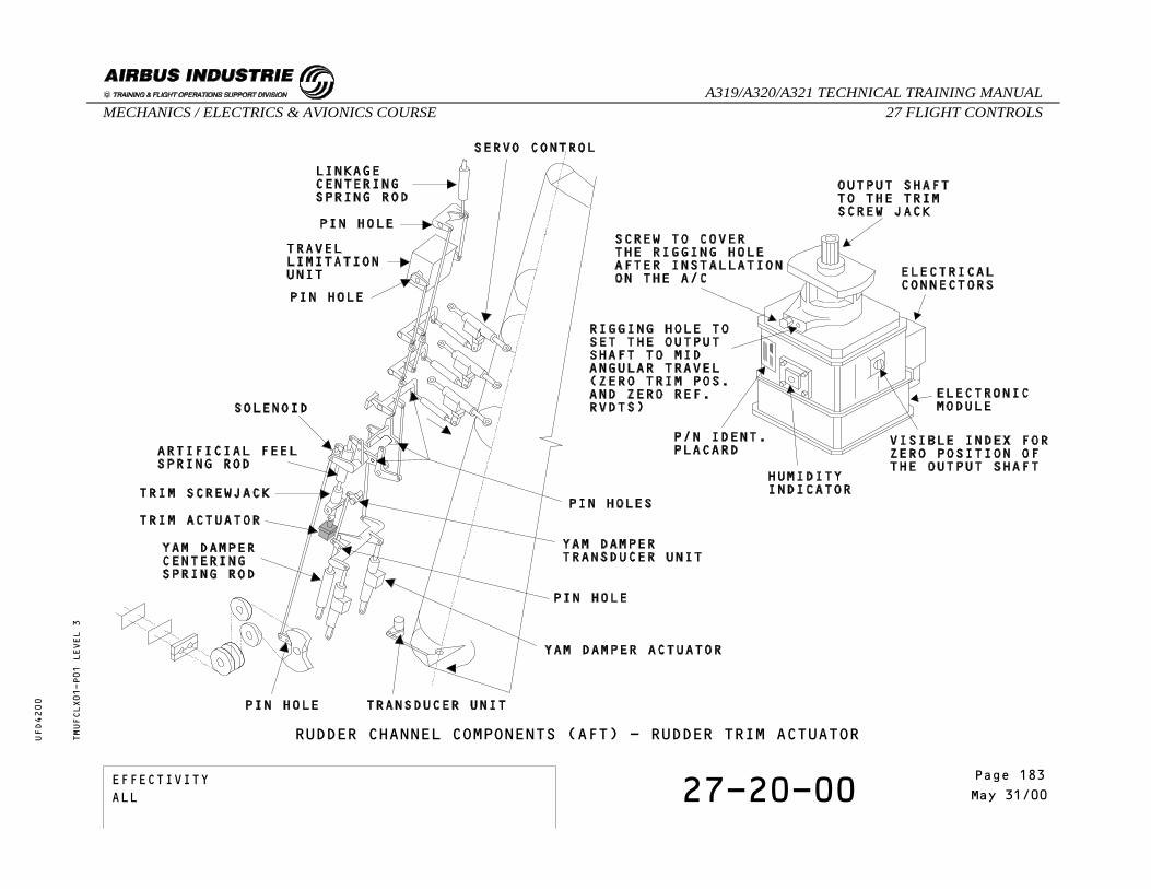
RUDDER CHANNEL COMPONENTS (AFT) - RUDDER TRIM ACTUATORTMUFCLX01-P01 LEVEL 3
EFFECTIVITY 27-20-00 Page 3May 31/00
_A319/A320/A321 TECHNICAL TRAINING MANUAL27 FLIGHT CONTROLSMECHANICS / ELECTRICS & AVIONICS COURSE
UFD4200
Page 183EFFECTIVITYALL

RUDDER CHANNEL COMPONENTS (AFT)
RUDDER ARTIFICIAL FEEL AND TRIM UNIT
LOCATIONZONE: 325
COMPONENT DESCRIPTIONThe artificial feel is engaged in Auto-Pilot mode. Itconsists of a trim screwjack and a constant-resistingload spring-rod that the trim screwjack holds in theneutral position.It comprises a system which can override the Auto-Pilotmode.
AUTO PILOT SOLENOID
IDENTIFICATIONFIN: 16CA
LOCATIONZONE: 325
COMPONENT DESCRIPTIONThis solenoid is controlled by the autopilot to stiffenthe pedals.
TMUFCLX01-T02 LEVEL 3
EFFECTIVITY 27-20-00 Page 4May 31/00
_A319/A320/A321 TECHNICAL TRAINING MANUAL27 FLIGHT CONTROLSMECHANICS / ELECTRICS & AVIONICS COURSE
UFD4200
Page 184EFFECTIVITYALL

RUDDER CHANNEL COMPONENTS (AFT)- ARTIFICIAL FEEL AND TRIM UNIT AND A/P SOLENOIDTMUFCLX01-P02 LEVEL 3
EFFECTIVITY 27-20-00 Page 5May 31/00
_A319/A320/A321 TECHNICAL TRAINING MANUAL27 FLIGHT CONTROLSMECHANICS / ELECTRICS & AVIONICS COURSE
UFD4200
Page 185EFFECTIVITYALL
RUDDER CHANNEL COMPONENTS (AFT)
RUDDER TRAVEL LIMITATION UNIT
IDENTIFICATIONFIN: 4CC
LOCATIONZONE: 325
COMPONENT DESCRIPTIONThe travel limitation unit comprises 2 brushlesselectric motors separately controlled by an electronicassembly. Each motor drives a mechanical device linkedto the input levers. Movement is transmitted to 2 RVDTsand indicate the position of the variable stop.Two rigging pins are used to set the two levers to thezero position.
TMUFCLX01-T03 LEVEL 3
EFFECTIVITY 27-20-00 Page 6May 31/00
_A319/A320/A321 TECHNICAL TRAINING MANUAL27 FLIGHT CONTROLSMECHANICS / ELECTRICS & AVIONICS COURSE
UFD4200
Page 186EFFECTIVITYALL

RUDDER CHANNEL COMPONENTS (AFT) - RUDDER TRAVEL LIMITATION UNITTMUFCLX01-P03 LEVEL 3
EFFECTIVITY 27-20-00 Page 7May 31/00
_A319/A320/A321 TECHNICAL TRAINING MANUAL27 FLIGHT CONTROLSMECHANICS / ELECTRICS & AVIONICS COURSE
UFD4200
Page 187EFFECTIVITYALL

RUDDER CHANNEL COMPONENTS (AFT)
RUDDER SERVOCONTROL
IDENTIFICATIONFIN: 1025GM, 2025GM, 3025GM
LOCATIONZONE: 325
COMPONENT DESCRIPTIONThe rudder is actuated by three identical moving bodyservocontrols (interchangeable) which operatesimultaneously.Each servocontrol is powered by a different hydraulicsystem.
TMUFCLX01-T04 LEVEL 3
EFFECTIVITY 27-20-00 Page 8May 31/00
_A319/A320/A321 TECHNICAL TRAINING MANUAL27 FLIGHT CONTROLSMECHANICS / ELECTRICS & AVIONICS COURSE
UFD4200
Page 188EFFECTIVITYALL

RUDDER CHANNEL COMPONENTS (AFT) - RUDDER SERVOCONTROLTMUFCLX01-P04 LEVEL 3
EFFECTIVITY 27-20-00 Page 9May 31/00
_A319/A320/A321 TECHNICAL TRAINING MANUAL27 FLIGHT CONTROLSMECHANICS / ELECTRICS & AVIONICS COURSE
UFD4200
Page 189EFFECTIVITYALL
RUDDER CHANNEL COMPONENTS (AFT)
YAW DAMPER SERVO-ACTUATOR
IDENTIFICATIONFIN: 3CC1, 3CC2.
LOCATIONZONE: 325
COMPONENT DESCRIPTIONThe two electro-hydraulic servo-actuators areinterchangeable. The following components are LRUs:- filter- solenoid valves- servovalve- pressure switch.No rigging operation is necessary to replace the yawdamper.
TMUFCLX01-T05 LEVEL 3
EFFECTIVITY 27-20-00 Page 10May 31/00
_A319/A320/A321 TECHNICAL TRAINING MANUAL27 FLIGHT CONTROLSMECHANICS / ELECTRICS & AVIONICS COURSE
UFD4200
Page 190EFFECTIVITYALL

RUDDER CHANNEL COMPONENTS (AFT) - YAW DAMPER SERVO-ACTUATORTMUFCLX01-P05 LEVEL 3
EFFECTIVITY 27-20-00 Page 11May 31/00
_A319/A320/A321 TECHNICAL TRAINING MANUAL27 FLIGHT CONTROLSMECHANICS / ELECTRICS & AVIONICS COURSE
UFD4200
Page 191EFFECTIVITYALL

RUDDER CHANNEL COMPONENTS (AFT)
TRANSDUCER UNITS
IDENTIFICATIONFIN: 42WV Rudder 2CC Yaw Damper
LOCATIONZONE: 325
COMPONENT DESCRIPTIONThe rudder transducer unit and the yaw dampertransducer unit consist of a casing in which areinstalled two RVDTs (energized by 26V 400Hz) drivenby an input lever.The rudder transducer unit transmits rudder positioninformation to the EFCS. The other transducer unittransmits yaw damper position monitoring to the FACs.
TMUFCLX01-T06 LEVEL 3
EFFECTIVITY 27-20-00 Page 12May 31/00
_A319/A320/A321 TECHNICAL TRAINING MANUAL27 FLIGHT CONTROLSMECHANICS / ELECTRICS & AVIONICS COURSE
UFD4200
Page 192EFFECTIVITYALL

RUDDER CHANNEL COMPONENTS (AFT) - RUDDER AND YAW DAMPER TRANSDUCER UNITSTMUFCLX01-P06 LEVEL 3
EFFECTIVITY 27-20-00 Page 13May 31/00
_A319/A320/A321 TECHNICAL TRAINING MANUAL27 FLIGHT CONTROLSMECHANICS / ELECTRICS & AVIONICS COURSE
UFD4200
Page 193EFFECTIVITYALL

RUDDER CHANNEL COMPONENTS (AFT)
CENTERING SPRING RODS
IDENTIFICATIONFIN:
LOCATIONZONE: 325
COMPONENT DESCRIPTIONThese centering spring rods must be installed unloaded.The centering spring rods maintain the servocontrolinput levers to a near neutral position, in case ofdisconnection or leakage in the mechanical device.
TMUFCLX01-T07 LEVEL 3
EFFECTIVITY 27-20-00 Page 14May 31/00
_A319/A320/A321 TECHNICAL TRAINING MANUAL27 FLIGHT CONTROLSMECHANICS / ELECTRICS & AVIONICS COURSE
UFD4200
Page 194EFFECTIVITYALL

TMUFCLX01-P07 LEVEL 3
RUDDER CHANNEL COMPONENTS (AFT) - CENTERING SPRING RODS
EFFECTIVITY 27-20-00 Page 15May 31/00
_A319/A320/A321 TECHNICAL TRAINING MANUAL27 FLIGHT CONTROLSMECHANICS / ELECTRICS & AVIONICS COURSE
UFD4200
Page 195EFFECTIVITYALL

THIS PAGE INTENTIONALLY LEFT BLANK
TMUFCLX01 LEVEL 3
EFFECTIVITY 27-20-00 Page 16May 31/00
_A319/A320/A321 TECHNICAL TRAINING MANUAL27 FLIGHT CONTROLSMECHANICS / ELECTRICS & AVIONICS COURSE
UFD4200
Page 196EFFECTIVITYALL
27 - FLIGHT CONTROLS
27-60-00 SPEED BRAKE AND GROUND SPOILERDESCRIPTION AND OPERATION
CONTENTSSpeed Brake FunctionSpeed Brake LogicGround Spoiler FunctionGround Spoiler LogicSelf Examination
TMUFC1405 LEVEL 3
EFFECTIVITY 27-60-00 Page 1Jul 31/00
_A319/A320/A321 TECHNICAL TRAINING MANUAL27 FLIGHT CONTROLSMECHANICS / ELECTRICS & AVIONICS COURSE
UFD4200
Page 197EFFECTIVITYALL

SPEED BRAKE AND GROUND SPOILER DESCRIPTION AND OPERATION
SPEED BRAKE FUNCTION
The Speed Brake Function is commanded in the flightphase following a pilot’s action on the speed brakelever.
The surfaces ensuring this function are spoilers 2thru 4.When one surface is not available on one wing, thesymmetrical one, on the other wing, is inhibited.
The switching to alternate or direct laws does notaffect the Speed Brake Function.
The pitching moment associated to speed brake extensionor retraction is compensated by the pitch control laws.
PRIORITIES : - The roll order has priority over the SpeedBrake Function. When the sum of roll and speed brake commands,relative to one surface, is greater than themaximum possible deflection, the symmetricalsurface is retracted until the differencebetween the two surfaces is equal to the rollorder.
- If the angle of attack protection is activatedwith speed brakes extended, the speed brakesare automatically retracted.
TMUFC1405-T01 LEVEL 3
EFFECTIVITY 27-60-00 Page 2Jul 31/00
_A319/A320/A321 TECHNICAL TRAINING MANUAL27 FLIGHT CONTROLSMECHANICS / ELECTRICS & AVIONICS COURSE
UFD4200
Page 198EFFECTIVITYALL
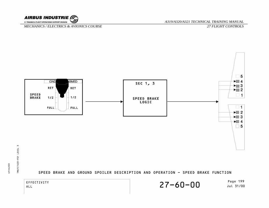
TMUFC1405-P01 LEVEL 3
SPEED BRAKE AND GROUND SPOILER DESCRIPTION AND OPERATION - SPEED BRAKE FUNCTION
EFFECTIVITY 27-60-00 Page 3Jul 31/00
_A319/A320/A321 TECHNICAL TRAINING MANUAL27 FLIGHT CONTROLSMECHANICS / ELECTRICS & AVIONICS COURSE
UFD4200
Page 199EFFECTIVITYALL

SPEED BRAKE AND GROUND SPOILER DESCRIPTION AND OPERATION
SPEED BRAKE LOGIC
Here is the speed brake function logic in detail.
TMUFC1405-T02 LEVEL 3
EFFECTIVITY 27-60-00 Page 4Jul 31/00
_A319/A320/A321 TECHNICAL TRAINING MANUAL27 FLIGHT CONTROLSMECHANICS / ELECTRICS & AVIONICS COURSE
UFD4200
Page 200EFFECTIVITYALL

TMUFC1405-T02 LEVEL 3
SPEED BRAKE AND GROUND SPOILER DESCRIPTION AND OPERATION - SPEED BRAKE LOGIC
EFFECTIVITY 27-60-00 Page 5Jul 31/00
_A319/A320/A321 TECHNICAL TRAINING MANUAL27 FLIGHT CONTROLSMECHANICS / ELECTRICS & AVIONICS COURSE
UFD4200
Page 201EFFECTIVITYALL

SPEED BRAKE AND GROUND SPOILER DESCRIPTION AND OPERATION
GROUND SPOILER FUNCTION
When the logic conditions, which determine the liftdumper extension, are fulfilled, a deflection orderis sent to spoilers 1 to 5, to 10º or 50º extensiondepending on the state of both main landing gear legs(compressed or not).
Ground spoilers are ARMED when the speed brake controllever is pulled up, on manual mode.Moreover, a Pitch Precommand at Ground Spoilerextension/retraction avoids induced pitch effects (innormal or A/P mode).
The Ground Spoiler Function is automatic.
TMUFC1405-T03 LEVEL 3
EFFECTIVITY 27-60-00 Page 6Jul 31/00
_A319/A320/A321 TECHNICAL TRAINING MANUAL27 FLIGHT CONTROLSMECHANICS / ELECTRICS & AVIONICS COURSE
UFD4200
Page 202EFFECTIVITYALL
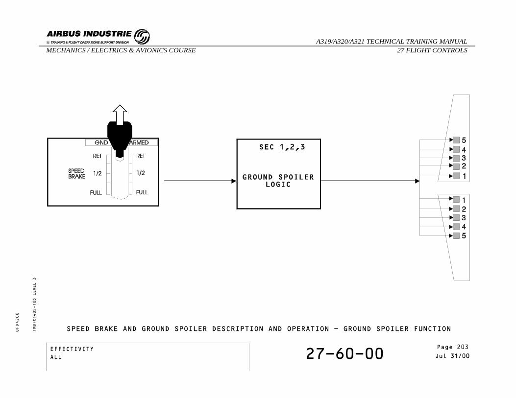
TMUFC1405-T03 LEVEL 3
SPEED BRAKE AND GROUND SPOILER DESCRIPTION AND OPERATION - GROUND SPOILER FUNCTION
EFFECTIVITY 27-60-00 Page 7Jul 31/00
_A319/A320/A321 TECHNICAL TRAINING MANUAL27 FLIGHT CONTROLSMECHANICS / ELECTRICS & AVIONICS COURSE
UFD4200
Page 203EFFECTIVITYALL

SPEED BRAKE AND GROUND SPOILER DESCRIPTION AND OPERATION
GROUND SPOILER LOGIC
Here are the Ground Spoiler function and Partial LiftDamping function logics in detail.
The Partial Lift Dumping function is elaborated in theSECs and activated at reverse selection if only onemain landing gear leg is compressed. Spoilers 1 to 5are partially deflected in order to lower the secondgear leg on to the ground and consequently to activatethe Ground Spoiler function.For normal landing (both MLG legs compressed) thePartial Lift Damping function is masked by the GroundSpoiler function.As soon as both Main Landing Gear legs are compressed,the Ground Spoiler function is activated.
TMUFC1405-T04 LEVEL 3
EFFECTIVITY 27-60-00 Page 8Jul 31/00
_A319/A320/A321 TECHNICAL TRAINING MANUAL27 FLIGHT CONTROLSMECHANICS / ELECTRICS & AVIONICS COURSE
UFD4200
Page 204EFFECTIVITYALL

TMUFC1405-T04 LEVEL 3
SPEED BRAKE AND GROUND SPOILER DESCRIPTION AND OPERATION - GROUND SPOILER LOGIC
EFFECTIVITY 27-60-00 Page 9Jul 31/00
_A319/A320/A321 TECHNICAL TRAINING MANUAL27 FLIGHT CONTROLSMECHANICS / ELECTRICS & AVIONICS COURSE
UFD4200
Page 205EFFECTIVITYALL
SPEED BRAKE AND GROUND SPOILER DESCRIPTION AND OPERATION
SELF EXAMINATION
What happens when the sum of roll and speed brakecommands exceeds the maximum possible deflection ofa spoiler ?
A - The speed brake function is inhibited.B - All spoilers receive an additional
deployment order until one reaches itsmaximum possible deflection.
C - The symmetrical surface is retracteduntil the difference between the twosurfaces is equal to the roll order.
What are the necessary conditions for groundspoiler preselection ?
A - Ground spoilers armed and both throttlesat idle or one throttle at reverse andthe other one at not more than idle.
B - Ground spoilers not armed and boththrottles at idle.
C - Both throttles at idle only.
TMUFC1405 LEVEL 3
EFFECTIVITY 27-60-00 Page 10Jul 31/00
_A319/A320/A321 TECHNICAL TRAINING MANUAL27 FLIGHT CONTROLSMECHANICS / ELECTRICS & AVIONICS COURSE
UFD4200
Page 206EFFECTIVITYALL

27 - FLIGHT CONTROLS
27-00-00 FLIGHT CONTROL WARNINGS
CONTENTS:Elevator Aileron Computer Pitch FaultElevator Aileron Computer FaultAlternate LawAileron Servo FaultAileron FaultStabilizer JamSpoiler FaultSidestick Configuration Fault
TMUFC1502 LEVEL 3
EFFECTIVITY 27-00-00 Page 1Aug 31/97
_A319/A320/A321 TECHNICAL TRAINING MANUAL27 FLIGHT CONTROLSMECHANICS / ELECTRICS & AVIONICS COURSE
UFD4200
Page 207EFFECTIVITYALL

TMUFC1502-P01 LEVEL 3
FLIGHT CONTROL WARNINGS
EFFECTIVITY 27-00-00 Page 2Aug 31/97
_A319/A320/A321 TECHNICAL TRAINING MANUAL27 FLIGHT CONTROLSMECHANICS / ELECTRICS & AVIONICS COURSE
UFD4200
Page 208EFFECTIVITYALL

TMUFC1502-P02 LEVEL 3
FLIGHT CONTROL WARNINGS
EFFECTIVITY 27-00-00 Page 3Aug 31/97
_A319/A320/A321 TECHNICAL TRAINING MANUAL27 FLIGHT CONTROLSMECHANICS / ELECTRICS & AVIONICS COURSE
UFD4200
Page 209EFFECTIVITYALL

THIS PAGE INTENTIONALLY LEFT BLANK
TMUFC1502 LEVEL 3
EFFECTIVITY 27-00-00 Page 4Aug 31/97
_A319/A320/A321 TECHNICAL TRAINING MANUAL27 FLIGHT CONTROLSMECHANICS / ELECTRICS & AVIONICS COURSE
UFD4200
Page 210EFFECTIVITYALL

27 - FLIGHT CONTROLS
27-90-00 EFCS CONTROL INTERFACE
CONTENTS:Pilot OrdersFlight Control PanelsHydraulic PressureRudder Pedal PositionFlight Management Guidance ComputerFlight Augmentation ComputerAir Data Inertial Reference SystemLanding Gear Control and Interface UnitSlat and Flap Control ComputerRadio AltimeterBraking/Steering Control UnitWheel TachometerAccelerometerSelf Examination
TMUFCLG02 LEVEL 3
EFFECTIVITY 27-90-00 Page 1May 31/00
_A319/A320/A321 TECHNICAL TRAINING MANUAL27 FLIGHT CONTROLSMECHANICS / ELECTRICS & AVIONICS COURSE
UFD4200
Page 211EFFECTIVITYALL

EFCS CONTROL INTERFACE
PILOT ORDERS
The pilot orders like side stick, speed brake, groundspoiler or throttle position signals, are transmittedto the ELACs and SECs.According to these inputs and their control laws, thecomputers calculate the elevator, aileron, spoiler,THS and rudder deflection.
TMUFCLG02-T01 LEVEL 3
EFFECTIVITY 27-90-00 Page 2May 31/00
_A319/A320/A321 TECHNICAL TRAINING MANUAL27 FLIGHT CONTROLSMECHANICS / ELECTRICS & AVIONICS COURSE
UFD4200
Page 212EFFECTIVITYALL

EFCS CONTROL INTERFACE - PILOT ORDERSTMUFCLG02-P01 LEVEL 3
EFFECTIVITY 27-90-00 Page 3May 31/00
_A319/A320/A321 TECHNICAL TRAINING MANUAL27 FLIGHT CONTROLSMECHANICS / ELECTRICS & AVIONICS COURSE
UFD4200
Page 213EFFECTIVITYALL

EFCS CONTROL INTERFACE
FLIGHT CONTROL PANELS
Push buttons located on the overhead panels (23VU and24VU) are used to engage/disengage or reset theirrespective computer’s software.
TMUFCLG02-T02 LEVEL 3
EFFECTIVITY 27-90-00 Page 4May 31/00
_A319/A320/A321 TECHNICAL TRAINING MANUAL27 FLIGHT CONTROLSMECHANICS / ELECTRICS & AVIONICS COURSE
UFD4200
Page 214EFFECTIVITYALL

EFCS CONTROL INTERFACE - FLIGHT CONTROL PANELSTMUFCLG02-P02 LEVEL 3
EFFECTIVITY 27-90-00 Page 5May 31/00
_A319/A320/A321 TECHNICAL TRAINING MANUAL27 FLIGHT CONTROLSMECHANICS / ELECTRICS & AVIONICS COURSE
UFD4200
Page 215EFFECTIVITYALL

EFCS CONTROL INTERFACE
HYDRAULIC PRESSURE
The hydraulic pressure status is sent to the ELACs andSECs for activation or deactivation of the relatedservo controls and laws.
TMUFCLG02-T03 LEVEL 3
EFFECTIVITY 27-90-00 Page 6May 31/00
_A319/A320/A321 TECHNICAL TRAINING MANUAL27 FLIGHT CONTROLSMECHANICS / ELECTRICS & AVIONICS COURSE
UFD4200
Page 216EFFECTIVITYALL

TMUFCLG02-P03 LEVEL 3
EFCS CONTROL INTERFACE - HYDRAULIC PRESSURE
EFFECTIVITY 27-90-00 Page 7May 31/00
_A319/A320/A321 TECHNICAL TRAINING MANUAL27 FLIGHT CONTROLSMECHANICS / ELECTRICS & AVIONICS COURSE
UFD4200
Page 217EFFECTIVITYALL

EFCS CONTROL INTERFACE
RUDDER PEDAL POSITION
The rudder pedal position is sent to the ELACs forturn coordination computation, which is then performedthrough the FACs.
TMUFCLG02-T04 LEVEL 3
EFFECTIVITY 27-90-00 Page 8May 31/00
_A319/A320/A321 TECHNICAL TRAINING MANUAL27 FLIGHT CONTROLSMECHANICS / ELECTRICS & AVIONICS COURSE
UFD4200
Page 218EFFECTIVITYALL
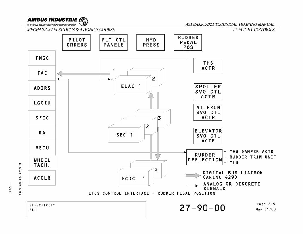
EFCS CONTROL INTERFACE - RUDDER PEDAL POSITIONTMUFCLG02-P04 LEVEL 3
EFFECTIVITY 27-90-00 Page 9May 31/00
_A319/A320/A321 TECHNICAL TRAINING MANUAL27 FLIGHT CONTROLSMECHANICS / ELECTRICS & AVIONICS COURSE
UFD4200
Page 219EFFECTIVITYALL

EFCS CONTROL INTERFACE
FLIGHT MANAGEMENT GUIDANCE COMPUTER (FMGC)
If the auto pilot is active, pitch, roll and yaw orderscomputed by the FMGC are sent to the ELACs and FACs,which control and monitor the surface deflections.
TMUFCLG02-T05 LEVEL 3
EFFECTIVITY 27-90-00 Page 10May 31/00
_A319/A320/A321 TECHNICAL TRAINING MANUAL27 FLIGHT CONTROLSMECHANICS / ELECTRICS & AVIONICS COURSE
UFD4200
Page 220EFFECTIVITYALL

EFCS CONTROL INTERFACE - FMGCTMUFCLG02-P05 LEVEL 3
EFFECTIVITY 27-90-00 Page 11May 31/00
_A319/A320/A321 TECHNICAL TRAINING MANUAL27 FLIGHT CONTROLSMECHANICS / ELECTRICS & AVIONICS COURSE
UFD4200
Page 221EFFECTIVITYALL

EFCS CONTROL INTERFACE
FLIGHT AUGMENTATION COMPUTER (FAC)
The FACs receive rudder deflection informationcomputed either by the ELACs or FMGCs for dutch rolldamping, engine failure compensation and turncoordination.
TMUFCLG02-T06 LEVEL 3
EFFECTIVITY 27-90-00 Page 12May 31/00
_A319/A320/A321 TECHNICAL TRAINING MANUAL27 FLIGHT CONTROLSMECHANICS / ELECTRICS & AVIONICS COURSE
UFD4200
Page 222EFFECTIVITYALL

EFCS CONTROL INTERFACE - FACTMUFCLG02-P06 LEVEL 3
EFFECTIVITY 27-90-00 Page 13May 31/00
_A319/A320/A321 TECHNICAL TRAINING MANUAL27 FLIGHT CONTROLSMECHANICS / ELECTRICS & AVIONICS COURSE
UFD4200
Page 223EFFECTIVITYALL

EFCS CONTROL INTERFACE
AIR DATA INERTIAL REFERENCE SYSTEM (ADIRS)
The ADIRS transmits air data and inertial referencedata to the ELACs and SECs for flight envelopeprotection computation.
TMUFCLG02-T07 LEVEL 3
EFFECTIVITY 27-90-00 Page 14May 31/00
_A319/A320/A321 TECHNICAL TRAINING MANUAL27 FLIGHT CONTROLSMECHANICS / ELECTRICS & AVIONICS COURSE
UFD4200
Page 224EFFECTIVITYALL

EFCS CONTROL INTERFACE - ADIRSTMUFCLG02-P07 LEVEL 3
EFFECTIVITY 27-90-00 Page 15May 31/00
_A319/A320/A321 TECHNICAL TRAINING MANUAL27 FLIGHT CONTROLSMECHANICS / ELECTRICS & AVIONICS COURSE
UFD4200
Page 225EFFECTIVITYALL

EFCS CONTROL INTERFACE
LANDING GEAR CONTROL AND INTERFACE UNIT
The Landing Gear Control Interface Units (LGCIUs)transmit landing gear position information to the ELACsand SECs.
TMUFCLG02-T08 LEVEL 3
EFFECTIVITY 27-90-00 Page 16May 31/00
_A319/A320/A321 TECHNICAL TRAINING MANUAL27 FLIGHT CONTROLSMECHANICS / ELECTRICS & AVIONICS COURSE
UFD4200
Page 226EFFECTIVITYALL
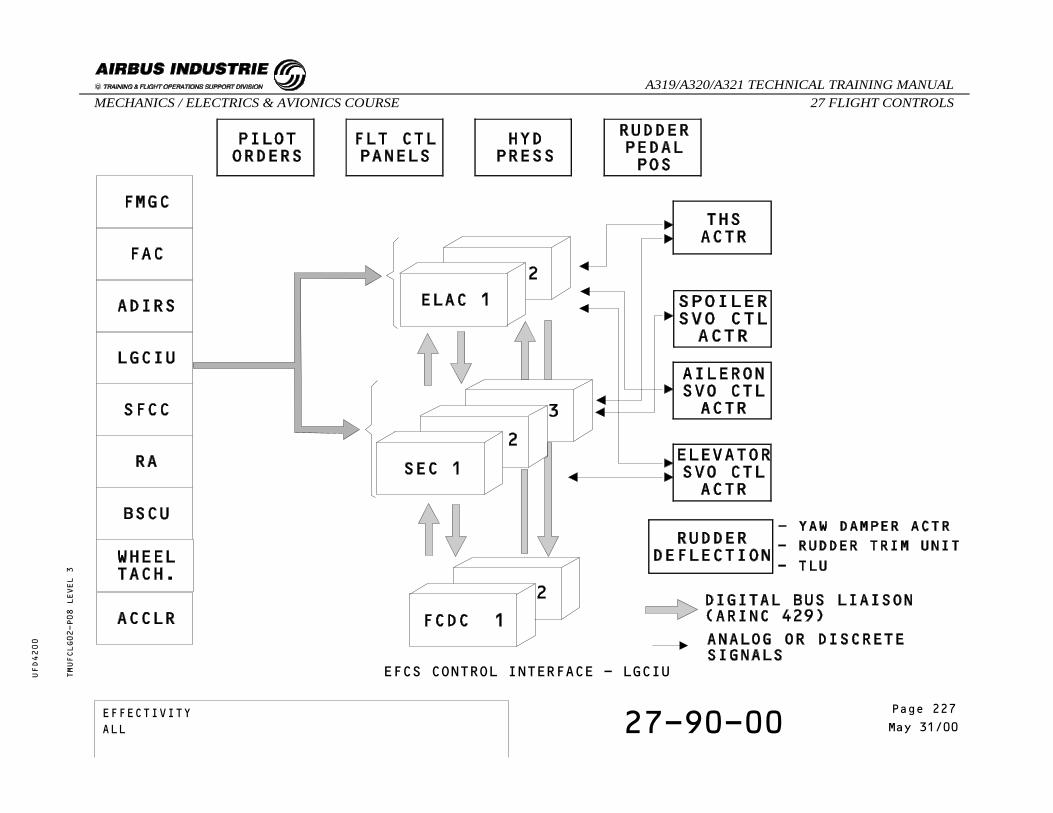
EFCS CONTROL INTERFACE - LGCIUTMUFCLG02-P08 LEVEL 3
EFFECTIVITY 27-90-00 Page 17May 31/00
_A319/A320/A321 TECHNICAL TRAINING MANUAL27 FLIGHT CONTROLSMECHANICS / ELECTRICS & AVIONICS COURSE
UFD4200
Page 227EFFECTIVITYALL

EFCS CONTROL INTERFACE
SLAT AND FLAP CONTROL COMPUTER
The Slat Flap Control Computers (SFCCs) transmit slatflap surface position to the ELACs and SECs for lawcomputation.
TMUFCLG02-T09 LEVEL 3
EFFECTIVITY 27-90-00 Page 18May 31/00
_A319/A320/A321 TECHNICAL TRAINING MANUAL27 FLIGHT CONTROLSMECHANICS / ELECTRICS & AVIONICS COURSE
UFD4200
Page 228EFFECTIVITYALL
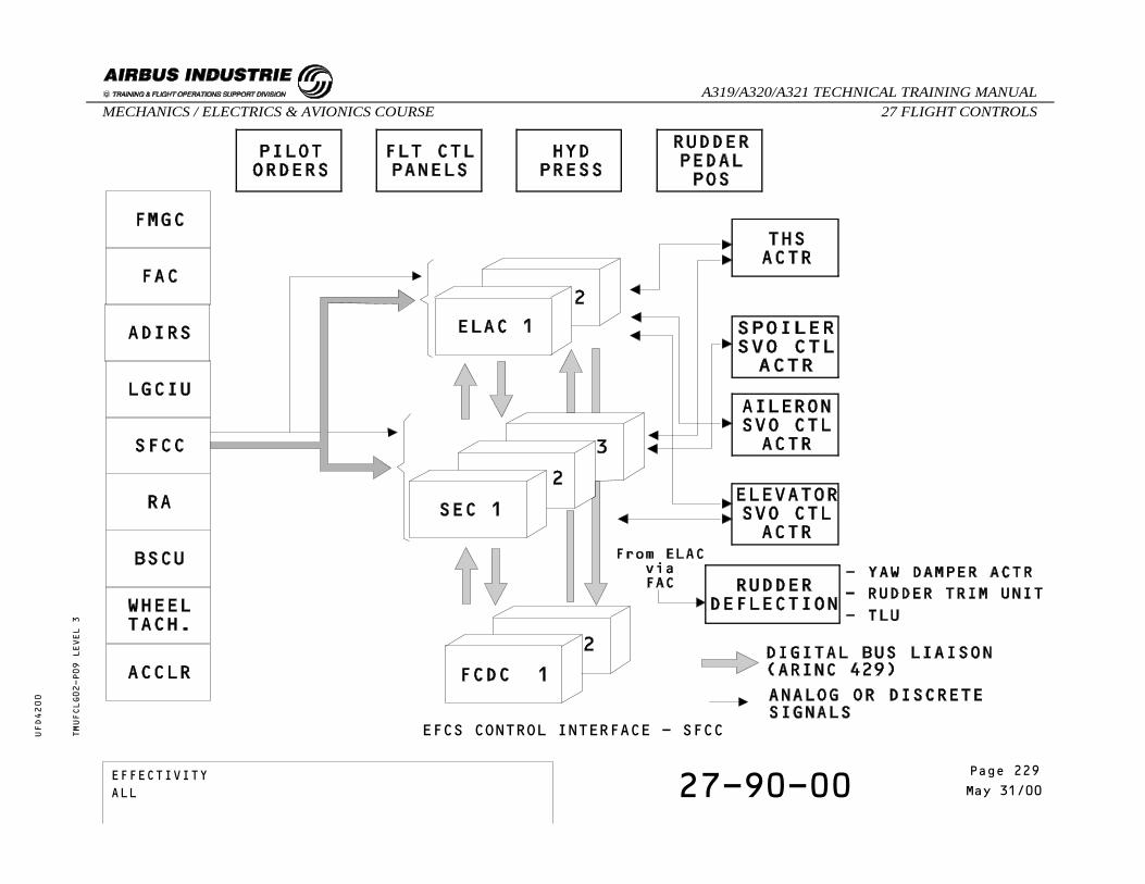
EFCS CONTROL INTERFACE - SFCCTMUFCLG02-P09 LEVEL 3
EFFECTIVITY 27-90-00 Page 19May 31/00
_A319/A320/A321 TECHNICAL TRAINING MANUAL27 FLIGHT CONTROLSMECHANICS / ELECTRICS & AVIONICS COURSE
UFD4200
Page 229EFFECTIVITYALL

EFCS CONTROL INTERFACE
RADIO ALTIMETER
The Radio Altimeter (RA) transmits the altitudeinformation to the ELACs for flare law activation.
TMUFCLG02-T10 LEVEL 3
EFFECTIVITY 27-90-00 Page 20May 31/00
_A319/A320/A321 TECHNICAL TRAINING MANUAL27 FLIGHT CONTROLSMECHANICS / ELECTRICS & AVIONICS COURSE
UFD4200
Page 230EFFECTIVITYALL
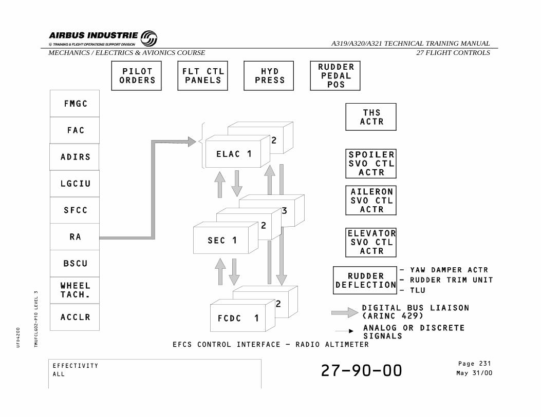
EFCS CONTROL INTERFACE - RADIO ALTIMETERTMUFCLG02-P10 LEVEL 3
EFFECTIVITY 27-90-00 Page 21May 31/00
_A319/A320/A321 TECHNICAL TRAINING MANUAL27 FLIGHT CONTROLSMECHANICS / ELECTRICS & AVIONICS COURSE
UFD4200
Page 231EFFECTIVITYALL
EFCS CONTROL INTERFACE
BRAKING/STEERING CONTROL UNIT
The Braking Steering Control Unit (BSCU) receivesinformation from the ELACs for the nose wheel steeringsystem and from the SECs for the auto brake function.
TMUFCLG02-T11 LEVEL 3
EFFECTIVITY 27-90-00 Page 22May 31/00
_A319/A320/A321 TECHNICAL TRAINING MANUAL27 FLIGHT CONTROLSMECHANICS / ELECTRICS & AVIONICS COURSE
UFD4200
Page 232EFFECTIVITYALL
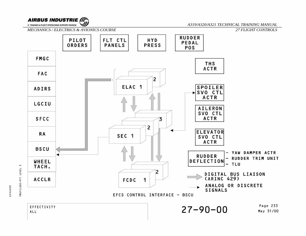
EFCS CONTROL INTERFACE - BSCUTMUFCLG02-P11 LEVEL 3
EFFECTIVITY 27-90-00 Page 23May 31/00
_A319/A320/A321 TECHNICAL TRAINING MANUAL27 FLIGHT CONTROLSMECHANICS / ELECTRICS & AVIONICS COURSE
UFD4200
Page 233EFFECTIVITYALL

EFCS CONTROL INTERFACE
WHEEL TACHOMETER
Each main landing gear wheel speed is transmitted bywheel tachometers to the SECs for ground spoilerextension.
TMUFCLG02-T12 LEVEL 3
EFFECTIVITY 27-90-00 Page 24May 31/00
_A319/A320/A321 TECHNICAL TRAINING MANUAL27 FLIGHT CONTROLSMECHANICS / ELECTRICS & AVIONICS COURSE
UFD4200
Page 234EFFECTIVITYALL

EFCS CONTROL INTERFACE - WHEEL TACHOMETERTMUFCLG02-P12 LEVEL 3
EFFECTIVITY 27-90-00 Page 25May 31/00
_A319/A320/A321 TECHNICAL TRAINING MANUAL27 FLIGHT CONTROLSMECHANICS / ELECTRICS & AVIONICS COURSE
UFD4200
Page 235EFFECTIVITYALL
EFCS CONTROL INTERFACE
ACCELEROMETER
The vertical accelerometers, installed in the FWD cargocompartment, transmit the vertical acceleration of theaircraft to the ELACs and SECs.The vertical accelerometers are also used for thecomputation of Pitch Trim function and Load Factorfunction.
TMUFCLG02-T13 LEVEL 3
EFFECTIVITY 27-90-00 Page 26May 31/00
_A319/A320/A321 TECHNICAL TRAINING MANUAL27 FLIGHT CONTROLSMECHANICS / ELECTRICS & AVIONICS COURSE
UFD4200
Page 236EFFECTIVITYALL

EFCS CONTROL INTERFACE - ACCELEROMETERTMUFCLG02-P13 LEVEL 3
EFFECTIVITY 27-90-00 Page 27May 31/00
_A319/A320/A321 TECHNICAL TRAINING MANUAL27 FLIGHT CONTROLSMECHANICS / ELECTRICS & AVIONICS COURSE
UFD4200
Page 237EFFECTIVITYALL

SELF EXAMINATION
Which computers receive the side stick orders ?A - Only the ELACsB - The ELACs and the SECsC - The FCDCs
For which functions are the vertical accelerometersused ?
A - Load factor functionB - Pitch trim function, computation of the
normal law, yaw damper function and loadfactor function.
C - Pitch trim function, computation of thenormal law and load factor function.
TMUFCLG02 LEVEL 3
EFFECTIVITY 27-90-00 Page 28May 31/00
_A319/A320/A321 TECHNICAL TRAINING MANUAL27 FLIGHT CONTROLSMECHANICS / ELECTRICS & AVIONICS COURSE
UFD4200
Page 238EFFECTIVITYALL

27 -FLIGHT CONTROLS
27-90-00 ELECTRICAL FLIGHT CONTROL SYSTEMMONITOR INTERFACE
CONTENTS:FLIGHT WARNING COMPUTERS/ELECTRONIC CENTRALIZEDAIRCRAFT MONITORINGCENTRALIZED FAULT DISPLAY INTERFACE UNIT/MULTIPURPOSECONTROL AND DISPLAY UNITSelf Examination
TMUFCLH01 LEVEL 3
EFFECTIVITY 27-90-00 Page 1Oct 31/94
_A319/A320/A321 TECHNICAL TRAINING MANUAL27 FLIGHT CONTROLSMECHANICS / ELECTRICS & AVIONICS COURSE
UFD4200
Page 239EFFECTIVITYALL

ELECTRICAL FLIGHT CONTROL SYSTEM MONITOR INTERFACE
FLIGHT WARNING COMPUTERS/ELECTRONIC CENTRALIZEDAIRCRAFT MONITORING
The Flight Control system failures are sent to theFlight Warning Computers (FWCs) by the Flight ControlData Concentrators (FCDCs).The FWCs elaborate the failure messages for displayon the Engine/Warning Display (EWD).The Flight Warning Computers receive Flight Controldata from the Flight Control Data Concentrators forthe indication on the ECAM displays.
CENTRALIZED FAULT DISPLAY INTERFACE UNIT/MULTIPURPOSECONTROL AND DISPLAY UNIT
Data are exchanged between the Flight Control DataConcentrators (FCDCs) and the Centralized FaultDisplay System (CFDS), which enable two communicationmodes, normal mode and interactive mode.Normal mode:
- The FCDCs send the Flight Control systemfailures to the CFDS.
- The CFDS adds general data (time, date, ATAchapter, flight phase, leg) to the failuremessage in order to be displayed on the MCDU.
Interactive mode: The CFDS send to the FCDCs:- The request for consultation of the BITE insideeach computer.
- The maintenance test request.The Centralized Fault Display Interface Unit receivesfaulty LRU data from the FCDCs which are displayed onthe MCDU for trouble-shooting and test purposes.
TMUFCLH01-T01 LEVEL 3
EFFECTIVITY 27-90-00 Page 2Oct 31/94
_A319/A320/A321 TECHNICAL TRAINING MANUAL27 FLIGHT CONTROLSMECHANICS / ELECTRICS & AVIONICS COURSE
UFD4200
Page 240EFFECTIVITYALL

ELECTRICAL FLIGHT CONTROL SYSTEM MONITOR INTERFACETMUFCLH01-P01 LEVEL 3
EFFECTIVITY 27-90-00 Page 3Oct 31/94
_A319/A320/A321 TECHNICAL TRAINING MANUAL27 FLIGHT CONTROLSMECHANICS / ELECTRICS & AVIONICS COURSE
UFD4200
Page 241EFFECTIVITYALL

SELF EXAMINATION
To which EFCS computers is the CFDIU connected ?A - To the ELACs and SECsB - Only to the FCDCsC - To the ELACs
To which EFCS computers is the FWC connected ?A - To the SECsB - To the ELACs and SECsC - Only to the FCDCs
TMUFCLH01 LEVEL 3
EFFECTIVITY 27-90-00 Page 4Oct 31/94
_A319/A320/A321 TECHNICAL TRAINING MANUAL27 FLIGHT CONTROLSMECHANICS / ELECTRICS & AVIONICS COURSE
UFD4200
Page 242EFFECTIVITYALL
27 - FLIGHT CONTROLS
27-90-00 EFCS COMPONENTS
CONTENTS:Elevator Aileron Computer (ELAC)Spoiler Elevator Computer (SEC)Flight Control Data Concentrator (FCDC)Side StickSide Stick Transducer Unit (SSTU)Speed Brake Control Transducer UnitAccelerometer
TMUFCLP02 LEVEL 3
EFFECTIVITY 27-90-00 Page 1May 31/00
_A319/A320/A321 TECHNICAL TRAINING MANUAL27 FLIGHT CONTROLSMECHANICS / ELECTRICS & AVIONICS COURSE
UFD4200
Page 243EFFECTIVITYALL

EFCS COMPONENTS
Elevator Aileron Computer (ELAC)
IDENTIFICATIONFIN: 2CE1, 2CE2
LOCATIONZONE: 83VU, 84VU
TMUFCLP02-T01 LEVEL 3
EFFECTIVITY 27-90-00 Page 2May 31/00
_A319/A320/A321 TECHNICAL TRAINING MANUAL27 FLIGHT CONTROLSMECHANICS / ELECTRICS & AVIONICS COURSE
UFD4200
Page 244EFFECTIVITYALL

EFCS COMPONENTS - ELACTMUFCLP02-P01 LEVEL 3
EFFECTIVITY 27-90-00 Page 3May 31/00
_A319/A320/A321 TECHNICAL TRAINING MANUAL27 FLIGHT CONTROLSMECHANICS / ELECTRICS & AVIONICS COURSE
UFD4200
Page 245EFFECTIVITYALL

EFCS COMPONENTS
Spoiler Elevator Computer (SEC)
IDENTIFICATIONFIN: 1CE1, 1CE2, 1CE3
LOCATIONZONE: 83VU, 84VU, 93VU
TMUFCLP02-T02 LEVEL 3
EFFECTIVITY 27-90-00 Page 4May 31/00
_A319/A320/A321 TECHNICAL TRAINING MANUAL27 FLIGHT CONTROLSMECHANICS / ELECTRICS & AVIONICS COURSE
UFD4200
Page 246EFFECTIVITYALL
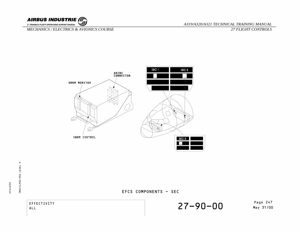
EFCS COMPONENTS - SECTMUFCLP02-P02 LEVEL 3
EFFECTIVITY 27-90-00 Page 5May 31/00
_A319/A320/A321 TECHNICAL TRAINING MANUAL27 FLIGHT CONTROLSMECHANICS / ELECTRICS & AVIONICS COURSE
UFD4200
Page 247EFFECTIVITYALL

EFCS COMPONENTS
Flight Control Data Concentrator (FCDC)
IDENTIFICATIONFIN: 3CE1, 3CE2
LOCATIONZONE: 83VU, 84VU
TMUFCLP02-T03 LEVEL 3
EFFECTIVITY 27-90-00 Page 6May 31/00
_A319/A320/A321 TECHNICAL TRAINING MANUAL27 FLIGHT CONTROLSMECHANICS / ELECTRICS & AVIONICS COURSE
UFD4200
Page 248EFFECTIVITYALL

EFCS COMPONENTS - FCDCTMUFCLP02-P03 LEVEL 3
EFFECTIVITY 27-90-00 Page 7May 31/00
_A319/A320/A321 TECHNICAL TRAINING MANUAL27 FLIGHT CONTROLSMECHANICS / ELECTRICS & AVIONICS COURSE
UFD4200
Page 249EFFECTIVITYALL

EFCS COMPONENTS
SIDE STICK
IDENTIFICATIONFIN: 4CE
LOCATIONZONE: 182VU, 193VU
SIDE STICK TRANSDUCER UNIT (SSTU)
IDENTIFICATIONFIN: 4CE1, 4CE4
LOCATIONZONE: 182VU, 193VU
COMPONENT DESCRIPTIONThe SSTU is a part of the sidestick assembly.
TMUFCLP02-T04 LEVEL 3
EFFECTIVITY 27-90-00 Page 8May 31/00
_A319/A320/A321 TECHNICAL TRAINING MANUAL27 FLIGHT CONTROLSMECHANICS / ELECTRICS & AVIONICS COURSE
UFD4200
Page 250EFFECTIVITYALL

EFCS COMPONENTS - SIDE STICK - SSTUTMUFCLP02-P04 LEVEL 3
EFFECTIVITY 27-90-00 Page 9May 31/00
_A319/A320/A321 TECHNICAL TRAINING MANUAL27 FLIGHT CONTROLSMECHANICS / ELECTRICS & AVIONICS COURSE
UFD4200
Page 251EFFECTIVITYALL

EFCS COMPONENTS
SPEED BRAKE CONTROL TRANSDUCER UNIT
IDENTIFICATIONFIN: 7CE
LOCATIONZONE: 11VU
COMPONENT DESCRIPTIONThere are two potentiometers per SEC in the speed brakecontrol transducer unit.
ACCELEROMETER
IDENTIFICATIONFIN: 12CE1, 12CE2, 12CE3, 12CE4.
LOCATIONZONE: 131VU, 132VU
TMUFCLP02-T05 LEVEL 3
EFFECTIVITY 27-90-00 Page 10May 31/00
_A319/A320/A321 TECHNICAL TRAINING MANUAL27 FLIGHT CONTROLSMECHANICS / ELECTRICS & AVIONICS COURSE
UFD4200
Page 252EFFECTIVITYALL

EFCS COMPONENTS - SPEED BRAKE CONTROL TRANSDUCER UNIT - ACCELEROMETERTMUFCLP02-P05 LEVEL 3
EFFECTIVITY 27-90-00 Page 11May 31/00
_A319/A320/A321 TECHNICAL TRAINING MANUAL27 FLIGHT CONTROLSMECHANICS / ELECTRICS & AVIONICS COURSE
UFD4200
Page 253EFFECTIVITYALL

THIS PAGE INTENTIONALLY LEFT BLANK
TMUFCLP02 LEVEL 3
EFFECTIVITY 27-90-00 Page 12May 31/00
_A319/A320/A321 TECHNICAL TRAINING MANUAL27 FLIGHT CONTROLSMECHANICS / ELECTRICS & AVIONICS COURSE
UFD4200
Page 254EFFECTIVITYALL

27 - FLIGHT CONTROLS
27-00-00 SLATS/FLAPS SYSTEM PRESENTATION
CONTENTS:GeneralSlat / Flap LeverSlat / Flap Control Computers (SFCCs)Power Control Units (PCUs)Position Pick-Off Units (PPUs)Wing Tip Brakes (WTBs)Flap SensorsSelf Examination
TMUFCTA02 LEVEL 1
EFFECTIVITY 27-00-00 Page 1May 31/00
_A319/A320/A321 TECHNICAL TRAINING MANUAL27 FLIGHT CONTROLSMECHANICS / ELECTRICS & AVIONICS COURSE
UFD4200
Page 255EFFECTIVITYALL

SLATS/FLAPS SYSTEM PRESENTATION
GENERAL
The high lift system includes two trailing edge flaps(double slotted for the A321) and five leading edgeslats on each wing. The surfaces are numbered from thewing root to the wing tip.The position of the surfaces is selected from a controllever which transmits the demand to the Slat FlapControl Computers (SFCCs) through a Command SensorUnit.The SFCCs, which are identical, ensure the control andmonitoring of the slat and flap system. On leverdemand, the SFCCs send signals to the Power ControlUnits (PCUs) to energize the valve blocks. Twohydraulic motors in each Power Control Unit providehydraulic actuation. Each of them is powered by adifferent hydraulic system and has its own valve blockand pressure off brake.The valve blocks control the direction of rotation andthe speed of their related PCU output shaft.The hydraulic motors move the transmission through adifferential gearbox. Then torque shafts and gearboxestransmit the mechanical power to the actuators whichdrive the surfaces. Wing tip brakes are provided inorder to stop and lock the system when certain typesof failures are detected. Feedback signals, sent bydedicated Position Pick Off Units, are used by thecomputers to control and monitor the system.A Feedback PPU provides signals concerning the PCUoutput position, while two Asymmetry PPUs sendinformation about surfaces actual position. Inaddition, signals from an Instrumentation PPU are usedfor position indicating on the ECAM.
SLAT / FLAP LEVER
Slat and flap positions are simultaneously selectedusing a single control lever located on the centerpedestal.Moving the lever rotates the input shaft of the CommandSensor Unit which translates the mechanical demandinto electrical signals for the SFCCs.
SLAT / FLAP CONTROL COMPUTERS
Two Slat Flap Control Computers (SFCCs) control andmonitor the system. Each computer includes one slatand one flap channel. A cross talk allows transfer ofdata between the SFCCs. On lever demand, each channelgenerates commands to energize its associated PCU valveblock and control its related motors.The computers monitor the slat and flap drives andlock the appropriate channel, should a critical failureoccur.They also inhibit slat retraction from position 1 to0 at high angle of attack or low speed (alpha-lockfunction ).With one SFCC inoperative, both slat and flap systemsoperate at half speed.
TMUFCTA02-T01 LEVEL 1
EFFECTIVITY 27-00-00 Page 2May 31/00
_A319/A320/A321 TECHNICAL TRAINING MANUAL27 FLIGHT CONTROLSMECHANICS / ELECTRICS & AVIONICS COURSE
UFD4200
Page 256EFFECTIVITYALL

SLATS/FLAPS SYSTEM PRESENTATIONTMUFCTA02-P01 LEVEL 1
EFFECTIVITY 27-00-00 Page 3May 31/00
_A319/A320/A321 TECHNICAL TRAINING MANUAL27 FLIGHT CONTROLSMECHANICS / ELECTRICS & AVIONICS COURSE
UFD4200
Page 257EFFECTIVITYALL

SLATS/FLAPS SYSTEM PRESENTATION
POWER CONTROL UNITS
Each PCU incorporates two separate hydraulic motorspowered through an electrically signalled valve blockwhich receives drive commands from the SFCCs.The motor output shafts on each PCU are coupled througha differential gearbox to drive the slat and flapmechanical channels.A Pressure Off Brake on each motor locks thetransmission:
- when the selected position is reached.- when there are no drive commands.- or in case of hydraulic power failure.
If one motor is inoperative, ( i.e. hydraulic failureor SFCC failure ), the remaining motor provides fulloutput torque at half speed.
POSITION PICK-OFF UNITS
The SFCCs monitor surface operation through dedicatedPosition Pick-Off Units.A Feedback unit and an Instrumentation PPU are mountedon each PCU. An Asymmetry PPU is installed at the endof the transmission system on each wing.The Intrumentation PPUs provide slat/flap actualposition data for indication on the ECAM through theFlight Warning Computer. The Asymmetry and FeedbackPPUs are used by the computers to monitor asymmetry,runaway or overspeed conditions.Asymmetry is detected on disagreement between the twoAPPU signals.Runaway is detected by comparison of both APPU andFPPU signals.Overspeed is detected when overspeed of one or morePPUs occurs due to high aerodynamic loads acting inthe same direction as the transmission.
TMUFCTA02-T01 LEVEL 1
EFFECTIVITY 27-00-00 Page 4May 31/00
_A319/A320/A321 TECHNICAL TRAINING MANUAL27 FLIGHT CONTROLSMECHANICS / ELECTRICS & AVIONICS COURSE
UFD4200
Page 258EFFECTIVITYALL

SLATS/FLAPS SYSTEM PRESENTATION
WING TIP BRAKES
The Wing Tip Brakes (WTBs) stop and hold thetransmission if the SFCCs detect certain types offailures such as asymmetry, runaway or overspeed.They are conceived as pressure on type brakes. Theyare released when solenoids are de-energized. EachWing Tip Brake is equipped with two solenoid valveseach controlled by a SFCC and supplied by an hydraulicsystem. In normal flight conditions , the solenoidsare de-energized.The segregation of the hydraulic circuits results ineither one being able to keep the brakes applied. Withone SFCC inoperative, the second one is still able toapply the Wing Tip Brake. Flap locking by the WTB doesnot prevent slat operation and vice versa. Once appliedthe WTB can be reset on ground only via the CentralizedFault Display System.
FLAP SENSORS
A flap disconnect detection system inhibits furtherflap operation when a flap attachment failure isdetected.It consists of two proximity sensors on eachinterconnecting strut (on each wing), which measuredifferential movement between inner and outer flaps.An electrically controlled, mechanically actuatedsensor unit including two sensors is installed onthe flap interconnecting strut.If a flap disconnect is detected, the flap PCU isde-energized and the Pressure Off Brakes areapplied in order to stop the transmission.Further flap operation is inhibited (WTBs are notapplied).
TMUFCTA02-T01 LEVEL 1
EFFECTIVITY 27-00-00 Page 5May 31/00
_A319/A320/A321 TECHNICAL TRAINING MANUAL27 FLIGHT CONTROLSMECHANICS / ELECTRICS & AVIONICS COURSE
UFD4200
Page 259EFFECTIVITYALL
SELF EXAMINATION
What are the conseqences of one flap PCU motorinoperative ?
A - No consequence. The movement of the flapsurfaces is not affected.
B - The system is locked and flap movementis no longer possible.
C - The flap surfaces extend (retract) athalf speed.
TMUFCTA02 LEVEL 1
EFFECTIVITY 27-00-00 Page 6May 31/00
_A319/A320/A321 TECHNICAL TRAINING MANUAL27 FLIGHT CONTROLSMECHANICS / ELECTRICS & AVIONICS COURSE
UFD4200
Page 260EFFECTIVITYALL

27 - FLIGHT CONTROLS
27-00-00 SLATS AND FLAPS CONTROL ANDPOSITION INDICATION
CONTENTS:Slats / Flaps Control LeverSlats / Flaps Extension On GroundSlats / Flaps Retraction On GroundSlats / Flaps Extension In FlightSlats / Flaps Retraction In FlightAutomatic Retraction In FlightSlats Alpha-Lock ProtectionSelf Examination
TMUFC1602 LEVEL 1
EFFECTIVITY 27-00-00 Page 1May 31/00
_A319/A320/A321 TECHNICAL TRAINING MANUAL27 FLIGHT CONTROLSMECHANICS / ELECTRICS & AVIONICS COURSE
UFD4200
Page 261EFFECTIVITYALL

SLATS AND FLAPS CONTROL AND POSITION INDICATION
SLATS / FLAPS CONTROL LEVER
The Slats / Flaps control lever is located in thecockpit on the center pedestal.It is connected to the Command Sensor Unit whichtransforms the mechanical demand into electricalsignals for the Slat / Flap Control Computers (SFCCs).The lever selects simultaneous operation of the slatsand flaps and the collar must be lifted beforeselection of any position.The relationship between the lever position, flightphase and slat flap angles is shown here.
TMUFC1602-T01 LEVEL 1
EFFECTIVITY 27-00-00 Page 2May 31/00
_A319/A320/A321 TECHNICAL TRAINING MANUAL27 FLIGHT CONTROLSMECHANICS / ELECTRICS & AVIONICS COURSE
UFD4200
Page 262EFFECTIVITYALL

SLATS AND FLAPS CONTROL AND POSITION INDICATION - CONTROL LEVER
TMUFC1602-P01 LEVEL 1
EFFECTIVITY 27-00-00 Page 3May 31/00
_A319/A320/A321 TECHNICAL TRAINING MANUAL27 FLIGHT CONTROLSMECHANICS / ELECTRICS & AVIONICS COURSE
UFD4200
Page 263EFFECTIVITYALL

SLATS AND FLAPS CONTROL AND POSITION INDICATION
SLATS / FLAPS EXTENSION ON GROUND
The white points on the ECAM display are the selectableSlat / Flap positions. These white points are notdisplayed in clean configuration.A word "FLAP" appears on the ECAM display when theslats and flaps are not fully retracted.When a new position is selected, the position number,the word "FLAP" and the selected position trianglesare displayed in cyan.When the selected position is reached, the positionnumber, and triangles become green. The word "FLAP"becomes white. A green line is added to the display.When the flaps are set to full, the word FULL replacesthe flap position number.
TMUFC1602-T02 LEVEL 1
EFFECTIVITY 27-00-00 Page 4May 31/00
_A319/A320/A321 TECHNICAL TRAINING MANUAL27 FLIGHT CONTROLSMECHANICS / ELECTRICS & AVIONICS COURSE
UFD4200
Page 264EFFECTIVITYALL

SLATS AND FLAPS CONTROL AND POSITION INDICATION - EXTENSION ON GROUND
TMUFC1602-P02 LEVEL 1
EFFECTIVITY 27-00-00 Page 5May 31/00
_A319/A320/A321 TECHNICAL TRAINING MANUAL27 FLIGHT CONTROLSMECHANICS / ELECTRICS & AVIONICS COURSE
UFD4200
Page 265EFFECTIVITYALL

SLATS AND FLAPS CONTROL AND POSITION INDICATION
SLATS / FLAPS RETRACTION ON GROUND
With the aircraft on ground, the configuration is 1+F.Once the surfaces have reached the fully retractedposition, the clean configuration is displayed on theECAM display.
TMUFC1602-T03 LEVEL 1
EFFECTIVITY 27-00-00 Page 6May 31/00
_A319/A320/A321 TECHNICAL TRAINING MANUAL27 FLIGHT CONTROLSMECHANICS / ELECTRICS & AVIONICS COURSE
UFD4200
Page 266EFFECTIVITYALL

SLATS AND FLAPS CONTROL AND POSITION INDICATION - RETRACTION ON GROUND
TMUFC1602-P03 LEVEL 1
EFFECTIVITY 27-00-00 Page 7May 31/00
_A319/A320/A321 TECHNICAL TRAINING MANUAL27 FLIGHT CONTROLSMECHANICS / ELECTRICS & AVIONICS COURSE
UFD4200
Page 267EFFECTIVITYALL

SLATS AND FLAPS CONTROL AND POSITION INDICATION
SLATS / FLAPS EXTENSION IN FLIGHT
In flight, there are two configurations, depending onspeed, for extension from 0 to position 1:
- Speed above 100kt.- Speed below 100kt.
For position 2 to Full, the deflection angles are thesame as those mentioned for extension on ground.NOTE : Extension to position 1 on ground both Slatsand Flaps extend.
TMUFC1602-T04 LEVEL 1
EFFECTIVITY 27-00-00 Page 8May 31/00
_A319/A320/A321 TECHNICAL TRAINING MANUAL27 FLIGHT CONTROLSMECHANICS / ELECTRICS & AVIONICS COURSE
UFD4200
Page 268EFFECTIVITYALL

SLATS AND FLAPS CONTROL AND POSITION INDICATION - EXTENSION IN FLIGHTTMUFC1602-P04 LEVEL 1
EFFECTIVITY 27-00-00 Page 9May 31/00
_A319/A320/A321 TECHNICAL TRAINING MANUAL27 FLIGHT CONTROLSMECHANICS / ELECTRICS & AVIONICS COURSE
UFD4200
Page 269EFFECTIVITYALL

SLATS AND FLAPS CONTROL AND POSITION INDICATION
SLATS / FLAPS RETRACTION IN FLIGHT
Retraction from fully extended, to position 3 and fromposition 3 to position 2 is identical to surfaceretraction on ground.There are two configurations, depending on speed, forretraction to position 1 in flight:
- Speed above 210kt.- Speed below 210kt.
TMUFC1602-T05 LEVEL 1
EFFECTIVITY 27-00-00 Page 10May 31/00
_A319/A320/A321 TECHNICAL TRAINING MANUAL27 FLIGHT CONTROLSMECHANICS / ELECTRICS & AVIONICS COURSE
UFD4200
Page 270EFFECTIVITYALL

SLATS AND FLAPS CONTROL AND POSITION INDICATION - RETRACTION IN FLIGHT
TMUFC1602-P05 LEVEL 1
EFFECTIVITY 27-00-00 Page 11May 31/00
_A319/A320/A321 TECHNICAL TRAINING MANUAL27 FLIGHT CONTROLSMECHANICS / ELECTRICS & AVIONICS COURSE
UFD4200
Page 271EFFECTIVITYALL

SLATS AND FLAPS CONTROL AND POSITION INDICATION
AUTOMATIC RETRACTION IN FLIGHT
The present speed is lower than 210 knots and theconfiguration is 1+F.The flap auto function is engaged. When the computedairspeed reaches 210 knots, the flaps retractautomatically to 0 and the new slat flap configurationis 1.Note that, when take off is performed in config 1+F,flaps fully retract automatically at 210 knots ifconfig 0 is not selected after take off.
- Speed below 210kt - Slats 18° / Flaps 10°- Speed above 210kt - Slats 18° / Flaps 0°
After an automatic flap retraction, there is noautomatic re-extension if the speed drops below 210knots.
TMUFC1602-T06 LEVEL 1
EFFECTIVITY 27-00-00 Page 12May 31/00
_A319/A320/A321 TECHNICAL TRAINING MANUAL27 FLIGHT CONTROLSMECHANICS / ELECTRICS & AVIONICS COURSE
UFD4200
Page 272EFFECTIVITYALL

SLATS AND FLAPS CONTROL AND POSITION INDICATION - AUTOMATIC RETRACTION IN FLIGHT
TMUFC1602-P06 LEVEL 1
EFFECTIVITY 27-00-00 Page 13May 31/00
_A319/A320/A321 TECHNICAL TRAINING MANUAL27 FLIGHT CONTROLSMECHANICS / ELECTRICS & AVIONICS COURSE
UFD4200
Page 273EFFECTIVITYALL

SLATS AND FLAPS CONTROL AND POSITION INDICATION
SLATS ALPHA-LOCK PROTECTION
Slat retraction from position 1 to 0 is inhibited toprevent the aircraft from stalling when the Angle OfAttack (AOA) is high (alpha-lock) or the speed is toolow.The slat channels of the SFCCs receive corrected AngleOf Attack (AOA) and computed airspeed (CAS) providedby the ADIRUs for use in alpha lock computation. Acyan pulsing "A-LOCK" message is displayed to indicatethe retraction inhibition. Slat retraction from 18° to 0° is prevented if:
- AOA greater than 8.5° or CAS lower than 148kt.The alpha-lock function is reset if:
- AOA lower than 7.6° and CAS greater than 154kt.The function is not active if:
- The aircraft is on ground with CAS lower than60kt.
- AOA exceeds 8°5 or CAS drops below 148ktwhile retraction from 18° to 0° has alreadystarted.
TMUFC1602-T07 LEVEL 1
EFFECTIVITY 27-00-00 Page 14May 31/00
_A319/A320/A321 TECHNICAL TRAINING MANUAL27 FLIGHT CONTROLSMECHANICS / ELECTRICS & AVIONICS COURSE
UFD4200
Page 274EFFECTIVITYALL

SLATS AND FLAPS CONTROL AND POSITION INDICATION - SLATS ALPHA-LOCK PROTECTION
TMUFC1602-P07 LEVEL 1
EFFECTIVITY 27-00-00 Page 15May 31/00
_A319/A320/A321 TECHNICAL TRAINING MANUAL27 FLIGHT CONTROLSMECHANICS / ELECTRICS & AVIONICS COURSE
UFD4200
Page 275EFFECTIVITYALL
SELF EXAMINATION
What happens when Slats/Flaps configuration is 1+Fand the CAS reaches 210 knots?
A - Flaps retract automatically to 0 and thenew Slats/Flaps configuration is 1.
B - Flaps extend automatically because thespeed is too high.
C - The alpha lock function is engagedbecause the CAS is too high.
TMUFC1602 LEVEL 1
EFFECTIVITY 27-00-00 Page 16May 31/00
_A319/A320/A321 TECHNICAL TRAINING MANUAL27 FLIGHT CONTROLSMECHANICS / ELECTRICS & AVIONICS COURSE
UFD4200
Page 276EFFECTIVITYALL

27 - FLIGHT CONTROLS
27-00-00 SLATS AND FLAPS CONTROL ANDPOSITION INDICATION
CONTENTS:Slats / Flaps Control LeverSlats / Flaps Extension On GroundSlats / Flaps Retraction On GroundSlats / Flaps Extension In FlightSlats / Flaps Retraction In FlightAutomatic Retraction In FlightSlats Alpha-Lock ProtectionSelf Examination
TMUFC1603 LEVEL 1
EFFECTIVITY 27-00-00 Page 1May 31/00
_A319/A320/A321 TECHNICAL TRAINING MANUAL27 FLIGHT CONTROLSMECHANICS / ELECTRICS & AVIONICS COURSE
UFD4200
Page 277EFFECTIVITYALL

SLATS AND FLAPS CONTROL AND POSITION INDICATION
SLATS / FLAPS CONTROL LEVER
The Slats / Flaps control lever is located in thecockpit on the center pedestal.It is connected to the Command Sensor Unit whichtransforms the mechanical demand into electricalsignals for the Slat / Flap Control Computers (SFCCs).The lever selects simultaneous operation of the slatsand flaps and the collar must be lifted beforeselection of any position.The relationship between the lever position, flightphase and slat flap angles is shown here.
TMUFC1603-T01 LEVEL 1
EFFECTIVITY 27-00-00 Page 2May 31/00
_A319/A320/A321 TECHNICAL TRAINING MANUAL27 FLIGHT CONTROLSMECHANICS / ELECTRICS & AVIONICS COURSE
UFD4200
Page 278EFFECTIVITYALL
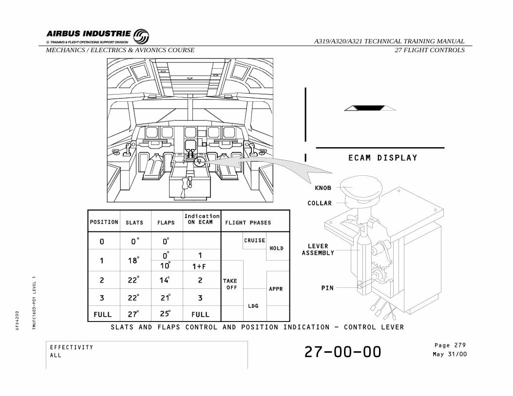
SLATS AND FLAPS CONTROL AND POSITION INDICATION - CONTROL LEVERTMUFC1603-P01 LEVEL 1
EFFECTIVITY 27-00-00 Page 3May 31/00
_A319/A320/A321 TECHNICAL TRAINING MANUAL27 FLIGHT CONTROLSMECHANICS / ELECTRICS & AVIONICS COURSE
UFD4200
Page 279EFFECTIVITYALL

SLATS AND FLAPS CONTROL AND POSITION INDICATION
SLATS / FLAPS EXTENSION ON GROUND
The white points on the ECAM display are the selectableSlat / Flap positions. These white points are notdisplayed in clean configuration.A word "FLAP" appears on the ECAM display when theslats and flaps are not fully retracted.When a new position is selected, the position number,the word "FLAP" and the selected position trianglesare displayed in cyan.When the selected position is reached, the positionnumber, and triangles become green. The word "FLAP"becomes white. A green line is added to the display.When the flaps are set to full, the word FULL replacesthe flap position number.
TMUFC1603-T02 LEVEL 1
EFFECTIVITY 27-00-00 Page 4May 31/00
_A319/A320/A321 TECHNICAL TRAINING MANUAL27 FLIGHT CONTROLSMECHANICS / ELECTRICS & AVIONICS COURSE
UFD4200
Page 280EFFECTIVITYALL

SLATS AND FLAPS CONTROL AND POSITION INDICATION - EXTENSION ON GROUNDTMUFC1603-P02 LEVEL 1
EFFECTIVITY 27-00-00 Page 5May 31/00
_A319/A320/A321 TECHNICAL TRAINING MANUAL27 FLIGHT CONTROLSMECHANICS / ELECTRICS & AVIONICS COURSE
UFD4200
Page 281EFFECTIVITYALL

SLATS AND FLAPS CONTROL AND POSITION INDICATION
SLATS / FLAPS RETRACTION ON GROUND
With the aircraft on ground, the configuration is 1+F.Once the surfaces have reached the fully retractedposition, the clean configuration is displayed on theECAM display.
TMUFC1603-T03 LEVEL 1
EFFECTIVITY 27-00-00 Page 6May 31/00
_A319/A320/A321 TECHNICAL TRAINING MANUAL27 FLIGHT CONTROLSMECHANICS / ELECTRICS & AVIONICS COURSE
UFD4200
Page 282EFFECTIVITYALL

SLATS AND FLAPS CONTROL AND POSITION INDICATION - RETRACTION ON GROUNDTMUFC1603-P03 LEVEL 1
EFFECTIVITY 27-00-00 Page 7May 31/00
_A319/A320/A321 TECHNICAL TRAINING MANUAL27 FLIGHT CONTROLSMECHANICS / ELECTRICS & AVIONICS COURSE
UFD4200
Page 283EFFECTIVITYALL
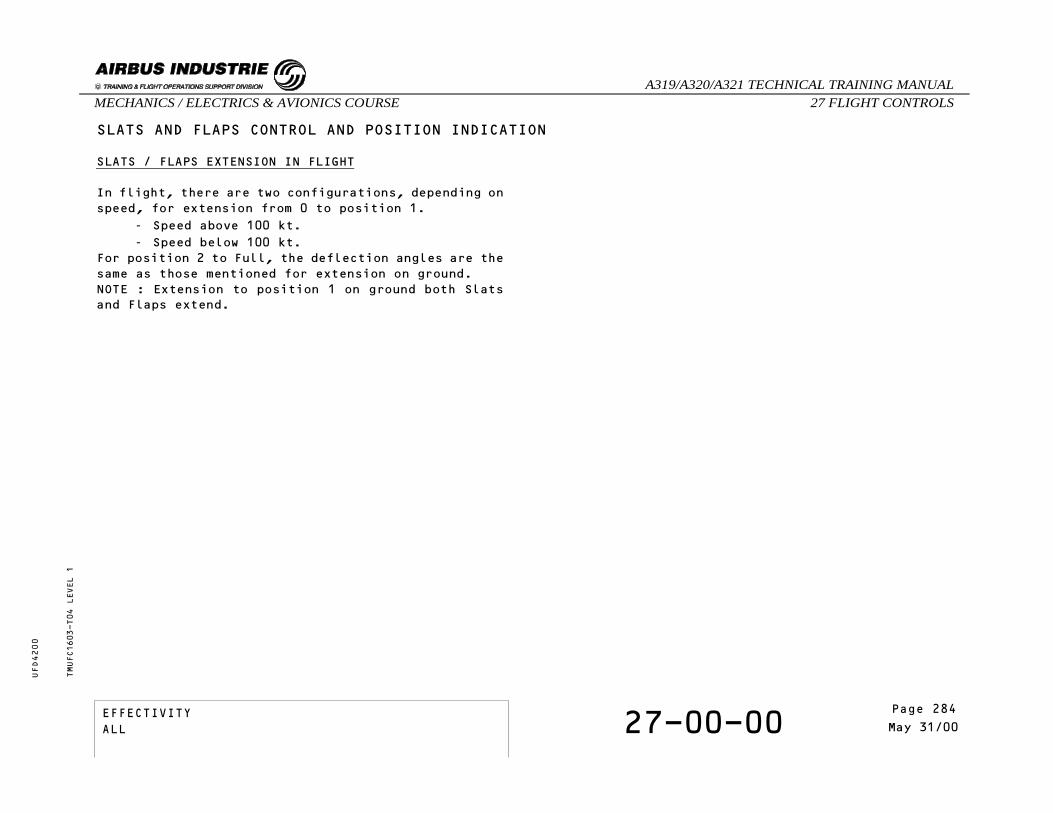
SLATS AND FLAPS CONTROL AND POSITION INDICATION
SLATS / FLAPS EXTENSION IN FLIGHT
In flight, there are two configurations, depending onspeed, for extension from 0 to position 1.
- Speed above 100 kt.- Speed below 100 kt.
For position 2 to Full, the deflection angles are thesame as those mentioned for extension on ground.NOTE : Extension to position 1 on ground both Slatsand Flaps extend.
TMUFC1603-T04 LEVEL 1
EFFECTIVITY 27-00-00 Page 8May 31/00
_A319/A320/A321 TECHNICAL TRAINING MANUAL27 FLIGHT CONTROLSMECHANICS / ELECTRICS & AVIONICS COURSE
UFD4200
Page 284EFFECTIVITYALL

SLATS AND FLAPS CONTROL AND POSITION INDICATION - EXTENSION IN FLIGHTTMUFC1603-P04 LEVEL 1
EFFECTIVITY 27-00-00 Page 9May 31/00
_A319/A320/A321 TECHNICAL TRAINING MANUAL27 FLIGHT CONTROLSMECHANICS / ELECTRICS & AVIONICS COURSE
UFD4200
Page 285EFFECTIVITYALL
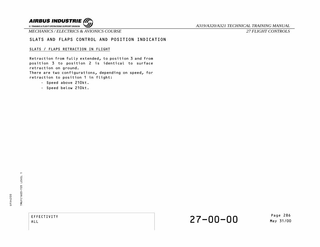
SLATS AND FLAPS CONTROL AND POSITION INDICATION
SLATS / FLAPS RETRACTION IN FLIGHT
Retraction from fully extended, to position 3 and fromposition 3 to position 2 is identical to surfaceretraction on ground.There are two configurations, depending on speed, forretraction to position 1 in flight:
- Speed above 210kt.- Speed below 210kt.
TMUFC1603-T05 LEVEL 1
EFFECTIVITY 27-00-00 Page 10May 31/00
_A319/A320/A321 TECHNICAL TRAINING MANUAL27 FLIGHT CONTROLSMECHANICS / ELECTRICS & AVIONICS COURSE
UFD4200
Page 286EFFECTIVITYALL

SLATS AND FLAPS CONTROL AND POSITION INDICATION - RETRACTION IN FLIGHTTMUFC1603-P05 LEVEL 1
EFFECTIVITY 27-00-00 Page 11May 31/00
_A319/A320/A321 TECHNICAL TRAINING MANUAL27 FLIGHT CONTROLSMECHANICS / ELECTRICS & AVIONICS COURSE
UFD4200
Page 287EFFECTIVITYALL
SLATS AND FLAPS CONTROL AND POSITION INDICATION
AUTOMATIC RETRACTION IN FLIGHT
The present speed is lower than 210 knots and theconfiguration is 1+F.The flap auto function is engaged. When the computedairspeed reaches 210 knots, the flaps retractautomatically to 0 and the new slat flap configurationis 1.Note that, when take off is performed in config 1+F,flaps fully retract automatically at 210 knots ifconfig 0 is not selected after take off.
- Speed below 210kt - Slats 18° / Flaps 10°,- Speed above 210kt - Slats 18° / Flaps 0°.
After an automatic flap retraction, there is noautomatic re-extension if the speed drops below 210knots.
TMUFC1603-T06 LEVEL 1
EFFECTIVITY 27-00-00 Page 12May 31/00
_A319/A320/A321 TECHNICAL TRAINING MANUAL27 FLIGHT CONTROLSMECHANICS / ELECTRICS & AVIONICS COURSE
UFD4200
Page 288EFFECTIVITYALL

SLATS AND FLAPS CONTROL AND POSITION INDICATION - AUTOMATIC RETRACTION IN FLIGHTTMUFC1603-P06 LEVEL 1
EFFECTIVITY 27-00-00 Page 13May 31/00
_A319/A320/A321 TECHNICAL TRAINING MANUAL27 FLIGHT CONTROLSMECHANICS / ELECTRICS & AVIONICS COURSE
UFD4200
Page 289EFFECTIVITYALL
SLATS AND FLAPS CONTROL AND POSITION INDICATION
SLATS ALPHA-LOCK PROTECTION
Slat retraction from position 1 to 0 is inhibited toprevent the aircraft from stalling when the Angle OfAttack is high (alpha-lock) or the speed is too low.The slat channels of the SFCCs receive corrected AngleOf Attack (AOA) and computed airspeed (CAS) providedby the ADIRUs for use in alpha lock computation. Acyan pulsing "A-LOCK" message is displayed to indicatethe retraction inhibition. Slat retraction from 18° to 0° is prevented if:
- AOA greater than 8° or CAS lower than 165kt.The alpha-lock function is reset if:
- AOA lower than 7.1° and CAS greater than 171kt.The function is not active if:
- The aircraft is on ground with CAS lower than60kt.
- AOA exceeds 8° or CAS drops below 165ktwhile retraction from 18° to 0° has alreadystarted.
TMUFC1603-T07 LEVEL 1
EFFECTIVITY 27-00-00 Page 14May 31/00
_A319/A320/A321 TECHNICAL TRAINING MANUAL27 FLIGHT CONTROLSMECHANICS / ELECTRICS & AVIONICS COURSE
UFD4200
Page 290EFFECTIVITYALL

SLATS AND FLAPS CONTROL AND POSITION INDICATION - SLATS ALPHA-LOCK PROTECTIONTMUFC1603-P07 LEVEL 1
EFFECTIVITY 27-00-00 Page 15May 31/00
_A319/A320/A321 TECHNICAL TRAINING MANUAL27 FLIGHT CONTROLSMECHANICS / ELECTRICS & AVIONICS COURSE
UFD4200
Page 291EFFECTIVITYALL

SELF EXAMINATION
What happens when Slat/Flap configuration is 1+Fand the CAS reaches 210 knots?
A - Flaps retract automatically to 0 and thenew Slat/Flap configuration is 1.
B - Flaps extend automatically because thespeed is too high.
C - The alpha lock function is engagedbecause the CAS is too high.
TMUFC1603 LEVEL 1
EFFECTIVITY 27-00-00 Page 16May 31/00
_A319/A320/A321 TECHNICAL TRAINING MANUAL27 FLIGHT CONTROLSMECHANICS / ELECTRICS & AVIONICS COURSE
UFD4200
Page 292EFFECTIVITYALL

27 - FLIGHT CONTROLS
27-00-00 SLATS/FLAPS CONTROL
CONTENTS:Extension SequenceSelf Examination
TMUFCTG01 LEVEL 3
EFFECTIVITY 27-00-00 Page 1Mar 31/00
_A319/A320/A321 TECHNICAL TRAINING MANUAL27 FLIGHT CONTROLSMECHANICS / ELECTRICS & AVIONICS COURSE
UFD4200
Page 293EFFECTIVITYALL
SLATS/FLAPS CONTROL
EXTENSION SEQUENCE
This presentation shows detailed operation of the PowerControl Unit (PCU) and the Slat Flap Control Computer(SFCC), through a normal extension sequence.As slat and flap control is identical, only the flapsystem is shown.Each valve block includes three solenoid valves. Twoof them, called directional valves, command the controlvalve spool for retraction (RET) or extension (EXT),while the enable solenoid valve (ENB) controls thePressure Off Brake (POB).Moving the slat flap lever rotates the Command SensorUnit (CSU) which issues a new position demand signalto each Slat Flap Control Computer (SFCC).This signal is processed in flap lanes 1 and 2.The position demand and the actual position from theFeedback Position Pick off Unit (FPPU) are comparedin the SFCC flap lanes.If the demanded and actual positions are different,each lane generates command signals.The command signals generated by each lane arecompared.If the command signals are in agreement, drive commandsare generated for PCU valve block activation.Each SFCC controls its related solenoid valve.
TMUFCTG01-T01 LEVEL 3
EFFECTIVITY 27-00-00 Page 2Mar 31/00
_A319/A320/A321 TECHNICAL TRAINING MANUAL27 FLIGHT CONTROLSMECHANICS / ELECTRICS & AVIONICS COURSE
UFD4200
Page 294EFFECTIVITYALL

TMUFCTG01-P01 LEVEL 3
SLATS/FLAPS CONTROL - EXTENSION SEQUENCE
EFFECTIVITY 27-00-00 Page 3Mar 31/00
_A319/A320/A321 TECHNICAL TRAINING MANUAL27 FLIGHT CONTROLSMECHANICS / ELECTRICS & AVIONICS COURSE
UFD4200
Page 295EFFECTIVITYALL

SLATS/FLAPS CONTROL
EXTENSION SEQUENCE
As the extend solenoid is energized, the control valvespool moves from neutral towards the fully deflectedposition.The direction of valve spool movements controls thedirection of rotation of the motor.The degree of valve spool movement controls therotation speed of the motor.The position of the control valve spool is monitoredby a Linear Variable Differential Transducer (LVDT)mounted on one end of the valve block.The enable solenoid valve is energized to release thePressure Off Brake (POB), and the flaps begin toextend.With the control valve spool fully deflected, themaximum available fluid flow is directed to the motorswhich run at full speed for flap extension.As the flaps approach the demanded position, theretract solenoid is energized permitting the controlvalve spool to move back to neutral position.The control valve spool movement reduces the fluidflow which in turn reduces the motor speed.
TMUFCTG01-T02 LEVEL 3
EFFECTIVITY 27-00-00 Page 4Mar 31/00
_A319/A320/A321 TECHNICAL TRAINING MANUAL27 FLIGHT CONTROLSMECHANICS / ELECTRICS & AVIONICS COURSE
UFD4200
Page 296EFFECTIVITYALL

TMUFCTG01-P02 LEVEL 3
SLATS/FLAPS CONTROL - EXTENSION SEQUENCE
EFFECTIVITY 27-00-00 Page 5Mar 31/00
_A319/A320/A321 TECHNICAL TRAINING MANUAL27 FLIGHT CONTROLSMECHANICS / ELECTRICS & AVIONICS COURSE
UFD4200
Page 297EFFECTIVITYALL

SLATS/FLAPS CONTROL
EXTENSION SEQUENCE
When the flaps reach the demanded position, allsolenoid valves are de-energized and the Pressure OffBrake is applied.The motor stops and the Pressure Off Brake (POB) isapplied to lock the flaps until a new position isdemanded.
TMUFCTG01-T03 LEVEL 3
EFFECTIVITY 27-00-00 Page 6Mar 31/00
_A319/A320/A321 TECHNICAL TRAINING MANUAL27 FLIGHT CONTROLSMECHANICS / ELECTRICS & AVIONICS COURSE
UFD4200
Page 298EFFECTIVITYALL

SLATS/FLAPS CONTROL - EXTENSION SEQUENCETMUFCTG01-P03 LEVEL 3
EFFECTIVITY 27-00-00 Page 7Mar 31/00
_A319/A320/A321 TECHNICAL TRAINING MANUAL27 FLIGHT CONTROLSMECHANICS / ELECTRICS & AVIONICS COURSE
UFD4200
Page 299EFFECTIVITYALL

SELF EXAMINATION
What is the Pressure Off Brake controlled by ?A - One of the two directional valves.B - The enable solenoid valve.C - The Linear Variable Differential
Transducer.
Why is the retract solenoid energized duringextension ?
A - To reduce the rate of flap travel.B - To increase fluid flow to the motor.C - To lock flaps until next position demand.
TMUFCTG01 LEVEL 3
EFFECTIVITY 27-00-00 Page 8Mar 31/00
_A319/A320/A321 TECHNICAL TRAINING MANUAL27 FLIGHT CONTROLSMECHANICS / ELECTRICS & AVIONICS COURSE
UFD4200
Page 300EFFECTIVITYALL

27 - FLIGHT CONTROLS
27-00-00 SLATS/FLAPS ABNORMAL OPERATION(LOCKING)
CONTENTS:GeneralAsymmetryRunawayOverspeedUncommanded MovementFailure MonitoringSelf Examination
TMUFCTC02 LEVEL 3
EFFECTIVITYALL 27-00-00 Page 1
May 31/00
_A319/A320/A321 TECHNICAL TRAINING MANUAL27 FLIGHT CONTROLSMECHANICS / ELECTRICS & AVIONICS COURSE
UFD4200
Page 301EFFECTIVITYALL

SLATS/FLAPS ABNORMAL OPERATION (LOCKING)
GENERAL
Here is a brief reminder of the wing tip brakeapplication logic. Asymmetry, Runaway, Overspeed andUncommanded Movement are detected by cross comparisonof Asymmetry Position Pick-off Unit (APPU) and FeedbackPosition Pick-off Unit (FPPU) signals.
If any of these failures are detected by a Slat FlapControl Computer (SFCC) and confirmed by the secondone, the wing tip brakes are applied.
Note that if an SFCC does not operate, the other SFCCreceives a WTB-arm signal automatically.Thus, if the second SFCC subsequently detects afailure, a solenoid valve on each WTB is energized.
TMUFCTC02-T01 LEVEL 3
EFFECTIVITYALL 27-00-00 Page 2
May 31/00
_A319/A320/A321 TECHNICAL TRAINING MANUAL27 FLIGHT CONTROLSMECHANICS / ELECTRICS & AVIONICS COURSE
UFD4200
Page 302EFFECTIVITYALL

TMUFCTC02-P01 LEVEL 3
SLATS/FLAPS ABNORMAL OPERATION (LOCKING) - GENERAL
EFFECTIVITYALL 27-00-00 Page 3
May 31/00
_A319/A320/A321 TECHNICAL TRAINING MANUAL27 FLIGHT CONTROLSMECHANICS / ELECTRICS & AVIONICS COURSE
UFD4200
Page 303EFFECTIVITYALL

SLATS/FLAPS ABNORMAL OPERATION (LOCKING)
ASYMMETRY
Asymmetry is defined as a positional differencebetween the left hand and right hand Asymmetry PPUs.
Asymmetry is usually due to a broken shaft betweenboth APPUs.The Asymmetry threshold is above 5° synchropositional difference between both APPUs.
RUNAWAY
A Runaway is given as a positional difference betweenboth Asymmetry PPUs and the Feedback PPU.
Runaway on slats can occur when a component of thetorque shaft drive, common to the LH and RH wingsbreaks, leaving the slat system free from the PCU POB.This results in airloads tending to retract thesurfaces.Runaway on flaps can only be possible if the powercontrol unit gear box is broken. Depending on thebroken position, the airload tends to retract or extendthe flaps.
OVERSPEED
An Overspeed is detected when the rotation speed ofthe torque shafts measured at the PPUs is too high.
TMUFCTC02-T02 LEVEL 3
EFFECTIVITYALL 27-00-00 Page 4
May 31/00
_A319/A320/A321 TECHNICAL TRAINING MANUAL27 FLIGHT CONTROLSMECHANICS / ELECTRICS & AVIONICS COURSE
UFD4200
Page 304EFFECTIVITYALL

TMUFCTC02-P02 LEVEL 3
SLATS/FLAPS ABNORMAL OPERATION (LOCKING)- ASYMMETRY - RUNAWAY - OVERSPEED
EFFECTIVITYALL 27-00-00 Page 5
May 31/00
_A319/A320/A321 TECHNICAL TRAINING MANUAL27 FLIGHT CONTROLSMECHANICS / ELECTRICS & AVIONICS COURSE
UFD4200
Page 305EFFECTIVITYALL

SLATS/FLAPS ABNORMAL OPERATION (LOCKING)
UNCOMMANDED MOVEMENT
Uncommanded Movement is defined as a movement awayfrom the selected position by a value which exceedsthe threshold.
TMUFCTC02-T03 LEVEL 3
EFFECTIVITYALL 27-00-00 Page 6
May 31/00
_A319/A320/A321 TECHNICAL TRAINING MANUAL27 FLIGHT CONTROLSMECHANICS / ELECTRICS & AVIONICS COURSE
UFD4200
Page 306EFFECTIVITYALL

TMUFCTC02-P03 LEVEL 3
SLATS/FLAPS ABNORMAL OPERATION (LOCKING) - UNCOMMANDED MOVEMENT
EFFECTIVITYALL 27-00-00 Page 7
May 31/00
_A319/A320/A321 TECHNICAL TRAINING MANUAL27 FLIGHT CONTROLSMECHANICS / ELECTRICS & AVIONICS COURSE
UFD4200
Page 307EFFECTIVITYALL

SLATS/FLAPS ABNORMAL OPERATION (LOCKING)
FAILURE MONITORING
The Power Control Unit (PCU) is in operation.The extend solenoid valve and the pressure off brakesolenoid valve are energized and the flaps extend.
Position Pick-off Unit information is used for systemmonitoring.
Asymmetry is detected by SFCC1.Once asymmetry has been detected by an SFCC, itsassociated valve block is de-energized.
A "WTB arm" signal is sent to the SFCC2 flap channelto check whether asymmetry is confirmed or not.
If the asymmetry is confirmed by SFCC2, a "WTB arm"signal is sent to the WTB solenoids, PCUs arede-energized and the software latched (reset on groundonly via the CFDS).
If asymmetry is not confirmed by the second computer,the first system is considered faulty.
TMUFCTC02-T04 LEVEL 3
EFFECTIVITYALL 27-00-00 Page 8
May 31/00
_A319/A320/A321 TECHNICAL TRAINING MANUAL27 FLIGHT CONTROLSMECHANICS / ELECTRICS & AVIONICS COURSE
UFD4200
Page 308EFFECTIVITYALL

TMUFCTC02-P04 LEVEL 3
SLATS/FLAPS ABNORMAL OPERATION (LOCKING) - FAILURE MONITORING
EFFECTIVITYALL 27-00-00 Page 9
May 31/00
_A319/A320/A321 TECHNICAL TRAINING MANUAL27 FLIGHT CONTROLSMECHANICS / ELECTRICS & AVIONICS COURSE
UFD4200
Page 309EFFECTIVITYALL
SELF EXAMINATION
Which type of failure is detected with a positiondifference between both APPUs ?
A - An asymmetry.B - An overspeed.C - A runaway.
Once the WTBs have been applied, is it possible toreset them in flight ?
A - Yes, by making any new selection withthe control lever.
B - Yes, by making a reverse selection withthe control lever.
C - No, reset is possible on ground only.
How can a flap runaway be detected ? A - By comparison between the SFCC commands
and the Asymmetry PPU signals.B - By comparison between the SFCC commands
and the Feedback PPU signals.C - By comparison between Asymmetry PPU and
Feedback PPU signals.
TMUFCTC02 LEVEL 3
EFFECTIVITYALL 27-00-00 Page 10
May 31/00
_A319/A320/A321 TECHNICAL TRAINING MANUAL27 FLIGHT CONTROLSMECHANICS / ELECTRICS & AVIONICS COURSE
UFD4200
Page 310EFFECTIVITYALL

27 - FLIGHT CONTROLS
27-00-00 SLATS/FLAPS ABNORMAL OPERATION(HALF SPEED)
CONTENTS:PresentationSlat Flap Control Computer (SFCC) FailureHydraulic FailureSpool Valve JamSelf Examination
TMUFCTD02 LEVEL 3
EFFECTIVITYALL 27-00-00 Page 1
May 31/00
_A319/A320/A321 TECHNICAL TRAINING MANUAL27 FLIGHT CONTROLSMECHANICS / ELECTRICS & AVIONICS COURSE
UFD4200
Page 311EFFECTIVITYALL

SLATS/FLAPS ABNORMAL OPERATION (HALF SPEED)
PRESENTATION
We will study examples of abnormal operations whichcause the system to operate at half speed. As Slat andFlap operation is identical, only flaps will be shown.When half speed is detected, a level 1 caution isgenerated and a fault message is displayed on the ECAM.
SLAT AND FLAP CONTROL COMPUTER (SFCC) FAILURE
In this example Slat Flap Control Computer 2 flapchannel is inoperative and Slat Flap Control Computer1 operates normally.Each flap channel lane of the SFCC 1, generates commandsignals.The drive commands, generated in the POWER CONTROLUNIT control input stage, control the related solenoidvalve in the flap Power Control Unit.Only the related green hydraulic motor is operative.As valve block 24CV is not energized, the Pressure OffBrake holds the output shaft of the yellow hydraulicmotor. Due to the reaction of one half of thedifferential gearbox, the operative motor providesfull output torque at half speed.
TMUFCTD02-T01 LEVEL 3
EFFECTIVITYALL 27-00-00 Page 2
May 31/00
_A319/A320/A321 TECHNICAL TRAINING MANUAL27 FLIGHT CONTROLSMECHANICS / ELECTRICS & AVIONICS COURSE
UFD4200
Page 312EFFECTIVITYALL

TMUFCTD02-P01 LEVEL 3
SLATS/FLAPS ABNORMAL OPERATION (HALF SPEED) - SFCC 2 FAILURE
EFFECTIVITYALL 27-00-00 Page 3
May 31/00
_A319/A320/A321 TECHNICAL TRAINING MANUAL27 FLIGHT CONTROLSMECHANICS / ELECTRICS & AVIONICS COURSE
UFD4200
Page 313EFFECTIVITYALL

SLATS/FLAPS ABNORMAL OPERATION (HALF SPEED)
HYDRAULIC FAILURE
Each SFCC channel monitors the hydraulic pressure forits associated PCU motor. Signals from the LinearVariable Differential Transducer (LVDT) are used tocompare the position of the control valve with thedrive command orders. In this example, a green hydraulic low pressure isdetected by SFCC1.As soon as the hydraulic pressure drop is detected,the PCU valve block solenoids are de-energized.The Pressure Off Brake holds the output shaft of thegreen hydraulic motor.Only the valve block 24CV is energized, so only theyellow hydraulic motor is operative.Due to the reaction of one half of the differentialgearbox, the operative yellow motor provides fulloutput torque at half speed to the gearbox outputshaft. As the green hydraulic system also supplies oneSlat PCU motor, the slat system is affected as well.
TMUFCTD02-T02 LEVEL 3
EFFECTIVITYALL 27-00-00 Page 4
May 31/00
_A319/A320/A321 TECHNICAL TRAINING MANUAL27 FLIGHT CONTROLSMECHANICS / ELECTRICS & AVIONICS COURSE
UFD4200
Page 314EFFECTIVITYALL

TMUFCTD02-P02 LEVEL 3
SLATS/FLAPS ABNORMAL OPERATION (HALF SPEED) - HYDRAULIC FAILURE
EFFECTIVITYALL 27-00-00 Page 5
May 31/00
_A319/A320/A321 TECHNICAL TRAINING MANUAL27 FLIGHT CONTROLSMECHANICS / ELECTRICS & AVIONICS COURSE
UFD4200
Page 315EFFECTIVITYALL
SLATS/FLAPS ABNORMAL OPERATION (HALF SPEED)
SPOOL VALVE JAM
In this example, a green control spool valve jam,causes a flap movement slower than the minimum speedfor two-motor operation.Each SFCC flap channel monitors the transmission systemfor half speed operation. Such a case can only be detected when both controlspool valves are selected in full speed configuration(Half speed monitoring).The half speed monitoring system detects the jammedspool valve and thus the solenoid valves arede-energized.Due to the differential gearbox, the remainingoperative motor provides full differential gearboxoutput torque at half speed.Half speed monitoring is inhibited when the aircraftis on ground.
TMUFCTD02-T03 LEVEL 3
EFFECTIVITYALL 27-00-00 Page 6
May 31/00
_A319/A320/A321 TECHNICAL TRAINING MANUAL27 FLIGHT CONTROLSMECHANICS / ELECTRICS & AVIONICS COURSE
UFD4200
Page 316EFFECTIVITYALL

SLATS/FLAPS ABNORMAL OPERATION (HALF SPEED) - SPOOL VALVE JAMTMUFCTD02-P03 LEVEL 3
EFFECTIVITYALL 27-00-00 Page 7
May 31/00
_A319/A320/A321 TECHNICAL TRAINING MANUAL27 FLIGHT CONTROLSMECHANICS / ELECTRICS & AVIONICS COURSE
UFD4200
Page 317EFFECTIVITYALL

SELF EXAMINATION
With a flap PCU spool valve jam, what level ofcaution is generated ?
A - A level 1 caution. B - A level 2 caution.C - A level 3 caution.
When is the half speed monitor active ?A - As soon as a directional valve is
energized.B - When the control valve is in full speed
position.C - Always.
SFCC1 flap channel has failed. What are theconsequences for the flap system ?
A - The flap system is locked by the WTB.B - The flap system is not affected.C - The flap system operates at half speed.
TMUFCTD02 LEVEL 3
EFFECTIVITYALL 27-00-00 Page 8
May 31/00
_A319/A320/A321 TECHNICAL TRAINING MANUAL27 FLIGHT CONTROLSMECHANICS / ELECTRICS & AVIONICS COURSE
UFD4200
Page 318EFFECTIVITYALL
27 - FLIGHT CONTROLS
27-84-00 SLAT MECHANICAL DRIVE
CONTENTS:GeneralPower Control Unit (PCU)Torque ShaftsGearboxesActuatorsTracksTorque LimitersWing Tip Brakes (WTB)Asymmetry Position Pick Off Units (APPU)
TMUFCTH01 LEVEL 3
EFFECTIVITY 27-84-00 Page 1Oct 31/97
_A319/A320/A321 TECHNICAL TRAINING MANUAL27 FLIGHT CONTROLSMECHANICS / ELECTRICS & AVIONICS COURSE
UFD4200
Page 319EFFECTIVITYALL

SLAT MECHANICAL DRIVE
GENERAL
Torque shafts and gearboxes transmit power from thePower Control Unit (PCU) to actuators which drive theslat operating mechanism.
POWER CONTROL UNIT (PCU)
The Power Control Unit (PCU) incorporates two hydraulicmotors, each controlled by an electrically signaledvalve block.The slat PCU drives the slat transmission system viaa single output shaft.
TORQUE SHAFTS
The rotation of the torque shafts drives all gearboxesand rotary actuator input shafts simultaneously andat the same speed.Steady bearings, attached to the structure, supportthe torque shafts where small angular changes ofalignment occur.
GEARBOXES
Six gearboxes are used in the slat transmission systemwhere changes in torque shaft alignment occur.One 19 degrees bevel gearbox (A) changes alignmentunder the wing center box.One T-gearbox changes (B) alignment through 90 degreesin each wing.Two 63.5 degrees bevel gearboxes (C) take drive frombelow each wing level into the wing leading edge.
ACTUATORS
The actuators produce the torque and speed reductionnecessary to drive the slats at the required rate.Each actuator drives its associated slat track througha pinion driven by the actuator output shaft.
TMUFCTH01-T01 LEVEL 3
EFFECTIVITY 27-84-00 Page 2Oct 31/97
_A319/A320/A321 TECHNICAL TRAINING MANUAL27 FLIGHT CONTROLSMECHANICS / ELECTRICS & AVIONICS COURSE
UFD4200
Page 320EFFECTIVITYALL

SLAT MECHANICAL DRIVE - PCU - TORQUE SHAFTS - GEARBOXES - ACTUATORSTMUFCTH01-P01 LEVEL 3
EFFECTIVITY 27-84-00 Page 3Oct 31/97
_A319/A320/A321 TECHNICAL TRAINING MANUAL27 FLIGHT CONTROLSMECHANICS / ELECTRICS & AVIONICS COURSE
UFD4200
Page 321EFFECTIVITYALL

SLAT MECHANICAL DRIVE
TRACKS
The slats are attached to the forward ends of thetracks which run in guide rollers.Slat 1 is supported by four tracks, but only T2 andT3 are driven.T1 and T4 prevent slat loss in case of attachmentfailure.Slats outboard of the pylon are supported bytwo driven tracks.
TORQUE LIMITERS
Each actuator incorporates a bi-directional torquelimiter which protects the structure from overload.
WING TIP BRAKES (WTB)
The Wing Tip Brakes stop and hold the transmission ifthe Slat Flap Control Computers detect abnormaloperation such as asymmetry and runaway.Once applied, the Wing Tip Brakes can only be reseton the ground by maintenance action via the CentralizedFault Display System (CFDS).
ASYMMETRY POSITION PICK OFF UNITS (APPU)
The Asymmetry Position Pick Off Units enable the SlatFlap Control Computers to monitor the system forasymmetry and runaway conditions.One Asymmetry PPU is mounted outboard of track 12 ineach wing.It provides slat actual position to the Slat FlapControl Computers (SFCC).
TMUFCTH01-T02 LEVEL 3
EFFECTIVITY 27-84-00 Page 4Oct 31/97
_A319/A320/A321 TECHNICAL TRAINING MANUAL27 FLIGHT CONTROLSMECHANICS / ELECTRICS & AVIONICS COURSE
UFD4200
Page 322EFFECTIVITYALL

SLAT MECHANICAL DRIVE - TRACKS - WTB - APPUTMUFCTH01-P02 LEVEL 3
EFFECTIVITY 27-84-00 Page 5Oct 31/97
_A319/A320/A321 TECHNICAL TRAINING MANUAL27 FLIGHT CONTROLSMECHANICS / ELECTRICS & AVIONICS COURSE
UFD4200
Page 323EFFECTIVITYALL

SELF EXAMINATION
Why does slat 1 have four tracks ?A - To prevent slat asymmetry.B - To prevent slat loss.C - To prevent structure overload.
Where are the Wing Tip Brakes located ?A - At the wing tip, outboard of the APPU.B - Between track 11 and 12, in each wing.C - Between track 7 and 8, in each wing.
Where are the torque limiters located ?A - On the torque shafts.B - On the actuators.C - On the PCU output shaft.
TMUFCTH01 LEVEL 3
EFFECTIVITY 27-84-00 Page 6Oct 31/97
_A319/A320/A321 TECHNICAL TRAINING MANUAL27 FLIGHT CONTROLSMECHANICS / ELECTRICS & AVIONICS COURSE
UFD4200
Page 324EFFECTIVITYALL

27 - FLIGHT CONTROLS
27-50-00 FLAPS MECHANICAL DRIVE D/O
CONTENTS:Power Control UnitTorque ShaftsGearboxesActuatorsTorque LimitersWing Tip BrakesAsymmetry PPUsTracksSelf Examination
TMUFCTI01 LEVEL 3
EFFECTIVITY 27-50-00 Page 1Mar 31/00
_A319/A320/A321 TECHNICAL TRAINING MANUAL27 FLIGHT CONTROLSMECHANICS / ELECTRICS & AVIONICS COURSE
UFD4200
Page 325EFFECTIVITYALL

FLAPS MECHANICAL DRIVE D/O
POWER CONTROL UNIT
The Power Control Unit incorporates two hydraulicmotors, each one controlled by an electrically signaledvalve block.The flap PCU drives the flap transmission outputshafts.
TORQUE SHAFTS
The rotation of the torque shafts drives all gearboxesand rotary actuator input shafts simultaneously, atthe same speed.Steady bearings, attached to the structure, supportthe torque shafts where small angular changes arepresent.
GEARBOXES
Three types of one to one ratio gearboxes are used inthe flap transmission where large changes in torqueshaft alignment are present.A right angle gearbox changes alignment through 90degrees for input to track 1 offset gearbox.A line gearbox transmits the drive along the rear faceof the rear false spar.A 19 degree bevel gearbox aligns the drive with therear spar.
ACTUATORS
One actuator operates the flap mechanism at each track.It provides the torque and speed reduction necessaryto drive the flap at the required rate.Each actuator is driven by an offset gearbox whichtransmits power from the torque shaft to the plug-inrotary actuator.
TORQUE LIMITERS
Each actuator incorporates a bi-directional torquelimiter which protects the structure from overload.
WING TIP BRAKES
The Wing Tip Brakes stop and hold the transmission ifthe Slat Flap Control Computers detect abnormaloperation such as asymmetry, runaway or overspeed.Once applied, the Wing Tip Brakes can only be reseton the ground, by maintenance action via theCentralized Fault Display System (CFDS).
ASYMMETRY POSITION PICK OFF UNITS (APPUs)
The Asymmetry Position Pick off Units enable the SlatFlap Control Computers to monitor the system forasymmetry and runaway conditions.One Asymmetry Position Pick off Unit (APPU) is mountedon the offset gearbox at track 4 in each wing. Itprovides flap actual position to the Slat Flap ControlComputers (SFCC).
TMUFCTI01-T01 LEVEL 3
EFFECTIVITY 27-50-00 Page 2Mar 31/00
_A319/A320/A321 TECHNICAL TRAINING MANUAL27 FLIGHT CONTROLSMECHANICS / ELECTRICS & AVIONICS COURSE
UFD4200
Page 326EFFECTIVITYALL

FLAPS MECHANICAL DRIVE D/OTMUFCTI01-P01 LEVEL 3
EFFECTIVITY 27-50-00 Page 3Mar 31/00
_A319/A320/A321 TECHNICAL TRAINING MANUAL27 FLIGHT CONTROLSMECHANICS / ELECTRICS & AVIONICS COURSE
UFD4200
Page 327EFFECTIVITYALL

FLAPS MECHANICAL DRIVE D/O
TRACKS
Flaps are supported on carriages traveling on straighttracks. A link arm, outboard of each track, transmitsdrive from the actuator to the flap.Tracks 2, 3 and 4 are similar. Track 1, attached tothe fuselage, uses a different configuration.
TMUFCTI01-T02 LEVEL 3
EFFECTIVITY 27-50-00 Page 4Mar 31/00
_A319/A320/A321 TECHNICAL TRAINING MANUAL27 FLIGHT CONTROLSMECHANICS / ELECTRICS & AVIONICS COURSE
UFD4200
Page 328EFFECTIVITYALL
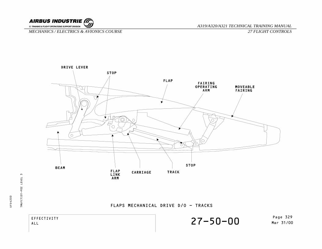
TMUFCTI01-P02 LEVEL 3
FLAPS MECHANICAL DRIVE D/O - TRACKS
EFFECTIVITY 27-50-00 Page 5Mar 31/00
_A319/A320/A321 TECHNICAL TRAINING MANUAL27 FLIGHT CONTROLSMECHANICS / ELECTRICS & AVIONICS COURSE
UFD4200
Page 329EFFECTIVITYALL
SELF EXAMINATION
Where are the Wing Tip Brakes located ?A - At the wing tipsB - Between tracks 3 and 4 in each wingC - Attached to track 4 offset gearbox
Where are the torque limiters located ?A - On the actuator offset gearboxB - On the actuator drive leverC - On the steady bearing
TMUFCTI01 LEVEL 3
EFFECTIVITY 27-50-00 Page 6Mar 31/00
_A319/A320/A321 TECHNICAL TRAINING MANUAL27 FLIGHT CONTROLSMECHANICS / ELECTRICS & AVIONICS COURSE
UFD4200
Page 330EFFECTIVITYALL

27 - FLIGHT CONTROLS
27-50-00 FLAPS MECHANICAL DRIVE D/O
CONTENTS:Power Control UnitTorque ShaftsGearboxesActuatorsTorque LimitersWing Tip BrakesAsymmetry PPUsTracksSelf Examination
TMUFCTI02 LEVEL 3
EFFECTIVITY 27-50-00 Page 1Mar 31/00
_A319/A320/A321 TECHNICAL TRAINING MANUAL27 FLIGHT CONTROLSMECHANICS / ELECTRICS & AVIONICS COURSE
UFD4200
Page 331EFFECTIVITYALL

FLAPS MECHANICAL DRIVE D/O
POWER CONTROL UNIT
The Power Control Unit incorporates two hydraulicmotors, each one controlled by an electrically signaledvalve block.The flap PCU drives the flap transmission outputshafts.
TORQUE SHAFTS
The rotation of the torque shafts drives all gearboxesand rotary actuator input shafts simultaneously, atthe same speed.Steady bearings, attached to the structure, supportthe torque shafts where small angular changes arepresent.
GEARBOXES
Three types of one to one ratio gearboxes are used inthe flap transmission where large changes in torqueshaft alignment are present.A right angle gearbox changes alignment through 90degrees for input to track 1 offset gearbox.A line gearbox moves drive path onto the rear face ofthe rear false spar.A 19 degree bevel gearbox aligns the drive with therear spar.
ACTUATORS
One actuator operates the flap mechanism at each track.It provides the torque and speed reduction necessaryto drive the flap at the required rate.Each actuator is driven by an offset gearbox whichtransmits power from the torque shaft to the plug-inrotary actuator.
TORQUE LIMITERS
Each actuator incorporates a bi-directional torquelimiter which protects the structure from overload.
WING TIP BRAKES
The Wing Tip Brakes (WTB) stop and hold thetransmission if the Slat Flap Control Computers detectabnormal operation such as asymmetry, runaway oroverspeed.Once applied, the Wing Tip Brakes can only be reseton the ground, by maintenance action via theCentralized Fault Display System (CFDS).
ASYMMETRY POSITION PICK OFF UNITS (APPUs)
The Asymmetry Position Pick off Units enable the SlatFlap Control Computers to monitor the system forasymmetry and runaway conditions.One Asymmetry Position Pick off Unit (APPU) is mountedon the offset gearbox at track 4 in each wing. Itprovides flap actual position to the Slat Flap ControlComputers (SFCC).
TMUFCTI02-T01 LEVEL 3
EFFECTIVITY 27-50-00 Page 2Mar 31/00
_A319/A320/A321 TECHNICAL TRAINING MANUAL27 FLIGHT CONTROLSMECHANICS / ELECTRICS & AVIONICS COURSE
UFD4200
Page 332EFFECTIVITYALL

FLAPS MECHANICAL DRIVE D/OTMUFCTI02-P01 LEVEL 3
EFFECTIVITY 27-50-00 Page 3Mar 31/00
_A319/A320/A321 TECHNICAL TRAINING MANUAL27 FLIGHT CONTROLSMECHANICS / ELECTRICS & AVIONICS COURSE
UFD4200
Page 333EFFECTIVITYALL

FLAPS MECHANICAL DRIVE D/O
TRACKS
Flaps are supported on carriages traveling on straighttracks. A link arm, outboard of each track, transmitsdrive from the actuator to the flap.Tracks 2, 3 and 4 are similar. Track 1, attached tothe fuselage, uses a different configuration.
TMUFCTI02-T02 LEVEL 3
EFFECTIVITY 27-50-00 Page 4Mar 31/00
_A319/A320/A321 TECHNICAL TRAINING MANUAL27 FLIGHT CONTROLSMECHANICS / ELECTRICS & AVIONICS COURSE
UFD4200
Page 334EFFECTIVITYALL
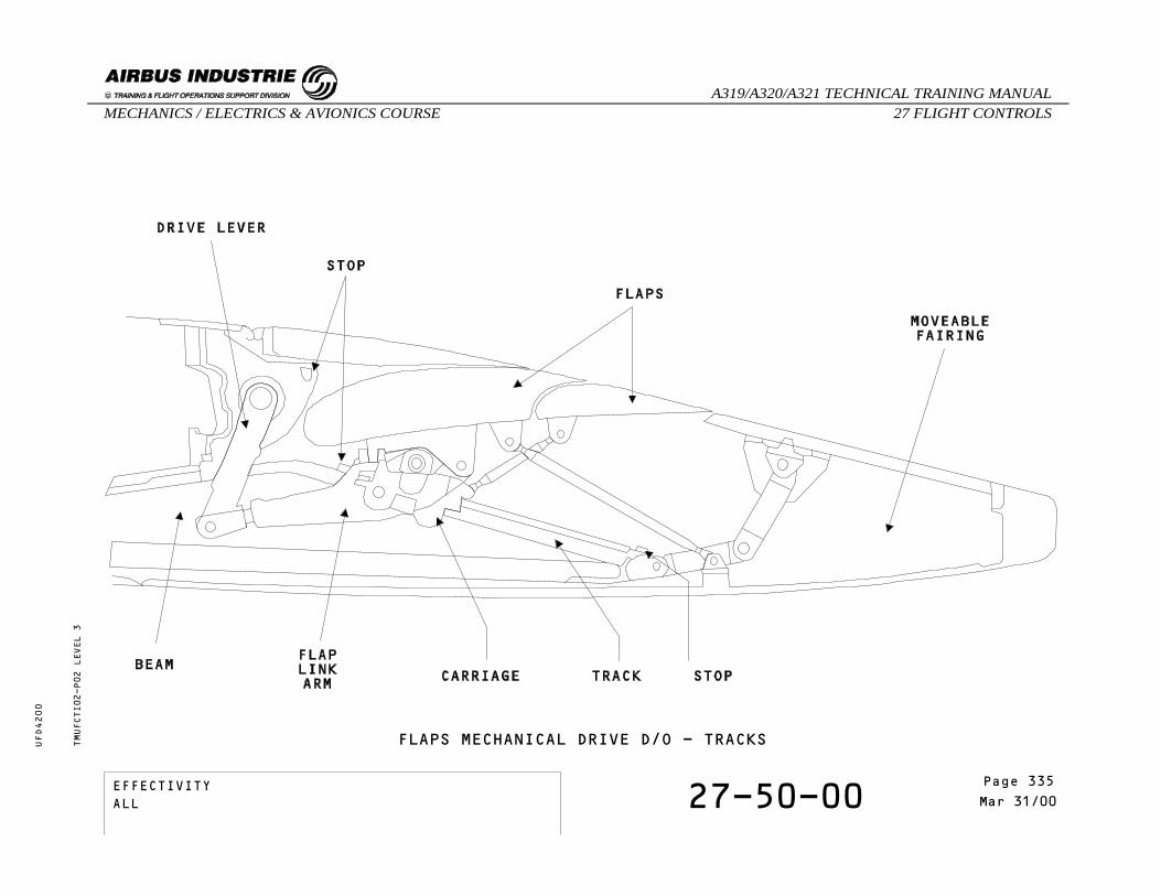
TMUFCTI02-P02 LEVEL 3
FLAPS MECHANICAL DRIVE D/O - TRACKS
EFFECTIVITY 27-50-00 Page 5Mar 31/00
_A319/A320/A321 TECHNICAL TRAINING MANUAL27 FLIGHT CONTROLSMECHANICS / ELECTRICS & AVIONICS COURSE
UFD4200
Page 335EFFECTIVITYALL

SELF EXAMINATION
Where are the Wing Tip Brakes located ?A - At the wing tipsB - Between tracks 3 and 4 in each wingC - Attached to track 4 offset gearbox
Where are the torque limiters located ?A - On the actuator offset gearboxB - On the actuator drive leverC - On the steady bearing
TMUFCTI02 LEVEL 3
EFFECTIVITY 27-50-00 Page 6Mar 31/00
_A319/A320/A321 TECHNICAL TRAINING MANUAL27 FLIGHT CONTROLSMECHANICS / ELECTRICS & AVIONICS COURSE
UFD4200
Page 336EFFECTIVITYALL
27 - FLIGHT CONTROLS
27-54-00 FLAPS DRIVE STATION D/O
CONTENTS:GeneralFlap DrivesFlap and Track FairingsSelf Examination
TMUFCBG02 LEVEL 3
EFFECTIVITY 27-54-00 Page 1Mar 31/00
_A319/A320/A321 TECHNICAL TRAINING MANUAL27 FLIGHT CONTROLSMECHANICS / ELECTRICS & AVIONICS COURSE
UFD4200
Page 337EFFECTIVITYALL

FLAPS DRIVE STATION D/O
GENERAL
Each flap is supported by carriages which run on tracksextending from the wing rear spar. Each carriage hasa containment device to hold it on the track if afailure occurs.The carriages, tracks and beams at tracks 2, 3 and 4are of similar construction. Track 1 is attached to the fuselage.
TMUFCBG02-T01 LEVEL 3
EFFECTIVITY 27-54-00 Page 2Mar 31/00
_A319/A320/A321 TECHNICAL TRAINING MANUAL27 FLIGHT CONTROLSMECHANICS / ELECTRICS & AVIONICS COURSE
UFD4200
Page 338EFFECTIVITYALL

FLAPS DRIVE STATION D/O - GENERAL
TMUFCBG02-P01 LEVEL 3
EFFECTIVITY 27-54-00 Page 3Mar 31/00
_A319/A320/A321 TECHNICAL TRAINING MANUAL27 FLIGHT CONTROLSMECHANICS / ELECTRICS & AVIONICS COURSE
UFD4200
Page 339EFFECTIVITYALL

FLAPS DRIVE STATION D/O
FLAP DRIVES
Carriage 1 is suspended below the track and travelson four vertical load and two side-load rollers.The rollers contain bearings which aregrease-lubricated via grease points on the carriage.
Carriages 2, 3 and 4 are retained on their track bysix vertical and four side-load rollers.The rollers are lubricated through grease points atthe front and rear of the carriage.A fail-safe hook retains the flap on the track in theevent of structural failure of the carriage.
TMUFCBG02-T02 LEVEL 3
EFFECTIVITY 27-54-00 Page 4Mar 31/00
_A319/A320/A321 TECHNICAL TRAINING MANUAL27 FLIGHT CONTROLSMECHANICS / ELECTRICS & AVIONICS COURSE
UFD4200
Page 340EFFECTIVITYALL

FLAPS DRIVE STATION D/O - FLAP DRIVES
TMUFCBG02-P02 LEVEL 3
EFFECTIVITY 27-54-00 Page 5Mar 31/00
_A319/A320/A321 TECHNICAL TRAINING MANUAL27 FLIGHT CONTROLSMECHANICS / ELECTRICS & AVIONICS COURSE
UFD4200
Page 341EFFECTIVITYALL

FLAPS DRIVE STATION D/O
FLAP AND TRACK FAIRINGS
A flap link arm is attached to the flap bottom surfaceimmediately outboard of each track position.The forward end of each link arm is bolted to the drivelever on its associated actuator. At tracks 2, 3 and 4 a track fairing operating arm isattached to the flap bottom surface. The operating arm is connected to a linkage whichoperates the moveable track fairing during flapextension and retraction.The link arms transmit the drive from the rotaryactuators directly to the flap surface.
TMUFCBG02-T03 LEVEL 3
EFFECTIVITY 27-54-00 Page 6Mar 31/00
_A319/A320/A321 TECHNICAL TRAINING MANUAL27 FLIGHT CONTROLSMECHANICS / ELECTRICS & AVIONICS COURSE
UFD4200
Page 342EFFECTIVITYALL

TMUFCBG02-P03 LEVEL 3
FLAPS DRIVE STATION D/O - FLAP AND TRACK FAIRINGS
EFFECTIVITY 27-54-00 Page 7Mar 31/00
_A319/A320/A321 TECHNICAL TRAINING MANUAL27 FLIGHT CONTROLSMECHANICS / ELECTRICS & AVIONICS COURSE
UFD4200
Page 343EFFECTIVITYALL

SELF EXAMINATION
How many rollers are there on carriages at tracks2, 3 and 4?
A - Six vertical-load and four side-loadrollers.
B - Four vertical-load and two side-loadrollers.
C - two vertical-load and four side-loadrollers.
TMUFCBG02 LEVEL 3
EFFECTIVITY 27-54-00 Page 8Mar 31/00
_A319/A320/A321 TECHNICAL TRAINING MANUAL27 FLIGHT CONTROLSMECHANICS / ELECTRICS & AVIONICS COURSE
UFD4200
Page 344EFFECTIVITYALL

27 - FLIGHT CONTROLS
27-51-00 FLAPS ATTACHMENT FAILUREDETECTION PRINCIPLE
CONTENTS:SensorsLanding Gear Control and Interface Units (LGCIUs)Slat Flap Control Computers (SFCCs)Self Examination
TMUFCTJ02 LEVEL 3
EFFECTIVITY 27-51-00 Page 1Mar 31/00
_A319/A320/A321 TECHNICAL TRAINING MANUAL27 FLIGHT CONTROLSMECHANICS / ELECTRICS & AVIONICS COURSE
UFD4200
Page 345EFFECTIVITYALL

FLAPS ATTACHMENT FAILURE DETECTION PRINCIPLE
SENSORS
Two flap disconnect sensors are fitted on theinterconnecting strut between inner and outer flapson each wing.The flap disconnect sensors, which are proximitysensors, detect any flap disconnection.
LANDING GEAR CONTROL and INTERFACE UNITS (LGCIUs)
Each Landing Gear Control Interface Unit (LGCIU)receives signals from two sensors and transmits thisdata to its related Slat/Flap Control Computer.The LGCIUs are used to process signals from proximitysensors.
SLAT FLAP CONTROL COMPUTERS (SFCCs)
Thanks to the computer cross talk, each Slat FlapControl Computer (SFCC) monitors any flapdisconnection.If an attachment failure has been detected by bothSFCCs, both valve block solenoids on the Power ControlUnit (PCU) are de-energized and the system is stoppedby the Pressure Off Brakes.In this case, the Wing Tip Brakes are not applied.
TMUFCTJ02-T01 LEVEL 3
EFFECTIVITY 27-51-00 Page 2Mar 31/00
_A319/A320/A321 TECHNICAL TRAINING MANUAL27 FLIGHT CONTROLSMECHANICS / ELECTRICS & AVIONICS COURSE
UFD4200
Page 346EFFECTIVITYALL

FLAPS ATTACHMENT FAILURE DETECTION PRINCIPLETMUFCTJ02-P01 LEVEL 3
EFFECTIVITY 27-51-00 Page 3Mar 31/00
_A319/A320/A321 TECHNICAL TRAINING MANUAL27 FLIGHT CONTROLSMECHANICS / ELECTRICS & AVIONICS COURSE
UFD4200
Page 347EFFECTIVITYALL

SELF EXAMINATION
Which computers monitor the flap disconnection data?A - The SFCCs which pass the information to
the LGCIUs.B - The LGCIUs which transmit the
information to the SFCCs.C - The LGCIUs only.
From which sensors does each LGCIU receiveinformation ?
A - All four disconnect sensors.B - One sensor on each wing.C - Two sensors on one wing.
TMUFCTJ02 LEVEL 3
EFFECTIVITY 27-51-00 Page 4Mar 31/00
_A319/A320/A321 TECHNICAL TRAINING MANUAL27 FLIGHT CONTROLSMECHANICS / ELECTRICS & AVIONICS COURSE
UFD4200
Page 348EFFECTIVITYALL

27 - FLIGHT CONTROLS
27-54-00 FLAP TRANSMISSION COMPONENTS
CONTENTS:Right Angle GearboxUniversal JointsSteady Bearing AssemblyTorque Shaft AssemblyCarriageLine GearboxActuatorsBevel Gearbox - 19°Torque LimitersFlap Track FairingWing Tip BrakeFlap Asymmetry Position Pick off Unit
TMUFCTN01 LEVEL 3
EFFECTIVITY 27-54-00 Page 1Oct 31/97
_A319/A320/A321 TECHNICAL TRAINING MANUAL27 FLIGHT CONTROLSMECHANICS / ELECTRICS & AVIONICS COURSE
UFD4200
Page 349EFFECTIVITYALL

FLAP TRANSMISSION COMPONENTS
RIGHT ANGLE GEARBOX
IDENTIFICATIONFIN: 6203CM, 6253CM
LOCATIONZONE: 147, 148
COMPONENT DESCRIPTIONThe gearbox has a 1.1 ratio. It is filled with grease.Lip seals on the input and output shafts prevent theingress of foreign matter.Inspection plugs are provided for maintenance.
UNIVERSAL JOINTS
COMPONENT DESCRIPTIONUniversal joints are bolted to the ends of the torqueshafts.This permits small angular changes of alignment, andwind flexing.
STEADY BEARING ASSEMBLY
COMPONENT DESCRIPTIONSteady bearings, attached to the structure, hold theshafts where necessary.
TMUFCTN01-T01 LEVEL 3
EFFECTIVITY 27-54-00 Page 2Oct 31/97
_A319/A320/A321 TECHNICAL TRAINING MANUAL27 FLIGHT CONTROLSMECHANICS / ELECTRICS & AVIONICS COURSE
UFD4200
Page 350EFFECTIVITYALL
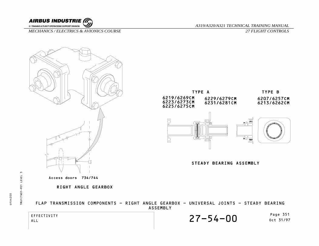
FLAP TRANSMISSION COMPONENTS - RIGHT ANGLE GEARBOX - UNIVERSAL JOINTS - STEADY BEARINGASSEMBLY
TMUFCTN01-P01 LEVEL 3
EFFECTIVITY 27-54-00 Page 3Oct 31/97
_A319/A320/A321 TECHNICAL TRAINING MANUAL27 FLIGHT CONTROLSMECHANICS / ELECTRICS & AVIONICS COURSE
UFD4200
Page 351EFFECTIVITYALL

FLAP TRANSMISSION COMPONENTS
TORQUE SHAFT ASSEMBLY
COMPONENT DESCRIPTIONThe torque shafts are connected through universaljoints and supported in steady bearings.They are made from stainless steel.
CARRIAGE
IDENTIFICATIONFIN: 6205CM, 6255CM
LOCATIONZONE: 147, 148
COMPONENT DESCRIPTIONThe carriage at track 1 hangs below the track andcomprises four vertical load and two side-load rollers.Six vertical and four side load rollers hold the othercarriages on their track.Each carriage incorporates a fail safe hook to preventflap detachment.
LINE GEARBOX
IDENTIFICATIONFIN: 6209CM, 6259CM
LOCATIONZONE: 573, 673
COMPONENT DESCRIPTIONThe LINE gearbox has a 1.1 ratio.Bearings, seals and methods of lubrication andinspection are the same as those used on the rightangle gearbox.
TMUFCTN01-T02 LEVEL 3
EFFECTIVITY 27-54-00 Page 4Oct 31/97
_A319/A320/A321 TECHNICAL TRAINING MANUAL27 FLIGHT CONTROLSMECHANICS / ELECTRICS & AVIONICS COURSE
UFD4200
Page 352EFFECTIVITYALL

FLAP TRANSMISSION COMPONENTS - TORQUE SHAFT ASSEMBLY - CARRIAGE - LINE GEARBOXTMUFCTN01-P02 LEVEL 3
EFFECTIVITY 27-54-00 Page 5Oct 31/97
_A319/A320/A321 TECHNICAL TRAINING MANUAL27 FLIGHT CONTROLSMECHANICS / ELECTRICS & AVIONICS COURSE
UFD4200
Page 353EFFECTIVITYALL

FLAP TRANSMISSION COMPONENTS
ACTUATORS
IDENTIFICATIONFIN: 6205CM, 6255CM
LOCATIONZONE: 147, 148
COMPONENT DESCRIPTIONA rotary actuator driven by an offset gearbox operatesthe flap mechanism at each flap track.Actuator at track 1:The rotary actuator is bolted to the offset gearboxcasing and is driven by its output shaft.Input torque from the offset gearbox is transmittedby a first stage gear train to the power stage of theactuator.Actuator at track 2:Similar to that described at T1 but a longer versionof rotary actuator is used.Actuator at track 3:Similar to actuator at T1 but bevel gears instead ofspur gears in the offset gearbox.Actuator at track 4:Similar to actuator at T1 but bevel gears instead ofspur gears are used in the offset gearbox which has aseparate spur gear to drive the APPU.
BEVEL GEARBOX - 19 DEGREES
IDENTIFICATIONFIN: 6217CM, 6267CM
LOCATIONZONE: 575, 675
COMPONENT DESCRIPTIONThe bevel gearbox has a 1.1 ratio.Bearings, seals and methods of lubrication andinspection are the same as those used on the rightangle gearbox.
TMUFCTN01-T03 LEVEL 3
EFFECTIVITY 27-54-00 Page 6Oct 31/97
_A319/A320/A321 TECHNICAL TRAINING MANUAL27 FLIGHT CONTROLSMECHANICS / ELECTRICS & AVIONICS COURSE
UFD4200
Page 354EFFECTIVITYALL
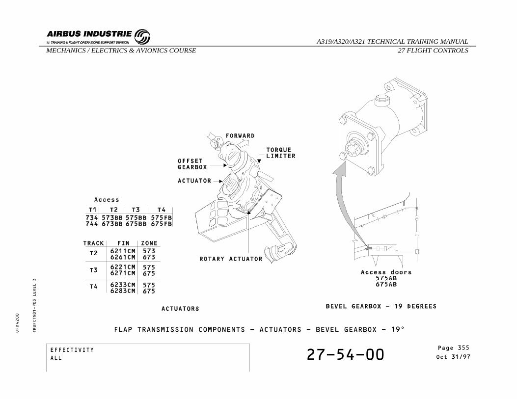
FLAP TRANSMISSION COMPONENTS - ACTUATORS - BEVEL GEARBOX - 19°TMUFCTN01-P03 LEVEL 3
EFFECTIVITY 27-54-00 Page 7Oct 31/97
_A319/A320/A321 TECHNICAL TRAINING MANUAL27 FLIGHT CONTROLSMECHANICS / ELECTRICS & AVIONICS COURSE
UFD4200
Page 355EFFECTIVITYALL

FLAP TRANSMISSION COMPONENTS
TORQUE LIMITERS
COMPONENT DESCRIPTIONA bi-directional torque limiter is incorporated in thetransmission input of each actuator.A latching mechanical indicator shows if a lock outtorque has occurred.
FLAP TRACK FAIRING
COMPONENT DESCRIPTIONA flap link arm is attached to the bottom flap surfaceoutboard of each track and transmits the drive fromthe actuator directly to the flap.Attached to the flap bottom, at tracks 2,3 and 4, isan arm which operates the moveable track fairing duringflap movement.
TMUFCTN01-T04 LEVEL 3
EFFECTIVITY 27-54-00 Page 8Oct 31/97
_A319/A320/A321 TECHNICAL TRAINING MANUAL27 FLIGHT CONTROLSMECHANICS / ELECTRICS & AVIONICS COURSE
UFD4200
Page 356EFFECTIVITYALL
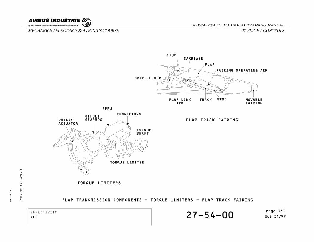
TMUFCTN01-P04 LEVEL 3
FLAP TRANSMISSION COMPONENTS - TORQUE LIMITERS - FLAP TRACK FAIRING
EFFECTIVITY 27-54-00 Page 9Oct 31/97
_A319/A320/A321 TECHNICAL TRAINING MANUAL27 FLIGHT CONTROLSMECHANICS / ELECTRICS & AVIONICS COURSE
UFD4200
Page 357EFFECTIVITYALL

FLAP TRANSMISSION COMPONENTS
WING TIP BRAKE
IDENTIFICATIONFIN: 33CV, 34CV
LOCATIONZONE: 575, 675
COMPONENT DESCRIPTIONIf pressure is not available to one piston, the otherpiston provides sufficient torque to stop and hold thetorque shaft.Access: 575EB/675EB between T3 and T4.
FLAP ASYMMETRY POSITION PICK OFF UNIT
IDENTIFICATIONFIN: 29CV, 30CV
LOCATIONZONE: 575, 675
COMPONENT DESCRIPTIONOne Asymmetry Position Pick off Unit (APPU) is locatedat the end of the transmission system in each wing.They are identical to and interchangeable with theFeedback Position Pick off Unit (FPPU) and theInstrument Position Pick off Unit (IPPU).Access: 575FB/675FB.
TMUFCTN01-T05 LEVEL 3
EFFECTIVITY 27-54-00 Page 10Oct 31/97
_A319/A320/A321 TECHNICAL TRAINING MANUAL27 FLIGHT CONTROLSMECHANICS / ELECTRICS & AVIONICS COURSE
UFD4200
Page 358EFFECTIVITYALL

FLAP TRANSMISSION COMPONENTS - WING TIP BRAKE - FLAP APPUTMUFCTN01-P05 LEVEL 3
EFFECTIVITY 27-54-00 Page 11Oct 31/97
_A319/A320/A321 TECHNICAL TRAINING MANUAL27 FLIGHT CONTROLSMECHANICS / ELECTRICS & AVIONICS COURSE
UFD4200
Page 359EFFECTIVITYALL

THIS PAGE INTENTIONALLY LEFT BLANK
TMUFCTN01 LEVEL 3
EFFECTIVITY 27-54-00 Page 12Oct 31/97
_A319/A320/A321 TECHNICAL TRAINING MANUAL27 FLIGHT CONTROLSMECHANICS / ELECTRICS & AVIONICS COURSE
UFD4200
Page 360EFFECTIVITYALL

27 - FLIGHT CONTROLS
27-84-00 SLAT TRANSMISSION COMPONENTS
CONTENTS:Bevel Gearbox - 19°T GearboxUniversal JointsSteady Bearing AssemblyTorque ShaftsBevel Gearbox - 63.5°ActuatorsTorque LimitersSlat Track InstallationWing Tip BrakesAsymmetry Position Pick Off Units
TMUFCTP01 LEVEL 3
EFFECTIVITY 27-84-00 Page 1Oct 31/97
_A319/A320/A321 TECHNICAL TRAINING MANUAL27 FLIGHT CONTROLSMECHANICS / ELECTRICS & AVIONICS COURSE
UFD4200
Page 361EFFECTIVITYALL

SLAT TRANSMISSION COMPONENTS
BEVEL GEARBOX - 19°
IDENTIFICATIONFIN: 6003CM
LOCATIONZONE: 191
COMPONENT DESCRIPTIONThe bevel gearbox has a 1:1 ratio.It is pre-packed with grease and incorporates unsealedstainless bearings.Inspection plugs are provided for on conditionmaintenance.
T GEARBOX
IDENTIFICATIONFIN: 6005CM
LOCATIONZONE: 191
COMPONENT DESCRIPTIONThe gearbox has a 1:1 ratio.Bearings, seals, and methods of lubrication andinspection are similar to those used on the 19° bevelgearbox.
UNIVERSAL JOINTS
COMPONENT DESCRIPTIONUniversal joints are bolted to the ends of the torqueshafts.This permits small angular changes of alignment andwing flexing.
TMUFCTP01-T01 LEVEL 3
EFFECTIVITY 27-84-00 Page 2Oct 31/97
_A319/A320/A321 TECHNICAL TRAINING MANUAL27 FLIGHT CONTROLSMECHANICS / ELECTRICS & AVIONICS COURSE
UFD4200
Page 362EFFECTIVITYALL

SLAT TRANSMISSION COMPONENTS - 19° BEVEL GEARBOX - T GEARBOX - UNIVERSAL JOINTSTMUFCTP01-P01 LEVEL 3
EFFECTIVITY 27-84-00 Page 3Oct 31/97
_A319/A320/A321 TECHNICAL TRAINING MANUAL27 FLIGHT CONTROLSMECHANICS / ELECTRICS & AVIONICS COURSE
UFD4200
Page 363EFFECTIVITYALL

SLAT TRANSMISSION COMPONENTS
STEADY BEARING ASSEMBLY
COMPONENT DESCRIPTIONSteady bearings, attached to the structure, hold theshafts where small angular changes of alignment arepresent.
TORQUE SHAFTS
COMPONENT DESCRIPTIONThe torque shaft made from stainless steel areconnected through universal joints and supported insteady bearings.6012CM, 6062CM, 6024CM, 6074CM, 6034CM, 6084CM havean additional flanged joint at the middle point of theshaft.
BEVEL GEARBOX 63.5°
IDENTIFICATIONFIN: 6009CM, 6059CM, 6011CM, 6061CM
LOCATIONZONE: 191, 192
COMPONENT DESCRIPTIONThere are four 63.5 degree bevel gearboxes.Bearings, seals and methods of lubrication andinspection are the same as those used on the 19 degreesbevel gearbox.
TMUFCTP01-T02 LEVEL 3
EFFECTIVITY 27-84-00 Page 4Oct 31/97
_A319/A320/A321 TECHNICAL TRAINING MANUAL27 FLIGHT CONTROLSMECHANICS / ELECTRICS & AVIONICS COURSE
UFD4200
Page 364EFFECTIVITYALL

SLAT TRANSMISSION COMPONENTS - STEADY BEARING ASSEMBLY - TORQUE SHAFTS -63.5º BEVEL GEARBOX
TMUFCTP01-P02 LEVEL 3
EFFECTIVITY 27-84-00 Page 5Oct 31/97
_A319/A320/A321 TECHNICAL TRAINING MANUAL27 FLIGHT CONTROLSMECHANICS / ELECTRICS & AVIONICS COURSE
UFD4200
Page 365EFFECTIVITYALL

SLAT TRANSMISSION COMPONENTS
ACTUATORS
IDENTIFICATIONFIN: 6013CM, 6063CM
LOCATIONZONE: 521, 621
COMPONENT DESCRIPTIONTwo sizes of actuators are used.The large diameter ones at T2 and T3 incorporateadditional gearing but construction and operation issimilar for all actuators.They are pre-packed with grease for "life time"lubrication.Vent holes are provided in the casing for drainage ofany accumulated moisture.
TORQUE LIMITERS
IDENTIFICATIONFIN: 6013CM, 6063CM
LOCATIONZONE: 521, 621
COMPONENT DESCRIPTIONEach actuator incorporates a bi-directional torquelimiter which prevents excessive torque beingtransmitted to the output.A latching mechanical indicator is provided to showwhen lock-out torque has occurred.The mechanism may be reset by reverse operation butthe indicator remains extended until cancelledmanually.
TMUFCTP01-T03 LEVEL 3
EFFECTIVITY 27-84-00 Page 6Oct 31/97
_A319/A320/A321 TECHNICAL TRAINING MANUAL27 FLIGHT CONTROLSMECHANICS / ELECTRICS & AVIONICS COURSE
UFD4200
Page 366EFFECTIVITYALL

SLAT TRANSMISSION COMPONENTS - ACTUATORS - TORQUE LIMITERSTMUFCTP01-P03 LEVEL 3
EFFECTIVITY 27-84-00 Page 7Oct 31/97
_A319/A320/A321 TECHNICAL TRAINING MANUAL27 FLIGHT CONTROLSMECHANICS / ELECTRICS & AVIONICS COURSE
UFD4200
Page 367EFFECTIVITYALL
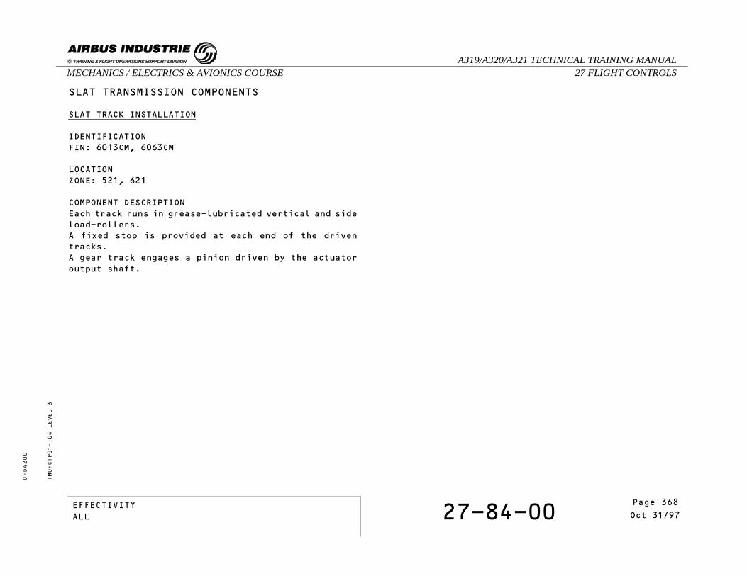
SLAT TRANSMISSION COMPONENTS
SLAT TRACK INSTALLATION
IDENTIFICATIONFIN: 6013CM, 6063CM
LOCATIONZONE: 521, 621
COMPONENT DESCRIPTIONEach track runs in grease-lubricated vertical and sideload-rollers.A fixed stop is provided at each end of the driventracks.A gear track engages a pinion driven by the actuatoroutput shaft.
TMUFCTP01-T04 LEVEL 3
EFFECTIVITY 27-84-00 Page 8Oct 31/97
_A319/A320/A321 TECHNICAL TRAINING MANUAL27 FLIGHT CONTROLSMECHANICS / ELECTRICS & AVIONICS COURSE
UFD4200
Page 368EFFECTIVITYALL

SLAT TRANSMISSION COMPONENTS - SLAT TRACK INSTALLATIONTMUFCTP01-P04 LEVEL 3
EFFECTIVITY 27-84-00 Page 9Oct 31/97
_A319/A320/A321 TECHNICAL TRAINING MANUAL27 FLIGHT CONTROLSMECHANICS / ELECTRICS & AVIONICS COURSE
UFD4200
Page 369EFFECTIVITYALL
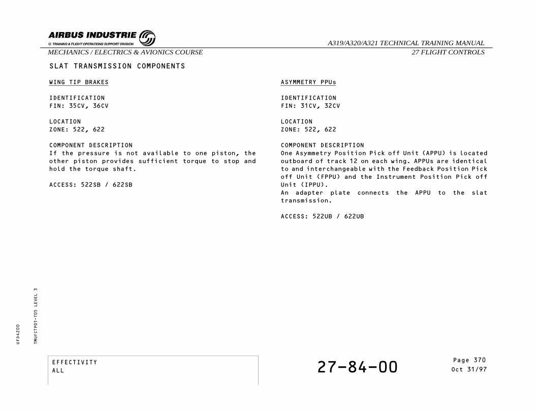
SLAT TRANSMISSION COMPONENTS
WING TIP BRAKES
IDENTIFICATIONFIN: 35CV, 36CV
LOCATIONZONE: 522, 622
COMPONENT DESCRIPTIONIf the pressure is not available to one piston, theother piston provides sufficient torque to stop andhold the torque shaft.
ACCESS: 522SB / 622SB
ASYMMETRY PPUs
IDENTIFICATIONFIN: 31CV, 32CV
LOCATIONZONE: 522, 622
COMPONENT DESCRIPTIONOne Asymmetry Position Pick off Unit (APPU) is locatedoutboard of track 12 on each wing. APPUs are identicalto and interchangeable with the Feedback Position Pickoff Unit (FPPU) and the Instrument Position Pick offUnit (IPPU).An adapter plate connects the APPU to the slattransmission.
ACCESS: 522UB / 622UB
TMUFCTP01-T05 LEVEL 3
EFFECTIVITY 27-84-00 Page 10Oct 31/97
_A319/A320/A321 TECHNICAL TRAINING MANUAL27 FLIGHT CONTROLSMECHANICS / ELECTRICS & AVIONICS COURSE
UFD4200
Page 370EFFECTIVITYALL

SLAT TRANSMISSION COMPONENTS - WING TIP BRAKES - ASYMMETRY PPUsTMUFCTP01-P05 LEVEL 3
EFFECTIVITY 27-84-00 Page 11Oct 31/97
_A319/A320/A321 TECHNICAL TRAINING MANUAL27 FLIGHT CONTROLSMECHANICS / ELECTRICS & AVIONICS COURSE
UFD4200
Page 371EFFECTIVITYALL

THIS PAGE INTENTIONALLY LEFT BLANK
TMUFCTP01 LEVEL 3
EFFECTIVITY 27-84-00 Page 12Oct 31/97
_A319/A320/A321 TECHNICAL TRAINING MANUAL27 FLIGHT CONTROLSMECHANICS / ELECTRICS & AVIONICS COURSE
UFD4200
Page 372EFFECTIVITYALL

27 - FLIGHT CONTROLS
27-51-00 SLATS/FLAPS CONTROL ANDMONITORING COMPONENTS
CONTENTS:Slats/Flaps Control Lever and Command Sensor UnitSlats/Flaps Control ComputersFlap Disconnect Sensors
TMUFCTS01 LEVEL 3
EFFECTIVITY 27-51-00 Page 1Mar 31/00
_A319/A320/A321 TECHNICAL TRAINING MANUAL27 FLIGHT CONTROLSMECHANICS / ELECTRICS & AVIONICS COURSE
UFD4200
Page 373EFFECTIVITYALL

SLATS/FLAPS CONTROL AND MONITORING COMPONENTS
SLATS/FLAPS CONTROL LEVER AND COMMAND SENSOR UNIT
IDENTIFICATIONFIN: 51CV
LOCATIONZONE: 220
SLATS/FLAPS CONTROL COMPUTERS
IDENTIFICATIONFIN: 21CV, 22CV
LOCATIONZONE: 127, 128
COMPONENT DESCRIPTIONSlat Flap Control System (SFCS) no2 flap channel maybe inoperative provided:
- Slats, Flaps and associated monitoring andprotection systems are fully operable on SFCS1 and
- Operation of SFCS 1 Wing Tip Brakes areconfirmed by test before each flight and
- all ELAC, SEC, LGCIU, RA, FAC and ADIRS areoperative.
NOTE: Minimum idle on ground function is inoperative.Refer to 73-20-07
TMUFCTS01-T01 LEVEL 3
EFFECTIVITY 27-51-00 Page 2Mar 31/00
_A319/A320/A321 TECHNICAL TRAINING MANUAL27 FLIGHT CONTROLSMECHANICS / ELECTRICS & AVIONICS COURSE
UFD4200
Page 374EFFECTIVITYALL
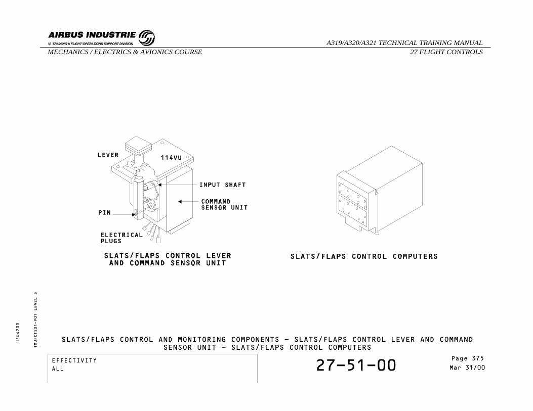
SLATS/FLAPS CONTROL AND MONITORING COMPONENTS - SLATS/FLAPS CONTROL LEVER AND COMMANDSENSOR UNIT - SLATS/FLAPS CONTROL COMPUTERST
MUFCTS01-P01 LEVEL 3
EFFECTIVITY 27-51-00 Page 3Mar 31/00
_A319/A320/A321 TECHNICAL TRAINING MANUAL27 FLIGHT CONTROLSMECHANICS / ELECTRICS & AVIONICS COURSE
UFD4200
Page 375EFFECTIVITYALL

SLATS/FLAPS CONTROL AND MONITORING COMPONENTS
FLAP DISCONNECT SENSORS
IDENTIFICATIONFIN: 38CV, 40CV, 37CV, 39CV
LOCATIONZONE: 680, 580
COMPONENT DESCRIPTIONTwo flap disconnect sensors (on each wing) are fittedon the interconnecting strut between inner and outerflaps.The flap disconnect sensors, which are proximitysensors, detect any flap disconnection.
TMUFCTS01-T02 LEVEL 3
EFFECTIVITY 27-51-00 Page 4Mar 31/00
_A319/A320/A321 TECHNICAL TRAINING MANUAL27 FLIGHT CONTROLSMECHANICS / ELECTRICS & AVIONICS COURSE
UFD4200
Page 376EFFECTIVITYALL

SLATS/FLAPS CONTROL AND MONITORING COMPONENTS - FLAP DISCONNECT SENSORS
TMUFCTS01-P02 LEVEL 3
EFFECTIVITY 27-51-00 Page 5Mar 31/00
_A319/A320/A321 TECHNICAL TRAINING MANUAL27 FLIGHT CONTROLSMECHANICS / ELECTRICS & AVIONICS COURSE
UFD4200
Page 377EFFECTIVITYALL

THIS PAGE INTENTIONALLY LEFT BLANK
TMUFCTS01 LEVEL 3
EFFECTIVITY 27-51-00 Page 6Mar 31/00
_A319/A320/A321 TECHNICAL TRAINING MANUAL27 FLIGHT CONTROLSMECHANICS / ELECTRICS & AVIONICS COURSE
UFD4200
Page 378EFFECTIVITYALL

27 - FLIGHT CONTROLS
27-54-00 FLAPS POWER CONTROL UNITCOMPONENTS
CONTENTS:Valve BlocksHydraulic MotorsPressure Off BrakesPosition Pick Off Units
TMUFCTR01 LEVEL 3
EFFECTIVITY 27-54-00 Page 1Oct 31/97
_A319/A320/A321 TECHNICAL TRAINING MANUAL27 FLIGHT CONTROLSMECHANICS / ELECTRICS & AVIONICS COURSE
UFD4200
Page 379EFFECTIVITYALL
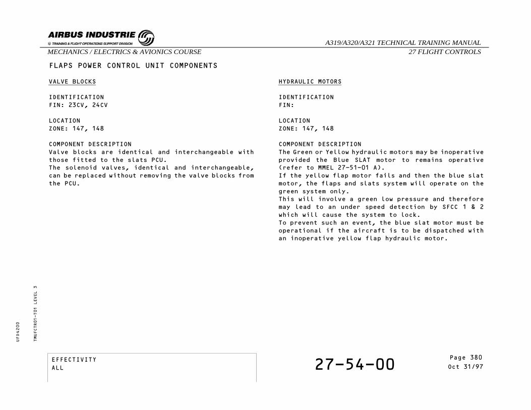
FLAPS POWER CONTROL UNIT COMPONENTS
VALVE BLOCKS
IDENTIFICATIONFIN: 23CV, 24CV
LOCATIONZONE: 147, 148
COMPONENT DESCRIPTIONValve blocks are identical and interchangeable withthose fitted to the slats PCU.The solenoid valves, identical and interchangeable,can be replaced without removing the valve blocks fromthe PCU.
HYDRAULIC MOTORS
IDENTIFICATIONFIN:
LOCATIONZONE: 147, 148
COMPONENT DESCRIPTIONThe Green or Yellow hydraulic motors may be inoperativeprovided the Blue SLAT motor to remains operative(refer to MMEL 27-51-01 A).If the yellow flap motor fails and then the blue slatmotor, the flaps and slats system will operate on thegreen system only.This will involve a green low pressure and thereforemay lead to an under speed detection by SFCC 1 & 2which will cause the system to lock.To prevent such an event, the blue slat motor must beoperational if the aircraft is to be dispatched withan inoperative yellow flap hydraulic motor.
TMUFCTR01-T01 LEVEL 3
EFFECTIVITY 27-54-00 Page 2Oct 31/97
_A319/A320/A321 TECHNICAL TRAINING MANUAL27 FLIGHT CONTROLSMECHANICS / ELECTRICS & AVIONICS COURSE
UFD4200
Page 380EFFECTIVITYALL

TMUFCTR01-P01 LEVEL 3
FLAPS POWER CONTROL UNIT COMPONENTS - VALVE BLOCKS - HYDRAULIC MOTORS - PRESSURE OFFBRAKES - POSITION PICK OFF UNITS
EFFECTIVITY 27-54-00 Page 3Oct 31/97
_A319/A320/A321 TECHNICAL TRAINING MANUAL27 FLIGHT CONTROLSMECHANICS / ELECTRICS & AVIONICS COURSE
UFD4200
Page 381EFFECTIVITYALL

FLAPS POWER CONTROL UNIT COMPONENTS
PRESSURE OFF BRAKES
IDENTIFICATIONFIN:
LOCATIONZONE: 147, 148
COMPONENT DESCRIPTIONTo replace the Pressure Off Brake, the associatedhydraulic motor must be removed first.They are identical to those installed on the slatsPCU.
POSITION PICK OFF UNITS
IDENTIFICATIONFIN: 3CN, 27CV
LOCATIONZONE: 147, 148
COMPONENT DESCRIPTIONThe IPPU and FPPU are identical to those fitted on theslats PCU.They are identical and interchangeable with the APPUand can be replaced without removing the PCU from theA/C.
TMUFCTR01-T01 LEVEL 3
EFFECTIVITY 27-54-00 Page 4Oct 31/97
_A319/A320/A321 TECHNICAL TRAINING MANUAL27 FLIGHT CONTROLSMECHANICS / ELECTRICS & AVIONICS COURSE
UFD4200
Page 382EFFECTIVITYALL
27 - FLIGHT CONTROLS
27-84-00 SLATS POWER CONTROL UNITCOMPONENTS
CONTENTS:PCU Valve BlocksPCU Hydraulic MotorsPressure Off BrakesInstrument Position Pick Off Units / Feedback PositionPick Off Units
TMUFCTT01 LEVEL 3
EFFECTIVITY 27-84-00 Page 1Mar 31/00
_A319/A320/A321 TECHNICAL TRAINING MANUAL27 FLIGHT CONTROLSMECHANICS / ELECTRICS & AVIONICS COURSE
UFD4200
Page 383EFFECTIVITYALL
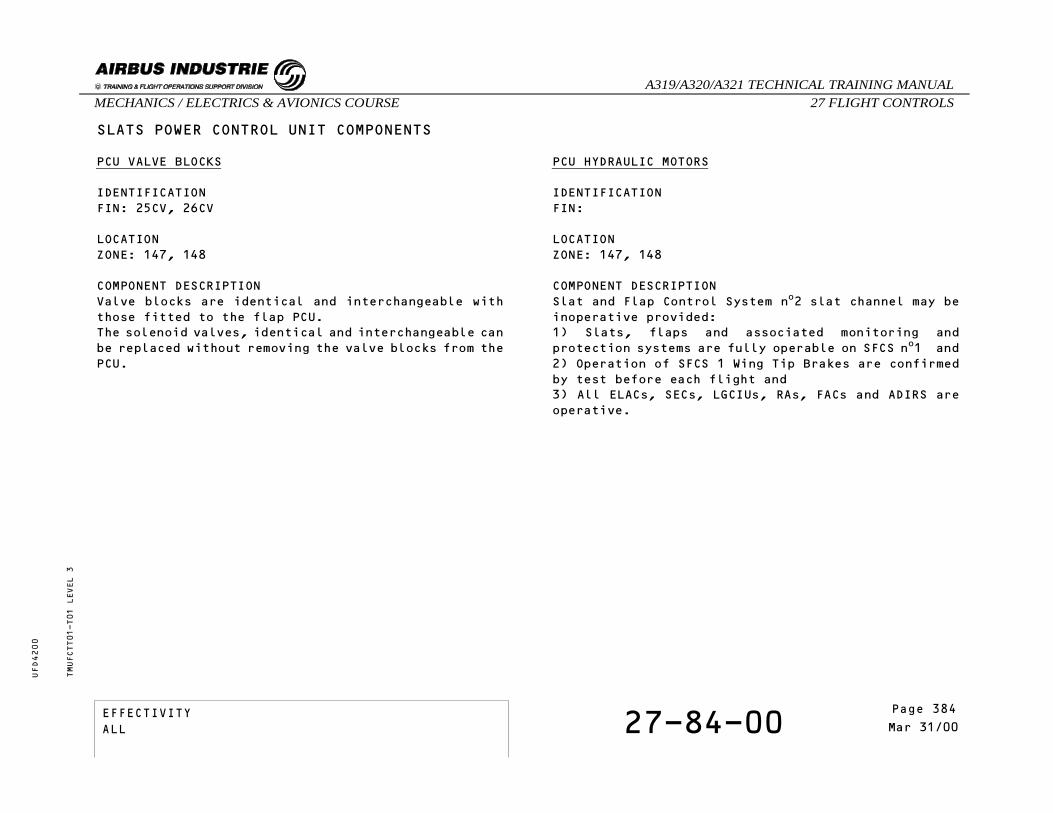
SLATS POWER CONTROL UNIT COMPONENTS
PCU VALVE BLOCKS
IDENTIFICATIONFIN: 25CV, 26CV
LOCATIONZONE: 147, 148
COMPONENT DESCRIPTIONValve blocks are identical and interchangeable withthose fitted to the flap PCU.The solenoid valves, identical and interchangeable canbe replaced without removing the valve blocks from thePCU.
PCU HYDRAULIC MOTORS
IDENTIFICATIONFIN:
LOCATIONZONE: 147, 148
COMPONENT DESCRIPTIONSlat and Flap Control System no2 slat channel may beinoperative provided:1) Slats, flaps and associated monitoring andprotection systems are fully operable on SFCS no1 and2) Operation of SFCS 1 Wing Tip Brakes are confirmedby test before each flight and3) All ELACs, SECs, LGCIUs, RAs, FACs and ADIRS areoperative.
TMUFCTT01-T01 LEVEL 3
EFFECTIVITY 27-84-00 Page 2Mar 31/00
_A319/A320/A321 TECHNICAL TRAINING MANUAL27 FLIGHT CONTROLSMECHANICS / ELECTRICS & AVIONICS COURSE
UFD4200
Page 384EFFECTIVITYALL
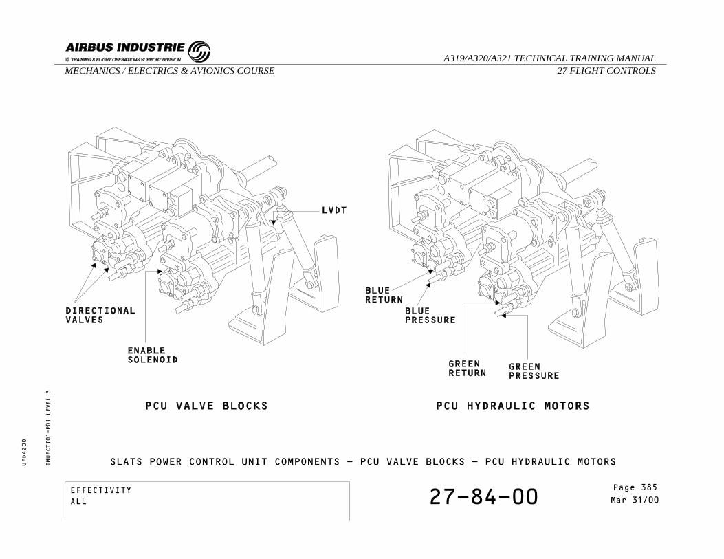
SLATS POWER CONTROL UNIT COMPONENTS - PCU VALVE BLOCKS - PCU HYDRAULIC MOTORSTMUFCTT01-P01 LEVEL 3
EFFECTIVITY 27-84-00 Page 3Mar 31/00
_A319/A320/A321 TECHNICAL TRAINING MANUAL27 FLIGHT CONTROLSMECHANICS / ELECTRICS & AVIONICS COURSE
UFD4200
Page 385EFFECTIVITYALL

SLATS POWER CONTROL UNIT COMPONENTS
PRESSURE OFF BRAKES
IDENTIFICATIONFIN:
LOCATIONZONE: 147, 148
COMPONENT DESCRIPTIONTo replace the POB, the associated motor must beremoved first.
Instrument Position Pick Off Units / Feedback PositionPick Off Units
IDENTIFICATIONFIN: 4CN, 28CV
LOCATIONZONE: 147, 148
COMPONENT DESCRIPTIONThe IPPU and FPPU are identical and interchangeablewith the APPU and can be replaced without removing thePCU.They are identical to those fitted on the flap PCU.
TMUFCTT01-T02 LEVEL 3
EFFECTIVITY 27-84-00 Page 4Mar 31/00
_A319/A320/A321 TECHNICAL TRAINING MANUAL27 FLIGHT CONTROLSMECHANICS / ELECTRICS & AVIONICS COURSE
UFD4200
Page 386EFFECTIVITYALL
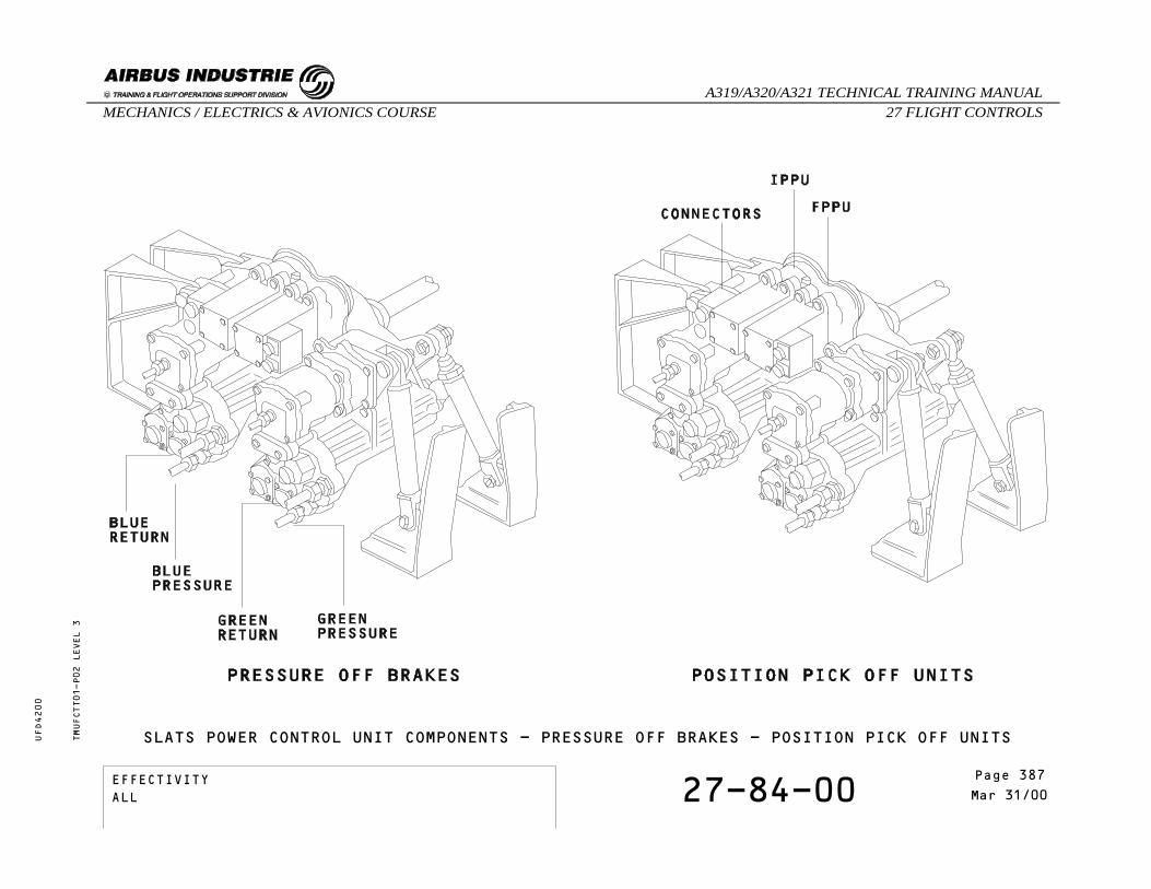
TMUFCTT01-P02 LEVEL 3
SLATS POWER CONTROL UNIT COMPONENTS - PRESSURE OFF BRAKES - POSITION PICK OFF UNITS
EFFECTIVITY 27-84-00 Page 5Mar 31/00
_A319/A320/A321 TECHNICAL TRAINING MANUAL27 FLIGHT CONTROLSMECHANICS / ELECTRICS & AVIONICS COURSE
UFD4200
Page 387EFFECTIVITYALL

THIS PAGE INTENTIONALLY LEFT BLANK
TMUFCTT01 LEVEL 3
EFFECTIVITY 27-84-00 Page 6Mar 31/00
_A319/A320/A321 TECHNICAL TRAINING MANUAL27 FLIGHT CONTROLSMECHANICS / ELECTRICS & AVIONICS COURSE
UFD4200
Page 388EFFECTIVITYALL

27 - FLIGHT CONTROLS
27-00-00 SLATS/FLAPS WARNINGS
CONTENTS:Slats/Flaps FaultSlats/Flaps Locked
TMUFC1701 LEVEL 3
EFFECTIVITY 27-00-00 Page 1Mar 31/00
_A319/A320/A321 TECHNICAL TRAINING MANUAL27 FLIGHT CONTROLSMECHANICS / ELECTRICS & AVIONICS COURSE
UFD4200
Page 389EFFECTIVITYALL

SLATS/FLAPS WARNINGS
SLATS/FLAPS FAULT
The present configuration is position 2 in flight.In case of slat or flap fault, the MASTER CAUTION comeson, an aural warning sounds and the word FLAP becomesamber.The failure is displayed on the ECAM page.In this example, the selected flap position has notbeen reached, the position number and the triangleremain cyan and the green line turns to amber.
TMUFC1701-T01 LEVEL 3
EFFECTIVITY 27-00-00 Page 2Mar 31/00
_A319/A320/A321 TECHNICAL TRAINING MANUAL27 FLIGHT CONTROLSMECHANICS / ELECTRICS & AVIONICS COURSE
UFD4200
Page 390EFFECTIVITYALL

SLATS/FLAPS WARNINGS - SLATS/FLAPS FAULTTMUFC1701-P01 LEVEL 3
EFFECTIVITY 27-00-00 Page 3Mar 31/00
_A319/A320/A321 TECHNICAL TRAINING MANUAL27 FLIGHT CONTROLSMECHANICS / ELECTRICS & AVIONICS COURSE
UFD4200
Page 391EFFECTIVITYALL

SLATS/FLAPS WARNINGS
SLATS/FLAPS LOCKED
The present configuration is 3 position.In case of locked slat or flap, the MASTER CAUTIONcomes on, an aural warning sounds and the word FLAPbecomes amber.The failure is displayed on the ECAM page.In this example, the selected slat position has notbeen reached, the position number and the triangleremain cyan and the green line turns to amber.
TMUFC1701-T02 LEVEL 3
EFFECTIVITY 27-00-00 Page 4Mar 31/00
_A319/A320/A321 TECHNICAL TRAINING MANUAL27 FLIGHT CONTROLSMECHANICS / ELECTRICS & AVIONICS COURSE
UFD4200
Page 392EFFECTIVITYALL

SLATS/FLAPS WARNINGS - SLATS/FLAPS LOCKEDTMUFC1701-P02 LEVEL 3
EFFECTIVITY 27-00-00 Page 5Mar 31/00
_A319/A320/A321 TECHNICAL TRAINING MANUAL27 FLIGHT CONTROLSMECHANICS / ELECTRICS & AVIONICS COURSE
UFD4200
Page 393EFFECTIVITYALL

THIS PAGE INTENTIONALLY LEFT BLANK
TMUFC1701 LEVEL 3
EFFECTIVITY 27-00-00 Page 6Mar 31/00
_A319/A320/A321 TECHNICAL TRAINING MANUAL27 FLIGHT CONTROLSMECHANICS / ELECTRICS & AVIONICS COURSE
UFD4200
Page 394EFFECTIVITYALL

27 - FLIGHT CONTROLS
27-00-00 SLAT FLAP CONTROL COMPUTERCONTROL INTERFACES
CONTENTS:Command Sensor Unit (CSU)LH and RH Asymmetry Position Pick off Units (APPUs)Feedback Position Pick off Units (FPPU)LH and RH Wing Tip BrakesPower Control Unit (PCU)Air Data/Inertial Reference Units (ADIRUs)Landing Gear and Control Interface Units 1 and 2(LGCIU1 and 2)Centralized Fault and Display Interface Unit (CFDIU)
TMUFCTF02 LEVEL 3
EFFECTIVITY 27-00-00 Page 1May 31/00
_A319/A320/A321 TECHNICAL TRAINING MANUAL27 FLIGHT CONTROLSMECHANICS / ELECTRICS & AVIONICS COURSE
UFD4200
Page 395EFFECTIVITYALL
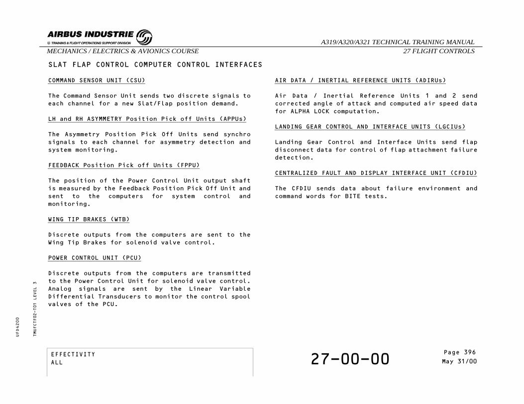
SLAT FLAP CONTROL COMPUTER CONTROL INTERFACES
COMMAND SENSOR UNIT (CSU)
The Command Sensor Unit sends two discrete signals toeach channel for a new Slat/Flap position demand.
LH and RH ASYMMETRY Position Pick off Units (APPUs)
The Asymmetry Position Pick Off Units send synchrosignals to each channel for asymmetry detection andsystem monitoring.
FEEDBACK Position Pick off Units (FPPU)
The position of the Power Control Unit output shaftis measured by the Feedback Position Pick Off Unit andsent to the computers for system control andmonitoring.
WING TIP BRAKES (WTB)
Discrete outputs from the computers are sent to theWing Tip Brakes for solenoid valve control.
POWER CONTROL UNIT (PCU)
Discrete outputs from the computers are transmittedto the Power Control Unit for solenoid valve control.Analog signals are sent by the Linear VariableDifferential Transducers to monitor the control spoolvalves of the PCU.
AIR DATA / INERTIAL REFERENCE UNITS (ADIRUs)
Air Data / Inertial Reference Units 1 and 2 sendcorrected angle of attack and computed air speed datafor ALPHA LOCK computation.
LANDING GEAR CONTROL AND INTERFACE UNITS (LGCIUs)
Landing Gear Control and Interface Units send flapdisconnect data for control of flap attachment failuredetection.
CENTRALIZED FAULT AND DISPLAY INTERFACE UNIT (CFDIU)
The CFDIU sends data about failure environment andcommand words for BITE tests.
TMUFCTF02-T01 LEVEL 3
EFFECTIVITY 27-00-00 Page 2May 31/00
_A319/A320/A321 TECHNICAL TRAINING MANUAL27 FLIGHT CONTROLSMECHANICS / ELECTRICS & AVIONICS COURSE
UFD4200
Page 396EFFECTIVITYALL
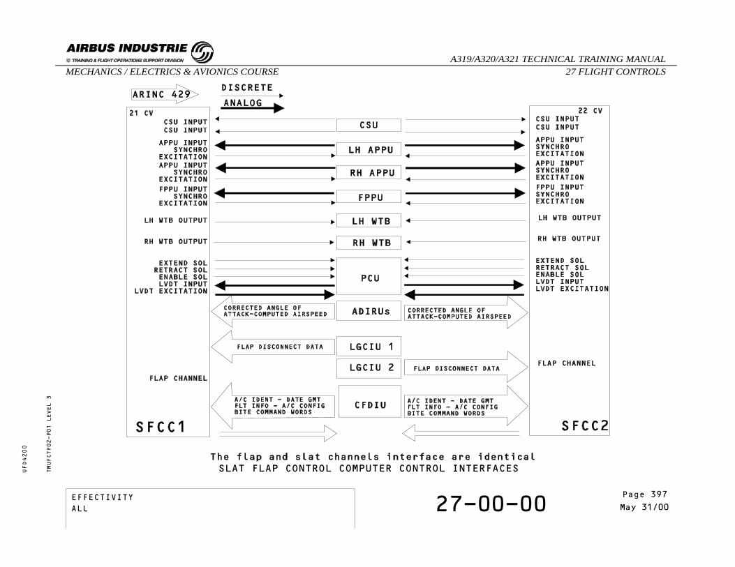
SLAT FLAP CONTROL COMPUTER CONTROL INTERFACESTMUFCTF02-P01 LEVEL 3
EFFECTIVITY 27-00-00 Page 3May 31/00
_A319/A320/A321 TECHNICAL TRAINING MANUAL27 FLIGHT CONTROLSMECHANICS / ELECTRICS & AVIONICS COURSE
UFD4200
Page 397EFFECTIVITYALL

THIS PAGE LEFT INTENTIONALLY LEFT BLANK
TMUFCTF02 LEVEL 3
EFFECTIVITY 27-00-00 Page 4May 31/00
_A319/A320/A321 TECHNICAL TRAINING MANUAL27 FLIGHT CONTROLSMECHANICS / ELECTRICS & AVIONICS COURSE
UFD4200
Page 398EFFECTIVITYALL
27 - FLIGHT CONTROLS
27-00-00 SFCC MONITOR INTERFACES
CONTENTS:Flight Warning ComputersSystem Data Acquisition ConcentratorsElevator and Aileron Computers - Spoiler ElevatorComputersFlight Augmentation ComputersGround Proximity Warning ComputerCentralized Fault Display Interface UnitAir Data/Inertial Reference UnitsCabin Intercommunication Data SystemEngine Interface Units
TMUFCTE02 LEVEL 3
EFFECTIVITY 27-00-00 Page 1Oct 31/94
_A319/A320/A321 TECHNICAL TRAINING MANUAL27 FLIGHT CONTROLSMECHANICS / ELECTRICS & AVIONICS COURSE
UFD4200
Page 399EFFECTIVITYALL
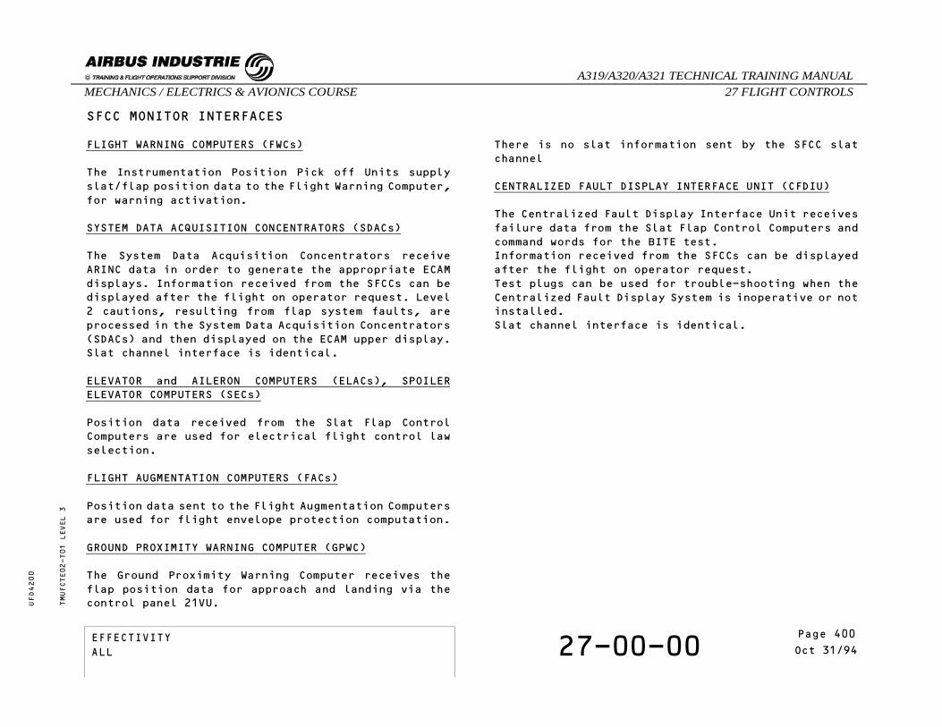
SFCC MONITOR INTERFACES
FLIGHT WARNING COMPUTERS (FWCs)
The Instrumentation Position Pick off Units supplyslat/flap position data to the Flight Warning Computer,for warning activation.
SYSTEM DATA ACQUISITION CONCENTRATORS (SDACs)
The System Data Acquisition Concentrators receiveARINC data in order to generate the appropriate ECAMdisplays. Information received from the SFCCs can bedisplayed after the flight on operator request. Level2 cautions, resulting from flap system faults, areprocessed in the System Data Acquisition Concentrators(SDACs) and then displayed on the ECAM upper display.Slat channel interface is identical.
ELEVATOR and AILERON COMPUTERS (ELACs), SPOILERELEVATOR COMPUTERS (SECs)
Position data received from the Slat Flap ControlComputers are used for electrical flight control lawselection.
FLIGHT AUGMENTATION COMPUTERS (FACs)
Position data sent to the Flight Augmentation Computersare used for flight envelope protection computation.
GROUND PROXIMITY WARNING COMPUTER (GPWC)
The Ground Proximity Warning Computer receives theflap position data for approach and landing via thecontrol panel 21VU.
There is no slat information sent by the SFCC slatchannel
CENTRALIZED FAULT DISPLAY INTERFACE UNIT (CFDIU)
The Centralized Fault Display Interface Unit receivesfailure data from the Slat Flap Control Computers andcommand words for the BITE test.Information received from the SFCCs can be displayedafter the flight on operator request.Test plugs can be used for trouble-shooting when theCentralized Fault Display System is inoperative or notinstalled.Slat channel interface is identical.
TMUFCTE02-T01 LEVEL 3
EFFECTIVITY 27-00-00 Page 2Oct 31/94
_A319/A320/A321 TECHNICAL TRAINING MANUAL27 FLIGHT CONTROLSMECHANICS / ELECTRICS & AVIONICS COURSE
UFD4200
Page 400EFFECTIVITYALL
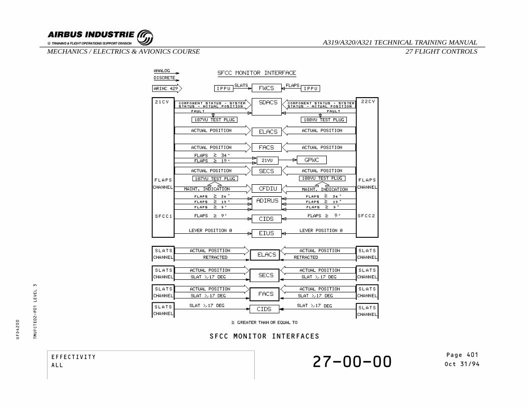
SFCC MONITOR INTERFACESTMUFCTE02-P01 LEVEL 3
EFFECTIVITY 27-00-00 Page 3Oct 31/94
_A319/A320/A321 TECHNICAL TRAINING MANUAL27 FLIGHT CONTROLSMECHANICS / ELECTRICS & AVIONICS COURSE
UFD4200
Page 401EFFECTIVITYALL

SFCC MONITOR INTERFACES
AIR DATA/INERTIAL REFERENCE UNITS (ADIRUs)
Flap position data are used by the Air Data / InertialReference Unit for Angle Of Attack and static sourcecorrection.Flaps higher than 9o and 34o data are used for AngleOf Attack correction.Flaps higher than 19o is used for the static sourcecorrection. There is no slat channel interface to theAir Data / Inertial Reference Units.
CABIN INTERCOMMUNICATION DATA SYSTEM (CIDS)
The Cabin Intercommunication Data System receives slatflap position discretes for automatic lighting of cabinpassenger signs.
ENGINE INTERFACE UNITS (EIUs)
The Engine Interface Unit receives a slat flap leverretracted position discrete for minimum idle.Slat channel interface is identical.
TMUFCTE02-T02 LEVEL 3
EFFECTIVITY 27-00-00 Page 4Oct 31/94
_A319/A320/A321 TECHNICAL TRAINING MANUAL27 FLIGHT CONTROLSMECHANICS / ELECTRICS & AVIONICS COURSE
UFD4200
Page 402EFFECTIVITYALL

SFCC MONITOR INTERFACESTMUFCTE02-P02 LEVEL 3
EFFECTIVITY 27-00-00 Page 5Oct 31/94
_A319/A320/A321 TECHNICAL TRAINING MANUAL27 FLIGHT CONTROLSMECHANICS / ELECTRICS & AVIONICS COURSE
UFD4200
Page 403EFFECTIVITYALL

THIS PAGE INTENTIONALLY LEFT BLANK
TMUFCTE02 LEVEL 3
EFFECTIVITY 27-00-00 Page 6Oct 31/94
_A319/A320/A321 TECHNICAL TRAINING MANUAL27 FLIGHT CONTROLSMECHANICS / ELECTRICS & AVIONICS COURSE
UFD4200
Page 404EFFECTIVITYALL

27 - FLIGHT CONTROLS
27-00-00 CFDS SPECIFIC PAGE PRESENTATION
CONTENTS:EFCS 1 (Specific Pages)SFCC-1 (Specific Pages)
TMUFCPG05 LEVEL 3
EFFECTIVITY 27-00-00 Page 1Aug 31/99
_A319/A320/A321 TECHNICAL TRAINING MANUAL27 FLIGHT CONTROLSMECHANICS / ELECTRICS & AVIONICS COURSE
UFD4200
Page 405EFFECTIVITYALL
CFDS SPECIFIC PAGE PRESENTATION
EFCS 1
LAST LEG REPORTThe LAST LEG REPORT displays all the system failureswhich appeared during the last flight.The failure messages contain the name of the failedLRU associated with the time at which the failureoccured and the ATA reference.
TROUBLE SHOOTING DATA The TROUBLE SHOOTING DATA displays complementary faultinformation concerning the system status before andafter the failure occurence.This function can be called from the "LAST LEG REPORT"and "PREVIOUS LEGS REPORT".
EFCS 1
PREVIOUS LEGS REPORTThe PREVIOUS LEGS REPORT presents failure messageshaving affected the system during the previous 64flight legs.The additional information presented is identical tothat presented in the LAST LEG REPORT.
EFCS 1
MEMORYThe bite memory is used for workshop maintenance only.It gives information in hexadecimal code.
TMUFCPG05-T01 LEVEL 3
EFFECTIVITY 27-00-00 Page 2Aug 31/99
_A319/A320/A321 TECHNICAL TRAINING MANUAL27 FLIGHT CONTROLSMECHANICS / ELECTRICS & AVIONICS COURSE
UFD4200
Page 406EFFECTIVITYALL

CFDS SPECIFIC PAGE PRESENTATIONTMUFCPG05-P01 LEVEL 3
EFFECTIVITY 27-00-00 Page 3Aug 31/99
_A319/A320/A321 TECHNICAL TRAINING MANUAL27 FLIGHT CONTROLSMECHANICS / ELECTRICS & AVIONICS COURSE
UFD4200
Page 407EFFECTIVITYALL

CFDS SPECIFIC PAGE PRESENTATION
EFCS 1
TEST
CAUTION : SURFACES WILL MOVE
AILERON DAMPING TESTThis test is driven by the FCDC and performed by thetwo ELACs.For each movement the FCDC memorizes a deflection speedand a pressure drop, then it deducts a damp factor.The test is not satisfactory when one of the four dampfactors is lower than the minimum value.Tested components : aileron servo control actuators
TMUFCPG05-T02 LEVEL 3
EFFECTIVITY 27-00-00 Page 4Aug 31/99
_A319/A320/A321 TECHNICAL TRAINING MANUAL27 FLIGHT CONTROLSMECHANICS / ELECTRICS & AVIONICS COURSE
UFD4200
Page 408EFFECTIVITYALL

CFDS SPECIFIC PAGE PRESENTATIONTMUFCPG05-P02 LEVEL 3
EFFECTIVITY 27-00-00 Page 5Aug 31/99
_A319/A320/A321 TECHNICAL TRAINING MANUAL27 FLIGHT CONTROLSMECHANICS / ELECTRICS & AVIONICS COURSE
UFD4200
Page 409EFFECTIVITYALL
CFDS SPECIFIC PAGE PRESENTATION
SFCC-1
Normally two SFCC menu pages are transmitted to theCFDS by the selected SFCC.But, in case of:
- PIN PROGRAMMING DISAGREEMENTIf there is a Pin Programming disagreementinstallation, the SFCC transmits a " PIN PROGDISAGREE " message.In this case, no further pages shall beprovided.
- SLAT CHANNEL NOT AVAILBLEIf slat channel is selected but not availablethe SFCC transmits a " SLAT NOT AVAILABLE "message in all options.
SLT SYSTEM STATUSThe display features the faults (class 1 or 2)affecting the system at the time of interrogation.
TMUFCPG05-T03 LEVEL 3
EFFECTIVITY 27-00-00 Page 6Aug 31/99
_A319/A320/A321 TECHNICAL TRAINING MANUAL27 FLIGHT CONTROLSMECHANICS / ELECTRICS & AVIONICS COURSE
UFD4200
Page 410EFFECTIVITYALL

CFDS SPECIFIC PAGE PRESENTATIONTMUFCPG05-P03 LEVEL 3
EFFECTIVITY 27-00-00 Page 7Aug 31/99
_A319/A320/A321 TECHNICAL TRAINING MANUAL27 FLIGHT CONTROLSMECHANICS / ELECTRICS & AVIONICS COURSE
UFD4200
Page 411EFFECTIVITYALL

CFDS SPECIFIC PAGE PRESENTATION
SFCC-1
SLAT TEST RESET
SFCC TEST FAILURE REPORT (MEMORY READ OUT)Failure data from the automatic integrity test (PWRUP TEST) or from the maintenance test (SFCC-TEST) isstored in the SFCC TEST FAILURE REPORT.If there is no failure, therefore no report, the "NOFAULTS" message is displayed.To read the failure message, the corresponding failurereport has to be selected.On selection of one PWR UP TEST report, the failuremessage is displayed.
NOTE: "L1: OUTPUT DISCRETES" denotes failure messagesabout LANE 1."L2: OUTPUT DISCRETES" denotes failure messagesabout LANE 2.
WTB-RESETWhen the START WTB RESET key is pressed, the associatedWTB solenoid valves are reset and the result isdisplayed.
TMUFCPG05-T04 LEVEL 3
EFFECTIVITY 27-00-00 Page 8Aug 31/99
_A319/A320/A321 TECHNICAL TRAINING MANUAL27 FLIGHT CONTROLSMECHANICS / ELECTRICS & AVIONICS COURSE
UFD4200
Page 412EFFECTIVITYALL

CFDS SPECIFIC PAGE PRESENTATIONTMUFCPG05-P04 LEVEL 3
EFFECTIVITY 27-00-00 Page 9Aug 31/99
_A319/A320/A321 TECHNICAL TRAINING MANUAL27 FLIGHT CONTROLSMECHANICS / ELECTRICS & AVIONICS COURSE
UFD4200
Page 413EFFECTIVITYALL

CFDS SPECIFIC PAGE PRESENTATION
SFCC-1
SLT SYSTEM DATA
PPUThe slat PPU data is refreshed every 5 seconds withupdated data.
NOTE: "272.3" represents the decimal value of thesynchro angles."C1A" represents the hexadecimal value of thesame data.
ARINC 429 INPUT STATUSWhatever the selection SLAT ARINC INPUT STATUS or FLAPARINC INPUT STATUS the display has the samepresentation. Except for FLAP an additional STATUSmessage is displayed concerning ARINC 429 inputs fromLGCIU: ("LGCIU OK").
DISCRETE INPUTSThe status of the slat discrete inputs is displayedon the MCDU.
NOTE: "$" represents function set (1) or function reset(0)."%" represents logic 1 or logic 0 as determinedby input circuit."AOG" means Aircraft On Ground."SGOI" means System Ground Operation Inhibit.
NOTE: The following data are available only in theflap channel."XX...XX" replaces FLAP RELIEF ENABLED or FLAPRELIEF DISABLED or FLAP RELIEF CODING FAIL"YY...YY" replaces MAX FLAP 25 DEG or MAX FLAPCODING FAIL
X-LINK INPUTEach channel receives and validates the followinginformation:
- LABEL 23 Attachment data- LABEL 60 Diagnosis data- LABEL 61 Unused- LABEL 62 System Status Word data- LABEL 63 FPPU Synchro Angle data- LABEL 64 LH APPU Synchro Angle data- LABEL 65 RH APPU Synchro Angle data- LABEL 67 WTB/POB data word
TMUFCPG05-T05 LEVEL 3
EFFECTIVITY 27-00-00 Page 10Aug 31/99
_A319/A320/A321 TECHNICAL TRAINING MANUAL27 FLIGHT CONTROLSMECHANICS / ELECTRICS & AVIONICS COURSE
UFD4200
Page 414EFFECTIVITYALL

CFDS SPECIFIC PAGE PRESENTATIONTMUFCPG05-P05 LEVEL 3
EFFECTIVITY 27-00-00 Page 11Aug 31/99
_A319/A320/A321 TECHNICAL TRAINING MANUAL27 FLIGHT CONTROLSMECHANICS / ELECTRICS & AVIONICS COURSE
UFD4200
Page 415EFFECTIVITYALL

CFDS SPECIFIC PAGE PRESENTATION
SFCC-1
TROUBLE SHOOTING DATAThe "TROUBLE SHOOTING DATA" item provides additionaldata about the failures (all classes) recorded duringthe last and previous legs.The failure selected on the previous page is displayedwith its snapshot data at the occurence of thisfailure.
SFCC-1
ON GROUND FAULTSThe MCDU displays the faults stored in the "on groundfailure memory"(generally limited to the 3 last faultsrecorded).But if no failures are stored, the MCDU displays the"NO FAULTS" message.
TMUFCPG05-T06 LEVEL 3
EFFECTIVITY 27-00-00 Page 12Aug 31/99
_A319/A320/A321 TECHNICAL TRAINING MANUAL27 FLIGHT CONTROLSMECHANICS / ELECTRICS & AVIONICS COURSE
UFD4200
Page 416EFFECTIVITYALL

CFDS SPECIFIC PAGE PRESENTATIONTMUFCPG05-P06 LEVEL 3
EFFECTIVITY 27-00-00 Page 13Aug 31/99
_A319/A320/A321 TECHNICAL TRAINING MANUAL27 FLIGHT CONTROLSMECHANICS / ELECTRICS & AVIONICS COURSE
UFD4200
Page 417EFFECTIVITYALL

THIS PAGE INTENTIONALLY LEFT BLANK
TMUFCPG05 LEVEL 3
EFFECTIVITY 27-00-00 Page 14Aug 31/99
_A319/A320/A321 TECHNICAL TRAINING MANUAL27 FLIGHT CONTROLSMECHANICS / ELECTRICS & AVIONICS COURSE
UFD4200
Page 418EFFECTIVITYALL