Embed Size (px)
Citation preview
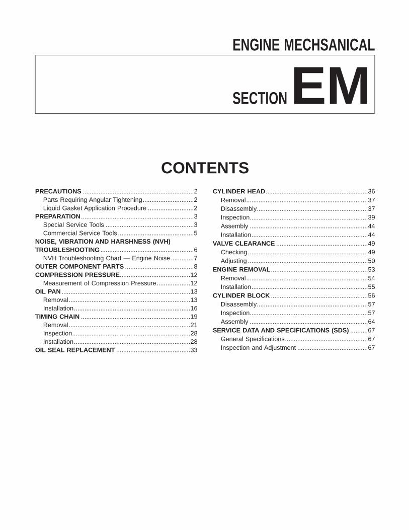
ENGINE MECHANICAL
SECTION EM
Go to Table of Contents
Go to Quick Reference Index

Parts Requiring Angular TighteningI Use an angle wrench for the final tightening of the following
engine parts:(1) Cylinder head bolts(2) Main bearing cap bolts(3) Connecting rod cap nuts(4) Crankshaft pulley bolt
I Do not use a torque value for final tightening.I The torque value for these parts are for a preliminary step.I Ensure thread and seat surfaces are clean and coated with
engine oil.
SEM164F
Liquid Gasket Application Procedurea. Use a scraper to remove all traces of old liquid gasket
from mating surfaces and grooves. Also, completely cleanany oil from these areas.
b. Apply a continuous bead of liquid gasket to mating sur-faces. (Use Genuine RTV silicone sealant Part No. 999MP-A7007, Three Bond TB1207D or equivalent.)I Be sure liquid gasket diameter is as specified.
AEM080
c. Apply liquid gasket around the inner side of bolt holes(unless otherwise specified).
d. Assembly should be done within 5 minutes after coating.e. Wait at least 30 minutes before refilling engine oil and
engine coolant.
PRECAUTIONS
EM-2

Special Service ToolsThe actual shapes of Kent-Moore tools may differ from those of special service tools illustrated here.
Tool number(Kent-Moore No.)Tool name
Description
ST0501S000( — )Engine stand assemblyq1 ST05011000
( — )Engine stand
q2 ST05012000( — )Base NT042
Disassembling and assembling
KV10106500( — )Engine stand shaft
NT028
KV10117000(J41262)Engine sub-attachment
NT373
KV10117000 has been replaced withKV10117001 (KV10117000 is no longer inproduction, but it is usable).
KV10117001( — )Engine sub-attachment
NT372
Installing on the cylinder block
ST10120000(J24239-01)Cylinder head bolt wrench
NT019
Loosening and tightening cylinder head bolt
KV10116200(J26336-A)Valve spring compressorq1 KV10115900
(J26336-20)Attachment
NT022
Disassembling valve mechanism
(J39386)Valve oil seal drift
NT024
Installing valve oil seal
PREPARATION
EM-3
Tool number(Kent-Moore No.)Tool name
Description
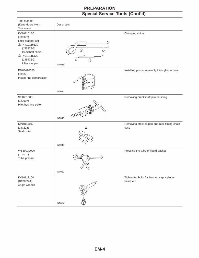
KV101151S0(J38972)Lifter stopper setq1 KV10115110
(J38972-1)Camshaft pliers
q2 KV10115120(J38972-2)Lifter stopper NT041
Changing shims
EM03470000(J8037)Piston ring compressor
NT044
Installing piston assembly into cylinder bore
ST16610001(J23907)Pilot bushing puller
NT045
Removing crankshaft pilot bushing
KV10111100(J37228)Seal cutter
NT046
Removing steel oil pan and rear timing chaincase
WS39930000( — )Tube presser
NT052
Pressing the tube of liquid gasket
KV10112100(BT8653-A)Angle wrench
NT014
Tightening bolts for bearing cap, cylinderhead, etc.
PREPARATIONSpecial Service Tools (Cont’d)
EM-4
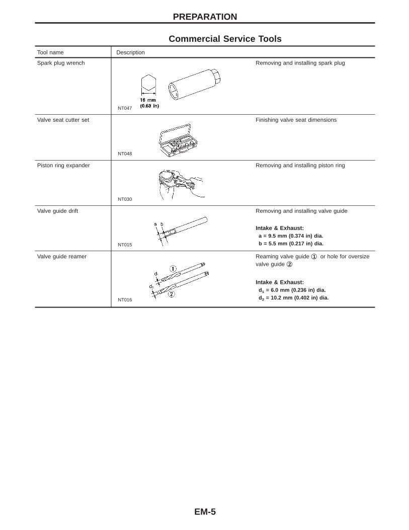
Commercial Service ToolsTool name Description
Spark plug wrench
NT047
Removing and installing spark plug
Valve seat cutter set
NT048
Finishing valve seat dimensions
Piston ring expander
NT030
Removing and installing piston ring
Valve guide drift
NT015
Removing and installing valve guide
Intake & Exhaust:a = 9.5 mm (0.374 in) dia.b = 5.5 mm (0.217 in) dia.
Valve guide reamer
NT016
Reaming valve guide q1 or hole for oversizevalve guide q2
Intake & Exhaust:d1 = 6.0 mm (0.236 in) dia.d2 = 10.2 mm (0.402 in) dia.
PREPARATION
EM-5

SEM646F
NOISE, VIBRATION AND HARSHNESS (NVH) TROUBLESHOOTING
EM-6
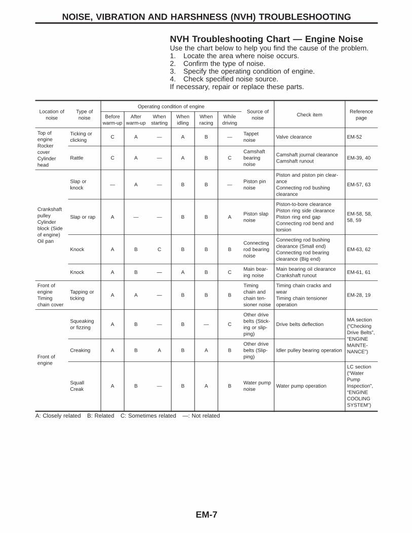
NVH Troubleshooting Chart — Engine NoiseUse the chart below to help you find the cause of the problem.1. Locate the area where noise occurs.2. Confirm the type of noise.3. Specify the operating condition of engine.4. Check specified noise source.If necessary, repair or replace these parts.
Location ofnoise
Type ofnoise
Operating condition of engineSource of
noiseCheck item
ReferencepageBefore
warm-upAfter
warm-upWhen
startingWhenidling
Whenracing
Whiledriving
Top ofengineRockercoverCylinderhead
Ticking orclicking
C A — A B —Tappetnoise
Valve clearance EM-52
Rattle C A — A B CCamshaftbearingnoise
Camshaft journal clearanceCamshaft runout
EM-39, 40
CrankshaftpulleyCylinderblock (Sideof engine)Oil pan
Slap orknock
— A — B B —Piston pinnoise
Piston and piston pin clear-anceConnecting rod bushingclearance
EM-57, 63
Slap or rap A — — B B APiston slapnoise
Piston-to-bore clearancePiston ring side clearancePiston ring end gapConnecting rod bend andtorsion
EM-58, 58,58, 59
Knock A B C B B BConnectingrod bearingnoise
Connecting rod bushingclearance (Small end)Connecting rod bearingclearance (Big end)
EM-63, 62
Knock A B — A B CMain bear-ing noise
Main bearing oil clearanceCrankshaft runout
EM-61, 61
Front ofengineTimingchain cover
Tapping orticking
A A — B B B
Timingchain andchain ten-sioner noise
Timing chain cracks andwearTiming chain tensioneroperation
EM-28, 19
Front ofengine
Squeakingor fizzing
A B — B — C
Other drivebelts (Stick-ing or slip-ping)
Drive belts deflectionMA section(“CheckingDrive Belts”,“ENGINEMAINTE-NANCE”)Creaking A B A B A B
Other drivebelts (Slip-ping)
Idler pulley bearing operation
SquallCreak
A B — B A BWater pumpnoise
Water pump operation
LC section(“WaterPumpInspection”,“ENGINECOOLINGSYSTEM”)
A: Closely related B: Related C: Sometimes related —: Not related
NOISE, VIBRATION AND HARSHNESS (NVH) TROUBLESHOOTING
EM-7
SEM648F
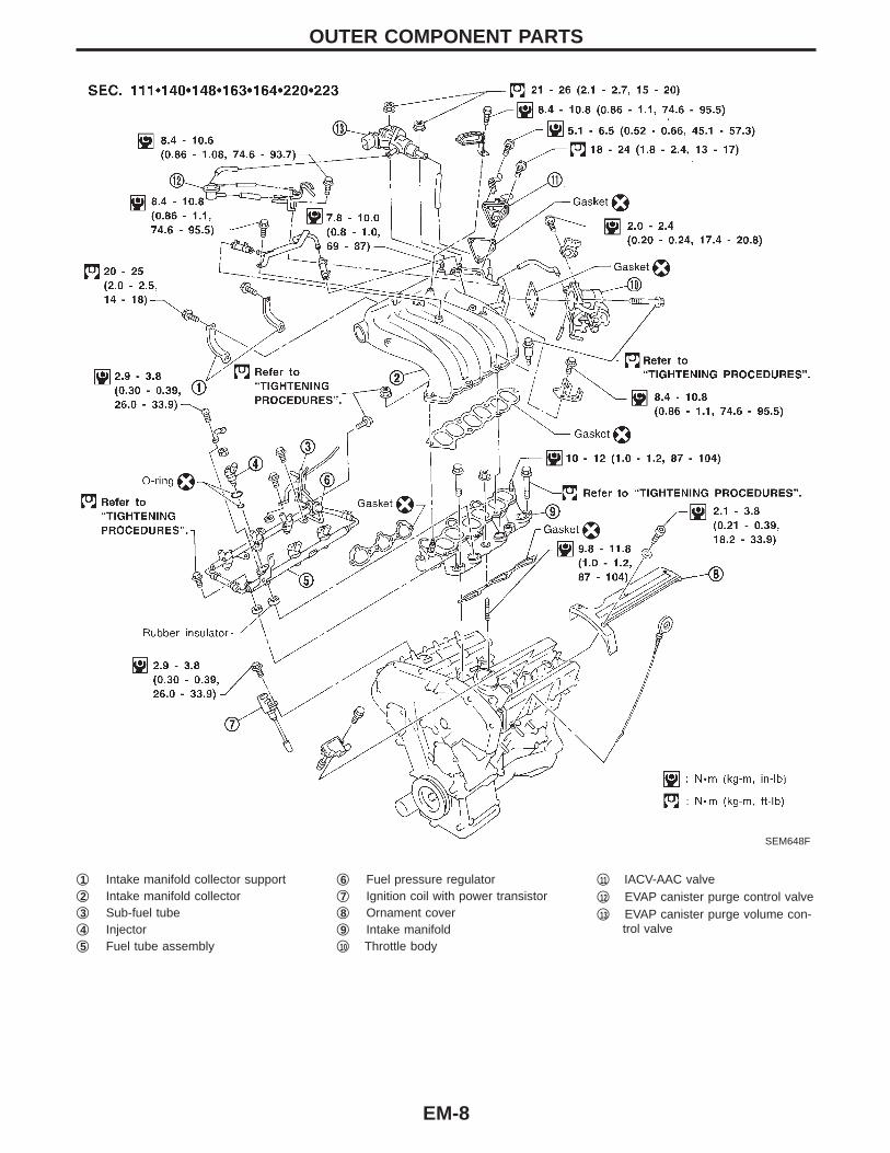
q1 Intake manifold collector supportq2 Intake manifold collectorq3 Sub-fuel tubeq4 Injectorq5 Fuel tube assembly
q6 Fuel pressure regulatorq7 Ignition coil with power transistorq8 Ornament coverq9 Intake manifoldq10 Throttle body
q11 IACV-AAC valveq12 EVAP canister purge control valveq13 EVAP canister purge volume con-
trol valve
OUTER COMPONENT PARTS
EM-8

SEM649F
q1 EGRC-BPT valveq2 EGR valveq3 EGR temperature sensor
q4 Camshaft position sensor(PHASE)
q5 Thermostat with water inlet
q6 Exhaust manifoldq7 Water outlet
OUTER COMPONENT PARTS
EM-9

SEM902EA
TIGHTENING PROCEDURES
Intake manifoldI Tighten in numerical order shown in the figure.1. Tighten all bolts and nuts to 5 to 10 N⋅m (0.5 to 1.0 kg-m, 3.6
to 7.2 ft-lb).2. Tighten all bolts and nuts to 26 to 31 N⋅m (2.7 to 3.2 kg-m, 20
to 23 ft-lb).3. Repeat step 2 at least five times to have all bolts and nuts
tightened at a torque of 26 to 31 N⋅m (2.7 to 3.2 kg-m, 20 to23 ft-lb).
SEM405F
Fuel tubeI Tighten in numerical order shown in the figure.1. Tighten all bolts to 9.3 to 10.8 N⋅m (0.95 to 1.1 kg-m, 6.9 to 8.0
ft-lb).2. Tighten all bolts to 21 to 26 N⋅m (2.1 to 2.7 kg-m, 15 to 20 ft-
lb).I Do not disassemble fuel tube assembly.
SEM150FA
Fuel pressure regulatorTighten fuel pressure regulator to 2.9 to 3.8 N⋅m (0.3 to 0.39 kg-m,26.0 to 33.9 in-lb).I Tighten screws evenly several times to have the fuel pres-
sure regulator tightened at the specified torque.I Always replace O-ring with new ones.I Lubricate O-ring with new engine oil.
SEM904EA
Sub-fuel tube1. Temporarily tighten bolt q2 .2. Tighten bolt q1 to 20.6 to 26.5 N⋅m (2.10 to 2.70 kg-m, 15.19
to 19.55 ft-lb).3. Tighten bolt q2 to 8.5 to 10.8 N⋅m (0.87 to 1.10 kg-m, 75.5 to
95.5 in-lb).
SEM905EA
Throttle bodyI Tighten in numerical order shown in the figure.1. Tighten all bolts to 8.8 to 10.8 N⋅m (0.9 to 1.1 kg-m, 6.5 to 8.0
ft-lb).2. Tighten all bolts to 17.7 to 21.6 N⋅m (1.8 to 2.2 kg-m, 13 to 16
ft-lb).
OUTER COMPONENT PARTS
EM-10

SEM897EA
EGR guide tube1. Tighten all bolts to 9 to 10 N⋅m (0.9 to 1.0 kg-m, 6.5 to 8.0 ft-
lb).2. Tighten all bolts to 21 to 26 N⋅m (2.1 to 2.7 kg-m, 15 to 20 ft-
lb).I Before installing EGR guide tube, tighten intake manifold
collector and collector bracket.
SEM151F
Intake manifold collectorTighten bolts and nuts to 18 to 22 N⋅m (1.8 to 2.2 kg-m, 13 to 16ft-lb) in numerical order shown in the figure.
OUTER COMPONENT PARTS
EM-11

SEM908E
Measurement of Compression Pressure1. Warm up engine.2. Turn ignition switch off.3. Release fuel pressure.
Refer to “Releasing Fuel Pressure” in EC section.4. Disconnect ignition coil with power transistor harness
connectors, then remove ignition coils.5. Remove all spark plugs.6. Disconnect all injector harness connectors.
SEM909E
SEM387C
7. Attach a compression tester to No. 1 cylinder.8. Depress accelerator pedal fully to keep throttle valve wide
open.9. Crank engine and record highest gauge indication.10. Repeat the measurement on each cylinder as shown above.I Always use a fully-charged battery to obtain specified
engine speed.Unit: kPa (kg/cm2, psi)/rpm
Standard MinimumDifference limit between
cylinders
1,275(13.0, 185)/300
981(10.0, 142)/300
98 (1.0, 14)/300
11. If compression in one or more cylinders is low:a. Pour a small amount of engine oil into cylinders through
spark plug holes.b. Retest compression.
I If adding oil helps compression, piston rings may be wornor damaged. If so, replace piston rings after checking pis-ton.
I If pressure stays low, a valve may be sticking or seatingimproperly. Inspect and repair valve and valve seat. (Referto SDS, EM-67 and EM-70.) If valve or valve seat is dam-aged excessively, replace them.
I If compression stays low in two cylinders that are next toeach other:a. The cylinder head gasket may be leaking, orb. Both cylinders may have valve component damage.
Inspect and repair as necessary.
COMPRESSION PRESSURE
EM-12

SEM650F
RemovalCAUTION:When removing the aluminum oil pan from engine, firstremove the crankshaft position sensors (POS and REF) fromthe assembly.Be careful not to damage sensor edges and signal plate teeth.1. Remove engine undercover.2. Drain engine oil.
SEM806E
3. Remove steel oil pan bolts.
SEM807E
4. Remove steel oil pan.a. Insert Tool between aluminum oil pan and steel oil pan.I Be careful not to damage aluminum mating surface.I Do not insert screwdriver, or oil pan flange will be
deformed.
OIL PAN
EM-13

SEM808E
b. Slide Tool by tapping on the side of the Tool with a hammer.c. Remove steel oil pan.
SEM809E
5. Remove oil strainer.
SEM810E
6. Remove front exhaust tube and its support.
SEM811E
7. Set a suitable transmission jack under transaxle and hoistengine with engine slinger.
8. Remove crankshaft position sensors (POS and REF) from oilpan.
9. Remove front and rear engine mounting nuts and bolts.10. Remove center member.
OIL PANRemoval (Cont’d)
EM-14
SEM812E
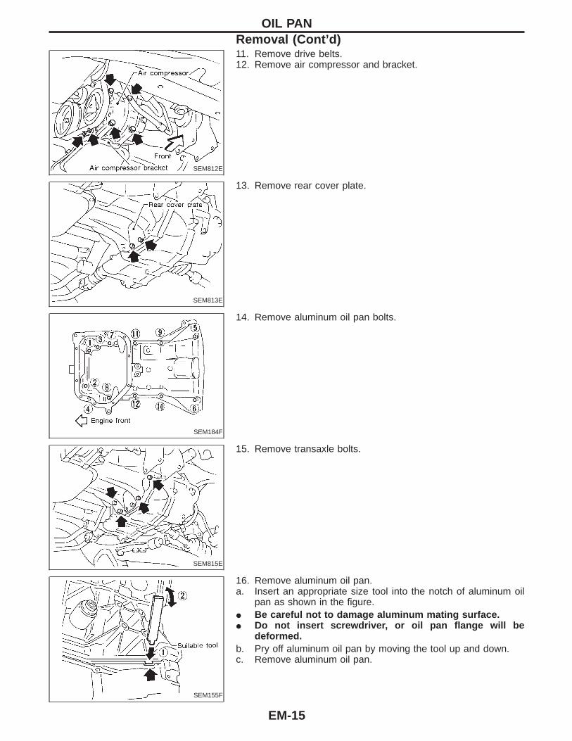
11. Remove drive belts.12. Remove air compressor and bracket.
SEM813E
13. Remove rear cover plate.
SEM184F
14. Remove aluminum oil pan bolts.
SEM815E
15. Remove transaxle bolts.
SEM155F
16. Remove aluminum oil pan.a. Insert an appropriate size tool into the notch of aluminum oil
pan as shown in the figure.I Be careful not to damage aluminum mating surface.I Do not insert screwdriver, or oil pan flange will be
deformed.b. Pry off aluminum oil pan by moving the tool up and down.c. Remove aluminum oil pan.
OIL PANRemoval (Cont’d)
EM-15

SEM819E
17. Remove O-rings from cylinder block and oil pump body.
MEM108A
Installation1. Install aluminum oil pan.a. Use a scraper to remove all traces of liquid gasket from mat-
ing surfaces.I Also remove traces of liquid gasket from mating surface of
cylinder block, front cover and steel oil pan.I Remove old liquid gasket from the bolt hole and thread.
SEM964E
b. Apply sealant to front cover gasket and rear oil seal retainergasket.
SEM159F
c. Apply a continuous bead of liquid gasket to mating surface ofaluminum oil pan.
I Use Genuine RTV silicone sealant Part No. 999MP-A7007,Three Bond TB1207D or equivalent.
SEM185FA
d. Apply liquid gasket to inner sealing surface as shown in figure.I Be sure liquid gasket is 4.0 to 5.0 mm (0.157 to 0.197 in)
or 4.5 to 5.5 mm (0.177 to 0.217 in) wide.I Attaching should be done within 5 minutes after coating.
OIL PANRemoval (Cont’d)
EM-16

SEM819E
e. Install O-rings, cylinder block and oil pump body.
SEM186F
f. Install aluminum oil pan.I Tighten bolts in numerical order.I Wait at least 30 minutes before refilling engine oil.
SEM822E
2. Install the transaxle bolts.3. Install rear cover plate.
SEM812E
4. Install air compressor and bracket.5. Install drive belts.6. Install center member.7. Install front and rear engine mounting insulator nuts and bolts.
SEM222F
8. Install crankshaft position sensors (POS and REF) and frontheated oxygen sensor (left bank) harness clamp.
I Make sure that crankshaft position sensor (POS) and frontheated oxygen sensor (left bank) harness clamp areinstalled correctly as shown in figure.
9. Install front exhaust tube and its support.10. Install oil strainer.
OIL PANInstallation (Cont’d)
EM-17

SEM823E
11. Install steel oil pan.a. Use a scraper to remove all traces of liquid gasket from mat-
ing surfaces.I Also remove traces of liquid gasket from mating surface of
aluminum oil pan.
SEM159F
b. Apply a continuous bead of liquid gasket to mating surface ofsteel oil pan.
I Use Genuine RTV silicone sealant Part No. 999MP-A7007,Three Bond TB1207D or equivalent.
I Be sure liquid gasket is 4.0 to 5.0 mm (0.157 to 0.197 in)wide.
I Attaching should be done within 5 minutes after coating.
SEM947EB
SEM806EA
c. Install steel oil pan.I Tighten in numerical order shown in the figure.I Wait at least 30 minutes before refilling engine oil.
OIL PANInstallation (Cont’d)
EM-18
SEM651F
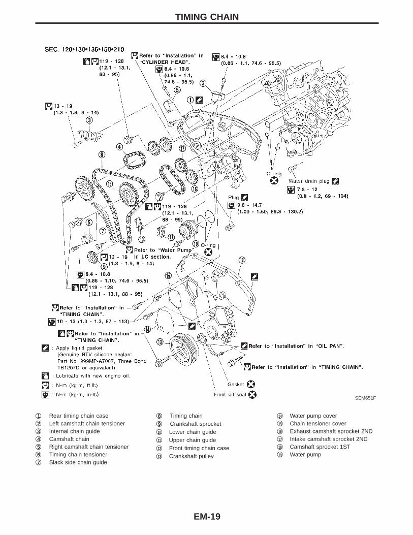
q1 Rear timing chain caseq2 Left camshaft chain tensionerq3 Internal chain guideq4 Camshaft chainq5 Right camshaft chain tensionerq6 Timing chain tensionerq7 Slack side chain guide
q8 Timing chainq9 Crankshaft sprocketq10 Lower chain guideq11 Upper chain guideq12 Front timing chain caseq13 Crankshaft pulley
q14 Water pump coverq15 Chain tensioner coverq16 Exhaust camshaft sprocket 2NDq17 Intake camshaft sprocket 2NDq18 Camshaft sprocket 1STq19 Water pump
TIMING CHAIN
EM-19

POSITION FOR APPLYING LIQUID GASKETRefer to “Installation” in “OIL PAN” for installing oil pan (EM-16).I Before installation, wipe off the protruding sealant.
SEM443FA
TIMING CHAIN
EM-20

CAUTION:I After removing timing chain, do not turn crankshaft and
camshaft separately, or valves will strike piston heads.I When installing camshafts, chain tensioners, oil seals, or
other sliding parts, lubricate contacting surfaces with newengine oil.
I Apply new engine oil to bolt threads and seat surfaceswhen installing cylinder head, camshaft sprockets, crank-shaft pulley, and camshaft brackets.
I Before disconnecting fuel hose, release fuel pressure.Refer to EC section (“Fuel Pressure Release”, “BASICSERVICE PROCEDURE”).
I When removing the oil pans, oil pump assembly and tim-ing chain from engine, first remove the camshaft positionsensor (PHASE) and the crankshaft position sensors(REF)/(POS) from the assembly.Be careful not to damage sensor edges.
I Do not spill engine coolant on drive belts.
Removal1. Drain engine oil.2. Release fuel pressure.
Refer to “Fuel Pressure Release” in EC section.3. Drain coolant by removing cylinder block drain plugs (refer to
“Water pump” in LC section) and radiator drain cock.4. Remove left side ornament cover.5. Remove air duct to intake manifold, collector, blow-by hose,
vacuum hoses, fuel hoses, wires, harness, connectors and soon.
SEM895EA
6. Remove the following.I Vacuum hosesI Water hosesI EVAP canister purge hoseI Blow-by hose
SEM896E
7. Remove RH and LH ignition coils.
TIMING CHAIN
EM-21

SEM897E
8. Remove EGR guide tube.
SEM898E
9. Remove intake manifold collector supports and intake manifoldcollector (RH cylinder head only).
SEM406F
10. Remove fuel tube assembly.I Do not disassemble fuel tube assembly.
SEM900E
11. Remove intake manifold in reverse order of installation. Referto “TIGHTENING PROCEDURES” in “OUTER COMPONENTPARTS” (EM-10).
TIMING CHAINRemoval (Cont’d)
EM-22
SEM910E
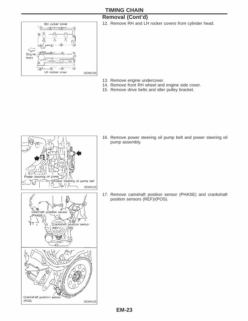
12. Remove RH and LH rocker covers from cylinder head.
13. Remove engine undercover.14. Remove front RH wheel and engine side cover.15. Remove drive belts and idler pulley bracket.
SEM911E
16. Remove power steering oil pump belt and power steering oilpump assembly.
SEM912E
17. Remove camshaft position sensor (PHASE) and crankshaftposition sensors (REF)/(POS).
TIMING CHAINRemoval (Cont’d)
EM-23
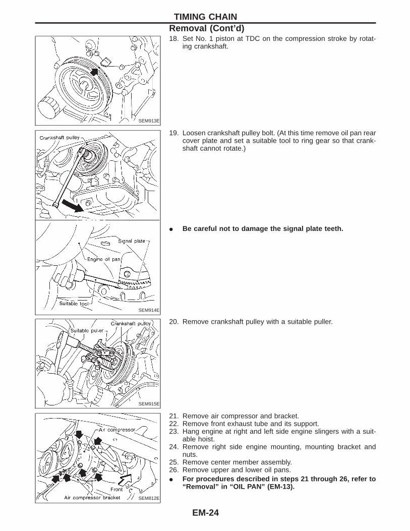
SEM913E
18. Set No. 1 piston at TDC on the compression stroke by rotat-ing crankshaft.
SEM914E
19. Loosen crankshaft pulley bolt. (At this time remove oil pan rearcover plate and set a suitable tool to ring gear so that crank-shaft cannot rotate.)
I Be careful not to damage the signal plate teeth.
SEM915E
20. Remove crankshaft pulley with a suitable puller.
SEM812E
21. Remove air compressor and bracket.22. Remove front exhaust tube and its support.23. Hang engine at right and left side engine slingers with a suit-
able hoist.24. Remove right side engine mounting, mounting bracket and
nuts.25. Remove center member assembly.26. Remove upper and lower oil pans.I For procedures described in steps 21 through 26, refer to
“Removal” in “OIL PAN” (EM-13).
TIMING CHAINRemoval (Cont’d)
EM-24

SEM916E
27. Remove water pump cover.
SEM917EA
28. Remove front timing chain case bolts.I Loosen bolts in numerical order as shown in the figure.
SEM156F
29. Remove front timing chain case.I Do not scratch sealing surfaces.
TIMING CHAINRemoval (Cont’d)
EM-25
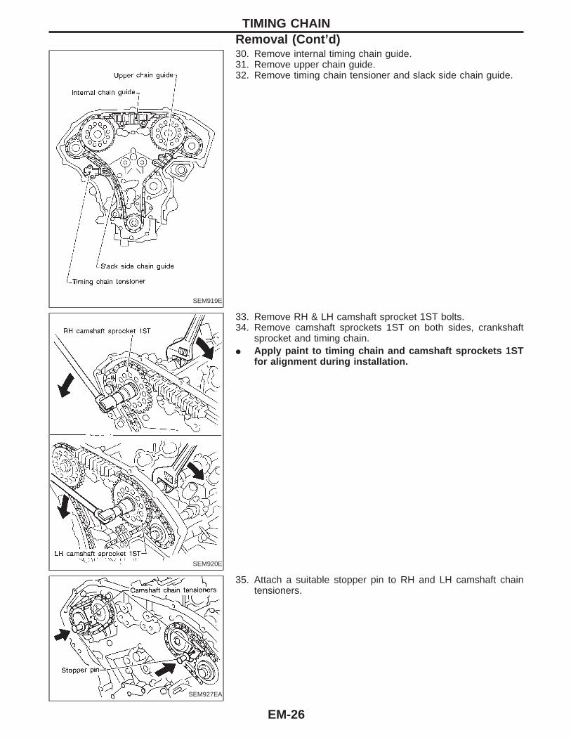
SEM919E
30. Remove internal timing chain guide.31. Remove upper chain guide.32. Remove timing chain tensioner and slack side chain guide.
SEM920E
33. Remove RH & LH camshaft sprocket 1ST bolts.34. Remove camshaft sprockets 1ST on both sides, crankshaft
sprocket and timing chain.I Apply paint to timing chain and camshaft sprockets 1ST
for alignment during installation.
SEM927EA
35. Attach a suitable stopper pin to RH and LH camshaft chaintensioners.
TIMING CHAINRemoval (Cont’d)
EM-26
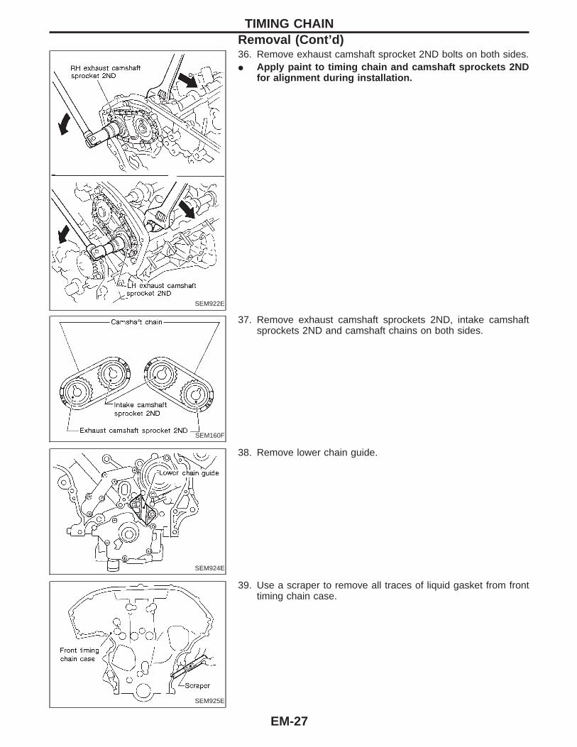
SEM922E
36. Remove exhaust camshaft sprocket 2ND bolts on both sides.I Apply paint to timing chain and camshaft sprockets 2ND
for alignment during installation.
SEM160F
37. Remove exhaust camshaft sprockets 2ND, intake camshaftsprockets 2ND and camshaft chains on both sides.
SEM924E
38. Remove lower chain guide.
SEM925E
39. Use a scraper to remove all traces of liquid gasket from fronttiming chain case.
TIMING CHAINRemoval (Cont’d)
EM-27
SEM161F
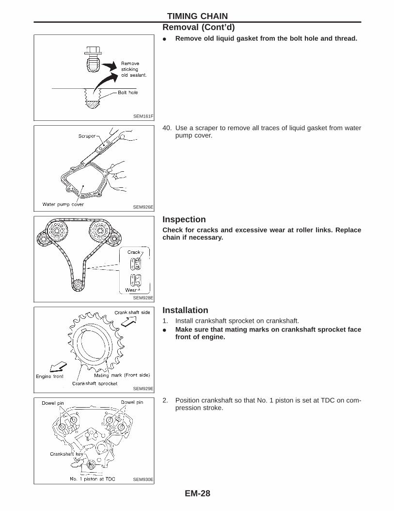
I Remove old liquid gasket from the bolt hole and thread.
SEM926E
40. Use a scraper to remove all traces of liquid gasket from waterpump cover.
SEM928E
InspectionCheck for cracks and excessive wear at roller links. Replacechain if necessary.
SEM929E
Installation1. Install crankshaft sprocket on crankshaft.I Make sure that mating marks on crankshaft sprocket face
front of engine.
SEM930E
2. Position crankshaft so that No. 1 piston is set at TDC on com-pression stroke.
TIMING CHAINRemoval (Cont’d)
EM-28
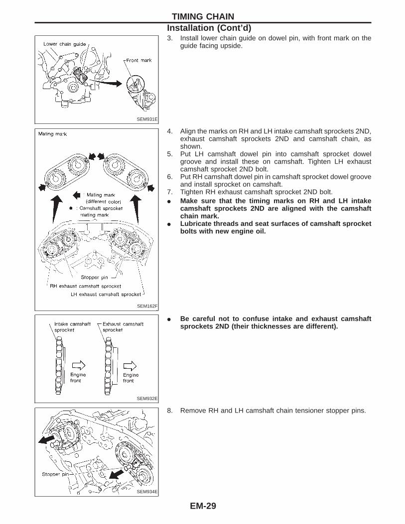
SEM931E
3. Install lower chain guide on dowel pin, with front mark on theguide facing upside.
SEM162F
4. Align the marks on RH and LH intake camshaft sprockets 2ND,exhaust camshaft sprockets 2ND and camshaft chain, asshown.
5. Put LH camshaft dowel pin into camshaft sprocket dowelgroove and install these on camshaft. Tighten LH exhaustcamshaft sprocket 2ND bolt.
6. Put RH camshaft dowel pin in camshaft sprocket dowel grooveand install sprocket on camshaft.
7. Tighten RH exhaust camshaft sprocket 2ND bolt.I Make sure that the timing marks on RH and LH intake
camshaft sprockets 2ND are aligned with the camshaftchain mark.
I Lubricate threads and seat surfaces of camshaft sprocketbolts with new engine oil.
SEM932E
I Be careful not to confuse intake and exhaust camshaftsprockets 2ND (their thicknesses are different).
SEM934E
8. Remove RH and LH camshaft chain tensioner stopper pins.
TIMING CHAINInstallation (Cont’d)
EM-29
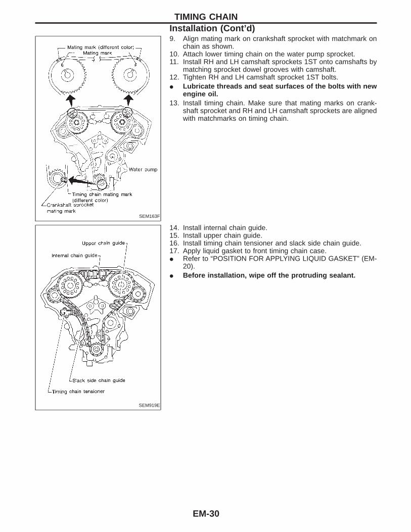
SEM163F
9. Align mating mark on crankshaft sprocket with matchmark onchain as shown.
10. Attach lower timing chain on the water pump sprocket.11. Install RH and LH camshaft sprockets 1ST onto camshafts by
matching sprocket dowel grooves with camshaft.12. Tighten RH and LH camshaft sprocket 1ST bolts.I Lubricate threads and seat surfaces of the bolts with new
engine oil.13. Install timing chain. Make sure that mating marks on crank-
shaft sprocket and RH and LH camshaft sprockets are alignedwith matchmarks on timing chain.
SEM919E
14. Install internal chain guide.15. Install upper chain guide.16. Install timing chain tensioner and slack side chain guide.17. Apply liquid gasket to front timing chain case.I Refer to “POSITION FOR APPLYING LIQUID GASKET” (EM-
20).I Before installation, wipe off the protruding sealant.
TIMING CHAINInstallation (Cont’d)
EM-30

SEM938E
18. Install rear case pin into dowel pin hole on front timing chaincase.
19. Tighten bolts to the specified torque in order shown in the fig-ure.
I Leave the bolts unattended for 30 minutes or more aftertightening.
20. Apply liquid gasket to water pump cover.I Apply a continuous bead of liquid gasket to mating surface of
water pump cover. Refer to LC section (“Water Pump Installa-tion”).
21. Install water pump cover.22. Apply liquid gasket to RH and LH rocker covers.I Use genuine liquid gasket or equivalent.I Refer to “POSITION FOR APPLYING LIQUID GASKET” (EM-
20).
SEM941EA
23. Install RH and LH rocker covers.Rocker cover tightening procedure:I Tighten in numerical order as shown in the figure.a. Tighten bolts q1 to q10 in that order to 1 to 3 N⋅m (0.1 to 0.3
kg-m, 9 to 26 in-lb).b. Tighten bolts q1 to q10 as indicated in figure to 5.4 to 7.4 N⋅m
(0.55 to 0.75 kg-m, 47.7 to 65.1 in-lb).
SEM942EB
TIMING CHAINInstallation (Cont’d)
EM-31
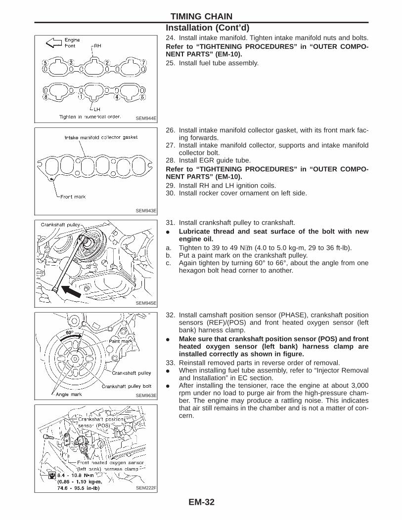
SEM944E
24. Install intake manifold. Tighten intake manifold nuts and bolts.Refer to “TIGHTENING PROCEDURES” in “OUTER COMPO-NENT PARTS” (EM-10).25. Install fuel tube assembly.
SEM943E
26. Install intake manifold collector gasket, with its front mark fac-ing forwards.
27. Install intake manifold collector, supports and intake manifoldcollector bolt.
28. Install EGR guide tube.Refer to “TIGHTENING PROCEDURES” in “OUTER COMPO-NENT PARTS” (EM-10).29. Install RH and LH ignition coils.30. Install rocker cover ornament on left side.
SEM945E
31. Install crankshaft pulley to crankshaft.I Lubricate thread and seat surface of the bolt with new
engine oil.a. Tighten to 39 to 49 N⋅m (4.0 to 5.0 kg-m, 29 to 36 ft-lb).b. Put a paint mark on the crankshaft pulley.c. Again tighten by turning 60° to 66°, about the angle from one
hexagon bolt head corner to another.
SEM963E
SEM222F
32. Install camshaft position sensor (PHASE), crankshaft positionsensors (REF)/(POS) and front heated oxygen sensor (leftbank) harness clamp.
I Make sure that crankshaft position sensor (POS) and frontheated oxygen sensor (left bank) harness clamp areinstalled correctly as shown in figure.
33. Reinstall removed parts in reverse order of removal.I When installing fuel tube assembly, refer to “Injector Removal
and Installation” in EC section.I After installing the tensioner, race the engine at about 3,000
rpm under no load to purge air from the high-pressure cham-ber. The engine may produce a rattling noise. This indicatesthat air still remains in the chamber and is not a matter of con-cern.
TIMING CHAINInstallation (Cont’d)
EM-32

SEM948E
CAUTION:When removing the oil pans, oil pump assembly and timingchain from engine, first remove the camshaft position sensor(PHASE) and the crankshaft position sensors (REF)/(POS)from the assembly.Be careful not to damage sensor edges.
VALVE OIL SEAL1. Remove LH ornament cover.2. Remove RH and LH ignition coils.3. Remove EGR guide tube.4. Remove intake manifold collector supports and intake manifold
collector (RH cylinder head only).5. Remove RH and LH rocker covers from cylinder head.6. Remove camshaft position sensor (PHASE) and crankshaft
position sensors (REF)/(POS).7. Remove oil pan. (Refer to “Removal” in “OIL PAN”, EM-13.)8. Remove timing chain. (Refer to “Removal” in “TIMING CHAIN”,
EM-21.)9. Remove camshaft brackets and camshaft. (Refer to “Disas-
sembly” in “CYLINDER HEAD”, EM-37.)10. Remove valve lifters and shims.11. Remove valve spring with Tool.12. Reinstall any parts removed in reverse order of removal.Before removing valve spring, fix valve as follows.
Method A:Piston concerned should be set at TDC to preventvalve from falling.
SEM826E
Method B:Remove spark plug, then install air hose adapterinto spark plug hole and apply air pressure to holdvalves in place. Apply a pressure of 490 kPa (5 kg/cm2, 71 psi).
SEM983D
Method C:Install spark plug with suitable washer into sparkplug hole from combustion chamber side.
OIL SEAL REPLACEMENT
EM-33

SEM827E
13. Remove valve oil seal.
SEM828E
14. Apply engine oil to new valve oil seal and install it with Tool.
SEM715A
OIL SEAL INSTALLATION DIRECTIONI Install new oil seal in the direction shown in the figure.
FRONT OIL SEAL1. Remove the following parts:I Engine undercoverI Front RH wheel and engine side coverI Drive beltsI Crankshaft position sensor (REF)I Crankshaft pulleyBe careful not to damage sensor edge.
SEM829E
2. Remove front oil seal using a suitable tool.Be careful not to scratch front cover.3. Apply engine oil to new oil seal and install it using a suitable
tool.
OIL SEAL REPLACEMENT
EM-34
SEM830E
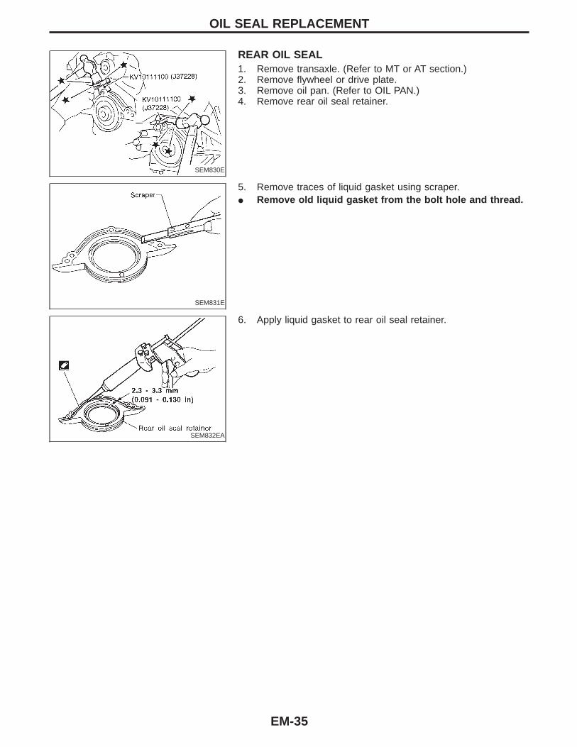
REAR OIL SEAL1. Remove transaxle. (Refer to MT or AT section.)2. Remove flywheel or drive plate.3. Remove oil pan. (Refer to OIL PAN.)4. Remove rear oil seal retainer.
SEM831E
5. Remove traces of liquid gasket using scraper.I Remove old liquid gasket from the bolt hole and thread.
SEM832EA
6. Apply liquid gasket to rear oil seal retainer.
OIL SEAL REPLACEMENT
EM-35

SEM187FB
q1 Oil filler capq2 Rocker coverq3 Camshaft bracketq4 Camshaftq5 PCV valve
q6 Cylinder headq7 Blow-by hoseq8 Spark plugq9 Valveq10 Valve spring seat
q11 Valve springq12 Valve spring retainerq13 Valve colletq14 Valve lifterq15 Shim
CYLINDER HEAD
EM-36

CAUTION:I When installing camshafts, chain tensioners, oil seals, or
other sliding parts, lubricate contacting surfaces with newengine oil.
I Apply new engine oil to threads and seat surfaces wheninstalling cylinder head, camshaft sprocket, crankshaftpulley, and camshaft bracket.
I Attach tags to valve lifters so as not to mix them up.
RemovalI This removal is the same procedure as that for timing
chain. Refer to “Removal” in “TIMING CHAIN” (EM-21).I Apply paint to camshaft sprockets for alignment during
installation.
SEM167F
Disassembly1. Remove rear timing chain case bolts.
SEM168FA
2. Remove rear timing chain case.
SEM856E
3. Remove intake and exhaust camshafts and camshaft brackets.I Equally loosen camshaft bracket bolts in several steps in the
numerical order shown in the figure.For reinstallation, be sure to put marks on camshaft bracketbefore removal.4. Remove valve component parts.
Refer to “VALVE OIL SEAL” in “OIL SEAL REPLACEMENT”(EM-33).
CYLINDER HEAD
EM-37
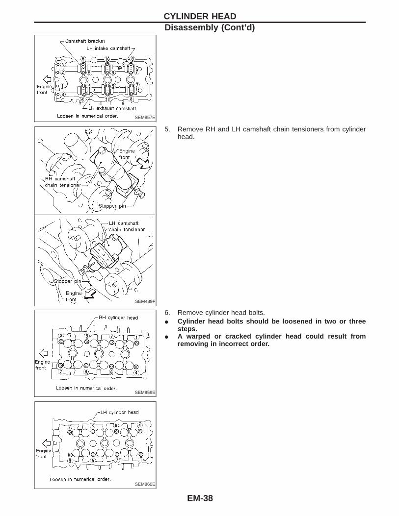
SEM857E
SEM489F
5. Remove RH and LH camshaft chain tensioners from cylinderhead.
SEM859E
6. Remove cylinder head bolts.I Cylinder head bolts should be loosened in two or three
steps.I A warped or cracked cylinder head could result from
removing in incorrect order.
SEM860E
CYLINDER HEADDisassembly (Cont’d)
EM-38

SEM863E
7. Remove cylinder head.
SEM861E
InspectionCYLINDER HEAD DISTORTIONClean surface of cylinder head.Use a reliable straightedge and feeler gauge to check the flatnessof cylinder head surface.Check along six positions shown in the figure.
Head surface flatness: Limit 0.1 mm (0.004 in)If beyond the specified limit, resurface or replace it.The limit for cylinder head resurfacing is determined by thecylinder block resurfacing.
Resurfacing limit:Amount of cylinder head resurfacing is “A”.Amount of cylinder block resurfacing is “B”.
The maximum limit : A + B = 0.2 mm (0.008 in)After resurfacing cylinder head, check that camshaft rotates freelyby hand. If resistance is felt, cylinder head must be replaced.
Nominal cylinder head height:126.3 - 126.5 mm (4.972 - 4.980 in)
SEM191F
CAMSHAFT VISUAL CHECKCheck camshaft for scratches, seizure and wear.
CAMSHAFT RUNOUT1. Measure camshaft runout at A and B as shown in the figure.
Runout (Total indicator reading):Limit 0.05 mm (0.0020 in)
2. If it exceeds the limit, replace camshaft.
SEM549A
CAMSHAFT CAM HEIGHT1. Measure camshaft cam height.
Standard cam height:43.940 - 44.130 mm (1.7299 - 1.7374 in)
Cam wear limit:0.2 mm (0.008 in)
2. If wear is beyond the limit, replace camshaft.
CYLINDER HEADDisassembly (Cont’d)
EM-39
SEM862E
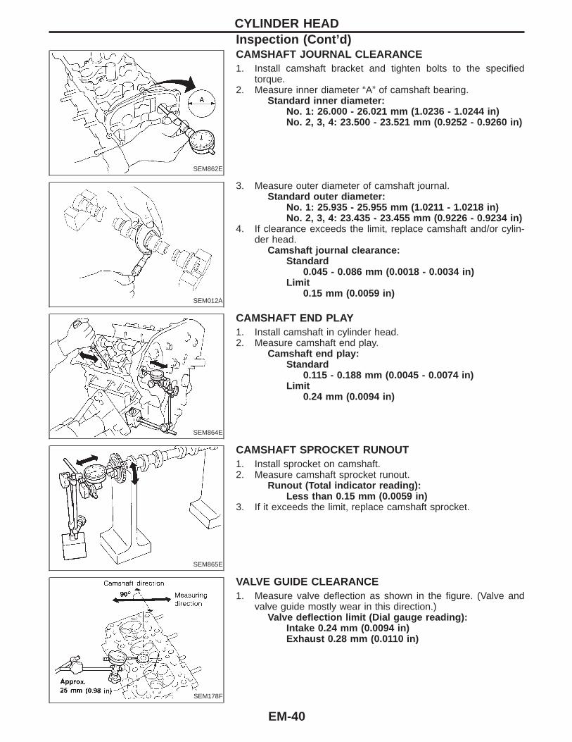
CAMSHAFT JOURNAL CLEARANCE1. Install camshaft bracket and tighten bolts to the specified
torque.2. Measure inner diameter “A” of camshaft bearing.
Standard inner diameter:No. 1: 26.000 - 26.021 mm (1.0236 - 1.0244 in)No. 2, 3, 4: 23.500 - 23.521 mm (0.9252 - 0.9260 in)
SEM012A
3. Measure outer diameter of camshaft journal.Standard outer diameter:
No. 1: 25.935 - 25.955 mm (1.0211 - 1.0218 in)No. 2, 3, 4: 23.435 - 23.455 mm (0.9226 - 0.9234 in)
4. If clearance exceeds the limit, replace camshaft and/or cylin-der head.
Camshaft journal clearance:Standard
0.045 - 0.086 mm (0.0018 - 0.0034 in)Limit
0.15 mm (0.0059 in)
SEM864E
CAMSHAFT END PLAY1. Install camshaft in cylinder head.2. Measure camshaft end play.
Camshaft end play:Standard
0.115 - 0.188 mm (0.0045 - 0.0074 in)Limit
0.24 mm (0.0094 in)
SEM865E
CAMSHAFT SPROCKET RUNOUT1. Install sprocket on camshaft.2. Measure camshaft sprocket runout.
Runout (Total indicator reading):Less than 0.15 mm (0.0059 in)
3. If it exceeds the limit, replace camshaft sprocket.
SEM178F
VALVE GUIDE CLEARANCE1. Measure valve deflection as shown in the figure. (Valve and
valve guide mostly wear in this direction.)Valve deflection limit (Dial gauge reading):
Intake 0.24 mm (0.0094 in)Exhaust 0.28 mm (0.0110 in)
CYLINDER HEADInspection (Cont’d)
EM-40

SEM938C
2. If it exceeds the limit, check valve to valve guide clearance.a. Measure valve stem diameter and valve guide inner diameter.b. Check that clearance is within specification.
Valve to valve guide clearance limit:Intake 0.08 mm (0.0031 in)Exhaust 0.1 mm (0.004 in)
c. If it exceeds the limit, replace valve or valve guide.
SEM008A
VALVE GUIDE REPLACEMENT1. To remove valve guide, heat cylinder head to 110 to 130°C
(230 to 266°F) by soaking in heated oil.
SEM931C
2. Drive out valve guide with a press [under a 20 kN (2 ton, 2.2US ton, 2.0 Imp ton) pressure] or hammer and suitable tool.
SEM932C
3. Ream cylinder head valve guide hole.Valve guide hole diameter(for service parts):
10.185 - 10.196 mm (0.4010 - 0.4014 in)
SEM950E
4. Heat cylinder head to 110 to 130°C (230 to 266°F) and pressservice valve guide onto cylinder head.
Projection “L”:12.6 - 12.8 mm (0.496 - 0.504 in)
5. Ream valve guide.Finished size:
6.000 - 6.018 mm (0.2362 - 0.2369 in)
CYLINDER HEADInspection (Cont’d)
EM-41

SEM934C
VALVE SEATSCheck valve seats for any evidence of pitting at valve contactsurface, and reseat or replace if it has worn out excessively.I Before repairing valve seats, check valve and valve guide
for wear. If they have worn, replace them. Then correctvalve seat.
I Use both hands to cut uniformly.
SEM795A
REPLACING VALVE SEAT FOR SERVICE PARTS1. Bore out old seat until it collapses. Boring should not continue
beyond the bottom face of the seat recess in cylinder head. Setthe machine depth stop to ensure this.
2. Ream cylinder head recess for service valve seat.Oversize [0.5 mm (0.020 in)]:
Intake 37.500 - 37.516 mm (1.4764 - 1.4770 in)Exhaust 32.700 - 32.716 mm (1.2874 - 1.2880 in)
Be sure to ream in circles concentric to the valve guide cen-ter.This will enable valve seat to fit correctly.
SEM892B
3. Heat cylinder head to 110 to 130°C (230 to 266°F) by soakingin heated oil.
4. Press fit valve seat until it seats on the bottom.5. Cut or grind valve seat using suitable tool to the specified
dimensions as shown in SDS (EM-70).6. After cutting, lap valve seat with abrasive compound.7. Check valve seating condition.
Seat face angle “ α”: 44°53 ′ - 45°07′ deg.Contacting width “W”:
Intake 1.09 - 1.31 mm (0.0429 - 0.0516 in)Exhaust 1.29 - 1.51 mm (0.0508 - 0.0594 in)
SEM621F
8. Use a depth gauge to measure the distance between themounting surface of the cylinder head spring seat and thevalve stem end. If the distance is shorter than specified, repeatstep 5 above to adjust it. If it is longer, replace the valve seatwith a new one.
Valve seat resurface limit “L”:Intake 41.07 - 41.67 mm (1.6169 - 1.6405 in)Exhaust 40.06 - 41.60 mm (1.5772 - 1.6378 in)
SEM188A
VALVE DIMENSIONSCheck dimensions of each valve. For dimensions, refer to SDS(EM-67).When valve head has been worn down to 0.5 mm (0.020 in) inmargin thickness, replace valve.Grinding allowance for valve stem tip is 0.2 mm (0.008 in) orless.
CYLINDER HEADInspection (Cont’d)
EM-42

SEM288A
VALVE SPRING
Squareness1. Measure dimension “S”.
Out-of-square “S”:Less than 2.0 mm (0.079 in)
2. If it exceeds the limit, replace spring.
EM113
PressureCheck valve spring pressure at specified spring height.
Pressure:Standard
454 N (46.3 kg, 102.1 lb)at height 27.55 mm (1.0846 in)
LimitMore than 427 N (43.6 kg, 96.0 lb)at height 27.55 mm (1.0846 in)
If it exceeds the limit, replace spring.
SEM960E
VALVE LIFTER1. Check contact and sliding surfaces for wear or scratches.
SEM961E
2. Check diameter of valve lifter and valve lifter guide bore.Valve lifter outer diameter:
34.960 - 34.975 mm (1.3764 - 1.3770 in)
SEM867E
Lifter guide bore diameter:35.000 - 35.021 mm (1.3780 - 1.3788 in)
CYLINDER HEADInspection (Cont’d)
EM-43

SEM085D
Assembly1. Install valve component parts.I Always use new valve oil seal. Refer to OIL SEAL
REPLACEMENT (EM-33).I Before installing valve oil seal, install valve spring seat.I Install valve spring (uneven pitch type) with its narrow
pitch side toward cylinder head side (paint mark).I After installing valve component parts, tap valve stem tip with
plastic hammer to assure a proper fit.
SEM891E
Installation1. Before installing rear timing chain case, remove all traces of
liquid gasket from mating surface using a scraper.I Also remove traces of liquid gasket from mating surface of
cylinder block.
SEM161F
I Remove old liquid gasket from the bolt hole and thread.
SEM892E
2. Before installing cam bracket, remove all traces of liquid gas-ket from mating surface using a scraper.
3. Remove O-rings from cylinder block.
SEM875E
4. Turn crankshaft until No. 1 piston is set at approximately 240°before TDC on compression stroke to prevent interference ofvalves and pistons.
CYLINDER HEAD
EM-44
SEM876E
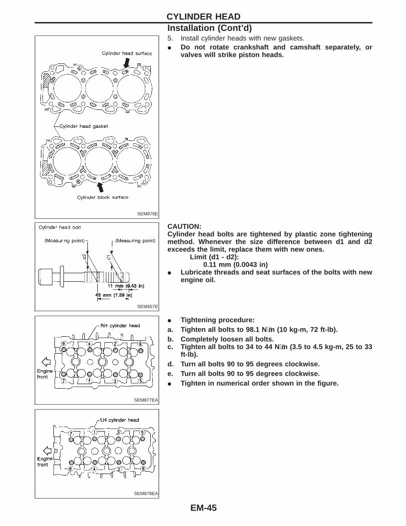
5. Install cylinder heads with new gaskets.I Do not rotate crankshaft and camshaft separately, or
valves will strike piston heads.
SEM957E
CAUTION:Cylinder head bolts are tightened by plastic zone tighteningmethod. Whenever the size difference between d1 and d2exceeds the limit, replace them with new ones.
Limit (d1 - d2):0.11 mm (0.0043 in)
I Lubricate threads and seat surfaces of the bolts with newengine oil.
SEM877EA
I Tightening procedure:a. Tighten all bolts to 98.1 N ⋅m (10 kg-m, 72 ft-lb).b. Completely loosen all bolts.c. Tighten all bolts to 34 to 44 N ⋅m (3.5 to 4.5 kg-m, 25 to 33
ft-lb).d. Turn all bolts 90 to 95 degrees clockwise.e. Turn all bolts 90 to 95 degrees clockwise.I Tighten in numerical order shown in the figure.
SEM878EA
CYLINDER HEADInstallation (Cont’d)
EM-45
SEM879EA
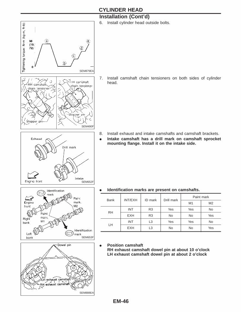
6. Install cylinder head outside bolts.
SEM490F
7. Install camshaft chain tensioners on both sides of cylinderhead.
SEM652F
8. Install exhaust and intake camshafts and camshaft brackets.I Intake camshaft has a drill mark on camshaft sprocket
mounting flange. Install it on the intake side.
SEM653F
I Identification marks are present on camshafts.
Bank INT/EXH ID mark Drill markPaint mark
M1 M2
RHINT R3 Yes Yes No
EXH R3 No No Yes
LHINT L3 Yes Yes No
EXH L3 No No Yes
SEM888EA
I Position camshaftRH exhaust camshaft dowel pin at about 10 o’clockLH exhaust camshaft dowel pin at about 2 o’clock
CYLINDER HEADInstallation (Cont’d)
EM-46

SEM884EB
9. Before installing camshaft brackets, apply sealant to matingsurface of No. 1 journal head.
I Use Genuine RTV silicone sealant Part No. 999MP-A7007,Three Bond TB1207D or equivalent.
I Refer to “POSITION FOR APPLYING LIQUID GASKET”(EM-20).
I Install camshaft brackets in their original positions.I Tighten camshaft bracket bolts gradually in two or three
stages.I If any part of valve assembly or camshaft is replaced,
check valve clearance according to reference data.After completing assembly check valve clearance. Referto “Checking” and “Adjusting” in “VALVE CLEARANCE”(EM-49 and 50).
Reference data valve clearance (Cold):Intake
0.26 - 0.34 mm (0.010 - 0.013 in)Exhaust
0.29 - 0.37 mm (0.011 - 0.015 in)I Lubricate threads and seat surfaces of camshaft bracket
bolts with new engine oil before installing them.
SEM188F
I Align stamp mark as shown in the figure.
SEM885EA
Tightening procedureTighten the camshaft brackets in the following steps.
Step Tightening torque Tightening order
1 1.96 N⋅m (0.2 kg-m, 17 in-lb)Tighten in the order of q7 to q10 ,
then tighten q1 to q6 .
2 6 N⋅m (0.6 kg-m, 52 in-lb) Tighten in the numerical order.
39.02 - 11.8 N⋅m (0.92 - 1.20 kg-m,
79.9 - 104.2 in-lb)Tighten in the numerical order.
I Tighten in numerical order shown in the figure.
SEM886EA
CYLINDER HEADInstallation (Cont’d)
EM-47
SEM887E
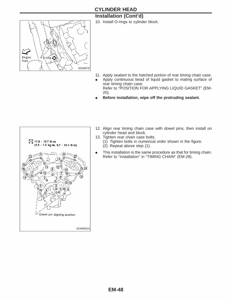
10. Install O-rings to cylinder block.
11. Apply sealant to the hatched portion of rear timing chain case.I Apply continuous bead of liquid gasket to mating surface of
rear timing chain case.Refer to “POSITION FOR APPLYING LIQUID GASKET” (EM-20).
I Before installation, wipe off the protruding sealant.
SEM890EA
12. Align rear timing chain case with dowel pins, then install oncylinder head and block.
13. Tighten rear chain case bolts.(1) Tighten bolts in numerical order shown in the figure.(2) Repeat above step (1).
I This installation is the same procedure as that for timing chain.Refer to “Installation” in “TIMING CHAIN” (EM-28).
CYLINDER HEADInstallation (Cont’d)
EM-48

SEM868E
CheckingCheck valve clearance while engine is cold and not running.1. Remove intake manifold collector.2. Remove rocker ornament covers.3. Remove RH and LH rocker covers.4. Remove all spark plugs.5. Set No. 1 cylinder at TDC on its compression stroke.I Align pointer with TDC mark on crankshaft pulley.I Check that valve lifters on No. 1 cylinder are loose and valve
lifters on No. 4 are tight.
If not, turn crankshaft one revolution (360°) and align as above.
SEM893E
6. Check only those valves shown in the figure.
ValveCrankposition
No. 1 No. 2 No. 3 No. 4 No. 5 No. 6
INT EXH INT EXH INT EXH INT EXH INT EXH INT EXH
No. 1 TDC q q q q
SEM139D
I Using a feeler gauge, measure clearance between valve lifterand camshaft.
I Record any valve clearance measurements which are out ofspecification. They will be used later to determine the requiredreplacement adjusting shim.
Valve clearance for checking (Cold):Intake
0.26 - 0.34 mm (0.010 - 0.013 in)Exhaust
0.29 - 0.37 mm (0.011 - 0.015 in)
VALVE CLEARANCE
EM-49

SEM894E
7. Turn crankshaft 240° and align as above.8. Set No. 3 cylinder at TDC on its compression stroke.9. Check only those valves shown in the figure.
ValveCrankposition
No. 1 No. 2 No. 3 No. 4 No. 5 No. 6
INT EXH INT EXH INT EXH INT EXH INT EXH INT EXH
No. 3 TDC q q q q
SEM958E
10. Turn crankshaft 240° and align as above.11. Set No. 5 cylinder at TDC on its compression stroke.12. Check only those valves shown in the figure.
ValveCrankposition
No. 1 No. 2 No. 3 No. 4 No. 5 No. 6
INT EXH INT EXH INT EXH INT EXH INT EXH INT EXH
No. 5 TDC q q q q
13. If all valve clearances are within specification, install the fol-lowing parts.
I Intake manifold collectorI RH and LH rocker coversI All spark plugsI Rocker cover ornament
SEM557EB
AdjustingAdjust valve clearance while engine is cold.1. Turn crankshaft, to position cam lobe on camshaft of valve that
must be adjusted upward.2. Place Tool (A) around camshaft as shown in figure.Before placing Tool (A), rotate notch toward center of cylinderhead (See figure.), to simplify shim removal later.CAUTION:Be careful not to damage cam surface with Tool (A).
VALVE CLEARANCEChecking (Cont’d)
EM-50

SEM869E
3. Rotate Tool (A) (See figure.) so that valve lifter is pushed down.
SEM870E
4. Place Tool (B) between camshaft and the edge of the valvelifter to retain valve lifter.
CAUTION:I Tool (B) must be placed as close to camshaft bracket as
possible.I Be careful not to damage cam surface with Tool (B).5. Remove Tool (A).
SEM871E
6. Blow air into the hole to separate adjusting shim from valvelifter.
SEM872E
SEM145D
7. Remove adjusting shim using a small screwdriver and a mag-netic finger.
8. Determine replacement adjusting shim size following formula.I Using a micrometer determine thickness of removed shim.I Calculate thickness of new adjusting shim so valve clearance
comes within specified values.R = Thickness of removed shimN = Thickness of new shimM = Measured valve clearance
Intake:N = R + [M − 0.30 mm (0.0118 in)]
Exhaust:N = R + [M − 0.33 mm (0.0130 in)]
Shims are available in 64 sizes from 2.32 mm (0.0913 in) to 2.95mm (0.1161 in), in steps of 0.01 mm (0.0004 in).I Select new shim with thickness as close as possible to calcu-
lated value.
VALVE CLEARANCEAdjusting (Cont’d)
EM-51

SEM873E
SEM146D
9. Install new shim using a suitable tool.I Install with the surface on which the thickness is stamped
facing down.
SEM874E
10. Place Tool (A) as mentioned in steps 2 and 3.11. Remove Tool (B).12. Remove Tool (A).13. Recheck valve clearance.Valve clearance:
Unit: mm (in)
Cold Hot* (reference data)
Intake 0.26 - 0.34 (0.010 - 0.013) 0.304 - 0.416 (0.012 - 0.016)
Exhaust 0.29 - 0.37 (0.011 - 0.015) 0.308 - 0.432 (0.012 - 0.017)
*: Approximately 80°C (176°F)
VALVE CLEARANCEAdjusting (Cont’d)
EM-52
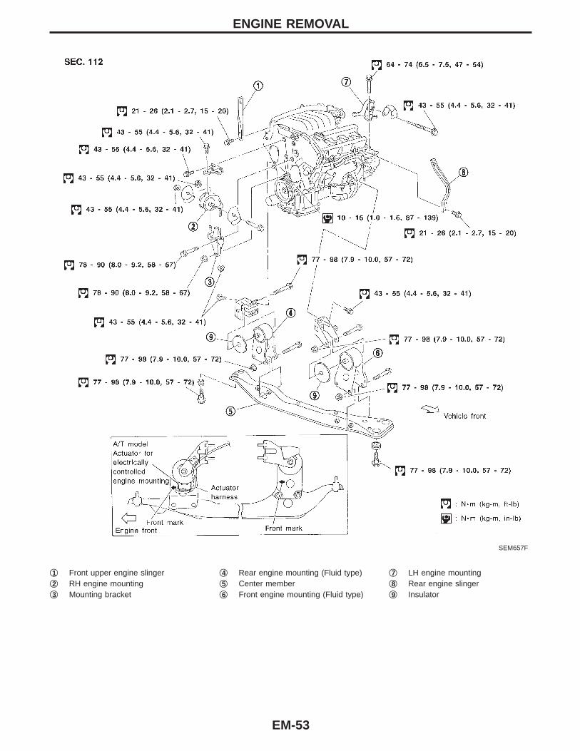
SEM657F
q1 Front upper engine slingerq2 RH engine mountingq3 Mounting bracket
q4 Rear engine mounting (Fluid type)q5 Center memberq6 Front engine mounting (Fluid type)
q7 LH engine mountingq8 Rear engine slingerq9 Insulator
ENGINE REMOVAL
EM-53
WARNING:I Situate vehicle on a flat and solid surface.I Place chocks at front and back of rear wheels.I Do not remove engine until exhaust system has com-
pletely cooled off.Otherwise, you may burn yourself and/or fire may breakout in fuel line.
I For safety during subsequent steps, the tension of wiresshould be slackened against the engine.
I Before disconnecting fuel hose, release fuel pressurefrom fuel line.Refer to “Fuel Pressure Release”, “BASIC SERVICE PRO-CEDURE” in EC section.
I Before removing front axle from transaxle, place safetystands under designated front supporting points. Refer toGI section for lifting points and towing.
I Be sure to hoist engine and transaxle in a safe manner.I For engines not equipped with engine slingers, attach
proper slingers and bolts described in PARTS CATALOG.CAUTION:I When lifting engine, be careful not to strike adjacent parts,
especially the following: Accelerator wire casing, brakelines, and brake master cylinder.
I In hoisting the engine, always use engine slingers in asafe manner.
I In removing drive shaft, be careful not to damage greaseseal of transaxle.
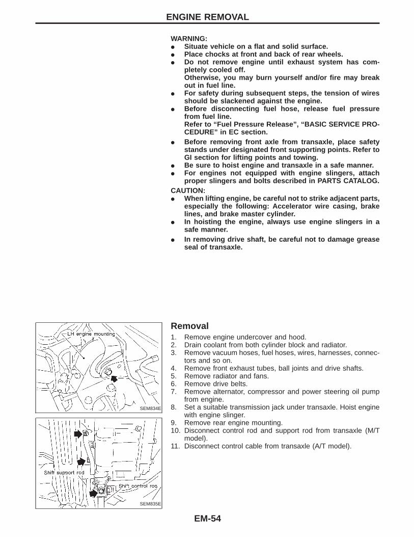
SEM834E
SEM835E
Removal1. Remove engine undercover and hood.2. Drain coolant from both cylinder block and radiator.3. Remove vacuum hoses, fuel hoses, wires, harnesses, connec-
tors and so on.4. Remove front exhaust tubes, ball joints and drive shafts.5. Remove radiator and fans.6. Remove drive belts.7. Remove alternator, compressor and power steering oil pump
from engine.8. Set a suitable transmission jack under transaxle. Hoist engine
with engine slinger.9. Remove rear engine mounting.10. Disconnect control rod and support rod from transaxle (M/T
model).11. Disconnect control cable from transaxle (A/T model).
ENGINE REMOVAL
EM-54
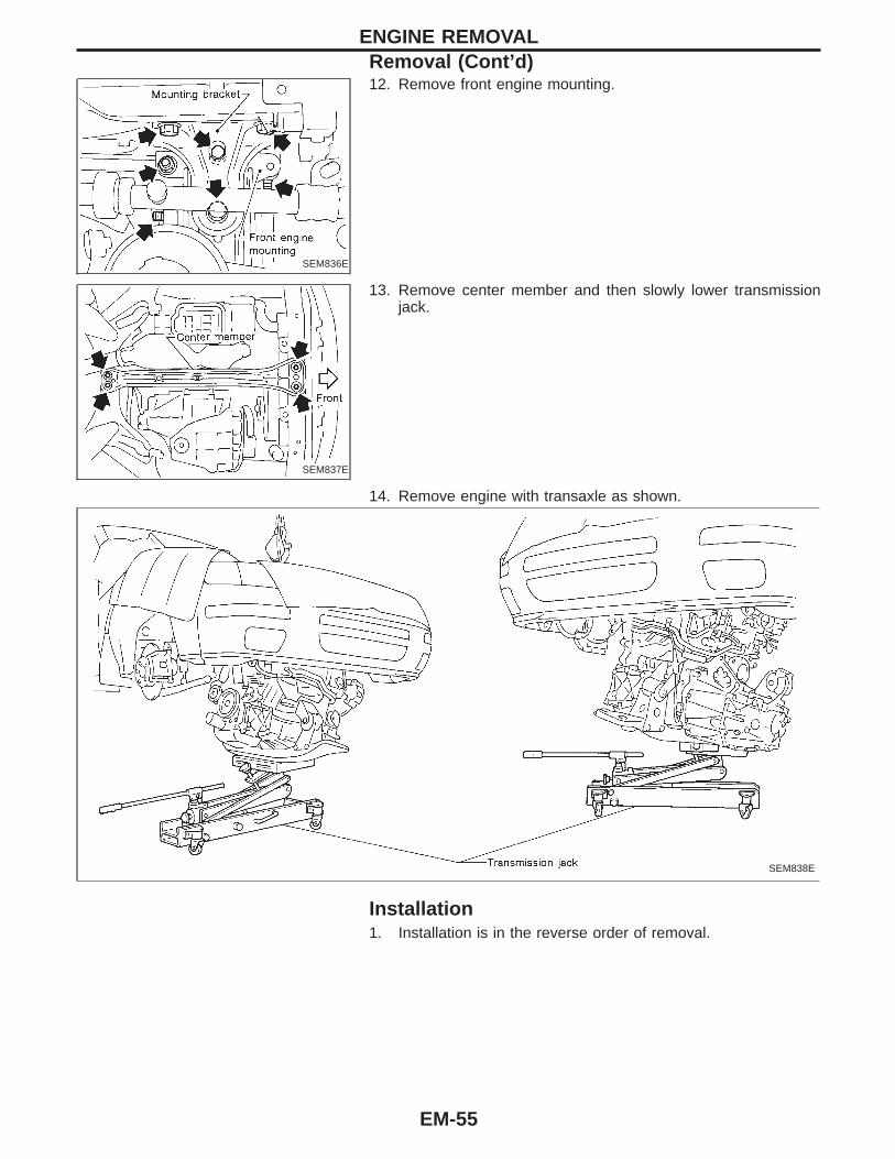
SEM836E
12. Remove front engine mounting.
SEM837E
13. Remove center member and then slowly lower transmissionjack.
14. Remove engine with transaxle as shown.
SEM838E
Installation1. Installation is in the reverse order of removal.
ENGINE REMOVALRemoval (Cont’d)
EM-55
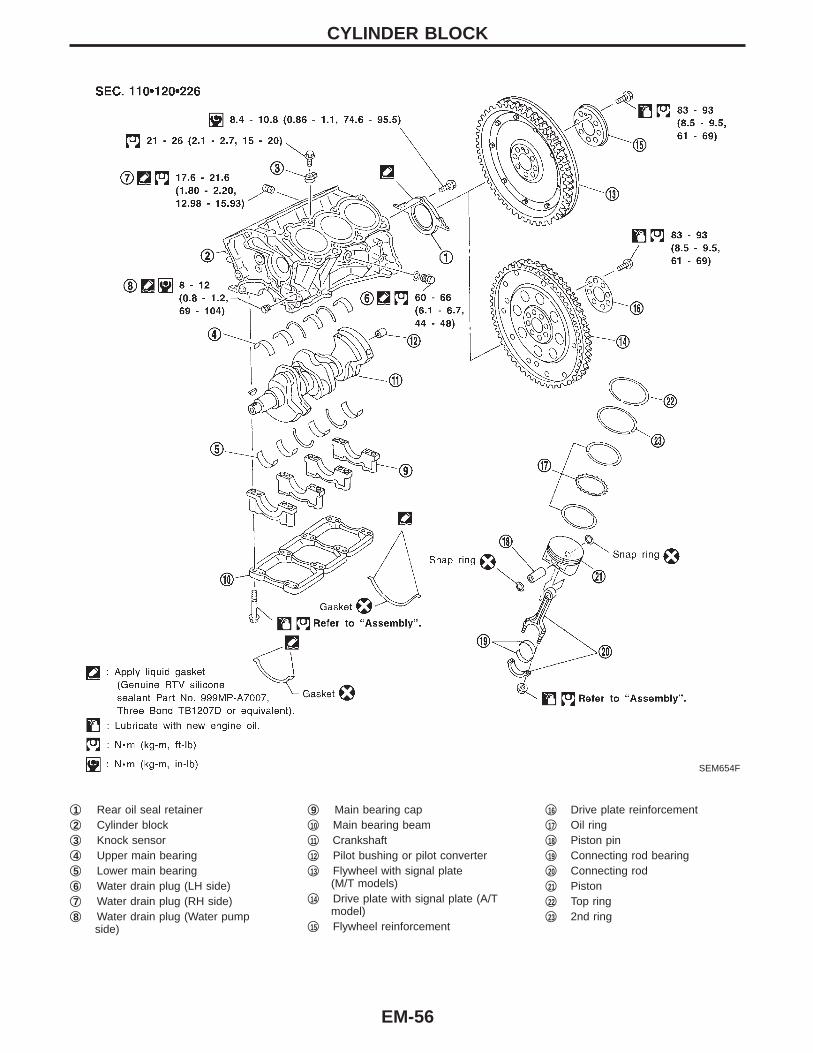
SEM654F
q1 Rear oil seal retainerq2 Cylinder blockq3 Knock sensorq4 Upper main bearingq5 Lower main bearingq6 Water drain plug (LH side)q7 Water drain plug (RH side)q8 Water drain plug (Water pump
side)
q9 Main bearing capq10 Main bearing beamq11 Crankshaftq12 Pilot bushing or pilot converterq13 Flywheel with signal plate
(M/T models)q14 Drive plate with signal plate (A/T
model)q15 Flywheel reinforcement
q16 Drive plate reinforcementq17 Oil ringq18 Piston pinq19 Connecting rod bearingq20 Connecting rodq21 Pistonq22 Top ringq23 2nd ring
CYLINDER BLOCK
EM-56
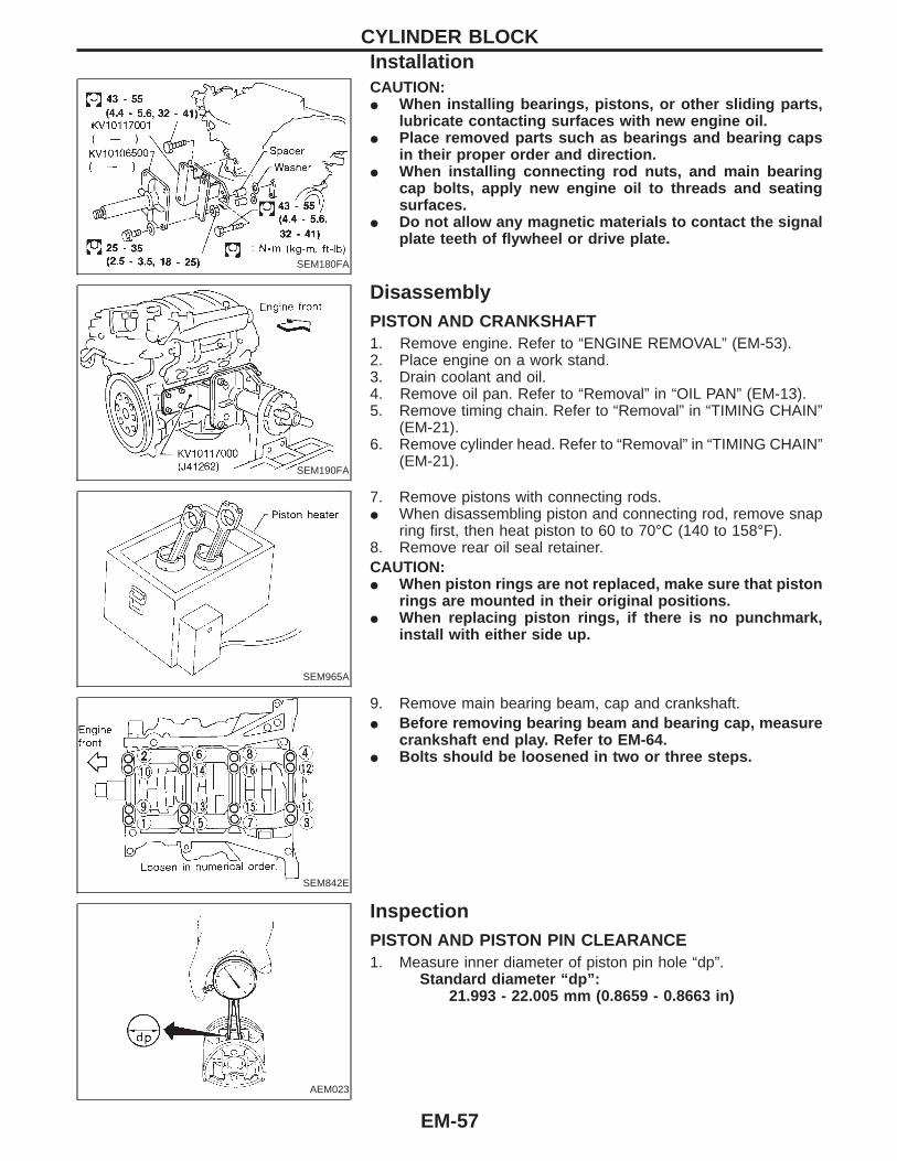
SEM180FA
CAUTION:I When installing bearings, pistons, or other sliding parts,
lubricate contacting surfaces with new engine oil.I Place removed parts such as bearings and bearing caps
in their proper order and direction.I When installing connecting rod nuts, and main bearing
cap bolts, apply new engine oil to threads and seatingsurfaces.
I Do not allow any magnetic materials to contact the signalplate teeth of flywheel or drive plate.
SEM190FA
DisassemblyPISTON AND CRANKSHAFT1. Remove engine. Refer to “ENGINE REMOVAL” (EM-53).2. Place engine on a work stand.3. Drain coolant and oil.4. Remove oil pan. Refer to “Removal” in “OIL PAN” (EM-13).5. Remove timing chain. Refer to “Removal” in “TIMING CHAIN”
(EM-21).6. Remove cylinder head. Refer to “Removal” in “TIMING CHAIN”
(EM-21).
SEM965A
7. Remove pistons with connecting rods.I When disassembling piston and connecting rod, remove snap
ring first, then heat piston to 60 to 70°C (140 to 158°F).8. Remove rear oil seal retainer.CAUTION:I When piston rings are not replaced, make sure that piston
rings are mounted in their original positions.I When replacing piston rings, if there is no punchmark,
install with either side up.
SEM842E
9. Remove main bearing beam, cap and crankshaft.I Before removing bearing beam and bearing cap, measure
crankshaft end play. Refer to EM-64.I Bolts should be loosened in two or three steps.
AEM023
InspectionPISTON AND PISTON PIN CLEARANCE1. Measure inner diameter of piston pin hole “dp”.
Standard diameter “dp”:21.993 - 22.005 mm (0.8659 - 0.8663 in)
CYLINDER BLOCKInstallation
EM-57

AEM024
2. Measure outer diameter of piston pin “Dp”.Standard diameter “Dp”:
21.989 - 22.001 mm (0.8657 - 0.8662 in)3. Calculate piston pin clearance.
Dp − dp = 0.002 - 0.006 mm (0.0001 - 0.0002 in)If it exceeds the above value, replace piston assembly with pin.
SEM024AA
PISTON RING SIDE CLEARANCESide clearance:
Top ring0.040 - 0.080 mm (0.0016 - 0.0031 in)
2nd ring0.030 - 0.070 mm (0.0012 - 0.0028 in)
Max. limit of side clearance:Top ring 0.11 mm (0.0043 in)2nd ring 0.1 mm (0.004 in)
If out of specification, replace piston and/or piston ring assembly.
SEM599A
PISTON RING END GAPEnd gap:
Top ring 0.22 - 0.32 mm (0.0087 - 0.0126 in)2nd ring 0.32 - 0.47 mm (0.0126 - 0.0185 in)Oil ring 0.20 - 0.60 mm (0.0079 - 0.0236 in)
Max. limit of ring gap:Top ring 0.55 mm (0.0217 in)2nd ring 0.85 mm (0.0335 in)Oil ring 0.95 mm (0.0374 in)
If out of specification, replace piston ring. If gap still exceeds thelimit even with a new ring, do the following. Rebore cylinder anduse oversized piston and piston rings.Refer to SDS (EM-72).When replacing the piston, check the cylinder block surface forscratches or seizure. If scratches or seizure is found, hone orreplace the cylinder block.
SEM038F
CONNECTING ROD BEND AND TORSIONBend:
Limit 0.15 mm (0.0059 in)per 100 mm (3.94 in) length
Torsion:Limit 0.30 mm (0.0118 in)per 100 mm (3.94 in) length
If it exceeds the limit, replace connecting rod assembly.
CYLINDER BLOCKInspection (Cont’d)
EM-58

SEM003F
SEM123C
CYLINDER BLOCK DISTORTION AND WEARI Clean upper surface of cylinder block.
Use a reliable straightedge and feeler gauge to check the flat-ness of cylinder block surface.Check along six positions shown in the figure.
Distortion limit: 0.10 mm (0.0039 in)I If out of specification, resurface it. The limit for cylinder block
resurfacing is determined by cylinder head resurfacing inengine.
Resurfacing limit:Amount of cylinder head resurfacing is “A”.Amount of cylinder block resurfacing is “B”.
The maximum limit is as follows:A + B = 0.2 mm (0.008 in)
Nominal cylinder block height from crankshaft center:214.95 - 215.05 mm (8.4626 - 8.4665 in)Refer to SDS (EM-71).
I If necessary, replace cylinder block.
SEM843E
SEM321AA
PISTON-TO-BORE CLEARANCE1. Using a bore gauge, measure cylinder bore for wear, out-of-
round and taper.Cylinder bore inner diameter
Grade No. Standard inner diameter Wear limit
No. 1 93.000 - 93.010 mm (3.6614 - 3.6618 in)
0.20 mm (0.0079 in)No. 2 93.011 - 93.020 mm (3.6618 - 3.6622 in)
No. 3 93.021 - 93.030 mm (3.6622 - 3.6626 in)
If it exceeds the limit, rebore all cylinders. Replace cylinder blockif necessary.
Out-of-round (X − Y):Limit 0.015 mm (0.0006 in)
Taper (A − B − C):Limit 0.015 mm (0.0006 in)
2. Check for scratches and seizure. If seizure is found, hone it.
CYLINDER BLOCKInspection (Cont’d)
EM-59
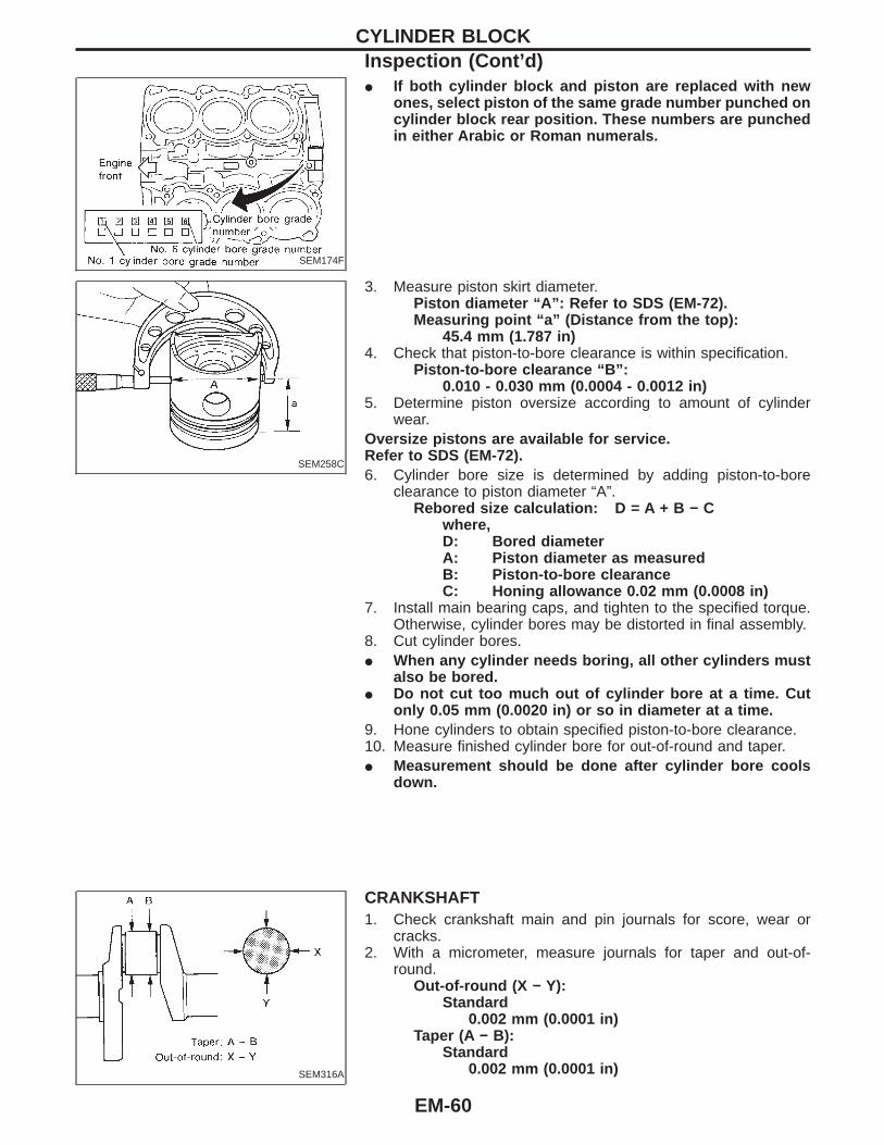
SEM174F
I If both cylinder block and piston are replaced with newones, select piston of the same grade number punched oncylinder block rear position. These numbers are punchedin either Arabic or Roman numerals.
SEM258C
3. Measure piston skirt diameter.Piston diameter “A”: Refer to SDS (EM-72).Measuring point “a” (Distance from the top):
45.4 mm (1.787 in)4. Check that piston-to-bore clearance is within specification.
Piston-to-bore clearance “B”:0.010 - 0.030 mm (0.0004 - 0.0012 in)
5. Determine piston oversize according to amount of cylinderwear.
Oversize pistons are available for service.Refer to SDS (EM-72).6. Cylinder bore size is determined by adding piston-to-bore
clearance to piston diameter “A”.Rebored size calculation: D = A + B − C
where,D: Bored diameterA: Piston diameter as measuredB: Piston-to-bore clearanceC: Honing allowance 0.02 mm (0.0008 in)
7. Install main bearing caps, and tighten to the specified torque.Otherwise, cylinder bores may be distorted in final assembly.
8. Cut cylinder bores.I When any cylinder needs boring, all other cylinders must
also be bored.I Do not cut too much out of cylinder bore at a time. Cut
only 0.05 mm (0.0020 in) or so in diameter at a time.9. Hone cylinders to obtain specified piston-to-bore clearance.10. Measure finished cylinder bore for out-of-round and taper.I Measurement should be done after cylinder bore cools
down.
SEM316A
CRANKSHAFT1. Check crankshaft main and pin journals for score, wear or
cracks.2. With a micrometer, measure journals for taper and out-of-
round.Out-of-round (X − Y):
Standard0.002 mm (0.0001 in)
Taper (A − B):Standard
0.002 mm (0.0001 in)
CYLINDER BLOCKInspection (Cont’d)
EM-60
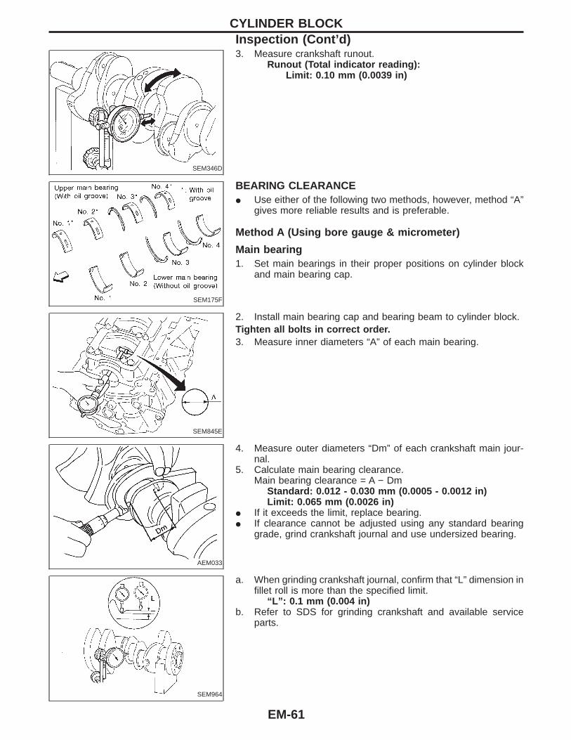
SEM346D
3. Measure crankshaft runout.Runout (Total indicator reading):
Limit: 0.10 mm (0.0039 in)
SEM175F
BEARING CLEARANCEI Use either of the following two methods, however, method “A”
gives more reliable results and is preferable.
Method A (Using bore gauge & micrometer)
Main bearing1. Set main bearings in their proper positions on cylinder block
and main bearing cap.
SEM845E
2. Install main bearing cap and bearing beam to cylinder block.Tighten all bolts in correct order.3. Measure inner diameters “A” of each main bearing.
AEM033
4. Measure outer diameters “Dm” of each crankshaft main jour-nal.
5. Calculate main bearing clearance.Main bearing clearance = A − Dm
Standard: 0.012 - 0.030 mm (0.0005 - 0.0012 in)Limit: 0.065 mm (0.0026 in)
I If it exceeds the limit, replace bearing.I If clearance cannot be adjusted using any standard bearing
grade, grind crankshaft journal and use undersized bearing.
SEM964
a. When grinding crankshaft journal, confirm that “L” dimension infillet roll is more than the specified limit.
“L”: 0.1 mm (0.004 in)b. Refer to SDS for grinding crankshaft and available service
parts.
CYLINDER BLOCKInspection (Cont’d)
EM-61
SEM176F
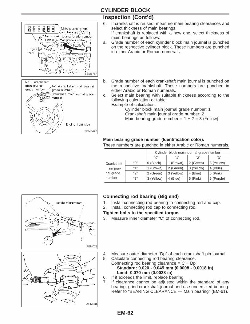
6. If crankshaft is reused, measure main bearing clearances andselect thickness of main bearings.If crankshaft is replaced with a new one, select thickness ofmain bearings as follows:
a. Grade number of each cylinder block main journal is punchedon the respective cylinder block. These numbers are punchedin either Arabic or Roman numerals.
SEM847E
b. Grade number of each crankshaft main journal is punched onthe respective crankshaft. These numbers are punched ineither Arabic or Roman numerals.
c. Select main bearing with suitable thickness according to thefollowing calculation or table.Example of calculation:
Cylinder block main journal grade number: 1Crankshaft main journal grade number: 2Main bearing grade number = 1 + 2 = 3 (Yellow)
Main bearing grade number (Identification color):These numbers are punched in either Arabic or Roman numerals.
Cylinder block main journal grade number
“0” “1” “2” “3”
Crankshaftmain jour-nal gradenumber
“0” 0 (Black) 1 (Brown) 2 (Green) 3 (Yellow)
“1” 1 (Brown) 2 (Green) 3 (Yellow) 4 (Blue)
“2” 2 (Green) 3 (Yellow) 4 (Blue) 5 (Pink)
“3” 3 (Yellow) 4 (Blue) 5 (Pink) 6 (Purple)
AEM027
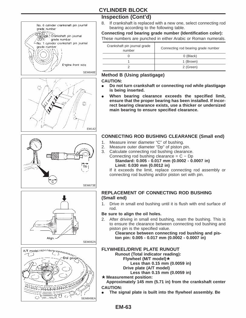
Connecting rod bearing (Big end)1. Install connecting rod bearing to connecting rod and cap.2. Install connecting rod cap to connecting rod.Tighten bolts to the specified torque.3. Measure inner diameter “C” of connecting rod.
AEM034
4. Measure outer diameter “Dp” of each crankshaft pin journal.5. Calculate connecting rod bearing clearance.
Connecting rod bearing clearance = C − DpStandard: 0.020 - 0.045 mm (0.0008 - 0.0018 in)Limit: 0.070 mm (0.0028 in)
6. If it exceeds the limit, replace bearing.7. If clearance cannot be adjusted within the standard of any
bearing, grind crankshaft journal and use undersized bearing.Refer to “BEARING CLEARANCE — Main bearing” (EM-61).
CYLINDER BLOCKInspection (Cont’d)
EM-62
SEM848E
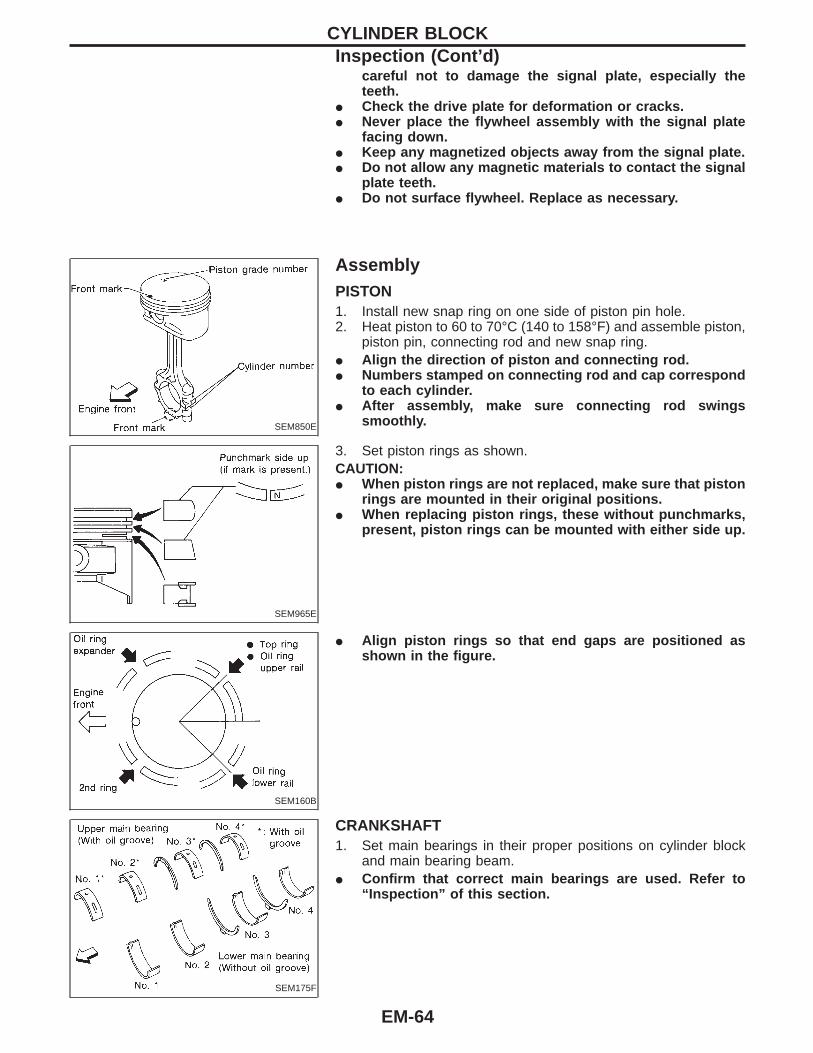
EM142
8. If crankshaft is replaced with a new one, select connecting rodbearing according to the following table.
Connecting rod bearing grade number (Identification color):These numbers are punched in either Arabic or Roman numerals.
Crankshaft pin journal gradenumber
Connecting rod bearing grade number
0 0 (Black)
1 1 (Brown)
2 2 (Green)
Method B (Using plastigage)CAUTION:I Do not turn crankshaft or connecting rod while plastigage
is being inserted.I When bearing clearance exceeds the specified limit,
ensure that the proper bearing has been installed. If incor-rect bearing clearance exists, use a thicker or undersizedmain bearing to ensure specified clearance.
SEM673E
CONNECTING ROD BUSHING CLEARANCE (Small end)1. Measure inner diameter “C” of bushing.2. Measure outer diameter “Dp” of piston pin.3. Calculate connecting rod bushing clearance.
Connecting rod bushing clearance = C − DpStandard: 0.005 - 0.017 mm (0.0002 - 0.0007 in)Limit: 0.030 mm (0.0012 in)
If it exceeds the limit, replace connecting rod assembly orconnecting rod bushing and/or piston set with pin.
SEM062A
REPLACEMENT OF CONNECTING ROD BUSHING(Small end)1. Drive in small end bushing until it is flush with end surface of
rod.Be sure to align the oil holes.2. After driving in small end bushing, ream the bushing. This is
to ensure the clearance between connecting rod bushing andpiston pin is the specified value.
Clearance between connecting rod bushing and pis-ton pin: 0.005 - 0.017 mm (0.0002 - 0.0007 in)
SEM849EA
FLYWHEEL/DRIVE PLATE RUNOUTRunout (Total indicator reading):
Flywheel (M/T model) ★Less than 0.15 mm (0.0059 in)
Drive plate (A/T model)Less than 0.15 mm (0.0059 in)
★ Measurement position:Approximately 145 mm (5.71 in) from the crankshaft center
CAUTION:I The signal plate is built into the flywheel assembly. Be
CYLINDER BLOCKInspection (Cont’d)
EM-63
careful not to damage the signal plate, especially theteeth.
I Check the drive plate for deformation or cracks.I Never place the flywheel assembly with the signal plate
facing down.I Keep any magnetized objects away from the signal plate.I Do not allow any magnetic materials to contact the signal
plate teeth.I Do not surface flywheel. Replace as necessary.
SEM850E
AssemblyPISTON1. Install new snap ring on one side of piston pin hole.2. Heat piston to 60 to 70°C (140 to 158°F) and assemble piston,
piston pin, connecting rod and new snap ring.I Align the direction of piston and connecting rod.I Numbers stamped on connecting rod and cap correspond
to each cylinder.I After assembly, make sure connecting rod swings
smoothly.
SEM965E
3. Set piston rings as shown.CAUTION:I When piston rings are not replaced, make sure that piston
rings are mounted in their original positions.I When replacing piston rings, these without punchmarks,
present, piston rings can be mounted with either side up.
SEM160B
I Align piston rings so that end gaps are positioned asshown in the figure.
SEM175F
CRANKSHAFT1. Set main bearings in their proper positions on cylinder block
and main bearing beam.I Confirm that correct main bearings are used. Refer to
“Inspection” of this section.
CYLINDER BLOCKInspection (Cont’d)
EM-64

SEM177F
2. Instructions for re-use of main bearing cap bolts.I A plastic zone tightening method is used for tightening
main bearing cap bolts. Measure d1 and d2 as shown inthe figure.d2: Select minimum diameter in the measuring area.If the difference between d1 and d2 exceeds the limit,replace the bolts with new ones.
Limit (d1 - d2): 0.11 mm (0.0043 in)
SEM851E
SEM852E
3. After installing crankshaft, main bearing cap, main bearingbeam and bearing cap bolts, tighten bearing cap bolts innumerical order.
I Tightening procedure(1) Tighten all bolts to 32 to 38 N ⋅m (3.3 to 3.9 kg-m, 24 to 28
ft-lb).(2) Turn all bolts 90 to 95 degrees clockwise with angle
wrench.I Prior to tightening bearing cap bolts, place bearing beam
in its proper position by shifting crankshaft in the axialdirection.
I After securing bearing cap bolts, make sure crankshaftturns smoothly by hand.
I Lubricate threads and seat surfaces of the bolts with newengine oil.
4. Measure crankshaft end play.Crankshaft end play:
Standard 0.10 - 0.25 mm (0.0039 - 0.0098 in)Limit 0.30 mm (0.0118 in)
If beyond the limit, replace bearing with a new one.5. Install connecting rod bearings in connecting rods and con-
necting rod caps.I Confirm that correct bearings are used.
SEM620
6. Install pistons with connecting rods.a. Install them into corresponding cylinders with Tool.I Be careful not to scratch cylinder wall with the connecting
rod.I Arrange so that front mark on piston head faces toward
engine front.
SEM956E
b. A plastic zone tightening method is used for tightening con-necting rod bolts and nuts. Check the old bolts for deformationbefore re-using them.
I Ensure that the connecting rod nut can be screwedsmoothly as far as the bolt thread end.
I If this is not possible, use slide calipers to measure theoutside diameter of the narrowest thread part of the boltat 16 mm (0.63 in) from the thread end. Replace the con-necting rod bolt and nut, if under the limit.
Standard: 7.90 - 8.00 mm (0.3110 - 0.3150 in)Limit: 7.75 mm (0.3051 in)
CYLINDER BLOCKAssembly (Cont’d)
EM-65

SEM953E
c. Install connecting rod caps.I Lubricate threads and seat surfaces with new engine oil.
Tighten connecting rod bearing cap nuts to the specifiedtorque.
Connecting rod bearing nut:(1) Tighten nuts to 19 to 21 N ⋅m
(1.9 to 2.1 kg-m, 14 to 15 ft-lb).(2) Turn nuts 90 to 95 degrees clockwise with
angle wrench.
SEM954E
7. Measure connecting rod side clearance.Connecting rod side clearance:
Standard0.20 - 0.35 mm (0.0079 - 0.0138 in)
Limit0.40 mm (0.0157 in)
If beyond the limit, replace connecting rod and/or crankshaft.8. Install rear oil seal retainer.
CYLINDER BLOCKAssembly (Cont’d)
EM-66

General SpecificationsCylinder arrangement V-6
Displacement cm3 (cu in) 2,988 (182.33)
Bore and stroke mm (in) 93 x 73.3 (3.66 x 2.886)
Valve arrangement DOHC
Firing order 1-2-3-4-5-6
Number of piston rings
Compression 2
Oil 1
Number of main bearings 4
Compression ratio 10.0
COMPRESSION PRESSUREUnit: kPa (kg/cm2, psi)/300 rpm
Compression pressure
Standard 1,275 (13.0, 185)
Minimum 981 (10.0, 142)
Differential limit betweencylinders
98 (1.0, 14)
Cylinder number
SEM713A
Inspection and AdjustmentCYLINDER HEAD
Unit: mm (in)
Standard Limit
Head surface distortionLess than
0.03 (0.0012)0.1 (0.004)
SEM949E
VALVEUnit: mm (in)
SEM188
Valve head diameter “D”
Intake 36.0 - 36.3 (1.417 - 1.429)
Exhaust 31.2 - 31.5 (1.228 - 1.240)
Valve length “L”
Intake 97.32 - 97.82 (3.8315 - 3.8512)
Exhaust 94.85 - 95.35 (3.7342 - 3.7539)
Valve stem diameter “d”
Intake 5.965 - 5.980 (0.2348 - 0.2354)
Exhaust 5.945 - 5.960 (0.2341 - 0.2346)
Valve seat angle “α”
Intake45°15′ - 45°45′
Exhaust
Valve margin “T”
Intake 0.95 - 1.25 (0.0374 - 0.0492)
Exhaust 1.15 - 1.45 (0.0453 - 0.0571)
Valve margin “T” limit More than 0.5 (0.020)
Valve stem end surface grindinglimit
Less than 0.2 (0.008)
Valve clearance (Cold)
Intake 0.26 - 0.34 (0.010 - 0.013)
Exhaust 0.29 - 0.37 (0.011 - 0.015)
SERVICE DATA AND SPECIFICATIONS (SDS)
EM-67

Valve clearanceUnit: mm (in)
Cold Hot* (reference data)
Intake0.26 - 0.34
(0.010 - 0.013)0.304 - 0.416
(0.012 - 0.016)
Exhaust0.29 - 0.37
(0.011 - 0.015)0.308 - 0.432
(0.012 - 0.017)
*: Approximately 80°C (176°F)
Available shims
Thickness mm (in) Identification mark
2.32 (0.0913) 232
2.33 (0.0917) 233
2.34 (0.0921) 234
2.35 (0.0925) 235
2.36 (0.0929) 236
2.37 (0.0933) 237
2.38 (0.0937) 238
2.39 (0.0941) 239
2.40 (0.0945) 240
2.41 (0.0949) 241
2.42 (0.0953) 242
2.43 (0.0957) 243
2.44 (0.0961) 244
2.45 (0.0965) 245
2.46 (0.0969) 246
2.47 (0.0972) 247
2.48 (0.0976) 248
2.49 (0.0980) 249
2.50 (0.0984) 250
2.51 (0.0988) 251
2.52 (0.0992) 252
2.53 (0.0996) 253
2.54 (0.1000) 254
2.55 (0.1004) 255
2.56 (0.1008) 256
2.57 (0.1012) 257
2.58 (0.1016) 258
2.59 (0.1020) 259
2.60 (0.1024) 260
2.61 (0.1028) 261
2.62 (0.1031) 262
2.63 (0.1035) 263
2.64 (0.1039) 264
Thickness mm (in) Identification mark
2.65 (0.1043) 265
2.66 (0.1047) 266
2.67 (0.1051) 267
2.68 (0.1055) 268
2.69 (0.1059) 269
2.70 (0.1063) 270
2.71 (0.1067) 271
2.72 (0.1071) 272
2.73 (0.1075) 273
2.74 (0.1079) 274
2.75 (0.1083) 275
2.76 (0.1087) 276
2.77 (0.1091) 277
2.78 (0.1094) 278
2.79 (0.1098) 279
2.80 (0.1102) 280
2.81 (0.1106) 281
2.82 (0.1110) 282
2.83 (0.1114) 283
2.84 (0.1118) 284
2.85 (0.1122) 285
2.86 (0.1126) 286
2.87 (0.1130) 287
2.88 (0.1134) 288
2.89 (0.1138) 289
2.90 (0.1142) 290
2.91 (0.1146) 291
2.92 (0.1150) 292
2.93 (0.1154) 293
2.94 (0.1157) 294
2.95 (0.1161) 295
SEM966E
SERVICE DATA AND SPECIFICATIONS (SDS)Inspection and Adjustment (Cont’d)
EM-68
Valve spring
Free height mm (in) 46.93 (1.8476)
PressureN (kg, lb) at height mm (in)
Standard454 (46.3, 102.1)at 27.55 (1.0846)
Limit427 (43.6, 96.0) at
27.55 (1.0846)
Out-of-square mm (in) Less than 2.0 (0.079)
Valve lifterUnit: mm (in)
Valve lifter outer diameter34.960 - 34.975
(1.3764 - 1.3770)
Lifter guide inner diameter35.000 - 35.021
(1.3780 - 1.3788)
Clearance between lifter and lifter guide0.025 - 0.061
(0.0010 - 0.0024)
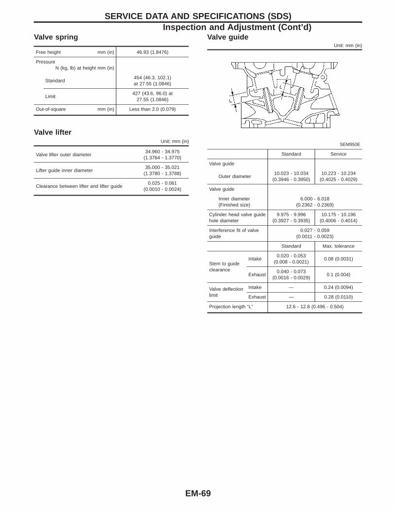
Valve guideUnit: mm (in)
SEM950E
Standard Service
Valve guide
Outer diameter10.023 - 10.034
(0.3946 - 0.3950)10.223 - 10.234
(0.4025 - 0.4029)
Valve guide
Inner diameter(Finished size)
6.000 - 6.018(0.2362 - 0.2369)
Cylinder head valve guidehole diameter
9.975 - 9.996(0.3927 - 0.3935)
10.175 - 10.196(0.4006 - 0.4014)
Interference fit of valveguide
0.027 - 0.059(0.0011 - 0.0023)
Standard Max. tolerance
Stem to guideclearance
Intake0.020 - 0.053
(0.008 - 0.0021)0.08 (0.0031)
Exhaust0.040 - 0.073
(0.0016 - 0.0029)0.1 (0.004)
Valve deflectionlimit
Intake — 0.24 (0.0094)
Exhaust — 0.28 (0.0110)
Projection length “L” 12.6 - 12.8 (0.496 - 0.504)
SERVICE DATA AND SPECIFICATIONS (SDS)Inspection and Adjustment (Cont’d)
EM-69

VALVE SEAT Unit: mm (in)
SEM021EA
SEM621F
Standard Service
Cylinder head seat recess diameter (D)In. 37.000 - 37.016 (1.4567 - 1.4573) 37.500 - 37.516 (1.4764 - 1.4770)
Ex. 32.200 - 32.216 (1.2677 - 1.2683) 32.700 - 32.716 (1.2874 - 1.2880)
Valve seat interference fitIn. 0.081 - 0.113 (0.0032 - 0.0044)
Ex. 0.064 - 0.096 (0.0025 - 0.0038)
Valve seat outer diameter (d)In. 37.097 - 37.113 (1.4605 - 1.4611) 37.597 - 37.613 (1.4802 - 1.4808)
Ex. 32.280 - 32.296 (1.2709 - 1.2715) 32.780 - 32.796 (1.2905 - 1.2912)
Height (h)In. 5.9 - 6.0 (0.232 - 0.236) 5.05 - 5.15 (0.1988 - 0.2028)
Ex. 5.9 - 6.0 (0.232 - 0.236) 4.95 - 5.05 (0.1949 - 0.1988)
Depth (H) 5.9 - 6.1 (0.232 - 0.240)
Depth (L)In. 41.07 - 41.67 (1.6169 - 1.6405)
Ex. 40.06 - 41.60 (1.5772 - 1.6378)
SERVICE DATA AND SPECIFICATIONS (SDS)Inspection and Adjustment (Cont’d)
EM-70
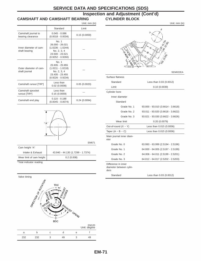
CAMSHAFT AND CAMSHAFT BEARINGUnit: mm (in)
Standard Limit
Camshaft journal tobearing clearance
0.045 - 0.086(0.0018 - 0.0034)
0.15 (0.0059)
Inner diameter of cam-shaft bearing
No. 126.000 - 26.021
(1.0236 - 1.0244)No. 2, 3, 4
23.500 - 23.521(0.9252 - 0.9260)
—
Outer diameter of cam-shaft journal
No. 125.935 - 25.955
(1.0211 - 1.0218)No. 2, 3, 4
23.435 - 23.455(0.9226 - 0.9234)
—
Camshaft runout [TIR*]Less than
0.02 (0.0008)0.05 (0.0020)
Camshaft sprocketrunout [TIR*]
Less than0.15 (0.0059)
—
Camshaft end play0.115 - 0.188
(0.0045 - 0.0074)0.24 (0.0094)
EM671
Cam height “A”
Intake & Exhaust 43.940 - 44.130 (1.7299 - 1.7374)
Wear limit of cam height 0.2 (0.008)
*Total indicator reading
Valve timing
EM120Unit: degree
a b c d e f
232 232 3 49 3 49
CYLINDER BLOCKUnit: mm (in)
SEM022EA
Surface flatness
Standard Less than 0.03 (0.0012)
Limit 0.10 (0.0039)
Cylinder bore
Inner diameter
Standard
Grade No. 1 93.000 - 93.010 (3.6614 - 3.6618)
Grade No. 2 93.011 - 93.020 (3.6618 - 3.6622)
Grade No. 3 93.021 - 93.030 (3.6622 - 3.6626)
Wear limit 0.20 (0.0079)
Out-of-round (X − Y) Less than 0.015 (0.0006)
Taper (A − B − C) Less than 0.015 (0.0006)
Main journal inner diam-eter
Grade No. 0 63.993 - 63.999 (2.5194 - 2.5196)
Grade No. 1 64.000 - 64.005 (2.5197 - 2.5199)
Grade No. 2 64.006 - 64.011 (2.5199 - 2.5201)
Grade No. 3 64.012 - 64.017 (2.5202 - 2.5203)
Difference in innerdiameter between cylin-ders
Standard Less than 0.03 (0.0012)
SERVICE DATA AND SPECIFICATIONS (SDS)Inspection and Adjustment (Cont’d)
EM-71

PISTON, PISTON RING AND PISTON PIN
Available pistonUnit: mm (in)
SEM882E
Piston skirt diameter “A”
Standard
Grade No. 1 92.979 - 92.988 (3.6606 - 3.6609)
Grade No. 2 92.988 - 93.000 (3.6609 - 3.6614)
Grade No. 3 93.000 - 93.009 (3.6614 - 3.6618)
0.20 (0.0079)oversize (Service)
93.180 - 93.210 (3.6685 - 3.6697)
“a” dimension 45.4 (1.787)
Piston pin hole diameter 21.993 - 22.005 (0.8659 - 0.8663)
Piston clearance to cylinderblock
0.010 - 0.030 (0.0004 - 0.0012)
Piston ringUnit: mm (in)
Standard Limit
Side clearance
Top0.040 - 0.080
(0.0016 - 0.0031)0.11 (0.0043)
2nd0.030 - 0.070
(0.0012 - 0.0028)0.1 (0.004)
End gap
Top0.22 - 0.32
(0.0087 - 0.0126)0.55 (0.0217)
2nd0.32 - 0.47
(0.0126 - 0.0185)0.85 (0.0335)
Oil (rail ring)0.20 - 0.60
(0.0079 - 0.0236)0.95 (0.0374)
Piston pinUnit: mm (in)
Piston pin outer diameter 21.989 - 22.001 (0.8657 - 0.8662)
Interference fit of piston pinto piston
0.002 - 0.006 (0.0001 - 0.0002)
Piston pin to connecting rodbushing clearance
0.005 - 0.017 (0.0002 - 0.0007)
*Values measured at ambient temperature of 20°C (68°F)
CONNECTING RODUnit: mm (in)
Center distance 147.60 - 147.70 (5.8110 - 5.8149)
Bend [per 100 (3.94)]
Limit 0.15 (0.0059)
Torsion [per 100 (3.94)]
Limit 0.30 (0.0118)
Connecting rod small endinner diameter
23.980 - 24.000 (0.9441 - 0.9449)
Piston pin bushing innerdiameter*
22.000 - 22.012 (0.8661 - 0.8666)
Connecting rod big end innerdiameter
48.000 - 48.013 (1.8898 - 1.8903)
Side clearance
Standard 0.20 - 0.35 (0.0079 - 0.0138)
Limit 0.40 (0.0157)
*After installing in connecting rod
SERVICE DATA AND SPECIFICATIONS (SDS)Inspection and Adjustment (Cont’d)
EM-72

CRANKSHAFTUnit: mm (in)
Main journal dia. “Dm”
Grade No. 0 59.969 - 59.975 (2.3610 - 2.3612)
Grade No. 1 59.963 - 59.969 (2.3607 - 2.3610)
Grade No. 2 59.957 - 59.963 (2.3605 - 2.3607)
Grade No. 3 59.951 - 59.957 (2.3603 - 2.3605)
Pin journal dia. “Dp”
Grade No. 0 44.968 - 44.974 (1.7704 - 1.7706)
Grade No. 1 44.962 - 44.968 (1.7702 - 1.7704)
Grade No. 2 44.956 - 44.962 (1.7699 - 1.7702)
Center distance “r” 36.61 - 36.69 (1.4413 - 1.4445)
Out-of-round (X − Y)
Standard Less than 0.002 (0.0001)
Taper (A − B)
Standard Less than 0.002 (0.0001)
Runout [TIR]
Limit Less than 0.10 (0.0039)
Free end play
Standard 0.10 - 0.25 (0.0039 - 0.0098)
Limit 0.30 (0.0118)
SEM645
EM715
AVAILABLE MAIN BEARING
SEM175F
Gradenumber
Thickness “T”mm (in)
Width “W”mm (in)
Identificationcolor
02.000 - 2.003
(0.0787 - 0.0789)
19.9 - 20.1(0.783 - 0.791)
Black
12.003 - 2.006
(0.0789 - 0.0790)Brown
22.006 - 2.009
(0.0790 - 0.0791)Green
32.009 - 2.012
(0.0791 - 0.0792)Yellow
42.012 - 2.015
(0.0792 - 0.0793)Blue
52.015 - 2.018
(0.0793 - 0.0794)Pink
62.018 - 2.021
(0.0794 - 0.0796)Purple
UndersizeUnit: mm (in)
ThicknessMain journal
diameter “Dm”
0.25(0.0098)
2.132 - 2.140(0.0839 - 0.0843)
Grind so that bearingclearance is the speci-fied value.
SERVICE DATA AND SPECIFICATIONS (SDS)Inspection and Adjustment (Cont’d)
EM-73
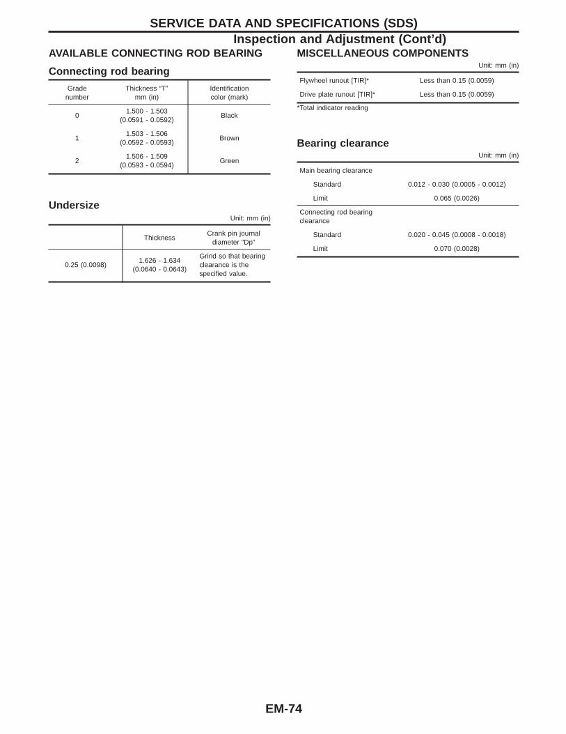
AVAILABLE CONNECTING ROD BEARING
Connecting rod bearing
Gradenumber
Thickness “T”mm (in)
Identificationcolor (mark)
01.500 - 1.503
(0.0591 - 0.0592)Black
11.503 - 1.506
(0.0592 - 0.0593)Brown
21.506 - 1.509
(0.0593 - 0.0594)Green
UndersizeUnit: mm (in)
ThicknessCrank pin journal
diameter “Dp”
0.25 (0.0098)1.626 - 1.634
(0.0640 - 0.0643)
Grind so that bearingclearance is thespecified value.
MISCELLANEOUS COMPONENTSUnit: mm (in)
Flywheel runout [TIR]* Less than 0.15 (0.0059)
Drive plate runout [TIR]* Less than 0.15 (0.0059)
*Total indicator reading
Bearing clearanceUnit: mm (in)
Main bearing clearance
Standard 0.012 - 0.030 (0.0005 - 0.0012)
Limit 0.065 (0.0026)
Connecting rod bearingclearance
Standard 0.020 - 0.045 (0.0008 - 0.0018)
Limit 0.070 (0.0028)
SERVICE DATA AND SPECIFICATIONS (SDS)Inspection and Adjustment (Cont’d)
EM-74
ENGINE MECHSANICAL
SECTIONEMCONTENTS
PRECAUTIONS ...............................................................2Parts Requiring Angular Tightening.............................2Liquid Gasket Application Procedure ..........................2
PREPARATION ................................................................3Special Service Tools ..................................................3Commercial Service Tools ...........................................5
NOISE, VIBRATION AND HARSHNESS (NVH)TROUBLESHOOTING .....................................................6
NVH Troubleshooting Chart — Engine Noise .............7OUTER COMPONENT PARTS .......................................8COMPRESSION PRESSURE........................................12
Measurement of Compression Pressure...................12OIL PAN .........................................................................13
Removal.....................................................................13Installation..................................................................16
TIMING CHAIN ..............................................................19Removal.....................................................................21Inspection...................................................................28Installation..................................................................28
OIL SEAL REPLACEMENT ..........................................33
CYLINDER HEAD ..........................................................36Removal.....................................................................37Disassembly...............................................................37Inspection...................................................................39Assembly ...................................................................44Installation..................................................................44
VALVE CLEARANCE ....................................................49Checking ....................................................................49Adjusting ....................................................................50
ENGINE REMOVAL .......................................................53Removal.....................................................................54Installation..................................................................55
CYLINDER BLOCK .......................................................56Disassembly...............................................................57Inspection...................................................................57Assembly ...................................................................64
SERVICE DATA AND SPECIFICATIONS (SDS) ..........67General Specifications...............................................67Inspection and Adjustment ........................................67


![Determinant (3A) - Wikimedia...Determinant (3A) 5 Young Won Lim 03/09/2015 Rule of Sarrus (1) [a11 a12 a13a21 a22 a23 a31 a32 a33] a11 a12 a21 a22 a31 a32 [ a11 a12 a13 a21 a22 a23](https://img.pdfslide.us/doc/110x75/5f0843897e708231d4212583/determinant-3a-wikimedia-determinant-3a-5-young-won-lim-03092015-rule.jpg)