Embed Size (px)
Citation preview

Report onProposals
2012 Annual Revision Cycle
NOTE: The proposed NFPA documents addressed in this Report on
Proposals (ROP) and in a follow-up Report on Comments (ROC) will only be
presented for action when proper Amending Motions have been submitted to
the NFPA by the deadline of April 6, 2012. The June 2012 NFPA Conference
& Expo will be held June 11–14, 2012, at the Mandalay Bay Convention
Center, Las Vegas, NV. During the meeting, the Association Technical
Meeting (Tech Session) will be held June 13–14, 2012. Documents that
receive no motions will not be presented at the meeting and instead will be
forwarded directly to the Standards Council for action on issuance. For more
information on the rules and for up-to-date information on schedules and
deadlines for processing NFPA documents, check the NFPA website
(www.nfpa.org) or contact NFPA Standards Administration.
ISSN 1079-5332 Copyright © 2011 All Rights Reserved
NFPA and National Fire Protection Association are registered trademarks of the National Fire Protection Association, Quincy, MA 02169.
National Fire Protection Association®1 BATTERYMARCH PARK, QUINCY, MA 02169-7471
A compilation of NFPA® TechnicalCommittee Reports on Proposals for public review and comment
Public Comment Deadline: August 30, 2011

Information on NFPA Codes and Standards Development
I. Applicable Regulations. The primary rules governing the processing of NFPA documents (codes, standards, recommended practices, and guides) are the NFPA Regulations Governing Committee Projects (Regs). Other applicable rules include NFPA Bylaws, NFPA Technical Meeting Convention Rules, NFPA Guide for the Conduct of Participants in the NFPA Standards Development Process, and the NFPA Regulations Governing Petitions to the Board of Directors from Decisions of the Standards Council. Most of these rules and regulations are contained in the NFPA Directory. For copies of the Directory, contact Codes and Standards Administration at NFPA Headquarters; all these documents are also available on the NFPA website at “www.nfpa.org.”
The following is general information on the NFPA process. All participants, however, should refer to the actual rules and regulations for a full understanding of this process and for the criteria that govern participation.
II. Technical Committee Report. The Technical Committee Report is defined as “the Report of the Technical Committee and Technical Correlating Committee (if any) on a document consisting of the ROP and ROC.” A Technical Committee Report consists of the Report on Proposals (ROP), as modified by the Report on Comments (ROC), published by the Association.
III. Step 1: Report on Proposals (ROP). The ROP is defined as “a report to the Association on the actions taken by Technical Committees and/or Technical Correlating Committees, accompanied by a ballot statement and one or more proposals on text for a new document or to amend an existing document.” Any objection to an action in the ROP must be raised through the filing of an appropriate Comment for consideration in the ROC or the objection will be considered resolved.
IV. Step 2: Report on Comments (ROC). The ROC is defined as “a report to the Association on the actions taken by Technical Committees and/or Technical Correlating Committees accompanied by a ballot statement and one or more comments resulting from public review of the Report on Proposals (ROP).” The ROP and the ROC together constitute the Technical Committee Report. Any outstanding objection following the ROC must be raised through an appropriate Amending Motion at the Association Technical Meeting or the objection will be considered resolved.
V. Step 3a: Action at Association Technical Meeting. Following the publication of the ROC, there is a period during which those wishing to make proper Amending Motions on the Technical Committee Reports must signal their intention by submitting a Notice of Intent to Make a Motion. Documents that receive notice of proper Amending Motions (Certified Amending Motions) will be presented for action at the annual June Association Technical Meeting. At the meeting, the NFPA membership can consider and act on these Certified Amending Motions as well as Follow-up Amending Motions, that is, motions that become necessary as a result of a previous successful Amending Motion. (See 4.6.2 through 4.6.9 of Regs for a summary of the available Amending Motions and who may make them.) Any outstanding objection following action at an Association Technical Meeting (and any further Technical Committee consideration following successful Amending Motions, see Regs at 4.7) must be raised through an appeal to the Standards Council or it will be considered to be resolved.
VI. Step 3b: Documents Forwarded Directly to the Council. Where no Notice of Intent to Make a Motion (NITMAM) is received and certified in accordance with the Technical Meeting Convention Rules, the document is forwarded directly to the Standards Council for action on issuance. Objections are deemed to be resolved for these documents.
VII. Step 4a: Council Appeals. Anyone can appeal to the Standards Council concerning procedural or substantive matters related to the development, content, or issuance of any document of the Association or on matters within the purview of the authority of the Council, as established by the Bylaws and as determined by the Board of Directors. Such appeals must be in written form and filed with the Secretary of the Standards Council (see 1.6 of Regs). Time constraints for filing an appeal must be in accordance with 1.6.2 of the Regs. Objections are deemed to be resolved if not pursued at this level.
VIII. Step 4b: Document Issuance. The Standards Council is the issuer of all documents (see Article 8 of Bylaws). The Council acts on the issuance of a document presented for action at an Association Technical Meeting within 75 days from the date of the recommendation from the Association Technical Meeting, unless this period is extended by the Council (see 4.8 of Regs). For documents forwarded directly to the Standards Council, the Council acts on the issuance of the document at its next scheduled meeting, or at such other meeting as the Council may determine (see 4.5.6 and 4.8 of Regs).
IX. Petitions to the Board of Directors. The Standards Council has been delegated the responsibility for the administration of the codes and standards development process and the issuance of documents. However, where extraordinary circumstances requiring the intervention of the Board of Directors exist, the Board of Directors may take any action necessary to fulfill its obligations to preserve the integrity of the codes and standards development process and to protect the interests of the Association. The rules for petitioning the Board of Directors can be found in the Regulations Governing Petitions to the Board of Directors from Decisions of the Standards Council and in 1.7 of the Regs.
X. For More Information. The program for the Association Technical Meeting (as well as the NFPA website as information becomes available) should be consulted for the date on which each report scheduled for consideration at the meeting will be presented. For copies of the ROP and ROC as well as more information on NFPA rules and for up-to-date information on schedules and deadlines for processing NFPA documents, check the NFPA website (www.nfpa.org) or contact NFPA Codes & Standards Administration at (617) 984-7246.

2012 Annual Revision Cycle ROP Contents
by NFPA Numerical Designation
Note: Documents appear in numerical order.
NFPA No. Type Action Title Page No.
13 P Standard for the Installation of Sprinkler Systems ......................................................................................... 13-1 13D P Standard for the Installation of Sprinkler Systems in One- and Two-Family Dwellings and Manufactured Homes ............................................................................................................................ 13D-1 13R P Standard for the Installation of Sprinkler Systems in Residential Occupancies up to and Including Four Stories in Height ................................................................................................. 13R-1 20 P Standard for the Installation of Stationary Pumps for Fire Protection ........................................................... 20-1 24 P Standard for the Installation of Private Fire Service Mains and Their Appurtenances ................................ .24-1 51 P Standard for the Design and Installation of Oxygen-Fuel Gas Systems for Welding, Cutting, and Allied Processes………………………………………………………………………………51-1 55 P Compressed Gases and Cryogenic Fluids Code…………………………………………………………….55-1 61 P Standard for the Prevention of Fires and Dust Explosions in Agricultural and Food Processing Facilities………………………………………………………………………...……61-1 72® P National Fire Alarm and Signaling Code® ..................................................................................................... 72-1 80 P Standard for Fire Doors and Other Opening Protectives ................................................................................ 80-1
101A P Guide on Alternative Approaches to Life Safety ...................................................................................... 101A-1 105 P Standard for the Installation of Smoke Door Assemblies and Other Opening Protectives ...................................................................................................................................... 105-1 110 P Standard for Emergency and Standby Power Systems ................................................................................. 110-1 111 P Standard on Stored Electrical Energy Emergency and Standby Power Systems......................................... 111-1
291 P Recommended Practice for Fire Flow Testing and Marking of Hydrants ................................................... 291-1 301 P Code for Safety to Life from Fire on Merchant Vessels .............................................................................. 301-1 400 P Hazardous Materials Code ............................................................................................................................ 400-1 402 P Guide for Aircraft Rescue and Fire-Fighting Operations ............................................................................. 402-1 415 P Standard on Airport Terminal Buildings, Fueling Ramp Drainage, and Loading Walkways ..................... 415-1 424 P Guide for Airport/Community Emergency Planning .................................................................................. 424-1 450 P Guide for Emergency Medical Services and Systems .................................................................................. 450-1 472 P Standard for Competence of Responders to Hazardous Materials/Weapons of Mass Destruction Incidents ...................................................................................................................... 472-1 473 P Standard for Competencies for EMS Personnel Responding to Hazardous Materials/Weapons of Mass Destruction Incidents ...................................................................................... 473-1 555 P Guide on Methods for Evaluating Potential for Room Flashover…………………………………………555-1

654 P Standard for the Prevention of Fire and Dust Explosions from the Manufacturing, Processing, and Handling of Combustible Particulate Solids………………………………………………………………654-1 1001 P Standard for Fire Fighter Professional Qualifications……………………………………………………1001-1 1122 P Code for Model Rocketry…………………………...………………………………………………….…1122-1 1124 P Code for the Manufacture, Transportation, Storage, and Retail Sales of Fireworks and Pyrotechnic Articles………………………………………………………………………1124-1 1127 P Code for High Power Rocketry………………………………………………………………………...…1127-1 1128DS N Draft Standard for Standard Method of Fire Test for Flame
Breaks…………………………………………………………………………………………………1128DS-1 1129DS N Draft Standard for Standard Method of Fire Test for Covered Fuse on Consumer
Fireworks………………………………………………………………………………………………1129DS-1 1144 P Standard for Reducing Structure Ignition Hazards from Wildland Fire ……….…………………………1144-1 1221 P Standard for the Installation, Maintenance, and Use of Emergency Services Communications Systems…….……………………………………………………1221-1 1500 P Standard on Fire Department Occupational Safety and Health
Program……………………………………………..……………………………………………………1500-1 1582 P Standard on Comprehensive Occupational Medical Program for Fire Departments……………………………………………………………………………1582-1 1801 P Standard on Thermal Imagers for the Fire Service….……………………………………………………1801-1 1917 N Standard for Automotive Ambulances……………..…………………………………………..…………1917-1
TYPES OF ACTION
P Partial Revision C Complete Revision N New Document R Reconfirmation W Withdrawal
iii
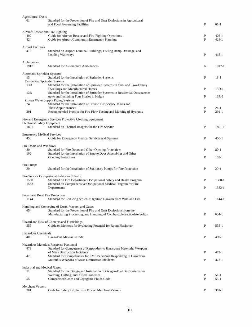
Agricultural Dusts 61 Standard for the Prevention of Fire and Dust Explosions in Agricultural and Food Processing Facilities P 61-1 Aircraft Rescue and Fire Fighting 402 Guide for Aircraft Rescue and Fire-Fighting Operations P 402-1 424 Guide for Airport/Community Emergency Planning P 424-1 Airport Facilities 415 Standard on Airport Terminal Buildings, Fueling Ramp Drainage, and Loading Walkways P 415-1 Ambulances 1917 Standard for Automotive Ambulances N 1917-1 Automatic Sprinkler Systems 13 Standard for the Installation of Sprinkler Systems P 13-1 Residential Sprinkler Systems 13D Standard for the Installation of Sprinkler Systems in One- and Two-Family Dwellings and Manufactured Homes P 13D-1 13R Standard for the Installation of Sprinkler Systems in Residential Occupancies up to and Including Four Stories in Height P 13R-1 Private Water Supply Piping Systems 24 Standard for the Installation of Private Fire Service Mains and Their Appurtenances P 24-1 291 Recommended Practice for Fire Flow Testing and Marking of Hydrants P 291-1 Fire and Emergency Services Protective Clothing Equipment Electronic Safety Equipment 1801 Standard on Thermal Imagers for the Fire Service P 1801-1 Emergency Medical Services 450 Guide for Emergency Medical Services and Systems P 450-1 Fire Doors and Windows 80 Standard for Fire Doors and Other Opening Protectives P 80-1 105 Standard for the Installation of Smoke Door Assemblies and Other Opening Protectives P 105-1 Fire Pumps 20 Standard for the Installation of Stationary Pumps for Fire Protection P 20-1 Fire Service Occupational Safety and Health 1500 Standard on Fire Department Occupational Safety and Health Program P 1500-1 1582 Standard on Comprehensive Occupational Medical Program for Fire Departments P 1582-1 Forest and Rural Fire Protection 1144 Standard for Reducing Structure Ignition Hazards from Wildland Fire P 1144-1 Handling and Conveying of Dusts, Vapors, and Gases 654 Standard for the Prevention of Fire and Dust Explosions from the Manufacturing Processing, and Handling of Combustible Particulate Solids P 654-1 Hazard and Risk of Contents and Furnishings 555 Guide on Methods for Evaluating Potential for Room Flashover P 555-1 Hazardous Chemicals 400 Hazardous Materials Code P 400-1 Hazardous Materials Response Personnel 472 Standard for Competence of Responders to Hazardous Materials/ Weapons of Mass Destruction Incidents P 472-1 473 Standard for Competencies for EMS Personnel Responding to Hazardous Materials/Weapons of Mass Destruction Incidents P 473-1 Industrial and Medical Gases 51 Standard for the Design and Installation of Oxygen-Fuel Gas Systems for Welding, Cutting, and Allied Processes P 51-1 55 Compressed Gases and Cryogenic Fluids Code P 55-1 Merchant Vessels 301 Code for Safety to Life from Fire on Merchant Vessels P 301-1

iii
National Electrical Code Emergency Power Supplies 110 Standard for Emergency and Standby Power Systems P 110-1 111 Standard on Stored Electrical Energy Emergency and Standby Power Systems P 111-1 Professional Qualifications Fire Fighter Professional Qualifications 1001 Standard for Fire Fighter Professional Qualifications P 1001-1 Public Emergency Service Communication 1221 Standard for the Installation, Maintenance, and Use of Emergency Services Communications Systems P 1221-1 Pyrotechnics 1122 Code for Model Rocketry P 1122-1 1124 Code for the Manufacture, Transportation, Storage, and Retail Sales of Fireworks and Pyrotechnic Articles P 1124-1 1127 Code for High Power Rocketry P 1127-1 1128DS Draft Standard for Standard Method of Fire Tests for Flame Breaks N 1128DS-1 1129DS Draft Standard for Standard Method of Fire Test for Covered Fuse on Consumer Fireworks N 1129DS-1 Safety to Life Alternative Approaches to Life Safety 101A Guide on Alternative Approaches to Life Safety P 101A-1 Signaling Systems for the Protection of Life and Property 72 National Fire Alarm Code P 72-1
v
COMMITTEE MEMBER CLASSIFICATIONS1,2,3,4
The following classifications apply to Committee members and represent their principal interest in the activity of the Committee. 1. M Manufacturer: A representative of a maker or marketer of a product, assembly, or system, or portion thereof,
that is affected by the standard. 2. U User: A representative of an entity that is subject to the provisions of the standard or that voluntarily uses the
standard. 3. IM Installer/Maintainer: A representative of an entity that is in the business of installing or maintaining a product,
assembly, or system affected by the standard. 4. L Labor: A labor representative or employee concerned with safety in the workplace. 5. RT Applied Research/Testing Laboratory: A representative of an independent testing laboratory or independent
applied research organization that promulgates and/or enforces standards. 6. E Enforcing Authority: A representative of an agency or an organization that promulgates and/or enforces
standards. 7. I Insurance: A representative of an insurance company, broker, agent, bureau, or inspection agency. 8. C Consumer: A person who is or represents the ultimate purchaser of a product, system, or service affected by the
standard, but who is not included in (2). 9. SE Special Expert: A person not representing (1) through (8) and who has special expertise in the scope of the
standard or portion thereof. NOTE 1: “Standard” connotes code, standard, recommended practice, or guide. NOTE 2: A representative includes an employee. NOTE 3: While these classifications will be used by the Standards Council to achieve a balance for Technical Committees, the Standards Council may determine that new classifications of member or unique interests need representation in order to foster the best possible Committee deliberations on any project. In this connection, the Standards Council may make such appointments as it deems appropriate in the public interest, such as the classification of “Utilities” in the National Electrical Code Committee. NOTE 4: Representatives of subsidiaries of any group are generally considered to have the same classification as the parent organization.

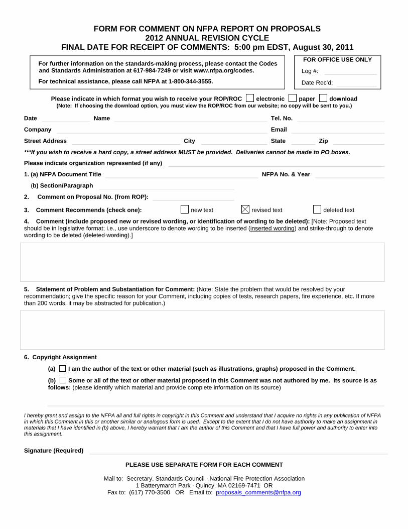
FORM FOR COMMENT ON NFPA REPORT ON PROPOSALS 2012 ANNUAL REVISION CYCLE
FINAL DATE FOR RECEIPT OF COMMENTS: 5:00 pm EDST, August 30, 2011
For further information on the standards-making process, please contact the Codes and Standards Administration at 617-984-7249 or visit www.nfpa.org/codes.
For technical assistance, please call NFPA at 1-800-344-3555.
FOR OFFICE USE ONLY
Log #:
Date Rec’d:
Please indicate in which format you wish to receive your ROP/ROC electronic paper download (Note: If choosing the download option, you must view the ROP/ROC from our website; no copy will be sent to you.)
Date 8/1/200X Name John B. Smith Tel. No. 253-555-1234
Company Email
Street Address 9 Seattle St. City Tacoma State WA Zip 98402
***If you wish to receive a hard copy, a street address MUST be provided. Deliveries cannot be made to PO boxes.
Please indicate organization represented (if any) Fire Marshals Assn. of North America
1. (a) NFPA Document Title National Fire Alarm Code NFPA No. & Year NFPA 72, 200X ed.
(b) Section/Paragraph 4.4.1.1
2. Comment on Proposal No. (from ROP): 72-7
3. Comment Recommends (check one): new text revised text deleted text
4. Comment (include proposed new or revised wording, or identification of wording to be deleted): [Note: Proposed text should be in legislative format; i.e., use underscore to denote wording to be inserted (inserted wording) and strike-through to denote wording to be deleted (deleted wording).]
Delete exception.
5. Statement of Problem and Substantiation for Comment: (Note: State the problem that would be resolved by your recommendation; give the specific reason for your Comment, including copies of tests, research papers, fire experience, etc. If more than 200 words, it may be abstracted for publication.)
A properly installed and maintained system should be free of ground faults. The occurrence of one or more ground faults should be required to cause a ‘trouble’ signal because it indicates a condition that could contribute to future malfunction of the system. Ground fault protection has been widely available on these systems for years and its cost is negligible. Requiring it on all systems will promote better installations, maintenance and reliability.
6. Copyright Assignment
(a) I am the author of the text or other material (such as illustrations, graphs) proposed in the Comment.
(b) Some or all of the text or other material proposed in this Comment was not authored by me. Its source is as follows: (please identify which material and provide complete information on its source)
I hereby grant and assign to the NFPA all and full rights in copyright in this Comment and understand that I acquire no rights in any publication of NFPA in which this Comment in this or another similar or analogous form is used. Except to the extent that I do not have authority to make an assignment in materials that I have identified in (b) above, I hereby warrant that I am the author of this Comment and that I have full power and authority to enter into this assignment.
Signature (Required)
PLEASE USE SEPARATE FORM FOR EACH COMMENT
Mail to: Secretary, Standards Council · National Fire Protection Association 1 Batterymarch Park · Quincy, MA 02169-7471 OR
Fax to: (617) 770-3500 OR Email to: [email protected]
FORM FOR COMMENT ON NFPA REPORT ON PROPOSALS 2012 ANNUAL REVISION CYCLE
FINAL DATE FOR RECEIPT OF COMMENTS: 5:00 pm EDST, August 30, 2011
For further information on the standards-making process, please contact the Codes and Standards Administration at 617-984-7249 or visit www.nfpa.org/codes.
For technical assistance, please call NFPA at 1-800-344-3555.
FOR OFFICE USE ONLY
Log #:
Date Rec’d:
Please indicate in which format you wish to receive your ROP/ROC electronic paper download (Note: If choosing the download option, you must view the ROP/ROC from our website; no copy will be sent to you.)
Date Name Tel. No.
Company Email
Street Address City State Zip
***If you wish to receive a hard copy, a street address MUST be provided. Deliveries cannot be made to PO boxes.
Please indicate organization represented (if any)
1. (a) NFPA Document Title NFPA No. & Year
(b) Section/Paragraph
2. Comment on Proposal No. (from ROP):
3. Comment Recommends (check one): new text revised text deleted text
4. Comment (include proposed new or revised wording, or identification of wording to be deleted): [Note: Proposed text should be in legislative format; i.e., use underscore to denote wording to be inserted (inserted wording) and strike-through to denote wording to be deleted (deleted wording).]
5. Statement of Problem and Substantiation for Comment: (Note: State the problem that would be resolved by your recommendation; give the specific reason for your Comment, including copies of tests, research papers, fire experience, etc. If more than 200 words, it may be abstracted for publication.)
6. Copyright Assignment
(a) I am the author of the text or other material (such as illustrations, graphs) proposed in the Comment.
(b) Some or all of the text or other material proposed in this Comment was not authored by me. Its source is as follows: (please identify which material and provide complete information on its source)
I hereby grant and assign to the NFPA all and full rights in copyright in this Comment and understand that I acquire no rights in any publication of NFPA in which this Comment in this or another similar or analogous form is used. Except to the extent that I do not have authority to make an assignment in materials that I have identified in (b) above, I hereby warrant that I am the author of this Comment and that I have full power and authority to enter into this assignment.
Signature (Required)
PLEASE USE SEPARATE FORM FOR EACH COMMENT
Mail to: Secretary, Standards Council · National Fire Protection Association 1 Batterymarch Park · Quincy, MA 02169-7471 OR
Fax to: (617) 770-3500 OR Email to: [email protected]
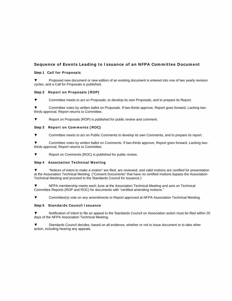
Sequence of Events Leading to Issuance of an NFPA Committee Document
Step 1 Call for Proposals
▼ Proposed new document or new edition of an existing document is entered into one of two yearly revision cycles, and a Call for Proposals is published.
Step 2 Report on Proposals (ROP)
▼ Committee meets to act on Proposals, to develop its own Proposals, and to prepare its Report.
▼ Committee votes by written ballot on Proposals. If two-thirds approve, Report goes forward. Lacking two-thirds approval, Report returns to Committee.
▼ Report on Proposals (ROP) is published for public review and comment.
Step 3 Report on Comments (ROC)
▼ Committee meets to act on Public Comments to develop its own Comments, and to prepare its report.
▼ Committee votes by written ballot on Comments. If two-thirds approve, Report goes forward. Lacking two-thirds approval, Report returns to Committee.
▼ Report on Comments (ROC) is published for public review.
Step 4 Association Technical Meeting
▼ “Notices of intent to make a motion” are filed, are reviewed, and valid motions are certified for presentation at the Association Technical Meeting. (“Consent Documents” that have no certified motions bypass the Association Technical Meeting and proceed to the Standards Council for issuance.)
▼ NFPA membership meets each June at the Association Technical Meeting and acts on Technical Committee Reports (ROP and ROC) for documents with “certified amending motions.”
▼ Committee(s) vote on any amendments to Report approved at NFPA Association Technical Meeting.
Step 5 Standards Council Issuance
▼ Notification of intent to file an appeal to the Standards Council on Association action must be filed within 20 days of the NFPA Association Technical Meeting.
▼ Standards Council decides, based on all evidence, whether or not to issue document or to take other action, including hearing any appeals.
The Association Technical Meeting
The process of public input and review does not end with the publication of the ROP and ROC. Following the completion of the Proposal and Comment periods, there is yet a further opportunity for debate and discussion through the Association Technical Meeting that takes place at the NFPA Annual Meeting.
The Association Technical Meeting provides an opportunity for the final Technical Committee Report (i.e., the ROP and ROC) on each proposed new or revised code or standard to be presented to the NFPA membership for the debate and consideration of motions to amend the Report. The specific rules for the types of motions that can be made and who can make them are set forth in the NFPA Regulations Governing Committee Projects (Regs), which should always be consulted by those wishing to bring an issue before the membership at an Association Technical Meeting. The following presents some of the main features of how a Report is handled.
The Filing of a Notice of Intent to Make a Motion. Before making an allowable motion at an Association Technical Meeting, the intended maker of the motion must file, in advance of the session, and within the published deadline, a Notice of Intent to Make a Motion. A Motions Committee appointed by the Standards Council then reviews all notices and certifies all amending motions that are proper. The Motions Committee can also, in consultation with the makers of the motions, clarify the intent of the motions and, in certain circumstances, combine motions that are dependent on each other together so that they can be made in one single motion. A Motions Committee report is then made available in advance of the meeting listing all certified motions. Only these Certified Amending Motions, together with certain allowable Follow-Up Motions (that is, motions that have become necessary as a result of previous successful amending motions) will be allowed at the Association Technical Meeting.
Consent Documents. Often there are codes and standards up for consideration by the membership that will be noncontroversial and no proper Notices of Intent to Make a Motion will be filed. These “Consent Documents” will bypass the Association Technical Meeting and head straight to the Standards Council for issuance. The remaining documents are then forwarded to the Association Technical Meeting for consideration of the NFPA membership.
What Amending Motions Are Allowed. The Technical Committee Reports contain many Proposals and Comments that the Technical Committee has rejected or revised in whole or in part. Actions of the Technical Committee published in the ROP may also eventually be rejected or revised by the Technical Committee during the development of its ROC. The motions allowed by NFPA rules provide the opportunity to propose amendments to the text of a proposed code or standard based on these published Proposals, Comments, and Committee actions. Thus, the list of allowable motions include motions to accept Proposals and Comments in whole or in part as submitted or as modified by a Technical Committee action. Motions are also available to reject an accepted Comment in whole or part. In addition, Motions can be made to return an entire Technical Committee Report or a portion of the Report to the Technical Committee for further study.
The NFPA Annual Meeting, also known as the NFPA Conference & Expo, takes place in June of each year. A second Fall membership meeting was discontinued in 2004, so the NFPA Technical Committee Report Session now runs once each year at the Annual Meeting in June.
Who Can Make Amending Motions. NFPA rules also define those authorized to make amending motions. In many cases, the maker of the motion is limited by NFPA rules to the original submitter of the Proposal or Comment or his or her duly authorized representative. In other cases, such as a Motion to Reject an accepted Comment, or to Return a Technical Committee Report or a portion of a Technical Committee Report for Further Study, anyone can make these motions. For a complete explanation, the NFPA Regs should be consulted.

Action on Motions at the Association Technical Meeting. In order to actually make a Certified Amending Motion at the Association Technical Meeting, the maker of the motion must sign in at least an hour before the session begins. In this way a final list of motions can be set in advance of the session. At the session, each proposed document up for consideration is presented by a motion to adopt the Technical Committee Report on the document. Following each such motion, the presiding officer in charge of the session opens the floor to motions on the document from the final list of Certified Amending Motions followed by any permissible Follow-Up Motions. Debate and voting on each motion proceeds in accordance with NFPA Regs. NFPA membership is not required in order to make or speak to a motion, but voting is limited to NFPA members who have joined at least 180 days prior to the Association Technical Meeting and have registered for the meeting. At the close of debate on each motion, voting takes place, and the motion requires a majority vote to carry. In order to amend a Technical Committee Report, successful amending motions must be confirmed by the responsible Technical Committee, which conducts a written ballot on all successful amending motions following the meeting and prior to the document being forwarded to the Standards Council for issuance.
Standards Council Issuance
One of the primary responsibilities of the NFPA Standards Council, as the overseer of the NFPA codes and standards development process, is to act as the official issuer of all NFPA codes and standards. When it convenes to issue NFPA documents, it also hears any appeals related to the document. Appeals are an important part of assuring that all NFPA rules have been followed and that due process and fairness have been upheld throughout the codes and standards development process. The Council considers appeals both in writing and through the conduct of hearings at which all interested parties can participate. It decides appeals based on the entire record of the process as well as all submissions on the appeal. After deciding all appeals related to a document before it, the Council, if appropriate, proceeds to issue the document as an official NFPA code or standard. Subject only to limited review by the NFPA Board of Directors, the decision of the Standards Council is final, and the new NFPA code or standard becomes effective twenty days after Standards Council issuance.

654-1
Report on Proposals A2012— Copyright, NFPA NFPA 654 Report of the Committee on Handling and Conveying of Dusts, Vapors, and Gases
Walter L. Frank, ChairFrank Risk Solutions, Inc., DE [SE]
Walter S. Beattie, AXA Matrix Risk Consultants, Inc., PA [I] John M. Cholin, J. M. Cholin Consultants Inc., NJ [SE] Tony DiLucido, Zurich Risk Engineering Services, PA [I] Vahid Ebadat, Chilworth Technology Inc., NJ [SE] Henry L. Febo, Jr., FM Global, MA [I] Larry D. Floyd, BASF/Ciba Specialty Chemicals Corporation, AL [U] Henry W. Garzia, UTC/Kidde-Fenwal, Inc., MA [M] John E. Going, Fike Corporation, MO [M] Stephen T. Greeson, HSB Professional Loss Control, TX [I] Dan A. Guaricci, ATEX Explosion Protection L.P., FL [M] Paul F. Hart, XL Global Asset Protection Services, IL [I] William C. Hilton, Georgia-Pacific, GA [U] Mark L. Holcomb, Kimberly-Clark Corporation, WI [U] Jerry J. Jennett, Georgia Gulf Sulfur Corporation, GA [U] David C. Kirby, Baker Engineering & Risk Consultants, Inc., WV [SE] James F. Koch, The Dow Chemical Company, MI [U] Rep. American Chemistry Council Guillermo A. Navas, Sheet Metal & Air Conditioning Contractors National Assn., VA [M]Jack E. Osborn, Airdusco, Inc., TN [M] Richard Pehrson, Pehrson Fire PC, MN [E] Rep. International Fire Marshals Association James L. Roberts, Fluor Enterprises, Inc., SC [SE] Mark L. Runyon, Marsh USA Inc., OR [I] Thomas C. Scherpa, The DuPont Company, Inc., NH [U] Thomas J. Slavin, Navistar Inc., IL [U] Rep. American Foundry Society, Inc. Bill Stevenson, CV Technology, Inc., FL [M] Jeffery W. Sutton, Global Risk Consultants Corporation, MN [SE] Tony L. Thomas, Flamex, Inc., NC [M] Erdem A. Ural, Loss Prevention Science & Technologies, Inc., MA [SE] Mike Walters, Albarrie Environmental Engineering Services, AR [M] Harold H. Weber, Jr., The Sulphur Institute, DC [U] (VL to Document: 655)
AlternatesBrice Chastain, Georgia-Pacific LLC, GA [U] (Alt. to William C. Hilton) C. James Dahn, Safety Consulting Engineers Inc., IL [SE] (Alt. to Vahid Ebadat) Randall Dunlap, Georgia Gulf Sulfur Corporation, GA [U] (Alt. to Jerry J. Jennett) Robert L. Gravell, E. I. duPont de Nemours & Company, Inc., NJ [U] (Alt. to Thomas C. Scherpa) Jason Krbec, CV Technology, Inc., FL [M] (Alt. to Bill Stevenson) Bruce McLelland, Fike Corporation, MO [M] (Alt. to John E. Going) Albert I. Ness, The Dow Chemical Company, PA [M] (Alt. to James F. Koch) Samuel A. Rodgers, Honeywell, Inc., VA [U] (Voting Alt. to Honeywell Rep.) Robert D. Shafto, Zurich Insurance, MI [I] (Alt. to Tony DiLucido)
Nonvoting
Matthew I. Chibbaro, US Department of Labor, DC [E] William R. Hamilton, US Department of Labor, DC [E] (Alt. to Matthew I. Chibbaro) Jason P. Reason, Indiana Department of Labor/IOSHA, IN [E] Richard F. Schwab, Basking Ridge, NJ [SE] (Member Emeritus) Harry Verakis, US Department of Labor, WV [E] Jeffrey J. Wanko, US Chemical Safety & Hazard Investigation Board, DC [SE] (Alt. to Nonvoting Member)
Staff Liaison: Guy R. Colonna
Committee Scope: This Committee shall have primary responsibility for documents on the prevention, control, and extinguishment of fires and explosions in the design, construction, installation, operation, and maintenance of facilities and systems processing or conveying flammable or combustible dusts, gases, vapors, and mists.
This list represents the membership at the time the Committee was balloted on the text of this edition. Since that time, changes in the membership may have occurred. A key to classifications is found at the front of this book.
The Report of the Technical Committee on Handling and Conveying of Dusts, Vapors, and Gases is presented for adoption.
This Report was prepared by the Technical Committee on Handling and Conveying of Dusts, Vapors, and Gases and proposes for adoption, amendments to NFPA 654, Standard for the Prevention of Fire and Dust Explosions from the Manufacturing, Processing, and Handling of Combustible Particulate Solids, 2006 edition. NFPA 654 is published in Volume 10 of the 2011 National Fire Codes and in separate pamphlet form.
This Report has been submitted to letter ballot of the Technical Committee on Handling and Conveying of Dusts, Vapors, and Gases, which consists of 30 voting members. The results of the balloting, after circulation of any negative votes, can be found in the report.

654-2
Report on Proposals A2012— Copyright, NFPA NFPA 654 ________________________________________________________________ 654-1 Log #CP1 Final Action: Accept(Entire Document)________________________________________________________________ Submitter: Technical Committee on Handling and Conveying of Dusts, Vapors, and Gases, Recommendation: Review entire document to: 1) Update any extracted material by preparing separate proposals to do so, and 2) review and update references to other organizations documents, by preparing proposal(s) as required. Update Extracted material found in Chapter 3, Definitions as shown: 3.3.10 Duct. Pipes, tubes, or other enclosures used for the purpose of pneumatically conveying materials. [91, 2004] 3.3.13* Hybrid Mixture. A mixture of a flammable gas with either a combustible dust or a combustible mist. [68, 2002] 3.3.13* Hybrid Mixture. A mixture of a flammable gas at greater than 10 percent of its lower flammable limit with either a combustible dust or a combustible mist. [68, 2007] 3.3.20 Replacement-in-Kind. A replacement that satisfies the design specifications. [484, 20069] 3.3.24 Vent Closure. A pressure-relieving cover that is placed over a vent. [68, 20027] 3.3.26.1 Fire Barrier Wall. A wall, other than a fire wall, having a fire resistance rating. [221, 20069] 3.3.26.2 Fire Wall. A wall separating buildings or subdividing a building to prevent the spread of fire and having a fire resistance rating and structural stability. [221, 20069] Update references for NFPA and other organization documents as shown: 2.1 General. The documents or portions thereof listed in this chapter are referenced within this standard and shall be considered part of the requirements of this document. 2.2 NFPA Publications. National Fire Protection Association, 1 Batterymarch Park, Quincy, MA 02169-7471. NFPA 10, Standard for Portable Fire Extinguishers, 200210 edition. NFPA 11, Standard for Low-, Medium-, and High-Expansion Foam, 200511 edition. NFPA 12, Standard on Carbon Dioxide Extinguishing Systems, 200511 edition. NFPA 12A, Standard on Halon 1301 Fire Extinguishing Systems, 20049 edition. NFPA 13, Standard for the Installation of Sprinkler Systems, 200210 edition. NFPA 14, Standard for the Installation of Standpipe and Hose Systems, 200310 edition. NFPA 15, Standard for Water Spray Fixed Systems for Fire Protection, 20017 edition. NFPA 16, Standard for the Installation of Foam-Water Sprinkler and Foam-Water Spray Systems, 200311 edition. NFPA 17, Standard for Dry Chemical Extinguishing Systems, 20029 edition. NFPA 25, Standard for the Inspection, Testing, and Maintenance of Water-Based Fire Protection Systems, 200211 edition. NFPA 30B, Code for the Manufacture and Storage of Aerosol Products, 200211 edition. NFPA 51B, Standard for Fire Prevention During Welding, Cutting, and Other Hot Work, 20039 edition. NFPA 61, Standard for the Prevention of Fires and Dust Explosions in Agricultural and Food Processing Facilities, 20028 edition.NFPA 68, Standard on Explosion Protection by Deflagration Venting, 2007 edition. NFPA 69, Standard on Explosion Prevention Systems, 20028 edition. NFPA 70, National Electrical Code®, 200511 edition. NFPA 72®, National Fire Alarm Code®, 200210 edition. NFPA 80, Standard for Fire Doors and Fire Windows, 19992010 edition. NFPA 85, Boiler and Combustion Systems Hazards Code, 200411 edition. NFPA 86, Standard for Ovens and Furnaces, 200311 edition. NFPA 91, Standard for Exhaust Systems for Air Conveying of Vapors, Gases, Mists, and Noncombustible Particulate Solids, 200410 edition. NFPA 101®, Life Safety Code®, 20069 edition. NFPA 120, Standard for Fire Prevention and Control in Coal Mines, 200410 edition. NFPA 220, Standard on Types of Building Construction, 20069 edition. NFPA 221, Standard for High Challenge Fire Walls, Fire Walls, and Fire Barrier Walls, 20069 edition. NFPA 400, Hazardous Materials Code, 2010 edition. NFPA 432, Code for the Storage of Organic Peroxide Formulations, 2002 edition. NFPA 484, Standard for Combustible Metals, 20069 edition. NFPA 495, Explosive Materials Code, 200610 edition. NFPA 496, Standard for Purged and Pressurized Enclosures for Electrical Equipment, 20038 edition. NFPA 505, Fire Safety Standard for Powered Industrial Trucks Including Type Designations, Areas of Use, Conversions, Maintenance, and Operations, 200611 edition. NFPA 655, Standard for Prevention of Sulfur Fires and Explosions, 200112 edition.
NFPA 664, Standard for the Prevention of Fires and Explosions in Wood Processing and Woodworking Facilities, 200212 edition. NFPA 750, Standard on Water Mist Fire Protection Systems, 200310 edition. NFPA 780, Standard for the Installation of Lightning Protection Systems, 200411 edition. NFPA 1124, Code for the Manufacture, Transportation, Storage, and Retail Sales of Fireworks and Pyrotechnic Articles, 2006 edition. NFPA 1125, Code for the Manufacture of Model Rocket and High Power Rocket Motors, 200112 edition. NFPA 2001, Standard on Clean Agent Fire Extinguishing Systems, 20048 edition. 2.3 Other Publications. 2.3.1 ASME Publications. American Society of Mechanical Engineers, Three Park Avenue, New York, NY 10016-5990. ASME B31.3, Process Piping, 20028. ASME Boiler and Pressure Vessel Code, 20017. 2.3.2 ISA Publication. Instrumentation, Systems, and Automation Society, P.O. Box 12277, Research Triangle Park, NC 27709. ISA 84.00.01, Functional Safety: Application of Safety Instrumented Systems for the Process Industry Sector, 2004. 2.3.3 Other Publication. Merriam-Webster’s Collegiate Dictionary, 11th edition, Merriam-Webster, Inc., Springfield, MA, 2003. 2.4 References for Extracts in Mandatory Sections. NFPA 68, Guide for Venting of Deflagrations Standard on Explosion Protection by Deflagration Venting, 20027 edition.NFPA 91, Standard for Exhaust Systems for Air Conveying of Vapors, Gases, Mists, and Noncombustible Particulate Solids, 2004 edition. NFPA 221, Standard for High Challenge Fire Walls, Fire Walls, and Fire Barrier Walls, 20069 edition. NFPA 484, Standard for Combustible Metals, 20069 edition. G.3 References for Extracts in Informational Sections. NFPA 68, Guide for Venting of Deflagrations Standard on Explosion Protection by Deflagration Venting, 20027 edition. Substantiation: To conform to the NFPA Regulations Governing Committee Projects. NFPA 68 was added to the list of references as it is now a standard and has been included in mandatory references in several places within the standard. The extracted definition for duct was deleted and its reference extract source, NFPA 91, as a result of the Committee’s action on Committee Proposal 654-11 (Log #CP14). The Committee updated the definition for hybrid mixture based upon the reference document version in NFPA 68-2007. The updated definition does not include extract of the NFPA 68 annex material. The existing NFPA 654 annex material remains unchanged by this revision to the definition. Committee Meeting Action: AcceptNumber Eligible to Vote: 30 Ballot Results: Affirmative: 29 Ballot Not Returned: 1 Navas, G.Comment on Affirmative: EBADAT, V.: Add NFPA 499 to the list as section 6.6 of NFPA 654 covers electrical equipment and section A.6.6.2 refers to NFPA 499. ________________________________________________________________ 654-2 Log #CP25 Final Action: Accept(Entire Document)________________________________________________________________ Submitter: Technical Committee on Handling and Conveying of Dusts, Vapors, and Gases, Recommendation: Revise the following text as indicated and make the same change in any other part of the standard as appropriate to replace “dust collector” with “air-material separator”. 5.3.2.1 Each duct, enclosed conveyor, silo, bunker, air-material separator cyclone, dust collector, or other vessel containing a combustible dust in sufficient quantity or conditions to support the propagation of a flame front during startup, normal operating conditions, or shutdown shall be included as an explosion scenario. 5.3.2.2 Each duct, enclosed conveyor, silo, bunker, air-material separator cyclone, dust collector, or other vessel containing a combustible dust in sufficient quantity or conditions to support the propagation of a flame front under conditions of production upset or single equipment failure shall be included as an explosion hazard. 8.1.2 The dust shall be conveyed to air-material separators dust collectors.8.2.3.1 Unless the conditions stipulated in 8.2.3.23 are met, vacuum cleaners shall be listed for use in Class II hazardous locations or shall be a fixed-pipe suction system with remotely located exhauster and air-material separator dust collector installed in conformance with Section 7.13.A.7.13.1.1.2 Where deflagration venting is used, its design should be based on information contained in NFPA 68, Guide for Venting of Deflagrations Standard on Explosion Protection by Deflagration Venting. For deflagration relief venting through ducts, consideration should be given to the reduction in deflagration venting efficiency caused by the ducts. The ducts should be designed with a cross-sectional area at least as large as the vent, should be structurally as strong as the air-material separator dust collector, and should be limited in length. A.10.5 Automatic sprinkler protection in air-material separators dust collectors,

654-3
Report on Proposals A2012— Copyright, NFPA NFPA 654 silos, and bucket elevators should be considered. Considerations should include the combustibility of the equipment, the combustibility of the material, and the amount of material present. A.10.5.1 A risk evaluation should consider the presence of combustibles both in the equipment and in the area around the process. Considerations should include the combustibility of the building construction, the equipment, the quantity and combustibility of process materials, the combustibility of packaging materials, open containers of flammable liquids, and the presence of dusts. Automatic sprinkler protection in air-material separators dust collectors, silos, and bucket elevators should be considered. B.4.4 Applications. Deflagration vents are used for applications that handle gases, dusts, or hybrid mixtures. Typical applications include air-material separators dust collectors, silos, spray dryers, bucket elevators, and mixers. Figure B.4.4 shows a typical vent panel installation on a dust collector. B.5.2 Applications. Deflagration suppression systems are used for applications that handle gases, dusts, or hybrid mixtures. Typical applications include air-material separators dust collectors, silos, spray dryers, bucket elevators, and mixers. Figure B.5.2 shows a typical suppression system installation on a dust collector. C.2.1 General. This standard requires the use of spark detection systems in those installations in which conveying air is being returned to the building. It requires that the spark detection be used to activate an abort gate, diverting the airstream to outside ambient air. This requirement is a critical life safety and property conservation measure. Sparks entering a air-material separator dust collector are apt to initiate a deflagration.C.2.4 Approach to Minimize Shutdowns. The use of a spark detection and extinguishing system on the inlet to the air-material separator dust collector is an extremely effective way of preventing production stoppages. This type of system mounts a second zone of spark detectors on the pneumatic conveying duct far enough upstream to allow the installation of an intermittent water spray extinguishing system on the inlet duct prior to entry into the primary dust collector (air–material separator). E.3.3 In the case of a air-material separator dust collector serving a large number of storage silos, an explosion originating in the air-material separator dust collector can produce an acceptable level of damage to the collector if it is provided with adequate explosion venting per NFPA 68, Guide for Venting of Deflagrations Standard on Explosion Protection by Deflagration Venting.Substantiation: With the change to clarify the definition for air-material separator (AMS) it is appropriate to replace dust collector with air-material separator, as this doesn’t limit the AMS applications to just dust collectors then. Committee Meeting Action: AcceptNumber Eligible to Vote: 30 Ballot Results: Affirmative: 29 Ballot Not Returned: 1 Navas, G.Comment on Affirmative: EBADAT, V.: We should define explosion “scenario” SUTTON, J.: A.7.13.1.1.2 could be eliminated as the reference to NFPA 68 is no longer needed.
________________________________________________________________ 654-3 Log #15 Final Action: Reject(1.1.3)________________________________________________________________ Submitter: Peter Levitt, Sternvent Company, Inc.Recommendation: Add new text as follows: 1.1.2 This standard shall apply to operations that occupy areas of more than 465m2 (5000 ft2) or where dust-producing equipment requires an aggregate dust collection flow rate of more than 2549 m3/hr (1500 ft3/min). (Re-number existing 1.1.2 to 1.1.3) Substantiation: There are many small companies that polish jewelry, dental labs that polish dental items, bakeries that mix flour, shipping departments that cut cardboard tubes, antique sellers who buff metal, etc. & have a small dust collector, typically 1500 cfm or less. Sternvent’s experience is that, historically there have been few incidents of fires or explosions, in small dust collectors. Sternvent has been selling small dust collectors for over thirty years. If small dust collectors are “accidents waiting to happen”, then Grainger, McMaster Carr & Sternvent would have stopped selling them years ago. Often the dust collector is located near the work area and not near an exterior wall & can not be located outdoors. The concept of exempting small dust collectors, from the standard, comes from my committee work on NFPA 664. Committee Meeting Action: RejectCommittee Statement: The Committee does not agree with the submitter’s substantiation that the hazards are a function of the scale of the operation. The Committee is aware of incidents in small scale operations that could have been prevented by application of the principles in this standard. The Committee notes that NFPA 654 addresses a broader spectrum of commodity types than the wood working industry (used as the basis by the submitter) as combustible dusts within its scope and therefore, the limitation based on scale of operation does not seem appropriate.
Number Eligible to Vote: 30 Ballot Results: Affirmative: 29 Ballot Not Returned: 1 Navas, G.________________________________________________________________ 654-4 Log #CP3 Final Action: Accept(1.4.1)________________________________________________________________ Submitter: Technical Committee on Handling and Conveying of Dusts, Vapors, and Gases, Recommendation: Revise 1.4.1 to include an exemption for NFPA 33 as shown: 1.4.1 This standard shall not apply to materials covered by the following documents, unless specifically referenced by the applicable document: (1) NFPA 30B, Code for the Manufacture and Storage of Aerosol Products (2) NFPA 33, Standard for Spray Application Using Flammable or Combustible Materials Renumber the remaining items: (23) NFPA 61, Standard for the Prevention of Fires and Dust Explosions in Agricultural and Food Processing Facilities (34) NFPA 85, Boiler and Combustion Systems Hazards Code(45) NFPA 120, Standard for Fire Prevention and Control in Coal Mines(56) NFPA 432, Code for the Storage of Organic Peroxide Formulations(67) NFPA 484, Standard for Combustible Metals(78) NFPA 495, Explosive Materials Code(89) NFPA 655, Standard for Prevention of Sulfur Fires and Explosions(910) NFPA 664, Standard for the Prevention of Fires and Explosions in Wood Processing and Woodworking Facilities (1011) NFPA 1124, Code for the Manufacture, Transportation, Storage, and Retail Sales of Fireworks and Pyrotechnic Articles (1112) NFPA 1125, Code for the Manufacture of Model Rocket and High Power Rocket Motors Substantiation: The addition of an exemption for NFPA 33 clarifies that it is not the intent of NFPA 654 to apply to spray finishing using powder coatings. Committee Meeting Action: AcceptNumber Eligible to Vote: 30 Ballot Results: Affirmative: 28 Negative: 1 Ballot Not Returned: 1 Navas, G.Explanation of Negative: SCHERPA, T.: While the spray nozzles and perhaps spray booths are unique to the industry, the supply equipment upstream of the nozzle and the dust collection equipment downstream is similar to that used by other industries covered by NFPA 654. While several of the standards in the exempted list address materials with ‘atypical’ physical properties such as agricultural dusts (NFPA 61), wood dust (NFPA 664), sulfur (NFPA 655), and combustible metal dusts (NFPA 484), the materials handled in spray coating applications are not atypical. ________________________________________________________________ 654-5 Log #11 Final Action: Reject(1.5.1)________________________________________________________________ Submitter: John M. Cholin, J. M. Cholin Consultants Inc.Recommendation: Revise text as follows: 1.5.1 Unless otherwise specified, where used as a reference document for building code enforcement, the provisions of this standard shall not apply to facilities, equipment, structures.....retroactive. Substantiation: The general duty clause of the OSH Act of 1970 requires employers to provide employees with a work place free of know recognized hazards that can cause injury or death. There is no “grandfather clause” in the OSH Act of 1970. The apparent intent of Congress was to have in law a requirement that kept pace with the times; as knowledge increased and our recognition of hazards increased that the obligation to protect employees from those hazards would also increase. Where OSHA has not already written its own standard it looks to nationally recognized concensus standards to establish what is deemed to be a hazard and what are the feasible abatement methods. Thus OSHA looks to NFPA 654 as the nationally recognized consensus standard to establish what constitutes a hazard and what are the feasible abatement methods. Without the proposed revision to section 1.5.1 employees working in old facilities are deserving of less protection from hazards in employment than those that work in newer facilities. The proposed revision makes it clear that the retroactivity provisions are ONLY relevant to building code enforcement and that NFPA standards are not intended to establish a “grandfather provision” into federal workplace safety law. Furthermore, there is no hope of ever having NFPA standards adopted as federally recognized safety standards as long section 1.5.1 remains as it is currently stated. Committee Meeting Action: RejectCommittee Statement: The retroactivity provision is included in the standard so that no unnecessary or unreasonable burden is imposed on facilities; the Committee continues to support that intent with retaining the existing provision without modification. The Committee still has the option (as it has done with the 2006 edition) of specifying requirements that are to be retroactively applied where needed. The existing standard through paragraph 1.5.2 to apply the standard retroactively when risk is perceived to be great enough. Number Eligible to Vote: 30

654-4
Report on Proposals A2012— Copyright, NFPA NFPA 654 Ballot Results: Affirmative: 27 Negative: 2 Ballot Not Returned: 1 Navas, G.Explanation of Negative: CHASTAIN, B.: I agree with John Cholin’s previous negative vote and substantiation. Clarification is needed to avoid unnecessary litigation and user costs of such litigation. CHOLIN, J.: The retroactivity provision as currently worded is in conflict with the OSH Act of 1970 which does NOT have a grandfather provision like the model building codes. Failure to clarify this in the document leads to unnecessary litigation an exposes users the costs of such litigation. ________________________________________________________________ 654-6 Log #28 Final Action: Accept in Principle in Part(Chapter 3 Various Definitions (New) )________________________________________________________________ Submitter: Mark L. Holcomb, Kimberly-Clark CorporationRecommendation: Add new text to read as follows: Hazardous Dust Cloud – a dust cloud composed of a combustible dust suspended in air or other oxidizing medium that exceeds a concentration of 25% of the minimum explosive concentration (MEC). Maximum Allowable Dust Accumulation – The amount of dust accumulation in a manufacturing environment that creates a fire or explosion hazard. Exceeding the maximum allowable dust accumulation level triggers cleaning as determined by section 6.2.3.2. The maximum allowable dust accumulation is determined by the characteristics of the dust, the size of the room, and the amount of the area within the room where dust accumulates. Ignition sources and hot surfaces capable of igniting a dust cloud or dust layer – Ignition sources of sufficient energy to ignite a dust cloud (>75% of the MIE for the dust cloud or dust layer) or hot surfaces with temperatures hot enough to ignite a dust cloud or layer ( >75% of the minimum ignition temperature of the dust cloud or dust layer). Substantiation: The hazardous dust cloud, maximum allowable dust accumulation, and Ignition sources and hot surfaces concepts are referred to in the standard but are not defined. Committee Meeting Action: Accept in Principle in PartSee Committee Action on Committee Proposal 654-22 (Log #CP4) and 654-17 (Log #CP9) regarding the concept of a Maximum Allowable Dust Accumulation. Do not accept the introduction of proposed definitions for the other 2 terms, “hazardous dust cloud” and “ignition sources and hot surfaces capable of igniting a dust cloud or dust layer.” Committee Statement: The Committee incorporated the concept of a maximum dust accumulation through the action to accept Committee Proposal 654-22 (Log #CP4) which establishes the criteria for determining when a dust flash fire hazard and dust explosion hazard exists based on accumulated dust. The concept of the proposed definition is also included by the action of the Committee on Proposal 654-17 (Log #CP9), which establishes the definitions for the terms “dust explosion hazard area” and “dust flash fire hazard area.” The Committee rejected including the proposed definitions for “hazardous dust cloud” and “ignition sources and hot surfaces capable of igniting a dust cloud or dust layer” as the terms are not used in the standard. Number Eligible to Vote: 30 Ballot Results: Affirmative: 29 Ballot Not Returned: 1 Navas, G.Comment on Affirmative: CHASTAIN, B.: Pred definition is included in the definitions but not Pstat. Recommend that the definition of “Pstat” be included in the definitions following the definition of Vented Explosion Pressure (Pred). Recommended definition: Pstat, pressure. The pressure at which the explosion relief panel is designed to open in the event of a developing explosion (usually 0.1 barg). Also recommend “dense phase” pneumatic conveying and “dilute phase” pneumatic conveying be defined as they are used in the document with no explicit definition provided. Include definition for “wet air-material separator” that is used in Section 7.13.1.1.2(3). ________________________________________________________________ 654-7 Log #CP11 Final Action: Accept(3.3.2 Air Material Separator (AMS) and A.3.3.2)________________________________________________________________ Submitter: Technical Committee on Handling and Conveying of Dusts, Vapors, and Gases, Recommendation: Revise the existing definition of Air Material Separator as shown: 3.3.2* Air Material Separator (AMS). A collector device designed to separate the conveying air from the material being conveyed. Delete existing definitions 3.3.2.1 and 3.3.2.2 3.3.2.1 Primary Air–Material Separator. A collector that separates the bulk of the product or material from the conveying airstream. 3.3.2.2 Secondary Air–Material Separator. A collector that separates the residual dust or product remaining in the airstream after the airstream has been processed by the primary air–material separator.Revise existing Annex A.3.3.2 as shown: A.3.3.2 Air Material Separator (AMS). Examples include cyclones, bag filter houses, and electrostatic precipitators.the following:
Cyclonic Separator (Cyclone) is a device utilizing centrifugal forces and geometry to separate the conveying air/gas from the majority of the conveyed material. The efficiency of this separation is based upon many factors such as geometry of the cyclone, material particle size and density, and air/gas mass flow. Generally, this unit is considered only an initial or primary separator and additional separation devices are applied to meet air pollution control requirements. Dust Collector is a device utilizing filter media to separate fine dust particles from the conveying air/gas stream. Such devices often have automatic methods for continuous filter cleaning in order to maintain the operational efficiency of the device. Typically the filter media is either cartridges or bags. The operating pressure of this device is usually limited by its shape and physical construction. Filter Receiver is similar to a “dust collector” but designed for higher differential pressure applications. Scrubber is a device utilizing geometry, physical barriers and/or absorption methods, along with a fluid (e.g. sprays, streams, etc.) to separate and collect gases and/or dusts. Electrostatic Precipitator is a device utilizing differences in electrical charges to remove fine particulates from the air stream. Final Filter is a high-efficiency device commonly utilizing a pre-filter and secondary filter within an enclosure to provide the last particulate removal step before the air is discharged from the system. Such devices are commonly used when recirculating the air stream to occupied areas. This device can provide protection against the failure of a dust collector or filter receiver upstream of the device. High Efficiency Particulate Air (HEPA) filter is an example.Substantiation: The Committee has revised the definition of Air-Material Separator to more correctly reflect what devices are included and also provided a more comprehensive explanatory section in the annex to the definition. Committee Meeting Action: AcceptNumber Eligible to Vote: 30 Ballot Results: Affirmative: 28 Negative: 1 Ballot Not Returned: 1 Navas, G.Explanation of Negative: SLAVIN, T.: The proposed change broadens coverage to include devices such as acid scrubbers that should be beyond the scope of this standard. Need to insert word “particulate” in front of “material” in the first line. ________________________________________________________________ 654-8 Log #CP5 Final Action: Accept(3.3.4 Combustible Dust)________________________________________________________________ Submitter: Technical Committee on Handling and Conveying of Dusts, Vapors, and Gases, Recommendation: Revise the definition of combustible dust to read as follows: 3.3.4* Combustible Dust. A finely divided combustible particulate solid that presents a flash fire hazard or deflagration explosion hazard when suspended in air or some other the process specific oxidizing medium over a range of concentrations, regardless of particle size or shape.A.3.3.4 Combustible Dust. Dusts traditionally have been defined as a material 420 microns or smaller (capable of passing through a U.S. No. 40 standard sieve). For consistency with other standards, 500 microns (capable of passing through a U.S. No. 35 standard sieve) is now considered an appropriate size criterion. Particle surface area to volume ratio is a key factor in determining the rate of combustion. Combustible particulate solids with a minimum dimension more than 500 microns generally have a surface to volume ratio that is too small to pose a deflagration hazard. Combustible particulates with an effective diameter of less than 420 m should be deemed to fulfill the criterion of the definition. However, fFlat platelet-shaped particles, flakes, or particles of fibers with lengths that are large compared to their diameter usually do not pass through a 500 420 microns sieve yet could still pose a deflagration hazard. Furthermore, mMany particulates accumulate electrostatic charge in handling, causing them to attract each other, forming agglomerates. Often agglomerates behave as if they were larger particles, yet when they are dispersed they present a significant hazard. Consequently, it can be inferred that any particle that has a minimum dimension of less than 500 microns surface area to volume ratio greater than that of a 420 m diameter sphere should also be deemed a combustible dust could behave as a combustible dust if suspended in air.The determination of whether a sample of material is a combustible, explosible, dust should be based on a screening test methodology such as provided in the ASTM E 1226, Test Method for Pressure and Rate of Pressure Rise for Combustible Dusts. Alternatively, a standardized test method such as ASTM E 1515, Standard Test Method for Minimum Explosible Concentration of Combustible Dusts or ASTM E 1226, Test Method for Pressure and Rate of Pressure Rise for Combustible Dusts may can be used for this determination to determine dust explosibility. There is some possibility that a sample will result in a false positive in the 20 Liter sphere when tested by the ASTM E1226 screening test or ASTM E1515 test. This is due to the high energy ignition source over-driving the test. When the lowest ignition energy allowed by either method still results in a positive result, the owner/operator can elect to determine whether the sample is a combustible dust with screening tests performed in a larger scale (=>1m3) enclosure, which is less susceptible to over-driving and thus will provide more realistic results.This possibility for false positives has been known for quite some time and is attributed to “over-driven” conditions that exist in the 20 liter chamber due to

654-5
Report on Proposals A2012— Copyright, NFPA NFPA 654 the use of strong pyrotechnic igniters. For that reason, the reference method for explosibility testing is based on 1 m3 chamber, and the 20 L chamber test method is calibrated to produce results comparable to those from 1 m3 chamber for most dusts. In fact, the US standard for 20 L testing (E 1226) states “The objective of this test method is to develop data that can be correlated to those from the 1-m3 chamber (described in ISO 6184/1 and VDI 3673)…” ASTM E 1226 further states “Because a number of factors (concentration, uniformity of dispersion, turbulence of ignition, sample age, etc.) can affect the test results, the test vessel to be used for routine work must be standardized using dust samples whose KSt and Pmax parameters are known in the 1-m3 chamber.” NFPA 68 also recognizes this problem and addresses it stating “the 20 L test apparatus is designed to simulate results of the 1m3 chamber; however, the igniter discharge makes it problematic to determine KSt values less than 50 bar-m/sec. Where the material is expected to yield KSt values less than 50 bar-m/sec, testing in a 1 m3 chamber might yield lower values.” Any time a combustible dust is processed or handled, a potential for deflagration exists. The degree of deflagration hazard varies, depending on the type of combustible dust and the processing methods used. A dust deflagration explosion has the following four requirements:(1) Combustible dust (2) Dust dispersion in air or other oxidant at or exceeding the minimum explosible concentration (MEC) (3) Sufficient concentration at or exceeding the minimum explosible concentration (MEC) (43) Sufficiently powerful Iignition source such as an electrostatic discharge, an electric current arc, a glowing ember, a hot surface, welding slag, frictional heat, or a flame (4) Confinement If the deflagration is confined and produces a pressure sufficient to rupture the confining enclosure, the event is, by definition, an “explosion.” Evaluation of the hazard of a combustible dust should be determined by the means of actual test data. Each situation should be evaluated and applicable tests selected. The following list represents the factors that are sometimes used in determining the deflagration hazard of a dust: (1) Minimum explosible concentration (MEC) (2) Minimum ignition energy (MIE) (3) Particle size distribution (4) Moisture content as received and as tested (5) Maximum explosion pressure at optimum concentration (6) Maximum rate of pressure rise at optimum concentration (7) KSt (normalized rate of pressure rise) as defined in ASTM E 1226, Test Method for Pressure and Rate of Pressure Rise for Combustible Dusts (8) Layer ignition temperature (9) Dust cloud ignition temperature (10) Limiting oxidant concentration (LOC) to prevent ignition (11) Electrical volume resistivity (12) Charge relaxation time (13) Chargeability It is important to keep in mind that as particulate is processed, handled, or transported the particle size generally decreases due to particle attrition. Consequently, it is often necessary to evaluate the explosibility of the particulate at multiple points along the process. Where process conditions dictate the use of oxidizing media other than air (nominally taken as 21% oxygen and 79% nitrogen), certain of the above tests should be conducted in the appropriate process specific medium.Substantiation: Combustible dust definition edited to include flash fire and explosion to match the hazards identified in Chapter 6 and delete the “regardless of particle size or shape” as that qualification in the definition is not needed. The Annex was amended as well to reflect changes in the ASTM E1226 test method that relies on a screening test method to characterize combustible dusts on the basis of established test criteria rather than a comparison to an arbitrary size threshold. The annex also shows that the Committee acknowledged the traditional 420 micron size particles formerly used as the size threshold but also noted that more commonly in other current standards that 500 microns is being considered as a more appropriate standard particle size. Committee Meeting Action: AcceptNumber Eligible to Vote: 30 Ballot Results: Affirmative: 26 Negative: 3 Ballot Not Returned: 1 Navas, G.Explanation of Negative: CHOLIN, J.: The term “flash fire” is only commonly used in the process chemical industry and the context in which it is currently used does not seem to contemplate the entrainment of accumulated fugitive dust that then propagates the deflagration through a much larger portion of the facility, compartment or other enclosure than would have occurred without the entrainment. I do not object to any other aspect of the committee action. SLAVIN, T.: As changed this indicates that results of ASTM 1226 (despite the word “screening”) would by itself determine that a dust was combustible. I do not believe it is the intent of the committee, but is the conclusion derived form the current wording. This needs to be clarified that the screening test may exclude a given dust sample as non-combustible, and that if positive, other properties determined from the list of tests may be used in the evaluation. URAL, E.: Also mention process specific conditions (e.g. T&P).
________________________________________________________________ 654-9 Log #CP7 Final Action: Accept(3.3.5 Combustible Particulate Solid)________________________________________________________________ Submitter: Technical Committee on Handling and Conveying of Dusts, Vapors, and Gases, Recommendation: Revise definition to read as follows: 3.3.5* Combustible Particulate Solid. Any combustible solid material, composed of distinct particles or pieces, regardless of size, shape, or chemical composition that presents a fire hazard.Substantiation: The Committee approved editorial modifications to the definition by deleting “combustible” from the definition since it is part of the term and adding “that presents a fire hazard” to establish that fire is the hazard basis for combustible particulate solids. Committee Meeting Action: AcceptNumber Eligible to Vote: 30 Ballot Results: Affirmative: 29 Ballot Not Returned: 1 Navas, G.________________________________________________________________ 654-10 Log #13 Final Action: Accept in Principle(3.3.8 Deflagration Hazard)________________________________________________________________ Submitter: John M. Cholin, J. M. Cholin Consultants Inc.Recommendation: Add new text as follows: Deflagration Hazard. Any location where either of the following conditions exist as a normal part of operations, during routine maintenance or as a result of production upset: a.) a combustible dust exists in suspension in the atmosphere at a concentration above 25% of the Minimum Explosible Concentration (MEC) or b.) a layer of accumulated combustible dust in excess of the threshold depth exists. The threshold depth shall be: a.) 1/32nd inch (0.8mm) for dusts of unknown bulk density, or b.) Calculated form the following relation: Threshold Depth = [(1/32) (75)] / (bulk density) Where bulk density is expressed in pounds per cubic foot. Delete Section 6.2.3.1 and Section 6.2.3.2. Attach A.6.2.3.1 to the new definition. Substantiation: Section 6.2.3 has been used to define where an explosion hazard exists, in lieu of actually defining the term in Chapter 3. This proposal, along with a companion proposal, defines both “deflagration hazard” as well as “explosion hazard” in a manner that is consistent with the manual of style, and NFPA 69. A deflagration can occur where a combustible dust exists in suspension in the atmosphere at concentration above the MEC and a competent igniter is present. Personnel injuries can occur in buildings where deflagrations occur even when the deflagration does not cause the building enclosure to fail. The 14 employees injured in the Malden Mills explosion and fire were all in a portion of the building that did NOT suffer rupture of the enclosure envelop! Other examples exist. Since one objective of NFPA 654 is life safety NFPA 654 should identify clearly where the hazard to life from a deflagration exists so that other sections of the standard can be brought to bear to manage the hazard. Since NFPA 69 requires that the concentration be controlled to 25% of the MEC where concentration monitoring is not in place this definition adopts that concentration criterion for the sake of internal consistency. By placing this definition in Chapter 3, NFPA 654 will begin to clearly establish where measures to manage the deflagration hazard must be in place. Furthermore, many sections of NFPA 654 begin with the phrase “Where and explosion hazard exists...” yet no where in NFPA 654 does the document clearly state what constitutes and “explosion hazard”. This proposal along with its companion proposal provide the necessary definitions to make the rest of the document meaningful. Committee Meeting Action: Accept in PrincipleSee Committee Action on Committee Proposal 654-22 (Log #CP4) and 654-17 (Log #CP9). Committee Statement: The Committee incorporated the concept of a maximum dust accumulation, which is part of the recommendation of the submitter, through the action to accept Committee Proposal 654-22 (Log #CP4) which establishes the criteria for determining when a dust flash fire hazard and dust explosion hazard exists based on accumulated dust. The concept of the proposed definition is also included by the action of the Committee on Proposal 654-17 (Log #CP9), which establishes the definitions for the terms “dust explosion hazard area” and “dust flash fire hazard area” which are related to the proposed definition of the submitter. Number Eligible to Vote: 30 Ballot Results: Affirmative: 28 Negative: 1 Ballot Not Returned: 1 Navas, G.Explanation of Negative: CHOLIN, J.: The proposed definition provides a simple, clear explanation of a concept that is critical in managing the hazards covered by the scope of the
654-6
Report on Proposals A2012— Copyright, NFPA NFPA 654 document. Failure to view compartments as deflagration hazards on the basis proposed is the single greatest contributor to the loss of life and property damage from dust explosions. There is no loss history to warrant a more complex approach for hazard assessment. ________________________________________________________________ 654-11 Log #CP14 Final Action: Accept(3.3.10 Duct)________________________________________________________________ Submitter: Technical Committee on Handling and Conveying of Dusts, Vapors, and Gases, Recommendation: Delete definition of duct in 3.3.10:3.3.10 Duct. Pipes, tubes, or other enclosures used for the purpose of pneumatically conveying materials. [91, 2004]Substantiation: The definition of duct is not needed in NFPA 654. For specific applications regarding duct construction, design and installation, NFPA 91 is the source. NFPA 654 (Section 7.6) refers to NFPA 91. Committee Meeting Action: AcceptNumber Eligible to Vote: 30 Ballot Results: Affirmative: 26 Negative: 3 Ballot Not Returned: 1 Navas, G.Explanation of Negative: CHASTAIN, B.: I agree with V. Ebadat and H Febo previous negative comments and substantiations. The “duct” definition should be retained in the definitions. EBADAT, V.: There are at least 15 mentions of “duct” in this standard. Thus definition should be retained and probably expanded. FEBO, JR., H.: Duct is used dozens of times in 654 and keeping the definition in the document saves users the trouble of having to get NFPA 91, if one knows that is where to find the definition, to determine what 654 means by the term duct. ________________________________________________________________ 654-12 Log #CP13 Final Action: Reject(3.3.11 Dust Collection System)________________________________________________________________ Submitter: Technical Committee on Handling and Conveying of Dusts, Vapors, and Gases, Recommendation: Revise the following as shown:3.3.11* Dust Collection System Collector. See 3.3.2, Air–Material Separator (AMS). A system used to contain, capture, and control airborne dusts.A.3.3.11 Dust Collection System. A dust collection system is generally comprised of one or more hoods with duct, an Air-Material Separator (AMS) and an Air-Moving Device (AMD). The amount of dust collected and conveyed is not considered as part of the design criteria for a dust collection system. Dust collection systems always operate at pressures below atmospheric pressure. 3.3.19* Pneumatic Conveying System. A system comprised of a material feeding device, piping or tubing, an air-material separator, and an air-moving device used to transfer a controlled flow of material from one location to another. A material feeder, an air–material separator, an enclosed ductwork system, or an air-moving device in which a combustible particulate solid is conveyed from one point to another with a stream of air or other gases.3.3.19.1* Negative-Pressure Pneumatic Conveying System. A pneumatic conveying system that transports material by utilizing gas at less than atmospheric pressure. 3.3.19.2* Positive-Pressure Pneumatic Conveying System. A pneumatic conveying system that transports material by utilizing gas at greater than atmospheric pressure. A.3.3.19 Pneumatic Conveying System. The amount of material conveyed is considered in the design criteria for a pneumatic conveying system. Pneumatic conveying systems can utilize either positive or negative pressure, or both, to convey the material. Pneumatic Conveying System. Pneumatic conveying systems include dust collection systems. 3.3.30* Vacuum Cleaning System: A stationary or portable system comprised of vacuum cleaning tools, tubing or piping, an air-material separator and an air-moving device to allow an operator to capture and convey materials from surfaces. A.3.3.30 The number of simultaneous operators and the amount of material conveyed per operator is considered in the system design. These systems always use pressures below atmospheric conditions for operation. 7.3.2 Pneumatic Conveying, Dust Collection, and Vacuum Cleaning Systems.7.3.2.1 No existing system shall be changed without considering the effects of those changes on the system performance. This requires a re-design of the system to incorporate the proposed changes. Such changes shall be fully documented.The addition of branch lines shall not be made to an existing system without redesigning the entire system.7.3.2.2 Branch lines shall not be disconnected and unused portions of the system shall not be blanked off without providing a means to maintain required and balanced airflow. 7.3.2.2: The system shall be designed and maintained to assure that the air/gas velocity used shall at all times meet or exceed the minimum required to keep the interior surfaces of all duct free of accumulations. 7.3.2.3: The system shall be equipped with adequate monitoring devices to allow continuous monitoring of the system performance7.3.2.4 Specific Requirements for Dust Collection Systems 7.3.2.4.1 Each dust collection source or hood shall have a documented minimum air volume required for proper dust collection performance.
7.3.2.4.2 The minimum acceptable duct air/gas velocity for the transport of combustible dusts in a ducting system for a dust collection system is 4000 fpm. The system shall be designed to maintain this conveying air/gas velocity at all times in all branch lines. 7.3.2.4.3 No system shall include manually adjustable control devices (e.g. slide gates, butterfly valves, etc.), except for exclusively maintenance purposes, that allow personnel to adjust the air flow into the system. 7.3.2.3 The rate of airflow at each hood or other pickup point shall be designed so as to convey and control the material. 7.3.2.4* All ductwork shall be sized to provide the air volume and air velocity necessary to keep the duct interior clean and free of residual material. 7.3.2.5 The design of the pneumatic conveyance system shall be documented, including the following information: (1) Data on the range of particulate size (2) Concentration in conveyance air stream (3) Potential for reaction between the transported particulate and the extinguishing media used to protect process equipment (4) Conductivity of the particulate (5) Other physical and chemical properties that affect the fire protection of the process 7.3.2.6 Pneumatic conveying systems that remove material from operations that generate flames, sparks, or hot material shall not be interconnected with pneumatic conveying systems that transport combustible particulate solids or hybrid mixtures. 7.12 Air-Moving Devices (Fans and Blowers). 7.12.1 Air-moving devices shall conform to the requirements of NFPA 91, Standard for Exhaust Systems for Air Conveying of Vapors, Gases, Mists, and Noncombustible Particulate Solids, except as amended by the requirements of this chapter. 7.12.2* Air moving devices shall not be inside the clean air plenum of the dust collector. A.7.12.2 Dust collector filters are not 100% efficient and will eventually fail in all dust collectors. Also, the fan packages that are typically located inside the clean air plenum are typically not of spark resistant construction, not designed for material handling, and the power source is usually a direct drive motor. By locating the fan package inside the clean air plenum (most typical in smaller “packaged” dust collectors) the environment becomes hazardous upon a filter failure due to the creation of a contained dust cloud with multiple ignition sources. In addition, such a failure, if not detected in a reasonable time period, may result in fan failure which can create additional ignition sources. Locating the fan package outside the clean air plenum minimizes this exposure and will be more likely to alert operators to an upset condition. Retain and renumber subsequent sections in 7.12 Revise the title of Section 4.4 (existing, becomes 4.5 when renumbered per action of 654-19 (Log# CP15). 4.4* Pneumatic Conveying, Dust Collection and Vacuum System DesignRevise first sentence of A.4.4 as shown: A.4.4 The design of the pneumatic conveying, dust collection and vacuum system should be coordinated with the architectural and structural designs. Revise 1.1.1 as shown: 1.1.1 This standard shall apply to all phases of the manufacturing, processing, blending, pneumatic conveying, dust collection, and vacuum system design, repackaging, and handling of combustible particulate solids or hybrid mixtures, regardless of concentration or particle size, where the materials present a fire or explosion hazard. Revise 10.2.2 as shown: 10.2.2 Where fire detection systems are incorporated into pneumatic conveying systems, dust collection and vacuum system design, an analysis shall be conducted to identify safe interlocking requirements for air-moving devices and process operations. Revise 10.2.3.1 as shown: 10.2.3.1 Where fire detection systems are incorporated into the pneumatic conveying system, dust collection and vacuum system design, the fire detection systems shall be interlocked to shut down any active device feeding materials to the pneumatic conveying system on actuation of the detection system. Revise 9.1.2.1 as shown: 9.1.2.1 Where the process is configured such that the pneumatic conveying system, dust collection and vacuum system conveys materials that can act as an ignition source, means shall be provided to minimize the hazard. Revise 6.1.6 as shown: 6.1.6 All components of pneumatic conveying, dust collection and vacuum systems that handle combustible particulate solids shall be designed to be dusttight, except for openings designed for intake and discharge of air and material. Revise 7.3.3 as shown: 7.3.3.1 Sequence of Operation. Pneumatic conveying, dust collection and vacuum systems shall be designed with the operating logic, sequencing, and timing outlined in 7.3.3.2 and 7.3.3.3. 7.3.3.2* Startup. Pneumatic conveying, dust collection and vacuum systems shall be designed such that, on startup, the system achieves and maintains design air velocity prior to the admission of material to the system. 7.3.3.3 Shutdown. Pneumatic conveying, dust collection and vacuum systems shall be designed such that, on shutdown of the process, the system maintains design air velocity until material is purged from the system. Revise 7.4.1 as shown:

654-7
Report on Proposals A2012— Copyright, NFPA NFPA 654 7.4.1 General. This section shall apply to facilities that operate pneumatic conveying, dust collection and vacuum systems for metal particulates.Revise 7.8.3.1 as shown: 7.8.3.1 Airflow control valves that are installed in pneumatic systems, dust collection and vacuum systems shall be of both airtight and dusttight construction. Substantiation: This revision to dust collector more appropriately defines dust collection systems in order to differentiate them from pneumatic conveying systems. This definition and explanatory material for pneumatic conveying system differentiates pneumatic conveying systems from dust collection systems. This definition and explanatory material for vacuum cleaning system differentiates vacuum cleaning systems from pneumatic conveying systems and dust collection systems. Due to the lack of differentiation between Pneumatic Conveying, Dust Collection, and Vacuum Cleaning systems that currently exists within the standard, there is some apparent confusion within the equipment manufacturer, designer, and installer segments of the industry. Each type of system has unique hazards and also should be “protected” for deflagrations in varying ways. By separating the “systems” this allows a more definitive approach in the standard and other, related, documents. The existing requirement in paragraph 7.3.2.1 is not applicable, as worded, to pneumatic transfer lines as they do not have “branch lines” in the true sense (only applies to dust collection and vacuum cleaning as written). The change to 7.3.2.1 should eliminate the need for 7.3.2.2 as the changed wording inherently includes such changes. The proposed requirement for locating the air moving devices addresses a specific hazard that was not addressed in previous editions of this standard. Committee Meeting Action: RejectCommittee Statement: The Committee has rejected the proposed changes in this Committee developed proposal in order to seek input from the pneumatic conveying, dust collection, and vacuum system design, manufacturing and installation segment of the industry. The Committee seeks further evidence that the proposed changes are needed at this time to eliminate confusion and difficulty applying the standard. The Committee is not aware of any specific situations where the use of current terminology to describe air-moving devices, air-material separators, or pneumatic conveying has resulted in misapplication of the standard or inability to apply the standard. The Committee encourages comment on this item during the Public Comment period. These actions are provided in this proposal to stimulate review and comment. Number Eligible to Vote: 30 Ballot Results: Affirmative: 27 Negative: 2 Ballot Not Returned: 1 Navas, G.Explanation of Negative: CHASTAIN, B.: I agree with J. Osborn’s previous negative vote related to the need for the standard to distinguish between a “high pressure” pneumatic transfer system and “low pressure” dust collection system within the definition of Dust Collection System in section 3.3.11 and Air Material Separator in section 3.3.2.. This will aid the user’s understanding of the differences between these systems. Additionally, follow-on prescriptive requirements addressing the “high pressure” pneumatic transfer system are recommended and appropriately differentiated between the requirements for “low pressure” dust collection mandatory text and possibly annex material. OSBORN, J.: There is distinct confusion in the industry in regard to what is a dust collection system vs. a pneumatic transfer system vs. a centralized vacuum cleaning system. Each has highly differentiated design, function, and operational characteristics that do not correctly relate to the “overall” definitions and descriptions provided in the 654 document. To serve the users of this document properly it is necessary to consider these differences and make the users aware of the effects and affects resulting. Further comment will be provided at a later date, corresponding to the committee’s encouragement for such responses. Comment on Affirmative: FEBO, JR., H.: I see potential for confusion with application of requirements for conveying and collection systems as I believe there should be some differences. I’m not convinced the rejected proposal clarifies the issues completely nor is it clear from my experience that the current text is being mishandled by users. ________________________________________________________________ 654-13 Log #10 Final Action: Accept in Principle(3.3.13 Explosion Hazard)________________________________________________________________ Submitter: John M. Cholin, J. M. Cholin Consultants Inc.Recommendation: Add new text as follows: Explosion Hazard. Any vessel, duct, building compartment, room or other enclosure containing a deflagration hazard. Substantiation: Section 6.2.3 has been used to define where an explosion hazard exists, in lieu of actually defining the term in Chapter 3. This proposal, along with a companion proposal, defines both deflagration hazard as well as explosion hazard in a manner that is consistent with the manual of style, and NFPA 69. Many sections of NFPA 654 begin with the phrase “Where and explosion hazard exists…” Yet no where in NFPA 654 does the document establish what constitutes an “explosion hazard”. This proposal along with its companion proposal provide the necessary definitions to make the rest of the document
meaningful. Furthermore, the definition of “explosion” requires the rupture or bursting of an enclosure. Yet we know that personnel injuries can occur in buildings where deflagrations occur that do not cause the building enclosure to fail. The 14 employees injured in the Malden Mills explosion and fire were all in a portion of the building that did NOT suffer rupture of the enclosure envelop! Since one objective of NFPA 654 is life safety, NFPA 654 should address the distinction between the deflagration and the explosion. The proposed definitions assist in drawing this distinction. Committee Meeting Action: Accept in PrincipleSee Committee Action on Committee Proposal 654-17 (Log #CP9). Committee Statement: The concept of the proposed definition is included by the action of the Committee on Proposal 654-17 (Log #CP9), which establishes the definitions for the terms “dust explosion hazard area” and “dust flash fire hazard area” which are related to the proposed definition of the submitter. These new definitions are implemented through the revisions to Chapter 6 (per 654-22 (Log #CP4)) regarding the identification of the dust hazardous conditions as described in the submitter’s substantiation and the action in the referenced Committee Proposals addresses the submitter’s recommendation for revising the standard. Number Eligible to Vote: 30 Ballot Results: Affirmative: 29 Ballot Not Returned: 1 Navas, G.________________________________________________________________ 654-14 Log #CP38 Final Action: Reject(3.3.14.1 FIBC and 9.3.3.1)________________________________________________________________ Submitter: Technical Committee on Handling and Conveying of Dusts, Vapors, and Gases, Recommendation: Revise the following FIBC definitions in 3.3.14.1 as shown: 3.3.14.1.1 Type A FIBC. A standard insulating flexible intermediate bulk container (FIBC). A flexible intermediate bulk container (FIBC) made from fabric or plastic sheet without any measures against the build up of static electricity. Any FIBC that does not meet the requirements specified in IEC/FDIS 61340-4-4:2005(E), or which has not been tested against the requirements is classified as Type A.3.3.14.1.2 Type B FIBC. A flexible intermediate bulk container (FIBC) where the fabric or the combination of the fabric shell, coating, and any loose liner has a breakdown voltage of less than 6000 volts. made from fabric or plastic sheet designed to prevent the occurrence of sparks and propagating brush discharges.3.3.14.1.3 Type C FIBC. A flexible intermediate bulk container (FIBC) where the fabric is interwoven with an electrically interconnected conductive fiber and provided with a tab for connection to grounding systems. made from conductive fabric or plastic sheet, or interwoven with conductive threads or filaments and designed to prevent the occurrence of incendiary sparks, brush discharges and propagating brush discharges. Type C FIBC are designed to be connected to earth during filling and emptying operations.3.3.14.1.4 Type D FIBC. A flexible intermediate bulk container (FIBC) constructed from fabric and/or threads with special static properties designed to control electrostatic discharge incendivity, without grounding. made from static protective fabric designed to prevent the occurrence of incendiary sparks, brush discharges and propagating brush discharges, without the need for a connection from the FIBC to earth.Add the following reference to Chapter 2: IEC/FDIS 61340-4-4:2005(E) Electrostatics — Part 4-4: Standard test methods for specific applications — Electrostatic classification of flexible intermediate bulk containers (FIBC) Revise 9.3.3.1 as shown: 9.3.3 Intermediate Bulk Containers (IBCs). Before selecting a sutiable FIBC for packaging, shipping and storage, powders shall be tested to determine the Minimum Ignition Energy, MIE (mJ) and bulk volume resistivity (Ohm.m) 9.3.3.1* Dispensing material from intermediate bulk containers into combustible atmospheres shall be performed only under the following conditions: (1) A conductive (i.e., metallic) rigid intermediate bulk container (RIBC) shall be permitted to be used for dispensing into any flammable vapor, gas, dust, or hybrid atmospheres provided the RIBC is electrically grounded. (2)* A Type B flexible intermediate bulk container (FIBC) shall be permitted to be used for dispensing into dust atmospheres where the minimum ignition energy (MIE) is greater than 3 mJ, but no flammable vapor or gas is present. A Type B flexible intermediate bulk container (FIBC) shall be permitted to be used for powders with minimum ignition energy (MIE) greater than 3 mJ, and no flammable vapor or gas is present.Replace existing A.9.3.3.1 (2) with the following: A.9.3.3.1 (2) Spark discharges might occur from the surface of Type B FIBC if they become contaminated or coated with conductive material (e.g. water, grease or oil). Precautions should be taken to avoid such contamination and to avoid conductive objects such as tools or metal clips being placed on the FIBC. Type B FIBCs are not suitable for conductive (Volume Resistivity less than 108 ohm.m) combustible dusts such as metal dusts.(3)* A Type C FIBC shall be permitted to be used for dispensing into any flammable vapor, gas, dust, or hybrid atmosphere for which the FIBC has been tested and found suitable, provided the FIBC is electrically grounded with a

654-8
Report on Proposals A2012— Copyright, NFPA NFPA 654 resistance less than 1 megohm to ground. A Type C FIBC shall be permitted to be used for dispensing into any flammable vapor, gas, dust, or hybrid atmosphere for which the FIBC has been tested and found suitable, provided the FIBC is electrically grounded with a resistance less than 1 megohm to ground during filling and emptying operations. Conductive bulk solids (powders with volume resistivity less than 108 Ohm.m) shall only be handled in Type C FIBC regardless of the MIE value, provided there is no insulating liner in the FIBC. Replace exsiting A.9.3.3.1 (3) with the following: A.9.3.3.1 (3) The lift loops of Type C FIBC should also contain conductive threads or filaments with a resistance to the grounding point of less than 100 megohm. In order to prevent spark discharges that might ignite a flammable or explosive atmosphere, it is essential that Type C FIBCs are always securely grounded. A label should be attached to the FIBC indicating the position of the grounding point(s) and clearly stating the requirement for grounding.(4)* A Type D FIBC shall be permitted to be used for dispensing into flammable vapor, gas, dust, or hybrid atmospheres for which the FIBC has been tested and found suitable. All conductors in the vicinity (with in 1m radius) of Type D FIBCs shall be grounded. Replace existing A.9.3.3.1 (4) with the following: A.9.3.3.1 (4) Ungrounded conductors such a metal drums, tools, portable equipment or people can become charged when positioned close to some Type D FIBCs. (5)* A Type A FIBC or insulating RIBCs shall not be permitted to be used for combustible powder applications, processes, or operations unless a documented risk evaluation assessing the electrostatic hazards is acceptable to the authority having jurisdiction. A Type A flexible intermediate bulk container (FIBC) shall be permitted to be used for dispensing into dust atmospheres where the minimum ignition energy (MIE) is greater than 1000 mJ, and no flammable vapor or gas is present. Replace existing A.9.3.3.1 (4) with the following: A.9.3.3.1 (5) Type A FIBCs are not suitable for conductive (Volume Resistivity less than 108 ohm.m) combustible dusts such as metal dusts. Substantiation: The Committee has proposed revisions for the definitions of flexible intermediate bulk containers (FIBC) Types A, B, C, and D to be consistent with the IEC practices as reflected in their publication, IEC/FDIS 61340-4-4:2005(E) Electrostatics — Part 4-4: Standard test methods for specific applications — Electrostatic classification of flexible intermediate bulk containers (FIBC). The Committee has also applied the IEC practices to the requirements for use of FIBC for combustible dust handling and dispensing in Chapter 9 with regard to static electricity ignition hazard control. Committee Meeting Action: RejectCommittee Statement: This Committee Proposal was created by the Committee in order to provide the opportunity for the public to view possible revision language that is being considered by the Committee but that is not suitably formed and substantiated at this time. The Committee’s rejection enables this language to be reviewed as part of the ROP with the possibility for Public Comments to be considered during the ROC stage of this revision. Number Eligible to Vote: 30 Ballot Results: Affirmative: 29 Ballot Not Returned: 1 Navas, G.Comment on Affirmative: FEBO, JR., H.: There have been improvements in the knowledge of FIBC since the last revision of 654. Updating seems in order but my knowledge is not sufficient to conclude whether or not the suggested text is “not sufficiently formed and substantiated” since the source material, an IEC code, could be considered authoritative ________________________________________________________________ 654-15 Log #CP12 Final Action: Accept(3.3.x Enclosureless Dust Collector (New))________________________________________________________________ Submitter: Technical Committee on Handling and Conveying of Dusts, Vapors, and Gases, Recommendation: Add a definition for Enclosureless Dust Collector as shown: 3.3.x Enclosureless Dust Collector. An air–material separator designed and used to remove dust from the transport air possessing ALL of the following: (1) The filtration is accomplished by passing dust-laden air through filter media, collecting the dust on the inside of the filter media, and allowing cleaned air to exit to the surrounding area. (2) The filter medium is not enclosed or in a container. (3) The filter medium is not mechanically shaken or pressure-pulsed. (4) The filter medium is under positive pressure. (5) Removal of the collected dust is not continuous or mechanical.Substantiation: The Committee has added requirements applicable to enclosureless dust collectors within the standard, so the term needs to be defined. Committee Meeting Action: AcceptNumber Eligible to Vote: 30 Ballot Results: Affirmative: 28 Negative: 1 Ballot Not Returned: 1 Navas, G.Explanation of Negative: RUNYON, M.: Although accepted by the committee and NFPA 664, the allowance of a dust collector in the building presents in my opinion a personnel
and property risk. ________________________________________________________________ 654-16 Log #CP6 Final Action: Accept(3.3.x Flash Fire (New))________________________________________________________________ Submitter: Technical Committee on Handling and Conveying of Dusts, Vapors, and Gases, Recommendation: Add the definition of Flash Fire using the extracted text from NFPA 921, 2011 edition. Add annex text as well using content from NFPA 921 with modifications. 3.3.x* Flash Fire. A fire that spreads by means of a flame front rapidly through a diffuse fuel, such as dust, gas, or the vapors of an ignitible liquid, without the production of damaging pressure.[921, 2011]A.3.3.X Flash Fire. A flash fire requires an ignition source and a hydrocarbon or an atmosphere containing combustible, finely divided particles (e.g., coal dust or grain) having a concentration greater than the lower explosive limit of the chemical. Both hydrocarbon and dust flash fires generate temperatures from 1000°F to 1900°F (538°C to 1038°C). The intensity of a flash fire depends on the size of the gas, vapor, or dust cloud. When ignited, the flame front expands outward in the form of a fireball. The resulting effect of the fireball’s energy with respect to radiant heat significantly enlarges the hazard areas around the point of ignition. Substantiation: Flash fire added to Chapter 6 to clarify the type of fire to be addressed by the standards as the result of combustion of combustible particulate solids, including combustible dusts, so it is important to add the relevant definition from the current NFPA source which is NFPA 921. Committee Meeting Action: AcceptNumber Eligible to Vote: 30 Ballot Results: Affirmative: 29 Ballot Not Returned: 1 Navas, G.Comment on Affirmative: CHASTAIN, B.: I agree with V. Ebadat affirmative with comment vote related to limiting definition to dusts. Consider the following revision: 3.3.13* Flash Fire. A fire that spreads rapidly through a diffuse fuel, such as combustible dust or a mixture of dust, vapor, gas, or mist of a hybrid mixture, without the production of damaging pressure. EBADAT, V.: Shouldn’t this discussion be limited to combustible dusts? Thus, the reference to hydrocarbon, gas, and vapor would be removed, and LFL replaced by MEC. ________________________________________________________________ 654-17 Log #CP9 Final Action: Accept(3.3.x Deflagration Hazard Area, Dust Explosion Hazard, Area, and Dust Flash Fire Hazard Area and A.3.3.x (New) )________________________________________________________________ Submitter: Technical Committee on Handling and Conveying of Dusts, Vapors, and Gases, Recommendation: Add the following definitions:3.3.x Deflagration Hazard Area. 3.3.x.1* Dust Explosion Hazard Area. A room or building volume where an unvented deflagration of the entrainable dust mass can result in a pressure exceeding the strength of the weakest structural element not intended to fail. 3.3.x.2 Dust Flash Fire Hazard Area. An area where combustible dust accumulation on exposed or concealed surfaces, outside of equipment or containers, can result in personnel injury from thermal dose during a dust deflagration, as well as any areas where dust clouds of a hazardous concentration exist during normal operation. A propagating deflagration yields a flash fire through the hazard area. Add annex material for 3.3.x.1 as shown:A.3.3.x.1 Dust Explosion Hazard Area. See NFPA 68, Standard on Explosion Protection by Deflagration Venting for evaluating strength of enclosures.Substantiation: The Committee added definitions for Dust Explosion Hazard Area and Dust Flash Fire Hazard Area to coordinate with the introduction of these terms through the revision to Chapter 6 (see Committee Proposal and Substantiation for 654-22 (Log# CP4)). Committee Meeting Action: AcceptNumber Eligible to Vote: 30 Ballot Results: Affirmative: 28 Negative: 1 Ballot Not Returned: 1 Navas, G.Explanation of Negative: URAL, E.: Remove the word “unvented” from the first definition. Also, the combustible dust quantity in this definition should parallel that in the second definition (e.g. dust accumulation on exposed or concealed surfaces, outside of equipment or containers, AND dust clouds of a hazardous concentration that exist during normal operation)Comment on Affirmative: HART, P.: 3.3.x.2: The term ‘hazardous concentration’ is subjective and open to interpretation. Would it be more appropriate to indicate ‘where dust clouds exceeding the meeting or exceeding the material’s MEC exist...’ ________________________________________________________________ 654-18 Log #35 Final Action: Accept in Principle in Part(4.2 and 8.2.1.2)________________________________________________________________ Submitter: Erdem A. Ural, Loss Prevention Science & Technologies, Inc.
654-9
Report on Proposals A2012— Copyright, NFPA NFPA 654 Recommendation: Revise text to read as follows: 4.2 Process Hazard Analysis. 4.2.1* The design of the fire and explosion safety provisions shall be based on a process hazard analysis of the facility, the process, and the associated fire or explosion hazards. 4.2.2 The results of the process hazard analysis shall be documented and maintained for the life of the process. 4.2.3 If the process, equipment, or the operation does not permit elimination of dust deposits at all times, then the process hazard analysis shall specify and document maximum allowable layer thickness (or area density), maximum allowable deposit surface area, and minimum PPE requirements 4.2.4 It shall be permitted to use the partial volume deflagration analysis method described in NFPA 68 to satisfy the requirements of Section 4.2.3(NEW) for enclosure or building heights of up to 30 ft (BLDG HEIGHT SUBJECT TO COMMITTEE CONSENSUS). 4.2.5 4.2.3 The process hazard analysis shall be reviewed and updated at least every 5 years. 8.2.1.2 Regular cleaning frequencies shall be established for walls, floors, and horizontal surfaces, such as equipment, ducts, pipes, hoods, ledges, beams, and above suspended ceilings and other concealed surfaces, to ensure minimize dust accumulations never exceed the maximum quantities specified in process hazard analysis (see Section 4.2.3(NEW)) within operating areas of the facility.Substantiation: Note: Supporting material is available for review at NFPA Headquarters. Committee Meeting Action: Accept in Principle in PartRevise text to read as follows: 4.2 Process Hazard Analysis. 4.2.1* The design of the fire and explosion safety provisions shall be based on a process hazard analysis of the facility, the process, and the associated fire or explosion hazards. 4.2.2 The results of the process hazard analysis shall be documented and maintained for the life of the process. 4.2.3* If the process, equipment, or the operation does not permit elimination of dust deposits at all times, then the process hazard analysis shall specify and document maximum allowable layer thickness (or area density), maximum allowable deposit surface area, and minimum PPE requirements A.4.2.3 See Chapter 6 for some methods to evaluate the dust layer thickness.Do not add 4.2.4 as proposed. See Committee action on Committee Proposal 654-22 (Log #CP4). 4.2.45 4.2.3 The process hazard analysis shall be reviewed and updated at leastevery 5 years. Do not revise 8.2.1.2 as proposed; see Committee Action on Proposal 654-62 (Log #30). Committee Statement: The Committee accepted the inclusion of a new 4.2.3 and related annex item. The Committee did not add the new 4.2.4 as it conflicts with requirements introduced by the Committee’s action on Committee Proposal 654-22 (Log #CP4). See Committee Action and Substantiation for 654-22 (Log #CP4). The Committee did not accept the proposed revision to 8.2.1.2 as similar changes were made as part of the Committee’s Action on 654-65 (Log #CP33). See also Committee Action and Statement for 654-65 (Log #CP33) and 654-62 (Log #30). Number Eligible to Vote: 30 Ballot Results: Affirmative: 26 Negative: 3 Ballot Not Returned: 1 Navas, G.Explanation of Negative: CHASTAIN, B.: I agree with V. Ebadat’s negative vote and substantiation. New paragraph 4.2.3 should be removed from the standard to allow for a multi-step procedure for hazard analysis -- rather than the overly prescriptive, definitive “go/no-go criterion” contained in 4.2.3. EBADAT, V.: The purpose of analyzing a process for hazards is to reduce or eliminate the threats to people and property that might arise from inadequate control of processes or of the materials that are involved in processes. The analysis involves identification of hazards, estimation of the likelihood of occurrence of hazardous events, evaluation of the adequacy of existing hazard controls, and recommendations for correction of inadequate controls. Thus, the risks associated with potentially-hazardous processes can be minimized. The present wording of paragraph 4.2.3 in the proposed draft of NFPA 654 does not allow for this multi-step procedure for analysis of hazards. Rather, it stipulates a “go/no-go” criterion for hazard assessment: if the dust layer is less than the calculated value, there is no hazard, and no need for further risk-mitigation effort; if the dust layer exceeds this calculated value, the process is considered to be hazardous, and further effort in reducing the likelihood of ignition or protection of personnel, as examples, would not be fruitful. The process hazards analysis team should be permitted to utilize the properties of a dust, nature/type of operation, processing equipment used, etc., in determining whether or not a fire or explosion hazard exists, rather than be constrained to a calculation of a dust-layer thickness. For example, the concept of “Ignition Sensitivity” - as introduced in NFPA 499 for electrical classification - could be used by the team to identify hazardous locations and to develop recommendations for mitigation or control of the identified hazards. SLAVIN, T.: this section should only apply to combustible dust not all dust as currently revised. This should not apply to non-combustible sand accumulations in a foundry.
________________________________________________________________ 654-19 Log #CP15 Final Action: Accept(4.4)________________________________________________________________ Submitter: Technical Committee on Handling and Conveying of Dusts, Vapors, and Gases, Recommendation: Add a new section 4.4 on Incident Investigation and renumber remaining sections: 4.4 Incident Investigation. 4.4.1* Incidents that result in a fire or explosion of a magnitude that causes property damage, production shutdown time, or injury shall be investigated. 4.4.2 Once the scene has been released by the authority having jurisdiction, incident investigations shall be promptly initiated by management personnel or their designee who has a working knowledge of the facility and processes. 4.4.3* A written report of the investigation shall be prepared, describing the incident, learnings from the investigation, and recommendations to prevent recurrence of that or similar incidents. 4.4.4* A summary of the incident investigation report shall be shared with affected personnel operating, maintaining, and supervising the facility. Add the following annex material: A.4.4.1 The size and extent of the incident that triggers this requirement should be proportional to the consequences. Significant events without consequences (“near misses”) often indicate a serious underlying problem and should also be investigated. For example, a spark in a protected duct with a spark detection system would likely not require an investigation unless a significant increase in sparks per unit time was noted or the spark fails to be extinguished. Other examples include smoldering fires or “puffs.” A.4.4.3 Incident reports should include the following information: (1) Date of the incident (2) Location of the incident and equipment/process involved (3) Description of the incident, contributing factors, and the suspected cause (4) Operation of automatic/manual fire protection systems and emergency response (5) Recommendations and corrective actions taken or to be taken to prevent a reoccurrence The incident report should be reviewed with appropriate management personnel and retained on file for future reference. The recommendations should be addressed and resolved. Incident reports are useful in support of the periodic process hazard analysis required by 4.2.4. Owner/operator should consider retaining the incident investigation reports for at least 5 years to be consistent with the PHA review schedule. A.4.4.4 The owner/operator should consider sharing relevant learnings with other facilities within the company.Substantiation: The Committee acknowledges industry best practice by incorporating a new provision on incident investigation. Committee Meeting Action: AcceptNumber Eligible to Vote: 30 Ballot Results: Affirmative: 29 Ballot Not Returned: 1 Navas, G.________________________________________________________________ 654-20 Log #16 Final Action: Reject(4.5.4)________________________________________________________________ Submitter: Peter Levitt, Sternvent Company, Inc.Recommendation: Revise text as follows: 4.5.4 Mitigation of Fire Spread and Explosions DeflagrationsSubstantiation: I believe deflagration is the correct term. It needs to be changed in the text of this section & others in both the front & appendix. NFPA 664 made a similar edit in recent years. Committee Meeting Action: RejectCommittee Statement: The recommendation is not consistent with the title and scope of the standard. Number Eligible to Vote: 30 Ballot Results: Affirmative: 29 Ballot Not Returned: 1 Navas, G.________________________________________________________________ 654-21 Log #57 Final Action: Accept in Principle(Chapter 6, 7, and 8)________________________________________________________________ Submitter: Samuel A. Rodgers, Honeywell, Inc.Recommendation: The current building codes do not establish when a building or room must be protected against a dust explosion. Nor do they set the allowable quantity of a hazardous (combustible) dust in a control area, above which automatic fire suppression is required. Similar to NFPA-30 for liquids, NFPA-654 should establish these limits for dusts. Also, similar to NFPA-30, NPFA-654 should establish an acceptable amount of material in process, in this case, escaped dust. This proposal clarifies when a Dust Explosion hazard and a Dust Fire Hazard exist in an operation handling combustible dust. The current text mentions these situations but provides no quantitative method to determine how much dust or what distribution of dust results in the hazard. In addition, the current text does not clearly differentiate between dust accumulations requiring electrical classification or those presenting a dust explosion hazard.
654-10
Report on Proposals A2012— Copyright, NFPA NFPA 654 This proposal does not set a maximum amount of dust accumulation in a facility. Instead, just as for other materials, it establishes additional protection requirements when a certain amount of accumulation is exceeded.
The criteria for a dust explosion hazard is based on the ability to produce overpressure sufficient to cause building structural failure in the absence of some explosion protection method, typically venting. This is based on the worst case dust concentration, meaning that concentration and its associated maximum deflagration pressure, Pmax, which give the largest building fill fraction. The worst case fill fraction would come from NFPA-68, section 8.3.4.
Where:
Xr = worst-case building partial fraction
= average mass (gram) of floor samples
Afs = measured floor areas
cw = worst-case dust concentration
H = ceiling height of the building
= average mass (gram) of surface samples
Asur = total area of surfaces with dust deposits
Ass = measured sample areas of surfaces with dust deposits
V = building volume
Me = total mass of combustible dust that could be
released from the process equipment in the
building
Use of this NFPA-68 equation should be clarified in order that unopened shipping containers or bags are not counted in the “process equipment”. This should also be clarified to mean the dust accumulation between routine scheduled cleaning. Therefore, if the elevated and concealed surfaces are cleaned less frequently than the floor, these higher amounts would be included in the calculation. NFPA-68 then includes a method to determine Pred as a function of Pmax and the fill fraction, Xr.
The committee should be aware that this analytical approach includes dust in process equipment and, therefore, housekeeping alone can not prevent the installation of an explosion vent. However, housekeeping can prevent the need for extensive fire protection and classified electrical equipment.
The criteria for a dust fire hazard area is based on local fugitive dust accumulation exceeding a mass of 1 kg/m2 on a single square meter of surface between routine scheduled cleaning. This amount of dust, if dispersed, could create an explosible dust cloud to 2 to 4 meters height in a local area. Such a cloud would present a potential for a flash fire with personnel injury as well as ignition of other combustibles. Engineered dust collection and a sufficient routine housekeeping schedule can minimize dust fire hazard areas. When fugitive equipment leaks, then a local accumulation exceeding the 1 kg/m2 criteria between scheduled general cleaning would be cleaned up in shorter times as the local accumulation rate increases.
A small dust fire hazard area would require manual fire protection. If the process results in more than 5% of the fire-separated area (room or floor) exceeding the criteria between routine cleaning, effectively a minimum average of 0.05 kg/m2 or 10%-20% of the MEC, the entire area would protected with automatic fire suppression. This includes all the areas which experience short term accumulations beyond 1 kg/m2 in a typical 24 hour operation, the longest allowed local cleaning period.
The need for electrically classified equipment for ignition prevention is clearly separated from the explosion and fire hazards. The dust layer thickness, that is accumulation, used to determine electrical classification, is different than those for provision of automatic fire suppression or explosion protection.
My suggestion for inserted text is as follows:
Definitions:
Fill Fraction, Xr: Fraction of the building or enclosure volume which could reach the dust concentration associated with the maximum explosion pressure, Pmax, in an unvented explosion.
6.1 General.
The provisions of this section shall apply to the overall design of systems that handle combustible particulate solids dusts.
6.1.1* Those portions of the process and facility where a dust explosion deflagration hazard or fire hazard exists shall be protected from the effects of these hazards dust deflagrations in accordance with this section as well as Sections 6.2, 6.3, and 6.4 and Chapter 7.
6.1.2* Dust Explosion Hazard Volume. (all of Kirby annex)
6.1.2.1 Dust explosion hazard volumes shall include those room or building volumes where an unvented deflagration of the worst case explosible dust fill fraction, Xr, can result in a reduced pressure, Pred, exceeding the ultimate dynamic strength of the weakest structural element not intended to fail.
6.1.2.x Dust quantities used to evaluate the dust fill fraction shall include all combustible dusts in the room or building volume, including that in open and closed containers, except as modified by 6.1.2.2 to 6.1.2.4.
6.1.2.2 Where dust accumulations exceed the dust layer control criterion over more than 0.5% of the surface area within the room/building, an engineering analysis shall be performed to determine acceptability of construction with respect to explosion protection in accordance with NFPA 68, Explosion Protection by Deflagration Venting, 2007 Edition, Chapter 8.3.4.
6.1.2.3 Quantities of dust in otherwise explosion-protected equipment or in sealed shipping containers shall not be included in the determination of the fill fraction for the room or building.
6.1.2.4 Dust accumulation amounts shall reflect the worst case for routinely scheduled cleaning, and not include short term accumulations cleaned within the times allowed in Chapter 8.
6.1.2.x For existing installations, the actual dust accumulation between routinely scheduled cleaning shall be documented.
6.1.2.x For new installations, the anticipated dust accumulation shall be permitted to be estimated for purposes of determining dust fill fraction.
6.1.2.x.1 If dust accumulation is initially estimated, the owner/operator shall document the actual dust accumulation within one month after the new installation is operational
6.1.2.x.2 If dust accumulation is initially estimated, the owner/operator shall either adjust routine cleaning schedule or modify dust containment methods to achieve at most the estimated dust accumulation within 6 months after the new installation is operational.
6.1.2.5 Small volume enclosures or gallery-type enclosures shall have lower limits of acceptable dust accumulation, based on an evaluation acceptable to the authority having jurisdiction (see A.6.1.2)
6.1.2.5 Dust explosion hazard volumes shall be segregated or detached from other volumes in the same occupancy.
6.1.3 Dust Fire Hazard Area.
6.1.3.1* Dust fire hazard areas shall include those areas where combustible dust accumulation on exposed or concealed surfaces, outside of equipment or containers, exceeds the dust layer control criterion, as well as areas where dust clouds of a hazardous concentration exist during normal operation.
6.1.3.2* The dust layer control criterion shall be 1 kg/m2 of horizontal floor area beneath the accumulation for a nominal 3 meter room/building height and shall be ratioed up or down as a function of room/building height to a maximum of 4 kg/m2 for a 12 meter room/building height.
A6.1.3.2 The following equation provides a means to estimate an equivalent depth from a known value of settled bulk density.
XM
A c HM AA Vc
MVcr
f
fs w
s sur
ss w
e
w
= + +
M f
Ms

654-11
Report on Proposals A2012— Copyright, NFPA NFPA 654 Equation A.6.1.3.2
6.1.3.3 Dust fire hazard areas shall be segregated or separated from other areas in the same occupancy.
6.1.3.4 The extent of fire protection and control that is provided for those portions of a facility containing a dust fire hazard area shall be determined by means of an engineering evaluation of the facility and application of sound fire/explosion protection and process engineering principles. This evaluation shall include, but not be limited to, the following:
• Analysis of the fire hazards of the operation and dust accumulations
• Analysis of facility and system designs and special fire protection in other parts of this chapter, and in Chapter 10
• Analysis of the emergency response capabilities of the local emergency services.
6.1.4 Recycling of Air–Material Separator Exhaust. Recycling of air–material separator exhaust to buildings shall be permitted if the system is designed to prevent both return of dust with an efficiency of 99.9 percent at 10 m and transmission of energy from a fire or explosion to the building.
6.1.4.1 Recycling of air–material separator exhaust to the building shall not be permitted under any circumstances when combustible gases or vapors or hybrid mixtures are involved.
6.1.4.2* Recycling of air–material separator exhaust to the building shall not be permitted when the recycled stream reduces the concentration of oxygen below 19.5 percent by volume in the work area.
A6.1.4.2 (renumbered A6.1.3.2)
(Repeated in Chapter 10)
6.1.5* Where a pneumatic conveying system or any part of such systems operates as a positive-pressure-type system and the air-moving device’s gauge discharge pressure is 15 psi (103 kPa) or greater, the system shall be designed in accordance with Section VIII of the ASME Boiler and Pressure Vessel Code or ASME B31.3, Process Piping.
6.1.6 All components of pneumatic conveying systems that handle combustible particulate solids shall be designed to be dusttight, except for openings designed for intake and discharge of air and material.
6.2 Segregation, Separation, or Detachment of Combustible Dust Handling and Processing Areas.
6.2.1 General. Areas in which combustible dusts are produced, processed, handled, or collected shall be detached, segregated, or separated from other occupancies to minimize damage from a fire or explosion.
6.2.2 Use of Segregation.
6.2.2.1 Physical barriers that are erected to segregate dust fire hazard areas shall be a minimum 1 hour fire separation assembly, including seals at all penetrations of floors, walls, ceilings, or partitions.
6.2.2.2 Physical barriers that are erected to segregate dust explosion hazard volumes shall be designed to preclude failure of those barriers during a dust explosion per NPFA-68, Standard on Explosion Protection by Deflagration Venting.
6.2.2.3 Doors and openings shall not be permitted in physical barriers unless they are normally closed and have at least the strength and fire endurance rating required of as the physical barrier.
6.2.3 Use of Separation.
6.2.3.1* When separation is used to limit the dust fire hazard area, the required separation distance between the fire hazard area identified in 6.1.3 and surrounding exposures shall be determined by the following:
(1) Engineering evaluation that addresses the properties of the materials
(2) Type of operation
(3) Amount of material likely to be present outside the process equipment
(4) Building design
(5) Nature of surrounding exposures
6.2.3.2 In no case shall the separation distance be less than 30 ft (9 m).
6.2.3.3 When separation is used, housekeeping, fixed dust collection systems employed at points of release, and compartmentation shall be permitted to be used to limit the extent of the dust fire hazard area.
6.3 Building Construction.
6.3.1 All buildings shall be of Type I or Type II construction, as defined in NFPA 220, Standard on Types of Building Construction.
6.3.2 Where local, state, or national building codes are more restrictive, modifications shall be permitted for conformance to those codes.
6.3.3* Interior surfaces where dust accumulations can occur shall be designed and constructed so as to facilitate cleaning and to minimize combustible dust accumulations.
6.3.4 Spaces inaccessible to housekeeping shall be sealed to prevent dust accumulation.
6.3.5 Interior walls erected for the purpose of limiting fire spread shall have a minimum 1-hour fire resistance rating and shall be designed in accordance with NFPA 221, Standard for High Challenge Fire Walls, Fire Walls, and Fire Barrier Walls.
6.3.6 Fire Doors.
6.3.6.1 Openings in fire walls and in fire barrier walls shall be protected by self-closing fire doors that have a fire resistance rating equivalent to the wall design.
6.3.6.2 Fire doors shall be installed according to NFPA 80, Standard for Fire Doors and Fire Windows, and shall normally be in the closed position.
6.3.7 Egress. Means of egress shall comply with NFPA 101, Life Safety Code.
6.3.8 Penetrations. Where floors, walls, ceilings, and other partitions have been erected to control the spread of fire or deflagrations, penetrations in these structures shall be sealed to maintain their fire endurance rating and maintain physical integrity in a deflagration. (See 7.6.5.)
6.3.9 Fire Resistance Rating.
6.3.9.1 Interior stairs, elevators, and manlifts shall be enclosed in dusttight shafts that have a minimum fire resistance rating of 1 hour.
6.3.9.2 Doors that are the automatic-closing or self-closing type and have a fire resistance rating of 1 hour shall be provided at each landing.
6.3.9.3 Stairs, elevators, and manlifts that serve only open-deck floors, mezzanines, and platforms shall not be required to be enclosed.
6.3.10* Floors and load-bearing walls that are exposed to dust explosion hazards volumes shall be designed to preclude failure during a dust explosion as determined according to NFPA-68, Standard on Explosion Protection by Deflagration Venting.
6.4* Explosion Protection.
6.4.1* A dust hazard explosion volume, as specified in 6.1.2, shall be provided with explosion protection in accordance with NPFA-69, Standard on Explosion Prevention Systems
A.6.4.1 For buildings or rooms, the typical explosion protection method is deflagration venting. The need for building deflagration venting is a function of equipment design, particle size, deflagration characteristics of the dust, and housekeeping results. As a rule, deflagration venting is recommended unless there can be reasonable assurance that hazardous quantities of combustible and dispersible dusts will not be permitted to accumulate outside of explosion-protected equipment.
Where building explosion venting is needed, detaching the operation to an open structure or to a building of damage-limiting construction is the preferred method of protection. Damage-limiting construction involves a room or building that is designed such that certain interior walls are pressure resistant (can withstand the pressure of the deflagration) to protect the occupancy on the other side and some exterior wall areas are pressure relieving to provide deflagration venting. It is preferable to make maximum use of exterior walls as pressure-relieving walls (as well as the roof wherever practical), rather than to provide the minimum recommended. Further information on this subject can be found in NFPA 68, Standard on Explosion Protection by Deflagration Venting.
Deflagration vent closures should be designed such that, once opened, they remain open to prevent failure from the vacuum following the pressure wave.
Updates are suggested here to be in compliance with NFPA 69, which recently eliminated chokes as an acceptable isolation device and introduced design limitations for rotary valves alone, as opposed to rotary valves with an additionally maintained material layer above the valve.
7.1.4* Isolation of Equipment.
7.1.4.1 Where an explosion hazard exists, isolation devices shall be provided
Equivalent Depth mmAccumulation kg m
BulkDensity kg_
/( ) =
⋅ ( )1000 2
//m 3( )
654-12
Report on Proposals A2012— Copyright, NFPA NFPA 654 to prevent deflagration propagation between pieces of equipment connected by ductwork.
7.1.4.2 Isolation devices shall include, but shall not be limited to, the following:
(1)* Chokes
(2)* Rotary valves in accordance with NFPA 69, Standard on Explosion Prevention Systems
(3)* Automatic fast-acting valve systems in accordance with NFPA 69, Standard on Explosion Prevention Systems
Updates here are to provide clear instructions for suitable routine housekeeping and spill cleanup.
8.2 Housekeeping.
The requirements of 8.2.1 through 8.2.3 shall be applied retroactively.
8.2.1* General.
8.2.1.1 Equipment shall be maintained and operated in a manner that minimizes the escape of dust.
8.2.1.2 Regular cleaning frequencies shall be established for walls, floors, and horizontal surfaces, such as equipment, ducts, pipes, hoods, ledges, beams, and above suspended ceilings and other concealed surfaces, to minimize dust accumulations within operating areas of the facility.
8.2.1.3 Wherever a local spill or short-term accumulation of combustible dust on the surfaces listed in 8.2.1.2 exceeds the dust layer control criterion between regular cleaning, determined on the basis of a single square meter of surface collecting the accumulation, un-scheduled housekeeping shall be performed according to 8.2.1.4.
8.2.1.4* Un-scheduled housekeeping shall be performed in accordance with Table 8.2.1.4 to limit the time that a local spill or short-term accumulation of dust is allowed to remain before cleaning the local area to less than the dust layer control criterion.
Table 8.2.1.4 Un-Scheduled Housekeeping
Accumulation on the worst single square meter of surface
Longest Time to Complete Un-sched-uled Local Cleaning of Floor-Accessi-
ble Surfaces
Longest Time to Complete Un-scheduled Local Cleaning of Remote Surfaces
>1 to 2 times dust layer control criterion 8 hours 24 hours
>2 to 4 times dust layer control criterion 4 hours 12 hours
> 4 times dust layer control criterion 1 hour 3 hours
A8.2.1.4 Table A8.2.1.4 shows approximate equivalent depths for the accumulation values in Table 8.2.1.4 when the dust layer control criterion is 1 kg/m2. The owner/operator can use an approximate depth to facilitate communication of housekeeping needs.
Table A8.2.1.4 Un-Scheduled Housekeeping
Accumulation on the worst single square meter of surface
Average Depth Average Depth
at 75 lb/ft3 at 30 lb/ft3
>1 to 2 kg/m2f >1/32-1/16 in. (0.8-1.7 mm) >5/64-5/32 in. (2.1-4.2 mm)
>2 to 4 kg/m2 >1/16 -1/8 in. (1.7-3.3 mm) >5/32 -5/16 in. (4.2-8.3 mm)
> 4 kg/m2 > 1/8 in. (>3.3 mm) > 5/16 in. (>8.3 mm) Substantiation: This proposal clarifies when a Dust Explosion Hazard and a Dust Fire Hazard exist in an operation handling combustible dust. The current text mentions these situations but provides no quantitative method to determine how much dust or what distribution of dust results in the hazard. In addition, the current text does not clearly differentiate between dust accumulations requiring electrical classification or those presenting a dust explosion hazard. This proposal does not set a maximum amount of dust accumulation in a facility. Instead, just as for other materials, it establishes additional protection requirements when a certain amount of accumulation is exceeded. The proposal includes prior additions and seeks to clarify the question of initial dust accumulation estimates for new installations. Committee Meeting Action: Accept in PrincipleSee Committee Action on Proposals 654-22 (Log #CP4), 654-25 (Log #CP8), 654-17 (Log #CP9), 654-65 (Log #CP33), and 654-62 (Log #30). Committee Statement: The Committee addressed the submitter’s recommendation that a criteria for dust hazardous condition be defined in its
action in Proposal 654-22 (Log #CP4). The Committee action on Proposal 654-25 (Log #CP8) further amended Chapter 6 regarding using separation and segregation as protective measures to control or isolate the dust hazardous areas. The Committee defined dust flash fire hazard and dust deflagration in the action on Proposal 654-17 (Log #CP9). Housekeeping requirements were revised by Proposals 654-65 (Log #CP33) and 654-62 (Log #30). These actions by the Committee and the respective Substantiation for each proposal incorporate the technical changes included in the submitter’s recommendation. Number Eligible to Vote: 30 Ballot Results: Affirmative: 28 Negative: 1 Ballot Not Returned: 1 Navas, G.Explanation of Negative: EBADAT, V.: Eqn 6.1.4: Shouldn’t it be Pes x DLF and not Pes/DLF? The DFL essentially increased the pressure that could be withstood by an enclosure or structure. Eqn 6.1.5: This equation seems to be “backwards”. As written, no/zero exposure would require/allow no dust accumulation. A high exposure probability (high value of p) should result in a lower value of M. Either p should be in the denominator (where zero exposure would allow an infinite accumulation of dust) or p should be replaced by (1-p) (where 100% exposure would allow no dust accumulation. 6.1.6.2: Define “footprint area”
________________________________________________________________ 654-22 Log #CP4 Final Action: Accept(6.1)________________________________________________________________ Submitter: Technical Committee on Handling and Conveying of Dusts, Vapors, and Gases, Recommendation: Revise 6.1 as shown:Replace 6.1 with the following text as indicated:6.1 General. The provisions of this section shall apply to the overall design of systems that handle combustible dusts.6.1.1 Those portions of the process and facility where a dust explosion hazard or flash fire hazard exists shall be protected from the effects of these hazards in accordance with this section as well as Sections 6.2, 6.3, and 6.4 and Chapter 7.6.1.2 Hazard Assessment. The provisions of this section shall apply to the assessment of the hazards associated with the overall design of systems that handle combustible dusts.

654-13
Report on Proposals A2012— Copyright, NFPA NFPA 654 6.1.2.1 Those portions of the process and facility where dust accumulations exist outside of equipment shall be evaluated to determine if a dust explosion hazard or flash fire hazard exists, unless the dust layer depth is 1/64” or less or the underlying surface colors are readily discernible.6.1.2.2 Building, rooms, compartments and other interior spaces shall be assessed in accordance with Sections 6.1.2, 6.1.3, 6.1.4 or 6.1.5.6.1.2.3 The process equipment shall be assessed in accordance with Section 6.1.10.6.1.3* Unless supported by calculations per 6.1.4 and 6.1.5, or using the meth-od in 6.1.6, dust explosion hazard areas and dust flash fire hazard areas shall be deemed to exist when the total accumulated dust on any surfaces exceeds the thresholds calculated in 6.1.3.1 or 6.1.3.2, respectively.
A.6.1.3 Because fugitive dust could accumulate in a localized area of the building or room (localized area less than 10% of the total floor area), the floor area limit (Afloor) used in equations 6.1.3.1 or 6.1.3.2 has been set to 2000 m2. For an example of the calculation of threshold dust mass see Annex D.
6.1.3.1 The threshold dust mass establishing a building or room as a dust explosion hazard volume, Mbasic-exp, shall be determined per equation 6.1.3.1.
6.1.3.2 The threshold dust mass establishing a building or room as a dust defla-gration hazard volume, Mbasic-fire, shall be determined per equation 6.1.3.2.
Where, for both equations 6.1.3.1 and 6.1.3.2:Mbasic-exp is the threshold dust mass (kg) based upon building damage crite-rionMbasic-fire is the threshold dust mass (kg) based upon personnel fire exposure criterionAfloor is the lesser of the enclosure floor area (m2) or 2000 m2 H is the lesser of the enclosure ceiling height (m) or 12 m6.1.4* It shall be permitted to evaluate the threshold dust mass establishing a building or room as a dust explosion hazard area, mexp, per equation 6.1.4.
where:
Mexp = the threshold dust mass (kg) based upon building damage criterion,Pes = the enclosure strength evaluated based on static pressure calculations for the weakest building structural element not intended to vent or fail (bar g) per NFPA 68,DLF = the dynamic load factor, the ratio of maximum dynamic deflection to static deflection per NFPA 68,Cw = the worst case dust concentration (kg/m3) at which the maximum rate-of-pressure-rise results in tests conducted per ASTM E1226,Pmax = the maximum pressure (bar g) developed in ASTM E1226 tests with the accumulated dust sample,Afloor = the enclosure floor area (m2),H = the enclosure ceiling height (m).ηD = the entrainment fraction
A.6.1.4 The Dust Explosion Hazard Area equation originates from the NFPA-68 Partial Volume equation, which adjusts the amount of venting needed when the design scenario presumes the combustible mixture fills only a part of the enclosure. NFPA-68 uses the ratio of Pred to Pmax and the fill fraction to make this adjustment. Pred is the maximum pressure predicted to be developed during a vented deflagration and should be less than the strength of the weakest building structural element not intended to vent or fail. Windows, for instance, might be intended to fail. NFPA-68 sets an upper bound for Pred, ensuring that the calculated pressure during the event does not exceed the strength of the enclosure. This upper bound is Pes/DLF, the dynamic strength of the weakest building structural element not intended to vent or fail. In the implementation here, the goal is to see if any explosion venting is needed to prevent damage to the main building structural components, thus Pred is equated to its maximum allowable value, based on the building/room design.In a deflagration, the pressure developed changes with the dust concentration. Equation 6.1.4 uses the so-called worst case concentration of dust in a combus-tible mixture, Cw, as defined in NFPA-68. A conservative way to evaluate the pressure attained at lower average dust concentration is to assume that all of the dust available is concentrated in a smaller volume to the worst case concen-tration. This smaller volume is a fraction of the total volume, the fill fraction. In Equation 6.1.4, the threshold dust mass, Mexp, divided by the product of worst case concentration and building volume is the fill fraction. When accu-
mulated dust mass is larger than the threshold for the Explosion Hazard, then the fill fraction is greater than the ratio of Pes/DLF to Pmax, and an Explosion Hazard exists.6.1.4.1 In the absence of detailed structural response analysis, it shall be per-mitted to assume a worst-case value of DLF = 1.5 and design based on the weakest structural element of the enclosure.6.1.4.2* It shall be permitted to assume a default value of 0.25 to 1 for the entrainment fraction (ηD).A.6.1.4.2 A higher value for ηD is more appropriate for ducts and small enclo-sures less than 100 m3 and for enclosures with L/D ratios greater than 5, such as galleries. Research activities are currently in progress to define a technical basis for estimating ηD.6.1.4.3 It shall be permitted to use an alternative value of ηD less than 0.25, based on a risk evaluation that is acceptable to the authority having jurisdiction.6.1.5* It shall be permitted to evaluate the threshold dust mass, Mfire establish-ing an area as a dust flash fire hazard area, per equation 6.1.5.
Where: Mfire = the threshold dust mass (kg) based upon personnel fire exposure cri-terion.Pinitial = 1 bar absoluteD = the nominal height of a person (m)p = the probability of flame impingement on a person.
A.6.1.5 The Dust Flash Fire Hazard Area equation estimates the fraction of the volume that could be filled by an expanded fireball from burning dust. The room or building volume up to person height is taken as the total volume for this hazard, regardless of actual building height. The threshold for the Flash Fire Hazard is based on allowing the accumulated dust mass to reach the worst case concentration in an unburnt volume which, when expanded in a fireball, is only a fraction of the volume described by the product of person height and floor area. The relation in 6.1.5 uses a probability (p) of an occupant being in the same location as the deflagration flame as its risk tolerance criterion. This choice implies that some residual risk remains.
6.1.5.1 The value of D in equation 6.1.5 shall be 2 m.6.1.5.2 The value of p shall not exceed 0.05 (5% probability). 6.1.5.3* It shall be permitted to assume a default value of 0.25 to 1 for the entrainment fraction (ηD).
A.6.1.5.3 See A.6.1.4.2. 6.1.5.4 It shall be permitted to use an alternative value of ηD less than 0.25, based on a risk evaluation that is acceptable to the authority having jurisdiction.
6.1.6* Layer Depth Criterion Method.6.1.6.1 The layer depth criterion of 1/32” shall be permitted to be increased according to equation 6.1.6.1 for materials with bulk density less than 75 lb/ft3
A.6.1.6 See Annex D for example calculations applying the layer depth crite-rion method.6.1.6.2* A dust explosion hazard and dust flash fire hazard shall be deemed to exist where dust clouds of a hazardous concentration exist or where any of the following conditions exist:A.6.1.6.2 Where buildings or rooms have mezzanines, the area of the mezza-nine is not added to the footprint of the building or room.(1) For buildings or rooms with footprint areas smaller than 20,000 ft2
(a) the area of dust accumulations exceeding the layer depth criterion is greater than 5% of the footprint area, or
(b) the total volume of dust accumulations is greater than the layer depth cri-terion multiplied by 5% of the footprint area.(2) For buildings or rooms with footprint areas greater than or equal to 20,000 ft2
(a) the area of dust accumulations exceeding the layer depth criterion is greater than 1000 ft2, or
(b) the total volume of dust accumulations is greater than the layer depth cri-terion multiplied by 1000 ft2.6.1.7 An explosion hazard shall be deemed to exist in enclosed process equipment where all of the following conditions are possible:(1) combustible dust is present in sufficient quantity to cause enclosure rupture if suspended and ignited.(2) A means of suspending the dust is present, and6.1.8 Personnel exposed to a dust flash fire hazard shall be protected in accor-dance with Section 11.2.2.
M A Hbasic floor− = ⋅ ⋅exp .0 004
M Abasic fire floor− = ⋅0 02.
MPes
DLFCP
A HW floor
Dexp
max
=
⋅
⋅
⋅η
M CP
P P
A Dfire W
initial
initial
floor
D
= ⋅ ⋅+
⋅
⋅ρ
ηmax
Layer Depth Criterion inin
lbft
Bulk De
3
( ) =
132
75
nnsitylbft3
Equation 6.1.3.1
Equation 6.1.3.2
Equation 6.1.4
Equation 6.1.5
Equation 6.1.6.1
654-14
Report on Proposals A2012— Copyright, NFPA NFPA 654 6.1.9 It shall be permitted to determine the accumulated mass and bulk density on a dry weight basis by drying the sample to less than or equal to 5 weight percent moisture.6.1.10 All dust accumulated on structures above the lowest footprint shall be evaluated as if accumulated on the lowest footprint.6.1.11 Dust accumulation amounts shall reflect the conditions that exist just prior to routinely scheduled cleaning, and shall not include short term accumulations cleaned in accordance with Chapter 8.Substantiation: The proposed amendments in this Committee Proposal address three specific issues in the 2006 edition of NFPA 654: determination of where a deflagration hazard exists in a room or building, determination of where an explosion hazard exists in equipment, and thermal exposure protection for personnel exposed to a deflagration hazard. While many people use the 1/32 in. dust layer thickness criterion as a basis for determining the presence of a dust deflagration hazard, the existing text in the body of NFPA 654 does not provide sufficient guidance on the proper use of this criterion. In fact, the only reference to this layer thickness in the current body text is in a section that specifically addresses hazardous area separation distances. The committee’s intent for the application of the 1/32 in. criterion is presented in Annex D. This annex clearly describes how a 1/32 in. dust layer throughout an entire room could create an explosible cloud 10 feet high throughout the entire room. It also states that the dust layer should not be allowed to accumulate over more than 5% of the building floor area or 1000 ft2, whichever is less. However, this section is often overlooked when applying the 1/32 in. criterion. The result of this misapplication is that a user may fail to recognize a significant dust explosion hazard. The proposed changes to 6.1.1 and 6.2.3 move the 1/32 in. threshold to a general section of the document to clearly establish where a deflagration hazard exists. These changes also incorporate the critical factors from Annex D into the body text so that they must be considered as part of the hazard analysis. Additional annex material has also been prepared to provide examples of the proper application of this requirement. Dust deflagration events produce both pressure-related hazards and thermal exposure hazards. The existing text does not specifically address thermal exposure hazards to personnel from a dust flash fire or deflagration. Note that even with the proposed limitations on combustible dust (1/32 in. over 5% of the floor area), as much as 50% of the room volume could be filled with a burning dust cloud. The proposed addition of sections 6.1.7 and 11.2.3 require users to address flash fire personal protective equipment (PPE) as part of the operating and maintenance procedures, including the use of flame-resistant garments for all personnel exposed to a deflagration hazard. The current edition also lacks a definitive statement establishing what constitutes an “explosion hazard”, which establishes the basis for numerous requirements in the document. A new section 6.1.1.4 has been added to remedy this omission. Without this new section there is no basis in the standard for the user to determine where many of the prescriptive criteria are applicable. The proposed changes address omissions in the 2006 edition of NFPA 654. The application of the 1/32 in. dust layer limit without regard to an area limitation presents a dangerous condition in which a secondary dust explosion could produce widespread damage and multiple injuries or fatalities. In addition, the thermal exposure hazard from a flash fire is a recognized hazard that is not addressed in the current edition. The proposed revision of 6.1 presented in this Committee Proposal also reflects the Committee’s action in the proposed TIA 1020 to the 2006 edition of NFPA 654 that was issued by the Standards Council March 1, 2011 (see Decision D#11-4). Committee Meeting Action: AcceptNumber Eligible to Vote: 30 Ballot Results: Affirmative: 25 Negative: 4 Ballot Not Returned: 1 Navas, G.Explanation of Negative: CHASTAIN, B.: I agree with J Cholin’s previous negative ballot and substantiation. Entrainment factor use in the new equations is at best a “guess” without a proven, accepted methodology for measuring a particular dust’s “entrainment factor”. Assigning a default value of 0.25 (Section 6.1.5.3) to “any” dust whose entrainment factor is not known is also “a guess” and has no basis from a scientific perspective. Recommend the new equations be removed from mandatory text and placed in the annex as performance based alternatives until a proven, accepted methodology for determining “entrainment factor” is established. Additionally, through simple math, it can be shown that when applying the total volume of dust accumulations criteria per Section 6.1.1.3(b) and assuming an even dust distribution over the entire area, the critical depth (in inches) at which a deflagration hazard is deemed to exist is independent of area. (See previously provided spreadsheet (dated 12Jan11 addressed to NFPA 654 TC members provided during TIA consideration.) More importantly, those dusts with low bulk density (<7.5 pounds per cubic foot, pcf) such as paper dusts are unfairly penalized anytime the critical dust build-up is calculated at slightly above the 1/64 inch “trace” dust criterion. When considering areas less than 20,000 sq.ft., it can be shown that when the bulk density = 7.5 pounds per cubic foot (pcf), the build-up from a total volume approach [per Section 6.1.6.2(b)] is 1/64th of an inch. Per Section 6.1.2.1, a deflagration hazard would not be deemed to exist since the dust build up is <= 1/64th of an inch. However, if we considered a slightly lighter less dense dust, say 7.499 pcf, build-up from a total volume approach [per Section 6.1.1.3(b)] is 1/63rd of an
inch. Per Section 6.1.1.1, a deflagration hazard would be deemed to exist since the dust build up is >1/64th of an inch even though the bulk density is 1/1000th less than the threshold criterion at which a deflagration hazard would not be deemed to exist. Per the “Layer Depth Criterion” (LDC) for the 7.499 dust, the LDC is 5/16ths of an inch (reasonable). Yet its critical depth (D) in deflagration hazard determination (if dust were spread across the room) is 1/63rd of an inch or 20 times less. The 1/64th of an inch threshold was essentially one-half of the 1/32” threshold and is a threshold that reaches the limit of practical field measurement. The 1/32” threshold is based on heavier, 75-pcf dust, per Annex D of 654 (2006 Edtion). If so, then 75 pcf dust enjoys a factor of 10 when considering whether or not a deflagration hazard exists per its calculated critical depth (i.e., 1/64th inch divided by its critical depth, or 1/64” / 1/640”). Further, the 75-pcf dust’s Critical Depth threshold is 50% of the LDC.Lighter dusts have not been given the same “waiver”. For the 7.499 pcf dust, its Critical Depth threshold is just 5% (0.05) of its LDC.Since the 75 pcf dust enjoys a factor of 0.50 (50%), it appears all other dusts should have the same benefit. This could easily be done by applying 50% of the calculated LDC when determining the lower threshold for dust layers that will not be counted in determining whether an area is or is not a deflagration hazard. Therefore, I recommend the 1/64th criterion be removed altogether or replaced by 50% of the calculated layer depth criterion when determining the lower threshold for dust layers that will not be counted in determining whether an area is or is not a deflagration hazard. The equation 6.1.3.2 defines H as the lessor of the ceiling height (m) or 12 meters. It is my understanding that the 12 meter criterion limit is an arbitrary selected height with no substantiation provided as to why the criterion is 12 meters (~39 feet). The criterion selected could have just as easily been 15.5 meters or ~ 50 feet. Recommend the 12 meters be changed to 15.5 meters unless substantiation can be provided to justify the height criterion of 12 meters as many buildings in the many industries have heights up to 50 feet. “Footprint area” in section 6.1.6.2 requires a definition. Recommend definition or explanation of “footprint area” be included. CHOLIN, J.: The hazard calculations embodied in equation 6.1.4 rely on a parameter nD, yet no test method exists for quantifying nD for a given particulate. Furthermore, no research exists to support the assumption in this method that nD will remain constant over time or variations in conditions. This portion of the proposal should be moved to the annex. Users of the document would be free to use this method subject to the limitations placed on performance-based design by Chapter 5. The same is true for equation 6.1.5. Section 6.1.6 limits areas to a volume derived from the permitted dust layer thickness multiplied by an area. It does not take into account that a localized accumulation that constitutes a smaller fraction of the total compartment area can trigger the designation as a dust explosion ore deflagration hazard area without regard to whether that localized accumulation is likely to be entrained from a single initiating event. The reality is that there is no record of a propagating deflagration through a compartment with dust accumulation levels that are currently permitted in the document. All of this is based upon a hypothetical hazard. Before the entire user community is forced to comply with such requirements it would be appropriate to verify the need for them. Adopting these requirements imposes a significant incremental cost on facility operators. Is there a demonstrable benefit? The large-loss explosions that have focussed attention on the combustible dust issue all involved accumulated dust layers many times larger than that permitted by the current language. These events do NOT indicate a need to make the document more stringent - they indicate a need to make the document more usable. EBADAT, V.: Eqn 6.1.4: Shouldn’t it be Pes x DLF and not Pes/DLF? The DFL essentially increased the pressure that could be withstood by an enclosure or structure. Eqn 6.1.5: This equation seems to be “backwards”. As written, no/zero exposure would require/allow no dust accumulation. A high exposure probability (high value of p) should result in a lower value of M. Either p should be in the denominator (where zero exposure would allow an infinite accumulation of dust) or p should be replaced by (1-p) (where 100% exposure would allow no dust accumulation. 6.1.6.2: Define “footprint area” SLAVIN, T.: 6.1.1 should refer to “dust flash fire hazard”, not to all flash fire hazards. That is also consistent with the terminology in 3.3.x.2 6.1.2.1 should remove the reference to 1/64” because it is too difficult to apply and adds more confusion than clarity 6.1.7 should refer to dust explosion hazard and the bullet points seem to be abbreviated in the revision. It looks like #3 is missing. Comment on Affirmative: FEBO, JR., H.: In 6.1.2.1, the inclusion of the 1/64 inch criterion in defining a explosion or flash fire hazard area is impractical to determine with any accuracy in the real world. It distracts from the real hazard of fugitive dust that is not being controlled. If there are extensive areas of even small quantities of dust, this could be an indicator for physical separation from adjoining, lower hazard occupancies rather than an attempt to define acceptable separation just

654-15
Report on Proposals A2012— Copyright, NFPA NFPA 654 on sufficient space from the dust creating process. 6.1.2.3, the reference to 6.1.10 is incorrect and should be 6.1.7. 6.1.3 should be written to point first to the simplified equations (6.1.3.1 and 6.1.3.2) and then the more complex equations as an alternate rather than the current vice versa. 6.1.3 should be based on English units as this is primarily a US centric document with metric as alternate units. 6.1.6 is English based and metric equivalence should be provided. 6.1.3.2, for H > 5 m (16 ft) the Mbasic-fire equation controls the mass limit. 6.1.6.1, it is unclear that the criterion of 1/32 inch is an alternative to equations and methods in 6.1.4, 6.1.5 or the simplified equations in 6.1.3.1 or 6.1.3.2. The criterion should be stated in one requirement and the permission to adjust in a second requirement. Equations 6.1.3.1 or 6.1.3.2, it is not obvious that these two equations are simplifications of equations 6.1.4 and 6.1.5 even in the Annex material. A.1.6.4.2, delete the reference to ducts? We don’t do fugitive dust evaluations for inside ducts. 6.1.7 (2), delete the ‘and’ at the end of the sentence. HART, P.: Does dust contained in enclosureless dust collectors and other ‘loose’ containers get included in the calculation? SUTTON, J.: Regarding 6.1.2.1, I would suggest changing the 1/64 inch to less than 1/32 inch. I think this would be more consistent with the current document and still accomplish the intent that the committee wished to accomplish with this without introducing a new depth. While I still disagree with the simplified equations in 6.1.3.1 and 6.1.3.2 due to the 0.25 entrainment factor, at least there are two other alternatives to use in this section, which is a good compromise. Perhaps a more explanatory Annex note explaining the entrainment factor issue would be beneficial. ________________________________________________________________ 654-23 Log #1 Final Action: Accept in Principle in Part(6.1.2 and A.6.1.2)________________________________________________________________ Submitter: David C. Kirby, Baker RiskRecommendation: Revise as follows: The following is a reorganization and clarification of portions of paragraph 6.1.2 from the NFPA 654 Pre Rop meeting of June 17, 18, 2008. Succeeding paragraphs from the pre ROP should be included and renumber as applicable: 6.1.2 Room/Building Dust Explosion Hazard.6.1.2.1 A dust explosion hazard shall be deemed to exist in those rooms or building volumes where a deflagration of the worst credible case explosible dust fill fraction, Xr, can result in a pressure exceeding the ultimate dynamic strength of the weakest structural element not intended to fail. 6.1.2.2* The dust layer control criterion shall be a maximum of 1 kg/m2 (0.2 lbs/ft2) accumulation for a nominal 3 meter high room/building, and shall be ratioed up or down as a function of room/building height to a maximum of 4 kg/m2 (0.8 lbs/ft2) for a 12 meter and higher (40 ft and higher) room/building. Where settled bulk density is known it shall be permissible to base dust layer control criterion on the following equation: 6.1.2.3 Where dust accumulations exceed the dust layer control criterion over more than 5% of the surface area within the room/building, an engineering analysis shall be performed to determine acceptability of construction with respect to explosion protection in accordance with NFPA 68, Explosion Protection by Deflagration Venting, 2007 Edition, Section 8.3.4. 6.1.2.4* Small volume enclosures less than 100 m3 (3,500 ft3) or gallery-type enclosures with a length-to-diameter (L/D) ratio greater than 5 shall have lower limits of acceptable dust accumulation, based on an evaluation acceptable to the authority having jurisdiction. A.6.1.2.2 A relatively small initial dust deflagration can disturb and suspend in air dust that has been allowed to accumulate on the surfaces of a building or equipment. When dispersed into a dust cloud and ignited, a deflagration can ensue, potentially causing damage. This is know as a secondary deflagration (explosion). Reducing significant additional dust accumulations is therefore a major factor in reducing the hazard in areas where a dust explosion hazard can exist. (See Annex D). When structures are higher than 3 meters the meters the maximum allowable accumulation between cleaning (housekeeping) can be scaled upwards, not to exceed the dispersed limit of 330 grams/m3. For example, a 20 ft (6 m) high building could have a maximum allowable accumulation of 2 kg/m2; -3.6 mm (3/16 in.) - if settled bulk density = 560 g/m3 (35 lbs/ft3), but any building higher than about 40 ft (12 m) would have a maximum allowable accumulation of 3..5 kg/m2, 6.25 mm (1/4 in.) — bulk density of 35 lbs/ft3. However, for those high or unusually large structures, an engineering analysis should be performed to determine requirements for deflagration venting (see 6.2.3.4). 1 kg/m2 accumulation (3.6 mm (1/16 in.) accumulation for a dust having a settled bulk density of 560 g/m3 (35 lbs/ft3) of a combustible dust in a 3 meter high enclosure, when totally and uniformly dispersed, represents a
concentration of 333 grams/m3. This is well above the minimum explosive concentration (MEC) for most dusts. In typical room-size, settled density, per cent moisture, room size, continuity of fuel loading, congestion, and strength of the ignition source. Flame-jet ignition from explosions within equipment that rupture and emit flame and pressure inside the room can result in a highly efficient entrainment factor. It is extremely important that processing/storage equipment be protected against venting flame/pressure into the room. This scenario can also eject unburned fuel into the room that can add to the secondary explosion violence. A.6.1.2.4 Enclosures smaller than 100 m3, or gallery-type enclosures that have a length to diameter ratio (hydraulic diameter) L/D greater than 5 are more efficient in entraining dust into a secondary explosion from shock or pressure waves from a primary explosion. When the enclosure is smaller than 100 m3, acceptable maximum accumulations between cleaning cycle should be scaled down in ratio of the volume of the enclosure to a lower limit equal to 100% of the MEC for a 1 m3 enclosure. For volumes between 1 m3 and 100 m3 direct scaling can be applied. Take for example a material having a MEC of 60 g/m3 in a room 4.6 m (15 ft) × 6.1 m (20 ft) × 21. m (7 ft) high = 59 m3 (2,100 ft3). Solving from 1 m3 @ 60g/m3 to 100 m3 @ 330/gm3 at a point of 59 m3, allowable accumulation is 220 g/m3. This is a maximum allowable accumulation of 1.2 mm (3/64 in.) for a material having a bulk density of 560 kg/m3 (35 lbs/ft3). Gallery-type enclosures with a length-to-diameter of 5 or less should be calculated on the basis of regular enclosures (typically these will be less than 100 m3). Gallery-type enclosures with a length-to-diameter greater than 5 should have average accumulations, when totally entrained, less than the MEC. Galleries typically contain conveyors which are difficult to design to contain all fugitive emissions. Therefore, it is recommended that strong consideration be given controlling dust at transfer points, and providing means to wash down with water spray on a frequent basis. As noted below, keeping one side of a conveyor open along one side (aboveground) is highly recommended. Gallery-type elongated enclosures where the L/D exceeds 5 shall be subject to smaller allowable accumulations between cleaning. This is especially important for underground tunnels where no explosion venting can occur (except from the ends). Unless testing is done to represent actual conditions, it is recommended that an L/D of 5 and greater, average accumulations of dispersible dust not exceed that which would, if dispersed, result in a cloud with a density greater than the MEC. Where it is not possible to maintain accumulations below the MEC, and where explosion effects can be communicated between work areas, or between equipment and work areas (such as between silos and processing rooms) consideration should be given to providing other explosion protection measures, such as deflagration isolation. Where feasible, gallery type construction (such as elevated conveyor structures) should have one side at least 25% open along the entire length. For this case an engineering analysis may determine that greater accumulations are not unsafe, but fire protection should still be a consideration. Note that testing has shown that very low combustible dust accumulations on gallery floors can propagate flame throughout the gallery, even at concentrations below the MEC if the dust is uniformly dispersed throughout the gallery, even at concentrations below the MEC if the dust is uniformly dispersed throughout the gallery volume. However, there is little pressure build-up for this (flash-fire) scenario. Experience has shown that railcar and truck unloading bunker-conveyor-tunnels that transition to above-ground galleries within a short distance (12 m (40 ft) can, in general, tolerate accumulations greater than the MEC (see 6.1.2.2 for recommended limitations). Local combustible dust accumulations, such as localized dust accumulations as may accumulate in the upper structure of a high-bay building, may not constitute a building explosion hazard, but can pose a flash-fire risk. Cleaning should be performed prior to performing tasks that disturb the dust deposits and/or introduce ignition sources. The high-bay section should be considered a Hazardous Work Permit Area. The hazardous work permit should consider the need for personnel protective equipment (fire retardant clothing, face shields, etc.) as appropriate. Fire retardant personnel protection clothing can provide significant protection for credible scenarios of low explosion overpressure, and flash-fires. the use of clothing made from synthetic materials should be avoided. Substantiation: The proposed revisions to 6.1.2 and the accompanying annex text are based upon task group work completed following the Committee’s pre-ROP discussion of the upcoming revision to NFPA 654. The changes proposed are a reorganization and clarification of portions of paragraph 6.1.2 as developed during the NFPA 654 pre-ROP meeting of June 17-18, 2008. Committee Meeting Action: Accept in Principle in PartSee Committee Action on Committee Proposal 654-22 (Log #CP4). Committee Statement: See Committee Action and Substantiation on Committee Proposal 654-22 (Log #CP4). The Committee addressed the question of determining dust layer accumulation using a different approach from that proposed by the submitter; intent of the submitter was accomplished by the action of the Committee. The Committee did not add the annex material supporting the limits applicable for gallery-type enclosures as more research is required to support the basis for any specific provisions. Number Eligible to Vote: 30 Ballot Results: Affirmative: 28 Negative: 1 Ballot Not Returned: 1 Navas, G.Explanation of Negative: EBADAT, V.: See My Explanation of Negative on on 654-21 (Log #57).
Equivalent Depth (mm)=Accumulation kg/m
Bulk Density
21000 • ( )kkg/m3( )

654-16
Report on Proposals A2012— Copyright, NFPA NFPA 654 ________________________________________________________________ 654-24 Log #12 Final Action: Accept in Principle(6.1.3)________________________________________________________________ Submitter: John M. Cholin, J. M. Cholin Consultants Inc.Recommendation: Revise text as follows: 6.1.3 Recycling of Air-Material Separator Exhaust. Cleaned, exhaust air from air material separators shall not be returned back into the facility unless provision are in place to divert the return air flow to the building exterior in the event of a fire in the air-material separator. This language is to replace the text of 6.1.3. The text in 6.1.3.1 and 6.1.3.2 is to remain. Substantiation: The proposed text removes an industrial hygiene requirement that the TC is not qualified to establish and clarifies the intent of the TC. Committee Meeting Action: Accept in PrincipleSee committee action on Committee Proposal 654-54 (Log #CP10). Committee Statement: See committee action and statement on Proposal 654-54 (Log #CP10). Number Eligible to Vote: 30 Ballot Results: Affirmative: 28 Negative: 1 Ballot Not Returned: 1 Navas, G.Explanation of Negative: EBADAT, V.: See My Explanation of Negative on on 654-21 (Log #57). ________________________________________________________________ 654-25 Log #CP8 Final Action: Accept(6.2)________________________________________________________________ Submitter: Technical Committee on Handling and Conveying of Dusts, Vapors, and Gases, Recommendation: Revise 6.2 as shown:6.2 Segregation, Separation, or Detachment of Combustible Dust Handling and Processing Areas. 6.2.1 General. Areas in which combustible dusts are produced, processed, handled, or collected, such that combustible dust accumulation on exposed or concealed surfaces, outside of equipment or containers, exceeds the threshold as determined in 6.1, shall be detached, segregated, or separated from other occupancies to minimize damage from a fire or explosion. 6.2.2 Use of Segregation. 6.2.2.1 Physical barriers that are erected to segregate dust flash fire hazard areas, including seals at shall have all penetrations of floors, walls, ceilings, or partitions shall have a 1 hour fire resistance rating. sealed dusttight, and, where structural assemblies have a fire endurance rating, the seal shall maintain that rating. 6.2.2.2 Physical barriers that are erected to segregate dust explosion hazard areas deflagration hazards shall be designed to preclude failure of those barriers during a dust explosion per NFPA 68, Standard on Explosion Protection by Deflagration Venting. before the deflagration pressure can be safely vented to the outside. (For deflagration venting, see Section 6.4.) 6.2.2.3 Doors and openings shall not be permitted in physical barriers unless they are normally closed and have at least the same strength and fire resistance rating required as of the physical barrier.6.2.3 Use of Separation. 6.2.3.1* When sSeparation shall be permitted to be is used to limit the dust flash fire or dust explosion hazardous hazard area., the hazardous area shall include areas where dust accumulations exceed in. (0.8 mm) or areas where dust clouds of a hazardous concentration exist, unless otherwise permitted by 6.2.3.3 6.2.3.1.1 The required separation distance between the flash fire hazard area identified in 6.1 and surrounding exposures shall be determined by the following: (1) Engineering evaluation that addresses the properties of the materials (2) Type of operation (3) Amount of material likely to be present outside the process equipment (4) Building design (5) Nature of surrounding exposures6.2.3.2 The requirements of 6.2.3.1 shall not apply to dust accumulations with a bulk density less than 75 lb/ft3 (1200 kg/m3), where the allowable thickness can be prorated upward by the following equation: 6.2.3.1.2 The separation area shall be free of dust or where dust accumulations on any surfaces do not exceed 1/64” or surface colors are readily discernible.6.2.3.3 Distance. 6.2.3.3.1 The required separation distance between the hazardous area identified in 6.2.3.1 and surrounding exposures shall be determined by the following: (1) Engineering evaluation that addresses the properties of the materials
(2) Type of operation (3) Amount of material likely to be present outside the process equipment (4) Building design (5) Nature of surrounding exposures 6.2.3.1.33.3.2 When separation is used to limit the dust flash fire hazard area determined in 6.1, in no case shall the minimum separation distance shall not be less than 30 ft (9 m). 6.2.3.24 When separation is used, housekeeping, fixed dust collection systems employed at points of release, and compartmentation shall be permitted to be used to limit the extent of the dust flash fire hazard hazardous area. 6.2.3.3* Where separation is used to limit a dust flash fire hazard area, Equation 6.1.2.2 or 6.1.4 shall be applied to this limited area such that the parameter, Afloor, in the equation is consistent with the limited area under consideration. 6.2.3.4 Separation shall not be permitted to be used to reduce the dust explosion hazard area. Retain A.6.2.3.1 from the 2006 edition as shown without revision: A.6.2.3.1 A relatively small initial dust deflagration can disturb and suspend in air dust that has been allowed to accumulate on the flat surfaces of a building or equipment. Such a dust cloud provides fuel for the secondary deflagration, which can cause damage. Reducing significant additional dust accumulations is therefore a major factor in reducing the hazard in areas where a dust hazard can exist. (See Annex D.) A.6.2.3.3 A building could be considered as a single dust flash fire hazard area, or as a collection of smaller, separated dust flash fire hazard areas. When the owner/operator chooses to consider the building as a single area, then the dust mass is summed over the entire building floor area and the considerations for mitigation apply to the entire building. Where the dust flash fire hazard areas are sufficiently distant to assert separation and the owner/operator chooses to consider each hazard area separately, then the dust mass is summed over each separated area and the considerations for mitigation applied to each area independently. Due consideration should be given to overhead dust accumulations, such as on beams or ductwork, which would negate the use of separation to limit dust flash fire hazard areas. If the separation option is chosen, a building floor plan, showing the boundaries considered, should be maintained to support housekeeping plans. Substantiation: These revisions to Section 6.2 are required to make this section consistent with the changes to Section 6.1 and the introduction of the various methods for determining that a hazard exists in terms of dust flash fire or dust explosion hazard areas (see Committee Action and Substantiation for Committee Proposal 654-22 (Log# CP4)). Paragraph 6.2.1 was modified to clarify that the areas requiring segregated, separated, or detached construction are only those where the dust accumulation exceeds the criteria established in Section 6.1. Paragraph 6.2.2.2 was modified to reference deflagration venting for dust explosion hazard areas to the specific NFPA standard, NFPA 68, which was a guide in the current edition of NFPA 654 and so could only be referenced in the annex of the standard. The revisions to 6.2.3 Use of Separation clarify where and how separation is permitted as a means to limit the dust flash fire hazard area. This modification establishes that separation can be used as a method for limiting the dust flash fire hazard area where the accumulated dust does not exceed 1/64 inch or when the surface color becomes obscured by the accumulated dust. Paragraph 6.2.3.3 has been added to coordinate the use of separation with the floor surface area limitations used in the equations in 6.1. Paragraph 6.2.3.4 prohibits use of separation to reduce the dust explosion hazard area, so separation is only applicable to limiting the area within the facility subject to the thermal hazard and cannot be applied for explosion hazard protection or area reduction. The proposed revision of 6.2 presented in this Committee Proposal also reflects the Committee’s action in the proposed TIA 1020 to the 2006 edition of NFPA 654 that was issued by the Standards Council March 1, 2011 (see Decision D#11-4). Committee Meeting Action: AcceptNumber Eligible to Vote: 30 Ballot Results: Affirmative: 27 Negative: 2 Ballot Not Returned: 1 Navas, G.Explanation of Negative: CHASTAIN, B.: It is impractical and difficult at best for a user to determine with any accuracy whether a dust layer exceeds or is less than 1/64th. Measurements at this criterion are especially impractical in extremely large buildings where trace dusts are present. Recommend the 1/64th criterion be removed as a criterion. SLAVIN, T.: 6.2.3.1.2 the reference to to 1/64” should be deleted. It adds more confusion than clarity. Comment on Affirmative: FEBO, JR., H.: 6.2.3.1.2, Inclusion of the 1/64 inch criterion in defining a explosion or flash fire hazard area is impractical to determine with any accuracy in the real world. It distracts from the real hazard of fugitive dust that is not being controlled. If there are extensive areas of even small quantities of dust, this could be an indicator for physical separation from adjoining, lower hazard occupancies rather than an attempt to define acceptable separation just on sufficient space from the dust creating process. 6.2.3.3, the equation references should be 6.1.3.2 or 6.1.5. SUTTON, J.: Regarding 6.2.3.1.2, I would suggest changing the 1/64 inch to
654-17
Report on Proposals A2012— Copyright, NFPA NFPA 654 less than 1/32 inch. I think this would be more consistent with the current document and still accomplish the intent that the committee wished to accomplish with this without introducing a new depth. Also, in 6.2.3.3, I believe section 6.1.6 should be allowed to be used in addition the quoted 6.1.2.2 and 6.1.4 equations (not sure these references are correct). ________________________________________________________________ 654-26 Log #2 Final Action: Accept(6.2.2.1)________________________________________________________________ Submitter: Marcelo M. Hirschler, GBH InternationalRecommendation: Revise text as follows: 6.2.2.1 Physical barriers that are erected to segregate dust hazards shall have all penetrations of floors, walls, ceilings, or partitions sealed dusttight, and, where structural assemblies have a fire resistance endurance rating, the seal shall maintain that rating. Substantiation: The correct terminology is fire resistance rating. It is therefore recommended, in order to improve consistency within NFPA documents that the change gets made as shown. I am the chairman of the NFPA Advisory Committee on the Glossary on Terminology. The committee was created by NFPA Standards Council to provide consistency in terminology throughout the NFPA documents. The committee not had an opportunity to review this recommendation on terms. Therefore, this proposal is being submitted in my name and not in the name of the committee. Committee Meeting Action: AcceptNumber Eligible to Vote: 30 Ballot Results: Affirmative: 29 Ballot Not Returned: 1 Navas, G.________________________________________________________________ 654-27 Log #33 Final Action: Accept in Principle(6.2.3)________________________________________________________________ Submitter: Brice Chastain, Georgia-PacificRecommendation: Revise text to read as follows: New paragraph 6.2.3.3 An alternative method to 6.2.3.2 for determining allowable thickness that addresses large, tall buildings is provided in the following equation. Mdmax = (0.031 * Copt * 20,000 * H)/Adust Where: · ×disp - fraction of accumulated dust that is actually suspended to form a dust cloud.· Fpv - maximum allowable partial room volume fraction· ×disp Fpv = 15.5/ Copt = 15.5/500 = 0.031· Mdmax, g/m2 is the maximum allowable mass accumulation over the dust collection surface area. Not to exceed 3.5 kg/m2, regardless of the room dimensions and dust parameters. · Copt, g/m3 is the dust concentration that produces the maximum pressure rise in the ASTM 1226 test. Default value is 500 g/m3. · H, meters is the room height in metersAdust, ft2 is the area of the surfaces where dust collectsSubstantiation: Present paragraph 6.2.3.2 does not address building height (e.g. 70 feet in height) or large buildings (110 ft width x 340 ft long) in determination of allowable dust accumulation thickness. Suggest an alternative equation developed by Bob Zalosh be considered in addition to the bulk density equation present. *****Additionally, the present 6.2.3.2 equation or the proposed alternative equation above does not addresses dust “dispersibility” or dust cohesiveness. This factor should also be addressed and included in the revised 654 standard for determining allowable dust accumulation thickness due to some dust propensity to clump together and not disperse easily into individual particles as compared to other dusts. (e.g. tissue paper dusts compared to wood flour or starch; tissue dust is not as easily dispersed into suspension as is wood flour or starch due to its cohesiveness. Tissue dust tends to clump together when suspended or lifted off a horizontal surface; wood flour and starch separates into thousands of discrete particles).Committee Meeting Action: Accept in PrincipleSee Committee Action on Committee Proposal for 654-22 (Log #CP4). Committee Statement: See Committee Action and Committee Statement for Committee Proposal 654-22 (Log #CP4). The Committee addressed the question of determining dust layer accumulation using a different approach from that proposed by the submitter; however, the intent of the submitter was accomplished by the action of the Committee. Number Eligible to Vote: 30 Ballot Results: Affirmative: 29 Ballot Not Returned: 1 Navas, G.
________________________________________________________________ 654-28 Log #56 Final Action: Accept in Principle(6.2.3.1 and 6.2.3.2)________________________________________________________________ Submitter: Robert G. Zalosh, FirexploRecommendation: Replace current 6.2.3.1 and 6.2.3.2 with wording in the following: 6.2.3.1 When the separate area is normally unoccupied and is enclosed by physical barriers per 6.2.2.2, the allowable total accumulated combustible dust mass in the enclosure, mDmax (in grams), is given by
where copt is the optimum dust concentration (g/m3) at which the maximum rate-of-pressure-rise results in tests conducted per ASTM E1226, Pred is the allowable pressure (bar g) developed during a deflagration per NFPA 68 (normally equal to 2/3rd the enclosure strength), Pmax is the maximum pressure (bar g) developed in ASTM E1226 tests with the accumulated dust sample, Afloor is the enclosure floor area (m2), and H is the enclosure ceiling height (m). 6.2.3.2 When the separate area is normally occupied, mDmax is given by where Pa is the atmospheric pressure in bar. 6.2.3.3 When the total amount of dust in the room, mDmax, cannot be reliably estimated but representative accumulated dust samples can be collected from measured areas and then weighed to obtain the dust surface mass density mD” = mDsample/ADsample, the maximum allowable value of mD” in g/m2 is given by
where mDmax is obtained from the equations in either 6.2.3.1 for unoccupied enclosures or 6.2.3.2 for occupied areas, ADust is the estimated total surface area (m2) in the enclosure on which dust has accumulated, mDsample is the average measured mass (g) of the collected samples, and ADsample is the average surface area (m2) from which the samples were collected. 6.2.3.4 When representative dust samples cannot reliably be collected and weighed, but the dust bulk density is known and reliable measurements of dust layer thickness can be made, the maximum allowable dust layer thickness, tDmax (mm), can be calculated from
where ρbulk is the bulk density in g/m3, and m”Dmax is obtained from 6.2.3.3Substantiation: The current requirements to limit combustible dust layer thicknesses to 0.8 mm for bulk densities of 1200 kg/m3 or greater, and to allow larger thicknesses for lighter dusts by the ratio of 75 lb/ft3 to the actual dust bulk density in lb/ft3, is difficult to implement because of highly non-uniform dust layers and difficulty in accurate measurements of layer thickness. Furthermore, it does not account for the explosibility properties of the combustible dust. The proposed revision provides a way to estimate the total allowable accumulated mass of dust based either on the maximum allowable pressure developed in an unoccupied enclosure or the maximum allowable flame volume for a deflagration or flash fire in an unoccupied area. The basis and derivation of the equations can be shown in a revised Appendix D. For now, the key assumptions are that 25% of the accumulated dust gets disperse as a dust cloud of optimal concentration, and that the allowable flame volume after accounting for expansion due to burning, is about 5% of the room volume. Committee Meeting Action: Accept in PrincipleSee Committee Action on Committee Proposal 654-22 (Log #CP4). Committee Statement: See Committee Action and Committee Statement for Committee Proposal 654-22 (Log #CP4). The Committee addressed the determination of the accumulated dust layer as proposed by the submitter, using a different methodology. However, the intent of the submitter has been satisfied with the inclusion of a new methodology for determining the dust layer thickness in a more uniform manner. Number Eligible to Vote: 30 Ballot Results: Affirmative: 29
mc A H
PDopt red floor
max =4 P
max
mc P A H
P PDopt a floor
amax
max
=4
+
0 05.( )
m mAD
D
Dust" max
max=
t mD
D
bulkmax
max"= ( )1000 ρ
654-18
Report on Proposals A2012— Copyright, NFPA NFPA 654 Ballot Not Returned: 1 Navas, G.Comment on Affirmative: EBADAT, V.: 6.2.3.2:... “limit the extent”... qualification seems to conflict with “shall not be less than 30 feet” in 6.2.3.1. ________________________________________________________________ 654-29 Log #29 Final Action: Accept in Principle(6.2.3.2)________________________________________________________________ Submitter: Mark L. Holcomb, Kimberly-Clark CorporationRecommendation: Add new text to read as follows: The following equation is an alternative method for determining the maximum allowable dust accumulation for combustible dust density is less than 15 lbs/ft3: Mdmax = (0.031 * Copt * 20,000 * H)/Adust Where: · ×disp - fraction of accumulated dust that is actually suspended to form a dust cloud. · Fpv - maximum allowable partial room volume fraction · ×disp Fpv = 15.5/ Copt = 15.5/500 = 0.031 · Mdmax, g/m2 is the maximum allowable mass accumulation over the dust collection surface area. Not to exceed 3.5 kg/m2, regardless of the room dimensions and dust parameters. · Copt, g/m3 is the dust concentration that produces the maximum pressure rise in the ASTM 1226 test. Default value is 500 g/m3. · H, meters is the room height in meters · Adust, ft2 is the area of the surfaces where dust collectsSubstantiation: Existing equations do not apply to combustible dusts with densities below 15 lb/ft3. Determination of bulk density can be difficult to measure for some low-density materials that agglomerate when disturbed. This method relies instead on maximum mass accumulations. The method also factors in the optimum concentration which is an important parameter for determining the hazard a specific dust presents. Committee Meeting Action: Accept in PrincipleSee Committee Action for Committee Proposal 654-22 (Log #CP4). Committee Statement: See Committee Action and Committee Statement for Committee Proposal 654-22 (Log #CP4). The Committee addressed the question of determining dust layer accumulation using a different approach from that proposed by the submitter; however, the intent of the submitter was accomplished by the action of the Committee. Number Eligible to Vote: 30 Ballot Results: Affirmative: 29 Ballot Not Returned: 1 Navas, G.Comment on Affirmative: EBADAT, V.: See My Affirmative with Comment on 654-28 (Log #56). ________________________________________________________________ 654-30 Log #CP27 Final Action: Accept(6.5)________________________________________________________________ Submitter: Technical Committee on Handling and Conveying of Dusts, Vapors, and Gases, Recommendation: Relocate 6.5 and renumber as 7.8.2.4. Revise the text as indicated. Delete bold title for this paragraph. 7.8.2.4 Relief Valves.Relief valves Pressure relief devices shall not be vented to an area where a dust explosion hazard or dust flash fire hazard exists a dust hazard area, as specified by 6.16.2.3.1.Substantiation: Chapter 7 has requirements related to pressure relief devices in 7.8.2 and so the Committee is recommending that existing Section 6.5 be relocated to Chapter 7 as a more appropriate place for all pressure relief requirements. Committee Meeting Action: AcceptNumber Eligible to Vote: 30 Ballot Results: Affirmative: 29 Ballot Not Returned: 1 Navas, G.Comment on Affirmative: EBADAT, V.: Electrical Equipment: Include reference to NFPA 499. ________________________________________________________________ 654-31 Log #CP16 Final Action: Accept(7.1.1 and 7.2.3)________________________________________________________________ Submitter: Technical Committee on Handling and Conveying of Dusts, Vapors, and Gases, Recommendation: Revise text to read as follows:7.1.13* Risk Evaluation. A documented risk evaluation acceptable to the authority having jurisdiction shall be permitted to be conducted to determine the level of protection to be provided per this chapter.7.2.3.2.2 Fixed bulk storage containers shall be permitted to be located inside of buildings where one of the following applies: (1) Fixed bulk storage containers are protected in accordance with 7.1.42.1(1),
7.1.2.1(3), 7.1.2.1(4), 7.1.2.1(5), or 7.1.2.1(6).(2)* Fixed bulk storage containers meet all of the following criteria: (a) They are equipped with deflagration vents that are vented through ducts to the outside. (b) The reduced venting efficiency due to the duct has been taken into account. (c) The ducts are designed to withstand the effects of the deflagration. (23)* Fixed bulk storage containers are less than 8 ft3 (0.2 m3) or less.7.2.3.3 Fixed Bulk Storage Protection. 7.2.3.3.1 Where an explosion hazard exists, fixed bulk storage containers shall be protected in accordance with 7.1.42.7.2.3.3.2 For fixed bulk storage containers that are located outside of buildings, a risk evaluation shall be permitted to be conducted to determine the level of explosion protection to be provided. Substantiation: The deleted text in this section is not necessary as NFPA 68 has been included by reference in section 7.1.2.1(2) through other action by the Committee. In the current edition, NFPA 68 is included in the annex because it was a guideline document at the time the current edition was written. Now that it is a standard, it can be referenced in the body of the text. NFPA 68 provides requirements for vent ducts, and so it would be redundant to provide those requirements here. By removing the vent duct requirements from 7.2.3.2.2, the requirements in this section would become identical to section 7.1.2. The new risk evaluation statement was added to 7.1.2 (per a separate proposal), and that action incorporates NFPA 68 by reference and therefore section 7.2.3.3.2 would become redundant. The Committee made an editorial change to ensure that the volume limit was applied correctly by clarifying that the volume was 8 cubic feet or greater and not just greater than 8 cubic feet (so the wording was revised to clearly indicate newly renumbered 7.2.3.2.2 (2) as “less than 8 cubic feet”). Per Committee Action on Proposal 654-64 (Log #CP30) paragraph 7.1.1 is renumbered to 7.1.3. See also Committee Action on Proposal 654-39 (Log #43) regarding revisions to the 8 cubic feet limitation. Committee Meeting Action: AcceptNumber Eligible to Vote: 30 Ballot Results: Affirmative: 29 Ballot Not Returned: 1 Navas, G.Comment on Affirmative: HART, P.: What criteria is used to determine if an explosion hazard exists in a fixed bulk storage container. Dust in suspension above at or above the MEC, or dust present in sufficient quantity to cause rupture if suspended and ignited and means of suspension is present? ________________________________________________________________ 654-32 Log #39 Final Action: Accept in Part(7.1.2)________________________________________________________________ Submitter: Thomas C. Scherpa, E. I. DuPont de Nemours & CompanyRecommendation: Revise text to read as follows: 7.1.2 Explosion Protection for Equipment. 7.1.2.1 The design of explosion protection for equipment shall incorporate one or more of the following methods of protection: (1) Oxidant concentration reduction in accordance with NFPA 69, Standard on Explosion Prevention Systems (a) Where oxygen monitoring is used, it shall be installed in accordance with ISA 84.00.01, Functional Safety: Application of Safety Instrumented Systems for the Process Industry Sector. (b)* Where the chemical properties of the material being conveyed require a minimum concentration of oxygen to control pyrophoricity, that level of concentration shall be maintained. (2)* Deflagration venting in accordance with NFPA 68, Standard on Explosion Protection by Deflagration Venting (3) Deflagration pressure containment in accordance with NFPA 69, Standard on Explosion Prevention Systems (4) Deflagration suppression systems in accordance with NFPA 69, Standard on Explosion Prevention Systems (5)* Dilution with a noncombustible dust to render the mixture noncombustible (See 7.1.2.2.) (6)* Deflagration venting through a listed dust retention and flame-arresting device 7.1.2.2 If the method in 7.1.2.1(5) is used, test data for specific dust and diluent combinations shall be provided and shall be acceptable to the authority having jurisdiction. 7.1.2.3* A risk evaluation in accordance with 7.1.1 shall be permitted to determine the appropriate level of protection. This evaluation may supersede the requirements of 7.1.2.1.Substantiation: Several sections in this chapter reference section 7.1.2 for protection requirements, yet in the current edition the provision for a risk evaluation is not explicitly included in section 7.1.2. This revision adds a reference to the risk evaluation statement into 7.1.2, so that it is incorporated by reference in other sections in this chapter. Also, NFPA 68 has become a standard and so it can now be referenced directly from the body of the document rather than in the appendix. Committee Meeting Action: Accept in PartThe Committee accepted the recommended revision to 7.1.2.1 (2) as shown here:

654-19
Report on Proposals A2012— Copyright, NFPA NFPA 654 (2)* Deflagration venting in accordance with NFPA 68, Standard on Explosion Protection by Deflagration VentingThe Committee rejected the recommended addition of a new paragraph 7.1.2.3. Do not accept proposed new paragraph 7.1.2.3. Committee Statement: The Committee rejected the addition of the new paragraph 7.1.2.3 as it would be redundant with paragraph 7.1.1. As NFPA 68 is now a standard, the Committee accepted the inclusion of a specific reference to the document. Number Eligible to Vote: 30 Ballot Results: Affirmative: 29 Ballot Not Returned: 1 Navas, G.________________________________________________________________ 654-33 Log #34 Final Action: Accept in Principle(7.1.4)________________________________________________________________ Submitter: Erdem A. Ural, Loss Prevention Science & Technologies, Inc.Recommendation: Revise text to read as follows: 7.1.4.2 Isolation devices shall include, but shall not be limited to, the following: (1)*Chokes (2)*Rotary valves in accordance with NFPA 69, Standard on Explosion Prevention Systems (3)*Automatic fast-acting valve systems in accordance with NFPA 69, Standard on Explosion Prevention Systems (4)*Flame front diverters in accordance with NFPA 69, Standard on Explosion Prevention Systems (5)*Chemical isolation systems in accordance with NFPA 69, Standard on Explosion Prevention Systems A.7.1.4.2(4) Figure A.7.1.4.2(4) illustrates an example of deflagration propagation using flame front diversion. This device provides relief against pressure build-up, but does not count as an explosion isolation device. 7.1.4.3 Isolation devices shall not be required when oxidant concentration in pieces of equipment and connecting ductwork has been reduced below the inerting concentration or when the dust has been rendered noncombustible in accordance with 7.1.2.1(1) or 7.1.2.1(5). Substantiation: * New edition of NFPA 69 provides a greatly expanded section on isolation devices * New edition of NFPA 69 specifies requirements for rotary valves being used as isolation devices * NFPA 69 precludes use of flame front diverters as explosion isolation devices. Committee Meeting Action: Accept in PrincipleRevise 7.1.4.1 as follows:7.1.4.1 Where an explosion hazard exists, isolation devices shall be provided to prevent deflagration propagation between pieces of connected equipment connected by ductwork in accordance with NFPA 69. Committee Statement: The revision to 7.1.4.1 as recommended by the Committee achieves the same outcome as proposed by the submitter as it references NFPA 69 for the requirements for any isolation devices that are included as control measures per the standard. Number Eligible to Vote: 30 Ballot Results: Affirmative: 29 Ballot Not Returned: 1 Navas, G.________________________________________________________________ 654-34 Log #36 Final Action: Reject(7.1.4)________________________________________________________________ Submitter: Erdem A. Ural, Loss Prevention Science & Technologies, Inc.Recommendation: Insert the following new text before current section 7.1.4.3, renumber current 7.1.4.3 and 7.1.4.4 accordingly: 7.1.4.3 (NEW) Active (as opposed to passive) explosion isolation system design package shall specify the data or correlation used to determine the maximum speed the explosion flame front travels from the point of detection to the isolation device. 7.1.4.4 (NEW) The equation proposed in section 3.1.15 of Reference G.1.2.5 (FMGR Publication 7-76 dated May 2008) shall not be used for active isolation system design. 7.1.4.5 (NEW) Active explosion isolation system design package shall also specify the maximum time required for deflagration detection and that for the full operation of the isolation device. Substantiation: These are key parameters which decide the success or failure of active isolation devices. If permitted to be used, the equation proposed in FMDS 7-76 will result in unsafe active isolation system designs. Note: Supporting material is available for review at NFPA Headquarters. Committee Meeting Action: RejectCommittee Statement: The Committee rejected the proposed revision, because changes to 7.1.4 already direct the user to the required documentation and tests to be provided per NFPA 69, Standard on Explosion Prevention Systems. See also Committee Action and Statement on Proposals 654-33 (Log #34), 654-36 (Log #40), and 654-35 (Log #41). Number Eligible to Vote: 30 Ballot Results: Affirmative: 29 Ballot Not Returned: 1 Navas, G.Comment on Affirmative:
FEBO, JR., H.: While not accepted, modifications proposed for 7.1.4.3 present valid clarifications of the existing criteria and should be implemented. ________________________________________________________________ 654-35 Log #41 Final Action: Reject(7.1.4)________________________________________________________________ Submitter: Thomas C. Scherpa, E. I. DuPont de Nemours & CompanyRecommendation: Add new text to read as follows: 7.1.4.1 Where an explosion hazard exists, isolation devices shall be provided to prevent deflagration propagation between pieces of equipment connected by ductwork. 7.1.4.2 The requirement of 7.1.4.1 shall not apply where all of the following conditions are met: (1) The material being conveyed is not a metal dust or hybrid mixture (2) The connecting ductwork is smaller than 4 inches in diameter (3) The maximum concentration of dust conveyed through the duct is less than 25% of the MEC of the material (4) The conveying velocity is high enough to prevent accumulation of combustible dust in any portion of the duct (5) All connected equipment is properly designed for explosion protection.Substantiation: The current requirement applies to all connecting ductwork regardless of size. The AIChE CCPS Guidelines for Safe Handling of Powders and Bulk Solids states that the probability of propagation is low if the first three criteria above are met. The fourth criteria is supported by text in the FM Global datasheet FM 7-76. The fifth criteria is supported by the current Appendix E.3.1 By adding this exemption, users would be able to exclude some ductwork from the isolation requirement without requiring the risk assessment per section 7.1.4.4 Committee Meeting Action: RejectCommittee Statement: The Committee has not accepted the recommended revision as proposed citing that several of the conditions might not be enforceable and also are not technically substantiated. The fourth condition states that the conveying velocity is “high enough” - the Committee questions how that condition could be enforced as written as it applies to “any portion of the duct.” The Committee recommends that the submitter review the proposal and modify the recommended change and provide further substantiation for the conditions proposed. Number Eligible to Vote: 30 Ballot Results: Affirmative: 28 Abstain: 1Ballot Not Returned: 1 Navas, G.Explanation of Abstention: HART, P.: The submitter did provide justification for some of the elements of this item. If the paper dealing with propagation in 4 inch ducts were available for review it may provide more justification. Comment on Affirmative: SCHERPA, T.: I recognize that there are technical shortcomings with the proposal and substantiation as submitted, but feel that the concept is valid. ________________________________________________________________ 654-36 Log #40 Final Action: Accept in Principle(7.1.4.4)________________________________________________________________ Submitter: Thomas C. Scherpa, E. I. DuPont de Nemours & CompanyRecommendation: Revise text to read as follows: 7.1.4.4 Isolation devices shall not be required if a documented risk evaluation that is acceptable to the authority having jurisdiction determines that the risk from deflagration propagation is acceptable. deflagration propagation will not occur.Substantiation: The purpose of a risk assessment is not to determine that an event will not occur; rather, the purpose is to determine the appropriate controls necessary to reduce the risk to an acceptable value. Committee Meeting Action: Accept in PrincipleDelete paragraph 7.1.4.4 and the related annex item as shown: 7.1.4.4* Isolation devices shall not be required if a documented risk evaluation that is acceptable to the authority having jurisdiction determines that deflagration propagation will not occur. A.7.1.4.4 See A.7.1.1 for an explanation of the considerations in a documented risk evaluation. Committee Statement: The Committee recommends deleting the existing paragraph 7.1.4.4 as it is redundant with paragraph 7.1.1. Number Eligible to Vote: 30 Ballot Results: Affirmative: 27 Negative: 2 Ballot Not Returned: 1 Navas, G.Explanation of Negative: CHASTAIN, B.: I disagree that section 7.1.4.4 be excluded from the 2013 Edition. I agree with V. Ebadat that no valid reason has been provided and substantiated. Removing section 7.1.4.4 prevents safe alternatives for special situations. EBADAT, V.: There does not seem to be a valid reason for excluding 7.1.4.4 from the new 654. Exclusion of 7.1.4.4 prevents the use of alternative safe approaches for special situations.

654-20
Report on Proposals A2012— Copyright, NFPA NFPA 654 ________________________________________________________________ 654-37 Log #42 Final Action: Accept in Principle(7.1.5.3)________________________________________________________________ Submitter: Thomas C. Scherpa, E. I. DuPont de Nemours & CompanyRecommendation: Revise text to read as follows: 7.1.5.3 Isolation devices shall not be required if a documented risk evaluation that is acceptable to the authority having jurisdiction determines that the risk from deflagration propagation is acceptable. deflagration propagation will not occur. A.7.1.5.3 Several common design factors can reduce the risk of explosion propagation, such as: (1) The material being conveyed is not a metal dust or hybrid mixture (2) The connecting ductwork is smaller than 4 inches in diameter (3) The maximum concentration of dust conveyed through the duct is less than 25% of the MEC of the material (4) The conveying velocity is high enough to prevent accumulation of combustible dust in any portion of the duct (5) The air-material separator is properly designed for explosion protection by means other than explosion containment (6) The upstream work areas do not contain large quantities of dust that can be entrained by a pressure pulse from an explosion in the dust collector.Substantiation: The purpose of a risk assessment is not to determine that an event will not occur; rather, the purpose is to determine the appropriate controls necessary to reduce the risk to an acceptable value. The proposed appendix material gives examples of some conditions that can yield a low probability of explosion propagation. The AIChE CCPS “Guidelines for Safe Handling of Powders and Bulk Solids” states that the probability of propagation is low if the first three criteria above are met. The fourth criteria is supported by text in the FM Global datasheet FM 7-76. The fifth criteria is supported by the current Appendix E.3.1. The sixth criteria highlights the increased risk of secondary explosions in and around work areas where significant quantities of entrainable dust are present. Committee Meeting Action: Accept in PrincipleRevise 7.1.5 to read as follows: 7.1.5* Isolation of Upstream Work Areas. 7.1.5.1 Where an explosion hazard exists, isolation devices shall be provided to prevent deflagration propagation from equipment through upstream ductwork air–material separators upstream to the work areas in accordance with NFPA 69.Delete 7.1.5.2 and 7.1.5.3: 7.1.5.2 Isolation devices shall include, but shall not be limited to, those listed in 7.1.4.2(1) through 7.1.4.2(5). 7.1.5.3 Isolation devices shall not be required if a documented risk evaluation that is acceptable to the authority having jurisdiction determines that deflagration propagation will not occur.Add the following to existing annex A.7.1.5 as shown: A.7.1.5 Exposures of concern include, but are not limited to, bagging operations and hand-dumping operations where the discharge of a fireball from the pickup point endangers personnel. A common example for the application of such isolation would be in the upstream duct work associated with a dust collection system servicing a work area. Loading chutes less than 10 ft (3 m) in length and designed for gravity flow are not considered as duct work. Several common design factors can reduce the risk of explosion propagation, such as: (1) The material being conveyed is not a metal dust or hybrid mixture (2) The connecting ductwork is smaller than 4 inches in diameter (3) The maximum concentration of dust conveyed through the duct is less than 25% of the MEC of the material (4) The conveying velocity is high enough to prevent accumulation of combustible dust in any portion of the duct (5) The air-material separator is properly designed for explosion protection by means other than explosion containment (6) The upstream work areas do not contain large quantities of dust that can be entrained by a pressure pulse from an explosion in the air-material separator.Committee Statement: The reference to NFPA 69, Standard on Explosion Prevention Systems, makes the requirement in paragraph 7.1.5.2 unnecessary. The deletion of paragraph 7.1.5.3 is appropriate since the documented risk evaluation provision has already been established in the beginning of Chapter 7 and is applicable throughout the chapter, so it is not necessary to restate in each of these sub-sections. Annex expanded to illustrate the requirement in 7.1.5. Number Eligible to Vote: 30 Ballot Results: Affirmative: 27 Negative: 2 Ballot Not Returned: 1 Navas, G.Explanation of Negative: CHASTAIN, B.: I disagree that section 7.1.5.3 be excluded from the 2013 Edition. I agree with V. Ebadat that no valid reason has been provided and substantiated. Removing section 7.1.5.3 prevents safe alternatives for special situations. EBADAT, V.: There does not seem to be a valid reason for excluding 7.1.5.3 from the new 654. Exclusion of 7.1.5.3 prevents the use of alternative safe approaches for special situations.
________________________________________________________________ 654-38 Log #CP32 Final Action: Accept(7.1.6 (New) )________________________________________________________________ Submitter: Technical Committee on Handling and Conveying of Dusts, Vapors, and Gases, Recommendation: Add a new paragraph as shown:7.1.6* Systems for the pre-deflagration detection and control of ignition sources, installed in accordance with NFPA 69, shall be permitted to be used to reduce the probability of occurrence of a deflagration in the following: 1. In ducting supplying AMS 2. In recycled air from AMS to a building 3. In ducting between process equipment Renumber existing 7.1.6. Add Annex: A.7.1.6 These devices reduce the frequency/likelihood that the sparks will cause a deflagration but DO NOT eliminate the need for deflagration isolation devices. The abort gate cannot be relied on to serve as a deflagration isolation device because the response time is relatively slow and construction is usually unsuitable for withstanding explosion pressures. Additional information on spark extinguishing systems can be found in Annex C. Substantiation: This new provision permits the use of systems designed to provide pre-deflagration detection and control of ignition sources when these systems are installed in accordance with NFPA 69. As part of the isolation requirements these systems can reduce the frequency or likelihood that sparks will be able to cause an ignition leading to a deflagration. The standard already contains guidance on spark extinguishing systems in Annex C; this additional text highlights that annex material. Committee Meeting Action: AcceptNumber Eligible to Vote: 30 Ballot Results: Affirmative: 27 Negative: 2 Ballot Not Returned: 1 Navas, G.Explanation of Negative: CHASTAIN, B.: I agree with T. Thomas previous negative ballot and explanation. Remove the second sentence in A.7.1.6 to prevent confusion to the user as abort gates are addressed in A.7.14. THOMAS, T.: The second sentence in the annex concerning the abort gate should be removed as it already exists in the appropriate abort gate section (A.7.14). This sentence in this section will cause confusion because prevention systems do not always utilize abort gates. Fire extinguishing, material diversion, process shutdowns and other actions are also typically accomplished with this type of equipment. ________________________________________________________________ 654-39 Log #43 Final Action: Accept in Principle in Part(7.2.3)________________________________________________________________ Submitter: Thomas C. Scherpa, E. I. DuPont de Nemours & CompanyRecommendation: Revise text to read as follows: 7.2.3 Explosion Hazards. 7.2.3.1 Where an explosion hazard exists, intertank or interbin venting shall not be permitted. 7.2.3.2 Fixed Bulk Storage Location. 7.2.3.2.1 Where an explosion hazard exists, fixed bulk storage containers shall be located outside of buildings. 7.2.3.2.2 Fixed bulk storage containers shall be permitted to be located inside of buildings where one of the following applies: (1) Fixed bulk storage containers are protected in accordance with 7.1.2.1(1), 7.1.2.1(3), 7.1.2.1(4), 7.1.2.1(5), or 7.1.2.1(6). (2)* Fixed bulk storage containers meet all of the following criteria: (a) They are equipped with deflagration vents that are vented through ducts to the outside. (b) The reduced venting efficiency due to the duct has been taken into account. (c) The ducts are designed to withstand the effects of the deflagration. (3)* Fixed bulk storage containers are 8 ft3 (0.2 m3) or less. 7.2.3.3 Fixed Bulk Storage Protection. 7.2.3.3.1 Where an explosion hazard exists, fixed bulk storage containers shall be protected in accordance with 7.1.2. 7.2.3.3.2 For fixed bulk storage containers that are located outside of buildings, a risk evaluation shall be permitted to be conducted to determine the level of explosion protection to be provided. 7.2.3.3.3* The explosion protection requirements of 7.1.2 shall not be required provided that the volume of the fixed bulk storage container is less than 8 ft3 (0.2 m3). 7.2.3.3.4 The requirements of 7.2.3.3 shall not apply to storage and receiving containers that are used for transportation of the material. Substantiation: The deleted text in this section will not be necessary if NFPA 68 is included by reference in section 7.1.2.1(2). In the current edition, NFPA 68 is included in the appendix because it was a guideline document at the time the current edition was written. Now that it is a standard, it can be referenced in the body of the text. NFPA 68 provides requirements for vent ducts, and so it would be redundant to provide those requirements here. By removing the vent duct requirements from the current 7.2.3.2.2, the requirements in this section would become identical to section 7.1.2 and so the entire section 7.2.3.2 can be deleted.

654-21
Report on Proposals A2012— Copyright, NFPA NFPA 654 If a new risk evaluation statement is added to 7.1.2 (per a separate proposal), then it would be incorporated by reference and therefore section 7.2.3.3.2 would become redundant. Committee Meeting Action: Accept in Principle in PartRevise text to read as follows:7.2.3 Explosion Hazards. 7.2.3.1 Where an explosion hazard exists, intertank or interbin venting shall not be permitted. 7.2.3.2 Fixed Bulk Storage Location. 7.2.3.2.1 Where an explosion hazard exists, fixed bulk storage containers shall be located outside of buildings. 7.2.3.2.2 Fixed bulk storage containers shall be permitted to be located inside of buildings where one of the following applies: (1) Fixed bulk storage containers are protected in accordance with 7.1.42.1(1), 7.1.2.1(3), 7.1.2.1(4), 7.1.2.1(5), or 7.1.2.1(6).(2)* Fixed bulk storage containers meet all of the following criteria: (a) They are equipped with deflagration vents that are vented through ducts to the outside. (b) The reduced venting efficiency due to the duct has been taken into account. (c) The ducts are designed to withstand the effects of the deflagration. (23)* Fixed bulk storage containers are less than 8 ft3 (0.2 m3) or less.7.2.3.3 Fixed Bulk Storage Protection. 7.2.3.3.1 Where an explosion hazard exists, fixed bulk storage containers shall be protected in accordance with 7.1.42.7.2.3.3.2 For fixed bulk storage containers that are located outside of buildings, a risk evaluation shall be permitted to be conducted to determine the level of explosion protection to be provided. 7.2.3.3.23* The explosion protection requirements of 7.1.42 shall not be required provided that the volume of the fixed bulk storage container is less than 8 ft3 (0.2 m3). 7.2.3.3.34 The requirements of 7.2.3.3 shall not apply to storage and receiving containers that are used for transportation of the material. Committee Statement: The Committee did not delete existing 7.2.3.2.2 (3) as recommended since this provision is still relevant for certain equipment in specific applications. The Committee accomplished the intent of the submitter by requiring fixed bulk storage containers to be protected in accordance with existing 7.1.2 (new numbering is 7.1.4) by the revision to 7.2.3.2.2 (1). This action is also coordinated with the action on Proposal 654-31 (Log# CP16). Number Eligible to Vote: 30 Ballot Results: Affirmative: 29 Ballot Not Returned: 1 Navas, G.________________________________________________________________ 654-40 Log #8 Final Action: Reject(7.2.3.3.4)________________________________________________________________ Submitter: Bill Stevenson, CV Technology, Inc.Recommendation: Add new text as follows: This is not suggested wording, rather it is a suggested approach. Could we add annex material to explain the rationale for the exclusion of transportable containers from the requirement for protection? Substantiation: The rationale for the exemption from protection requirements for transportable containers is not clear. Committee Meeting Action: RejectCommittee Statement: The submitter has provided no specific technical recommendation on which the Committee can act. The submitter is encouraged to review the ROP and consider submitting specific recommendations for the Committee to review during the Public Comment period. Number Eligible to Vote: 30 Ballot Results: Affirmative: 29 Ballot Not Returned: 1 Navas, G.________________________________________________________________ 654-41 Log #CP28 Final Action: Accept(7.2.5.5 and 7.13.2.3.5)________________________________________________________________ Submitter: Technical Committee on Handling and Conveying of Dusts, Vapors, and Gases, Recommendation: Add the following text as indicated to the following 2 paragraphs dealing with access doors: Revise 7.13.2.3.5 as shown: 7.13.2.3.5 Access doors not designed to be used as deflagration vents shall be designed to withstand the vented explosion pressure (Pred).Add a new paragraph that is parallel to 7.13.2.3.5 as shown: 7.2.5.5* Access doors not designed to be used as deflagration vents shall be designed to withstand the vented explosion pressure (Pred).Substantiation: Addition of the requirement for design of access doors is required to reduce the potential for confusion. Access doors intended to be used as deflagration vents must be designed to open in the event of an explosion. The Committee added the same requirement to paragraph 7.2.5 as the requirements for access doors and openings should be parallel throughout the document. Committee Meeting Action: AcceptNumber Eligible to Vote: 30 Ballot Results: Affirmative: 29 Ballot Not Returned: 1 Navas, G.
________________________________________________________________ 654-42 Log #CP26 Final Action: Accept(7.3.2.1 and 7.3.2.2)________________________________________________________________ Submitter: Technical Committee on Handling and Conveying of Dusts, Vapors, and Gases, Recommendation: Move the following paragraphs from Chapter 6 to new paragraphs 7.3.2.1(formerly 6.1.5) and 7.3.2.2 (formerly 6.1.6) as shown: 7.3.2.1* Where a pneumatic conveying system or any part of such systems operates as a positive-pressure-type system and the air-moving device’s gauge discharge pressure is 15 psi (103 kPa) or greater, the system shall be designed in accordance with Section VIII of the ASME Boiler and Pressure Vessel Code or ASME B31.3, Process Piping.Include old A.6.1.1 text as new A.7.3.2 and old A.6.1.5 text as new A.7.3.2.1 with modifications as shown: A.6.1.17.3.2 The design of the pneumatic conveying system should be coordinated with the architectural and structural designs. The plans and specifications should include a list of all equipment, specifying the manufacturer and type number, and the following information: (1) Name of owner and occupant (2) Location, including street address (3) Point of compass (4) Ceiling construction (5) Full height cross section (6) Location of fire walls (7) Location of partitions (8) Materials of construction Plans should be drawn to an indicated scale and show all essential details as to location, construction, ventilation ductwork, volume of outside air at standard temperature and pressure that is introduced for safety ventilation, and control wiring diagrams. A.6.1.5 7.3.2.1 Except for inerted systems, it is preferable to design systems that handle combustible particulate solids to operate under negative pressure. Rotary valves and diverter valves are not addressed within the ASME Boiler and Pressure Vessel Code or ASME B31.3, Process Piping so they would not be required to comply with those codes. 7.3.2.2 All components of pneumatic conveying systems that handle combustible particulate solids shall be designed to be dusttight, except for openings designed for intake and discharge of air and material. Renumber subsequent paragraphs in existing 7.3.2 accordingly. Substantiation: These existing requirements from Chapter 6 apply to pneumatic conveying system requirements, and thus are better located in Chapter 7 as proposed by this recommended action of the Committee. Committee Meeting Action: AcceptNumber Eligible to Vote: 30 Ballot Results: Affirmative: 27 Negative: 2 Ballot Not Returned: 1 Navas, G.Explanation of Negative: CHASTAIN, B.: I agree with J Osborn’s previously provided negative ballot comments and substantiation. OSBORN, J.: This is an example where a misunderstanding of the design requirements and methods for pneumatic transfer systems is critical to understanding. There are many dense phase systems and some dilute phase systems which operate with an initial pressure at 15 psig or greater. however, due to to the losses of the conveying section of the system the pressure at the receiving end may be close to atmosphere (and that is desirable - leftover pressure will create problems with the system filtration, etc.). To require the ASME code for the system under these conditions is incorrect as there is no relevance under the previously described conditions, etc. No reference to the code should be made for the system, but only for parts where they are actually subject to pressures that would fall under those codes. Plus, the blowers used don’t follow such codes in normal practice. Comment on Affirmative: FEBO, JR., H.: New A.7.3.2.1 has deleted original A.6.1.5 text and I disagree with that. It should be returned to the document as part of A.7.3.2. New A.7.3.2.1 has added text not in the original regarding ‘rotary valves not needing to comply with ASME code and not indicated the text is new ________________________________________________________________ 654-43 Log #44 Final Action: Accept in Principle(7.3.3)________________________________________________________________ Submitter: Thomas C. Scherpa, E. I. DuPont de Nemours & CompanyRecommendation: Revise text to read as follows:7.3.3 Operations 7.3.3.1 Sequence of Operation. Pneumatic conveying systems shall be designed with the operating logic, sequencing, and timing outlined in 7.3.3.2 and 7.3.3.3. 7.3.3.2* Startup. Pneumatic conveying systems shall be designed such that, on startup, the system achieves and maintains design air velocity prior to the admission of material to the system. 7.3.3.3 Shutdown. 7.3.3.3.1 Pneumatic conveying systems shall be designed such that, on normal shutdown of the process, the system maintains design air velocity until material is purged from the system. 7.3.3.3.2 The requirements of 7.3.3.3.1 shall not apply during emergency

654-22
Report on Proposals A2012— Copyright, NFPA NFPA 654 shutdown of the process, such as by activation of an emergency stop button or by activation of an automatic safety interlocking device. The system shall be designed such that, upon restart after an emergency shutdown, residual materials can be cleared and design air velocity can be achieved prior to admission of new material to the system. Substantiation: Depending on the reason for activation of an emergency shutdown device, maintaining design air velocity could potentially cause or contribute to a hazard. For example, in the event of a fire in or around the pneumatic conveying system, all material movement should be stopped immediately so as to avoid introducing more fuel into the area of the fire. Committee Meeting Action: Accept in PrincipleRevise text to read as follows: 7.3.3* OperationsA.7.3.3 The requirements in this section are applicable to dilute phase pneumatic conveying systems. Dense phase systems require a separate analysis. 7.3.3.1 Sequence of Operation. Pneumatic conveying systems shall be designed with the operating logic, sequencing, and timing outlined in 7.3.3.2 and 7.3.3.3. 7.3.3.2* Startup. Pneumatic conveying systems shall be designed such that, on startup, the system achieves and maintains design air velocity prior to the admission of material to the system. 7.3.3.3 Shutdown. 7.3.3.3.1 Pneumatic conveying systems shall be designed such that, on normal shutdown of the process, the system maintains design air velocity until material is purged from the system. 7.3.3.3.2 The requirements of 7.3.3.3.1 shall not apply during emergency shutdown of the process, such as by activation of an emergency stop button or by activation of an automatic safety interlocking device. 7.3.3.3.3 Dilute phase pneumatic conveying systems shall be designed such that, upon restart after an emergency shutdown, residual materials can be cleared and design air velocity can be achieved prior to admission of new material to the system.Committee Statement: The Committee made an editorial change to separate multiple requirements into separate paragraphs. The Committee also added an annex item explaining the application of these requirements for pneumatic conveying systems is limited to dilute phase operations. The Committee is aware that the requirements for dense phase systems would be different and require a separate analysis. The Committee invites review of the current requirements and further input on both dense phase and dilute phase operations. Number Eligible to Vote: 30 Ballot Results: Affirmative: 29 Ballot Not Returned: 1 Navas, G.________________________________________________________________ 654-44 Log #45 Final Action: Accept in Principle(7.4)________________________________________________________________ Submitter: Thomas C. Scherpa, E. I. DuPont de Nemours & CompanyRecommendation: Add new text to read as follows: 7.4.1 General. This section shall apply to facilities that operate pneumatic conveying systems for metal particulates. 7.4.2 Systems handling metal particulates shall be designed in accordance with NFPA 484, Standard for Combustible Metals, and the requirements of this section.Substantiation: NFPA 484 provides additional requirements for systems handling metal particulates which should be included by reference. This proposal would require renumbering of the subsequent sections in 7.4 and updates to any references in the remainder of the document. Committee Meeting Action: Accept in PrincipleAdd new text to read as follows: 7.4.1 General. This section shall apply to facilities that operate pneumatic conveying systems for metal particulates. 7.4.2 Systems handling metal particulates shall be designed in accordance with NFPA 484, Standard for Combustible Metals, in addition to the requirements of this section.Renumber remainder of Section 7.4 as shown: 7.4.31.1* Water Reactivity.7.4.31.1.1 Unless otherwise determined, metal particulates shall be deemed water-reactive, and water-based extinguishing agents shall not be used. 7.4.31.1.2 Specially engineered high-density water spray systems approved by the authority having jurisdiction shall be permitted to be used. 7.4.31.1.3 The requirement of 7.4.31.1.1 shall not apply to the collection of iron dusts from shot blasting. 7.4.41.2 Systems that convey alloys that exhibit fire or explosion characteristics similar to those of the base metal shall be provided with the same protection as systems that convey the base metal. 7.4.52 Iron, Nickel, Copper, and Other Transition Metal Particulates. Transition metal combustible particulates shall be classified as water compatible, water incompatible, or water reactive based on the available chemical and physical data and in conjunction with the authority having jurisdiction. Committee Statement: The Committee made a minor editorial revision to the submitter’s recommendation. Number Eligible to Vote: 30 Ballot Results: Affirmative: 28 Negative: 1 Ballot Not Returned: 1 Navas, G.Explanation of Negative: URAL, E.: I don’t quite see the benefit of this revision. It will be useful to
say something like “Compliance with NFPA 654 shall be considered fully equivalent to compliance with NFPA 484 for production, processing, handling, conveying and storage of combustible dust mixtures containing metals when all of the following criteria are met: - The dust KSt is less than or equal to 200 bar-m/s and - The dust Pmax is less than or equal to 8 bar-g and -* The dust does not present special hazards such as excessive reactivity or binary compatibility in the process. Annex: For example, pyrophoric material, molten material or thermite reaction hazards are not addressed in NFPA 654.” As the Committee members know, NFPA 484 predominantly applies to highly reactive, severely explosible, or fast burning metals. As a result, it is the most conservative among the occupancy dust standards. Through its scope statement, NFPA 484 also applies to marginally explosible dusts such as steel shot or sandpaper debris from polishing operations. NFPA 654 is better suited for dusts in the latter category. ________________________________________________________________ 654-45 Log #17 Final Action: Accept in Principle(7.6.2)________________________________________________________________ Submitter: Peter Levitt, Sternvent Company, Inc.Recommendation: Add new text as follows: 7.6.2 Ductwork shall be metallic. Non-conductive ducts, such as PVC pipes shall not be permitted. (Re-number existing 7.6.2 to 7.6.3, 7.6.3 to 7.6.4, etc.) Substantiation: Many people are not aware that ducts that convey combustible dust should be conducive. PVC is used because it is readily available & easy to install. Committee Meeting Action: Accept in PrincipleAdd new paragraph 7.6.2 as follows and renumber existing as noted: 7.6.2 Ductwork shall be constructed of metal or noncombustible, conductive material in accordance with 9.3.1. (Renumber existing 7.6.2 to 7.6.3, 7.6.3 to 7.6.4, etc.) Committee Statement: The committee accomplished the intent of the submitter with the inclusion of the reference to 9.3.1 which deals with conductive components. Number Eligible to Vote: 30 Ballot Results: Affirmative: 29 Ballot Not Returned: 1 Navas, G.________________________________________________________________ 654-46 Log #18 Final Action: Accept in Principle in Part(7.6.2)________________________________________________________________ Submitter: Peter Levitt, Sternvent Company, Inc.Recommendation: Revise text as follows: 7.6.2 Flexible hose and connections shall be permitted to be used for material pickup and isolation. Hose length should be kept to a minimum. To prevent static electricity discharge, hose shall be static dissipative or duct before and after the hose shall be electrically bonded and have a resistance of 1 ohm or less.Substantiation: “And” does not seem necessary. Flexible hoses can be a source of ignition, especially fine powders with a low MIE. This is similar to the requirement for sight glasses in 7.7.7 Committee Meeting Action: Accept in Principle in PartRevise text as follows in 7.6.2 and add annex material as shown: 7.6.2* Flexible hose and connections shall be permitted to be used for material pickup and vibration isolation in accordance with 9.3.1.A.7.6.2 Where flexible hoses are used they should be of the minimum length to accommodate the intended function. Most flexible hoses produce large pressure drop per unit of length, reducing efficiency.Renumber paragraph 7.6.2 above as 7.6.4 per action on 654-45 (Log #17). Add a new 7.6.3 and associated annex and renumber existing paragraphs accordingly: 7.6.3* Where flexible hose is used to connect conductive components, the resistance between the conductive components shall be less than 1 x 10⁶ ohms.A.7.6.3 Where hose has a conductive, spiral reinforcing wire, the wire should be bonded to any conductive component(s) at the end(s).Committee Statement: See Committee Proposal 654-70 (Log #CP2) for new requirements on static electricity protections in 9.3.1. The Committee clarified that isolation was for purposes of vibration and that the flexible hose and connections are permitted when used in accordance with provisions in 9.3.1. The Committee did not add the proposed text pertaining to hose length as it used non-mandatory language and no specific substantiation was given for this added text. See Committee Action on Proposal 654-45 (Log #17) for the renumbering of paragraphs in this section. Number Eligible to Vote: 30 Ballot Results: Affirmative: 29 Ballot Not Returned: 1 Navas, G.

654-23
Report on Proposals A2012— Copyright, NFPA NFPA 654 ________________________________________________________________ 654-47 Log #46 Final Action: Accept in Principle(7.10.1)________________________________________________________________ Submitter: Thomas C. Scherpa, E. I. DuPont de Nemours & CompanyRecommendation: Revise text to read as follows: 7.10.1* Deflagration Protection Venting. 7.10.1.1 Where an explosion hazard exists, bucket elevators shall be protected in accordance with 7.1.2. provided with deflagration venting.7.10.1.2 When bucket elevators are located inside the building, deflagration vents shall be ducted to the outside. 7.10.1.3 As an alternative to deflagration venting, bucket elevators shall be permitted to be protected in accordance with 7.1.2.1(1), 7.1.2.1(3), 7.1.2.1(4), 7.1.2.1(5), 7.1.2.1(6), or 7.1.4.2(5). Revise A.7.10.1 by deleting the last sentence of the 1st paragraph: Vent materials should be of lightweight construction and meet the guidelines given in NFPA 68, Guide for Venting of Deflagrations.Substantiation: The deleted text in this section will not be necessary if NFPA 68 is included by reference in section 7.1.2.1(2). In the current edition, NFPA 68 is included in the appendix because it was a guideline document at the time the current edition was written. Now that it is a standard, it can be referenced in the body of the text. NFPA 68 provides requirements for vent ducts, and so it would be redundant to provide those requirements here. By removing the vent duct requirements from 7.10.1.2, the requirements in this section would become identical to section 7.1.2. Committee Meeting Action: Accept in PrincipleRevise text to read as follows: 7.10.1* Deflagration Protection Venting.7.10.1.1 Where an explosion hazard exists, bucket elevators shall be protected in accordance with 7.1.2. provided with deflagration venting.7.10.1.2 When bucket elevators are located inside the building, deflagration vents shall be ducted to the outside. 7.10.1.3 As an alternative to deflagration venting, bucket elevators shall be permitted to be protected in accordance with 7.1.2.1(1), 7.1.2.1(3), 7.1.2.1(4), 7.1.2.1(5), 7.1.2.1(6), or 7.1.4.2(5).Revise A.7.10.1 as shown: Where dDeflagration vents are used on bucket elevators, they should be distributed along the casing side in pairs, opposite each other, next to the ends of the buckets. Each deflagration vent should be a minimum of two-thirds of the cross-sectional area of the leg casing, and the vents should be located approximately 20 ft (6 m) apart. Vent closures should be designed to open at an internal gauge pressure of 0.5 psi to 1.0 psi (3.4 kPa to 6.9 kPa). Vent closure devices should be secured to eliminate the possibility of the closures becoming missiles. Vent materials should be of lightweight construction and meet the guidelines given in NFPA 68, Guide for Venting of Deflagrations.Bucket elevator head sections are recommended to have 5 ft2 (0.5 m2) of vent area for each 100 ft3 (2.8 m3) of head section volume.Vents should not be directed at work platforms, building openings, or other potentially occupied areas. For bucket elevators inside buildings, vent ducts should be designed with a cross-sectional area at least as large as the vent, should be structurally as strong as the bucket elevator casing, and should be limited in length to 10 ft (3 m). Since any bends cause increases in the pressure developed during venting, vent ducts should be as straight as possible. If bends are unavoidable, they should be as shallow angled (i.e., have as long a radius) as practicable. Committee Statement: The Committee changed the title of this section to Deflagration Protection to better reflect the requirements defined by this section. The Committee also amended the existing annex, A.7.10.1 to delete the reference to NFPA 68, Standard on Explosion Protection by Deflagration Venting, as a guide, since the reference has now been moved to the mandatory portion of Chapter 7. The reference in 7.10.1.1 to 7.1.2 addresses the control measures that have been deleted in 7.10.1.3 as the reference to 7.1.2 includes explosion protection measures according to NFPA 69, Standard on Explosion Prevention Systems. Number Eligible to Vote: 30 Ballot Results: Affirmative: 29 Ballot Not Returned: 1 Navas, G.________________________________________________________________ 654-48 Log #CP37 Final Action: Accept(7.12.2)________________________________________________________________ Submitter: Technical Committee on Handling and Conveying of Dusts, Vapors, and Gases, Recommendation: Revise 7.12.2 as follows:7.12.2 Combustible Particulate Solids. 7.12.2.1 Where an explosion hazard exists, systems shall be designed in such a manner that combustible particulate solids do not pass through an air-moving device. 7.12.2.2* The requirement of 7.12.2.1 shall not apply to systems designed to operate at a combustible particulate solids concentration or hybrid mixture concentration of less than 0.0003 oz/ft3 (0.3 g/m3) 25% of the MEC or the lower of the MEC or the LFL for the hybrid mixture where hybrid mixtures are present.
7.12.2.3* The requirement of 7.12.2.1 shall not apply to systems meeting both of the following criteria: · (1) Systems operating at a combustible particulate solids concentration or hybrid mixture concentration equal to or greater than 25% of the MEC or the LFL for the hybrid mixture where hybrid mixtures are present 0.0003 oz/ft3 (0.3 g/m3) · (2) Systems protected by an approved explosion prevention or isolation system to prevent the propagation of the flame front from the fan to other equipment in accordance with 7.12.2.1(1), 7.1.2.1(4), 7.1.2.1(5), 7.1.4.2(3), 7.1.4.2(4), or 7.1.4.2(5).7.12.2.4 Where the MEC value is unknown, it shall be permitted to assume a value of 0.03 oz/ft3 (30 g/m3) 7.12.2.5 Where an air moving device is located in the dirty air stream and the dust/air stream concentration is higher than 25% of the MEC, fans and blowers shall be of Type A or B spark-resistant construction per AMCA 99-0401-86, Classifications for Spark Resistant Construction.A.7.12.2.2 Some systems are designed to operate at solids concentrations that pose no fire or deflagration risk. Such systems include nuisance dust exhaust systems and the downstream side of the last air–material separator in the pneumatic conveying system. A threshold concentration limit of 1 percent 25% of the MEC has been conservatively set to discriminate between such systems and other systems designed to operate at a significant combustible solid loading. This limit ensures that normal variations in processing conditions do not result in the combustible particulate or hybrid mixture concentration approaching the MEC. Where significant departures from normal conditions, such as equipment failure, could result in a combustible concentration approaching or exceeding the MEC, additional protection should be considered where the risk is significant. Such protection could include one of the following: (1) Secondary filtration (e.g., high-efficiency cartridge filter) between the last air–material separator and the air-moving device (2) Bag filter failure detection interlocked to shut down the air-moving deviceA.7.12.2.3 These systems include pneumatic conveying systems that require relay (booster) fans and product dryers where the fan is an integral part of the dryer. Substantiation: The value of 1 percent of the MEC/LEL (0.0003 oz/ft3 (0.3 g/m3) is impractical on dust collection systems. In addition, NFPA 664, 8.2.2.4.2 suggests a value of 75 percent of the MEC of the sub 420 micron particulate. Using a value of 25 percent of the MEC is consistent with recommendations in FM Global Loss Prevention Data Sheet 7-76 and is consistent with the criterion of 25 percent of the LEL commonly used as an operating limit in ovens and dryers processing flammable vapors. Committee Meeting Action: AcceptNumber Eligible to Vote: 30 Ballot Results: Affirmative: 25 Negative: 4 Ballot Not Returned: 1 Navas, G.Explanation of Negative: CHASTAIN, B.: I agree with the V. Ebadat, T. Sherpa previously provided negative ballots and substantiations. Section 7.12.2 is recommended revised to address these concerns. EBADAT, V.: 7.12.2.2: These criteria (the lower of the MEC or LFL) do not provide adequate protection against explosion of a hybrid mixture, and the MEC and LFL typically are in different units (g./cu.m., and volume-percent, respectively). If the LFL were “very high”, these criteria would allow 100% of the MEC to pass through the air moving device. SCHERPA, T.: I disagree with the notion of equating the dust concentration limit with that of flammable vapors and gases because 1) many dust handling operations produce transient and nonuniform dust concentrations making it difficult to apply a ‘average’ design concentration concept as is often done with flammable vapors, and 2) unlike flammable vapors, combustible dusts can settle out of an airflow, creating deposits within the system that can be disturbed to create a dust concentration higher than the design concentration. For these reasons, additional conservatism is warranted. Also, the production of mechanical sparks (as addressed in the proposed 7.12.2.5) is only one possible ignition mechanism from a fan or blower. Frictional heat due to contact between moving parts (misalignment) or bearing failure can present an ignition source both in the fan and downstream. Additionally, these failure mechanisms can result in a decrease in airflow through the air moving device which results in an increase in the combustible dust concentration coincident with the creation of an ignition source. THOMAS, T.: In 21 years of field experience I have never seen or heard of a deflagration originating inside of a material handling fan. The more common problem is a downstream fire or explosion that results from burning material conveyed downstream from a fan failure or from debris passing through the fan. There are thousands of material handling currently installed and running and I believe that the 25% MEC is too conservative to force the additional cost of isolation.
654-24
Report on Proposals A2012— Copyright, NFPA NFPA 654 ________________________________________________________________ 654-49 Log #47 Final Action: Accept in Part(7.13.1)________________________________________________________________ Submitter: Thomas C. Scherpa, E. I. DuPont de Nemours & CompanyRecommendation: Revise text to read as follows: 7.13.1 General. 7.13.1.1 Location. 7.13.1.1.1 Where an explosion hazard exists, air–material separators shall be located outside of buildings. 7.13.1.1.2* The requirement of 7.13.1.1.1 shall not apply to the following: (1) Air–material separators that are protected in accordance with 7.1.2.1(1), 7.1.2.1(3), 7.1.2.1(4), 7.1.2.1(5), or 7.1.2.1(6) (2) Air–material separators that meet all of the following criteria: (a) They are equipped with deflagration vents that are vented through ducts to the outside. (b) The reduced venting efficiency due to the duct has been taken into account. (c) The ducts are designed to withstand the effects of the deflagration. (3) Air–material separators that have a volume of less than 8 ft3 (0.2 m3) 7.13.1.2 Where both an explosion hazard and a fire hazard exist in an air–material separator, provisions for protection for each type of hazard shall be provided. 7.13.1.3 Protection. 7.13.1.3.1 Where an explosion hazard exists, aAir–material separators shall be protected in accordance with 7.1.2. 7.13.1.3.2 For air–material separators that are located outside of buildings, a risk evaluation shall be permitted to be conducted to determine the level of explosion protection to be provided.Substantiation: The deleted text in this section will not be necessary if NFPA 68 is included by reference in section 7.1.2.1(2). In the current edition, NFPA 68 is included in the appendix because it was a guideline document at the time the current edition was written. Now that it is a standard, it can be referenced in the body of the text. NFPA 68 provides requirements for vent ducts, and so it would be redundant to provide those requirements here. By removing the vent duct requirements from 7.13.1.1.2, the requirements in this section would become identical to section 7.1.2. If a new risk evaluation statement is added to 7.1.2 (per a separate proposal), then it would be incorporated by reference and therefore section 7.2.3.3.2 would become redundant. Committee Meeting Action: Accept in PartRevise 7.13.1 as follows: 7.13.1 General. 7.13.1.1 Location. 7.13.1.1.1 Where an explosion hazard exists, air–material separators with a dirty-side volume of 8 ft3 (0.2 m3) or greater shall be located outside of buildings. 7.13.1.1.2* The requirement of 7.13.1.1.1 shall not apply to the following:(1) Air–material separators that are protected in accordance with 7.1.42.1(1), 7.1.2.1(3), 7.1.2.1(4), 7.1.2.1(5), or 7.1.2.1(6) (2) Air–material separators that meet all of the following criteria: (a) They are equipped with deflagration vents that are vented through ducts to the outside. (b) The reduced venting efficiency due to the duct has been taken into account. (c) The ducts are designed to withstand the effects of the deflagration. (23) Air–material separators that have a dirty-side volume of less than 8 ft3 (0.2 m3)(3) Wet air-material separators that meet all of the following criteria: (a) Interlocks are provided to shutdown the system if the flow rate of the scrubbing medium is less than the designed minimum flow rate (b) The scrubbing medium is not a flammable or combustible liquid (c) The separator is designed to prevent the formation of a combustible dust cloud within the AMS 7.13.1.23 Protection.7.13.1.2.1 Where both an explosion hazard and a fire hazard exist in an air–material separator, provisions for protection for each type of hazard shall be provided. 7.13.1.23.21 Where an explosion hazard exists, aAir–material separators shall be protected in accordance with 7.1.2. 7.13.1.2.3 Where a fire hazard exists, see Chapter 10.7.13.1.3.2 For air–material separators that are located outside of buildings, a risk evaluation shall be permitted to be conducted to determine the level of explosion protection to be provided.Committee Statement: See Committee Action on Proposal 654-50 (Log #CP17) for the revision of 7.13.1.1.1. The action by the Committee makes the requirements for location and protection of air-material separators in 7.13 consistent with other provisions in the standard. The Committee did not delete existing 7.13.1.1.2 (3) as recommended since this provision is still relevant for certain equipment in specific applications. The deleted text in this section is not necessary as NFPA 68, Standard on Explosion Protection by Deflagration Venting, has been included by reference in section 7.1.2.1(2) through other action by the Committee. In the current edition, NFPA 68 is included in the annex because it was a guideline document at the time the current edition was written. Now that it is a standard, it can be referenced in the body of the text. NFPA 68 provides requirements for vent ducts, and so it would be redundant to
provide those requirements here. By removing the vent duct requirements from 7.13.1.1.2, the requirements in this section would become identical to section 7.1.2. See also Proposal 654-50 (Log #CP17) for the revision pertaining to the volume specification limit of 8 ft3 or greater for the air-material separator which also clarifies that it is based on the dirty-side volume of the device. Number Eligible to Vote: 30 Ballot Results: Affirmative: 26 Negative: 3 Ballot Not Returned: 1 Navas, G.Explanation of Negative: CHASTAIN, B.: I agree with V Ebadat that section 7.13.1.3.2 should be retained. An process hazard evaluation should be used to determine the hazard and level of fire and explosion protection required to protect employees and equipment. EBADAT, V.: 7.13.1.3.2: This provision should be retained as there may still be an explosion/fire risk to people and facilities from AMS’s that are located outdoors. Alternatively include a word or two in 7.13.1.2.1 to say so. SLAVIN, T.: Because of the new definition of air material separator 7.13.1.1.1 needs to be clear that it refers to “where a combustible dust explosion hazard exists”. Section 7.13.1.1.2 refers to a wet air-material separator which is not defined. This appears to be the same as a scrubber which is defined in A.3.3.2. ________________________________________________________________ 654-50 Log #CP17 Final Action: Accept(7.13.1)________________________________________________________________ Submitter: Technical Committee on Handling and Conveying of Dusts, Vapors, and Gases, Recommendation: Revise text to read as follows:7.13 Air–Material Separators (Air Separation Devices). 7.13.1 General. 7.13.1.1 Location. 7.13.1.1.1* Where an explosion hazard exists, air–material separators with a dirty-side volume of 8 ft3 (0.2 m3) or greater shall be located outside of buildings. 7.13.1.1.2* The requirement of 7.13.1.1.1 shall not apply to the following:(1) Air–material separators that are protected in accordance with 7.1.42.1(1), 7.1.2.1(3), 7.1.2.1(4), 7.1.2.1(5), or 7.1.2.1(6) (2) Air–material separators that meet all of the following criteria: (a) They are equipped with deflagration vents that are vented through ducts to the outside. (b) The reduced venting efficiency due to the duct has been taken into account. (c) The ducts are designed to withstand the effects of the deflagration. (23) Air–material separators that have a dirty-side volume of less than 8 ft3 (0.2 m3)(3) Wet air-material separators that meet all of the following criteria: (a) Interlocks are provided to shutdown the system if the flow rate of the scrubbing medium is less than the designed minimum flow rate (b) The scrubbing medium is not a flammable or combustible liquid (c) The separator is designed to prevent the formation of a combustible dust cloud within the AMS Substantiation: The deleted text in this section is not necessary as NFPA 68 has been included by reference in section 7.1.2.1(2) through other action by the Committee. In the current edition, NFPA 68 is included in the annex because it was a guideline document at the time the current edition was written. Now that it is a standard, it can be referenced in the body of the text. NFPA 68 provides requirements for vent ducts, and so it would be redundant to provide those requirements here. By removing the vent duct requirements from 7.13.1.1.2, the requirements in this section would become identical to section 7.1.2. The Committee made an editorial change to ensure that the volume limit was applied correctly by clarifying that the volume was 8 cubic feet or greater and not just greater than 8 cubic feet. See also Committee Action on Proposal 654-49 (Log #47). Committee Meeting Action: AcceptNumber Eligible to Vote: 30 Ballot Results: Affirmative: 27 Negative: 2 Ballot Not Returned: 1 Navas, G.Explanation of Negative: CHASTAIN, B.: I agree with M Holcombe objection and rationale for not using automatic interlocked shutdowns. SLAVIN, T.: See My Explanation of Negative on 654-49 (Log #47). Comment on Affirmative: HOLCOMB, M.: I object to requirement (a) under item 3 - wet scrubbers. A flow sensor and alarm should be required, which is consistent with most air pollution permit requirements. Since a wet scrubber with low flow would not present an immediate hazard, I don’t think an requirement for automatic interlocked shutdown is reasonable. Most scrubbers do not have automatic
654-25
Report on Proposals A2012— Copyright, NFPA NFPA 654 interlocked shutdown, therefore this requirement would add additional retrofit costs with little additional risk reduction. ________________________________________________________________ 654-51 Log #6 Final Action: Reject(7.13.1.1.2)________________________________________________________________ Submitter: Bill Stevenson, CV Technology, Inc.Recommendation: Add new text as follows: 7.13.1.1.1 Where an explosion hazard exists, air-material separators larger than 8 ft3 shall be located outside of buildings.Substantiation: The exemption for air-separators that have a volume of less than 8 ft3 from the need for protection is not entirely clear to all users of the current edition of the document. Committee Meeting Action: RejectSee Committee Action on Committee Proposal 654-50 (Log# CP17). Committee Statement: See Committee Action and Substantiation on Committee Proposal 654-50 (Log #CP17). See Proposal 654-50 (Log #CP17) for the revision pertaining to the volume specification limit of 8 ft3 or greater for the air-material separator which also clarifies that it is based on the dirty-side volume of the device. Number Eligible to Vote: 30 Ballot Results: Affirmative: 28 Negative: 1 Ballot Not Returned: 1 Navas, G.Explanation of Negative: EBADAT, V.: This excludes AMS’s with volume <8cu.ft from requiring explosion protection without any reference to the dust properties and circumstances of use. ________________________________________________________________ 654-52 Log #19 Final Action: Reject(7.13.1.1.2(3))________________________________________________________________ Submitter: Peter Levitt, Sternvent Company, Inc.Recommendation: Revise text as follows: (3) Air-material separators that have a volume of less than 8 ft3 (0.2 m3)Substantiation: I believe this section serves no purpose. 8 cu ft = 2’X2’X2’ I am not aware of any air-material separator (dust collector) that is this small. This is the size of a vacuum cleaner & covered in 8.2.3 Also, basing the exception on the physical size of the dust collector, instead of air flow (cfm) is unusual. Committee Meeting Action: RejectSee Committee Action on Committee Proposal 654-50 (Log #CP17). Committee Statement: See Committee Action and Substantiation on Committee Proposal 654-50 (Log #CP17). See Proposal 654-50 (Log #CP17) for the revision pertaining to the volume specification limit of 8 ft3 or greater for the air-material separator which also clarifies that it is based on the dirty-side volume of the device. Number Eligible to Vote: 30 Ballot Results: Affirmative: 29 Ballot Not Returned: 1 Navas, G.________________________________________________________________ 654-53 Log #CP41 Final Action: Accept(7.13.1.1.2(4))________________________________________________________________ Submitter: Technical Committee on Handling and Conveying of Dusts, Vapors, and Gases, Recommendation: Add a new sub-item (4) to paragraph 7.13.1.1.2 as shown:7.13.1.1.2 (4) Enclosureless air-material separator meeting all of the following criteria shall be permitted to be used: (a) The (change to AMS) collector is used only for cellulosic materials, including paper. (b) The AMS does not serve metal grinders, hot work processes, or machinery that can produce sparks. (c) Each collector has a maximum air-handling capacity of 2.4 m3/sec (5000 cfm) with a maximum filter volume of 8 ft3.(d) The fan motor is suitable for Class II, Division 2 or Class III, as appropriate (for example, totally enclosed, fan-cooled design). (e) The collected dust is removed daily or more frequently if necessary to ensure efficient operation and to limit the collected dust to less than 10 kg. (f) The collector is located at least 6.1 m (20 ft) from any means of egress or area routinely occupied by personnel. (g) Multiple collectors in the same room are separated from each other by at least 6.1 m (20 ft). (h) MIE of the collected materials is greater than 1000 mJ. (i)* The fabric for the bag is demonstrated to meet Type B, C, or D FIBC properties, it shall not be required to meet (g) above. (j) The fan construction meets the criteria in 7.12.2. A.7.13.1.1.2 (4) (i) See 9.3.3.Substantiation: The Committee included new text permitting the use of enclosureless dust collectors to be located inside buildings with specific safeguards in place. Though used extensively in the woodworking industries and permitted in the current edition of NFPA 664, these devices are not currently permitted in NFPA 654. It has been brought to the Committee’s attention that these devices are in use in facilities handling combustible dusts
and particulate solids subject to NFPA 654. This new provision establishes a basis for including this equipment in the standard. Committee Meeting Action: AcceptNumber Eligible to Vote: 30 Ballot Results: Affirmative: 24 Negative: 4 Abstain: 1Ballot Not Returned: 1 Navas, G.Explanation of Negative: HART, P.: Enclosureless dust collectors return the air directly to the building in which they are located but they may not necessarily prevent combustible particulate solids are above applicable industrial hygiene exposure limits or 1% of the MEC, whichever is lower. In the event of a bag break an ignitable dust cloud could be created which could be ignited by nearby ignition sources. The 5000 cfm limit would not preclude numerous 5000 cfm systems to be installed in one location. These issues should be addressed. RODGERS, S.: The committee action to accept this proposal for enclosureless collectors does not address the addition of this minimally contained dust (up to 10 kg in each of unlimited number of collectors) to the threshold accumulation outside of equipment. By so doing, the potential for contributing to a much larger secondary explosion is not recognized. SCHERPA, T.: When used for nuisance dust removal, the design of these devices requires that the fan be located in the dirty air stream. Even with “spark proof” construction, fans can still produce ignition sources via frictional heating of tramp metal, misalignment, or bearing failure. If a fan failure occurs, the airflow will drop which can potentially create higher dust loadings coincident with the creation of an ignition source. With these units, the fan and AMS are often close-coupled, making explosion isolation between the fan and the AMS impossible. Also, the filtration media is under positive pressure, which can cause the release of a dust cloud into the room given a failure of the filter elements or misconnection of the collection drum. While the requirement for daily dust removal limits the amount of material present, it also routinely puts a person into the flash-fire hazard area implied by the requirements in (f) and (g). Furthermore, it is not appropriate to say “demonstrated to meet Type B, C, or D FIBC properties”. How would one demonstrate this? (Note that the reference in (i) should probably be to (h), not (g).) SLAVIN, T.: Not clear what an enclosureless AMS is. There should be a reference or definition in A3.3.2 Explanation of Abstention: EBADAT, V.: 7.13.1.1.2 (4) (h): The choice of an MIE of >1,000mJ seems to be arbitrary. There is no requirement in NFPA 664 for a specific MIE. Comment on Affirmative: CHASTAIN, B.: I disagree with the arbitrary selection of 1000 mj MIE criterion in section 7.13.1.1.2(4)(h). There is no justification or substantiation for establishing this arbitrary criterion. Recommend that the MIE criterion in (h) be eliminated from the 7.13.1.1.2. or established as > 500 mj consistent with most wood dust MIEs where EDCs are prevalently used and do not have a known history of fire or explosion. FEBO, JR., H.: In item (a) the text is not correct. It should read “The air material separator is used...” In item (i) it does not appear appropriate to exclude requirement (g) In item (j) the reference paragraph should be 7.12.2.5 GARZIA, H.: Replace the term “collector” in (a), (c), (f), & (g) with air-material separator(s) to maintain consistent terminology in the section. OSBORN, J.: My experience with industry is that abuse of this approach will occur and will be used with applications that are not suitable for this method and should involve “true” dust collection systems. I believe this is the “camel’s-nose-under-the-tent” and that it will be expanded, in the future to cover other materials where it should NOT be used. This method is valid only for a very limited range of applications. ________________________________________________________________ 654-54 Log #CP10 Final Action: Accept(7.13.1.7.3)________________________________________________________________ Submitter: Technical Committee on Handling and Conveying of Dusts, Vapors, and Gases, Recommendation: Add new 7.13.1.7.3 as shown:7.13.1.7.3* Recycling of air-material separator exhaust to buildings/rooms shall be permitted when all of the following requirements are met: 1. Combustible or flammable gases or vapors are not present either in the intake or the recycled air in concentrations above applicable industrial hygiene exposure limits or 1% of the LFL, whichever is lower. 2. *Combustible particulate solids are not present in the recycled air in concentrations above applicable industrial hygiene exposure limits or 1% of the MEC, whichever is lower. 3.* The oxygen concentration of the recycled air stream is between 19.5 percent and 23.5% by volume. 4. Provisions are incorporated to prevent transmission of flame and pressure effects from a deflagration in an air-material separator back to the facility unless a process hazard analysis indicates that those effects do not pose a threat to facility or occupants. 5. Provisions are incorporated to prevent transmission of smoke and flame from a fire in an air-material separator back to the facility unless a process hazard analysis indicates that those effects do not pose a threat to facility or occupants.

654-26
Report on Proposals A2012— Copyright, NFPA NFPA 654 6. The system includes a method for detecting air-material separator malfunctions that would reduce collection efficiency and allow increases in the amount of combustible particulate solids returned to the building. 7. The building/room to which the recycled air is returned meets the fugitive dust control and housekeeping requirements of this standard (chapter 8). 8. Recycle air ducts are inspected and cleaned at least annually. A 7.13.1.7.3 Recommended design, maintenance, and operating guidelines for recirculation of industrial exhaust systems, as described in chapter 7 of the American Conference of Governmental Industrial Hygienists (ACGIH) Industrial Ventilation Manual should be followed. A.7.13.1.7.3 (2) The system should be designed, maintained, and operated according to accepted engineering practice and the air-material separator efficiency should be sufficient to prevent dust in the recycled air from causing hazardous accumulations of combustible dust in any area of the building. A.7.13.1.7.3 (3) A.6.1.3.2 OSHA has established limits on oxygen concentration in the workplace. Permissible limits range from no lower than 19.5 percent by volume to no higher than 23.5 percent by volume in air. See Title 29, Code of Federal Regulations, Part 1910.146.Delete 6.1.3 and renumber remainder of 6.1. 6.1.3 Recycling of Air–Material Separator Exhaust. Recycling of air–material separator exhaust to buildings shall be permitted if the system is designed to prevent both return of dust with an efficiency of 99.9 percent at 10 m and transmission of energy from a fire or explosion to the building. 6.1.3.1 Recycling of air–material separator exhaust to the building shall not be permitted under any circumstances when combustible gases or vapors or hybrid mixtures are involved. 6.1.3.2* Recycling of air–material separator exhaust to the building shall not be permitted when the recycled stream reduces the concentration of oxygen below 19.5 percent by volume in the work area. 6.1.4 Extinguishing agents shall be compatible with the construction and process materials with which they could come into contact. Move the following paragraphs from Chapter 6 to Chapter 7 and renumber as 7.3.2.1 and 7.3.2.2, respectively, as specified in Proposal 654-42 (Log #CP26). 6.1.57.3.2.1* Where a pneumatic conveying system or any part of such systems operates as a positive-pressure-type system and the air-moving device’s gauge discharge pressure is 15 psi (103 kPa) or greater, the system shall be designed in accordance with Section VIII of the ASME Boiler and Pressure Vessel Code or ASME B31.3, Process Piping.6.1.67.3.2.2 All components of pneumatic conveying systems that handle combustible particulate solids shall be designed to be dusttight, except for openings designed for intake and discharge of air and material. Substantiation: The Committee modified existing 6.1.3 and moved it to the air-material separator section of the standard in Chapter 7. The revised text includes both a safety and industrial hygiene provision for both recycled gas or vapor and combustible particulate air streams. The Committee restructured the existing provisions and included explanatory guidance in annex items added. See also Proposal 654-42 (Log #CP26) for the move of existing 6.1.5 and 6.1.6 to 7.3.2.1 and 7.3.2.2. Committee Meeting Action: AcceptNumber Eligible to Vote: 30 Ballot Results: Affirmative: 28 Negative: 1 Ballot Not Returned: 1 Navas, G.Explanation of Negative: RUNYON, M.: The suggested criteria is in the right direction, however, I do not think it is a safe to allow dust collectors without any protection inside of the building. Comment on Affirmative: FEBO, JR., H.: During committee discussion there was an indication that criteria effectively preclude the use of enclosureless AMS. More user feedback would be helpful. Items 4 and 5 can be easily combined into one requirement and should be. The ACGIH manual noted in A.7.13.1.7.3 should be added to section 2.3. OSBORN, J.: Secondary filtration should be included - at least as a direct statement in the annex. It is the only reliable method to assure a malfunctioning dust collector does not allow significant emissions back into the building and the filling of the return ducting, which is often of larger diameter, and not designed to maintain velocities adequate to prevent the dust from falling out into the duct - creating a further hazard. Other methods such a detectors are notorious for false alarms and being unreliable and difficult to calibrate. ________________________________________________________________ 654-55 Log #22 Final Action: Accept in Principle(7.13.2.1.2)________________________________________________________________ Submitter: Robert L. Gravell, E. I. duPont de Nemours & Company, Inc.Recommendation: Revise text as follows: 7.13.2.1.2 Filter media and supporting frames shall be permitted to be constructed of combustible material. Substantiation: Induction charging of ungrounded conductive filter support cages can create a potential capacitive spark ignition source that has been shown to be the cause of dust explosions. The use of support cages fabricated from non-conductive material can be advantageous in preventing such a hazard. Based on current knowledge low level brush discharges from such a nonconductor will not pose an ignition hazard for a combustible dust cloud. Further, the advantage of using a non-conductive support cage outweighs the
small additional fuel loading posed by such a structure in the event of an internal fire. Committee Meeting Action: Accept in PrincipleRevise text as follows: 7.13.2.1.2 Filter media and filter media support frames shall be permitted to be constructed of combustible material. Committee Statement: The Committee made an editorial modification to clarify that the supporting frames referred to the support frame for filter media. Number Eligible to Vote: 30 Ballot Results: Affirmative: 29 Ballot Not Returned: 1 Navas, G.Comment on Affirmative: FEBO, JR., H.: I disagree with the substantiation statement that implies the combustible frames represent a ‘small’ additional fuel loading. AMS with combustible media and frames often justify sprinkler protection to limit fire loss. ________________________________________________________________ 654-56 Log #CP36 Final Action: Accept(7.13.2.1.3)________________________________________________________________ Submitter: Technical Committee on Handling and Conveying of Dusts, Vapors, and Gases, Recommendation: Add the following new paragraph: 7.13.2.1.3 Portable containers intended to receive materials discharged from an air-material separator, when isolated from the air-material separator by a valve, shall be permitted to be constructed of combustible material.Substantiation: This additional provision clarifies that where an air-material separator discharges into a container that is isolated by a valve, that container, which by definition would not be considered part of the air-material separator, is permitted to be constructed of combustible material. Committee Meeting Action: AcceptNumber Eligible to Vote: 30 Ballot Results: Affirmative: 29 Ballot Not Returned: 1 Navas, G.________________________________________________________________ 654-57 Log #49 Final Action: Accept in Principle(7.14.1.4)________________________________________________________________ Submitter: Tony L. Thomas, Flamex, Inc.Recommendation: Add new text to read as follows: The abort gate should be a high speed device with a reaction time of less than one second. Substantiation: We occasionally see motorized dampers used as abort dampers on return air ducts. The reaction time of a motorized damper may be in excess of five seconds. A significant amount of burning material may be blown into the building before the damper fully diverts. Committee Meeting Action: Accept in PrincipleAdd new annex text to 7.14.1.3 to read as follows: A.7.14.1.3 The abort gate should be a high speed device with a combined reaction time, including detection and closure, of less than 500 milliseconds.Committee Statement: The Committee added the recommended text as new annex text to paragraph 7.14.1.3, rather than as a new mandatory requirement. The Committee changed the reaction time to include both detection and closure of the abort gate and set the time as 500 milliseconds rather than 1 second. Number Eligible to Vote: 30 Ballot Results: Affirmative: 29 Ballot Not Returned: 1 Navas, G.________________________________________________________________ 654-58 Log #50 Final Action: Reject(7.14.2.1)________________________________________________________________ Submitter: Tony L. Thomas, Flamex, Inc.Recommendation: Revise text to read as follows: The abort gate or abort damper shall be installed downstream of the air-moving device so that it diverts airflow to a restricted area to safely discharge combustion gases, flames, burning solids or process gases or fumes. Substantiation: If the abort damper is installed upstream of the air-moving device it is impossible to discharge the burning material from the duct. It is the air-moving device that “blows” the burning material from the duct to a safe area. Committee Meeting Action: RejectCommittee Statement: The Committee did not accept the recommended revision to 7.14.2.1 indicating that the specific requirement needs more work before it can be accepted. The Committee encourages the submitter to develop a more complete recommendation and substantiation during Public Comment for consideration at the ROC stage. Number Eligible to Vote: 30 Ballot Results: Affirmative: 29 Ballot Not Returned: 1 Navas, G.
654-27
Report on Proposals A2012— Copyright, NFPA NFPA 654 ________________________________________________________________ 654-59 Log #51 Final Action: Accept in Principle(7.14.2.2.3)________________________________________________________________ Submitter: Tony L. Thomas, Flamex, Inc.Recommendation: Add new text to read as follows: A powered reset is acceptable if it can only be activated manually at the damper. Substantiation: We have seen confusion in the past of what a manual reset actually is. Large abort dampers are very heavy, and a powered reset makes it much easier to reset the damper. Committee Meeting Action: Accept in PrincipleRevise text to read as follows:7.14.2.2.1* The An abort gate or abort damper shall be provided with a manually activated reset located proximate to the device such that, subsequent to operation, it can only be returned only to the normal operating position at the damper (gate). A.7.14.2.2.1 A powered reset is acceptable if it can only be activated manually at the damper. Committee Statement: The requirements of 7.14.2.2.1 are not intended to prohibit locally actuated drivers for the reset. The Committee also believes that the proposed text was already permitted by the existing requirement in the standard and as formatted was more suitable as annex content, so the new A.7.14.2.2.1 has been included to supplement the requirement which has also been clarified. Number Eligible to Vote: 30 Ballot Results: Affirmative: 29 Ballot Not Returned: 1 Navas, G.________________________________________________________________ 654-60 Log #20 Final Action: Accept in Principle(7.17.1)________________________________________________________________ Submitter: Peter Levitt, Sternvent Company, Inc.Recommendation: Revise text as follows: 7.17.1 Mixers and blenders shall be airtight, with the exception of the fill area that shall have a suction hood or hinged cover with duct connection for an air-material separator to capture the nuisance & prevent it from forming a dust cloud.Substantiation: Mixers & blenders cannot be 100% airtight. The new text provides instructional information. Committee Meeting Action: Accept in PrincipleSee Committee Action on Committee Proposal 654-61 (Log #CP18). Committee Statement: See Committee Action and Substantiation for Committee Proposal 654-61 (Log #CP18). The Committee clarified the intent for this existing requirement, which is to control the release of dust to the workplace from this operating equipment. Number Eligible to Vote: 30 Ballot Results: Affirmative: 29 Ballot Not Returned: 1 Navas, G.________________________________________________________________ 654-61 Log #CP18 Final Action: Accept(7.17.1)________________________________________________________________ Submitter: Technical Committee on Handling and Conveying of Dusts, Vapors, and Gases, Recommendation: Revise as shown:7.17.1 Mixers and blenders shall be dusttight designed to control the release of dust.Substantiation: The Committee clarified the intent for this existing requirement, which is to control the release of dust to the workplace from this operating equipment. Committee Meeting Action: AcceptNumber Eligible to Vote: 30 Ballot Results: Affirmative: 29 Ballot Not Returned: 1 Navas, G.________________________________________________________________ 654-62 Log #30 Final Action: Accept in Principle(Chapter 8)________________________________________________________________ Submitter: Mark L. Holcomb, Kimberly-Clark CorporationRecommendation: Add new text to read as follows: Chapter 8 - Fugitive Dust Control and Housekeeping 8.1 – Fugitive Dust Control 8.1.1 Equipment and processes shall be designed, maintained and operated in a manner that minimizes the release of fugitive dust into the building environment. 8.1.2 – Control Equipment Design Processes shall be designed to minimize or eliminate the release of combustible dust. Engineering controls shall be provided for processes where combustible dust is liberated during normal operation. Ventilation controls shall be designed in accordance with criteria specified in the current edition of the American Conference of Governmental Industrial Hygienists (ACGIH) Industrial Ventilation Manual. Dust collectors or other types of air material separators, including wet collectors, shall be used to collect dust. To the extent possible,
dust collector designs shall eliminate explosion hazards by reducing dust concentrations inside collector housings below the MEC. Ducts used to convey air containing dust shall be designed to maintain air transport velocities that are high enough to prevent dust from accumulating inside ducts. 8.1.3 – Control Equipment Maintenance Engineering controls shall be maintained to the original design specifications and the performance of these systems must be initially validated after installation and periodically validated thereafter. Written operating and maintenance procedures must be developed and maintained for all engineering controls and related equipment. The frequency and method used to validate system performance should be based manufactures recommendations, operating experience, and the severity of the consequence of system or individual component failure. Both real-time instrumentation and visual inspections should be considered. A corrective action system must be implemented that prioritizes corrective actions based on risk. The corrective action system must specify closure schedules and track closure status. 8.2 – House Keeping. All housekeeping requirements shall be applied retroactively. 8.2.1 – Control of Fugitive Dust Accumulations through building structure design and ventilation. To the extent possible, overhead building structures, process and electrical equipment, lighting and other overhead surfaces should be configured to minimize or prevent the accumulation of fugitive dust. Active methods of reducing fugitive dust accumulations in overhead building surfaces, including high-velocity HVAC and fans mounted in the overheads may also be deployed where practical. Active control methods must be operated frequently enough to ensure that accumulated dust levels that are removed by these systems never exceed 50% of the maximum allowable dust accumulation. 8.2.2 – Housekeeping Frequency The housekeeping frequency shall be established to ensure that the accumulated dust levels on walls, floors, and horizontal surfaces do not exceed the maximum allowable dust accumulation. A planned inspection process must be implemented to periodically evaluate dust accumulation rates and determine changes in the rate that change housekeeping frequency. Factors that should be considered in establishing the housekeeping frequency include: · Variability of fugitive dust emissions. · Impact of process changes and non-routine activities. · Variability of accumulations on different surfaces within the room (walls, floors, overheads). Un-scheduled housekeeping must be conducted to clean localized dust accumulations that exceed 1 kg/m2 in any area greater than 200 square feet (19 square meters). These accumulations may result from spills, process leaks, and other process upsets. The un-scheduled housekeeping must be conducted within 24 hours. 8.2.3 – Housekeeping Methods Combustible dust accumulations from surfaces shall be cleaned in a manner that minimizes the risk of generating a hazardous dust cloud. A written housekeeping procedure must be developed that addresses the following aspects: 1. A risk analysis that considers the specific characteristics of the dust being cleaned (particle size, moisture content, MEC, MIE) and other safety risks introduced by the cleaning methods used. 2. Personal Safety procedures and personal protective equipment (PPE) 3. Cleaning sequence. 4. Cleaning methods to be used. 5. Equipment, including lifts, vacuum systems, attachments, etc. Compressed air must not be used to clean confined spaces, including vessels, process equipment or small rooms whose volume is less than 2000 ft3 (57 m3). Compressed air may be used to clean if the following conditions are met: 1. Vacuum cleaning or wet cleaning methods are used to clean surfaces that can be safely accessed prior to using compressed air. 2. Dust accumulations in the area being cleaned are less than 50% of the maximum allowable dust accumulation and no localized accumulations exceed 0.5 kg/m2. 3. Compressed air use is limited to cleaning inaccessible surfaces or surfaces where other methods of cleaning result in a greater personal safety risk to those performing the cleaning. 4. The lowest air pressure that provides effective cleaning is used. 5. All electrical equipment potentially exposed to airborne dust in the area meets NEMA 12 (dust tight) requirements. 6. Ignition sources and hot surfaces capable of igniting a dust cloud or dust layer are shut down or removed from the area. 8.2.4 – Vacuum Cleaners Central vacuum systems (fixed pipe suction system with remotely located exhauster and dust collector) shall be installed in conformance with Section 7.13. Portable vacuum systems shall be certified by the manufacturer to meet the hazard classification of the area where they will be used (non-classified, class I, II, or III). Portable vacuum systems must be used in accordance with the manufacturers’ requirements to ensure that the hazard classification is maintained. Substantiation: Chapter 8, sections 8.1.1 and 8.1.2 need to be revised to align with accepted industrial hygiene control hierarchy and ventilation system design criteria.

654-28
Report on Proposals A2012— Copyright, NFPA NFPA 654 Section 8.1.3: This change provides practical guidance for applying recognized ventilation system design and maintenance criteria. Section 8.2.2 - The 200 sq ft area limit is identified in FM 7-76. Section 8.2.3 – This section was revised to provide guidance for dust accumulations that result from spills or leaks. Section 8.2.4 - All equipment used in hazardous locations must meet the hazard class of the location. There is no technical reason to require classified vacuums for combustible dust unless it is being used in a hazardous location. Vacuuming does not generate a hazardous dust cloud in the room environment Committee Meeting Action: Accept in PrincipleRevise Section 8.2 as shown: 8.2 Housekeeping. The All requirements of 8.2.1 through 8.2.3 shall be applied retroactively. 8.2.1 Cleaning Frequency General.See Committee Action on Committee Proposal 654-65 (Log #CP33) for revisions to 8.2.1 and related Annex items.8.2.2 Cleaning Methods. 8.2.2.1 Surfaces shall be cleaned in a manner that minimizes the risk of generating a fire or explosion hazard. 8.2.2.2 Vacuum cleaning shall be the preferred method.8.2.2.3 Where vacuuming is impractical, permitted cleaning methods shall include sweeping or water wash-down. 8.2.2.4* Blow downs using compressed air or steam shall be permitted to be used for cleaning inaccessible surfaces or surfaces where other methods of cleaning result in greater personal safety risk. Where blow down using compressed air is used, the following precautions shall be followed: 1. Vacuum cleaning, sweeping, or water wash-down methods are first used to clean surfaces that can be safely accessed prior to using compressed air. 2. Dust accumulations in the area after vacuum cleaning, sweeping, or water wash-down do not exceed the threshold dust accumulation. 3. Compressed air hoses are equipped with pressure relief nozzles limiting the discharge pressure to 30 psig in accordance with OSHA requirements 29 CFR 1910.242(b).4. All electrical equipment potentially exposed to airborne dust in the area meets, as a minimum, NFPA 70, National Electrical Code (NEC) NEMA 12 requirements, or equivalent. 5. All ignition sources and hot surfaces capable of igniting a dust cloud or dust layer are shut down or removed from the area. 8.2.2.5* Housekeeping procedures shall be documented in accordance with the requirements of Section 4.2 and 4.3.8.2.1* General.8.2.1.1 Equipment shall be maintained and operated in a manner that minimizes the escape of dust. 8.2.1.2 Regular cleaning frequencies shall be established for walls, floors, and horizontal surfaces, such as equipment, ducts, pipes, hoods, ledges, beams, and above suspended ceilings and other concealed surfaces, to minimize dust accumulations within operating areas of the facility. 8.2.2* Dust Clouds.8.2.2.1 Surfaces shall be cleaned in a manner that minimizes the generation of dust clouds. 8.2.2.2 Vigorous sweeping or blowing down with steam or compressed air produces dust clouds and shall be permitted only where the following requirements are met: (1) Area and equipment shall be vacuumed prior to blowdown. (2) Electrical equipment not suitable for Class II locations and other sources of ignition shall be shut down or removed from the area. (3) Only low-pressure steam or compressed air, not exceeding a gauge pressure of 15 psi (103 kPa), shall be used. (4) No hot surfaces or flames capable of igniting a dust cloud or layer shall exist in the area. A.8.2.2.4 All of the listed precautions might not be required for limited use of compressed air for cleaning minor accumulations of dust from machines or other surfaces between shifts. A risk assessment should be conducted to determine which precautions are required for the specific conditions under which compressed air is being used. A.8.2.2.5 Items that should be included in the housekeeping procedure include:1. A risk analysis that considers the specific characteristics of the dust being cleaned (particle size, moisture content, MEC, MIE) and other safety risks introduced by the cleaning methods used. 2. Personal safety procedures, including fall protection when working at heights 3. Personal protective equipment (PPE), including flame-resistant garments in accordance with the hazard analysis required by NFPA 2113 4. Cleaning sequence.5. Cleaning methods to be used.6. Equipment, including lifts, vacuum systems, attachments, etc.See Committee Action on Proposal 654-67 (Log #48) for revisions to the requirements for vacuum cleaners. Committee Statement: See Committee Action and Substantiation for Committee Proposal 654-65 (Log #CP33) that revised paragraph 8.2.1 regarding cleaning frequency. The cleaning methods recommended changes have been incorporated into the standard by the action on this proposal with a new paragraph 8.2.2. For action on vacuum cleaners see Committee Action and Statement on Proposal 654-67 (Log #48). Number Eligible to Vote: 30
Ballot Results: Affirmative: 29 Ballot Not Returned: 1 Navas, G.________________________________________________________________ 654-63 Log #3 Final Action: Reject(8.2.1)________________________________________________________________ Submitter: Mindy Wang, Ampco Safety ToolsRecommendation: Add new text as follows:8.2.1.3 Tools for cleanup of fugitive dusts or collecting sweepings shall be non-sparking.Substantiation: ● NFPA 654 can better mitigate the fire and explosions hazards by specifying the use of non-sparking tools. Without this specification, steel tools are likely to be used which can be an ignition source. ● NFPA 921, Guide for Fire and Explosion Investigations 2008 Edition, Chapter 5 Basic Fire Science Table 5.7.1.1 Reported Burning and Sparking Temperature of Selected Ignition Sources under Mechanical Sparks lists a Steel tool temperature at 2550°F. When working with flammable gases, liquids or vapors, a potential hazard arises because of the possibility that sparks produced by steel or iron tools can become an ignition source. ● Recognizing the potential for steel tools to be an ignition source in flammable environment, the Occupational Safety & Health Administration (OSHA) provides guidance in booklet 3080 Hand and Power Tools, 2002 revised, “iron and steel hand tools may produce sparks that can be an ignition source around flammable substances. Where this hazard exists, spark-resistant tools should be used.” ● NFPA Fire Protection Handbook, Volume I, Chapter 8 Dusts states that ignition temperatures and ignition energies for dust explosions are much lower than the temperatures and energies of most common sources of ignition, it is not surprising that dust explosions have been caused by common sources of ignition. For this reason, the elimination of all possible sources of ignition is a basic principle of dust explosion prevention. ● On February 20, 2003, a dust explosion at the CTA Acoustics, Inc. (CTA) facility in Corbin, Kentucky, killed seven and injured 37 workers. In investigating this incident, the CSB determined that combustible resin dust that had accumulated throughout the facility fueled the explosion. Developed in 1997, job safety analyses for cleaning process line dust collectors and ducts list explosion as a potential hazard if the cleaning is done with tools capable of producing a spark. Employees reported that production line cleaning routinely created clouds of dust. They used compressed air, brooms, and metal tools to clean. The CSB concluded that the use of metal tools, brooms, compressed air, and fans during line cleaning is one of the root causes of explosion. One recommendation made by the CSB is using appropriate dust-cleaning methods and tools to minimize the dispersion of combustible dust. ● A dust explosion and fire on October 29, 2003 at the Hayes Lemmerz International-Huntington, Inc. killed one employee and injured six workers. Section 3.3.9.2 Impact Spark of the final Chemical Safety Board (CSB) investigation report stated when steel objects strike steel or an abrasive surface with enough momentum, the impact can generate a spark. A common example is the spark observed when a steel hammer strikes a steel nail. The report also stated for this reason, refineries and other workplaces that may have flammable atmospheres often use tools of bronze or other non-sparking metals. CSB investigations did not rule out an impact spark as a possible ignition source. ● As a result of catastrophic accident involving a combustible dust explosion at a sugar refinery, OSHA initiated a Combustible Dust National Emphasis Program in October 2007; reissued in March 2008. As a precautionary measure, OSHA requires Compliance, Safety and Health officers (CSHOs) uses non-sparking dust pans for collection settled dust and non-spark scoops for removing dust from cyclone containers or other ventilation equipment for the combustible dust hazards when conducting inspections under this program. ● FM Global, a large commercial and industrial property insurer, publishes guidelines to reduce or prevent dust fires and explosion. Data sheets are provided to customers and noncustomers. Data Sheet 6-9, Industrial Ovens and Dryers, addressed fire and explosion hazards from process combustibles (e.g. dust, debris), fuel, and flammable materials in industrial ovens and dryers and applies to operations such as those found at CTA. This data sheet states that scraping with non-sparking tools is probably the most widely used method for soft or easily removed deposits. Furthermore, the CSB final investigation report on explosion at CTA found that guidelines listed on FM data sheet 6-9 was not followed. ● A few more incidents: ● OSHA inspection #127357804, employee #1 was working in an infrared flare composition mixing building. He completed installation of a metal vacuum filter table in Bay #1, permanently anchoring it to the concrete floor by drilling holes in the concrete floor, installing concrete anchor bolts, and bolting down the table. Employee #1 then removed the eight anchor bolts from the concrete floor at the old table location by hitting them with a ball peen hammer until they broke. On the last anchor bolt, some residual flare composition on the bolt threads or on the floor ignited due to the impact of the hammer. According to a company representative, room evidence indicated that the ignited flare material then probably ignited the flare composition-contaminated denim filter on the vacuum table next to Employee #1, causing an explosion or deflagration. Other composition-contaminated material in the building caught on fire, resulting in two to four more explosions. Employee #1 suffered second- and third-degree burns over 80 percent of his body and later died. ● OSHA inspection #110292604, employees #1 and #2 were mixing
654-29
Report on Proposals A2012— Copyright, NFPA NFPA 654 magnesium powder (metallic), calcium carbide, and sodium chloride. Employee #3 was bringing in drums of magnesium powder. Employees #1 and #2 were using a length of steel pipe to loosen a blockage in a magnesium batching hopper. The pipe caused a spark to ignite a magnesium powder flash fire and explosion. Employees #1 and 2 were killed and Employee #3 was injured. ● OSHA inspection #114997323, employee #1 was in an area between the dust collector and the air-lay machine on the 92 line preparing to dump a bag of resin into a hopper with a forklift when the resin reclaim unit blew out and burned him on his neck, back, and arms. The dust ignited in the duct system and traveled to the reclaim unit, where the blast engulfed the area. The initial spark may have occurred in the LaRouche machine from a steel-on-metal spark or in the air-lay machine from an overheated bearing. The employee was burned. ● Listed as accident #82 on dust incident data compiled by the CSB, an explosion resulted as a spark created by a worker with an allen wrench who was turning a screw to adjust a machine. The spark ignited some propellant dust and a vacuum system carried the fire another room where a barrel of dust exploded. ● Without the specification for non-sparking tools, steel tools are likely to be used which can be a source of ignition. Committee Meeting Action: RejectCommittee Statement: The Committee is aware of published literature from API Recommended Practice 2214, Bureau of Mines, and Eckhoff, “Dust Explosions in the Process Industries, 3rd Edition” that does not support the need for non-sparking tools in the application recommended. The submitter’s incident citations are not applicable to the operation of cleaning or sweeping as proposed in the recommendation; the incidents cited all involve use of hand tools in a maintenance application. The submitter has not provided calculations showing that the power density produced by tool impact in probable scenarios is sufficient to ignite the particulates encompassed in the scope of NFPA 654, Standard for the Prevention of Fire and Dust Explosions from the Manufacturing, Processing, and Handling of Combustible Particulate Solids. Number Eligible to Vote: 30 Ballot Results: Affirmative: 29 Ballot Not Returned: 1 Navas, G.________________________________________________________________ 654-64 Log #CP30 Final Action: Accept(8.2.1.1, 7.1.1)________________________________________________________________ Submitter: Technical Committee on Handling and Conveying of Dusts, Vapors, and Gases, Recommendation: Restore the original 8.2.1.1 as indicated from the 2006 edition of the standard. Relocate to include in paragraph 7.1, and renumber subsequent requirements and related annex material accordingly. 7.1* General. 8.2.1.17.1.1 Equipment shall be maintained and operated in a manner that minimizes the escape of dust. 7.1.2 Methods of fire and explosion protection for specific equipment shall be in accordance with this section. 7.1.13* Risk Evaluation. A documented risk evaluation acceptable to the authority having jurisdiction shall be permitted to be conducted to determine the level of protection to be provided per this chapter.Substantiation: The Committee relocated this requirement contained in Chapter 8 to Chapter 7 as a more appropriate location for the requirement. Committee Meeting Action: AcceptNumber Eligible to Vote: 30 Ballot Results: Affirmative: 28 Negative: 1 Ballot Not Returned: 1 Navas, G.Explanation of Negative: SLAVIN, T.: The new language of 7.1.1 needs to be limited to “where a combustible dust explosion hazard or dust flash fire hazard exist,...”. ________________________________________________________________ 654-65 Log #CP33 Final Action: Accept(8.2.1.1, 8.2.1.2, 8.2.1.3, and 8.2.1.4)________________________________________________________________ Submitter: Technical Committee on Handling and Conveying of Dusts, Vapors, and Gases, Recommendation: Add new text as shown:8.2.1.1* Where the facility is intended to be operated with less than the dust accumulation defined by the owner/operator’s chosen criterion in 6.1, the housekeeping frequency shall be established to ensure that the accumulated dust levels on walls, floors, and horizontal surfaces, such as equipment, ducts, pipes, hoods, ledges, beams, and above suspended ceilings and other concealed surfaces, such as the interior of electrical enclosures, does not exceed the threshold dust mass/accumulation. A.8.2.1.1 Housekeeping for fugitive dusts is most important where the operational intent is that the dust accumulations are not normally present in the occupancy and the building has no deflagration protection features, such as damage limiting/explosion venting construction or classified electrical equipment, and additional personal protection from dust deflagration hazards is also not provided. Factors that should be considered in establishing the
housekeeping frequency include: · Variability of fugitive dust emissions.· Impact of process changes and non-routine activities.· Variability of accumulations on different surfaces within the room (walls, floors, overheads). 8.2.1.2 Where the facility is intended to be operated with less than the dust accumulation defined by the owner/operator’s chosen criterion in 6.1, a planned inspection process shall be implemented to evaluate dust accumulation rates and the housekeeping frequency required to maintain dust accumulations below the threshold dust mass/accumulation. 8.2.1.3* Where the facility is intended to be operated with less than the dust accumulation defined by the owner/operator’s chosen criterion in 6.1, the housekeeping procedure shall include specific requirements establishing time to clean local spills or short-term accumulation to allow the elimination of the spilled mass/accumulation from the calculations in 6.1. A.8.2.1.3 Un-scheduled housekeeping should be performed in accordance with Table A.8.2.1.3 (a) to limit the time that a local spill or short-term accumulation of dust is allowed to remain before cleaning the local area to less than the threshold dust mass/accumulation. See Table A.8.2.1.3 (a) Unscheduled Housekeeping on the next page Table A.8.2.1.3 (b) shows approximate equivalent depths for the accumulation values in Table A.8.2.1.3 (a) when the threshold dust mass/accumulation is 1 kg/m2. The owner/operator can use an approximate depth to facilitate communication of housekeeping needs. See Table A.8.2.1.3 (b) Unscheduled Housekeeping on the next page 8.2.1.4* Where the facility is intended to be operated with more than the dust accumulation defined by the owner/operator’s chosen criterion in 6.1, a documented risk evaluation acceptable to the authority having jurisdiction shall be permitted to be conducted to determine the level of housekeeping consistent with any dust explosion and dust flash fire protection measures provided in accordance with 6.4 and 11.2.2. A.8.2.1.4 When the facility is intended to be operated with more than the dust accumulation defined by the owner/operator’s chosen criterion in 6.1, additional protective measures are necessary. This is a concept similar to the maximum allowable quantities established in the building codes. Substantiation: The Committee modified the housekeeping frequency requirement and inspection requirement to address both philosophies of operation - facilities intended to be operated with less than the defined accumulation levels and those facilities choosing to operate at levels in excess of the defined accumulation levels. Housekeeping for fugitive dusts is most important where the operational intent is that dust accumulations are not normally present in the occupancy and the building would have no deflagration protection features and there would be no additional personal protection from dust flash fire hazards. To be consistent with that approach, the Committee added a provision for those facilities that intend to operate at levels in excess of the defined accumulation level such that a documented risk evaluation is required to determine housekeeping frequencies that are consistent with the protection measures in place. See also Committee Action on Proposal 654-62 (Log #30). Committee Meeting Action: AcceptNumber Eligible to Vote: 30 Ballot Results: Affirmative: 26 Negative: 3 Ballot Not Returned: 1 Navas, G.Explanation of Negative: EBADAT, V.: The purpose of the risk evaluation is to reduce the risks associated with potentially-hazardous processes to a tolerable level. The analysis involves identification of hazards, estimation of the likelihood of occurrence of hazardous events, evaluation of the adequacy of existing hazard controls, and recommendations for correction of inadequate controls. The present wording of paragraph 8.2.1.4 (....to determine the level of housekeeping consistent.....) in the proposed draft of NFPA 654 does not allow for this multi-step procedure for analysis of hazards. Rather, it stipulates specific criterion (housekeeping, venting) for hazard assessment, and further efforts for example reducing the likelihood of ignition, would not be fruitful.

654-30
Report on Proposals A2012— Copyright, NFPA NFPA 654
The process hazards analysis Team should be permitted to utilize the properties of a dust, in determining whether or not a fire or explosion hazard exists, rather than be constrained to a calculation of a dust-layer thickness. SLAVIN, T.: This section challenges comprehension for the intended user. A more user friendly version could be something like the following: Where control of combustible dust explosion hazards and dust flash fire hazards requires maintaining the dust accumulation below the level determined in section 6.1 the following conditions shall be met: (1) the housekeeping frequency... (2) a planned inspection process... (3) the housekeeping procedure SUTTON, J.: In 8.2.1.4, the concept of intentionally allowing a facility to operate above the threshold values calculated in Section 6.1, is in my opinion, misguided. If the threshold values calculated in 6.1 are exceeded, this by definition indicates that the area in question has an explosion and/or flash fire hazard, and that the facility should be taking actions to avoid such situations. Intentionally operating above these thresholds is not avoiding the hazard irregardless of other controls that may be in place. ________________________________________________________________ 654-66 Log #32 Final Action: Accept in Principle(8.2.3.1)________________________________________________________________ Submitter: Brice Chastain, Georgia-PacificRecommendation: Revise text to read as follows: 8.2.3.1 Vacuum cleaners shall be listed for use in Class II hazardous locations meet the hazard classification of the area where they will be used as determined by Section 6.6 and shall be electrically grounded and bonded or shall be a fixed-pipe suction system with remotely located exhauster and dust collector installed in conformance with Section 7.13. Substantiation: There is no technical requirement to use Class II vacuum cleaners in an area not electrically classified as a Class II, Division 1, Group locations as defined in Article 502 of NFPA 70, National Electric Code. Committee Meeting Action: Accept in PrincipleSee Committee Action on Proposal 654-67 (Log #48) that addresses requirements for vacuum cleaners. Committee Statement: See committee action and statement on Proposal 654-67 (Log #48) for new requirements on vacuum cleaners; new paragraph 8.2.3.2 specifically addresses the technical nature of the submitter’s recommendation. Number Eligible to Vote: 30 Ballot Results: Affirmative: 29 Ballot Not Returned: 1 Navas, G.________________________________________________________________ 654-67 Log #48 Final Action: Accept in Principle(8.2.3.1)________________________________________________________________ Submitter: Thomas C. Scherpa, E. I. DuPont de Nemours & CompanyRecommendation: Revise text to read as follows: 8.2.3 Vacuum Cleaners. 8.2.3.1 Portable vacuum cleaners used with combustible dusts shall meet the following minimum requirements: (1) All metal components, including wands, attachments, and hose reinforcing wires, shall be bonded and grounded (2) Dust-laden air shall not pass over the fan or motor (3) When liquids or wet material are picked up by the vacuum cleaner, paper filter elements shall not be used A8.2.3(3) Liquids or wet material can weaken paper filter elements causing them to fail, which can allow combustible dust to reach the fan and motor. (4) Vacuum cleaners used for metal dusts shall meet the requirements of NFPA
484, Standard for Combustible Metals (5) General purpose vacuum cleaners shall not be used to pick up bulk quantities of combustible dust A8.2.3(5) If a large quantity of material is spilled in an unclassified area, the bulk material should be collected by sweeping, shoveling, or with a Class II listed vacuum cleaner. General purpose vacuum cleaners can be used to clean up residual material after the bulk of the spill has been collected. 8.2.3.21 When used in Class II areas as determined in accordance with 6.6.2, Vvacuum cleaners shall be listed for use in Class II hazardous locations or shall be a fixed-pipe suction system with remotely located exhauster and dust collector installed in conformance with Section 7.13. 8.2.3.32 Where flammable vapors or gases are present in hazardous concentrations, vacuum cleaners shall be listed for Class I and Class II hazardous locations in addition to meeting the requirements in 8.2.3.1 or 8.2.3.2.Substantiation: The current wording requires the use of Class II vacuum cleaners in all areas, including general purpose areas with low quantities of combustible dust. This requirement presents an undue burden on users, and may cause some users to resort to other means of housekeeping that are more hazardous (such as compressed air blowdowns). While vacuum cleaners can present a potential ignition source, and a combustible dust cloud may be present in the collection drum, the proposed minimum requirements stated in this proposal should minimize the risk of ignition of a dust cloud. Committee Meeting Action: Accept in PrincipleRevise text to read as follows:8.2.3 Vacuum Cleaners. 8.2.3.1* Portable vacuum cleaners that meet the following minimum requirements shall be permitted to be used to collect combustible particulate solids: (1) Materials of construction shall comply with 7.13.2 and 9.3.1. (2) Hoses shall be conductive or static dissipative. (3) All conductive components, including wands and attachments, shall be bonded and grounded (4) Dust-laden air shall not pass through the fan or blower (5) Electrical motors shall not be in the dust laden air stream, unless listed for Class II, Division 1 locations (6)* When liquids or wet material are picked up by the vacuum cleaner, paper filter elements shall not be used (7) Vacuum cleaners used for metal dusts shall meet the requirements of NFPA 484, Standard for Combustible Metals8.2.3.2*1 In Class II electrically classified (hazardous) locations, Vvacuum cleaners shall be listed for the purpose and location use in Class II hazardous locations or shall be a fixed-pipe suction system with remotely located exhauster and air-material separator dust collector installed in conformance with Section 7.13 and shall be suitable for the dust being collected.8.2.3.32 Where flammable vapors or gases are present, vacuum cleaners shall be listed for Class I and Class II hazardous locations. A.8.2.3.1 If a large quantity of material is spilled in an unclassified area, the bulk material should be collected by sweeping, shoveling, or with a portable vacuum cleaner listed as suitable for Class II locations. Vacuum cleaners meeting the requirements in 8.2.3.2 can be used to clean up residual material after the bulk of the spill has been collected. A.8.2.3.1(6) Liquids or wet material can weaken paper filter elements causing them to fail, which can allow combustible dust to reach the fan and motor. A.8.2.3.2 The Committee is not aware of vendors providing equipment listed for Class III electrically classified (hazardous) locations. A common practice is to use equipment listed for Class II in areas classified as Class III.
1NFPA 654 Log #CP33 Tbl 8.2.1.3(b) Rec A2012 ROP
Table A.8.2.1.3 (b) Unscheduled HousekeepingAccumulation on the worst single square meter ofSurface
Average Depthat 75 lb/ft3
Average Depthat 30 lb/ft3
>1 to 2 kg/m2 >1/32-1/16 in. (0.8-1.7 mm) >5/64-5/32 in. (2.1-4.2 mm)>2 to 4 kg/m2 >1/16 -1/8 in. (1.7-3.3 mm) >5/32 -5/16 in. (4.2-8.3 mm)> 4 kg/m2 > 1/8 in. (>3.3 mm) > 5/16 in. (>8.3 mm)
1NFPA 654 Log CP33 Tbl 8.2.1.3(a) Rec A2012 ROP
Table A.8.2.1.3 (a) Unscheduled HousekeepingAccumulation on the worst single square meter of surface
Longest Time to Complete Un-scheduled Local Cleaning of Floor-Accessible Surfaces
Longest Time to Complete Un-scheduled Local Cleaning of Remote Surfaces
> 1 to 2 times threshold dust mass/accumulation
8 hours 24 hours
>2 to 4 times threshold dust mass/accumulation
4 hours 12 hours
>4 times threshold dust mass/accumulation 1 hour 3 hours

654-31
Report on Proposals A2012— Copyright, NFPA NFPA 654 Committee Statement: The Committee clarified the use of vacuum cleaners in areas classified as hazardous locations and those not classified as hazardous locations. The Committee incorporated the submitter’s recommendations into the provisions of 8.2.3.2 to better define the requirements when using vacuums to clean in non-classified areas. Number Eligible to Vote: 30 Ballot Results: Affirmative: 29 Ballot Not Returned: 1 Navas, G.________________________________________________________________ 654-68 Log #CP39 Final Action: Accept(9.1.1)________________________________________________________________ Submitter: Technical Committee on Handling and Conveying of Dusts, Vapors, and Gases, Recommendation: Add the following and renumber existing 9.1.1:9.1.1 Risk Evaluation. A documented risk evaluation acceptable to the authority having jurisdiction shall be permitted to be conducted to determine the level of protection to be provided per this chapter. Substantiation: The Committee has proposed the addition of this risk evaluation provision to Chapter 9 to be consistent with Chapter 7. It is the intent of the Committee that the documented risk evaluation be used to establish the need for ignition protection and if needed, at what level it is required. Committee Meeting Action: AcceptNumber Eligible to Vote: 30 Ballot Results: Affirmative: 29 Ballot Not Returned: 1 Navas, G.________________________________________________________________ 654-69 Log #4 Final Action: Reject(9.1.5)________________________________________________________________ Submitter: Mindy Wang, Ampco Safety ToolsRecommendation: Add new text as follows: 9.1.5 Equipment. Equipment with moving parts shall be installed and maintained so that true alignment is maintained and clearance is provided to minimize friction. Non-sparking tools shall be used to make repairs or adjustment on or around any machinery where combustible dust is present.Substantiation: ● NFPA 654 can better mitigate the fire and explosions hazards by specifying the use of non-sparking tools. Without this specification, steel tools are likely to be used which can be an ignition source. ● NFPA 921, Guide for Fire and Explosion Investigations 2008 Edition, Chapter 5 Basic Fire Science Table 5.7.1.1 Reported Burning and Sparking Temperature of Selected Ignition Sources under Mechanical Sparks lists a Steel tool temperature at 2550°F. When working with flammable gases, liquids or vapors, a potential hazard arises because of the possibility that sparks produced by steel or iron tools can become an ignition source. ● Recognizing the potential for steel tools to be an ignition source in flammable environment, the Occupational Safety & Health Administration (OSHA) provides guidance in booklet 3080 Hand and Power Tools, 2002 revised, “iron and steel hand tools may produce sparks that can be an ignition source around flammable substances. Where this hazard exists, spark-resistant tools should be used.” ● NFPA Fire Protection Handbook, Volume I, Chapter 8 Dusts states that ignition temperatures and ignition energies for dust explosions are much lower than the temperatures and energies of most common sources of ignition, it is not surprising that dust explosions have been caused by common sources of ignition. For this reason, the elimination of all possible sources of ignition is a basic principle of dust explosion prevention. ● On February 20, 2003, a dust explosion at the CTA Acoustics, Inc. (CTA) facility in Corbin, Kentucky, killed seven and injured 37 workers. In investigating this incident, the CSB determined that combustible resin dust that had accumulated throughout the facility fueled the explosion. Developed in 1997, job safety analyses for cleaning process line dust collectors and ducts list explosion as a potential hazard if the cleaning is done with tools capable of producing a spark. Employees reported that production line cleaning routinely created clouds of dust. They used compressed air, brooms, and metal tools to clean. The CSB concluded that the use of metal tools, brooms, compressed air, and fans during line cleaning is one of the root causes of explosion. One recommendation made by the CSB is using appropriate dust-cleaning methods and tools to minimize the dispersion of combustible dust. ● A dust explosion and fire on October 29, 2003 at the Hayes Lemmerz International-Huntington, Inc. killed one employee and injured six workers. Section 3.3.9.2 Impact Spark of the final Chemical Safety Board (CSB) investigation report stated when steel objects strike steel or an abrasive surface with enough momentum, the impact can generate a spark. A common example is the spark observed when a steel hammer strikes a steel nail. The report also stated for this reason, refineries and other workplaces that may have flammable atmospheres often use tools of bronze or other non-sparking metals. CSB investigations did not rule out an impact spark as a possible ignition source. ● As a result of catastrophic accident involving a combustible dust explosion at a sugar refinery, OSHA initiated a Combustible Dust National Emphasis Program in October 2007; reissued in March 2008. As a precautionary measure, OSHA requires Compliance, Safety and Health officers (CSHOs) uses non-sparking dust pans for collection settled dust and non-spark scoops for removing dust from cyclone containers or other ventilation equipment for the
combustible dust hazards when conducting inspections under this program. ● FM Global, a large commercial and industrial property insurer, publishes guidelines to reduce or prevent dust fires and explosion. Data sheets are provided to customers and noncustomers. Data Sheet 6-9, Industrial Ovens and Dryers, addressed fire and explosion hazards from process combustibles (e.g. dust, debris), fuel, and flammable materials in industrial ovens and dryers and applies to operations such as those found at CTA. This data sheet states that scraping with non-sparking tools is probably the most widely used method for soft or easily removed deposits. Furthermore, the CSB final investigation report on explosion at CTA found that guidelines listed on FM data sheet 6-9 was not followed. ● A few more incidents: ● OSHA inspection #127357804, employee #1 was working in an infrared flare composition mixing building. He completed installation of a metal vacuum filter table in Bay #1, permanently anchoring it to the concrete floor by drilling holes in the concrete floor, installing concrete anchor bolts, and bolting down the table. Employee #1 then removed the eight anchor bolts from the concrete floor at the old table location by hitting them with a ball peen hammer until they broke. On the last anchor bolt, some residual flare composition on the bolt threads or on the floor ignited due to the impact of the hammer. According to a company representative, room evidence indicated that the ignited flare material then probably ignited the flare composition-contaminated denim filter on the vacuum table next to Employee #1, causing an explosion or deflagration. Other composition-contaminated material in the building caught on fire, resulting in two to four more explosions. Employee #1 suffered second- and third-degree burns over 80 percent of his body and later died. ● OSHA inspection #110292604, employees #1 and #2 were mixing magnesium powder (metallic), calcium carbide, and sodium chloride. Employee #3 was bringing in drums of magnesium powder. Employees #1 and #2 were using a length of steel pipe to loosen a blockage in a magnesium batching hopper. The pipe caused a spark to ignite a magnesium powder flash fire and explosion. Employees #1 and 2 were killed and Employee #3 was injured. ● OSHA inspection #114997323, employee #1 was in an area between the dust collector and the air-lay machine on the 92 line preparing to dump a bag of resin into a hopper with a forklift when the resin reclaim unit blew out and burned him on his neck, back, and arms. The dust ignited in the duct system and traveled to the reclaim unit, where the blast engulfed the area. The initial spark may have occurred in the LaRouche machine from a steel-on-metal spark or in the air-lay machine from an overheated bearing. The employee was burned. ● Listed as accident #82 on dust incident data compiled by the CSB, an explosion resulted as a spark created by a worker with an allen wrench who was turning a screw to adjust a machine. The spark ignited some propellant dust and a vacuum system carried the fire another room where a barrel of dust exploded. ● Without the specification for non-sparking tools, steel tools are likely to be used which can be a source of ignition. Committee Meeting Action: RejectCommittee Statement: The Committee is aware of published literature from API Recommended Practice 2214, Bureau of Mines, and Eckhoff, “Dust Explosions in the Process Industries, 3rd Edition” that does not support the need for non-sparking tools in the application recommended. The submitter has not provided calculations showing that the power density produced by tool impact in probable scenarios is sufficient to ignite the particulates encompassed in the scope of NFPA 654, Standard for the Prevention of Fire and Dust Explosions from the Manufacturing, Processing, and Handling of Combustible Particulate Solids. Number Eligible to Vote: 30 Ballot Results: Affirmative: 29 Ballot Not Returned: 1 Navas, G.________________________________________________________________ 654-70 Log #CP2 Final Action: Accept(9.3.1)________________________________________________________________ Submitter: Technical Committee on Handling and Conveying of Dusts, Vapors, and Gases, Recommendation: Revise 9.3.1 as shown:9.3.1* Conductive Components. 9.3.1.1 All system components shall be conductive. 9.3.1.2 Nonconductive system components shall be permitted where all of the following conditions are met: (a) Hybrid mixtures are not present (b) Conductive dusts are not handled (c) The MIE of the material being handled is greater than 3 mJ (d) The nonconductive components do not result in isolation of conductive components from ground (e)* The breakdown strength across nonconductive sheets, coatings, or membranes does not exceed 6 kV when used in high surface charging processes A.9.3.1.2(e) The potential for propagating brush discharges exists where nonconductive materials with breakdown voltages exceeding 6 kV are exposed to processes that generate strong surface charges such as pneumatic conveying. Such discharges do not occur where the breakdown voltage is less than 6 kV.9.3.1.2 Where the use of conductive components is not practical,

654-32
Report on Proposals A2012— Copyright, NFPA NFPA 654 nonconductive equipment shall be permitted where one of the following criteria is met: (1) A documented engineering analysis that is acceptable to the authority having jurisdiction has determined that no electrostatic ignition potential exists. (2) Materials being conveyed are not compatible with metal ductwork, and other means of explosion protection are provided in accordance with 7.1.2.1(1), 7.1.2.1(3), 7.1.2.1(4), or 7.1.2.1(5).Substantiation: The Committee has modified the recommendation submitted in Proposal 654-71 (Log #25) to address the conditions required when nonconductive system components are used. The Committee recommendation prohibits application of this provision for hybrid mixtures and requires that conductive dusts not be handled. The Committee solicits input during the Public Comment period on whether a specific conductivity or resistivity threshold should be defined. This revision also incorporates requirements for MIE levels and limits the breakdown voltage during high surface charging processes. The Committee also included explanatory information supporting the 6 kV limit in an annex; the 6kV limit matches the IEC guidelines.. Committee Meeting Action: AcceptNumber Eligible to Vote: 30 Ballot Results: Affirmative: 29 Ballot Not Returned: 1 Navas, G.Comment on Affirmative: SCHERPA, T.: The breakdown voltage limit should be 4 kV for sheets. 6kV is the limit for woven materials. ________________________________________________________________ 654-71 Log #25 Final Action: Accept in Principle(9.3.1, 9.3.1.1, and 9.3.1.2)________________________________________________________________ Submitter: Robert L. Gravell, E. I. duPont de Nemours & Company, Inc.Recommendation: Revise text as follows: 9.3.1 Conductive Components 9.3.1.1 All system components shall be conductiveNon-conductive components having potential exposure to combustible dust clouds are permitted provided that the MIE of the dust being handled is >3 mJ; it must also be ensured that use of non-conductive components will not result in isolation of conductive components which could be exposed to combustible dust clouds 9.3.1.2 Where the use of conductive components is not practical, nonconductive equipment shall be permitted shere one of the following criteria is met: (1) A documented engineering analysis that is acceptable to the authority having jurisdiction has determined that no electrostatic ignition potential exists (2) Materials being conveyed are not compatible with metal ductwork, and other means of explosion protection are provided in accordance with 7.1.2.1(1), 7.1.2.1(3), 7.1.2.1(4), or 7.1.2.1(5) Due to the potential for propagating brush discharges non-conductive sheets, coatings, or layers must not be used in high surface charging processes such as pneumatic conveying unless the breakdown strength across such materials is less than 4 kV. Substantiation: In the absence of high surface charging processes such as pneumatic conveying surface charge densities are limited to 27 microcolumbs per square meter on non-conductive surfaces in air and only corona and brush discharges are possible. According to Section 9.5.2 of NFPA-77,, “Recommended Practice on Static Electricity,” 2007 edition “No evidence is available, however, that a corona discharge is capable of igniting a dust cloud. Likewise, no evidence is available that a brush discharge can ignite dusts with MIEs greater than 3 mJ, provided that no flammable gas or vapor is present in the dust cloud.” Similarly Section 7.2.5.3 of CENELEC TR50404,, “Electrostatics—Code of Practice for the Avoidance of Hazards Due to Static Electricity,” 2003 edition, states that “…In the absence of flammable atmospheres with MIE less than 3 mJ, brush and corona discharges may be tolerated.” Special consideration must be given to situations in which high surface charging processes are present since these can result in creation of so-called “propagating brush discharges.” In such cases only non-conductive components having breakdown voltages <4 kV should be used (ref. Section 10.1.4.6 of NFPA-77 and Section 7.2.5.3 of CENELEC TR50404) Committee Meeting Action: Accept in PrincipleSee Committee Action on Proposal 654-70 (Log #CP2). Committee Statement: See Committee Action and Substantiation on Proposal 654-70 (Log #CP2). The Committee accomplished the technical objectives of the submitter’s recommendation by addressing permissible use of nonconductive components as part of 9.3.1.2. Number Eligible to Vote: 30 Ballot Results: Affirmative: 29 Ballot Not Returned: 1 Navas, G.________________________________________________________________ 654-72 Log #24 Final Action: Accept in Principle(9.3.1.3)________________________________________________________________ Submitter: Robert L. Gravell, E. I. duPont de Nemours & Company, Inc.Recommendation: Revise text as follows: 9.3.1.3 Bonding and grounding with a resistance of less than 1.0 x 10⁶ ohms to ground shall be provided for conductive components; however, resistance to ground in metal systems is typically less than 10 ohms and values well in excess of this may be indicative of problems such as loose or corroded
grounding componentsSubstantiation: While a resistance of less than 106 ohms is considered adequate for static charge dissipation the use of such a criterion for evaluating the adequacy of metal-to-ground connections can be misleading since the resistance of such grounds should be orders of magnitude below this value. The suggested rewording is consistent with sections 7.4.1.3 and 7.4.1.3.1 of NFPA-77, “Recommended Practice on Static Electricity,” 2007 edition Committee Meeting Action: Accept in PrincipleInstead of adding the proposed language to the existing requirement in 9.3.1.3, add the following annex to this section: A.9.3.1.3 Where the bonding/grounding system is all metal, resistance in continuous ground paths typically is less than 10 ohms. Such systems include those having multiple components. Greater resistance usually indicates that the metal path is not continuous, usually because of loose connections or corrosion. A grounding system that is acceptable for power circuits or for lightning protection is more than adequate for a static electricity grounding system.Committee Statement: The recommended change from the submitter proposed non-mandatory language not suitable for the standard. The Committee accomplished the intent of the submitter by adding annex material based upon the submitter’s reference to NFPA 77, Recommended Practice on Static Electricity.Number Eligible to Vote: 30 Ballot Results: Affirmative: 29 Ballot Not Returned: 1 Navas, G.________________________________________________________________ 654-73 Log #26 Final Action: Reject(9.3.2)________________________________________________________________ Submitter: Robert L. Gravell, E. I. duPont de Nemours & Company, Inc.Recommendation: Revise text as follows: 9.3.2 Where belt drives are used, the belts shall be electrically conductive and have a resistance of less than 1.0x10⁶ ohms to ground Significant electrostatic charging can occur during operation of conveyor belts used to transport materials or transmission belts used to drive rotating components. Belts used in Class II locations must meet the following requirements: 9.3.2.1 Conveyor belts operating at less than 5 m/s must have a surface resistivity less than 109 ohm/square on both surfaces or a resistance less than 109 ohms through the belt when measured at 20-25o C and 50% relative humidity; they must also be grounded by conductive pulleys. Guidelines provided in Section 9.3.2.2 must be followed where speed exceeds 5 m/s 9.3.2.2 Power transmission belts and high-speed conveyor belts must meet the following requirements: 1. Velocity not to exceed 30 m/s2. Belt must meet the criterion that RxB < 105 ohm-m where R is the resistance measured at the inner side of the mounted transmission belt between an electrode halfway between the two pulleys and ground (ohms) and B is the width of a flat belt or twice the depth of the side face of a V belt (meters); alternatively resistance through the belt must be less than 109 ohms when measured at 20-25o C and 50% relative humidity 3. Belt must be grounded by conductive pulleysSubstantiation: The universal requirement for ‘conductive belts’ in any location where a combustible dust is handled is not justified. Per Section 10.4.1 of NFPA-77, “Recommended Practice on Static Electricity,” 2007 edition, potential static charging on belts and conveyors should be addressed “…if a possibility exists that ignitable concentrations of flammable gases or vapors or combustible dusts or fibers might be present;” per NFPA-499 guidelines this means Class II locations. The changes suggested are consistent with guidelines presented in Section 10.4 of NFPA-77 and Section 4.5 of CENELEC TR50404, “Electrostatics—Code of Practice for the Avoidance of Hazards Due to Static Electricity,” 2003 edition. Committee Meeting Action: RejectCommittee Statement: The recommendation as presented includes non-mandatory language not appropriate for the standard. Certain of the proposed provisions have not been specifically justified or substantiated, for example the recommended requirement for power transmission belts to have a velocity that does not exceed 30 m/s. The Committee encourages the submitter to review the proposal and provide further substantiation for the recommended additions to the standard that are included in this proposal. Number Eligible to Vote: 30 Ballot Results: Affirmative: 27 Negative: 2 Ballot Not Returned: 1 Navas, G.Explanation of Negative: CHASTAIN, B.: I agree with V. Ebadat’s previous negative ballot and substantiation related to non-conductive belt drive risk and possible non-availability in the market place for meeting all specified requirements. EBADAT, V.: It is not clear what the risk of using a non-conductive drive belt would be (brush discharges, propagating brush discharges?). Secondly, there may not be any drive belt with a resistance-to-ground of <1x10⁶ ohms in the market place that would also satisfy the mechanical strength requirements of such drives.
654-33
Report on Proposals A2012— Copyright, NFPA NFPA 654 ________________________________________________________________ 654-74 Log #9 Final Action: Reject(9.3.3)________________________________________________________________ Submitter: Bill Stevenson, CV Technology, Inc.Recommendation: Add new text as follows: 9.3.3 Intermediate Bulk Containers. Re-write in committee will be required. N.B. we will also need to add similar information in the air-material separator section of the new document. Substantiation: It is now known (published findings of Martin Glor) that a brush discharge is not capable of igniting pure dust (he tried and failed using sulfur dust). Since a brush discharge is the only credible discharge from an FIBC, for pure dusts Type A and Type B containers are suitable and even preferred. This whole section needs to be revamped. Also, the composition of the bag is not the only issue, we also need to address bag liners. Note: A brush discharge is also the only credible discharge from a filter in an air-separator. Groundable filters have been known to fail due to repeated air pulsation and once continuity to ground is lost between the filter element and the housing an isolated conductor is created. If the potential difference gets great enough, a spark would jump the gap from the filter to the housing. This usually occurs at a sharp point and has been identified as the source of ignition in filter air-separators. Using groundable filters for pure dusts is not a good idea. Committee Meeting Action: RejectCommittee Statement: The proposal as submitted does not contain a specific technical recommendation so there is nothing for the Committee to review at this time. Number Eligible to Vote: 30 Ballot Results: Affirmative: 29 Ballot Not Returned: 1 Navas, G.Comment on Affirmative: CHASTAIN, B.: I agree with V. Ebadat’s recommendation that there should be discussion included related to “safe filling” of FIBCs. EBADAT, V.: There should be some discussion/mention regarding the safe “filling” of FIBCs. ________________________________________________________________ 654-75 Log #27 Final Action: Accept in Principle in Part(9.3.3.1(3))________________________________________________________________ Submitter: Robert L. Gravell, E. I. duPont de Nemours & Company, Inc.Recommendation: Revise text as follows: 9.3.3.1(3) A Type C FIBC shall be permitted to be used for dispensing into any flammable vapor, gas, dust, or hybrid atmosphere for which the FIBC has been tested and found suitable, provided the FIBC is electrically grounded with a resistance of less than 1 100 megaohms to ground.Substantiation: A resistance of <100 megaohms to ground from any point on the surface of a Type C FIBC is considered sufficient for static charge dissipation per IEC 61340-4-4, “Electrostatics Part 4-4: Standard Test Methods for Specific Applications—Electrostatic Classification of Flexible Intermediate Bulk Containers (FIBC)”. This higher resistance is also consistent with requirements for personnel grounding via static dissipative footwear per ASTM F2413-05. It is also recommended that a reference to IEC 61340-4-4 be added to both Section A.9.3.3.1 of Annex A and to the references listed in Annex G. Committee Meeting Action: Accept in Principle in PartRevise text as follows: 9.3.3.1(3) A Type C FIBC shall be permitted to be used for dispensing into any flammable vapor, gas, dust, or hybrid atmosphere for which the FIBC has been tested and found suitable, provided the FIBC is electrically grounded with a resistance of less than 1 megohm to ground as measured at the ground tab on the FIBC.Committee Statement: The 100 megohm requirement that is proposed by the submitter is for the bag itself, while the current 1 megohm requirement is the measured resistance to ground from the tab and not to any other part of the IBC. The editorial correction retains the 1 megohm requirement but clarifies the point of reference for that measurement. Since the change to 100 megohm was not accepted, the inclusion of the IEC reference has not been made as suggested in the submitter’s substantiation. Number Eligible to Vote: 30 Ballot Results: Affirmative: 29 Ballot Not Returned: 1 Navas, G.________________________________________________________________ 654-76 Log #CP31 Final Action: Accept(9.3.5 (New) )________________________________________________________________ Submitter: Technical Committee on Handling and Conveying of Dusts, Vapors, and Gases, Recommendation: Revise the Paragraph 9.3.5 as indicated:9.3.5* Manual additions of solids through an open port or a manway into a vessel containing flammable atmospheres vapors shall be permitted to be done in 50 lb (25 kg) batches or smaller, provided the requirements of 9.3.5.1 through 9.3.5.7 are satisfied.A.9.3.5 See NFPA 77 for recommended practices on manual additions of solids into vessels containing flammable atmospheres, including recommended practices on the grounding of personnel.
9.3.5.1* Conductive or static-dissipative components of the container shall be grounded.A.9.3.5.1 For example, metal chimes on fiber drums should be grounded. For uncoated fiber drums, grounding one chime might be sufficient. Where contact with a grounded operator is used to ground the container (such as with static dissipative bags) it is important that gloves, if used, be static-dissipative and free of contaminants. 9.3.5.2 Direct emptying of powders from nonconductive plastic bags into a vessel that contains a flammable atmosphere shall be strictly prohibited 9.3.5.3 The use of non-conductive liners in grounded conductive or static-dissipative outer packaging shall be permitted provided that the liner thickness is less than 2 mm and the liner cannot become detached during emptying.9.3.5.4* Loading chutes, receiving vessel, and auxiliary devices used for addition of bulk material shall be conductive and grounded. A.9.3.5.4 Examples of auxiliary loading devices include shovels, scoops, and funnels. Conductive tools can be grounded through a properly grounded operator. See also A.9.3.5.1 for guidance related to grounding of containers. 9.3.5.5* Personnel in the vicinity of openings of vessels that contain flammable atmospheres shall be grounded. A.9.3.5.5 Where static dissipative footwear is used for personnel grounding, the floor resistance to ground should be between 106 to 109 ohms. Care should be taken to ensure that deposits, residues, and coatings which may build up over time do not impair grounding between the floor and personnel. 9.3.5.6 Operators shall wear flame-resistant garments as specified in NFPA 2113 and any other personnel protective equipment required for protection against flash fire hazards during charging operations. 9.3.5.7* A documented risk evaluation acceptable to the authority having jurisdiction shall be conducted to determine additional engineering and administrative controls necessary to protect against ignition of the flammable atmosphere.A.9.3.5.7 A risk evaluation should address considerations such as, container construction, solids properties, properties of the liquid, addition rate, material construction of the receiving vessel, agitating devices and intensity of agitation. The risk evaluation should identify the necessary engineering and administrative controls to ensure that the potential for charge accumulation during dumping of the contents is incapable of producing a discharge that exceeds the MIE of the flammable atmosphere within the vessel.Substantiation: The proposed text is required to clearly communicate the committee’s intent that the referenced requirements be met in order to permit manual additions of solids through an open port or a manway into a vessel containing flammable atmospheres. Committee Meeting Action: AcceptNumber Eligible to Vote: 30 Ballot Results: Affirmative: 28 Negative: 1 Ballot Not Returned: 1 Navas, G.Explanation of Negative: EBADAT, V.: 9.3.5.3: This requirement may not prevent “brush discharges” that are capable of igniting flammable vapor atmospheres. ________________________________________________________________ 654-77 Log #55 Final Action: Accept in Principle in Part(9.3.5 (New) )________________________________________________________________ Submitter: Albert I. Ness, Rohm and Haas CompanyRecommendation: Add new text to read as follows: 9.3.5 Manual additions of solids through an open port or a manway into a vessel containing flammable vapors shall be permitted to be done in 50 lb (25 kg) batches or smaller. 9.3.5.1 The bags shall be constructed of paper, plies of paper and plastic in which the nonconductive plastic film is covered by paper on both sides, or antistatic plastic. 9.3.5.1.1 Direct emptying of powders from nonconductive plastic bags into a vessel that contains a flammable atmosphere shall be strictly prohibited. 9.3.5.1.2 Powder shall not be emptied from a nonconductive container in the presence of a flammable atmosphere. 9.3.5.1.3 Fiber drums or packages shall not have a loose plastic liner that can leave the package and behave like a plastic bag. 9.3.5.1.4 Metal chimes shall be grounded.9.3.5.2 Personnel in the vicinity of openings of vessels that contain flammable liquids should be grounded, and special attention shall be paid to housekeeping, because accumulation of nonconductive residues (e.g., resins) on the floor or on items such as grounding clips can impair electrical continuity. 9.3.5.3 Bulk quantities shall be permitted to be charged in 50 lb (25 kg) batches with a ½ minute interval between charges. Substantiation: The current requirements in NFPA 654 for manual addition of solids into a vessel containing flammable vapors is insufficient. This is a hazardous operation and the requirements are not sufficiently protective. They are less than the guidance in NFPA 77 Recommended Practice on Static Electricity. This proposal adds the advice from NFPA 77 as requirements as well as an open literature source, referenced below. Committee Meeting Action: Accept in Principle in PartSee Committee Action on Committee Proposal 654-76 (Log #CP31). Do not add the manual addition time specification as recommended in 9.3.5.3. Committee Statement: See Committee Action and Substantiation on Committee Proposal 654-76 (Log #CP31). Recommended paragraph 9.3.5.3 was not incorporated with the time limit between charges as it was not
654-34
Report on Proposals A2012— Copyright, NFPA NFPA 654 specifically justified as to the basis for the one-half minute interval. Number Eligible to Vote: 30 Ballot Results: Affirmative: 29 Ballot Not Returned: 1 Navas, G.________________________________________________________________ 654-78 Log #23 Final Action: Accept in Principle in Part(9.7)________________________________________________________________ Submitter: Robert L. Gravell, E. I. duPont de Nemours & Company, Inc.Recommendation: Revise text as follows: 9.7 The temperature of external surfaces, such as compressors; steam, water, or process piping; ducts; and process equipment in an area containing a combustible dust shall be maintained below 80 percent of the minimum ignition temperature of the dust layer as determined by recognized test methods acceptable to the authority having jurisdiction or 329°F (165°C), whichever is lower. For organic dusts which may dehydrate or carbonize the temperature shall not exceed the lower of the ignition temperature or 165°C.Substantiation: The suggested rewording is consistent with Section 500.8 (D)(2) of NFPA-70, “National Electrical Code,” 2008 edition, which states that when establishing maximum surface temperature for electrical equipment “The temperature marking specified in 500.8 (C) shall be less than the ignition temperature of the specific dust to be encountered. For organic dusts that may dehydrate or carbonize the temperature marking shall not exceed the lower of either the ignition temperature or 165°C.” The use of 165°C as an upper temperature limit is not justified in situations where carbonization is not an issue. It is suggested that the explanatory note for this section found in Annex A also be modified to be consistent with Section A.4.3.1.2 of NFPA-499, 2008 edition. Committee Meeting Action: Accept in Principle in PartRevise text as follows: 9.7* In areas where a dust explosion hazard or dust flash fire hazard exists, the temperature of external surfaces, such as compressors; steam, water, or process piping; ducts; and process equipment, in an area containing a combustible dust shall be maintained below 80 percent (in degrees Celsius) of the lower of the dust surface ignition temperature or the dust-cloud ignition temperature of the minimum ignition temperature of the dust layer as determined by recognized test methods acceptable to the authority having jurisdiction or 329°F (165°C), whichever is lower.A.9.7 This section does not apply to electrical equipment; that topic is addressed within this standard in paragraph 6.6.2. Dust layer and dust cloud ignition temperatures should be determined by ASTM E 2021, Test Method for Hot-Surface Ignition Temperature of Dust Layers; ASTM E 1941 “Test Method for Minimum Autoignition Temperature of Dust Clouds”, or other recognized test methods acceptable to the authority having jurisdiction. Normally the minimum ignition temperature of a layer of a specific dust is lower than the minimum ignition temperature of a cloud of that dust. However, this is not universally true, see NFPA 499, Recommended Practice for the Classification of Combustible Dusts and of Hazardous (Classified) Locations for Electrical Installations in Chemical Process Areas. The minimum ignition temperature typically decreases with increasing layer thickness and testing up to maximum layer thickness to be expected on external surfaces is recommended. The ignition temperature of a layer of dust on hot surfaces could decrease over time if the dust dehydrates or carbonizes. For organic dusts which can dehydrate or carbonize the temperature should not exceed the lower of the ignition temperature or 329°F (165°C). The ignition temperatures for many materials are shown in NFPA 499, Recommended Practice for the Classification of Combustible Dusts and of Hazardous (Classified) Locations for Electrical Installations in Chemical Process Areas.Committee Statement: The Committee retained the 80 percent criteria but clarified that it is 80 percent of the lower of the dust surface ignition temperature or the dust-cloud ignition temperature. The Committee addressed the dehydration or carbonizing aspect associate with some dusts in a new Annex by recommending that the surface temperatures in areas where those dusts are present should not exceed the ignition temperature or 329°F (165°C), whichever is lower. Number Eligible to Vote: 30 Ballot Results: Affirmative: 29 Ballot Not Returned: 1 Navas, G.Comment on Affirmative: EBADAT, V.: include:.... external surfaces, such as......,”electrical equipment”,... ________________________________________________________________ 654-79 Log #31 Final Action: Accept in Principle(9.8)________________________________________________________________ Submitter: Brice Chastain, Georgia-PacificRecommendation: Revise text to read as follows: 9.8 Industrial Trucks. In areas containing a combustible dust where a deflagration hazard exists, only industrial trucks listed or approved for the electrical classification of the area, as determined by Section 6.6, where commercially available, shall be used in accordance with NFPA 505, Fire Safety Standard for Powered Industrial Trucks Including Type Designations, Areas of Use, Conversions, Maintenance, and Operations.Substantiation: Diesel-powered front-end loaders suitable for use in hazardous
locations have not been commercially available. See exact text contained in NFPA 664, paragraph A.7.5 addressing provisions to reduce the fire hazard from diesel-powered front-end loaders used in Class II hazardous areas as defined in Article 500 of NFPA 70. Recommend Annex material associated with paragraph 9.8 include these provisions. Committee Meeting Action: Accept in PrincipleRevise text to read as follows: 9.8 Industrial Trucks. 9.8.1 In areas containing a combustible dust hazard where a dust explosion hazard or dust deflagration fire hazard exists, Only Where used, Iindustrial trucks shall be listed or approved for the electrical classification of the area, as determined by Section 6.6, and shall be used in accordance with NFPA 505, Fire Safety Standard for Powered Industrial Trucks Including Type Designations, Areas of Use, Conversions, Maintenance, and Operations.9.8.2* Where industrial trucks, in accordance with NFPA 505, are not commercially available a documented risk assessment acceptable to the authority having jurisdiction shall be permitted to be used to specify the fire and explosion prevention features for the equipment used.Add Annex to 9.8.2 as shown below: A.9.8.2 Diesel-powered front-end loaders suitable for use in hazardous locations have not been commercially available. The following provisions can be used to reduce the fire hazard from diesel-powered front-end loaders used in Class II hazardous areas as defined in Article 500 of NFPA 70, National Electrical Code. (1) Only essential electrical equipment should be used, and wiring should be in metal conduit. Air-operated starting is preferred, but batteries are permitted to be used if they are mounted in enclosures rated for Type EX hazardous areas. (2) Where practical, a water-cooled manifold and muffler should be used. (3) Loaders that are certified to meet the Mine Safety and Health Administration (MSHA) criteria (formerly Schedule 31) found in 30 CFR 36, “Approved Requirements for Permissible Mobile Diesel-Powered Transportation Equipment,” are also acceptable in lieu of A.9.8.2 (1) and A.9.8.2 (2). (4) The engine and hydraulic oil compartments should be protected with fixed, automatic dry chemical extinguishing systems. (5) Loaders should have a high degree of maintenance and cleaning. Frequent cleaning (daily in some cases) of the engine compartment with compressed air could be necessary. Periodic steam cleaning should also be done. (6) Loaders should never be parked or left unattended in the dust explosion hazard or dust fire hazard area.Committee Statement: The Committee modified the submitter’s wording to reflect that used in the standard for consistency (rather than deflagration hazard, the document addresses both a dust explosion hazard and a dust fire hazard). The words “where commercially available” were added as recommended by the submitter; however, the text was added in the new 9.8.2 rather than in the initial requirement, as the Committee believes that language weakens the primary requirement. It also establishes that where industrial trucks are not available, the previously utilized documented risk assessment can be performed to determine specific fire and explosion protection measures. Number Eligible to Vote: 30 Ballot Results: Affirmative: 29 Ballot Not Returned: 1 Navas, G.________________________________________________________________ 654-80 Log #38 Final Action: Accept(10.2)________________________________________________________________ Submitter: Thomas C. Scherpa, E. I. DuPont de Nemours & CompanyRecommendation: Revise text to read as follows: 10.2 System Requirements. Fire protection systems required by this standard shall comply with 10.2.1 through and 10.2.9. 10.2.1* Fire-extinguishing agents shall be compatible with the conveyed materials. 10.2.2 Where fire detection systems are incorporated into pneumatic conveying systems, an analysis shall be conducted to identify safe interlocking requirements for air-moving devices and process operations. 10.2.3 Where firefighting water or wet product can accumulate in the system, vessel and pipe supports shall be designed to support the additional water weight.Substantiation: Large amounts of firefighting water can be used in extinguishing activities, both from fixed suppression systems and from manual application of hose streams. Wet product can plug vessel outlets, allowing the water to accumulate in the system. Vessel and pipe supports should be designed to withstand the additional gravity load to prevent structural collapse. Collapsing equipment could endanger emergency response crews. Committee Meeting Action: AcceptNumber Eligible to Vote: 30 Ballot Results: Affirmative: 29 Ballot Not Returned: 1 Navas, G.
654-35
Report on Proposals A2012— Copyright, NFPA NFPA 654 ________________________________________________________________ 654-81 Log #52 Final Action: Reject(10.2.9.3)________________________________________________________________ Submitter: Tony L. Thomas, Flamex, Inc.Recommendation: Add new text to read as follows: The requirements of 10.2.9.1 shall not apply when the abort damper circuit and releasing device are fail-safe and the damper automatically diverts airflow upon a failure of the releasing device or circuit. Substantiation: A typical abort gate has an electromagnet as the releasing device. When the releasing circuit opens, the electromagnet loses power and the damper falls into the divert position. One or more 110 VDC magnets are used because there would be additional power supply considerations if low voltage devices were used. Committee Meeting Action: RejectCommittee Statement: Series wired circuits can be supervised to allow additional signaling as required for safe shutdown. Number Eligible to Vote: 30 Ballot Results: Affirmative: 29 Ballot Not Returned: 1 Navas, G.________________________________________________________________ 654-82 Log #CP20 Final Action: Accept(10.4.2)________________________________________________________________ Submitter: Technical Committee on Handling and Conveying of Dusts, Vapors, and Gases, Recommendation: Add the following new text:10.4.2.1* Portable spray hose nozzles that are listed or approved for use on Class C fires shall be provided in areas that contain dust, to limit the potential for generating unnecessary airborne dust during fire-fighting operations. A.10.4.2.1 A nozzle listed or approved for use on Class C fires produces a fog discharge pattern that is less likely, than a straight stream nozzle, to suspend combustible dust, which could otherwise produce a dust explosion potential. 10.4.2.2* Straight-stream nozzles shall not be used on fires in areas where dust clouds can be generated.A.10.4.2.2 Fire responders should be cautioned when using straight stream nozzles in the vicinity of combustible dust accumulations that dust clouds can be formed and can be ignited by any residual smoldering or fire. 10.4.2.3 It shall be permitted to use straight stream nozzles or combination nozzles to reach fires in locations that are otherwise inaccessible with the nozzles specified in 10.4.2.1. Substantiation: Annex material is required to explain the basis for the requirement that portable spray nozzles be limited to nozzles listed or approved for use in Class C fires. The additional requirement specifies conditions when it is permissible to use straight stream nozzles. Committee Meeting Action: AcceptNumber Eligible to Vote: 30 Ballot Results: Affirmative: 29 Ballot Not Returned: 1 Navas, G.________________________________________________________________ 654-83 Log #5 Final Action: Reject(10.5)________________________________________________________________ Submitter: Bill Stevenson, CV Technology, Inc.Recommendation: New wording needs to be crafted in committee to require automatic sprinklers for areas handling combustible dust to be compatible with the IBC and IFC. Substantiation: This explanation was developed by a client and is presented here as the basis for consideration of a proposal to require automatic sprinklers for facilities handling combustible dust under paragraph 10.5. You remember correctly that we did an exhaustive study this year of both the IBC and IFC, as they relate to Combustible Dust Manufacturing. In both cases we employed the 2006 editions. Based upon this analysis, our view is that facilities employed for Combustible Dust Manufacturing that are in excess of 12,000 sq ft (pretty much all our plants) are required to have Automatic Sprinkler Systems. Our logic is as follows: (1) Both the IBC and the IFC rely heavily on “Control Tables”, which list the maximum allowable quantities of hazardous materials allowed per control area. In the case of the IFC, Article 2703.1.1 states as follows: “The maximum allowable quantity of hazardous materials per control area shall be as specified in Tables 2703.1.1(1) through 2703.1.1(4)”. The companion table in the IBC is Table 307.1(1). (2) In both cases (the IBC and the IFC), the tables do not list combustible dust at all. In other words, this class of materials literally does not exist in the table. Our Senior Code Specialist has confirmed that this means there is no requirement for combustible dusts at all, at least as the requirement is related to any and all Articles in the IBC and the IFC that refer specifically to the respective tables. (3) Anecdotally, there are multiple cases in both the IBC and the IFC where Combustible Dust is suggested to be a hazardous material that may be required (by implication) to reside in an H-2 area. That said, the firm requirement does not exist. (4) In Chapter 2 of the IFC (Definitions), it indicates the following: High-hazard Group H. High-hazard Group H occupancy includes, among others, the use of a building or structure, or a portion thereof, that involves the
manufacturing, processing, generation or storage of materials that constitute a physical or health hazard in quantities in excess of quantities allowed in control areas constructed and located as required in Section 2703.8.3. Hazardous uses are classified in Groups H-1, H-2, H-3, H-4 and H-5 and shall be in accordance with this code and the requirements of Section 415 of the International Building Code. Exceptions: The following shall not be classified in Group H, but shall be classified in the occupancy that they most nearly resemble: 1. Buildings and structures that contain not more than the maximum allowable quantities per control area of hazardous materials as shown in Tables 2703.1.1(1) and 2703.1.1(2), provided that such buildings are maintained in accordance with this code. (5) Logically, since the exception applies (Combustible Dust doesn’t exceed the amount in the table since it is not listed in the table), so the bottom line is this: Combustible Dust Manufacturing, Processing and Handling should be classified in the occupancy that it most nearly resembles. (6) A quick read of the Occupancy Classes in Chapter 2 of the IFC (Definitions) confirms that the only choice is Factory Industrial Group F, the “Factory Industrial Group”. The description reads as follows: F occupancy includes, among others, the use of a building or structure, or a portion thereof, for assembling, disassembling, fabricating, finishing, manufacturing, packaging, repair or processing operations that are not classified as a Group H high-hazard or group S storage occupancy. (7) Factory Industrial Group F is further sub-divided into F-1 (Moderate Hazard) and F-2 (Low Hazard). It is reasonable to classify Combustible dust Manufacturing, Processing and Handling as F-1. (8) All of the logic thus far was necessary to construct a frame work for determining the requirement for Automatic Sprinkler Systems (a sub-set of Fire Protection systems, found in the IFC Chapter 9). (9) Chapter 9, Section 903, Article 903.2.3 states the following: 903.2.3 Group F-1. An automatic sprinkler system shall be provided throughout all buildings containing a Group F-1 occupancy where one of the following conditions exists: 1. Where a Group F-1 fire area exceeds 12,000 sq ft (1115 m2); 2. Where a Group F-1 fire area is located more than three stories above grade plane; or 3. Where the combined area of all Group F-1 fire areas on all floors, including any mezzanines, exceeds 24,000 sq ft (2230 m2).Committee Meeting Action: RejectCommittee Statement: No specific recommendation was provided with the submitter’s proposal. The Committee is interested in establishing a basis for combustible dusts being considered as H occupancies and what sprinkler protection is appropriate for those areas/enclosures. Number Eligible to Vote: 30 Ballot Results: Affirmative: 29 Ballot Not Returned: 1 Navas, G.________________________________________________________________ 654-84 Log #CP21 Final Action: Accept(10.9 (New) )________________________________________________________________ Submitter: Technical Committee on Handling and Conveying of Dusts, Vapors, and Gases, Recommendation: Add a new Section on Impairment:10.9 Impairments of Fire Protection and Explosion Prevention Systems. 10.9.1* Impairments shall include anything that interrupts the normal intended operation of the fire protection or explosion prevention system. 10.9.2* A written impairment procedure shall be followed for every impairment to the fire protection or explosion prevention system. 10.9.3* Impairments shall be limited in size and scope to the system or portion thereof being repaired, maintained, or modified. 10.9.4* Impairment notification procedures shall be implemented by management to notify plant personnel and the authority having jurisdiction of existing impairments and their restoration. Add accompanying annex also: A.10.9.1 Impairments can include isolating of fire pump controllers, closing of sprinkler system control valves, and isolating and disabling or disconnecting of detection, notification, and suppression systems. A.10.9.2 The impairment procedure consists of identifying the impaired system and alerting plant personnel that the protection system is out of service. A.10.9.3 The facility manager is responsible for ensuring that the condition causing the impairment is promptly corrected. A.10.9.4 When the impairment notification procedure is used, it provides for follow-up by the relevant authorities having jurisdiction. This followup helps to ensure that impaired fire and explosion protection systems are not forgotten. When the system is closed and reopened, most companies notify their insurance company, broker, or authority having jurisdiction by telephone or other predetermined method. Substantiation: The standard permits certain practices with regard to location and protection of equipment within dust hazard process facilities based upon the installation and use of specific fire protection and explosion prevention systems. This new section on impairment establishes procedures to be followed any time those systems are taken out of service or any time there is an interruption in the operation of performance of the system. The introduction of this new section on impairment is consistent with the Management of Change requirements currently in the standard as the impairment represents a change in

654-36
Report on Proposals A2012— Copyright, NFPA NFPA 654 status of some aspect of the process or equipment. Committee Meeting Action: AcceptNumber Eligible to Vote: 30 Ballot Results: Affirmative: 29 Ballot Not Returned: 1 Navas, G.________________________________________________________________ 654-85 Log #CP22 Final Action: Accept(11.2.1)________________________________________________________________ Submitter: Technical Committee on Handling and Conveying of Dusts, Vapors, and Gases, Recommendation: Revise existing 11.2.1 as follows:11.2.1 Operating and maintenance procedures and emergency plans shall be developed. Add a new 11.2.2 and 11.2.3: 11.2.2* Operating and maintenance procedures shall address personal protective equipment (PPE) including flame-resistant garments in accordance with the workplace hazard assessment required by NFPA 2113.A.11.2.2 Where a dust explosion hazard or dust flash fire hazard exists, flame-resistant garments provide a measure of protection for exposed personnel. 11.2.3 A written emergency response plan shall be developed for preventing, preparing for, and responding to work-related emergencies including but not limited to fire and explosion. 11.2.42 The plans and procedures shall be reviewed annually and as required by process changes. Substantiation: This change by the Committee clarifies that there are operating and maintenance procedures required as part of plans within the facility that are in addition to the emergency plan that is also required. The Committee separated the emergency plan requirement to emphasize that it is a separate element that must also be prepared. A part of the prevention aspect of emergency response is to use the proper PPE to mitigate the worst anticipated effect. When the design dust mass/accumulation exceeds the thresholds for identification as a fire hazard area or explosion hazard volume, this means the operator is at risk. Additional PPE is appropriate to mitigate this risk. Committee Meeting Action: AcceptNumber Eligible to Vote: 30 Ballot Results: Affirmative: 29 Ballot Not Returned: 1 Navas, G.________________________________________________________________ 654-86 Log #CP23 Final Action: Accept(11.5)________________________________________________________________ Submitter: Technical Committee on Handling and Conveying of Dusts, Vapors, and Gases, Recommendation: Revise Chapter 11 to include a new section on Contractors and Subcontractors: 11.5 Contractors and Subcontractors.11.5.1 Owner/operators shall ensure the requirements of 11.5.1.1 through 11.5.5 are met. 11.5.1.1* Only qualified contractors possessing the requisite craft skills shall be employed for work involving the installation, repair, or modification of buildings (interior and exterior), machinery, and fire protection equipment. 11.5.1.2 Contractors involved in the commissioning, repair, or modification of explosion protection equipment shall be qualified as specified in Chapter 15 of NFPA 69.11.5.2 Contractor Training.11.5.2.1 Contractors operating owner/operator equipment shall be trained and qualified to operate the equipment and perform the work. 11.5.2.2 Written documentation shall be maintained detailing the training that was provided and who received it. 11.5.3 Contractors working on or near a given process shall be made aware of the potential hazards from and exposures to fire, explosion, or toxic releases. 11.5.4* Contractors shall be trained and required to comply with the facility’s safe work practices and policies, including but not limited to equipment lockout/tagout permitting, hot work permitting, fire system impairment handling, smoking, housekeeping, and use of personal protective equipment. 11.5.5 Contractors shall be trained on the facility’s emergency response and evacuation plan, including but not limited to emergency reporting procedures, safe egress points, and evacuation areas.The following annex items are also to be added: A.11.5.1.1 Qualified contractors should have proper credentials, which include applicable American Society of Mechanical Engineers (ASME) stamps, professional licenses, and so forth. A.11.5.4 It is suggested that annual meetings be conducted with regular contractors to review the facility’s safe work practices and policies. Some points to cover include to whom the contractors would report at the facility, who at the facility can authorize hot work or fire protection impairments, smoking and nonsmoking areas, and so forth.Substantiation: The Committee recognizes that it is important to establish requirements applicable to contractors and subcontractors. Industry statistics demonstrate that contractors and subcontractors contribute to incidents involving dust fires and explosions and must be aware of practices and safeguards in place to prevent such incidents. Committee Meeting Action: AcceptNumber Eligible to Vote: 30
Ballot Results: Affirmative: 28 Negative: 1 Ballot Not Returned: 1 Navas, G.Explanation of Negative: SLAVIN, T.: this does not specify whether a contractor is an individual, a supervisor, or a company. It would require laborers such as a contract finisher or a contract janitor to have ASME stamps. The problem could be solved by inserting the word “credentials, which may include...” ________________________________________________________________ 654-87 Log #21 Final Action: Reject(A.1.1)________________________________________________________________ Submitter: Peter Levitt, Sternvent Company, Inc.Recommendation: Revise text as follows: A.1.1 Examples of industries and materials, covered by this standard, that handle combustible particulate solids, either as a process material or as a fugitive or nuisance dust, include but are not limited to the following: (1) Agricultural, Chemicals and food commodities, fibers and textile materials. (2) Forest and furniture products industries (3) Metals processing (2) Paper products(3) Pharmaceuticals(4) Resource recovery operations (tires, municipal solid waste, metal, paper or plastic recycling operations) (5) Wood, metal or Plastic fabricatorsSubstantiation: I have excluded materials that are covered by other NFPA standards, called out in 1.4.1. The emphasis in A.1.1 should be on the materials, products or industries covered by 654. Possibly the list can be improved by including other examples. Committee Meeting Action: RejectCommittee Statement: The documents that cover the recommended deleted items presently refer to NFPA 654, Standard for the Prevention of Fire and Dust Explosions from the Manufacturing, Processing, and Handling of Combustible Particulate Solids, for some provisions. Those proposed topics for deletion by the submitter are still covered in part by NFPA 654 as the other NFPA documents covering those specific dust types direct the user to NFPA 654 for requirements on pneumatic conveying. For that reason the Committee does not believe it is appropriate to delete the items as proposed. Number Eligible to Vote: 30 Ballot Results: Affirmative: 29 Ballot Not Returned: 1 Navas, G.Comment on Affirmative: EBADAT, V.: Add: There may be situations (1) where the concentration of combustible particulate solids is such a small fraction of the Minimum Explosible Concentration that there is no likelihood of flash fire or explosion, or (2) where the size and shape of particles prevent propagation of explosive combustion, as demonstrated by tests. ________________________________________________________________ 654-88 Log #CP24 Final Action: Accept(A.3.3.3 Air-Moving Device (AMD))________________________________________________________________ Submitter: Technical Committee on Handling and Conveying of Dusts, Vapors, and Gases, Recommendation: Revise definition to read as follows:A.3.3.3 Air-Moving Device (AMD). An air-moving device is a fan or blower., centrifugal fan, or mixed flow fan. These devices have previously been called blowers or exhausters. A general description of each follows:a. Fans:(1) A wide range of devices that utilize an impeller, contained within a housing, that when rotated create air/gas flow by negative (vacuum) or positive differential pressure. (2) These devices are commonly used to create comparatively high air/gas volume flows at relatively low differential pressures. (3) These devices are typically used with ventilation and/or dust collection systems. (4) Examples are centrifugal fans, industrial fans, mixed or axial flow fans, inline fans, etc. b. Blowers:(1) A wide range of devices that utilize various shaped rotating configurations, contained within a housing, that when rotated create air/gas flow by negative (vacuum) or positive differential pressure. (2) These devices are commonly used to create comparatively high differential pressures at comparatively low air/gas flows. (3) The most common use of these devices are with pneumatic transfer, HVLV (High-Velocity, Low Volume) dust collection, and vacuum cleaning systems. (4) Examples are PD (Positive Displacement) blowers, screw compressors, multi-stage centrifugal compressors/blowers and regenerative blowers. Substantiation: Existing appendix information is incomplete and inaccurate. The proposed text provides additional information based on the terminology used routinely by those in the air handling industry. Committee Meeting Action: AcceptNumber Eligible to Vote: 30 Ballot Results: Affirmative: 29
654-37
Report on Proposals A2012— Copyright, NFPA NFPA 654 Ballot Not Returned: 1 Navas, G.________________________________________________________________ 654-89 Log #7 Final Action: Accept in Principle(A.4.2.1 Various)________________________________________________________________ Submitter: Bill Stevenson, CV Technology, Inc.Recommendation: Add new text as follows: This is not suggested wording, rather it is a suggested approach. Could we add annex material to help users determine where an explosion hazard exists? Substantiation: The phrase “where an explosion hazard exists...” is found in several places in the document. Nowhere in the document can be found information on how to determine where an explosion hazard exists. Committee Meeting Action: Accept in PrincipleAdd the following text to the end of the existing A.4.2.1 as shown below: A.4.2.1 One method by which this requirement can be satisfied is with a process hazard analysis conducted in accordance with the methods outlined by the AIChE Center for Chemical Process Safety in Guidelines for Hazard Evaluation Procedures.To determine if a dust deflagration hazard exists, consider the following: 1. Is the dust explosible? Determine using either ASTM E 1226 or equivalent. 2. Determine where in the process a dust cloud sufficient to support a deflagration could occur. Use loss records and knowledge of process conditions to make this assessment. 3. Identify likely ignition sources. Recognize that ignition sources are complex and not always predictable. It is best to assume ignition is possible in all cases. 4. Assess the likelihood of an event. For example, a material with a low MIE has a greater likelihood of ignition, all else being equal. Determine MIE, if appropriate, using ASTM E 2019. 5. In terms of a worst case scenario, consider what are the predictable consequences? Start with predictable primary events and then secondary events. 6. If the consequences are intolerable to either the owner/operator or the AHJ ask: a. Can the risk be eliminated? b. Can controls be applied to minimize the likelihood? c. Can the risk be tolerated utilizing mitigation techniques to reduce or control the consequences?Committee Statement: The Committee worked with the submitter to develop language for inclusion in the annex that addresses the concern identified by the submitter. Determining that a dust explosion hazard exists is a critical element in the application of the standard; this annex commentary offers an approach that can be followed to make that determination. Number Eligible to Vote: 30 Ballot Results: Affirmative: 28 Negative: 1 Ballot Not Returned: 1 Navas, G.Explanation of Negative: EBADAT, V.: A.4.2.1(3): Delete “It is best to assume ignition is possible in all cases.” This is not an accurate statement as there are many situations where ignition sources are/can be identified and effectively controlled. ________________________________________________________________ 654-90 Log #37 Final Action: Reject(A.6.6.2)________________________________________________________________ Submitter: Erdem A. Ural, Loss Prevention Science & Technologies, Inc.Recommendation: Revise Table A.6.6.2 to account for the MIE, LAYER AIT, CLOUD AIT, AND DUST RESISTIVITY. Substantiation: Subject table is too conservative for some dusts and not nearly conservative enough for others. Committee Meeting Action: RejectCommittee Statement: The submitter has not provided specific data to be included in the revision to the table. Number Eligible to Vote: 30 Ballot Results: Affirmative: 29 Ballot Not Returned: 1 Navas, G.________________________________________________________________ 654-91 Log #CP40 Final Action: Accept(A.6.6.2)________________________________________________________________ Submitter: Technical Committee on Handling and Conveying of Dusts, Vapors, and Gases, Recommendation: Insert additional annex material to A.6.6.2 as shown below:A.6.6.2 Refer to NFPA499, Recommended Practice for the Classification of Combustible Dusts and of Hazardous (Classified) Locations for Electrical Installations in Chemical Process Areas. See also Table A.6.6.2 (Note: this table does not apply to Class III materials). [Table A.6.6.2 remains unchanged from the 2006 edition of the standard and is not shown in this proposal.] Threshold dust accumulation that would require electrically classified equipment is tied to the likelihood of the accumulations and the housekeeping policy as shown in Table A.6.6.2 provided as guidance. However, neither the NEC nor NFPA 654 provides a mandatory prescription for the user to decide how much dust accumulation should trigger the use of classified equipment. When evaluating how much dust is too much for electrical equipment, several
factors need to be considered. The 2008 National Electrical Code (NEC) provides Class II, Division 1 and Division 2, criteria in article 500. It states that a Division 2 location is a location: (1) In which combustible dust due to abnormal operations may be present in the air in quantities sufficient to produce explosive or ignitible mixtures; or (2) Where combustible dust accumulations are present but are normally insufficient to interfere with the normal operation of electrical equipment or other apparatus, but could as a result of infrequent malfunctioning of handling or processing equipment become suspended in the air; or (3) In which combustible dust accumulations on, in, or in the vicinity of the electrical equipment could be sufficient to interfere with the safe dissipation of heat from electrical equipment, or could be ignitible by abnormal operation or failure of electrical equipment. The first two criteria deal with the potential for presence of a dust cloud in the location under abnormal conditions. The third criterion deals with the potential for ignition of a dust accumulation by unprotected hot surfaces either internal or external to the electrical equipment under normal as well as abnormal conditions. The first and second criteria are process-related and the third is directly related to the layer thickness on the electrical equipment. The likelihood of a dust to be heated to ignition temperature when accumulated on the outside of an electrical enclosure or piece of electrical equipment is a function of the thickness, thermal conductivity, density and combustion chemistry of the dust layer as well as the fractional coverage of the equipment’s heat dissipation area and time it remains on the heated equipment. Both NFPA-654 and 499 recognize early ignition possibilities due to dehydration and carbonization phenomena but do not offer any methods to evaluate this potential. The appropriate electrical equipment for a given dust is that equipment design with a maximum surface temperature, designated by the T-code, less than the lower of the layer or cloud ignition temperature of the specific dust. The layer ignition temperature can be determined according to ASTM E2021, using at least a ½” layer thickness. This is greater than the 1/8” nominal dust layer establishing a Division 1 hazardous (classified) area per NFPA-499, thus providing a safety factor. NFPA-499 also establishes that a Division 2 hazardous (classified) area would exist when the dust layer prevents clearly discerning the underlying floor color. Given that dust layers tend to be thicker on the upward-facing surfaces of equipment while heat dissipation area is more evenly distributed, it can be seen that this is a significantly conservative approach. Substantiation: The Committee has expanded the guidance given in the Annex with respect to the determination of dust accumulation levels and the requirements for electrical area classification. As neither the NEC in Article 500 or NFPA 654 provide specific mandatory requirements, the recommended actions found in the Annex needed further explanation in order to relate the dust accumulations to potential ignition by unprotected electrical equipment. Committee Meeting Action: AcceptNumber Eligible to Vote: 30 Ballot Results: Affirmative: 29 Ballot Not Returned: 1 Navas, G.Comment on Affirmative: EBADAT, V.: This table will create confusion with regard to the differences in acceptable accumulation levels compared to section 6.1. According to this document if dust accumulation is above the “maximum allowable” level in a room then a dust explosion hazard exists and explosion protection (venting) is required. In this case what is the incentive for controlling ignition sources such as having rated electrical equipment? URAL, E.: This section should further emphasize: 1) classification requirement can be relaxed by appropriate housekeeping frequency, and 2) the layer thicknesses given in the table are nominal which can be refined considering the effects of parameters such as thermal conductivity, porosity, density and combustion chemistry of the dust layer being considered. ________________________________________________________________ 654-92 Log #CP35 Final Action: Accept(A.7.12.2.1)________________________________________________________________ Submitter: Technical Committee on Handling and Conveying of Dusts, Vapors, and Gases, Recommendation: Add Annex to 7.12.2.1 as shown: A.7.12.2.1 The Committee is aware of installations of air-moving devices (electrical motor and impeller) inside the clean-air plenum of air-material separators. Standard duty air-moving devices are not suitable for such service. Because of the potential for failure of the filter medium or other malfunction, the clean-air side of air material separators should be considered as at least a Class II Division 2 location with regards to proper installation of electrical equipment. NFPA 91 also addresses air-moving device materials of construction and clearances, including specific requirements where combustible materials could be present.Substantiation: The Committee added the annex material to emphasize the reason for the requirement that combustible particulate solids do not pass through the air-moving device. The design requirements for air-moving devices are found in NFPA 91. This supplemental language is intended to highlight problems that can exist if such systems are installed in a manner not consistent with the intent of this standard.

654-38
Report on Proposals A2012— Copyright, NFPA NFPA 654 Committee Meeting Action: AcceptNumber Eligible to Vote: 30 Ballot Results: Affirmative: 29 Ballot Not Returned: 1 Navas, G.________________________________________________________________ 654-93 Log #53 Final Action: Accept in Principle(Figure C.2.1)________________________________________________________________ Submitter: Tony L. Thomas, Flamex, Inc.Recommendation: Revise Figure C.2.1 as follows: Move location of spark detectors from outlet of air-material separator to inlet of air-material separator. Substantiation: C.2.2 states that “the detectors are usually situated on the inlet to the collector as shown in Figure C.2.1”. However, the detectors are shown on the outlet of the collector. Committee Meeting Action: Accept in PrincipleRevise 2nd sentence of C.2.2 as shown: C.2.2 Dual Detectors. Because spark detectors have limited fields of view, most systems require two detectors to cover a round duct. The detectors are usually situated on the inlet to the collector, as shown in Figure C.2.1. Both detectors are usually situated at the same duct diameter located on the discharge side of the collector, as shown in Figure C.2.1. This system is the only type of spark detection system required by this standard. However, because it is a minimum compliance standard, additional measures are allowed. Revise Figure C.2.1 to show detectors on either side of duct at the outlet only, opposite each other (like in Figure C.2.4). Revise Figure C.1.1.1 same as Figure C.2.1 was modified to indicate 2nd detector. Committee Statement: As noted by the submitter, the current Figure C.2.1 and the written description in the existing paragraph didn’t match; the Committee’s action to revise the text and the figure make it so they now match. Number Eligible to Vote: 30 Ballot Results: Affirmative: 29 Ballot Not Returned: 1 Navas, G.________________________________________________________________ 654-94 Log #54 Final Action: Reject(Figure C.2.1 and C.2.2)________________________________________________________________ Submitter: Tony L. Thomas, Flamex, Inc.Recommendation: Revise text to read as follows: The detectors are usually located on the inlet and outlet of the collector.Substantiation: We believe that the highest level of protection would be achieved with an additional detection location on the outlet of the air-material separator. We have seen dust collector fires and deflagrations in the past that were not caused by a spark entering the dust collector through the inlet duct. Committee Meeting Action: RejectCommittee Statement: See Committee Action and Statement on Proposal 654-93 (Log #53). The detectors are not shown on inlet in Figure C.2.1, since it describes the minimal system where the detector must be on the outlet; Figure C.2.4 shows detectors on both inlet and outlet. Number Eligible to Vote: 30 Ballot Results: Affirmative: 29 Ballot Not Returned: 1 Navas, G.________________________________________________________________ 654-95 Log #14 Final Action: Accept in Principle(Annex D)________________________________________________________________ Submitter: Robert G. Zalosh, FirexploRecommendation: Revise text as follows:This Appendix is intended to explain and quantify how the potential ignition of a localized dust cloud can lead to significant pressure and flame injury hazards. It also provides a derivation of the maximum allowable accumulated dust as specified in the body of NFPA 654. D.1 If a fraction of the accumulated combustible dust in an enclosure of volume V is dispersed so as to form a local dust cloud of optimum concentration, copt, in a part of the enclosure, the mass of dust in the cloud is equal to coptfpvV, where fpv denotes the fraction of the volume occupied by the dust cloud. If the dispersed fraction of the accumulated dust is designated as disp, the accumulated mass corresponding to the mass in the dust cloud is given by coptfpvV/ disp. The value of copt can be obtained from ASTM E1226 tests with the value corresponding to concentration at which the maximum-rate-of-pressure occurs. If there is a plateau rather than a well defined maximum in the plot of rate-of-pressure-rise versus dust concentration, the value of copt would be the concentration at the beginning of the plateau. Typical values are in the range 500 to 1000 g/m3. D.2 According to Paragraph 8.3.4 of NFPA 68-2007, no deflagration venting is needed if fpv is less than or equal to Pred/Pmax because the deflagration pressure will not exceed Pred, the maximum allowable deflagration pressure in the enclosure to preclude damage. The value of Pred per NFPA 68 is usually taken as 2/3rd of the enclosure yield strength for low strength enclosures. If we set fpv = Pred/Pmax for unoccupied enclosures, then the maximum allowable accumulated dust in the enclosure, mDmax, is given by
The volume of enclosures with a uniform height, H, and floor area, Afloor, is equal to HAfloor. If we assume that χdisp = ¼, then Equation #2 D.3 If the dusty enclosure is normally occupied, then the primary personnel hazard is burn injury due to contact or proximity with the burning dust in the dust cloud. The burned dust cloud will be larger than the unburned original dust cloud because of the gas expansion associated with the flame temperature. In the absence of any compression or pressure development, the gas expansion ratio is roughly equal to the temperature ratio, which is approximately equal to (Pmax + Pa)/Pa, assuming the cloud was ignited at atmospheric pressure, Pa. Therefore, the volume of burned gas due to ignition of a cloud of volume fpvV, is equal to (Pmax + Pa)fpvV/Pa. In order to have at most a 5% chance of the being immersed in the dust cloud, the burned gas volume should be at most 0.05V. The corresponding maximum mass of dust in the enclosure in this case is Equation #3 If we make the same assumption as in D.2, i.e. that χdisp = ¼, and express V in terms of height multiplied by floor area, then Equation #4 D.4 The maximum allowable dust accumulation can also be expressed as the product of dust surface area, Adust, and the dust maximum allowable surface mass density, m”Dmax. The value of m”Dmax corresponding to the equation for mDmax in D.2 is Equation #5 and the associated maximum allowable average dust layer thickness, tDmax, is Equation #6 where tDmax is in the same units as H, copt is in the same units as the accumulated dust bulk density, ρbulk, and the areas and pressures are in consistent units. D.5 The maximum allowable surface mass density and layer thickness corresponding to the occupied enclosure as described in D.3 are Equation #7 Equation #8 D.6 As an example, consider an enclosure with dust accumulated on equipment, structures, and the floor, such that the dust area is equal to 10% of the floor area, i.e. Afloor/Adust = 10. Let us assume that the value of copt is equal to 500 g/m3 and the bulk density is 1200 x 103 g/m3. If we take Pa to be 1 bar abs, and Pmax = 9 barg, then the equation in D.5 produces m”Dmax = 0.2(500 g/m3)H. If H = 4 m, m”Dmax = 400 g/m2. The corresponding value of tDmax is 400/1200 mm = 0.33 mm. Alternatively, if the dusty area is only equal to 5% of the floor area and the bulk density is 600 kg/m3, the allowable layer thickness is 1.32 mm. Continue with current C.2 (5), (6), and (7). Substantiation: The current Annex D does not account for explosibility properties of the dust material in question. The proposed revision accounts for pertinent explosibility properties and provides an explanation and derivation of the equations being proposed to replaced the current specified maximum allowable dust layer thickness in the body of NFPA 654. Committee Meeting Action: Accept in PrincipleSee Committee Action on Committee Proposal 654-96 (Log #CP34). Committee Statement: See Committee Action and Substantiation on Committee Proposal 654-96 (Log #CP34). A revised Annex D is provided that matches the new requirements in Chapter 6.
mc V
PDopt red
dispmax =
P
maxχEquation #1
mc HA P
PDopt floor red
maxmax
=4
mc V P
P PDopt a
disp amax
max
=( . )
( )
0 05
χ +
mc HA P
P PDopt floor a
amax
max
=4 0 05( . )
( )+
mc HA P
A PDopt floor red
dust
"( )max
max =4
tc HA P
A PDopt floor red
bulk dustmax =
4
ρ max
mc HA P
A P PDopt floor a
dust a
"( . )
( )maxmax =
4 0 05
+
tc HA P
A P PDopt floor a
bulk dust amax =
4 0 05( . )
( )maxρ +

654-39
Report on Proposals A2012— Copyright, NFPA NFPA 654 Number Eligible to Vote: 30 Ballot Results: Affirmative: 29 Ballot Not Returned: 1 Navas, G.________________________________________________________________ 654-96 Log #CP34 Final Action: Accept(Annex D)________________________________________________________________ Submitter: Technical Committee on Handling and Conveying of Dusts, Vapors, and Gases, Recommendation: Replace Annex D with the following text:ANNEX D
This annex is not a part of the requirements of this NFPA document but is included for informational purposes only.D.1 The threshold mass equations of section 6.1 provide a means to determine whether the normal accumulation of combustible dust in the building/room requires the addition of a safeguard for workers in the immediate area or a safeguard for workers remote from the immediate area. This is similar to the concept of maximum allowable quantity in control areas in building codes. Above the maximum quantity, the area is considered hazardous and additional safeguards are required. NFPA 5000, Building Construction and Safety Code, 2009 edition, indicates in Chapter 6 that, when combustible dusts are stored, used, or generated in a manner creating a severe fire or explosion hazard the building/room would be considered to contain High Hazard Level 2 contents.This document acknowledges that accumulation of combustible dust outside of equipment can present a severe hazard when the quantity exceeds certain thresholds. When the threshold is exceeded, this document imposes physical barriers and explosion venting to limit and control the explosion hazard as well as personal protective equipment and fire separations to address the flash fire hazard.
In addition to the many process design constraints intended to limit igni-tion potential, use of proper electrical equipment is separately addressed. It is important to recognize that the criteria for requiring electrically classified equipment are different than the thresholds for flash fire or explosion hazard. As an example, in a single room the total dust accumulation could be large enough that the entire room is deemed an Explosion Hazard Area yet, if the dust accumulation is evenly distributed it is possible that electrically classi-fied equipment is not needed. Conversely, there could be an isolated area with thick layers of dust that would require the installation of electrically classified equipment and yet the room, in total, does not contain sufficient dust accumu-lation to exceed the threshold mass.
The user can apply both of the equations in paragraphs 6.1.3.1 and 6.1.3.2 to separately determine if an explosion hazard or a flash fire hazard exists from total accumulated dust mass in the building/room. If so, then safeguards are required for workers remote from or in the immediate area, respectively. Alternately, the user can apply both of the equations in paragraphs 6.1.4 and 6.1.5 to separately determine if an explosion hazard or a flash fire hazard exists from total accumulated dust mass in the building/room.
The basic equations of paragraphs 6.1.3.1 and 6.1.3.2 do not require measure-ment of any physical or combustibility properties for application. They are independent of these properties and offer a generally conservative approach. The only variables are the total building/room floor area and the general height of the building/room, which provides a volume correction. In practice, the user can weigh the amount of accumulated dust in various areas outside of equipment to estimate the total dust mass in the building/room. If the dust mass exceeds the threshold determined according to 6.1.3.1, then the area is a Dust Explosion Hazard Area. If the dust mass exceeds the threshold deter-mined according to section 6.1.3.2, then the area is a Dust Flash Fire Hazard Area. Depending on building height, the area of dust accumulation could be either, a Dust Explosion Hazard Area, a Dust Flash Fire Hazard Area, or both.
The equations of paragraphs 6.1.4 and 6.1.5 require additionally not only com-bustibility properties of the dust, but also, for equation 6.1.4, information about the building/room strength against explosions. With this information, it is then possible to be more accurate when evaluating the potential hazards created by the dust accumulation.
An example application is a 1000 sq meter building, having a peaked roof with eave height of 9 meters and peak height of 10 meters. The owner/user expects only minor dust accumulation near certain activities and has provided electri-cally classified equipment in these limited areas. When operations began, a routine housekeeping schedule was documented and instituted to minimize dust accumulation. After 2 months of operation the owner/user weighed dust samples from 6 different areas in the plant as in Table D.1.
Based on the weighed samples, the user multiplied the mass per unit area by the estimated floor area for the samples, and estimated the weight of dust in each section of the plant. As a result, the user determined that practicable housekeeping allowed the dust to accumulate to about 60 kg over the building. According to Equations 6.1.3.1 and 6.1.3.2, the threshold masses are 38 kg for an Explosion Hazard Area and 20 kg for a Flash Fire Hazard Area.
Mbasic-fire = 0.02·1000m2 = 20kg
Practicable housekeeping has resulted in too much dust without additional safe-guards and the owner/user would have to modify equipment to better contain the dust or provide the additional prescribed safeguards. The user could decide to proceed with the results of the basic equations without further evaluation. However, since the building is new, the design information is readily available and the user decides to evaluate the current dust accumulation using the equa-tions of sections 6.1.4 and 6.1.5.
The building is constructed of pre-engineered columns with metal siding on steel girts. The girts stabilize the columns, and fail at 0.036 bar (75 lb/ft2) internal pressure. The metal siding is designed for 0.017 bar (35 lb/ft2) internal pressure; however the user determines there is nothing of importance mounted to the metal siding. It is the user’s choice to accept potential siding damage during an explosion. A sample of the accumulated dust was tested according to ASTM-E1226 and has a KSt of 150 bar-m/sec, Pmax of 7 bar and Cw of 0.60 kg/m3.
In order to evaluate the threshold mass for the explosion hazard, the user must establish the enclosure strength, Pes, based on the weakest structural element not intended to vent or fail. According to the description, this would be the girts at 0.036 bar. The second building construction parameter is the Dynamic Load Factor, DLF. More details about Dynamic Load Factor are presented in NFPA-68. In this case, the user can assume the value of 1.5.
The other parameter needed is the entrainment factor, representing the fraction of accumulated dust that is anticipated to become airborne and participate in a secondary deflagration. The user can assume a value of 0.25.
Table D.1
Section Name Floor
Area, m2
AboveFloor Area,
m2
Sampled Area, m2
Sampled Wt, kg
Estimated Wt, Kg
Bag unloading 20 2 0.5 5
Processing 600 4 0.05 7.5
Packaging 180 3 0.65 39
Shipping 200 4 0.05 2.5
Bar Joist 50 2 0.1 2.5
Mezzanine 105 3 0.1 3.5
Total 1000 60
M Afloor Hbasic − = ⋅ ⋅exp .0 004
M m m kgbasic − = ⋅ ⋅ =exp . .0 004 1000 9 5 382
M Abasic fire floor− = ⋅0 02.
MP
DLFCP
A H mb
es W floor
D
kg
expmax
. /arg
=
⋅
⋅
⋅=
η
0 60 3
7
⋅ ⋅ =1000 9 5
0 2576
2m mkg
..
M CP
P P
A Dfire W
initial
initial
floor
D
= ⋅ ⋅+
⋅
⋅
=
0 05
0 005
.
.
max η
⋅⋅ ⋅+
⋅ ⋅ =0 60
11 7
1000 20 25
3032
. /arg .
kg mbara
bm m
kg

654-40
Report on Proposals A2012— Copyright, NFPA NFPA 654 Using the alternate method, the user determines that the practicable housekeeping result of 60 kg dust accumulation exceeds the threshold for a Flash Fire Hazard Area, but not for a Dust Explosion Hazard Area. Since it is an open building without internal fire-rated separation walls, this means that all of the workers will have to be protected from a Flash Fire Hazard as prescribed in Chapter 11. Current housekeeping is maintaining total dust mass below 76 kg, meaning that the structure of the building not intended to vent or fail is safe from the explosion hazard.
Since the original design of the building presumed which areas would experience dust accumulation outside equipment, the owner/user should review the electrical area classification against the actual locations of accumulations, based on NFPA-499.
Figure D.1
D.2The dust accumulation is a product of the actual layer depth and the total area of accumulation. The limitation in 6.1.1.3 is expressed as a product of the Layer Depth Criterion and a percentage of the footprint area of the room or building. Within a single room or building, areas of significant dust accumula-tion could be contiguous or separated. When they are separated, the separate accumulations are combined and compared to the permissible dust accumula-tion. The Layer Depth Criterion can be increased for a specific dust when the bulk density is known.
For rooms or buildings where dust accumulations are limited to a small area, one way to determine if the actual dust accumulation is sufficient to result in a dust deflagration hazard is to ratio the actual dust accumulation to the permis-sible dust accumulation. If the ratio exceeds 1, then a dust deflagration hazard exists in the subject building or room.
Surfaces where dust could settle include floors, beam flanges, piping, duct-work, equipment, suspended ceilings, light fixtures and walls. Particular atten-tion should be given to dust adhering to walls and vertical surfaces as it can be easily dislodged.
When determining the total volume of dust accumulations, accumulation areas where the actual thickness is less than 1/64 can be excluded.
Example 1: A single floor accumulation area in a small portion of a 25 ft. by 40 ft. room. The dust has a bulk density of 75 lb/ft3. For rooms less than 20,000 ft2, the limitation is based on a maximum of 5% of the footprint area.
Permissible Layer Depth = 1/32 inchRoom footprint area = 1000 ft2
Actual accumulation area = 20 ft2
Average layer depth in accumulation area = 1/16 inch
Since the ratio is greater than 1, a dust deflagration hazard exists in the room.
Example 12: A single floor accumulation area in a portion of a 25 ft. by 40 ft. room. The dust has a bulk density of 75 lb/ft3.
Permissible Layer Depth Criterion=1/32 inchRoom footprint area = 1000 ft2
Actual accumulation area = 100 ft2
Average layer depth in accumulation area = 1/16 inch
Since the ratio is less than or equal to 1, a dust deflagration hazard does not exist in the room. When the actual accumulation area is less than 5% of the room footprint, the layer thickness can be greater without resulting in a dust deflagration hazard.
Example 32: A single floor accumulation area in a portion of a 25 ft. by 40 ft. room. The dust has a bulk density of 30 lb/ft3. First adjust the Permissible Layer Depth Criterion for the reduced bulk density.
Room footprint area = 1000 ft2
Actual accumulation area = 100 ft2
Average layer depth in accumulation area = 1/32 inch
Since the ratio is less than or equal to 1, a dust deflagration hazard does not exist in the room. A dust with a bulk density less than the basis 75 lb/ft3 can accumulate to 1/32 inch layer depth in more than 5% of the room footprint area and still not present a dust deflagration hazard.
Example 34: Multiple floor level and elevated accumulation areas with different layer depths for each area. The room is 100 ft by 100 ft. For rooms less than 20,000 ft2, the limitation is based on a maximum of 5% of the footprint area. The dust has a bulk density of 30 lb/ft3. First adjust the Permissible Layer Depth Criterion for the reduced bulk density.
Room footprint area = 10000 ft2
180
200
140
0 500 1000 1500 2000
Floor area (m2)
2500 3000
160
100
120
60
80
20
40
0
Thr
esho
ld d
ust m
ass
(kg)
Basic (exp)Basic (fire)MexpMfireBuilding area
Building: 0.036 bar (75 psf) static strength 0.023 bar (48 psf) dynamic strength 1000 m2 floor area
Dust: 7 bar Pmax 600 gm/m3 Cw
Ratioft inch
ft inch
ft inch=⋅ ( )
× ⋅ ( ) = ⋅100 132
0 05 1000 132
3 11
2
2
2
.
..66
12ft inch⋅
>
Ratioft inch
ft inch
ft inch=⋅ ( )
⋅ ⋅ ( ) = ⋅20 116
0 05 1000 132
1 31 6
2
2
2
.
.
. fft inch21
⋅≤
LayerDepthCriterioninch lb
ftlb
ft
inch=( ) ⋅
=1
3275
300 078
3
3
. = 1166inch
Ratioft inch
ft inchft inch=
⋅ ( )⋅ ⋅
= ⋅100 132
0 05 1000 0 0783 13
2
2
2
. ...99
12ft inch⋅
≤
LayerDepthCriterioninch lb
ftlb
ft
inch=( ) ⋅
=1
32 75
300 078
3
3
. = 1 116inch

654-41
Report on Proposals A2012— Copyright, NFPA NFPA 654
Volume of dust per pile = (12 inch x 12 inch x 16 inch) * 1 ft3/1728 in3 = 1.33 ft3
Total volume of dust = 3 * 1.33 lb = 4 ft3
The total volume of dust exceeds the allowable volume of dust; therefore a dust deflagration hazard exists. Example 5: Processing operation with several areas of accumulation. The building area is 350 ft x 150 ft. There are 3 accumulation areas:
1. 15 ft x 100 ft mezzanine with ½ inch dust accumulation2. 50 ft x 150 ft area with 1/8 inch dust accumulation at east end3. 15 ft x 10 ft area with 1-1/2 inch average depth at west end
The dust has bulk density of 2 lbs/ ft2.
Room footprint area = 350 ft x 150 ft = 52,500 ft2 (Note: the mezzanine area does not increase the room footprint area)
1. Determine adjusted layer depth criterion Layer depth criterion = ((1/32) inch*75 lb/ft3)/2 lb/ft3 = 1.17 in
2. Determine the allowable volume of dust. This is limited to 1000 ft2 because the total room footprint exceeds 20,000 ft2. Allowable volume of dust = 1000 ft2 * (1.17 in) * 1 ft/12 in = 97.5 ft3
3. Determine the actual volume of dust Volume of mezzanine dust = 1500 ft2 * ½ inch *1 ft/12 in2 = 62.5 ft3
Volume of east end dust = 7500 ft2 * 1/8 inch * 1 ft/12 in2 = 78.13 ft3
Volume of east west dust = 150 ft2 * 1.5 inch * 1 ft/12 in2 = 18.75 ft3
4. Total volume of dust = 62.5 + 78.13 + 18.75 = 159.4 ft3
The total volume of dust exceeds the allowable volume of dust; therefore a dust deflagration hazard exists.
D.3 While the threshold mass equations consider all of the dust mass through-out the building, it is not anticipated that the dust will be evenly distributed. Rather there will be localized areas of accumulation where fugitive dust is not completely captured. If the threshold mass of dust were actually evenly distributed, it would typically be an extremely thin layer. This layer would be too thin to create a hazard because the entrainment fraction would be much smaller and only a small portion of the dust mass would actually be involved in the event. The inclusion of all accumulated dust mass is conservative in this respect.
Where processing areas are separated by walls and the entries are self-closing, this can be used to limit the area where the user has to apply safeguards against a flash fire hazard. Similarly, where separation walls and entries are also pressure resistant, this can be used to limit the area where the user has to apply safeguards against an explosion hazard. Where a multi-floor building is effectively separated at the floor levels, explosion and flash fire hazards can be evaluated on a floor-by-floor basis.
Where there are open mezzanines above a floor level, the accumulated dust on these levels is added to that on the main level without increasing the floor area.
When determining the total dust mass in a building or room, due consider-ation should be given to dust that adheres to walls, since it is easily dislodged. Attention and consideration should also be given to other projections such as light fixtures, which can provide surfaces for dust accumulation.
Dust collection equipment should be monitored to ensure it is operating effectively. For example, dust collectors using bags operate most effectively between limited pressure drops of 3 in. to 5 in. of water (0.74 kPa to 1.24 kPa). An excessive decrease or low drop in pressure indicates insufficient coating to trap dust. Substantiation: A new Annex D has been developed based upon the new equations and example solutions are shown. The revision of Chapter 6 with alternative methods for determining where a flash fire hazard or dust explosion hazard area exists, is supported with the examples shown in the proposed new Annex D. The examples worked out show comparisons with the 2006 methodology. Committee Meeting Action: AcceptNumber Eligible to Vote: 30 Ballot Results: Affirmative: 29 Ballot Not Returned: 1 Navas, G.
Since the ratio is less than or equal to 1, a dust deflagration hazard does not exist in the room. There could be many more separated accumulation areas than listed in Table D.2 and all significant areas should be included. Note that areas where dust layers are less than 1/64 inch would not be included.
When there is a single accumulation area or the actual layer depth is the same over all accumulation areas, Figure D.2 indicates the actual layer depth which results in a dust deflagration hazard.
Figure D.2
The following table provides guidance for evaluating isolated accumulations of dust in a building larger than 20,000 ft2. These types of accumulations com-monly occur due to leaks in equipment and machining operations. The table lists various areas of accumulation and the corresponding layer depth criterion. It assumes a bulk density of 75 lb/ft3 and a rectangular shaped accumulation. The layer depth can be adjusted for bulk density.
Example 4: Machining operation resulting in piles of dust accumulations. The machining operation is located in a 10 ft by 10 ft area in a 100 ft x 100 ft room. Between periodic housekeeping, the machining operation results in three 12 inch x 12 inch x 16 inch high piles of dust with a bulk density of 40 lb/ft3 and a uniform dust layer thickness throughout the room of less than 1/64 inch.
Room footprint area = 10,000 ft2
Actual accumulation area = 100 ft2
1. Determine adjusted layer depth criterion Layer depth criterion = ((1/32) inch*75 lb/ft3)/40 lb/ft3 = 0.059 in
2. Determine the allowable volume of dust Allowable volume of dust = 0.05 *10,000 ft2 * (0.059 in) * 1 ft/12 in = 2.46 ft3 3. Determine the actual volume of dust The layer of dust less than 1/64 inch does not need to be factored into the calculation.
Table D.2 Multiple Accumulation Areas for Example 4Accumulation Location Accumulation Area Average Layer Depth AccumulationFloor 50 ft2 1/16 inch 3.1 ft2-inchBeam Surfaces 500 ft2 1/32 inch 15.6 ft2-inchEquipment Surfaces 100 ft2 1/8 inch 12.5 ft2-inch
Ratioft inch ft inch ft inch
=⋅ + ( ) + ⋅ ( )
⋅
50 116 500 1
32 100 18
0 05 10
2 2 2
. 0000 0 0783139
1
2
2
2
ft inchft inchft inch
⋅
= ⋅⋅
≤
.
0.35
0.4
0.25
0.01 0.015 0.02 0.025 0.03
Dusty layer area/room footprint area (ft2/ ft2)
0.035 0.04 0.045 0.05
0.3
0.15
0.2
0.05
0.1
0
Ave
rage
laye
r de
pth
(in.)
0.078 in.
¹⁄₃₂ in.
Bulk density 75 lb/ft3
Bulk density 30 lb/ft3
Dust Accumulation Area Layer Depth Criterion1000 ft2 1/32 inches100 ft2 0.3 inches50 ft2 0.6 inches25 ft2 1.3 inches16 ft2 2.0 inches9 ft2 3.5 inches4 ft2 7.8 inches2 ft2 15.7 inches


![AMS IX CONNECTION AGREEMENT FOR CUSTOMERS A2012//[CONTRACT NUMBER] AMS · PDF fileAMS-IX CONNECTION AGREEMENT FOR CUSTOMERS A2012//[CONTRACT_NUMBER] AMS-IX Caribbean Infrastructure](https://img.pdfslide.us/doc/110x75/5a7e60f47f8b9a4d628e652a/ams-ix-connection-agreement-for-customers-a2012contract-number-ams-connection.jpg)