Embed Size (px)
DESCRIPTION
a03e Install
Citation preview

523�0608361 MDR�4000e Series RadiosIssue 5, May 2002 Installation
3�1
section 3installation
List of Paragraphs Page
3.1�General 3�3. . . . . . . . . . . . . . . . . . . . . . . . . . . . . . . . . . . . . . . . . . . . . . . . . . . . . . . . . . . . . . . . . . . . . . . .
3.2�Unpacking and Inspection 3�3. . . . . . . . . . . . . . . . . . . . . . . . . . . . . . . . . . . . . . . . . . . . . . . . . . . . . . .
3.3�Rack Location 3�4. . . . . . . . . . . . . . . . . . . . . . . . . . . . . . . . . . . . . . . . . . . . . . . . . . . . . . . . . . . . . . . . . .
3.4�Rack installation 3�4. . . . . . . . . . . . . . . . . . . . . . . . . . . . . . . . . . . . . . . . . . . . . . . . . . . . . . . . . . . . . . .
3.5�Module Installation 3�5. . . . . . . . . . . . . . . . . . . . . . . . . . . . . . . . . . . . . . . . . . . . . . . . . . . . . . . . . . . . .
3.6�Backplane Strapping 3�5. . . . . . . . . . . . . . . . . . . . . . . . . . . . . . . . . . . . . . . . . . . . . . . . . . . . . . . . . . . .
3.7�External Connections 3�5. . . . . . . . . . . . . . . . . . . . . . . . . . . . . . . . . . . . . . . . . . . . . . . . . . . . . . . . . . .
3.8�Transmission Line Interface 3�7. . . . . . . . . . . . . . . . . . . . . . . . . . . . . . . . . . . . . . . . . . . . . . . . . . . . .
3.9�Station Ground Connections 3�7. . . . . . . . . . . . . . . . . . . . . . . . . . . . . . . . . . . . . . . . . . . . . . . . . . . . .
3.10�Power Connections 3�7. . . . . . . . . . . . . . . . . . . . . . . . . . . . . . . . . . . . . . . . . . . . . . . . . . . . . . . . . . . .
3.11�DS3 I/O Connections/LBO Cards 3�7. . . . . . . . . . . . . . . . . . . . . . . . . . . . . . . . . . . . . . . . . . . . . . . .
3.12�DS1 I/O Interface Cable Connections 3�10. . . . . . . . . . . . . . . . . . . . . . . . . . . . . . . . . . . . . . . . . . . .
3.13�DS1 Wirewrap 3�11. . . . . . . . . . . . . . . . . . . . . . . . . . . . . . . . . . . . . . . . . . . . . . . . . . . . . . . . . . . . . . . . .
3.14�MCS�11 Rack Alarm Connections 3�12. . . . . . . . . . . . . . . . . . . . . . . . . . . . . . . . . . . . . . . . . . . . . . .
3.15�MCS�11 Fault Alarm Connections 3�15. . . . . . . . . . . . . . . . . . . . . . . . . . . . . . . . . . . . . . . . . . . . . . .
3.16�Typical MCS�11 Application 3�15. . . . . . . . . . . . . . . . . . . . . . . . . . . . . . . . . . . . . . . . . . . . . . . . . . . .
3.17�TSM�2500/TSM�3500 Interface 3�17. . . . . . . . . . . . . . . . . . . . . . . . . . . . . . . . . . . . . . . . . . . . . . . . . .
3.18�Controls and Relay Connections 3�17. . . . . . . . . . . . . . . . . . . . . . . . . . . . . . . . . . . . . . . . . . . . . . . . .
3.19�ELMC Connections 3�18. . . . . . . . . . . . . . . . . . . . . . . . . . . . . . . . . . . . . . . . . . . . . . . . . . . . . . . . . . . .
3.20�Service Channel Connections 3�22. . . . . . . . . . . . . . . . . . . . . . . . . . . . . . . . . . . . . . . . . . . . . . . . . . .
3.21�Service Channel Synchronous Repeater Connections 3�26. . . . . . . . . . . . . . . . . . . . . . . . . . . . . .
3.22�Orderwire Speakers 3�26. . . . . . . . . . . . . . . . . . . . . . . . . . . . . . . . . . . . . . . . . . . . . . . . . . . . . . . . . . .
3.23�Test Connections 3�27. . . . . . . . . . . . . . . . . . . . . . . . . . . . . . . . . . . . . . . . . . . . . . . . . . . . . . . . . . . . . .
List of Figures
Figure 3-1�Unpacking Diagram 3�4. . . . . . . . . . . . . . . . . . . . . . . . . . . . . . . . . . . . . . . . . . . . . . . . . . . . .
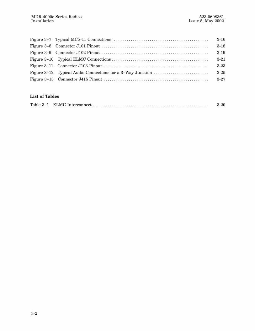
Figure 3-2�Digital Shelf I/O Connector Locations 3�6. . . . . . . . . . . . . . . . . . . . . . . . . . . . . . . . . . . . .
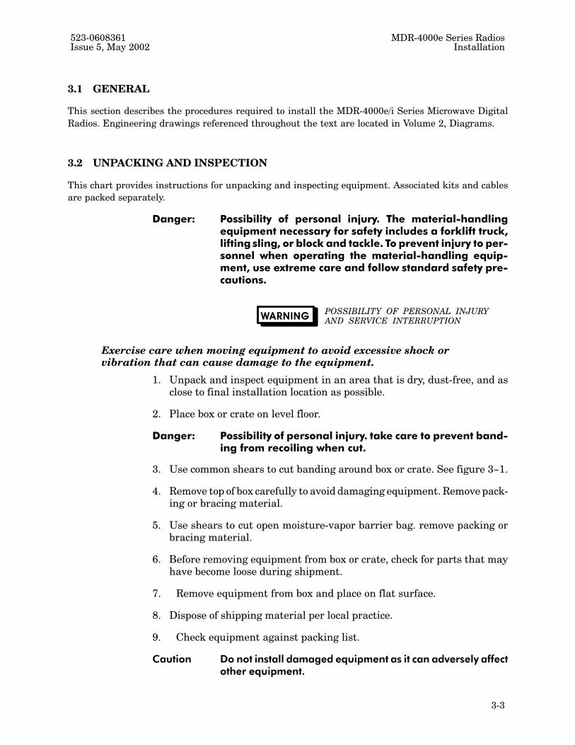
Figure 3-3�DS3 LBO/Interface Connections 3�9. . . . . . . . . . . . . . . . . . . . . . . . . . . . . . . . . . . . . . . . . .
Figure 3-4�DS1 I/O Connections 3�11. . . . . . . . . . . . . . . . . . . . . . . . . . . . . . . . . . . . . . . . . . . . . . . . . . . . .
Figure 3-5�DS1 Wirewrap Adapter Pinout 3�12. . . . . . . . . . . . . . . . . . . . . . . . . . . . . . . . . . . . . . . . . . . .
Figure 3-6�MCS�11 Rack Alarm Wiring 3�14. . . . . . . . . . . . . . . . . . . . . . . . . . . . . . . . . . . . . . . . . . . . . .
MDR�4000e Series Radios 523�0608361Installation Issue 5, May 2002
3�2
Figure 3-7�Typical MCS�11 Connections 3�16. . . . . . . . . . . . . . . . . . . . . . . . . . . . . . . . . . . . . . . . . . . . .
Figure 3-8�Connector J101 Pinout 3�18. . . . . . . . . . . . . . . . . . . . . . . . . . . . . . . . . . . . . . . . . . . . . . . . . . .
Figure 3-9�Connector J102 Pinout 3�19. . . . . . . . . . . . . . . . . . . . . . . . . . . . . . . . . . . . . . . . . . . . . . . . . . .
Figure 3-10�Typical ELMC Connections 3�21. . . . . . . . . . . . . . . . . . . . . . . . . . . . . . . . . . . . . . . . . . . . . .
Figure 3-11�Connector J103 Pinout 3�23. . . . . . . . . . . . . . . . . . . . . . . . . . . . . . . . . . . . . . . . . . . . . . . . . .
Figure 3-12�Typical Audio Connections for a 3-Way Junction 3�25. . . . . . . . . . . . . . . . . . . . . . . . . .
Figure 3-13�Connector J415 Pinout 3�27. . . . . . . . . . . . . . . . . . . . . . . . . . . . . . . . . . . . . . . . . . . . . . . . . .
List of Tables
Table 3-1�ELMC Interconnect 3�20. . . . . . . . . . . . . . . . . . . . . . . . . . . . . . . . . . . . . . . . . . . . . . . . . . . . . . .
523�0608361 MDR�4000e Series RadiosIssue 5, May 2002 Installation
3�3
3.1�GENERAL
This section describes the procedures required to install the MDR�4000e/i Series Microwave Digital
Radios. Engineering drawings referenced throughout the text are located in Volume 2, Diagrams.
3.2�UNPACKING AND INSPECTION
This chart provides instructions for unpacking and inspecting equipment. Associated kits and cables
are packed separately.
Danger: Possibility of personal injury. The material�handlingequipment necessary for safety includes a forklift truck,lifting sling, or block and tackle. To prevent injury to per�sonnel when operating the material�handling equip�ment, use extreme care and follow standard safety pre�cautions.
WARNINGPOSSIBILITY OF PERSONAL INJURYAND SERVICE INTERRUPTION
Exercise care when moving equipment to avoid excessive shock orvibration that can cause damage to the equipment.
1. Unpack and inspect equipment in an area that is dry, dust�free, and asclose to final installation location as possible.
2. Place box or crate on level floor.
Danger: Possibility of personal injury. take care to prevent band�ing from recoiling when cut.
3. Use common shears to cut banding around box or crate. See figure 3-1.
4. Remove top of box carefully to avoid damaging equipment. Remove pack�ing or bracing material.
5. Use shears to cut open moisture�vapor barrier bag. remove packing orbracing material.
6. Before removing equipment from box or crate, check for parts that mayhave become loose during shipment.
7. Remove equipment from box and place on flat surface.
8. Dispose of shipping material per local practice.
9. Check equipment against packing list.
Caution Do not install damaged equipment as it can adversely affectother equipment.

MDR�4000e Series Radios 523�0608361Installation Issue 5, May 2002
3�4
10. Inspect equipment for physical damage. If any items are missing ordamaged, immediately notify the transportation carrier and Alcatel.
11. Photograph all damaged equipment, and retain all inspection andpacking documentation for reference.
CARDBOARD
PACKED
LW403-0258-1
SHELF
BOX093092
CRADLE
VAPOR BAGMOISTURE-
Figure 3-1�Unpacking Diagram
3.3�RACK LOCATION
The rack�mounted equipment is designed for installation in a fixed equipment location. The specific lo�
cation of the rack is determined by the location of associated equipment and interconnection facilities.
The equipment room should be properly ventilated or air�conditioned to maintain the ambient tempera�
ture and humidity ranges specified in Section 1, General. Convection and conduction cooling maintain
proper temperatures in the rack.
3.4�RACK INSTALLATION
Refer to Appendix for step�by�step instructions.

523�0608361 MDR�4000e Series RadiosIssue 5, May 2002 Installation
3�5
3.5�MODULE INSTALLATION
Based on shipping requirements, modules may be shipped separately and may not be installed in
shelves. Expansion modules also may be received separately, after shipment of system.
POSSIBILITY OF EQUIPMENT DAMAGEAND SERVICE INTERRUPTION
CAUTION
Units with the electrostatic�sensitive (ESS) symbol contain ESS
devices. Store these units in an antistatic container when not in use,
and observe antistatic precautions when handling a unit. Damage to
unit may result if antistatic protection is not maintained. Refer to Spe�
cial Precautions pages in front of this manual for detailed handling in�
formation.
CAUTIONPOSSIBILITY OFSERVICE INTERRUPTION
Both A and B demodulators in the same rack must have the same part
number in order to have errorless switching.
All shelf modules are plug�in type. External connections to modules are by backplane connectors and
front�access cable connectors. To install modules, proceed as follows:
1. For module placement information, refer to Maintenance section.
2. Slide module into proper shelf guides (component side to left or up) until module contacts
shelf connector. Press firmly on handle(s) until card engages in shelf connector, and lock
handle(s) in card cage.
3. Connect front�access cable connectors as applicable.
3.6�BACKPLANE STRAPPING
The MDR�4000e backplane is strapped to default configurations at the factory. The strapping must be
checked against station/system requirements at installation. Refer to section 7 and check backplane
strapping as follows:
1. On RF backplane, strap A�side and B�side AGC normal (default).
2. On digital shelf backplane, connect ribbon cable between J1 and J2 for linear radio
application (default) or connect J2 to J3 for ring radio application.
3. On digital shelf backplane, strap A�side and B�side demodulator for lower or upper
sideband.
4. On digital shelf backplane, strap A�side and B�side modulator for APC enable.
3.7�EXTERNAL CONNECTIONS
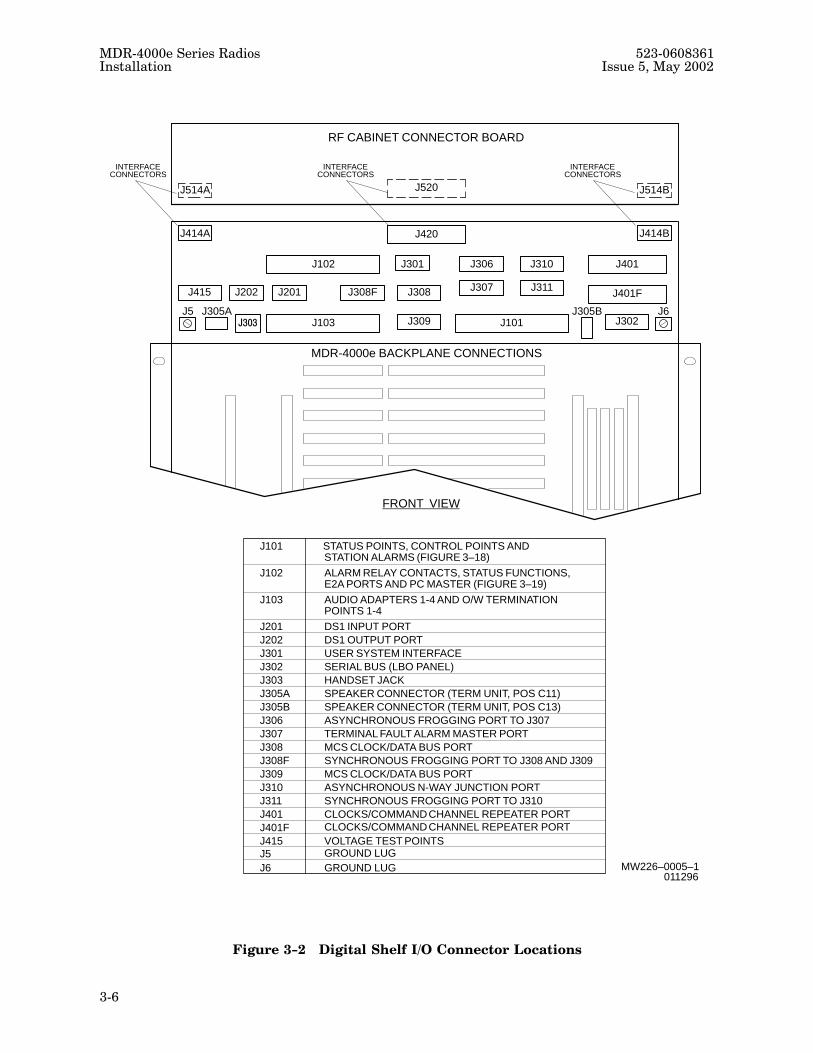
Figure 3-2 shows connector locations in the shelf. External connections to equipment consist of:
1. Transmission line interface.
MDR�4000e Series Radios 523�0608361Installation Issue 5, May 2002
3�6
RF CABINET CONNECTOR BOARD
J415 J202 J201 J308
J303
J102 J301 J306 J310 J401
J307 J311 J401F
J103 J309 J101
J414A J414B
J514A J514B
J420
J520
J5 J6J305A J305B
MDR-4000e BACKPLANE CONNECTIONS
J101 STATUS POINTS, CONTROL POINTS ANDSTATION ALARMS (FIGURE 3–18)
ALARM RELAY CONTACTS, STATUS FUNCTIONS,E2A PORTS AND PC MASTER (FIGURE 3–19)
AUDIO ADAPTERS 1-4 AND O/W TERMINATIONPOINTS 1-4
DS1 INPUT PORTDS1 OUTPUT PORTUSER SYSTEM INTERFACE SERIAL BUS (LBO PANEL)HANDSET JACKSPEAKER CONNECTOR (TERM UNIT, POS C11)SPEAKER CONNECTOR (TERM UNIT, POS C13)ASYNCHRONOUS FROGGING PORT TO J307TERMINAL FAULT ALARM MASTER PORTMCS CLOCK/DATA BUS PORTSYNCHRONOUS FROGGING PORT TO J308 AND J309MCS CLOCK/DATA BUS PORTASYNCHRONOUS N-WAY JUNCTION PORTSYNCHRONOUS FROGGING PORT TO J310CLOCKS/COMMAND CHANNEL REPEATER PORT
VOLTAGE TEST POINTS
J102
J103
J201J202J301J302J303J305AJ305BJ306J307J308J308FJ309J310J311J401J401FJ415
INTERFACECONNECTORS
INTERFACECONNECTORS
MW226–0005–1011296
FRONT VIEW
J302
J308F
CLOCKS/COMMAND CHANNEL REPEATER PORT
GROUND LUGJ5J6
GROUND LUG
INTERFACECONNECTORS
Figure 3-2�Digital Shelf I/O Connector Locations

523�0608361 MDR�4000e Series RadiosIssue 5, May 2002 Installation
3�7
2. Power and station ground connections, consisting of two negative and two positive
(A and B) battery circuit connections and a ground connection.
3. Input/output DS1 or DS3 data cable connections between radio rack and customer inter�
face equipment or between racks at repeaters.
4. Office alarms, monitor�control equipment, and orderwire connections.
3.8�Transmission Line Interface
Transmission line interface to an external antenna or antennas depends on the site equipment configu�
ration. Radios operating in the 2 GHz band have coaxial interfaces; all other bands have waveguide
interfaces. Refer to volume 2 for applicable interface points, installation kits, and hardware required for
each configuration.
3.9�Station Ground Connections
WARNING POSSIBILITY OFPERSONAL INJURY
To protect maintenance personnel from antenna tower lightning
strikes, the ground system must be integrated by bonding frame ground
and dc battery return together.
Station ground connections are different for standard racks and seismic racks. Refer to Appendix A,
chart 3, for more information.
3.10�Power Connections
The rack is internally wired to accept �24 or 48 V dc input power. The rack can operate from redun�
dant power sources or from a single power source. The dc battery connections are located at the top of
the rack assembly. Use the wire size chart shown in Appendix A, Chart 3 to determine the correct wire
gauge.
The negative battery is connected to negative (-) lug and the positive battery is connected to positive (+)
lug on the circuit card in the power distribution panel. If one source of battery is used, a jumper between
the lugs must be added.
Connect battery power as described in Appendix A, Chart 3.
3.11�DS3 I/O Connections/LBO Cards
External cable types for DS3 input/output should be AT&T�0 2734A or equivalent cable. Maximum
length is 450 ft to cross�connect. Alcatel equivalent cables are PN 425�0049�010, Teledyne VW�1 (black)
and PN 425�0049�020, Teledyne VW�1 (gray).
The DS3 interface/LBO cards are located at the top of the radio behind the power distribution unit front
cover (figure 3-3). Strap line buildout for appropriate distance to cross�connect. Refer to drawings in
MDR�4000e Series Radios 523�0608361Installation Issue 5, May 2002
3�8
section 7 for detailed instructions. The cards provide line buildout strapping for both A� and B�side
main, protect channel, or multiline, depending on whether the configuration is hot�standby, frequency
diversity, or 1:N. DS3 interface/LBO card applications/interconnections are as follows:
HOT�STANDBY/FREQUENCY DIVERSITY (PN 690�3703�001)
The LBO card has one pair of DS3 input/output connections and splits the signal to A� and B�side input/
output conditioners.
Connect: Line 1 input/output to MAIN LINE 1 IN/OUT connectors
Line 2 input/output to MAIN LINE 2 IN/OUT connectors
Line 3 input/output to MAIN LINE 3 IN/OUT connectors
PROTECT CHANNEL ACCESS (PN 690�3703�002)
The LBO card has two pairs of DS3 input/output connections. The first pair is for the priority traffic and
includes A� and B�side splitting/combining functions. The second pair is for the low�priority protection
channel access.
Connect: Line 1 input/output to MAIN LINE 1 IN/OUT connectors
Line 1 protect channel access to PROT CHAN ACCESS LINE 1 IN/OUT connectors
Line 2 input/output to MAIN LINE 2 IN/OUT connectors
Line 2 protect channel access to PROT CHAN ACCESS LINE 2 IN/OUT connectors
Line 3 input/output to MAIN LINE 3 IN/OUT connectors
Line 3 protect channel access to PROT CHAN ACCESS LINE 3 IN/OUT connectors
MULTILINE (1:N) (PN 690�3703�003)
The LBO card has two pairs of DS3 input/output connections to provide separate connections to input/
output conditioners for each RF channel.
Connect: Channel A line 1 input/output to A LINE 1 IN/OUT connectors
Channel B line 1 input/output to B LINE 1 IN/OUT connectors
Channel A line 2 input/output to A LINE 2 IN/OUT connectors
Channel B line 2 input/output to B LINE 2 IN/OUT connectors
Channel A line 3 input/output to A LINE 3 IN/OUT connectors
Channel B line 3 input/output to B LINE 3 IN/OUT connectors

523�0608361 MDR�4000e Series RadiosIssue 5, May 2002 Installation
3�9
MW126–0142–1010996
LBOLINE 1
LBOLINE 2
LBOLINE 3
POWER DISTRIBUTION PANELFRONT VIEW – PANEL REMOVED
TOP VIEW OF LBOs
POWER DISTRIBUTION PANELTOP VIEW
J1 J3
J2 J4
J1 J3
J2 J4
J1 J3
J2 J4
BATTERY INPUT
SERIAL INTFC CARD
FRONT VIEW
BACKPLANE(PCA ONLY)
A BATT– +
B BATT– +
(PCA ONLY)
Figure 3-3�DS3 LBO/Interface Connections

MDR�4000e Series Radios 523�0608361Installation Issue 5, May 2002
3�10
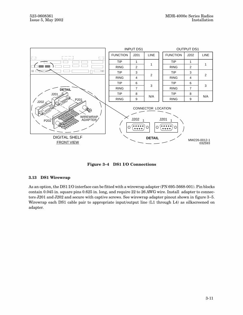
3.12�DS1 I/O Interface Cable Connections
See figure 3-4 for physical location of the I/O connectors. See electrical interconnect drawing in section
9 for detailed information. Three pairs of tip and ring (T&R) twisted, 22 AWG ABAM equivalent cable
should be used for input and three pairs for output connections. It is recommended that separate cables
be used for XMT and RCV. Maximum cable length is 650 feet. Set line buildout switches on DX�34N DS1
Interface for appropriate distance to cross�connect. Refer to drawings in section 7 for detailed instruc�
tions. A 50 ft cable kit with connectors (PN 695�4195�003) or connector kit only (PN 695�4195�004) is
available. For DS1 interface, connect data cables as follows:
POSSIBILITY OFCAUTION EQUIPMENT DAMAGE
Use wrist strap while installing cables.
1. On low�speed (1.544 Mb/s) cables, cut cable jackets and external shield as required to allow
twisted pairs of wires to be crimped to connector.
2. Place connector in crimp tool with pin 1 at bottom. Reverse color bar guide assembly. Re�
versing color bar guide assembly reverses tip and ring side of crimp tool from normal orien�
tation.
3. See section 9 for pin assignments and color codes. Pay close attention to T&R designations
for pins.
4. Crimp cable pairs onto connector. Remove connector from crimp tool. Assemble connector
and install hood.
5. Check continuity between cross�connect points and each low�speed connector pin.
6. Dress cables along rack channel. Use cable ties to secure cables to rack channels.
523�0608361 MDR�4000e Series RadiosIssue 5, May 2002 Installation
3�11
DIGITAL SHELFFRONT VIEW
1J202 1J201
FUNCTION
TIP
RING
TIP
RING
TIP
RING
TIP
RING
1
2
3
4
6
7
8
9
1
2
3
N/A
J201 LINE
INPUT DS1
FUNCTION
TIP
RING
TIP
RING
TIP
RING
TIP
RING
1
2
3
4
6
7
8
9
1
2
3
N/A
J202 LINE
OUTPUT DS1
MW226-0012-1032593
CONNECTOR LOCATION
J202
J201
P202
P201
WIREWRAPADAPTER
DETAIL
DETAIL
Figure 3-4�DS1 I/O Connections
3.13�DS1 Wirewrap
As an option, the DS1 I/O interface can be fitted with a wirewrap adapter (PN 695�5668�001). Pin blocks
contain 0.045 in. square pins 0.625 in. long, and require 22 to 26 AWG wire. Install adapter to connec�
tors J201 and J202 and secure with captive screws. See wirewrap adapter pinout shown in figure 3-5.
Wirewrap each DS1 cable pair to appropriate input/output line (L1 through L4) as silkscreened on
adapter.

MDR�4000e Series Radios 523�0608361Installation Issue 5, May 2002
3�12
MW226-0024-1032493
P102
P101
1 OUT
1 IN
L4 L3 L2 L1
L4 L3 L2 L1
P202 P201
Figure 3-5�DS1 Wirewrap Adapter Pinout
NOTE
Wirewrap adapters (Alcatel kit PN 695�4171�001) are available for
0.045 in. square pins 0.625 in. long, and require wire wrapping with 22
to 26 AWG wire.
3.14�MCS�11 Rack Alarm Connections
For correct station alarm polling communication, the rack alarms for MCS�11 polling requirements
should be wired to the first points on the station scanner for MCS detailed reporting. See figure 3-6.
NOTE
If PDU is wired negative ground, connect rack alarm as described in
step 1. If PDU is wired positive ground, connect rack alarm as described
in step 2.
1. Wire rack alarm visual (P102�50) to applicable station 1�16 alarm input on AE�35R Fault
Alarm Interface or station 17-32 alarm input on AE�78R Station Control Monitor via a
single wire between wirewrap adapters installed in J101 and J102 on digital shelf back�
plane. A typical connection scheme is given in the following example:
• Rack 1 (RSS address ON)
rack alarm visual (P102�50) in rack 1 to station 1 alarm input to AE�35R (P101-1)
in rack 1.
• Rack 2 (RSS address OFF)
rack alarm visual (P102�50) in rack 2 to station 2 alarm input to AE�35R (P101-2)
in rack 1.

523�0608361 MDR�4000e Series RadiosIssue 5, May 2002 Installation
3�13
• Rack 3 (RSS address OFF)
rack alarm visual (P102�50) in rack 3 to station 3 alarm input to AE�35R (P101-3)
in rack 1.
• Rack 32 (RSS address OFF)
rack alarm visual (P102�50) in rack 32 to station 32 alarm input to AE�35R
(P101-32) in rack 1.

MDR�4000e Series Radios 523�0608361Installation Issue 5, May 2002
3�14
MW126–0222–1091196
AE–37P/RCONTROLLER
1
P1
1
J1
POWERDISTRIBUTION UNIT
RACKALM
VISUALALARM
24
J520
24
J420
RFBACKPLANE
N.O.
N.C.
DIGITAL SHELF BACKPLANE
AE–78RSTATION
N.O.
N.C.
50
J102
A
POWERSUPPLY
B
BATTERY
RACKALARM17–32
AE–35RFA
CONTROL/MONITOR
J101
RACKALARM1–16
RACKALARM17–32
J308ALARMDATA
INTERFACE
WIRE–WRAPADAPTERS
WIRE–WRAPADAPTERS
SINGLE WIRE
RACK
3
J510
50
J102
VISUALALARMRACK
RACK ALARM VISUAL, RACK 2RACK 2
50RACK ALARM VISUAL, RACK 32
RACK 32
Figure 3-6�MCS�11 Rack Alarm Wiring

523�0608361 MDR�4000e Series RadiosIssue 5, May 2002 Installation
3�15
NOTE
MCS�11 systems allow 128 station addresses (RSS). The polling system
operates on a time level basis. The station alarms are polled first. If no
station alarms are present, the poll goes to the next address. If there is a
station alarm, the poll reverts to the lower level and scans the detail
alarms. For this to work, the rack alarm from each rack must be wired to
the rack with the station scanner turned on and addressed. All other
racks must have the RSS address turned off.
2. Wire rack alarm audio (P102�51) to applicable station 1-16 alarm input on AE�35R Fault
Alarm Interface or station 17�32 alarm input on AE�78R Station Control Monitor via a
single wire between wirewrap adapters installed in J101 and J102 on digital shelf back�
plane. Refer to the typical connection scheme given in step 1.
3. Properly dress wires and use cable ties to secure wires to rack channels.
3.15�MCS�11 Fault Alarm Connections
Refer to digital shelf application drawing (695�4161) and electrical interconnect drawing (695�417�643)
in volume 2 and connect MCS�11 fault alarm cables (695�4126�006 through �012) as shown for the appli�
cable system/rack configurations. If fault alarm polling system is Transmission Status Monitor
TSM�2500 or TSM�3500, enter MCS�11 mapping as listed in theory section tables 2�1, 2�2, and 2�3 and
shown in drawing 695�4170�638 in volume 2.
3.16�Typical MCS�11 Application
See figure 3-7 for a typical MCS�11 application diagram. In the scenario shown, the MDR�8000 series
radios makeup the backbone, with MDR�4000e and MDR�6000 series radios as junctions and spurs.

MDR�4000e Series Radios 523�0608361Installation Issue 5, May 2002
3�16
Figure 3-7�Typical MCS�11 Connections

523�0608361 MDR�4000e Series RadiosIssue 5, May 2002 Installation
3�17
3.17�TSM�2500/TSM�3500 Interface
If the fault alarm polling system is Transmission Status Monitor TSM�2500 or TSM�3500, enter MCS�11
mapping as listed in theory section tables 2�1, 2�2, and 2�3 and shown in drawing 695�4170�638 in
volume 2. Connect one port of polling engine to MCS�11 master and other port to connector J307 on
digital shelf.
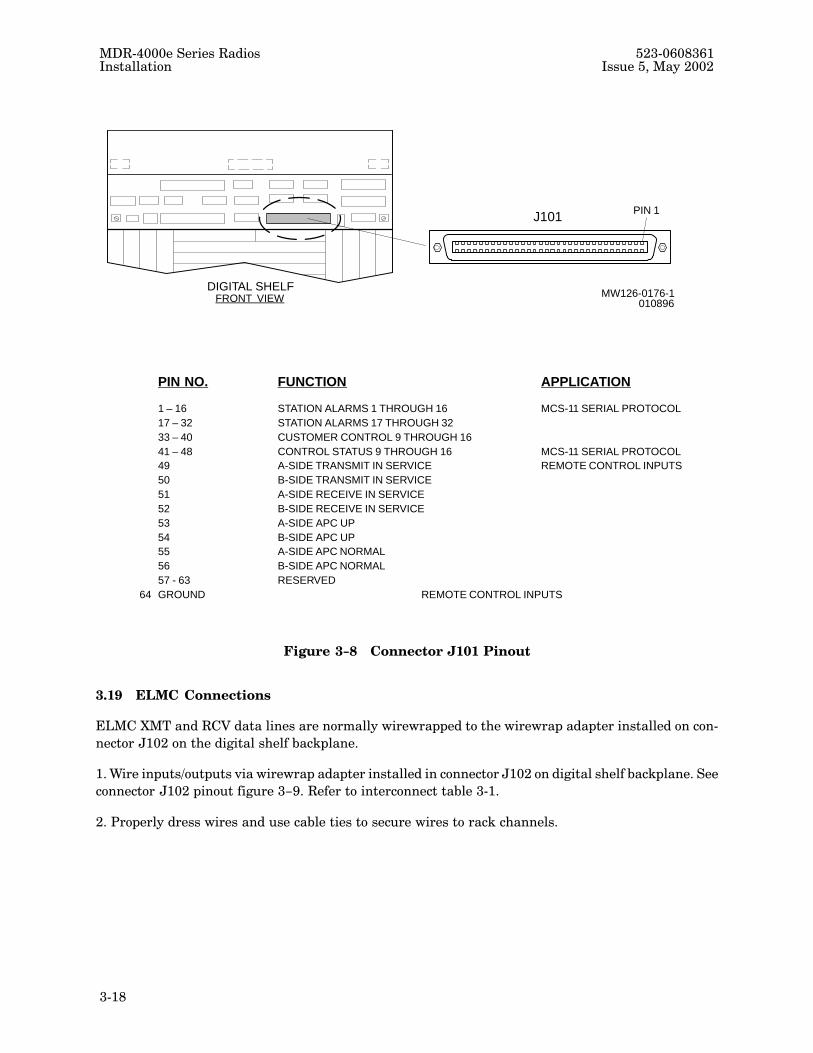
3.18�Controls and Relay Connections
Control inputs to the AE�27D Relay Interface module are normally wirewrapped to the wirewrap
adapter installed in connector J101 on the digital shelf backplane. Relay outputs from the AE�27D
Relay Interface module are normally wirewrapped to the wirewrap adapter installed in connector J102.
1. Wire applicable controls to inputs on AE�27D Relay Interface module via wirewrap adapt�
ers installed in connector J101 on digital shelf backplane. See connector J101 pinout
figure 3-8.
2. Wire applicable relay outputs of AE�27D Relay Interface module via wirewrap adapters
installed in connector J102 on digital shelf backplane. See connector J102 pinout
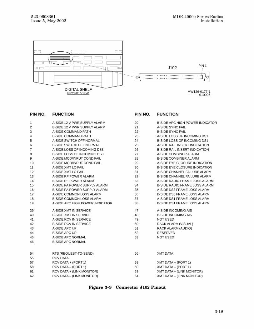
figure 3-9.
3. Provision relays normally open or normally closed depending on station requirements.
Refer to section 4.
4. Properly dress wires and use cable ties to secure wires to rack channels.
MDR�4000e Series Radios 523�0608361Installation Issue 5, May 2002
3�18
MW126-0176-1010896FRONT VIEW
DIGITAL SHELF
PIN 1J101
PIN NO. FUNCTION APPLICATION
1 – 16 STATION ALARMS 1 THROUGH 16 MCS-11 SERIAL PROTOCOL17 – 32 STATION ALARMS 17 THROUGH 3233 – 40 CUSTOMER CONTROL 9 THROUGH 1641 – 48 CONTROL STATUS 9 THROUGH 16 MCS-11 SERIAL PROTOCOL49 A-SIDE TRANSMIT IN SERVICE REMOTE CONTROL INPUTS50 B-SIDE TRANSMIT IN SERVICE51 A-SIDE RECEIVE IN SERVICE52 B-SIDE RECEIVE IN SERVICE53 A-SIDE APC UP54 B-SIDE APC UP55 A-SIDE APC NORMAL56 B-SIDE APC NORMAL57 - 63 RESERVED
64 GROUND REMOTE CONTROL INPUTS
Figure 3-8�Connector J101 Pinout
3.19�ELMC Connections
ELMC XMT and RCV data lines are normally wirewrapped to the wirewrap adapter installed on con�
nector J102 on the digital shelf backplane.
1. Wire inputs/outputs via wirewrap adapter installed in connector J102 on digital shelf backplane. See
connector J102 pinout figure 3-9. Refer to interconnect table 3�1.
2. Properly dress wires and use cable ties to secure wires to rack channels.
523�0608361 MDR�4000e Series RadiosIssue 5, May 2002 Installation
3�19
MW126-0177-1010996FRONT VIEW
DIGITAL SHELF
PIN 1J102
PIN NO. FUNCTION PIN NO. FUNCTION
1 A-SIDE 12 V PWR SUPPLY ALARM 20 B-SIDE APC HIGH POWER INDICATOR2 B-SIDE 12 V PWR SUPPLY ALARM 21 A-SIDE SYNC FAIL3 A-SIDE COMMAND PATH 22 B-SIDE SYNC FAIL4 B-SIDE COMMAND PATH 23 A-SIDE LOSS OF INCOMING DS15 A-SIDE SWITCH OFF NORMAL 24 B-SIDE LOSS OF INCOMING DS16 B-SIDE SWITCH OFF NORMAL 25 A-SIDE RAIL INSERT INDICATION7 A-SIDE LOSS OF INCOMING DS3 26 B-SIDE RAIL INSERT INDICATION8 B-SIDE LOSS OF INCOMING DS3 27 A-SIDE COMBINER ALARM9 A-SIDE MOD/INPUT COND FAIL 28 B-SIDE COMBINER ALARM10 B-SIDE MOD/INPUT COND FAIL 29 A-SIDE EYE CLOSURE INDICATION11 A-SIDE XMT LO FAIL 30 B-SIDE EYE CLOSURE INDICATION12 B-SIDE XMT LO FAIL 31 A-SIDE CHANNEL FAILURE ALARM13 A-SIDE RF POWER ALARM 32 B-SIDE CHANNEL FAILURE ALARM14 B-SIDE RF POWER ALARM 33 A-SIDE RADIO FRAME LOSS ALARM15 A-SIDE PA POWER SUPPLY ALARM 34 B-SIDE RADIO FRAME LOSS ALARM16 B-SIDE PA POWER SUPPLY ALARM 35 A-SIDE DS3 FRAME LOSS ALARM17 A-SIDE COMMON LOSS ALARM 36 B-SIDE DS3 FRAME LOSS ALARM18 B-SIDE COMMON LOSS ALARM 37 A-SIDE DS1 FRAME LOSS ALARM19 A-SIDE APC HIGH POWER INDICATOR 38 B-SIDE DS1 FRAME LOSS ALARM
39 A-SIDE XMT IN SERVICE 47 A-SIDE INCOMING AIS40 B-SIDE XMT IN SERVICE 48 B-SIDE INCOMING AIS41 A-SIDE RCV IN SERVICE 49 NOT USED42 B-SIDE RCV IN SERVICE 50 RACK ALARM (VISUAL)43 A-SIDE APC UP 51 RACK ALARM (AUDIO)44 B-SIDE APC UP 52 RESERVED45 A-SIDE APC NORMAL 53 NOT USED46 B-SIDE APC NORMAL
54 RTS (REQUEST-TO-SEND) 56 XMT DATA55 RCV DATA57 RCV DATA + (PORT 1) 59 XMT DATA + (PORT 1)58 RCV DATA – (PORT 1) 60 XMT DATA – (PORT 1)61 RCV DATA + (LINK MONITOR) 63 XMT DATA + (LINK MONITOR)62 RCV DATA – (LINK MONITOR) 64 XMT DATA – (LINK MONITOR)
Figure 3-9�Connector J102 Pinout

MDR�4000e Series Radios 523�0608361Installation Issue 5, May 2002
3�20
Table 3�1�ELMC Interconnect
MDR�4000E/IJ102CONNECTION
RDI�3100EJ9/J10CONNECTION
MDR�6000J309CONNECTION
MDR�8000J315/318CONNECTION
Pin 61 � RCV+ Pin 1 � Data Out + Pin 1 � Data Out + Pin 1 � LMC1 XMT +
Pin 62 � RCV- Pin 6 � Data Out - Pin 6 � Data Out - Pin 6 � LMC1 XMT -
Pin 63 � XMT+ Pin 2 � Data In + Pin 2 � Data In + Pin 2 � LMC1 RCV +
Pin 64 � XMT+ Pin 7 � Data In - Pin 7 � Data In - Pin 7 � LMC1 RCV -

523�0608361 MDR�4000e Series RadiosIssue 5, May 2002 Installation
3�21
Figure 3-10�Typical ELMC Connections

MDR�4000e Series Radios 523�0608361Installation Issue 5, May 2002
3�22
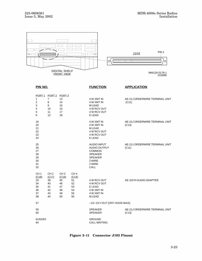
3.20�Service Channel Connections
Service channel inputs and outputs are normally wirewrapped to the wirewrap adapter installed in con�
nector J103 on the digital shelf backplane. See connector J103 pinout on figure 3�21.
NOTE
Position C17 (local channel #2) in the digital shelf must remain open
when the fault alarm interface is provisioned for MCS�11. Position C17
can be filled with AE�31H Audio Adapter when MCS�11 is not used.
1. Refer to section 7 and strap level and signaling options on the audio program card to match
station requirements.
2. Refer to section 7 and strap operating voltage and radio configuration (terminal, repeater,
or rail repeater) options on AE�31H Audio Adapter to match station requirements.
3. Refer to section 7 and strap programming options on AE�27X Data Adapter (if equipped)
to match station requirements. If AE�21J Audio Termination Unit C11 is equipped, per�
form step 4. If not go to step 5.
NOTE
The AE�21J Audio Termination Unit C11 has three ports for bridging
audio to up to three AE�31H Audio Adapter modules. Any port can be
connected to any audio adapter, however LOCAL OW PORT 1 is nor�
mally connected to AUDIO ADAPTER LOCAL CHAN 1, LOCAL OW
PORT 2 is normally connected to an audio adapter in channel 1 of a spur
route.
523�0608361 MDR�4000e Series RadiosIssue 5, May 2002 Installation
3�23
MW126-0178-1010996FRONT VIEW
DIGITAL SHELF
PIN 1J103
PIN NO. FUNCTION APPLICATION
PORT 1 PORT 2 PORT 31 7 13 4 W XMT IN AE-21J ORDERWIRE TERMINAL UNIT2 8 14 4 W XMT IN (C11)3 9 15 M LEAD4 10 16 4 W RCV OUT5 11 17 4 W RCV OUT6 12 18 E LEAD
19 4 W XMT IN AE-21J ORDERWIRE TERMINAL UNIT 20 4 W XMT IN (C13)21 M LEAD22 4 W RCV OUT23 4 W RCV OUT24 E LEAD
25 AUDIO INPUT AE-21J ORDERWIRE TERMINAL UNIT26 AUDIO OUTPUT (C11)27 COMMON28 SPEAKER29 SPEAKER30 2 WIRE31 2 WIRE32 CALL
CH 1 CH 2 CH 3 CH 4(C18) (C17) (C16) (C14)33 39 45 51 4 W RCV OUT AE-31F/H AUDIO ADAPTER34 40 46 52 4 W RCV OUT35 41 47 53 E LEAD36 42 48 54 4 W XMT IN37 43 49 55 4 W XMT IN38 44 50 56 M LEAD
57 –12/–19 V OUT (OFF-HOOK BIAS)
59 SPEAKER AE-21J ORDERWIRE TERMINAL UNIT60 SPEAKER (C13)
61/62/63 GROUND64 CALL WAITING
Figure 3-11�Connector J103 Pinout

MDR�4000e Series Radios 523�0608361Installation Issue 5, May 2002
3�24
4. See figure 3-12. Refer to MDR�4000e/i digital shelf audio kits drawing in volume 2 and
connect wires between pins on wirewrap adapter installed in connector J103 to meet audio
bridging requirements. The procedure for bridging audio at a typical 3�way repeater
follows:
(a) Wire AUDIO ADAPTER LOCAL CHAN (1) AUDIO OUT pins (2 each) to LOCAL
OW TERM PORT (1) AUDIO IN pins.
(b) Wire AUDIO ADAPTER LOCAL CHAN (1) AUDIO IN pins (2 each) to LOCAL OW
TERM PORT (1) AUDIO OUT pins.
(c) Wire AUDIO ADAPTER LOCAL CHAN (1) E�LEAD pin to LOCAL OW TERM
PORT (1) M LEAD pins.
(d) Wire AUDIO ADAPTER LOCAL CHAN (1) M�LEAD pin to LOCAL OW TERM
PORT (1) E LEAD pins.
Local O/W Terminal Port 2 Connects to Audio Adapter Local Chan 1 in Rack 3
(a) Wire AUDIO ADAPTER LOCAL CHAN (1) AUDIO OUT pins (2 each) to LOCAL
OW TERM PORT (2) AUDIO IN pins.
(b) Wire AUDIO ADAPTER LOCAL CHAN (1) AUDIO IN pins (2 each) to LOCAL OW
TERM PORT (2) AUDIO OUT pins.
(c) Wire AUDIO ADAPTER LOCAL CHAN (1) E�LEAD pin to LOCAL OW TERM
PORT (2) M LEAD pins.
(d) Wire AUDIO ADAPTER LOCAL CHAN (1) M�LEAD pin to LOCAL OW TERM
PORT (2) E LEAD pins.
5. Refer to MDR�4000e/i digital shelf audio kits drawing, orderwire interconnect drawing,
and service channel shelf drawing in volume 2 and connect wires to audio adapter input/
output pins on wirewrap adapter installed in connector J103 to meet audio requirements.
6. Properly dress wires and use cable ties to secure wires to rack channels.
NOTE
For channels 1 and P of multiline 1�N system, two 401 to 401F cables
(PN 7865�003/004) are required at repeaters to carry switch signals
end�to�end.

523�0608361 MDR�4000e Series RadiosIssue 5, May 2002 Installation
3�25
MW226–0100–1011697
24681012
1357911
343638
333537
E–LEADAUDIO OUTAUDIO OUTM–LEADAUDIO INAUDIO IN
E–LEADAUDIO OUTAUDIO OUTM–LEADAUDIO INAUDIO IN
AUDIO OUTAUDIO OUTE–LEADAUDIO INAUDIO INM–LEAD
LOCALO/W TERMPORT 2
LOCALO/W TERMPORT 1
AUDIOADAPTERLOCALCHAN 1
343638
333537
AUDIO OUTAUDIO OUTE–LEADAUDIO INAUDIO INM–LEAD
AUDIOADAPTERLOCALCHAN 1
WIREWRAP ADAPTERS
RACK 1 J103
RACK 3 J103
32
64
32
64
RACK 1
AUDIOADPTRNO. 1
O/WTERMUNIT
SCMLDM
RACK 3
TERMINAL
J401
401 CABLE
RACK 2
J401F
SCMLDM
REPEATER
J103
J103
6 4–WIRE AUDIO
AUDIOADPTRNO. 2
SCMLDM
SPUR
Figure 3-12�Typical Audio Connections for a 3�Way Junction

MDR�4000e Series Radios 523�0608361Installation Issue 5, May 2002
3�26
3.21�Service Channel Synchronous Repeater Connections
In this configuration, radio frame and overhead are phase�locked through repeaters end�to�end. The
service channel interconnect cable (401 cable) synchronizes the clocks of a back�to�back repeater using
connectors J401 and J401F on the digital shelf backplane. The 401 cable PN695�4194�XXX (for �001
shelf) or PN 695�7865�XXX (for �002, �004, and �006 shelves) is selected by length (12 to 50 ft).
1. Refer to section 7 and strap AE�31( ) Service Channel Muldem, installed in rack equipped
with AE�31( ) Audio Adapters, for service channel 1.
2. Strap AE�31( ) Service Channel Muldem installed in second rack for service channel 2.
3. Refer to MDR�4000i digital shelf application drawing in volume 2 and connect 401 cable
to connector J401 on the digital shelf backplane of rack equipped with AE�31( ) Audio
Adapters.
4. Connect 401 cable to connector J401F on the digital shelf backplane of second rack with
service channel muldem strapped for service channel 2.
5. Properly dress cables and use cable ties to secure cable to rack channel.
3.22�Orderwire Speakers
Refer to electrical interconnect drawing and cable drawings in volume 2 for installation support
information. Two physically different size speakers are provided as an option. Normally the larger
speaker has the better quality voice and is used for local orderwire. The smaller speaker is normally
used for express orderwire. Use the following procedure if the speaker option is required and not
already installed at the factory:
NOTE
The audio channel with termination kit PN 695�4173�002 and audio
channel with DTMF termination kit PN 695�4173�003 contain the
orderwire speaker (larger speaker) PN 271�0266�010 and connecting
cable
PN 694�0332�003.
1. Connect 2�wire cable assembly PN 694�0332�004 to connector J305A on digital shelf back�
plane.
2. Connect other end of cable to speaker in PDU.
3. Properly dress wires and use cable ties to secure wires to rack channels.
NOTE
Express terminal speaker kit PN 695�4173�004 contains the express
orderwire speaker (smaller speaker) and connecting cable.
4. If two speakers are used, connect second speaker using connector J305B on digital shelf
backplane.

523�0608361 MDR�4000e Series RadiosIssue 5, May 2002 Installation
3�27/(3�28 blank)
3.23�Test Connections
Test connector J415 pinout is shown in figure 3-13. This connector provides an interface for testing pur�
poses. An optional voltage monitor adapter (PN 695�5689�001) is also shown. This card provides isola�
tion and easy access to connector J415 while using a digital multimeter.
B-SIDE XMT LO VOLTAGE
B-SIDE DOWN-CONV AGC-2
DIGITAL SHELFFRONT VIEW
FUNCTION
A-SIDE DOWN-CONV AGC-1
A-SIDE DOWN-CONV AGC-2
A-SIDE IF AGC
A-SIDE RCV LO VOLTAGE
A-SIDE PA POWER MONITOR
A-SIDE XMT LO VOLTAGE
NOT USED
1
2
3
4
5
6
7-9
PIN/
MW126–0179–1010996
FUNCTION
B-SIDE DOWN-CONV AGC-1
B-SIDE IF AGC
B-SIDE RCV LO VOLTAGE
B-SIDE PA POWER MONITOR
10
11
12
13
14
15
PIN/
P415
J6 J5 J4 J3 J2 J1
J15 J14 J13 J12 J11 J10
OPTIONAL VOLTAGE MONITOR ADAPTER
JACK JACK
J415
PIN 1
VOLTAGE MONITOR ADAPTER
J415 1
CONNECTOR LOCATION
DETAIL
DETAIL
PN 695–5689–001
Figure 3-13�Connector J415 Pinout